

Page 1

Serial Converter
for use with
DPI AC Drives
M/N RECOMM-232
Instruction Manual
D2-3477
Page 2

The information in this manual is subject to change without notice.
Throughout this manual, the following notes are used to alert you to safety
considerations:
ATTENTION:Identifies information about practices or
circumstances that can lead to personal injury or death,
!
Important: Identifies information that is critical for successful application
!
property damage, or economic loss.
and understanding of the product.
ATTENTION:Only qualified ele ctrical p ers onn el familiar with
the construction and operation of this equipment and the
hazards inv olved should i nstall, adjust, operate, and/or service
this equipment. Read and understand this manual in its
entirety before proceeding. Failure to observe these
precautions could result bodily injury and/or damage to
equipment.
ATTENTION:If the serial conve rter is transmitting contro l I/O
to the product (indica ted by a solid gre en diamond LED), the
product may fault when you remove or reset the serial
converter. Determine how your product will respond before
removing or rese tting a connected se rial conv erter. F ailure to
observe this precaution could result bodily injury and/or
damage to equipment.
ATTENTION:The setting of Comm Flt Actio n (04) determines
the action of the serial con verter and connected product if DF1
serial communications are disrupted. By default, this
parameter faults the product. You can set this parameter so
that the product continues to run. Ensure that the setting of
this parameter does not create a hazard. Failure to observe
this precaution could result bodily injury and/or damage to
equipment.
ATTENTION:DPI host products must not be directly
connected together via RECBL cables. Unpredictable
behavior due to timing and other internal procedures can result
if two or more devices are connected in this manner. Failure
to observe this precaution could result bodily injury and/or
damage to equipment.
Reliance, SP600, DPI, and VS Utilities are trademarks of Rockwell
Automation.
Trademarks not belonging to Rockwell Automation are property of their
respective companies.
Copyright © 2001 Rockwell Automation. All rights reserved.
Page 3

CONTENTS
Chapter 1 About This Manual
1.1 Conventions Used in This Manual................................. 1-1
1.2 Features......................................................................... 1-1
1.3 Compatible Products..................................................... 1-1
1.4 Related Publications ......................................................1-2
1.5 Getting Assistance from Reliance Electric..................... 1-2
Chapter 2 Getting Started
2.1 Serial Converter Components....................................... 2-1
2.2 Required Equipment...................................................... 2-2
2.3 Installation Checklist ......................................................2-2
Chapter 3 Installing the Serial Converter
3.1 Selecting Cables............................................................ 3-1
3.2 Installing the Serial Converter................ ...... ..... ...... ...... .3-2
3.3 Removing the Serial Converter......................................3-2
Chapter 4 Configuring the Serial Converter
4.1 Configuration Tools........................................................ 4-1
4.2 Using the LCD OIM to Configure the Serial Converter.. 4-1
4.3 Using VS Utilities to Configure the Serial Converter......4-2
4.4 Using Terminal Emulation Software .............................. 4-3
4.4.1 Setting the Serial Port Rate.................................4-7
4.4.2 Setting the Fault Action ....................................... 4-8
4.4.3 Resetting the Serial Converter ............................ 4-9
Chapter 5 Troubleshooting the Serial Converter
5.1 Understanding the Status Indicators..............................5-1
5.1.1 Diamond Status Indicator....................................5-2
5.1.2 RX Status Indicator...................... ...... ..... ...... ....... 5-3
5.1.3 TX Status Indicator.............................................. 5-3
5.2 Module Diagnostic Items........................................ ...... .5-4
5.3 Viewing and Clearing the Event Queue......................... 5-4
5.3.1 Events.................................................................. 5-5
5.3.2 To Clear the Event Queue................................... 5-6
5.4 Viewing and Clearing DF1 Communication Statistics.... 5-6
5.4.1 To View DF1 Data............................................... 5-6
5.4.2 To Clear DF1 Data.............................................. 5-7
5.5 Troubleshooting Problems.............................................5-8
Contents
I
Page 4

Appendix A Technical Specifications..................................................... A-1
Appendix BSerial Converter Parameters...............................................B-1
Appendix CFlash Updates.....................................................................C-1
Glossary .................................................................................Glossary-1
Index ......................................................................................Index-1
II
Serial Converter for use with DPI AC Drives
Page 5

List of Figures
Figure 2.1 – Components of the Serial Converter......................................2-1
Figure 2.2 – Example of Serial Connection to a Computer.........................2-3
Figure 3.1 – Cables ....................................................................................3-1
Figure 3.2 – Connecting the Cables to the Serial Converter ...................... 3-2
Figure 4.1 – Configuring the Serial Converter Using the LCD OIM............ 4-1
Figure 4.2 – Using VS Utilities to Configure the Serial Converter...............4-2
Figure 4.3 – HyperTerminal Dialog Box in List View...................................4-3
Figure 4.4 – Connection Dialog Box........................................................... 4-4
Figure 4.5 – COM1 Properties Dialog Box..................................................4-5
Figure 4.6 – Converter Properties Dialog Box............................................ 4-6
Figure 4.7 – Hyperterminal Main Menu....................................................... 4-6
Figure 4.8 – Setting Comm Flt Action (04)..................................................4-8
Figure 4.9 – Resetting the Serial Converter................................................4-9
Figure 5.1 – Status Indicators on the Serial Converter............................... 5-1
Figure 5.2 – Viewing the Event Queue....................................................... 5-4
Figure 5.3 – Clearing the Event Queue...................................................... 5-6
Figure 5.4 – Viewing DF1 Data................................................................... 5-6
Figure 5.5 – Clearing DF1 Data..................................................................5-7
Contents
III
Page 6

IV
Serial Converter for use with DPI AC Drives
Page 7

List of Tables
Table 4.1 – Configuration Tools..................................................................4-1
Table 4.2 – Key Descriptions......................................................................4-7
Table 4.3 – Selections for Product Response to Communication Fault......4-8
Table 5.1 – Diamond Status Indicator: State Definitions ............................5-2
Table 5.2 – RX Status Indicator: State Definitions......................................5-3
Table 5.3 – TX Status Indicator: State Definitions......................................5-3
Table 5.4 – Diagnostic Items Accessed Using VS Utilities.........................5-4
Table 5.5 – Event Descriptions ..................................................................5-5
Table 5.6 – Troubleshooting the Serial Converter......................................5-8
Contents
V
Page 8

VI
Serial Converter for use with DPI AC Drives
Page 9

CHAPTER 1
About This Manual
This manual is intended for qualified electrical personnel.
1.1 Conventions Used in This Manual
The following conventions are used throughout this manual:
• Menu commands are shown in bold type face and follow the
format Menu > Comm and. F or e xample , if y ou read “Se lect F ile >
Open,” you should click the File menu and then click the Open
command.
• Parameters will be referenced as follows: DPI Port (01).
1.2 Features
Features of the serial converter include the following:
• Three status indicators (LEDs) report the operating status of the
adapter.
• Serial baud rates of 9600 bps, 19.2 Kbps, and 38.4 Kbps are
supported. 9600 bps is the factory def a ult .
• The serial converter can connect to products implementing DPI
such as SP600 drives. When used with a product, the serial
converter will autobaud to the DPI data rate that is used by the
product.
• The serial converter receives power from the connection to the
product. An outside power source is not needed.
• VS Utilities or terminal emulation software can be used to
configure the serial co n verter. In addi tio n, an LC D OI M (O pe ra tor
Interface Mod ule) ca n be u sed to confi gure a s erial co nverter that
is connected to an SP600 drive or other DPI product.
1.3 Compatible Products
The serial converter can be used with Reliance Electric products
that implement DPI, such as the SP600 AC drive.
About This Manual
1-1
Page 10

1.4 Related Publications
Refer to the following related publications as necessary for more
information:
• 1770-6.5.16 - DF1 Protocol a nd Co mmand Se t Reference Manual
• D2-3488 - VS Utilities Getting Results Manual
1.5 Getting Assistance from Reliance
Electric
If you have any questions or problems with the products described
in this instruction manual, contact y ou r loc al Re li anc e Ele ct ric sal es
office. For technical assistance, call 1-800-726-8112.
1-2
Serial Converter for use with DPI AC Drives
Page 11
CHAPTER 2
Getting Started
The serial converter provides an electronic communications
interface between a computer and any Reliance Electric product
implementing DPI. It uses the full-duplex, RS-232 DF-1 protocol.
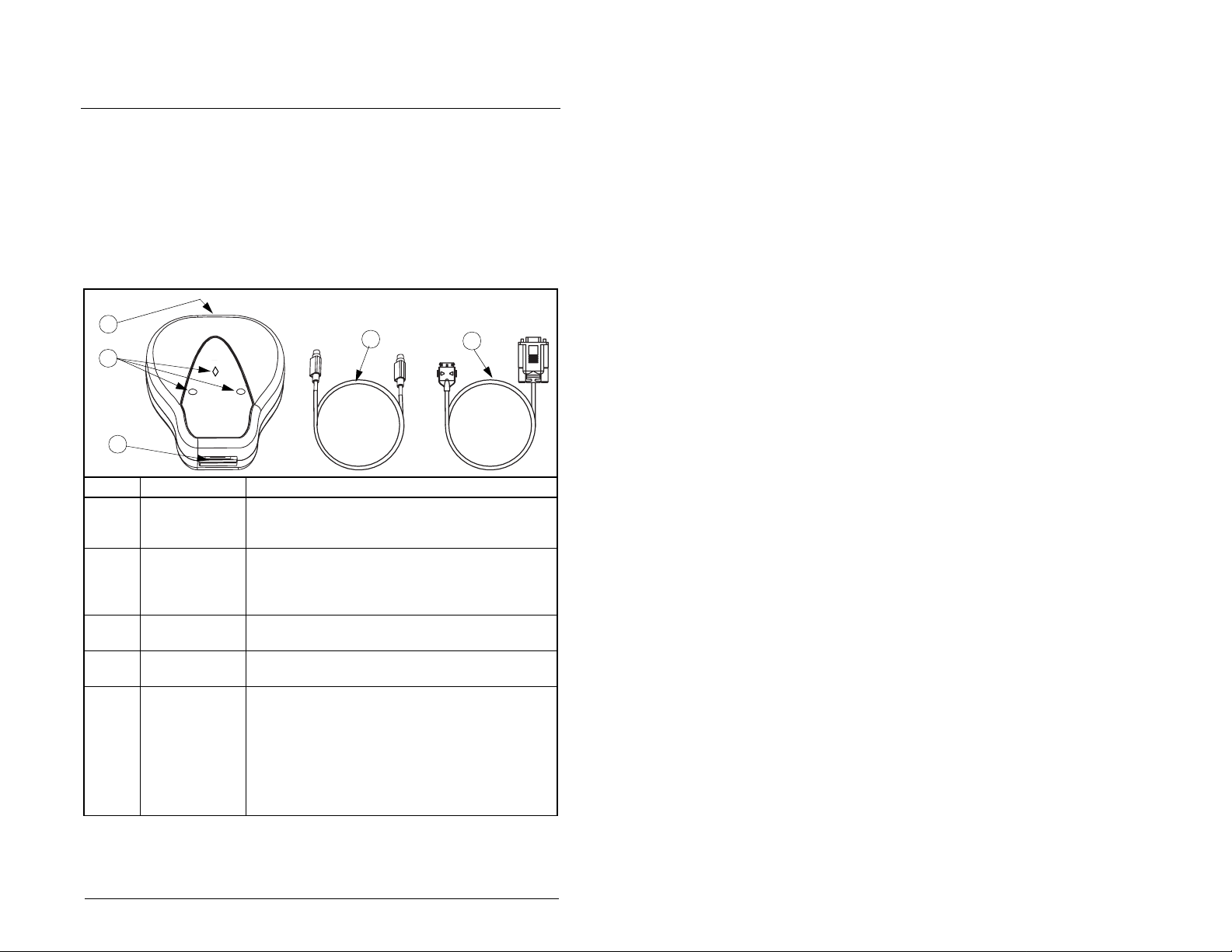
2.1 Serial Converter Components
1
2
3
# Part Description
1 DPI Connection Standard DPI 8-pin mini-DIN connector. The
2 Status
Indicators
3 RS-232 Serial
Port
4 RECBL-M10
Cable
5RECBL-SFC
Serial Cable
AB
RECBL-M10 cable (item 4) is plugged into this
connector.
LEDs that indicate module operation (data is
being received from the computer, data is being
sent to the computer). Refer to chapter 4,
Troub les ho oti ng, for more information.
Locking low-profile connector. The RECBL-SFC
serial cable (item 5) plugs into this connector.
DPI cable (1 m (3.3 ft)) with male-to-male
connectors.
Serial cable (2 m (6.6 ft)) with a locking low-profile
connector to connect to th e serial conv erter and a
9-pin sub-miniature female
D-connector to connect to a computer.
This cable can also be used to make a serial
connection to a ControlNet™ module or
DeviceNet™ module.
Figure 2.1 – Components of the Serial Converter
4
5
Getting Started
2-1
Page 12

2.2 Required Equipment
Equipment Shipped with the Serial Converter
When you unpack the serial converter, verify that the package
includes:
❑ One serial converter
❑ One RECBL-SFC serial cable
❑ One RECBL-M10 cable
User-Supplied Equipment
To configure the serial converter, you must use one of the following:
• VS Utilities software
• LCD Operator Interface Module (OIM)
• Terminal emulation software such as HyperTerminal
• VT-100 compatible terminal
2.3 Installation Checklist
This section is designed to help experienced users start using the
serial converter. If you are unsure how to complete a step, refer to
the referenced chapter.
2-2
Step Action Refer to
1 Review the safety precautions for the
serial converter.
2 Install the serial converter.
Connect a RECBL-M10 cable to the serial
converter and a compatible product. Then,
connect a RECBL-SFC serial cable to the
serial converter and a computer. Make sure
that power has been applied to the DPI
product.
3 Configure the serial converter parameters.
Use one of the following to configure
parameters in the serial converter:
• VS Utilites
Throughout
this manual.
Chapter 3,
Installing the
Serial
Converter
Chapter 4,
Configuring
the Serial
Converter
• OIM
• Terminal emulation software
• VT-100 compatible terminal
Serial Converter for use with DPI AC Drives
Page 13
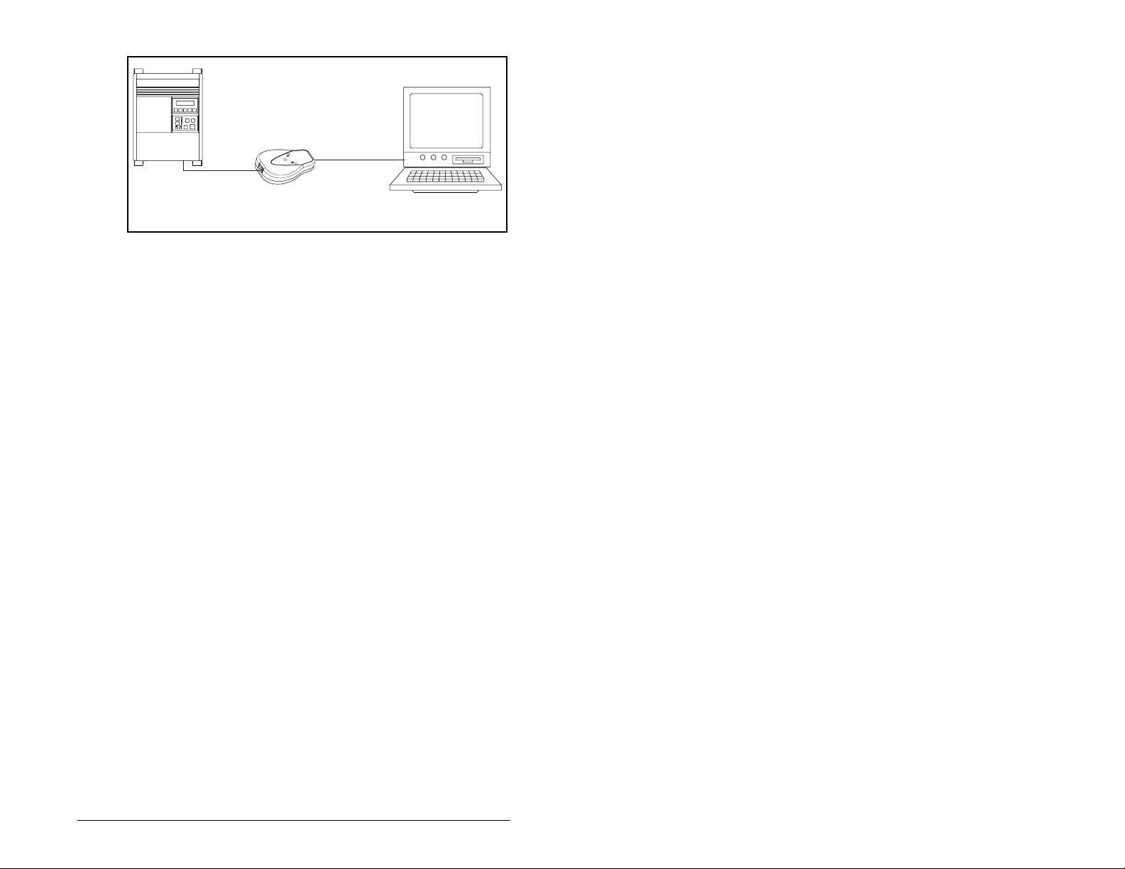
RECBL-M10
Cable
RECBL-SFC
Cable
Product
Serial
Converter
Figure 2.2 – Example of Serial Connection to a Computer
Computer
Getting Started
2-3
Page 14

2-4
Serial Converter for use with DPI AC Drives
Page 15
Installing the Serial Converter
Chapter 3 provides in structions f or installing and removing the serial
converter.
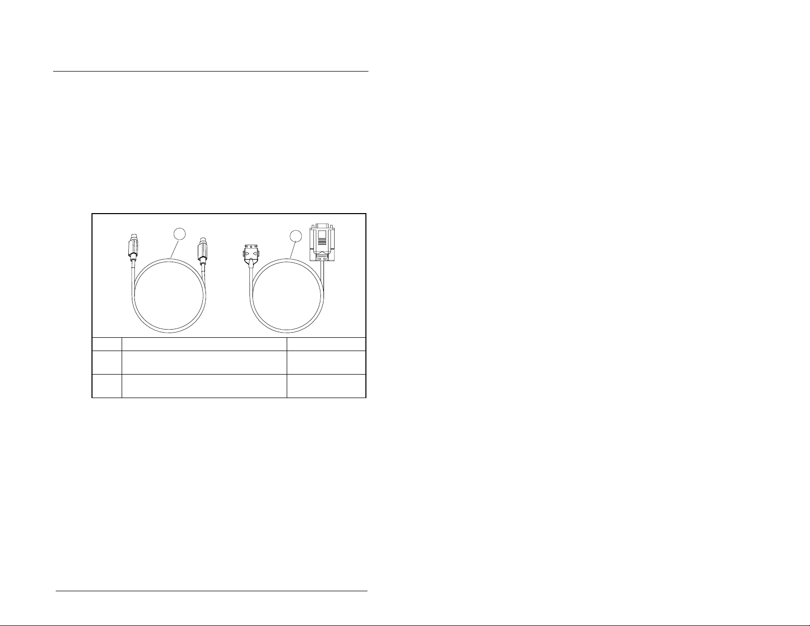
3.1 Selecting Cables
The following cables are all you should need to connect the serial
converter to a product and computer.
CHAPTER 3
1
# Description Part Number
1 DPI cable to connect the serial
converter to a drive.
2 Serial cable to connect the serial
converter to the computer.
Figure 3.1 – Cables
Important: To provide proper termination of the serial cable
shield, the computer chassis should be properly
grounded. If it is not poss ibl e or prac tical to g round th e
computer chassis, then a ground wire should be
connected to the serial cable shield at the shell of the
9-pin sub-miniature D-connector.
2
RECBL-M10
RECBL-SFC
Installing the Serial Converter
3-1
Page 16
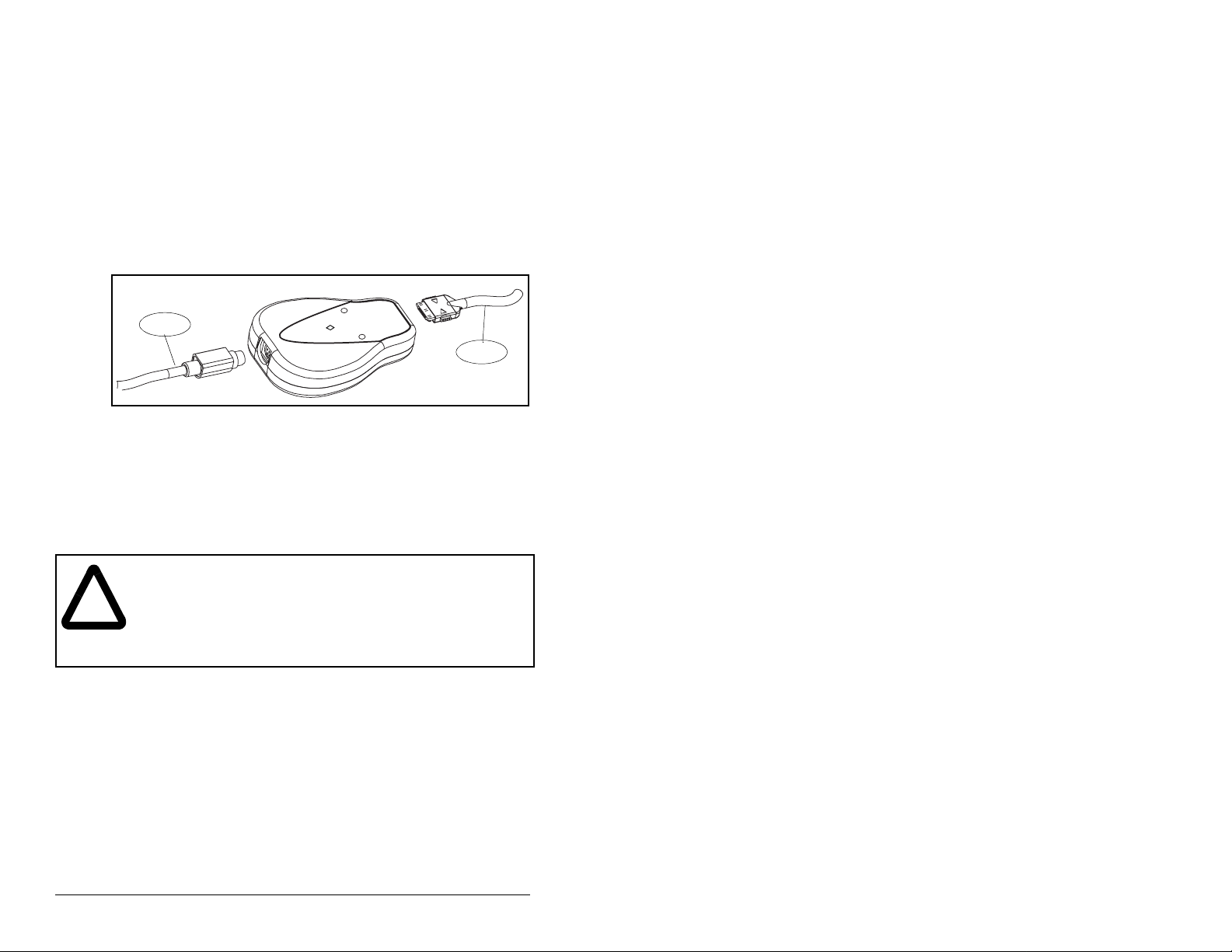
3.2 Installing the Serial Converter
Use the following procedure and refer to figure 3.2 to install the
serial converter.
Step 1. Connect the serial converter to the product using the
RECBL-M10 cable.
Step 2. Connect the converter to the computer using the
RECBL-SFC cable.
Step 3. Verify that power is applied to the product. The serial
converter receives power from the product. Therefore, the
product must be powered before the serial converter will
operate.
Step 1
Figure 3.2 – Connecting the Cables to the Serial Converter
The diamond light on the serial converter flashes green to indicate
that the serial converter is properly installed and receiving power. If
it is not green, refer to Chapter5, Troubleshooting.
TX
RX
3.3 Removing the Serial Converter
ATTENTION: If the serial co n v erter is transm itting c ontrol I/ O
to the product (indicated by a solid green diamond LED), the
product may fault when you remove or reset the serial
!
converter. Determine how your product will respond before
removing or rese tting a connected serial c onverter. Failure to
observe these precautions could result bodily injury and/or
damage to equipment.
Use The followoing procedure to disconnect the serial converter
Step 1. Disconnect the RECBL-M10 cable from the product and
then from the serial converter. To disconnect it, gently push
it in and then pull it out.
Step 2. Disconnect the RECBL-SFC serial cable from the serial
converter and then the computer.
Step 2
3-2
Serial Converter for use with DPI AC Drives
Page 17

Configuring the Serial Converter
This chapter provides information about configuring the serial
converter.
For a list of parameters, refer to Appendix B, Serial Converter
Parameters. For definitions of terms in this chapter, refer to the
Glossary.
4.1 Configuration Tools
The serial converter stores parameters and other information in its
own non-volatile storage (NVS). You must, therefore, access the
serial converter to view and edit its parameters. Table 4.1 lists tools
that you can use to access the serial converter and edit its
parameters.
Table 4.1 – Configuration Tools
Tool Refer to:
Operator Interface Module
(OIM)
VS Utilities software section 4.4 in this manual
Terminal emulation software section 4.5 in this manual
VT100-compatible terminal Documentation for the terminal
CHAPTER 4
sections 4.2 and 4.3 in this man u al
4.2 Using the LCD OIM to Configure the
Serial Converter
If you connect to a SP600 drive and it has an LCD OIM (Operator
Interface Module), you can use the OIM to access and edit
parameters in the serial converter as shown in figure 4.1. For
additional OIM information, refer to your SP600 AC Drive User
Manual.
Stopped
P0: SP600
Main Menu
Device Select
Monitor
Figure 4.1 – Configuring the Serial Converter Using the LCD OIM
Configuring the Serial Converter
Auto
Lang
Stopped
P0: SP600
Device: Port 0
SP600
RECOMM-232
Use to select
RECOMM-232.
Auto
Stopped
P0: RECOMM-232
Main Menu
Parameters
Edit the parameters
using the same
techniques as for drive
parameters.
Auto
4-1
Page 18

4.3 Using VS Utilities to Configure the Serial
Converter
With VS Utilities softw are , yo u can edit pa rameters in both the serial
converter and the connected product. On a DPI product (for
example, a SP600 drive), you can also edit parameters in any of the
attached peripherals.
This section is desig ned to hel p us ers start using VS Utiliti es. If you
are unsure how to complete a step, refer to the online help (select
Help > Help Topics).
Step 1. Select Explore > Configure Communication. Select the
Step 2. Select Explore > Connect > Local. A node appears
Step 3. In the left pane, click the + signs to expand the tree. Click
communications port and baud rate that you are using.
Select either checksum and accept the default time for the
time-out.
under Devices.
the product or se rial co n v erter to display parame ters in the
right pane. Double-click a parameter to edit it.
4-2
Figure 4.2 – Using VS Utilities to Configure the Serial Converter
Serial Converter for use with DPI AC Drives
Page 19

4.4 Using Terminal Emulation Software
This section provides detailed instructions on how to use terminal
emulation software to access the serial converter so that you can
view and edit serial converter parameters or view the serial
converter event queue.
A variety of terminal emulatio n prog ra ms can be use d to estab li sh a
serial connection betw een a compu ter and the serial con verter. The
following instructions describe how to establish the initial serial
connection to the serial converter using a computer running
HyperTer minal—terminal emulation software provided with most
Windows operating systems.
The following instructions use screen captures from Windows 95
HyperTerminal. If you are using Windows NT™, Windows 98,
Windows 2000, or Windows ME, HyperTerminal screens may differ.
To Use HyperTerminal to Access the Serial Converter
Step 1. Verify that the serial converter is installed correctly. Refer to
Step 2. On the Windows 95 desktop, click Start, and then select
chapter 3, Installing the Serial Converter.
Programs > Accesso ries > HyperT er minal to displa y the
HyperTerminal dialo g box (see figure 4.3). Your dialog bo x
may look slightly different. Continue to step 3.
On the Windows NT desktop, click Start, and then select
Programs > Accesso ries > HyperT er minal to displa y the
Connection dialog box (see figure 4.4). Then, go to step 6.
Figure 4.3 – HyperTerminal Dialog Box in List View
Step 3. Double-click Hypertrm.exe.
The Connection Description dialog box appears in the
HyperTerminal workspace.
Configuring the Serial Converter
4-3
Page 20

Figure 4.4 – Connection Dialog Box
Step 4. In the Name box, type any name (for example, converter),
and then select any icon in the Icon box.
Step 5. Click OK to display the Phone Number dialog box.
Step 6. In the Connect Using box, select the communications port
that you intend to use (usually COM1 or COM2).
Step 7. Click OK to display the Properties dialog box.
Step 8. Select the settings shown in figure 4.6.
Important: If you have previously set DF1 Rate Cfg (03) to 19.2K
or 38.4K, select that value in the Bits per second box.
4-4
Serial Converter for use with DPI AC Drives
Page 21

Figure 4.5 – COM1 Properties Dialog Box
Step 9. Click OK. A blank HyperTerminal workspace appears.
Step 10. Select File > Properties to display the P roperties dialog
box.
Step 11. Click Settings. See figure 4.7.
Step 12. Under the area labeled Function, arrow, and ctrl keys act
as, select Terminal keys.
Step 13. In the Emulation box, select VT100.
Configuring the Serial Converter
4-5
Page 22

Figure 4.6 – Converter Properties Dialog Box
Step 14. Click OK to display the HyperTerminal workspace.
Step 15. Select File > Save to save the HyperTerminal
configuration that you just created. In future connections,
you can sele ct the sav ed con figurati on and quic kly connect
to the serial converter.
Step 16. Press Enter until the main menu appears (see figure 4.8).
Main Menu - Enter Number for Selection
1> Display Setup Parameters
2> Display Event Queue
3> Flash Upgrade
Figure 4.7 – Hyperterminal Main Menu
To do this: See page(s):
Edit the serial port rate or fault action 4-7 through 4-10
View the event queue 5-3
View DF1 data 4- 6
Update the firmware C-1
4-6
Serial Converter for use with DPI AC Drives
Page 23

If no text or meaningless text appears instead of the Main Menu,
adjust the baud rate in your software. Refer to section 5.5 for
detailed instructions.
To Navigate in the Terminal Emulation Software
Table 4.2 describes the keys to used to navigate the terminal
emulation software.
Table 4.2 – Key Descriptions
Key Description
0
Esc
Enter
. . .
OR
OR
In the main menu, keys 1 – 3 select a menu option.
9
In the parameter screen, keys 0– 9 enter a value.
Display the main menu or abort changes to a
parameter.
Scroll through parameters or events.
Scroll through the values for a parameter.
Save a value for a parameter.
4.4.1 Setting t he Serial Port Rate
The serial port rate, sometimes called baud rate or DF1 rate, is the
speed at which the computer and serial converter communicate.
You can select a serial port rate of 9600, 19.2K, or 38.4K with the
serial converter. The factory default serial port rate is 9600.
Important: If you change the serial port rate in the serial converter,
To set the serial port rate
Step 1. Set DF1 Rate Cfg (03) to the desired rate.
Press the UP ARROW or DOWN ARROW key to scroll
through the parameter list. Press the LEFT ARROW or
RIGHT ARROW key to modify parameter values. Press
the ENTER key to save a new value.
you must set your software to use the same serial port
rate.
3> DF1 Rate Cfg = 9600
Step 2. Res et the serial co nverter. Refer to section 4.4.3.
Step 3. Set the serial port rate in your software to match the new
serial port rate in the serial converter.
Configuring the Serial Converter
4-7
Page 24

4.4.2 Setting the Faul t Action
ATTENTION: The setting of Comm Flt Action (04)
determines the action of the serial converter and
connected product if DF1 serial communications are
!
By default, when DF1 serial communications are disrupted (for
example, a seria l cable is disconnec ted) and control I/O is being
transmitted, the s erial co nverter and connected pro duc t res po nd by
faulting. You can set the actions listed in table 4.3.
:
Table 4.3 – Selections for Product Response to Communication Fault
Action Description
Fault The product will fault.
disrupted. By default, this parameter faults the
product. You can set this parameter so that the
product continues to run. Ensure that the se ttin g o f
this parameter does no t c r eat e a ha za rd. Failure to
observe this precaution could result bodily injury
and/or damage to equipment.
Stop The product will stop and not f ault (DPI ho st products
Zero
data
Hold last The product continues in its present state after a
To change the fault action, set the value of Comm Flt Action (04) to
the desired fault action. Refer to figure 4.8.
Press the UP ARROW or DOWN ARROW key to scroll
through the parameter list. Press the LEFT ARROW or
RIGHT ARROW key to modify parameter values. Press
the ENTER key to save a new value.
4> Comm Flt Action = Fault
Changes to this parameter take effect immediately. A reset is not
required.
only).
The product is sent 0 for output data after a
communication s disruption. This does no t c om m and
a stop.
communications disruption.
Figure 4.8 – Setting Comm Flt Action (04)
4-8
Serial Converter for use with DPI AC Drives
Page 25

4.4.3 Resetting the Serial Converter
ATTENTION: If the serial converter is transmitting
control I/O to the product (indicated by a so lid green
!
After you change some parameters, you must reset the serial
converter for the new setting to take effect. You can reset it by
removing and the n reappl ying po we r or b y usi ng Reset Module (0 5).
To reset the serial converter, set Reset Module (05) to either Reset
Module or Set Defaults. “Reset Module” will reset the serial
converter. “Set Defaults” will set all parameters in the serial
converter to their factory-default values. Refer to figure 4.9.
Press the UP ARROW or DOWN ARROW key to scroll
through the parameter list. Press the LEFT ARROW or
RIGHT ARROW key to modify parameter values. Press
the ENTER key to save a new value.
5> Reset Module = Reset Module
diamond LED), the product may fault when you
remove or reset th e serial converter . Determine how
your product will respond before removing or
resetting a connected serial converter. Failure to
observe this precaution could result bodily injury
and/or damage to equipment.
Figure 4.9 – Resetting the Serial Converter
After you enter the “Reset Module” value, the serial converter will be
reset. This parameter will then be reset to “Ready.”
Configuring the Serial Converter
4-9
Page 26

4-10
Serial Converter for use with DPI AC Drives
Page 27

CHAPTER 5
AB
Troubleshooting the Serial Converter
Chapter 5 provides information to troubleshoot the serial converter.
5.1 Understanding the Status Indicators
The serial converter reports its status using status indicators. See
figure 5.1.
1
2
3
Status
#
Indicator Descr iption Refer To
1 Diamond Serial converter status section 5.1.1
2 TX Serial converter is
transmitti ng data
3 RX Serial converter is
receiving data
Figure 5.1 – Status Indicators on the Serial Converter
section 5.1.2
section 5.1.3
Sections 5.1.1 through 5.1.3 describe what the state of each
indicator means. Note that if all status indicators are off, the serial
converter is not receiving power. Refer to chapter 3 for installation
instructions.
Troubleshooting the Serial Converter
5-1
Page 28

5.1.1 Diamond Status Indicator
ATTENTION: If the serial converter is transmitting control
I/O to the product (indic ated by a solid gr een diamond LED),
!
State Cause Corrective Action
Off S erial converter is
Flashing
Green
Solid
Green
Flashing
Red
Solid
Red
Orange Contact Reliance Electric Technical Support.
the product may fault when you remove or reset the serial
converter. Determine how your product will respond before
removing or resettin g a seri al con v erter . Failure to observe
this precaution could result bodily injury and/or damage to
equipment.
Table 5.1 – Diamond Status Indicator: State Definitions
not powered or in
Flash program ming
mode.
Serial converter is
operating and not
transmitting control
I/O.
Serial converter is
operating and is
transmitting control
I/O.
The product has
not acknowledged
the serial
converter.
Link Failure. • Securely connect cables.
• Securely connect cables.
• Apply power to the product.
• Wait while Flash is in progress.
No action. Removing or resetting the serial
conve rter will not cause a serial f au lt in the
product.
No action.
Securely connect cables.
• Replace the cable.
• Cycle power to the product.
5-2
Serial Converter for use with DPI AC Drives
Page 29

5.1.2 RX Status Indi ca tor
Table 5.2 – RX Status Indicator: State Definitions
State Cause Corrective Action
Off Serial con v erter is
not receiving data.
Flashing
Green
Serial converter is
receiving data
from the
computer.
• Verify that data is being transmitted.
• Securely co nne ct cables.
• Apply power to the product.
No action.
5.1.3 TX Status Indicator
Table 5.3 – TX Status Indicator: State Definitions
State Cause Corrective Action
Off Serial converter is
Flashing
Green
not transmitting
data.
Serial converter is
transmitting data
to the computer.
• Verify that data is being transmitted.
• Securely connect cables.
• Apply power to the product.
• Configure the computer software to use the
same serial port rate as the serial co nverter.
No action.
Troubleshooting the Serial Converter
5-3
Page 30

5.2 Module Diagnostic Items
The following diagnostic items can be accessed using VS Utilities.
Table 5.4 – Diagnostic Items Accessed Using VS Utilities
Name Description
Common Logic
Cmd
Prod Logic
Cmd
Reference Current value of the Product Spec ifi c Reference being
Common Logic
Sts
Prod Logic Sts Current value of the Product Specific Logic Status being
Feedbac k Current value of the Product Specifi c Feedback being
DPI Rx Err Current value of the DPI CAN Receive Error Counter
DPI Rx Err Max Maximum value of the DPI CAN Receive Error Counter
DPI Tx Err Current value of the DPI CAN Transmit Error Counter
DPI Tx Err Max Maximum value of the DPI CAN Transmit Error Counter
Field Flash Cntr Current value of the Field Flash Counter.
CPU CPU Type.
Current value of the Common Logic Command being
transmitted to the host by this peripheral.
Current value of the Product Specific Logic Command
being transmitted to the host by this peripheral.
transmitted to the host by this peripheral.
Current value of the Common Logic Status being received
from the host by this peripheral.
received from the host by this peripheral.
received from the host by this peripheral.
register.
register.
register.
register.
5.3 Viewing and Clearing the Event Queue
It is normal for the event queue in the serial converter to contain
events. If you encounter unexpected communication problems, you
can access the event queue and view the most recent events. To
view the event queue:
Step 1. Access the event queue using a configuration tool. Refer to
Step 2. Scroll through events in the event queue. The most recent
5-4
section 4.1.
event can be found at 2R > Event Queue 1 . See figure 5.2.
Press the UP ARROW or DOWN ARROW key to scroll
through the parameter list. Press the LEFT ARROW or
RIGHT ARROW key to modify parameter values. Press
the ENTER key to save a new value.
2R> Event Queue 1 = Pin ID Change
Figure 5.2 – Viewing the Event Queue
Serial Converter for use with DPI AC Drives
Page 31

5.3.1 Events
Many events in the Event queue occur under normal operation. If
you encounter unexpected communications problems, the events
may help you or Reliance Electric personnel troubleshoot the
problem. The following events may appear in the event queue:
Table 5.5 – Event Descriptions
Events Description
Bad Host Flt The serial converter was connected to an incompatible
Control Disabled The serial converter has sent a “Soft Control Disable”
Control Enabled The serial converter has sent a “Soft Control Enable”
DPI Bus Off Flt A bus-off condition was detected on DPI. This event may
DPI Fault Clear A DPI product has issued a fault clear message.
DPI Fault Msg The drive entered a faulted state.
Dup. Port Flt Another peripheral with the same port number is already
EEPROM Sum Flt The EEPROM in the serial converter is corrupt.
Host Sent Reset The DPI product issued this because it was reset.
Message Timeout The DPI product did not respond to a message request.
No Event Empty event queue entry.
Normal Startup Adapter initially powered up or was reset.
Online @
500kbps
PCCC I/O Time
Flt
Ping in Message An unexpected ping was received.
Ping Time Flt A ping message was not received on DPI within the
Port Change Flt The DPI port changed.
Port ID Flt The se rial conv erter is not connected to a c orrect port on
Type 0 Login The serial converter has logged in for type 0 control.
Type 0 Time Flt The serial converter has not received a type 0 status
Use I/O Sent The serial converter has begun sending product specific
product.
command to the DPI product.
command to the DPI product.
be caused by loose or broken cables or by noise.
in use.
Verify the cables are correct.
The serial conv erter and DPI product are commu nicating
at 500kbps.
The serial converter has not received a PCCC Control
message for longer than the specified PCCC Control
Time-out.
specified time.
a DPI product.
message within the specified time.
control information.
Troubleshooting the Serial Converter
5-5
Page 32

5.3.2 To Clear the Event Queue
Step 1. Access the event queue using a configuration tool. Refer
Step 2. Set the value of 1 > Clr Event Queue to Enable, and then
to section 4.1.
press Enter to clear the event queue. See figure 5.3.
Press the UP ARROW or DOWN ARROW key to scroll
through the parameter list. Press the LEFT ARROW or
RIGHT ARROW key to modify parameter values. Press
the ENTER key to save a new value.
1> Clr Event Queue = Enable
Figure 5.3 – Clearing the Event Queue
5.4 Viewing and Clearing DF1
Communication Statistics
If you encounter unexpected communications problems or are
creating an application that uses DF1 data, you can view the
communications statistics in the serial converter. Parameters 06
through 15 store this data.
In order to view and clear DF1 data, you must access the main
menu in the serial converter firmware. Refer to section 3.1.
5.4.1 To View DF1 Data
Step 1. Access the parameters in the serial converter using a
configuration tool. Refer to section 3.1.
Step 2. Scroll through the DF1 parameters. Parameters 06 through
15 contain DF1 data. See figure 5.4. For a description of
each parameter, refer to Appendix B, Serial Converter
Parameters.
Press the UP ARROW or DOWN ARROW key to scroll
through the parameter list. Press the LEFT ARROW or
RIGHT ARROW key to modify parameter values. Press
the ENTER key to save a new value.
7R> DF1 Packets Sent = 0
Figure 5.4 – Viewing DF1 Data
5-6
Serial Converter for use with DPI AC Drives
Page 33

5.4.2 To Clear DF1 Data
Step 1. Access the parameters in the serial converter using a
Step 2. Set the value of Clear DF1 Counts (06) to Clear Counts,
configuration tool. Refer to section 3.1.
and then press Enter to clear the DF1 data. See figure 5.5.
Press the UP ARROW or DOWN ARROW key to scroll
through the parameter list. Press the LEFT ARROW or
RIGHT ARROW key to modify parameter values. Press
the ENTER key to save a new value.
6> Clear DF1 Counts = Clear Counts
Figure 5.5 – Clearing DF1 Data
Troubleshooting the Serial Converter
5-7
Page 34

5.5 Troubleshooting Problems
Table 5.6 – Troubleshooting the Serial Converter
Problem Corrective Action
You are unable to
establish a connection
between your computer
and the serial converter.
After changing the serial
port rate, you are no
longer able to
communicate with the
serial converter and
connected product.
For example, in
HyperTer minal,
meaningless text
appears on the screen
when you pre ss Enter. In
VS Utilities, parameter
values are not updated.
You set a new serial port
rate, but the serial
converter is still using
the old serial port rate.
Y ou are using VS Utilities
and you cannot perform
any of the following:
• Route out over a
network, such as
DeviceNet to another
drive.
• Access DPI
peripherals such as
the RECOMM-DNET
DeviceNet adapte r.
• Access 32-bit data.
• If the status indicators are off, connect the
cables and apply power to the product.
• Configure y o ur soft ware a nd se rial con v erter to
use the same serial port rate (baud rate).
Reset the serial port rate in the software.
Instructions are included here for resetting the
serial port rate in HyperTerminal and VS Utilities.
If you are u sing a diff ere nt config uration tool, refer
to its user manual.
HyperTerminal
1.Select File > Properties, and then click
Configure.
2.Select the new baud rate, and then click OK.
3.Save and close HyperTerminal.
4.Double-click on your HyperTerminal file (*.ht) to
restart HyperTerminal.
5.Press Enter until the main menu appears.
VS Utilities
1.Select Explore > Configure Comm unicatio n.
2.Select the new baud rate. VS Utilities should
start updating values again. If it does not,
restart VS Utilities.
Reset the adapter. Refer to Chapter 4.
• Reserved (16) must be set to “Auto.”
• Reset the converter. See section 4.4.3.
5-8
Serial Converter for use with DPI AC Drives
Page 35

APPENDIX A
Technical Specifications
Communications
Network
Protocol
Port Rate
Data Bits
Parity
Stop Bits
Flow Control
Error
Product
Data Rate DPI: 500K
Electrical
Consumption 130mA at +12V DC
Mechanical
Dimensions 103.5 x 73.4 x 23.6 mm (4.08 x 2.89 x 0.93 in.)
RS-232 Serial DF1, Full Duplex
9600, 19.2K, or 38.4K
8
None
1
None
CRC or BCC (Auto-Detected)
The serial converter draws the required
power from the connected product. An
external power source is not required.
Weight 70.88 g (2.5 oz.)
Technical Specifications
A-1
Page 36

Environmental
Temperature
Operating
Storage
Relative Humidity 5 to 95% non-condensing
Vibration
Operating
Non-Operating
Shock
Operating
Non-Operating
0 to +50°C (32 to 122°F)
-40 to +85°C (-40 to 185°F)
2.5G @5Hz-2KHz
5 G @5Hz-2KHz
30 G peak acceleration, 11(+/-1)ms pulse
width
50 G peak acceleration, 11(+/-1)ms pulse
width
Regulatory Compliance
UL
CE
508C and CUL
EN-61800-3
A-2
Serial Converter for use with DPI AC Drives
Page 37

APPENDIX B
Serial Conv erter Parameters
This chapter presents inf ormation about the par ameters in the serial
converter.
01 DPI Port
Range: 0 t o 7
Default: 0
Type: Read Only
Port on the host product to which the serial converter is connected.
02 DF Addr Cfg
Range: 0 to 254
Default: 1
Type: Read/Write
Reset Required: Yes
DF1 node address for the serial converter. This is a decimal value.
03 DF Rate Config
Range: 0 = 9600
Default: 0
Type: Read/Write
Reset Required: Yes
Serial port rate for the DF1 serial port on the serial converter.
Serial Converter Parameters
1 = 19.2K
2 = 38.4K
B-1
Page 38

.
04 Comm Flt Action
Range: 0 = Fault
Default: 0
Type: Read Write
Reset Required: No
Action that the serial converter and product take if the serial
converter detects that DF1 serial communications are disrupted.
This setting is effective only if control I/O is transmitted through the
serial converter.
!
1 = Stop (DPI)
2 = Zero Data
3 = Hold Last
ATTENTION: Comm Flt Action (04) lets you
determine the action of the serial conver ter and
connected produc t if communications are disrupted.
By default, this parameter faults the pro duct. Y ou can
set this parameter so that the product continues to
run. Precautions should be take n to ensur e that the
setting of this parameter does not create a hazard
of injury or equipment damage. Failure to observe
this precaution could result in bodily injury.
05 Reset Module
Range: 0 = Ready
Default: 0
Type: Read/Write
1 = Reset Module
2 = Set Defaults
B-2
Ready No action.
Reset Module Resets the serial converter.
Set Defaults Restores the serial converter to its factory default
settings.
This parameter is a command. It will be set to “Ready” after a
“Reset Module” command or “Set Defaults” command has been
performed.
ATTENTION: If the serial converter is transmitting
control I/O to the product (indicated by a solid green
!
diamond LED), the product may fault when you
remove or rese t the serial converter . Determine how
your product will respond before removing or
resetting a connected serial converter. Failure to
observe this precaution could result in damage to,
or destruction of, the equipment.
Serial Converter for use with DPI AC Drives
Page 39

06 Clear DF1 Counts
Range: 0 = Ready
Default: 0
Type: Read/Write
No action if set to “Ready.” Resets the DF1 statistical parameters
(numbers 07 to15) to 0 if set to “Clear Counts.” This parameter is a
command. It will be reset to “0 = Ready” after a “Clear Counts”
command has been performed.
1 = Clear Counts
07 DF1 Packets Sent
Range: 0 to 4294967295
Default: 0
Type: Read Only
Number of DF1 packets sent by the serial converter. The value of
this parameter is normally approximately equal to the value of
DF1 Packets Rcvd (08).
08 DF1 Packets Rcvd
Range: 0 to 4294967295
Default: 0
Type: Read Only
Number of DF1 packets received by the serial converter. The value
of this parameter is normally approximately equal to the value of
DF1 Packets Sent (07).
09
Undelivered Msgs
Range: 0 to 65535
Default: 0
Type: Read Only
Number of DF1 messages that were sent but not acknowledged.
1
This value is normally a low v alue. If i t is continually incrementiong and you
are having communications problems, use a lower baud rate or replace
the RECBL-SFC serial cable.
Serial Converter Parameters
1
B-3
Page 40

10
ENQs Sent
Range: 0 to 65535
Default: 0
Type: Read Only
Number of ENQ characters sent by the serial converter.
1
11
ENQs Received
Range: 0 to 65535
Default: 0
Type: Read Only
Number of ENQ characters received by the serial converter.
12
NAKs Received
Range: 0 to 65535
Default: 0
Type: Read Only
Number of NAK characters received by the serial converter.
13
NAK Bad Packet
Range: 0 to 65535
Default: 0
Type: Read Only
Number of NAKs sent by the serial converter because of corrupt
packets (improper protocol messages) as determined by the serial
converter.
1
1
1
B-4
14
NAK No Memory
Range: 0 to 65535
Default: 0
Type: Read Only
Number of NAKs sent by the serial converter because it did not
have suffic ient memory to b uf f er the i ncom ing m essag es . The serial
conve rter runs out of m em ory if a co mm and has not completed and
there is no place to save the new commands.
1
This value is normally a low v alue. If i t is continually incrementiong and you
are having communications problems, use a lower baud rate or replace
the RECBL-SFC serial cable.
1
Serial Converter for use with DPI AC Drives
Page 41

15
Duplicate Msgs
1
Range: 0 to 65535
Default: 0
Type: Read Only
Number of duplicate messages sent by the serial converter. This
value contains the total number of consecutive messages received
by this device with the same TNS (Transaction Sequence) number.
16 (Reserved)
Range: 0 = Auto
Default: 0
Type: Read/Write
Auto: Converter will automatically run DPI if connected to a DPI
product.
17 DPI Data Rate
Range: 0 = 125 kbps
Default: 1
Type: Read Only
Data rate used by the DPI host product. This data rate is set in the
drive, and the adapter autobauds to it.
1 = 500 kbps
18 DFI Addr Actual
Range: 0 to 254
Default: 0
Type: Read Only
DF1 address actually used by the serial converter.
1
This value is normally a low value. If it is continually incrementiong and you
are having communications problems, use a lower baud rate or replace the
RECBL-SFC serial cable.
Serial Converter Parameters
B-5
Page 42

19
DFI Rate Actual
Range: 0 = 9600
Default: 0
Type: Read Only
Serial port rate actually used for the DF1 serial port on the serial
converter.
1 = 19.2 K
2 = 38.4K
20 Ref/Fdbk Size
Range: 0 = 16-bit
Default: 0
Type: Read Only
Size of the Reference/Feedback. The host product determines the
size of the Reference/Feedback. The serial converter automatically
uses the correct size.
1 = 32-bit
21 Datalink Size
Range: 0 = 16-bit
Default: 0
Type: Read Only
1 = 32-bit
B-6
Size of each Datali nk w ord. The h ost pro duct determines the s iz e of
Datalinks.
Serial Converter for use with DPI AC Drives
Page 43

APPENDIX C
Flash Updates
Appendix C provid es inf ormation on updati ng DPI hos t or peripheral
product firmware.
C.1 Preparing for a Flash Update
Please take the following precautions to ensure a successful flash
update:
• Obtain the n ew firmw are ver sion from Re liance Ele ctric. Sav e it to
the hard drive of the computer. Do not attempt to perform a flash
from a floppy disk or a network.
• Read all instructions supplied with the new firmware file.
• Use a computer running terminal emulation software that
supports Xmodem transfers (e.g., HyperTerminal).
• Record parameter values in the device that will be flashed.
Updates may reset parameters to their default settings.
• Ensure that the DPI host product (SP600 AC drive) is stopped.
• Close all programs except the terminal emulation program that
you are using to flash the serial converter.
• Disable the screen saver and antivirus programs so that they do
not start during th e flash process.
• If you are using a laptop computer, turn off the FIFO buffers in
HyperTer minal. In HyperTerminal, select File > Properties to
display the Properties dialog box. Click Configure, and then click
Advanced. Ensure that a check mark does not appear next to
Use FIFO buffers.
• Verify that Reserved (16) is set to “Auto” (default).
Flash Updates
C-1
Page 44

C.2 Performing a Flash Update with
HyperTerminal
ATTENTION:When you perf orm a flas h update , the
product will fau lt if it is receivi ng control I/O f rom the
!
Step 1. I n the main menu, press 3 to Update flash program.
If the serial converter is connected to a product implementing DPI, a
menu appears for you to select the device that you want to update.
See figure C.1
Flash Upgrade. Enter Number for Selection.
0 > SP600
1 > LCD OIM
2 > This RECOMM-232
5 > RECOMM-DNET
serial conv erter. V erify that the product h as stopped
safely or is receiving control I/O from an alternate
source before beginning a flash update. Failure to
observe this precaution could result bodily injury
and/or damage to equipment.
ATTENTION:If you interr upt a flash procedure that
is updating boot code, the device may become
inoperable. To prevent this damage, follow the
instructions prov ided with the ne w firmware file an d
do not interrupt a flash procedure while boot code is
being flashed. Failure to observe this precaution
could result bodily injury and/or damage to
equipment.
C-2
Figure C.1 – Flash Upgrade Menu
After you select a device by typing its number, a line appears to
confirm that you selected the right device and the following text
appears:
To update the flash memory, you need a terminal
program capable of downloading a binary file using
the XMODEM protocol and a flash update file from
Rockwell Automation. When you press ’Y’ to signal
that you are ready to proceed, the terminal program
will start displaying the letter ’C’. This signals
the XMODEM protocol that the download may proceed.
You then have one minute to start the transfer.
Press CTRL-X to cancel an update started by
mistake. Are you ready to proceed? (Y/N)
Serial Converter for use with DPI AC Drives
Page 45

Step 2. If the flash can be completed safely, type Y. The letter “C”
RECOMM232.bin
repeatedly appears . It is the Xmodem prompt an d continues
to appear until you send a binary file.
Important: Press Ctrl + X to cancel a flash update procedure.
Step 3. Select Transfer > Send File to display the send file dialog
box. See figur e C.2.
Step 4. Click Browse and navigate to the flash file.
Step 5. Double-click the file. Its name appears in the Filename box.
Step 6. In the Protocol box, select Xmodem.
Figure C.2 – Send File Dialog Box
Flash Updates
Step 7. Click Send. A dialog box appears and reports the progress
of the download. When it is complete, the message
“Operation Complete” appears.
Important: Keep the device powered for 15 seconds after the
operation has completed.
Step 8. Press Enter to return to the main menu.
C-3
Page 46

C.3 Troubleshooting Potential Flash
Problems
Table C.1 – Flash Troubleshooting
Problem Description Corrective Action
“Transfer Cancelled by
Remote System”
message appears and
the flash is not
completed.
The “Xmodem File Send”
for dialog box appears,
but the flash file is not
transferred.
After completing a flash,
you are unable to
communicate with the
serial converter. For
example, meaningless
text appears on the
HyperTer minal screen.
• Restart HyperTerminal and
repeat the flash procedure.
• If yo u are using Win dows N T 4.0,
install SP3 or later. Windows NT
service packs are available from
the Microsoft web site:
http://www.microsoft.com.
• Download a HyperTerminal
Private Edition update from the
Hilgraeve web site:
http://www.hilgraeve.com.
(Please note that there is a
license requirement with this
software.) Then, perform the
flash procedure again.
• Verify that you have selected the
Xmodem protocol i n the Sen d file
dialog box.
• Verify that the new file is on your
hard disk. Do not a ttempt to fl ash
from a floppy disk or a network.
• Verify that you are sending the
file within 60 second s of pressi ng
Y to confirm that you want to
perform the flash.
• Set the se rial port rate to 9600. If
parameters are c hanged during a
flash update, all parameters are
set to their default settings.
C-4
You are unable to initiate
a flash to a DPI host or
peripheral product.
• V e rify that Reserved (16) is set to
“Auto” (default set ting).
Serial Converter for use with DPI AC Drives
Page 47

GLOSSARY
application code - Code that runs in the adapter after the boot
code calls it. It performs the normal operations of the system.
block check character (BCC) - An error detection scheme where
the 2s complement of the 8-bit sum (modulo-256 arithm eti c su m) o f
all data bytes in a transmission block. It provides a means of
checking the accuracy of each message transmission.
boot code - Code that runs when the adapter fi rst recei ves pow er . It
checks basic operations and then calls the application code.
bus off - A bus off condi tion occurs when an ab normal rate of errors
is detected on the Contro l Area Ne tw ork (CAN) b us in a de vi ce . The
bus-off device cannot receive or transmit messages. This condition
is often caused by corruption of the network data signals due to
noise or data rate mismatch.
cyclic redundancy check (CRC) - An error detection scheme
where all of the characters in a message are treated as a string of
bits repres enting a binary number. This number is divided by a
predetermined binary number (a polynomial) and the remainder is
appended to the message as a CRC character. A similar operation
occurs at the receiving end to prove transmission integrity.
DF1 protocol - A peer-to-peer link layer protocol that combines
features of ANSI X3.28-1976 specification subcategories D1 (data
transparency) and F1 (two-way simultaneous transmission with
embedded responses ).
Glossary
DF1 rate - A unit of sig nal ing s pe ed eq ual to the number of di sc rete
conditions or signal events per second. It is also called “baud rate”
or “serial port rate.”
DPI - A peripheral communication interface used by various
Reliance Electric drives and power products.
DPI peripheral - A device that provides an interface between DPI
and a network or user. Peripheral devices are also referred to as
“adapters” and “module s.” The s erial conv erter and SP600 O IM are
examples of DPI peripherals.
DPI product - A de vic e that u ses the DP I comm unic ations i nter f ace
to communicate with one or more peripheral devices. For example,
a motor drive such as an SP600 AC drive is a DPI product. In this
manual, a DPI product is also referred to as “product” or “host.”
See
EEPROM -
non-volatile storage .
Glossary-1
Page 48

flash update - The process of updating firmware in a device.
hold last - When communicatio ns are disrupted (for example, a
serial cable is disconnected), the converter and product can
respond by holding last state. Hold last state results in the product
receiving the last data received via the DF1 connection before the
disruption. If the pro duc t was in R UN m ode an d u si ng the reference
from the converter, it will continue to run at the same reference.
non-volatile storage (NVS) - NVS is the permanent memory of a
device. Devices such as the converter store parameters and other
information in NVS so that they are not lost when the device loses
power. NVS is sometimes called “EEPROM.”
operator interface module (OIM) - A device that can be used to
configure and control an SP600 AC drive. An OIM can be used to
configure connected peripherals such as the serial converter.
programmable co ntroller communicati ons c omm and (PCCC) -
The protocol used b y some c ontrollers to commun icate wi th de vices
on a network. Some software products (for example, VS Utilities)
also use PCCC to communicate.
ping - A message that is sent by a DPI product to its peripheral
devices. They use the ping to gather data about the product,
including whether it can receive messages and whether they can
log in for control.
serial converter - A device that provides an electronic
communications interface between a DPI-based drive and a
computer with an RS-232 port. This converter uses a full-duplex
RS-232 DF1 protocol. The serial converter may also be referred to
as “converter” or “DPI peripheral.”
status indicators - LEDs that are used to report the status of a
device. There are three status indicators on the converter.
Type 0/Type 1/Type 2 Control - When tran smitting I/O , the adapter
can use diff eren t types of me ssag es f o r contro l. The Type 0, Type 1,
and Type 2 events help Relian ce Ele ctric pers onnel iden tify th e typ e
of messages that an adapter is using.
Xmodem - Developed by Ward Christensen in 1978, Xmodem is a
protocol used to tran sf er da ta. You can use the Xmodem prot ocol to
flash the firmware in the serial co nverter or a device conn ec ted to it.
zero data - When communications are disrupted (e.g., serial cable
is disconnected), the converter and product can respond with zero
data. Zer o data results in the product receiving zero as values for
command data. If the product was in RUN mode and using the
reference from the converter, it will stay in run mode but at zero
reference.
Glossary-2
Serial Converter for use with DPI AC Drives
Page 49

INDEX
A
adapter,
application code
see
serial converter
, Glossary-1
B
baud rate,
BCC
boot code
bus off
see
, A-1
, Glossary-1
, Glossary-1
DF1 rate
C
Checklist, installation, 2-2
, A-1
, A-1
, 5-6
, 5-6
see
serial converter
checksum
clearing DF1 data
clearing events
communications specifications
converter,
CRC
D
data bits, A-1
DF1
definition
viewing data
DF1 rate
definition
setting
dimensions
DPI
definition
peripheral
products
drives,
, Glossary-1
, Glossary-1
, 4-7
, A-1
, Glossary-1
, Glossary-1
see
DPI products
, 5-6
, Glossary-1
E
EEPROM,
see
non-volatile storage
(NVS)
, A-1
equipment
required
, 2-2
, 2-2
supplied
error detection
event queue
clearing events
list of events
viewing events
events
clearing
viewing
, A-1
, 5-4
, 5-4
F
fault action, 4-8
fault queue,
faults,
firmware, updating
flash update
flow control
see
see
definition
instructions
troubleshooting
event queue
events
, Glossary-2
, A-1
H
hold last
definition
setting
HyperTerminal
navigating in
updating firmware with
, Glossary-2
, 4-8
K
keys, 4-7
L
LCD OIM, 4-1
see
LEDs,
status indicators
M
, 5-6
, 5-5
, 5-4
, C-1
, C-1
, C-4
, 4-7
, C-4
Index
mechanical specifications, A-1
Index-1
Page 50

N
navigating in the firmware, 4-7
non-volatile storage (NVS)
definition
, Glossary-2
O
OIM (Operator Interface Module)
, 4-1
using
definition
, Glossary-2
event queue
resetting
serial port rate,
specifications
status indicators, definition
, A-1
stop bits
, 4-9
see
, A-1
, 5-4
DF1 rate
, Glossary-2
T
tools, <emphasis>see equipment
troubleshooting
, 5-1
P
parameters, list of, B-1 to ??
parity, A-1
, Glossary-2
PCCC
, Glossary-2
ping
power consumption
power cycle
products,
protocol
see
, A-1
, A-1
, 4-9
DPI products
R
regulatory compliance, A-2
resetting the converter
, 4-9
S
serial converter
definition
, Glossary-2
U
update,
see
flash update
V
viewing DF1 data, 5-6
X
Xmodem
definition
using to flash firmware
, Glossary-2
Z
zero data
definition
setting
, Glossary-2
, 4-8
, C-1
Index-2
Serial Convereter for use with DPI AC Drives
Page 51

Page 52

U.S. Drives Technical Support
Tel: (1) 262.512.8176, Fax: (1) 262.512.2222, Email: support@drives.ra.rockwell.com, Online: www.ab.com/support/abdrives
Publication D2-3477- July 2001 Copyright © 2001 Rockwell Automation, Inc. All Rights Reserved. Printed in USA.
 Loading...