

Page 1
Installation Instructions
RDD-Series Rotary Direct Drive Bearingless
Motors
Catalog Numbers RDB-B2901, RDB-B2902, RDB-B2903, RDB-B4101, RDB-B4102, RDB-B4103
Topic Page
Important User Information 2
Catalog Number Explanation 3
Before You Begin 4
Install the Motor 9
Remove the Motor 20
Connector Data 27
Product Dimensions 28
Connector Information 31
Specifications 31
Additional Resources 32
About the Direct Drive Bearingless Motors
RDD-Series direct drive motors feature single-turn or multi-turn high resolution
encoders. These bearingless housed motors provide a compact design for direct
drive applications.
Page 2
2 RDD-Series Rotary Direct Drive Bearingless Motor Installation Instructions
WARNING
IMPORTANT
ATTENTION
SHOCK HAZARD
BURN HAZARD
Important User Information
Solid state equipment has operational characteristics differing from those of electromechanical equipment.
Safety Guidelines for the Application, Installation and Maintenance of Solid State Controls, publication
, is available from your local Rockwell Automation sales office or online at
SGI-1.1
http://literature.rockwellautomation.com
equipment and hard-wired electromechanical devices. Because of this difference, and also because of the
wide variety of uses for solid state equipment, all persons responsible for applying this equipment must
satisfy themselves that each intended application of this equipment is acceptable.
In no event will Rockwell Automation, Inc. be responsible or liable for indirect or consequential damages
resulting from the use or application of this equipment.
The examples and diagrams in this manual are included solely for illustrative purposes. Because of the many
variables and requirements associated with any particular installation, Rockwell Automation, Inc. cannot
assume responsibility or liability for actual use based on the examples and diagrams.
No patent liability is assumed by Rockwell Automation, Inc. with respect to use of information, circuits,
equipment, or software described in this manual.
Reproduction of the contents of this manual, in whole or in part, without written permission of Rockwell
Automation, Inc., is prohibited.
Throughout this manual, when necessary, we use notes to make you aware of safety considerations.
Identifies information about practices or circumstances that can cause an explosion in
a hazardous environment, which may lead to personal injury or death, property
damage, or economic loss.
describes some important differences between solid state
Publication RDB-IN002B-EN-P — February 2010
Identifies information that is critical for successful application and understanding of
the product.
Identifies information about practices or circumstances that can lead to personal injury
or death, property damage, or economic loss. Attentions help you identify a hazard,
avoid a hazard and recognize the consequences.
Labels may be on or inside the equipment, for example, a drive or motor, to alert
people that dangerous voltage may be present.
Labels may be on or inside the equipment, for example, a drive or motor, to alert
people that surfaces may reach dangerous temperatures.
Page 3
RDD-Series Rotary Direct Drive Bearingless Motor Installation Instructions 3
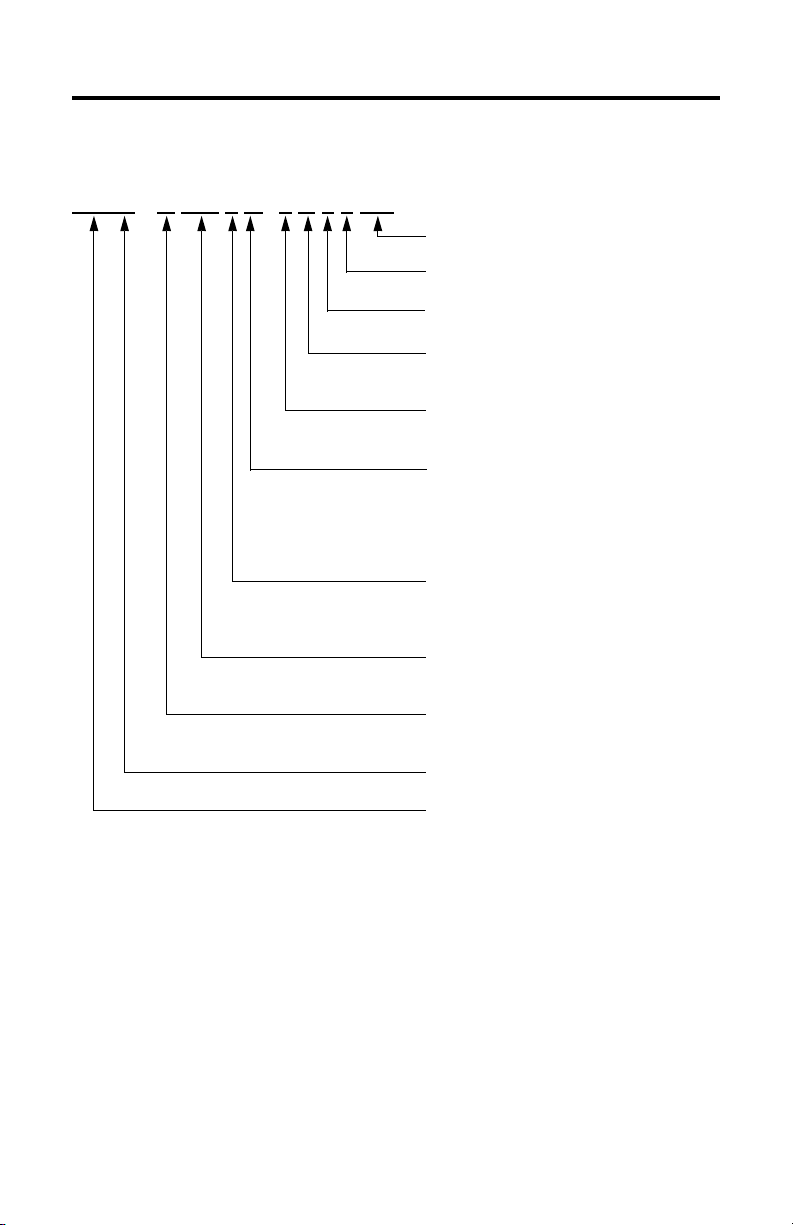
RD B -B 410 3 F -7B 7 2 AA
Catalog Number Explanation
FACTORY DESIGNATED OPTIONS
AA = Standard
BRAKE
2 = No Brake
CONNECTORS
7 = Circular, Right Angle, Feedback 180° Rotatable
ENCLOSURE/SHAFT
B = IP65 Housing/Blind Bore
T = IP64 Housing/Thru Bore
FEEDBACK
3 = Single-turn High Resolution Heidenhain
7 = Multi-turn High Resolution Heidenhain
BASE SPEED
4 = 200 rpm @ 440V
5 = 250 rpm @ 440V
6 = 375 rpm @ 440V
8 = 625 rpm @ 440V
9 = 750 rpm @ 440V
MAGNET STACKS
1 = One Stack
2 = Two Stacks
3 = Three Stacks
FRAME SIZE - Bolt Circle Diameter
290 = 290 mm
410 = 410 mm
VOLTAGE CLASS
A = 200V
B = 400V
HOUSING TYPE
B = Bearingless Housing
BULLETIN NUMBER
RD = Rotary Direct Drive Servo Motor
Publication RDB-IN002B-EN-P — February 2010
Page 4
4 RDD-Series Rotary Direct Drive Bearingless Motor Installation Instructions
ATTENTION
Before You Begin
Remove all packing material, wedges, and braces from within and around the item.
After unpacking, verify the nameplate catalog number against the purchase order.
1. Remove the motor carefully from its shipping container.
2. Visually inspect the motor frame, mounting pilot, and connectors for
damage.
3. Notify the carrier of any shipping damage immediately.
4. Retain the cardboard cover and protective paper sleeving from the mounting
end of the motor.
Magnetized material within the motor is exposed whenever the protective cover is
removed and before the motor is mounted.
Accidental entry of foreign material can harm motor performance.
Always cover the mounting end of motor immediately after removing the motor or its
protective cover. This will greatly reduce the possibility of magnetic or non-magnetic
particles accidentally entering the motor.
Publication RDB-IN002B-EN-P — February 2010
Page 5
RDD-Series Rotary Direct Drive Bearingless Motor Installation Instructions 5
Required Tools
These tools are needed to install this product.
Tools Required for Installation Value
Hex bit, 150 mm (6
Torque wrench Capable of applying at least 65 N•m (50 lb•ft)
Screwdriver Phillips #2
Micrometer N/A
Straight edge
Caliper
Runout indicator
Cleaning cloth
Shaft key (provided)
These additional tools are needed to remove this product.
Tools Required for Removal Value
M6 x 1 x 120 hex bolt or rod
(For RDB-B4103 motor only)
M10 and M12 hex bolts Qty 2 min
Flashlight N/A
Hammer
in.) minimum length 6 mm
Qty 1
Publication RDB-IN002B-EN-P — February 2010
Page 6

6 RDD-Series Rotary Direct Drive Bearingless Motor Installation Instructions
Prolonging Motor Life
Thoughtful design and proper maintenance can increase the life of this motor.
Follow these guidelines to maximize the life of the motor:
• Always provide a drip loop in each cable to carry liquids away from the
connection to the motor.
• If design requirements permit, provide shields that protect the motor
housing, shaft, seals, and their junctions from contamination by foreign
matter or fluids.
• Inspect the motor for damage or wear on a regular basis. If damage or
excessive wear is observed, replace the item.
Preventing Electrical Noise
ElectroMagnetic Interference (EMI), commonly called electrical noise, can reduce
motor performance. Effective techniques to counter EMI include filtering the AC
power, using shielded cables, separating signal cables from power wiring, and
practicing good grounding techniques.
Follow these guidelines to avoid the effects of EMI:
• Isolate the power transformers or install line filters on all AC input power
lines.
• Physically separate signal cables from motor cabling and power wiring.
Do not route signal cables with motor and power wires, or over the vent
openings of servo drives.
• Ground all equipment by using a single-point parallel ground system that
employs ground bus bars or large straps. If necessary, use additional
electrical noise reduction techniques to reduce EMI in noisy environments.
Refer to the System Design for Control of Electrical Noise Reference Manual,
publication GMC-RM001
Publication RDB-IN002B-EN-P — February 2010
, for additional information on reducing the effects of EMI.
Page 7
RDD-Series Rotary Direct Drive Bearingless Motor Installation Instructions 7
Build and Route Cables
Knowledgeable cable routing and careful cable construction improves system
performance.
Follow these guidelines to build and install cables:
• Keep wire lengths as short as physically possible.
• Route noise sensitive wiring (encoder, serial, I/O) away from input power
and motor power wiring.
• Separate cables by 0.3 m (1 ft) minimum for every 9 m (30 ft) of parallel
run.
• Ground both ends of the encoder cable shield and twist the signal wire
pairs to cancel electromagnetic interference (EMI) from other equipment.
WARNING
Do not tightly gather or coil the excess length of a power cable. Heat is generated within
a cable whenever power is applied. Always position a power cable so it may freely
dissipate any heat.
A power cable should not be coiled b
Design for Control of Electrical Noise Reference Manual, publication GMC-RM001
information on how to handle excess cable lengths.
Failure to observe these safety procedures could result in personal injury or equipment
damage.
y itself or with other power cables. Refer to System
, for
Publication RDB-IN002B-EN-P — February 2010
Page 8
8 RDD-Series Rotary Direct Drive Bearingless Motor Installation Instructions
SHOCK HAZARD
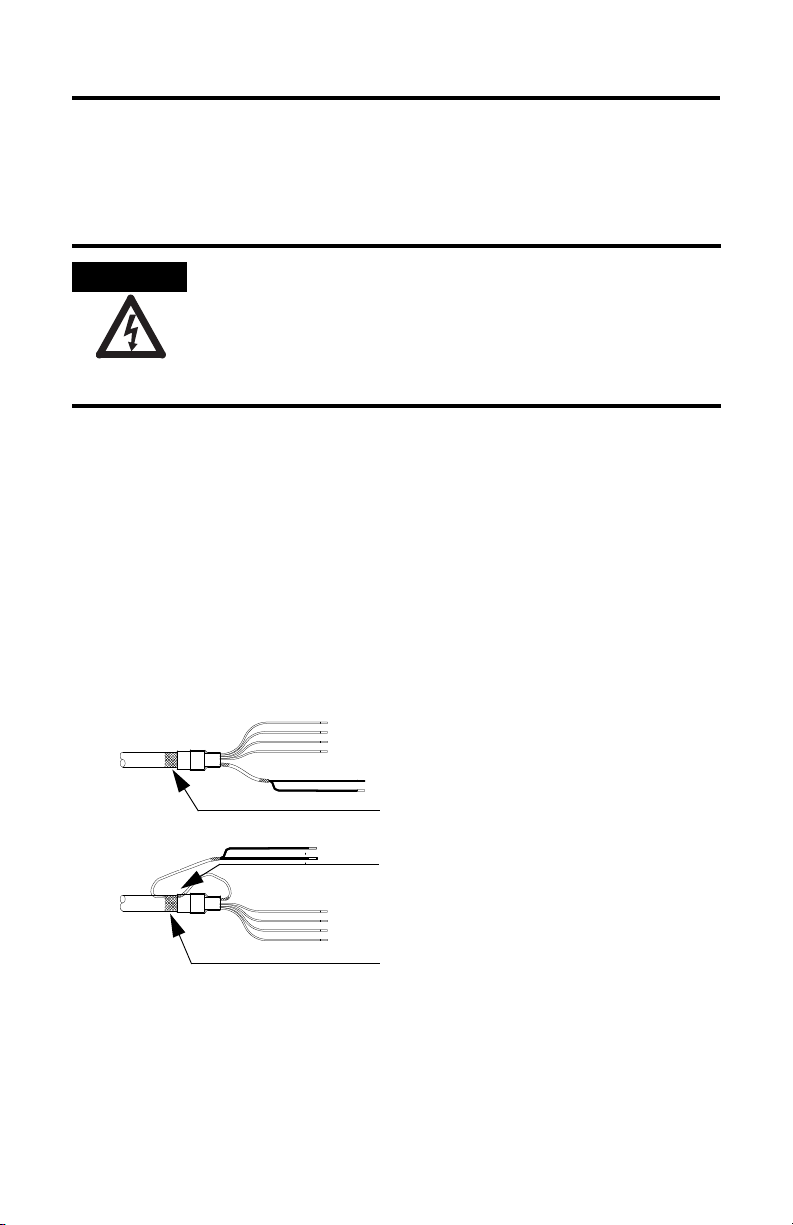
Shielded Signal Wires (one pair shown) within Power
Cable
Overall Power Cable Shield
Signal Wire Shield Contacts Overall Power
Cable Shield
Factory Supplied
Field Modified
All power and signal wire shields must connect to
machine ground.
Ground the Shielded Signal Wires within a Power Cable
Always ground the shield on any signal wires inside a power cable. Connecting this
shield to chassis ground reduces the potential for voltage inductance and EMI.
If any shield on a power cable is not grounded, high voltage can be present on that
shield.
Make sure there is a connection to ground for all shield wires inside a power cable, and
for the overall power cable shield.
Failure to observe safety precautions could result in personal injury or damage to
equipment.
To ground the shield wire on a 2090-CPBM7DF-xxAFxx or 2090-XXNPMF-xxSxx
power cable:
1. Loop the signal wire pair to the overall cable shield as shown in the
diagram.
• Cable 2090-CPBM7DF-xxAFxx (shown) contains one signal wire pair.
• Cable 2090-XXNPMF-xxSxx contains two signal wire pairs.
2. Clamp all signal wire shields and the overall power-cable shield in the
power cable (chassis) ground clamp on the drive.
Grounding of Signal Wire Shields in a Power Cable
Publication RDB-IN002B-EN-P — February 2010
Page 9
RDD-Series Rotary Direct Drive Bearingless Motor Installation Instructions 9
ATTENTION
ATTENTION
ATTENTION
Install the Motor
All motors include a mounting pilot for aligning the motor on the machine.
Preferred fasteners are hardened steel. The installation must comply with all local
regulations and use equipment and installation practices that promote safety and
electromagnetic compatibility.
Unmounted motors, disconnected mechanical couplings, loose shaft keys, and
disconnected cables are dangerous if power is applied.
Disassembled equipment should be appropriately identified (tagged-out) and access to
electrical power restricted (locked-out).
Before applying power to the motor, remove the shaft key and other mechanical couplings
that could be thrown from the shaft.
Failure to observe these safety precautions could result in personal injury.
Servo drive power must be turned off before connecting or disconnecting the cables to the
motor, and if a cable is left disconnected at the motor end.
Arcing or unexpected motion could occur if the feedback, power, or brake cables are
connected or disconnected while power is applied to the servo drive.
Failure to observe these safety procedures could result in personal injury or damage to the
motor and equipment.
Only an authorized Allen-Bradley repair center shall service this item. Refer to Rockwell
Automation Support for assistance to locate the nearest repair center.
Failure to observe safety precautions could result in personal injury or damage to
equipment.
Publication RDB-IN002B-EN-P — February 2010
Page 10
10 RDD-Series Rotary Direct Drive Bearingless Motor Installation Instructions
BURN HAZARD
Preparing the Motor for Installation
Follow these steps to prepare a motor for installation.
1. Verify sufficient clearance, heatsink mass, and air flow for the motor so it
stays within the operating temperature range of 0…40 °C (32…104 °F).
Do not enclose the motor unless cooling air is forced across the motor, and
keep other heat producing devices away from the motor. Heatsink
requirements are listed in a footnote to the Specifications
Outer surfaces of a motor can reach high temperatures, 125 °C (275 °F), during operation.
Take precautions to prevent accidental contact with hot surfaces. Consider motor surface
temperature when selecting connections and cables to install on a motor.
Failure to observe safety precautions could result in personal injury or damage to
equipment.
2. Wipe the shaft and the rotor hub to remove excess grease or other
contaminants.
A light oil coating is acceptable.
table.
Publication RDB-IN002B-EN-P — February 2010
Page 11

RDD-Series Rotary Direct Drive Bearingless Motor Installation Instructions 11
Machine
Mounting
Surface
Small Shaft
Diameter
Large Shaft
Diameter
Pilot
Diameter
Small Shaft Length
Overall Shaft Length
Pilot
Extension
Verify Machine Mounting Dimensions
Verify proper fit of the motor to the machine mount by measuring the following
machine mounting dimensions:
1. Verify these dimensions are within the measurement range in the tables:
• Pilot diameter
• Shaft diameter, large and small
• Shaft length, small and overall
2. Verify the Total Indicator Readout (TIR) of these dimensions is less than the
value in the tables when measured with a dial indicator:
• Shaft runout
• Pilot concentricity
• Mounting surface perpendicularity
Machine Mounting Dimensions
Publication RDB-IN002B-EN-P — February 2010
Page 12

12 RDD-Series Rotary Direct Drive Bearingless Motor Installation Instructions
RDB-B2901, RDB-B2902, RDB-B2903 Machine Mounting Dimensions
Attribute Value
Pilot diameter 232.92…232.96 mm (9.170…9.172 in.)
Shaft diameter, small 59.988…59.999 mm (2.3617…2.3622 in.)
Shaft diameter, large 69.988…69.999 mm (2.7554…2.7559 in.)
Shaft length, small
RDB-B2901
RDB-B2902
RDB-B2903
Shaft length, overall
RDB-B2901
RDB-B2902
RDB-B2903
Shaft runout 0.038 mm (0.0015 in.) max
Pilot concentricity 0.05 mm (0.002 in.) max
Mounting surface perpendicularity 0.05 mm (0.002 in.) max
43.81…44.07 mm (1.725…1.735 in.)
88.01…88.27 mm (3.465…3.475 in.)
124.58…124.84 mm (4.905…4.915 in.)
89.42…91.42 mm (3.480…3.600 in.)
132.61…135.61 mm (5.220…5.340 in.)
169.19…172.19 mm (6.660…6.780 in.)
RDB-B4101, RDB-B4102, RDB-B4103 Machine Mounting Dimensions
Attribute Value
Pilot diameter 333.94…333.98 mm (13.147…13.149 in.)
Shaft diameter, small 69.988…69.999 mm (2.7554…2.7559 in.)
Shaft diameter, large 79.988…79.999 mm (3.1491…3.1496 in.)
Shaft length, small
RDB-B4101
RDB-B4102
RDB-B4103
Shaft length, overall
RDB-B4101
RDB-B4102
RDB-B4103
Shaft runout 0.038 mm (0.0015 in.) max
Pilot concentricity 0.05 mm (0.002 in.) max
Mounting surface perpendicularity 0.05 mm (0.002 in.) max
40.26…40.52 mm (1.585…1.595 in.)
83.69…83.95 mm (3.295…3.305 in.)
118.49…118.75
112.55…115.55 mm (4.430…4.550 in.)
166.39…169.39 mm (6.550…6.670 in.)
251.99…254.99 mm (9.920…10.040 in.)
mm (4.665…4.675 in.)
Publication RDB-IN002B-EN-P — February 2010
Page 13

RDD-Series Rotary Direct Drive Bearingless Motor Installation Instructions 13
IMPORTANT
4
1
3
5
5
Motor Mount Extension
on the Machine
Mount the Motor
Follow these steps to install a motor on the machine.
1. Insert the shaft key (provided) into the keyway of the machine shaft.
Position the point on the shaft key in the direction of the motor, and then
fully seat the key in the slot.
When the shaft key is properly installed, it provides a rigid mechanical
connection with the potential to assist in the alignment of the motor.
2. Verify the cardboard cover and protective paper sleeving are removed.
3. Slide the motor onto the shaft, and position the motor on the pilot extension
of the machine.
4. Rotate the motor on the machine shaft to align the mounting holes with
those on the machine.
5. Insert a fastener in each of the four (4) mounting holes in the motor
faceplate, and hand-tighten each fastener to secure the motor to the machine
frame.
6. Using an alternating pattern, tighten each fastener within the recommended
torque range.
Cat. No. Torque Range
RDB-x290x 50…65 N•m (40…50 lb•ft)
RDB-x410x 135…190 N•m (100…140 lb•ft)
Publication RDB-IN002B-EN-P — February 2010
Page 14

14 RDD-Series Rotary Direct Drive Bearingless Motor Installation Instructions
IMPORTANT
Foam Holder for Shipping Hardware
End Cover
Remove the End Cover
Loosen each pan head screw with a Phillips screwdriver.
• The RDB-
• The RDB-
x290x motor (shown) has eight (8) screws to loosen.
x410x motor has eleven (11) screws to loosen.
Do not attempt to remove the pan head screws from the cover. The screws are
attached to the end cover with a mechanical lock-ring.
Publication RDB-IN002B-EN-P — February 2010
Page 15

RDD-Series Rotary Direct Drive Bearingless Motor Installation Instructions 15
IMPORTANT
Tighten the Compression Coupling
Follow these steps to secure the motor on the machine shaft.
1. Access the compression coupling bolts through the holes labeled A.
• The RDB-
• The RDB-
Refer to the following figures for bolt hole locations.
2. Moving in a circular pattern, use a 6 mm hex bit to tighten each compression
coupling bolt to the torque value shown in the table below.
Repeat the tightening pattern, if required, before performing the next step.
Step Torque Value Number of Repetitions
1 Hand-tighten - 0.1 N•m (1 lb•in.) 1x
2 13 N•m (10 lb•ft) 2x
3 20 N•m (15 lb•ft) 2x
4 30 N•m (22 lb•ft) 2x
5 30 N•m (22 lb•ft) Until no bolt moves.
x290x motor has six (6) bolts to tighten.
x410x motor has ten (10) bolts to tighten.
The torque sequence requires at least eight steps to secure the compression
coupling on the machine shaft. Each step gradually increases the torque value,
until the final value is attained. Several steps are performed a more than once
to verify the torque force is applied evenly to all bolts as they seat.
Tightening the compression coupling in this manner balances the forces applied
by the compression coupling to the machine shaft. This result in a secure
connection with evenly distributed forces that can be more easily released at a
later time.
Publication RDB-IN002B-EN-P — February 2010
Page 16

16 RDD-Series Rotary Direct Drive Bearingless Motor Installation Instructions
C
B
C
B
C
B
C
B
A
A
A
A
A
A
RDB-x290x with
Rear Cover Removed
B
C
D
B
C
B
C
B
C
D
A
A
A
A
A
A
A
A
A
A
RDB-x410x with
Rear Cover Removed
(RDB-x4103 is shown)
Mounting Bolts Locations
Publication RDB-IN002B-EN-P — February 2010
Page 17

RDD-Series Rotary Direct Drive Bearingless Motor Installation Instructions 17
Remove and Secure the Shipping Hardware
Follow these steps to remove the shipping bolts and set screws that prevent rotor
movement during shipping.
1. Remove the shipping bolt from each hole B using a 6 mm hex bit, and store
each bolt in the foam holder.
There are four (4) shipping bolts total. Refer to the diagram on page 15
the location of each hole B.
2. Remove the set screw from each hole C using a 6 mm hex bit, and store
each screw in the foam holder.
There are four (4) set screws total. Refer to the diagram on page 15
location of each hole C.
3. Rotate the shaft or load by hand to verify free rotation of the motor.
for the
Replace the End Cover
Follow these steps to align and secure the end cover in its original position.
1. Verify the O-ring is undamaged, and in position around the inside edge of
the cover.
2. Carefully position the end cover over the motor opening.
3. Rotate the end cover so the alignment mark on the cover aligns with the
corresponding mark on the motor housing.
4. Secure the end cover by tightening the pan head screws with a Phillips
screwdriver.
• The RDB-
• The RDB-
x290x motor has eight (8) screws to tighten.
x410x motor has eleven (11) screws to tighten.
for
Publication RDB-IN002B-EN-P — February 2010
Page 18

18 RDD-Series Rotary Direct Drive Bearingless Motor Installation Instructions
ATTENTION
IMPORTANT
Power Connector on Motor Feedback Connector on Motor
O-ring removed for
SpeedTec plug.
O-ring
Threaded Power Plug - Install O-ring SpeedTec Feedback Plug - Remove O-ring
Align the flat
surfaces before
securing connection.
Attach Motor Cables
Follow these steps to attach the feedback and power/brake cables after the motor is
mounted.
Make sure that cables are installed and restrained to prevent uneven tension or flexing at
the motor-to-cable connections.
Excessive and uneven lateral force at the motor connectors can result in the connector’s
environmental seal opening and closing as the cable flexes.
Failure to observe safety precautions could result in damage to the motor and its
components.
1. Form a drip loop in the cable before attaching it.
A drip loop creates a low spot in the cable. Gravity causes any liquid to flow
to the low spot and away from the connectors, thereby reducing the
potential for any liquid to enter the connector.
2. Determine if you should remove the O-ring from the motor connectors.
• Threaded plugs (power or feedback) require an O-ring.
• SpeedTec plugs (power or feedback) do not require an O-ring, as it
interferes with the plug seating properly on the motor connector.
The O-ring on the motor connector dampens the effects of vibration at the
cable-to-motor connection for a threaded plug. This creates a more secure
connection for a cable with a threaded plug. O-rings interior to the threaded
and SpeedTec plug provide complete environmental sealing for the cable..
The 2090-XXNPMF-xxSxx power cable and the 2090-XXNFMF-Sxx feedback cable require
an O-ring on the motor connector.
Publication RDB-IN002B-EN-P — February 2010
Page 19

RDD-Series Rotary Direct Drive Bearingless Motor Installation Instructions 19
IMPORTANT
TIP
ATTENTION
3. Carefully align the flat surface on the feedback or power/brake cable plug
with the flat surface on the motor connector.
The connector orientation shown is used to clearly show the alignment marker
on each cable socket.
The recommended orientation when installed positions the connectors at the
bottom of the motor.
4. Hand-tighten the collar on the plug to fully seat it on the connector.
• The threaded plug requires five to six revolutions.
• plug requires approximately one-quarter of a revolution.
A fully-seated threaded plug leaves a small opening, approximately
1…4 mm (0.04…0.16 in.), between the connector and the plug.
Do not apply excessive force when mating the cable plug with the motor
connector. If the plug and connector do not go together with light hand
force, realign the flat surfaces and try again.
Keyed connectors and cable plugs must properly align and be hand-tightened the
recommended number of turns.
Improper alignment is indicated by the need for excessive force, such as the use of tools,
to fully seat a plug.
Failure to observe safety precautions could result in damage to the motor and cable, and
their components.
Publication RDB-IN002B-EN-P — February 2010
Page 20

20 RDD-Series Rotary Direct Drive Bearingless Motor Installation Instructions
ATTENTION
IMPORTANT
BURN HAZARD
Remove the Motor
Remove the motor from a machine as outlined below.
Outer surfaces of a motor can reach high temperatures, 125 °C (275 °F), during operation.
Take precautions to prevent accidental contact with hot surfaces. Consider motor surface
temperature when selecting connections and cables to install on a motor.
Failure to observe safety precautions could result in personal injury or damage to
equipment.
Servo drive power must be turned off before connecting or disconnecting the cables to the
motor, and if a cable is left disconnected at the motor end.
Arcing or unexpected motion could occur if the feedback, power, or brake cables are
connected or disconnected while power is applied to the servo drive.
Failure to observe these safety procedures could result in personal injury or damage to the
motor and equipment.
Remove the End Cover
Loosen each pan head screw with a Phillips screwdriver.
• The RDB-
• The RDB-
x290x motor has eight (8) screws to loosen.
x410x motor has eleven (11) screws to loosen.
Publication RDB-IN002B-EN-P — February 2010
Do not attempt to remove the pan head screws from the cover. They are captive screws,
that lock onto the end cover.
Page 21

RDD-Series Rotary Direct Drive Bearingless Motor Installation Instructions 21
IMPORTANT
Align the Rotor
Follow these steps to align the rotor prior to removing the motor.
1. Use a flashlight to illuminate all holes (A, B and C) in the housing.
To locate the holes, refer to the diagrams on page 15
.
2. Turn the shaft by hand until a threaded hole directly aligns with each
hole B, and the hex bolts on the compression coupling are visible through
each hole A.
3. Verify each hole C shows the flat surface of the rotor.
Correct alignment of holes A and B is critical for the successful release of the
compression coupling and the subsequent removal of the motor.
The holes are not evenly spaced. If necessary, continue to slowly rotate the
shaft until the above conditions are met.
Publication RDB-IN002B-EN-P — February 2010
Page 22

22 RDD-Series Rotary Direct Drive Bearingless Motor Installation Instructions
ATTENTION
Install the Set Screws and Shipping Bolts
Follow these steps to install the set screws that prevent rotor movement during
shipping.
Do not use a thread lock material on the shipping bolts.
1. Remove each set screw from the foam holder, and insert it in a hole C.
There are four (4) set screws total. Refer to the diagram on page 15
locations.
2. Tighten each set screw to 0.1 N•m (1 lb•in.) by hand with a 6 mm hex bit.
3. Remove each shipping bolt from the foam holder, and insert it in a hole B.
There are four (4) shipping bolts total. Refer to the diagram on page 15
the locations.
4. Tighten each shipping bolt to 16.0 N•m (142 lb•in.) with a 6 mm hex bit.
mounted on a torque wrench.
for the
for
Publication RDB-IN002B-EN-P — February 2010
Page 23

RDD-Series Rotary Direct Drive Bearingless Motor Installation Instructions 23
WARNING
Loosen the Compression Coupling Bolts
Follow these steps to loosen the compression coupling bolts prior to releasing the
compression coupling from the shaft.
1. Access the compression coupling bolts through the holes labelled A.
• The RDB-x290x motor has six (6) compression bolts to loosen.
• The RDB-x410x motor has ten (10) compression bolts to loosen.
Refer to the diagram on page 15
2. Moving in a circular pattern, use a 6 mm hex bit to loosen each compression
coupling bolt.
3. Loosen each bolt two (2) revolutions beyond finger-tight.
Loosening the compression coupling bolts more than two (2) revolutions beyond finger-tight may disengage the compression coupling from the rotor.
for the locations.
Publication RDB-IN002B-EN-P — February 2010
Page 24

24 RDD-Series Rotary Direct Drive Bearingless Motor Installation Instructions
TIP
Release the Compression Coupling
Follow these steps to loosen the respective motor from a machine shaft.
The RDB-x4103 motor has a two-stage compression coupling.
Release the first and second stages by performing both steps below, starting
with the initial step that is common for all RDB-x290x or RDB-x410x motors.
RDB-x290x and RDB-x410x Motors
1. Seat a 6 mm hex driver on the compression coupling bolt.
Access the compression coupling bolts through the holes labelled A.
• The RDB-
• The RDB-x410x motor has ten (10) compression bolts to loosen.
Refer to the diagram on page 15
2. Release the compression coupling by lightly tapping the hex driver with a
hammer.
3. Repeat steps 1 and 2 to the compression coupling bolt directly opposite the
bolt accessed most recently.
Use this alternating pattern until all compression couplings are released.
x290x motor has six (6) compression bolts to loosen.
for the hole locations.
RDB-x4103 Motors Only
1. Seat a M6 x 1 x 120 screw or threaded rod into either hole D.
Access the second-stage compression coupling bolts on a RDB-x4103 motor
through the holes labelled D.
The RDB-
Refer to the diagram on page 15 for the hole locations.
2. Release the compression coupling by tightening the screw/rod until the
coupling loosens.
x410x motor has two (2) second-stage compression bolts.
3. Repeat steps 1 and 2 to the compression coupling bolt in the other hole D.
Publication RDB-IN002B-EN-P — February 2010
Page 25

RDD-Series Rotary Direct Drive Bearingless Motor Installation Instructions 25
TIP
Replace the End Cover
Follow these steps to align and secure the end cover in its original position.
1. Verify the O-ring is in position on the outside of the end cover.
2. Rotate the end cover so the alignment mark on the cover aligns with the
corresponding mark on the motor housing.
3. Tighten each pan head screw to secure the end cover on the motor.
• The RDB-
• The RDB-
x290x motor has eight (8) screws to tighten.
x410x motor has eleven (11) screws to tighten.
Remove the Motor From the Machine
Follow these steps to remove the motor from the machine shaft.
1. Remove the four (4) mounting bolts securing the motor frame to the
machine.
2. Slide the motor off the machine shaft.
If the motor is locked to the machine, use the threaded holes adjacent
to the mounting holes to separate the motor from the mounting surface
of the machine. Insert at least two bolts in diagonally opposite holes to
do this.
• The RDB-x290x motor has M10 holes.
• The RDB-x410x motor has M12 holes.
Publication RDB-IN002B-EN-P — February 2010
Page 26

26 RDD-Series Rotary Direct Drive Bearingless Motor Installation Instructions
ATTENTION
Cover the Mounting End of the Motor
Seal the opening in the motor end by performing the following steps.
1. Insert the protective paper sleeving around the rotor.
2. Cover the opening at the mounting end of the motor with the cardboard
cover that came with the motor.
The motor contains strong magnets that can attract metallic materials.
Accidental entry of foreign material can harm motor performance.
Always cover the mounting end of motor immediately after removing the motor. This
prevents foreign material from accidentally entering the motor.
Publication RDB-IN002B-EN-P — February 2010
Page 27

RDD-Series Rotary Direct Drive Bearingless Motor Installation Instructions 27
W
V
U
1
2
+
-
Intercontec P/N
CEGA271NN00000051000
Intercontec P/N
AEDC113NN00000200000
1
2
3
4
567
8
9
10
11
12
13
14
17
15
16
Intercontec P/N
BEGA144NN00000201000
Connector Data
These tables identify the pinouts for feedback and power connectors.
(1)
M23 EnDat Feedback
Pin Signal Name Pin Signal Name Pin Signal Name
1 Sin+ A Phase U U Phase U
2 Sin- BPhase V VPhase V
3 Cos+ C Phase W W Phase W
4 Cos- Ground Ground
5 Data+ E Reserved + Reserved
6Data- F 7CLK+ G 1
8CLK- H 2
9 EPWR 5V L
10 ECOM
11 Reserved
12 Reserved
13 TS+
14 TS15 Reserved
16
17
M23 Power M40 Power
(1) Use a Low-profile EnDat Feedback Module to interface the feedback signal between this motor and a Kinetix drive. The
module provides bi-directional feedback signal conversion between the EnDat encoding of a rotary direct drive motor and
the Hyperface encoding format compatible with Kinetix drives. Refer to Additional Resources
that describes the EnDat Feedback Module and how to interface it with compatible drives.
BC
G
A
F
EL
H
on page 32 for information
Publication RDB-IN002B-EN-P — February 2010
Page 28

28 RDD-Series Rotary Direct Drive Bearingless Motor Installation Instructions
T
F
GD
G
LB
LE
LD
LA
HD
AD
EB
M = Dia. of Bolt Circle
S = Dia. of Bolt Holes
P
DB
D
N
E
Key
Key supplied with motor.
Orient as shown.
R
Product Dimensions
The dimensions in the table are for motors with a single-turn or a multi-turn
encoder. Footnotes identify tolerances and dimensional differences.
Publication RDB-IN002B-EN-P — February 2010
Page 29

RDD-Series Rotary Direct Drive Bearingless Motor Installation Instructions 29
Motor Dimensions
Dimension
mm (in.)
AD Max
D
Motor Cat. No.
RDB-B2901 RDB-B2902 RDB-B2903 RDB-B4101 RDB-B4102 RDB-B4103
182.3
(1)
(7.18)
59.988… 59.999
(2.3617… 2.3622)
DB 69.988…69.999
(2.7554…2.7559)
E
EB
43.94
(1.730)
89.92
(3.540)
88.14
(3.470)
134.11
(5.280)
124.71
(4.910)
170.69
(6.720)
F 11.957…12.000
(0.4707…0.4724)
G 24.80…24.99
(0.976…0.984)
GD 7.90…8.00
(0.311…0.315)
305.9
(1)
HD Max
(12.05)
LA 22.2
(0.88)
(2)
LB
201.2
(7.92)
LE 135.74
(5.344)
250.7
(9.87)
185.34
(7.297)
300.5
(11.83)
234.95
(9.250)
M 290.0
(11.417)
N 232.94
(9.171)
(1) Measurement is the maximum for this dimension.
(2) The tolerance for this dimension is ±2.3 mm (0.09 in.).
256.3
(10.09)
69.988…69.999
(2.7554…2.7559)
79.988…79.999
(3.1491…3.1496)
40.39
(1.590)
114.05
(4.490)
29.80…29.99
(1.173…1.181)
432.1
(17.01)
25.4
(1.00)
229.9
(9.05)
164.08
(6.460)
410.0
(16.142)
333.96
(13.148)
83.82
(3.300)
167.89
(6.610)
299.0
(11.77)
233.17
(9.180)
118.62
(4.670)
253.49
(9.980)
368.1
(14.49)
302.26
(11.90)
Publication RDB-IN002B-EN-P — February 2010
Page 30

30 RDD-Series Rotary Direct Drive Bearingless Motor Installation Instructions
Motor Dimensions (cont.)
Dimension
mm (in.)
P 245.9
R
S
T 13.5
Motor Catalog No.
RDB-B2901 RDB-B2902 RDB-B2903 RDB-B4101 RDB-B4102 RDB-B4103
(9.68)
16.8
(0.66)
14.0
(0.551)
(0.53)
350.0
(13.78)
38.6
(1.52)
17.5
(0.689)
17.8
(0.70)
Publication RDB-IN002B-EN-P — February 2010
Page 31

RDD-Series Rotary Direct Drive Bearingless Motor Installation Instructions 31
Specifications
Attribute Value
(2)
Ambient temperature, operating 0…40 °C (32…104 °F)
Ambient temperature, storage -30…70 °C (-22…158 °F)
Relative humidity, storage 5…95% noncondensing
Atmosphere, storage Non-corrosive
(1)
IP rating
(1) The motor rating excludes any reduction in the rating resulting from cables, plugs, or connections with a lower rating, and
(2) To obtain this thermal rating, mount RDB-x290 motors on a surface with heat dissipation equivalent to a
(3) International Protection Code (IP65) is roughly equivalent to a NEMA 12 (industrial use dust tight, drip tight).
an unsealed customer machine mounting interface.
406.4 x 406.4 x 19.05 mm (16 x 16 x 0.75 in.) aluminum heatsink, or RDB-x410 motors on a surface with heat dissipation
equivalent to a 508 x 508 x 19.05 mm (20 x 20 x 0.75 in.) aluminum heatsink.
IP65 - dust tight, water jet
(3)
Connector Information
Connector information includes the manufacturer part numbers for connector
shells, and contacts for power, ground, and feedback pins.
Connector Mount Type
Feedback, M23 90 degree
swivel mount
Power, M23 straight
Power, M40 CEGA271NN00000051000 61.202.11 N/A
(1) Connector shell does not include power, ground, or feedback contacts.
base mount
Connector Shell
AEDC113NN00000200000 N/A 61.004.11
BEGA144NN00000201000 61.193.11 N/A
(1)
Power and Ground
Contacts
Feedback
Contacts
All connectors are Intercontec SpeedTec type, and include an O-ring installed on
outer diameter of cable mounting area.
Publication RDB-IN002B-EN-P — February 2010
Page 32

Additional Resources
These documents contain additional information concerning related Rockwell
Automation products.
Resource Description
Kinetix 6000 Multi-axis Servo Drives User
Manual, publication 2094-UM001
Kinetix 6200 Modular Multi-axis Servo Drives
User Manual, publication 2094-UM002
Kinetix 7000 Multi-axis Servo Drives User
Manual, publication 2099-UM001
Low-profile EnDat Feedback Module Installation
Instructions, publication 2090-IN020
Allen-Bradley Industrial Automation Glossary,
publication AG-7.1
System Design for Control of Electrical Noise
Reference Manual, publication GMC-RM001
Kinetix Motion Control Selection Guide,
publication GMC-SG001
You can view or download publications at
http://literature.rockwellautomation.com. To order paper copies of technical
documentation, contact your local Rockwell Automation distributor or sales
representative.
Information on installing, configuring, starting up, and
troubleshooting for your Kinetix 6000 servo drive system.
Information on installing, configuring, starting up, and
troubleshooting for your Kinetix 6200 servo drive system.
Information on installing, configuring, starting up, and
troubleshooting for your Kinetix 7000 servo drive system.
Information on connecting an EnDat Feedback Module to
interface the feedback signal from an RDD-Series motor
with a Kinetix servo drive system.
A glossary of industrial automation terms and
abbreviations.
Information, examples, and techniques designed to
minimize system failures caused by electrical noise.
Specifications, motor/servo-drive system combinations,
and accessories for Kinetix motion control products.
Allen-Bradley, Kinetix, Rockwell Automation, RDD-Series, Rockwell Software, and TechConnect are trademarks of Rockwell
Automation, Inc.
Trademarks not belonging to Rockwell Automation are property of their respective companies.
Publication RDB-IN002B-EN-P — February 2010 PN-51290
Supersedes Publication RDD-IN002A-EN-P Copyright © 2009 Rockwell Automation, Inc. All rights reserved. Printed in the U.S.A.
 Loading...