

Page 1
PowerFlex® 7000
Medium Voltage AC Drive
TECHNICAL DATA
Firmware Version 7.xxx
Page 2

Page 3

Table of Contents
Chapter 1 Introduction ..............................................................................1-1
Description of Operation .........................................................1-2
Speed Command ......................................................................1-3
Speed Reference ......................................................................1-4
Speed Control ..........................................................................1-6
Flux Control .............................................................................1-8
Flux Control for Synchronous Motor ....................................1-10
Current Control ......................................................................1-12
Line Converter Feedback .......................................................1-14
Machine Converter Feedback ................................................1-15
Motor Model ..........................................................................1-16
Drive/Motor Protection ..........................................................1-17
Power Semiconductor Diagnostics ........................................1-19
Off-line Detection of Failed SCRs/SGCTs .....................1-20
Line Converter ..........................................................1-20
Machine Converter ...................................................1-22
On-line Detection of Failed SCRs/SGCTs ......................1-23
Test Modes .............................................................................1-24
Flying Start (Induction Motor) .............................................1-26
Flying Start (Synch Motor) ....................................................1-27
Tachometer/Encoder Option ..................................................1-28
Synchronous Transfer ............................................................1-29
Transfer to Bypass ...........................................................1-31
Transfer to Drive .............................................................1-34
PID Process Control ..............................................................1-35
Power Factor Compensation ..................................................1-38
Analog Outputs ......................................................................1-38
Analog Inputs .........................................................................1-39
Chapter 2 Parameters Parameter Descriptions ............................................................2-1
Parameters Listed by Group ................................................2-199
Parameters Listed by Linear Number ..................................2-217
Alphabetical Index ...............................................................2-229
Linear Number Index ...........................................................2-237
Chapter 3 Troubleshooting Documenting Shutdowns .........................................................3-1
Acronyms and Abbreviations Used in this Manual .................3-2
Drive Fault Messages ..............................................................3-3
Drive Warning Messages .......................................................3-32
Appendix A Logic Command Word – Database 7.xxx................................A-1
Product Specific Logic Command – Firmware 7.xxx ............A-2
Functional
Description
Drive Logic Command
and Status
7000-TD002A-EN-P – September 2007
Page 4

ii Table of Contents
7000-TD002A-EN-P – September 2007
Page 5

Chapter 1
PowerFlex 7000 Functional Description
Introduction The PowerFlex 7000 is an adjustable speed ac drive in which motor
speed control is achieved through control of the motor torque. The
motor speed is estimated or measured and the torque is adjusted as
required to make the speed equal to the speed command. The motor
and load determine the stator frequency and the drive synchronizes
itself to the motor. This is in contrast to the volts/hertz ac drive in
which the drive determines the stator frequency and does not attempt
to synchronize its output to the motor.
The method of control used in PF7000 is known as direct rotor flux
oriented vector control. The term rotor flux vector control indicates
that the position of the stator current vector is controlled relative to
the motor flux vector. Direct vector control means that the motor
flux is measured, in contrast to the indirect vector control in which
the motor flux is predicted. In both control methods, the stator
current (I
orthogonal torque producing component (I
independently.
motor to be controlled as if it were a simple dc motor with
independent, decoupled field and armature currents. This allows the
motor torque to be changed quickly without affecting the flux. For
typical Medium Voltage motors the rotor time constant is in the
range of seconds and therefore the flux cannot be changed quickly.
The PowerFlex 7000 drive can be used with either induction
(asynchronous) or synchronous motors. Synchronous motor drives
are identical to induction motor drives except for the addition of a
current regulated field supply to the synchronous drive. The features
that are unique to a synchronous motor drive are confined to the flux
control function and the encoder option.
) is split into flux producing component (Isd) and an
s
) which are controlled
sq
The aim of vector control is to allow a complex ac
7000-TD002A-EN-P – September 2007
Page 6
1-2 Functional Description
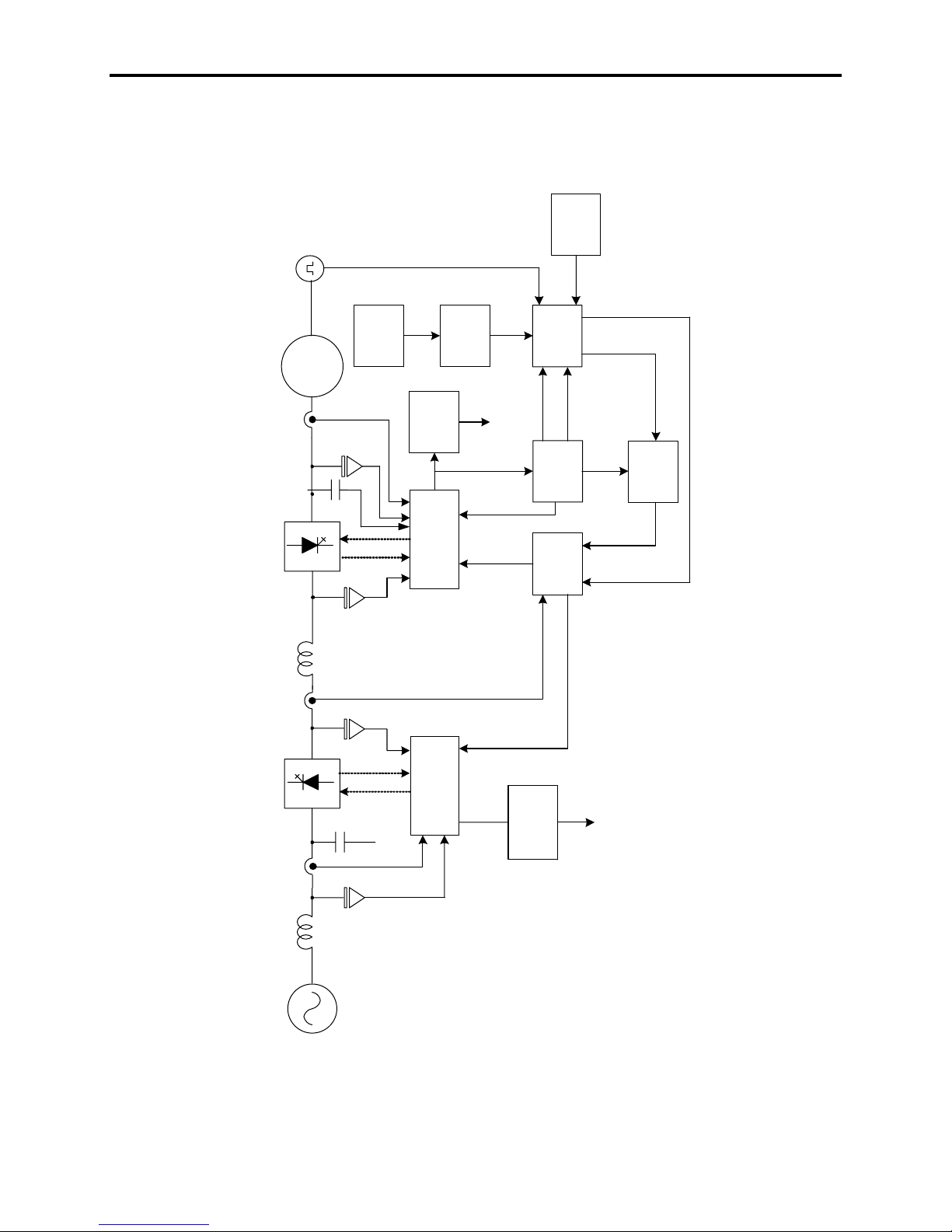
Description of Operation A complete block diagram of the PF7000 control circuit is shown in
Figure 1.1. The major blocks are described in the following sections.
Sync
Tach
Feedback
Transfer
Machine side
Machine
feedback and
Speed
Protection
Flux Range
gating
Reference
Faults
Alpha
Inverter
Alpha
Rectifier
Speed
Command
Motor
Motor
Current
Motor
Voltage
cap
Motor filter
Inverter
inductor
DCL ink
Speed
Control
Slip freq
Stator freq
Motor
Model
Control
Current
Idc Feedback
Flux Feedback
Inv Flux
CurCmd
InvTorque
CurCmd
Speed Feedback
Flux
Control
Rectifier
cap
Line filter
Reactor
AC Line
Figure 1.1 – Functional Block Diagram of PF 7000 control system
7000-TD002A-EN-P – September 2007
and gating
Line side feedback
Line
Current
LineVoltage
Source
Faults
Line
Protection
Page 7
Functional Description 1-3
Speed Command The function of Speed Command block is to select one of the 10
possible speed command inputs. Parameter Speed Ref Select (7) in
conjunction with Local/Remote selector switch is used to define the
speed command input Speed Command In (276). When the selector
switch is in Local position, the default speed command is the Analog
Speed Potentiometer typically mounted on the LV panel. When the
selector switch is in Remote position, the parameter Speed Ref Select
defines the source of speed command. The options available are:
Local ( Speed Potentiometer)
3 DPI commands ( DPIAdapter1, DPIAdapter2, DPIAdapter5)
2 Analog Inputs configured either for 0-10V or 4-20mA (Analog
Inp1, Analog Inp2)
3 Preset speeds (Preset Spd 1, Preset Spd 2, Preset Spd 3)
1 Preset Jog
In addition, the speed command can come from a built in PID
controller.
The above speed commands are used when the drive is in Normal
mode of operation. However PF7000 has many special modes of
operation e.g. test modes or auto-tuning for which different speed
commands are selected. Table 1.A summarizes the speed command
during these special modes.
Table 1.A – Speed Commands for special operating modes of PF7000
Special operating modes of PF7000 Speed Command In(276)
DC test mode Rated line frequency
Open Circuit Rated Line Freq (17)
Open Loop 0.1 x Rated Line Freq (17)
Rs autotune 2Hz
Ls autotune Rated Line Freq (17)
Flux Reg autotune Autotune Spd Cmd (213)
Speed Reg autotune Autotune Spd Cmd (213)
Sync transfer requested Bypass Frequency (159)
The selected Speed Command In is clamped to a minimum and a
maximum level by parameter Speed Cmd Max (290) and Speed Cmd
Min (293) to give Speed Command (277). The maximum value of
Speed Command cannot be greater than 125% of Base Speed (98).
Note: Contact the factory for applications that require output
frequencies greater than 125% of the motor base speed.
Contact factory for the availability of this feature.
7000-TD002A-EN-P – September 2007
Page 8

1-4 Functional Description
Speed Command (cont.) Three skip speeds Skip Speed 1(49), Skip Speed 2 (50), Skip Speed 3
(51) are provided to prevent the drive from continuously operating at
a certain speed. This feature is sometimes needed to avoid mechanical
vibrations occurring in a drive system at certain speeds. The skip
speed zone around each Skip Speed is specified by the parameter
Skip Speed Band1 (53), Skip Speed Band2 (54), Skip Speed Band3
(55) If the desired Speed Command lies in a given skip speed zone,
the Speed Command is clamped to the lowest value in the zone.
Example
If Skip Speed 1 is 45 Hz with Skip Speed Band1 as 1 Hz, then the
skip speed range extends from 44.5 Hz to 45.5 Hz. If the desired
speed command is set to 45 Hz, then the drive will avoid this speed
and run at 44.5 Hz.
The final stage in processing the command is the whether the drive
has been requested to run forward or reverse. The sign is changed if
reverse rotation is selected. The Speed Command is set to zero if the
drive is stopped.
Speed Reference The function of the Speed Reference block is to determine the Speed
Reference (278) from the desired Speed Command (277). PF7000
provides two options:
• S-curve
• Linear Ramp
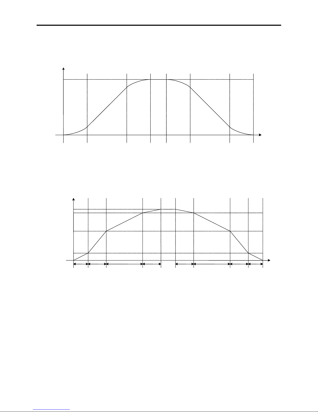
To select, S curve a non-zero value of S curve Percent (475) is
selected. Using parameter S curve Acc1 (481), the drive
automatically calculates the linear and the non-linear portions of the
S curve as shown in Figure 1.2. Following example shows how to
use S curve parameters:
Example
If S curve Accel 1 is set for 20 sec with 20% in S curve Percent, then
The parameters for deceleration are calculated using parameter S curve
Linear Ramp is enabled if the S curve Percent is set to zero.
7000-TD002A-EN-P – September 2007
the total acceleration time is increased by 0.2 x 20 = 4 seconds. The
total acceleration time will now be 24 seconds with 4 seconds in the
non-linear portion of the S curve. Since the curve is symmetrical,
each of the segments will be of 2 seconds duration.
Decel 1 (479) and S curve Percent (475) and shown in Figure 1.2.
Independent four section ramps are provided for acceleration and
deceleration. The ramp is specified by 4 Ramp Speeds, 4 Accel and
Decel times and is shown in Figure 1.3.
Page 9
Functional Description 1-5
0.005*
0.005*
S Curve Acc1
S Curve Acc1
*S Curve
*S Curve
Percent
Percent
S Curve Acc1
S Curve Acc1
(481)
(481)
0.005*
0.005*
S Curve Acc1
S Curve Acc1
*S Curve
*S Curve
Percent
Percent
0.005*
0.005*
S Curve Dec1
S Curve Dec1
*S Curve
*S Curve
Percent
Percent
S Curve Dec1
S Curve Dec1
(479)
(479)
0.005*
0.005*
S Curve Dec1
S Curve Dec1
*S Curve
*S Curve
Percent
Percent
Ramp Speed4
Ramp Speed4
(76)
(76)
Ramp Speed3
Ramp Speed3
(75)
(75)
Ramp Speed2
Ramp Speed2
(74)
(74)
Ramp Speed1
Ramp Speed1
(73)
(73)
Non-Linear
Non-Linear
Portion
Portion
Accel
Accel
Time1
Time1
(65)
(65)
Linear Portion
Linear Portion
Accel
Accel
Time2
Time2
(66)
(66)
Non-Linear
Non-Linear
Portion
Portion
Non-Linear
Non-Linear
Portion
Portion
Figure 1.2 – Speed Reference: S-curve
Accel
Accel
Time3
Time3
(67)
(67)
Accel
Accel
Time4
Time4
(68)
(68)
Decel
Decel
Time4
Time4
(72)
(72)
Linear Portion
Linear Portion
Decel
Decel
Time3
Time3
(71)
(71)
Non-Linear
Non-Linear
Portion
Portion
Decel
Decel
Time2
Time2
(70)
(70)
Decel
Decel
Time1
Time1
(69)
(69)
Figure 1.3 – Speed Reference: Linear Ramp
7000-TD002A-EN-P – September 2007
Page 10

1-6 Functional Description
Speed Control
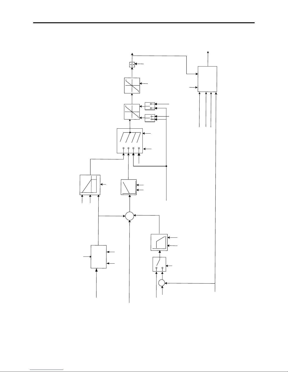
In Sensorless operation, the Slip Frequency is subtracted from the
In Sensorless mode, the drive uses TrqCmd0 Sensrlss (86) and
Depending open the application, a drive can be configured in
The function of the speed control block is to determine the torque-
producing component (I
) of the stator current (Is). The inputs to the
sq
block are the Speed Reference (278) from the speed ramp and the
Stator Frequency (448) and Slip Frequency (343) from the motor
model. If drive is installed with an optional tachometer, then the
motor speed is determined by counting the tach pulses.
Stator Frequency and filtered to determine the Speed Feedback
(289). In Pulse Tach mode, the speed is determined directly by using
Tach Feedback (349). The Speed Feedback is subtracted from the
Speed Reference to determine the Speed Error (472) which is
processed by the speed PI regulator. The gains of the regulator are
based on the Total Inertia (82) of the system and the desired Spdreg
Bandwidth (81). The output of the speed regulator is the Torque
Reference (291) whose rate of change is limited by Trq Rate Limit
(83). The calculated Torque Reference is divided by the Flux
Reference (305) and motor constant to determine the torque
component of the stator current MtrTorque CurCmd (292). To
calculate the torque producing current supplied by the inverter
InvTorque CurCmd (294), the current supplied by the motor filter
capacitor in torque production (orthogonal to motor flux) is
calculated and subtracted from MtrTorque CurCmd.
TrqCmd1 Sensrlss (87) for an open loop start up. At frequencies
greater than 3Hz, the drive enables the speed loop and disables the
open loop start mode. In Pulse Tach mode, the drive is always in
closed loop. The maximum torque a drive can deliver in motoring
mode is determined by Trq Lmt Motoring (84). In regenerative mode
the torque is limited to Trq Lmt Braking (85). It should be noted that
at speeds above the Base Speed (98), the motor torque capability is
de-rated and varies in inverse proportion to the speed (constant
power range).
different torque control modes by setting the parameter Trq Control
Mode (90). E.g. in stand-alone drives the parameter is set as Speed
Reg allowing the drive to be in speed control mode and regulating
the torque in the motor. In torque follower applications like
conveyors, one of the drives (Master) is set in Speed Reg mode
which enables the speed regulator while the other drives (torque
followers) are set in Trq Cmd External mode. The torque reference
produced by the Master drive is then passed on to the torque follower
drives by Trq Cmd External (91). Figure 1.4 shows other various
modes of operation.
7000-TD002A-EN-P – September 2007
Page 11
Functional Description 1-7
e
(291)
Torque Referenc
MODE
TORQUE
CONTROL
OL
z
H
(OL)
OPEN LOOP START
TrqCmd1 Se ns rLss (87)
TrqCmd0 Se nsrLss (86)
(475)
S Curve P e rcent
3
Speed Reference (278)
SPEED
REFERENCE
(292)
CurCmd
MtrTorque
LIMIT
TRQ RATE
LIMIT
TORQUE
2,5 (S,T)
(OL,S)
1,3,4,5(S ,T )
SPEED
REGULATOR
(472)
Speed Error
+
+
Max
(290)
Speed Cmd
Min
(293)
Speed Cmd
Flux
(305)
Reference
Trq Rate
Limit (83)
Trq
(90)
Mode
Control
4
3
0
0
Mode
Speed Fbk
Trq Control
(82)
Total
Inertia
(81)
Spdreg
Bandwidth
Trq Lmt
Trq Lmt
(89)
(90)
Mode
Trq Cmd External (91)
(310)
Mtr Flux
CurCmd
(85)
Braking
(84)
Motoring
Trq Control Mode (90)
0: ZeroTorque
-
(289)
Speed
Feedback
FILTER
SPEED
FEEDBACK
SELECT
T
SPEED MODE
S
+
-
(81)
Spdreg
Bandwidth
Filter (110)
Speed Fbk
Mode (89)
Speed Fbk
(294)
CurCmd
InvTorque
CAP
CURRENT
CALCULATOR
R Stator (129 )
LTota l Leakage (130)
Motor Fil ter Cap (128)
1: Speed Reg
2: Ext Trq Cmd
3: Spd Trq Pos
4: Spd Trq Neg
5: Spd Sum
Speed Fbk Mode (89)
S: Sensorless
T: Pulse Tach
Speed Command In (276)
Synch Reg Out put (298)
Tack Feedback (349)
Slip Frequency
Figure 1.4 – Speed Control
(343)
Stator Freq (448)
7000-TD002A-EN-P – September 2007
Page 12

1-8 Functional Description
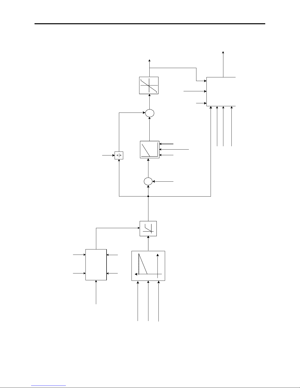
Flux Control The function of the flux control block (Figure 1.5) is to determine the
magnetizing component (I
maintain the desired flux profile in the motor. The inputs are Flux
Feedback (306) and Stator Freq (448) from the motor model, Speed
Feedback (289) and Torque Reference (291) from the speed control
block and the measured voltage at the input of the rectifier, Rec
Input Volt (696).
The Flux Feedback is subtracted from the Flux Reference (305) to
determine the Flux Error (307), which is the input to the flux PI
regulator. The gains are determined from desired Flxreg Bandwidth
(97) and motor parameters T Rotor (132) and Lm Rated (131). The
output of the flux regulator is FluxCurRegulator (309). An open loop
estimate of the magnetizing current FluxCur Feedfwd (308) is
determined by dividing the Flux Reference by parameter Lm Rated.
FluxCur Feedfwd and FluxCurRegulator are added to produce Mtr
Flux CurCmd (310) which is the magnetizing component of the
stator current command. To calculate the magnetizing current
supplied by the inverter Inv Flux CurCmd (312), the current supplied
by the motor filter capacitor in magnetizing is calculated and
subtracted from Mtr Flux CurCmd. It should be noted that as the
motor speed increases, Inv Flux CurCmd decreases. This is because
as the motor voltage increases more of the magnetizing current
requirement of the motor is met by the capacitor. At resonant point,
Inv Flux CurCmd is nearly zero and becomes negative at speeds
above resonance. InvTorque CurCmd (from Speed Control block)
and Inv Flux CurCmd are then passed to the Current Control block to
determine the dc link current reference (Idc Reference) and the firing
angles of the two converters (Alpha Rectifier and Alpha Inverter).
The flux profile in the drive is adjusted by the parameters Flx Cmd
No Load (103) and FlxCmd RatedLoad (100). Using these
parameters, Flux Reference is adjusted linearly with the desired
Torque Reference. At light loads motor flux is decreased allowing
reduction in losses while full flux is produced at rated load. The
maximum flux reference is limited to Flux Cmd Limit (623). This
limit is dependent on the Rec Input Volt
Feedback). If the drive operates at reduced line voltage, then Flux
Reference is reduced. Also if the motor is running above the Base
Speed, the flux profile is made inversely proportional to the speed of
the motor resulting in the field weakening or the constant power
mode of operation of the drive. This is accompanied by a decrease in
the motor torque capability.
) of the stator current (Is) needed to
sd
and the motor speed (Speed
7000-TD002A-EN-P – September 2007
Page 13
Functional Description 1-9
(310)
MtrFlux CurCmd
1.0
LIMIT
CURRENT
EXCITATION
-1.0
+
+
(448)
Stator
Frequency
(292)
CurCmd
MtrTorque
(312)
InvFlux CurCmd
CAP CURRENT
CALCULATOR
(309)
FluxCur
(98)
(289)
FLUX
Regulator
T Rotor (132)
(131)
REGULATOR
(307)
Flux Error
-
+
Flux
(305)
Reference
FLUX
Flxreg
Flux
LIMIT
Lm Rated
(97)
Band width
(306)
Feedback
(308)
FluxCur Feedfwd
(131)
Lm Rated
(623)
Flux Cmd Limi t
Base
Volt (18)
Rated Line
LIMIT
FLUX
COMMAND
Volt ( 22)
Rated Motor
Speed
Speed
Feedback
R Stator (129)
LTotal Leak age ( 130)
Motor Filt er Cap (128)
(696)
Rec InputVolt
FlxCmd No Load (103)
FlxCmd Rated Load (100)
Torque Reference (291)
Figure 1.5 – Flux Control
7000-TD002A-EN-P – September 2007
Page 14

1-10 Functional Description
Flux Control for Synchronous
Motor
Most of the magnetization for a synchronous motor is supplied by
the rotor field winding, unlike an induction motor where all of the
magnetizing current is supplied through the stator. However, control
of the motor flux through the field current is very slow because of
the large time constant of the dc field winding and the current and
voltage limitations of the field supply. To obtain sufficiently fast
response from the flux regulator the magnetizing current is split into
transient and steady state components, with the steady state
component supplied through the rotor and the transient component
through the stator.
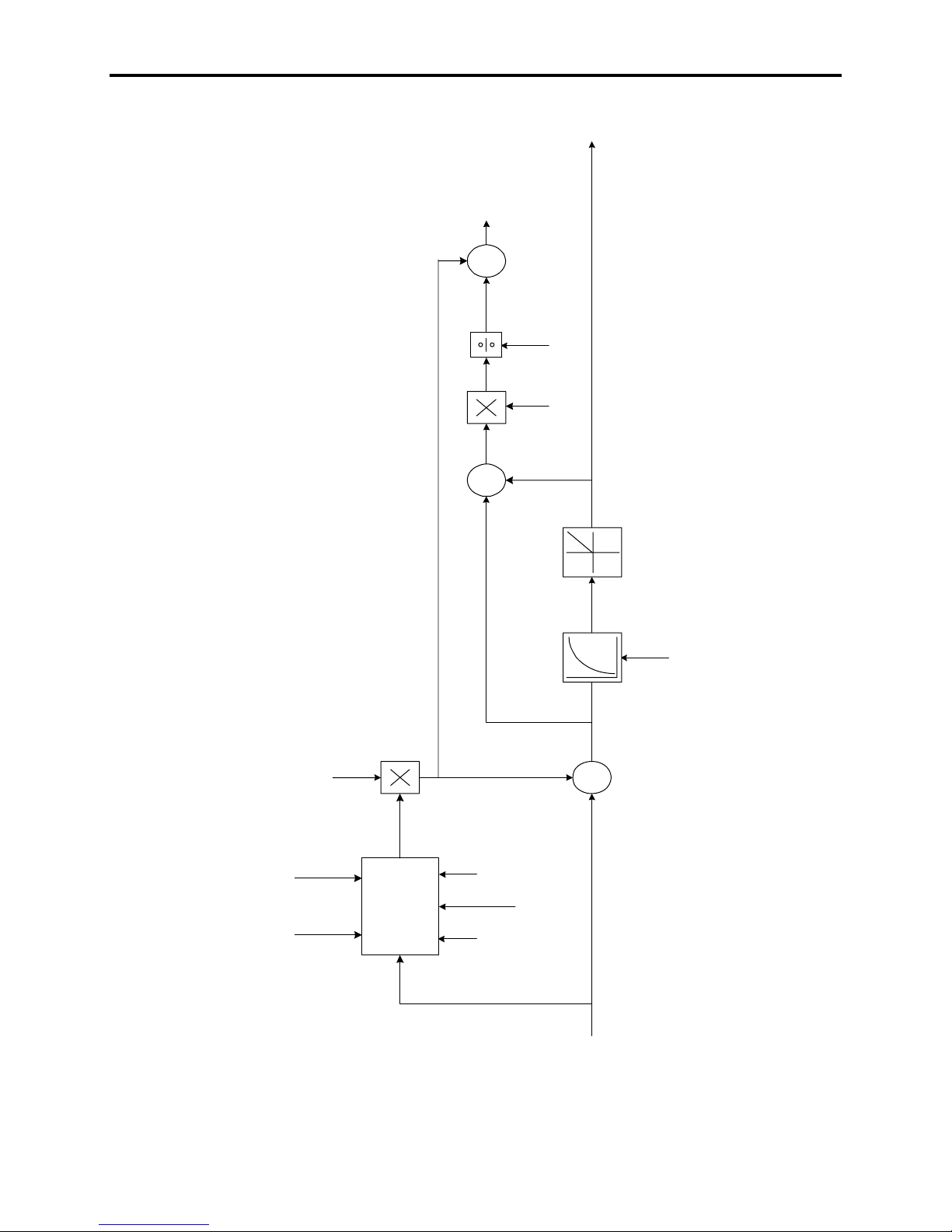
The additions to the flux control required for synchronous machines
are shown in the block diagram (Figure 1.6). The portion of the
motor filter capacitor current supplied by the drive is then added to
determine Inv Flux CurCmd, which is the magnetizing component of
the dc link current command.
Parameter Icd Command Gain (107) determines how the motor filter
capacitor current is split between the motor and the drive. When this
parameter is set to its minimum value of 0.0, all the capacitor current
is supplied by the drive. The line current is higher than the motor
current and the motor operates at approximately unity power factor.
When this parameter is set to its maximum value of 1.0, the motor
supplies all the capacitor current. The line current is less than the
motor current and the motor operates at a lagging power factor with
reduced field current.
Contact factory for the availability of synchronous motor control.
7000-TD002A-EN-P – September 2007
Page 15
Functional Description 1-11
(312)
InvFlux CurCmd
+
+
-
+
Lmd
Lm Rated
(314)
Field CurCmd
(418)
(131)
FILTER
LOWPASS
-
Gain (107)
Icd Command
Flux
(305)
Reference
CALCULATOR
(448)
Stator
Frequency
CAP CURRENT
(130)
LTotal Leakage
Motor Filter
(131)
Lm Rated
+
Cap (128)
(131)
Mtr Flux CurCmd
(106)
Field Bandwidth
Figure 1.6 – Flux Control for Synchronous Motor
7000-TD002A-EN-P – September 2007
Page 16

1-12 Functional Description
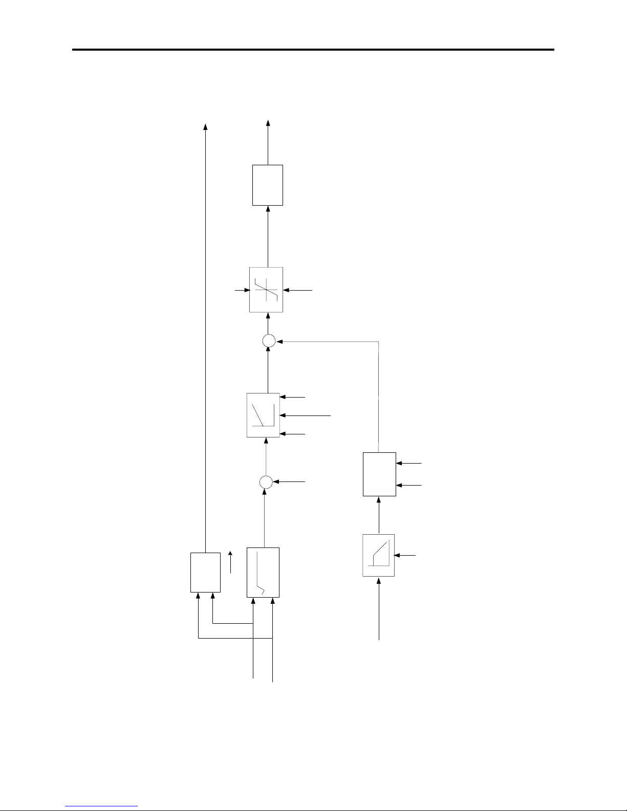
Current Control The function of the current control block (Figure 1.7) is to determine
the firing angles for the converters Alpha Rectifer (327) and Alpha
Inverter (328). The inputs are the torque (InvTorque CurCmd) and
flux producing (Inv Flux CurCmd) components of the dc link current
command from the speed control and flux control blocks respectively,
and the measured dc link current Idc Feedback (322).
The square root of the sum of the squares of Inv Flux CurCmd and
InvTorque CurCmd determines the dc link current reference Idc
Reference (321). This is subtracted from the measured dc current
feedback is subtracted to determine Idc Error (323). This is
processed by the current regulator to produce Vdc Error (332). To
effectively control the dc link current an estimate of the motor side
dc link voltage is done to calculate Vdc Feedfwd (333) which is
added to Vdc Error to produce the reference voltage for the line side
converter Vdc Reference (326). The line converter firing angle is the
inverse cosine of Vdc Reference. The machine converter firing angle
is determined by taking the inverse tangent of the ratio of Inv Flux
CurCmd to the InvTorque CurCmd. The quadrant of operation is
adjusted based on the signs of the current commands.
7000-TD002A-EN-P – September 2007
Page 17
Functional Description 1-13
(327)
Alpha Rectifier
-1
cos
-
1
(328)
Alpha Inverter
(326)
Vdc Reference
Retard Limit
+
+
(332)
Vdc Error
DC LINK
CURRENT
REGULATOR
(323)
Idc Error
-
+
(321)
Idc Reference
-1
tan
2
+y
2
x
Curreg
Bandwidth
T DC link
Idc feedback
(322)
Advance Limit
(115)
(113)
DCLnk
Inductance
FEEDFORWARD
(27)
FILTER
(333)
Vdc Feedfwd
cos
(135)
Line Voltage pu
(328)
Alpha Inverter
(502)
Feedforward Fil
InvFlux
CurCmd
(312)
CurCmd
InvTorque
(294)
Figure 1.7 – Current Control
(344)
Stator Voltage
7000-TD002A-EN-P – September 2007
Page 18

1-14 Functional Description
Line Converter Feedback The function of the line converter feedback block is to process (scale
and filter) the liner side voltage and current feedback signals to the
form required by the drive control software. The circuitry for
realizing this is built in the Analog Control Board (ACB).
The first Voltage Sensing Board (VSB) provides three line voltage
feedback signals (V
(V
, VL-) and one line side filter capacitor voltages referenced to
L+
ground. The three line-to-ground voltages are subtracted from each
other to produce the three line-to-line voltages (V
of those line voltages (V
software for synchronization and protection. The three line voltages
are used to find the peak input voltage (V
compared with trip setting (V
voltage protection. In PWM drives, the neutral point of the line filter
capacitor is measured (V
voltage protection. The two dc voltages are subtracted to determine
the line side dc link voltage (V
drive.
Current transformers (CT) in two of the ac input lines provide the
input line current feedback (I
current feedback signals reproduces the current in the remaining
phase. A Hall Effect Current Sensor (HECS) is used for monitoring
the dc link current and used for hardware overcurrent protection. In
addition the average value of the dc link current feedback is
measured using a V-f converter and used by the dc link current
controller to calculate the firing angle for the rectifier.
The preceding description applies to 6-SCR and PWM rectifier
options. For drives with the 18 pulse front-end, another VSB is daisy
chained with the first one providing additional six line-to-ground
voltages from the slave bridges. The slave 1 voltages are monitored
using (V
(V
4uv
I
and I4u, I4w are also brought in for protection. As in 6-pulse drives,
3w
, V
4vw
3uv
, V
, V
3vw
4wu
inverting and adding the two current feedback signals reproduces the
current in the remaining phase. Also for 18-pulse drives, the three ac
line-to-ground voltages are summed together to determine the neutral
to ground voltage on the input transformer.
, V2v, V2w), the second VSB provides two dc
2u
, V
, V
2uv
, V
2uv
n1
, V
) while slave 2 voltage are monitored using
3wu
) are filtered and sampled by
2vw
). This value is then
2-pk
) for instantaneous hardware ac over
ltrp
) and used for line side neutral over
), which is then sampled by the
dcr1
, I2w). Inverting and adding the two
2u
2vw
). Two
2wu
). In addition current feedback from slave bridges I3u,
7000-TD002A-EN-P – September 2007
Page 19

Functional Description 1-15
Machine Converter Feedback The function of the machine converter feedback block is to process
(scale and filter) the motor side voltage and current feedback signals
to the form required by the drive control software. The circuitry for
realizing this is built in the Analog Control Board (ACB).
vws
, V
, Vv,
u
wus
).
The first VSB provides three motor voltage feedback signals (V
V
), the second VSB provides two dc (VM+, VM-) and one machine
w
side filter capacitor neutral voltage referenced to ground. The motor
line-to-ground voltages are subtracted from each other to produce the
three motor line-to-line voltages (V
voltages (V
, Vvw ) are filtered and sampled by software for
uv
, Vvw, Vwu). Two of those
uv
synchronization and protection. The three line voltages are used to
find peak voltage (V_
(V
) for instantaneous hardware ac over voltage protection. The
mtrp
). This value is then compared with trip setting
pk
motor line-to-ground voltages are summed to determine the motor
neutral-to-ground voltage (V
) and is used for motor neutral over
zs
voltage protection. In addition, the neutral point of the motor filter
capacitor is measured (V
) and used for motor side neutral over
n
voltage protection. The two dc voltages are subtracted to determine
the machine side dc link voltage (V
), which is sampled by the
dci1
drive.
Two Hall Effect Current Sensor (HECS) provide stator current
feedback from two of the motor phases (I
, Iw). Inverting and adding
u
the two current feedback signals reproduces the current in the
remaining phase. The drive control software uses the sampled
voltages and currents to determine the motor flux and uses it for
synchronization.
For drives with Synchronous Transfer option, an additional VSB is
used for sensing three line-to-line bypass voltages ( V
Two of these (V
uvs
, V
) are further filtered and sampled by the
vws
uvs
, V
software for synchronizing the drive output voltage to the bypass
voltage.
If drive is installed with an optional tachometer, the board is plugged
into the J28. The motor speed is then determined by counting the
tach pulses in the FPGA on the DPM.
7000-TD002A-EN-P – September 2007
Page 20

1-16 Functional Description
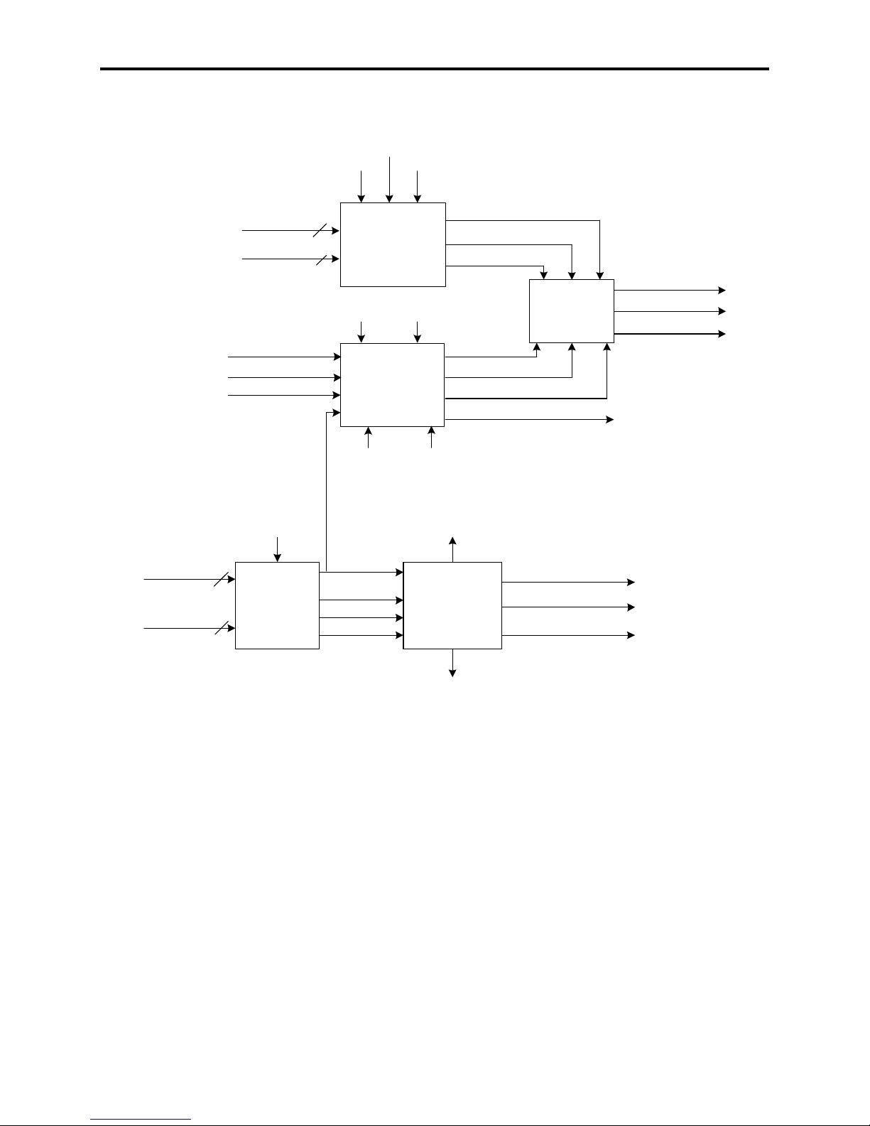
Motor Model The function of the motor model block (Figure 1.8) is to determine
the rotor flux position (Flux Angle), flux feedback (Flux Feedback),
applied stator frequency (Stator Freq), slip frequency (Slip
Frequency) and motor operating variables like stator current (Stator
Current), stator voltage (Stator Voltage), torque (MtrAirGap
Torque), power (MotorAirGap Power) and power factor (Mtr Pwr
Factor).
The PowerFlex 7000 uses Rotor Flux oriented control to achieve
independent control of motor flux and torque. This is achieved by
synchronizing the machine converter gating to Flux Angle. To
determine the flux feedback, stator frequency and the synchronizing
reference frame the drive uses either the Voltage or the Current
model. For speeds greater than 3Hz, the drive uses the voltage model
(from measured motor voltage and current) to calculate the Flxfbk
VoltModel, and StatFreq VoltModel. Below 3Hz, the drive uses the
current model to calculate Flxfbk CurModel, and StatFreq
CurModel. The current model is based on indirect vector control and
uses the d-q components of stator current along with motor
parameters T Rotor and Lm Rated. Based on the operating speed of
the drive and the speed feedback mode (Sensorless or Pulse Tach), a
flux select algorithm determines the model to be used. Motor model
also calculates the Slip Frequency which is used in the calculation of
the motor speed (Speed Control) in Sensorless mode and for
determining the rotor flux position in Pulse Tach mode.
The synchronously rotating frame (Flux Angle) is used in
transforming the measured motor currents and voltages into d-q
components. The direct axis components are in phase with the rotor
flux, while the quadrature axis components are displaced 90 degrees
from the rotor flux. The stator current (Stator Current) and voltage
magnitudes (Stator Voltage) are calculated by taking the square root
of the sum of the squares of the respective d-q components. The
motor Torque is calculated by multiplying the Flux Feedback and I
with motor torque constant. Torque multiplied by the motor speed
gives the Mtr AirGap Power. Mtr Power Factor is determined as the
ratio of motor active power and the apparent power.
sq
7000-TD002A-EN-P – September 2007
Page 21
LTotal Leakage
R Stator
(129)
(130)
Lm Rated
(131)
Functional Description 1-17
LTotal Lea kage
(130)
MotorVoltages
Motor Currents
Motor Currents
Motor Voltages
Tach Feedback (349)
Speed Reference (278)
T Rotor (132)
MtrFlux Current
(338)
FluxAngle
3
VECTOR
ROTATOR
3
3
VOLTAGE FLUX
3
Rotor Angle
CURRENT FLUX
MtrFlux
CurCmd
(310)
Mtr Trq
Current (339)
V
sd
V
sq
MODEL
Flux Ref er e nc e
MODEL
MtrTorque
CurCmd
Stator Current (340)
FlxFbkVoltM odel (342)
StatFrqVoltModel (485)
FluxAngle V
(305)
FluxAngle C
StatFrq C ur M o del ( 486 )
FlxFbk CurModel (341)
Slip Frequency (343)
(292)
MOTOR
OPERATING
VARIABLES
FLUX
SELECTOR
MtrAirGap Power (346)
Mtr Power Factor (692)
MtrAirGap Trq (345)
Flux Feedba c k (306)
Stator Fr eq ( 448)
FluxAngle
StatorVoltage (344 )
Figure 1.8 – Motor Model
Drive/Motor Protection
Except for the dc link overcurrent, rectifier over voltage and inverter
The response to a drive alarm falls into three categories:
over voltage, the entire drive protection is realized in the software.
Adjustable parameters specifying the trip level and time delay are
provided for each fault. A detailed list of all the faults and warnings
(alarms) is provided in Chapter 3 – Troubleshooting.
7000-TD002A-EN-P – September 2007
Page 22

1-18 Functional Description
Drive/Motor Protection
For Class 1 faults (with the exception of dc link overcurrent,
(cont.)
The dc link overcurrent, rectifier input overvoltage and inverter
For Class 2 faults the motor is brought to a normal stop before the
For most Warnings no action is taken and drive maintains its normal
It is important to understand how contactors (input and output)
An output contactor, whose configuration is specified by Output
rectifier overvoltage and inverter overvoltage), the line converter is
immediately phased back to retard limit until the dc link current
drops to zero. The gating for both converters is disabled and the
contactors (if installed) are opened. At this point the motor will coast
and its speed will depend on the characteristics of the load. For some
high inertia loads, the motor may coast for a long time.
output voltage are special cases in that the fault detection is
performed by hardware because a very f a s t r e s p o ns e i s r e q ui r e d. T h e
hardware fault detection responds to instantaneous values. Also the
drive response to these faults is different from other Class1 faults
because it freezes the SGCT gating (both converters if a PWM
rectifier based drive and only the inverter side if a 6P/18P SCR
drive) until the dc link current has dropped to zero. The gating is
then disabled and contactors are opened.
gating is disabled and the contactors opened. Typical examples of
Class 2 faults are motor overload, drive overload and loss of load.
operation. A warning could be an indication of a problem in drive
e.g. an Air Filter warning is an indication of a blocked air filter. In
addition there are a few warnings in the drive that may cause
momentary interruption in the operation of the drive e.g. Master UV,
Line Loss or Bus Transient. The action taken is similar to a Class1
fault and the normal operation is resumed once the transient
condition has disappeared. If a drive experiences Master UV or Line
Loss, then Auto Restart Dly (3) should be set to a non-zero value in
order to resume normal operation automatically.
behave in an event of fault. If the input contactor is set for Not
Running or All Faults via parameter Input CtCtr Cfg (1), then the
contactor opens on any fault (Class 1, Critical or Class 2) in the
drive. This happens after the dc link current has been brought to zero
and the gating for all converters disabled. If the contactor is set for
Critical Flt, then the contactor will open only when a critical fault
(explained above) happens in the drive. For all other faults (Class1
or Class2) the input contactor will remain closed after the drive has
been shut off. For a complete list of fault classification, refer to
Chapter 3 – Troubleshooting.
Ctctr Cfg (5), opens for any fault in the drive. This happens after the
dc link current has been brought to zero and the gating for all
converters disabled.
7000-TD002A-EN-P – September 2007
Page 23
Functional Description 1-19
Power Semiconductor
The PowerFlex 7000 drive tests for the failure of the power
Diagnostics
semiconductors (SCRs or SGCTs) before running and while running.
The method used to detect failed devices is different for starting
(offline diagnostics) and for running (on-line diagnostics), but the
same hardware is used in both situations. The drive control receives
a feedback signal via a fiber-optic cable from each device gate
driver, which can indicate whether or not it is healthy. SCR
diagnostics are based on sensing the voltage across the device while
SGCT has smart diagnostics built in the gate driver board. The
feedback and the gating have a certain relationship when the device
is healthy or failed. This is shown in Figure 1.10 and will be
described in detail in following sections. The description applies to
all 6P, 18P and PWM PowerFlex 7000 drives. In the drive, the test
points are available on the OIBB for monitoring the gating and
diagnostic signals. In order to understand how the diagnostics work,
it is important to understand the relationship between fiber optic
signals and the logic levels on the test points. This is summarized in
Table 1.B and Table 1.C.
Table 1.B
OIBB Transmitter(TX) TP_CMD on OIBB Device Status
LIGHT 0V ON
NO LIGHT 5V OFF
Table 1.C
OIBB Receiver(RX) TP_DIAG on OIBB
LIGHT 0V
NO LIGHT 5V
7000-TD002A-EN-P – September 2007
Page 24

1-20 Functional Description
Off-line Detection of Failed SCRs/SGCTs
Power Semiconductor
Diagnostics (cont.)
The rectifier diagnostics are performed when medium voltage is
For SCR rectifiers, when the line voltage is applied to the drive
Line Converter – 6P-SCR, 18P-SCR and PWM
first applied by closing the input contactor and when the drive
receives a start command. The drive also performs off line
diagnostics when a drive reset command is issued. These
diagnostics are capable of detecting a bad device, loss of
feedback fiber optic and loss of gating fiber optic. The
diagnostics consist of two stages. A passive diagnostic test
followed by an active diagnostic test. In the passive diagnostics
test no devices are gated.
SCR Rectifier Passive Off-Line Diagnostics
but the drive is not running, the voltage across the line converter
thyristors is high and positive for half cycle except during
intervals around the zero of the line voltage. The gate driver
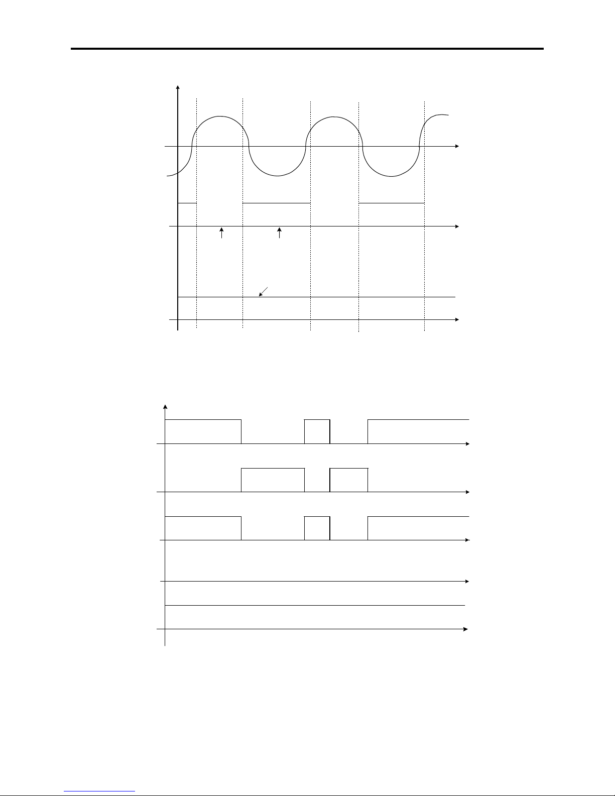
transmits light whenever the device is forward biased with a
large enough voltage as shown in Figure 1.9. On the OIBB
diagnostic test point this translates into a feedback signal at 0V
level. Since the drive is not gating (no light, 5V signal on the
OIBB gating test point) the feedback normally toggles state
every cycle of the utility voltage. However the feedback will not
toggle state if the device is shorted, or if the feedback fiber-optic
path is incomplete. This is shown in Figure 1.9. If this occurs,
the drive faults and issues an OfflineShrt fault for the device.
PWM Rectifier Passive Off-Line Diagnostics
For PWM rectifiers the transmitter on the device should send a
light back when the device is healthy (0V on the diagnostic test
point). However the light signal will not be received if a device is
shorted or if the feedback fiber-optic path is incomplete. The
drive presumes the device has failed and determines which
devices would be safe to gate for the more detailed active offline
diagnostic test.
7000-TD002A-EN-P – September 2007
Page 25
+5V
Typ
GCT
G
ern
Functional Description 1-21
Voltageacross a thyristo rwhenmedium voltage is applied
Diagnostic feedback
for a healthySCR
0
Diagnostic
feedback low
+5V
0
Diagnostic
feedback high
Diagnostic feedback
for a sho rtedSCR
NoLight
Figure 1.9 – Voltage across a thyristor when MV is applied
+5V
+5V
+5V
+5V
+5V
0
0
0
0
0
NO LIGHT
(DeviceOff)
LIGHT NO LIGHT
NO LIGHT LIGHT
LIGHT
(DeviceOn)
Gate Cathode shortedor PS problem
ical S
Healthy DiagnosticFeedback
No gating received
LIGHT
No diagnostic feedback
NO LIGHT
atingpatt
Figure 1.10 – SGCT diagnostics
7000-TD002A-EN-P – September 2007
Page 26

1-22 Functional Description
Power Semiconductor
Diagnostics (cont.)
In the active diagnostic test, each device is gated at maximum
For the PWM rectifier, the active diagnostic test can differentiate
SCR Rectifier Active Off-Line Diagnostics
blocking voltage. For a healthy SCR, the feedback will normally
change from high to low when gated. However the drive will
receive a high state (light) both before and after gating if the
device is open-circuited, there is an incomplete gating fiber-optic
path or a damaged gate driver. When this occurs the drive will
issue an Offline Open fault for the device. If the drive receives a
low signal (no light) in both states, there may be shorted device
or an incomplete feedback fiber optic. If this occurs drive will
issue an Offline Shrt fault for the device. Failed or open-circuited
snubber connections will shift the device blocking voltage (when
not running) which may case either fault to appear. It should be
noted that during the active diagnostics stage a dc link voltage
which is close to rated voltage will appear due to interaction with
the snubber circuit.
PWM Rectifier Active Off-Line Diagnostics
between a failed device and a broken fiber-optic path because the
gate driver toggles the feedback differently when gated as shown
in Figure 1.10. As in the SCR rectifier active offline diagnostics,
each device is gated at peak blocking voltage (if MV is available).
Devices which could cause a line to line short circuit are not
gated. If the drive detects a failed device, an Offline fault is
issued for the device. A weak gate power supply may also cause
a device fault. If the drive receives no light signal (5V on the
diagnostic test point) both before and after gating, then there
may be an incomplete feedback fiber-optic and a DiagFkbLoss
fault will be issued. A completely failed or unplugged power
supply will also cause this fault. If the drive always receives a
light signal (0V on the diagnostic test point) both before and
after gating, the device may not have received the gating signal
and a Gating Loss fault will be issued. The drive will not allow
the contactor to be closed if it detects enough failed devices to
cause a line to line short circuit.
Machine Converter off line diagnostics
The inverter diagnostics are performed when the drive control is
The inverter off-line diagnostics are similar to the PWM rectifier
7000-TD002A-EN-P – September 2007
powered up and when the drive receives a start command. The
drive also performs off line diagnostics when a drive reset command
is issued. These diagnostics are capable of detecting a bad device,
loss of feedback fiber optic and loss of gating fiber optic.
diagnostics except that: no passive diagnostic is done, no
consideration is given to line-to-line short-circuits and the input
contactor is not involved. The inverter off-line diagnostics will
generate Device Flt Fbk FO Loss and Gat FO Loss faults.
Page 27

Functional Description 1-23
On-line detection of Failed SCRs/SGCTs
When the gating is enabled for both converters, the feedback from the
gate drivers is constantly switching on and off, usually several times per
cycle. The diagnostics feedback signals from each device are monitored
and the protective measures are performed.
SCR On-Line Diagnostics
For SCR rectifier drives, the drive detects both open and shorted
devices while running. Due to notching and interaction with the other
phases, the SCR feedback diagnostic changes state many times per
cycle, although it is only valid just before and after firing the device.
Just before firing a device, the drive takes several samples of the
diagnostic feedback from the SCR. If every sample indicates that the
device was on before it was fired, the drive considers that the device
may be shorted, and starts a timer. When this timer exceeds the
number of line cycles specified by the parameter Rec Dvc Diag Dly
(266) the drive generates an OnlineShrt fault. Each device has its
own timer. A delay of zero will generate a fault immediately. A
delay of 2 will generate a fault after 2 cycles which indicates that the
fault has been seen three times in a row.
Shortly after the drive fires an SCR it checks the feedback from the
gate driver boards. If the feedback shows that the device did not fire
the drive considers that the device may be open-circuited and starts a
timer. If the fault persists for 6 cycles, the drive generates an
OnlineOpen fault. As with the short circuit fault, each device has its
own timer, however the delay is not adjustable.
Both on-line device diagnostics are not availabl e at all mod es of
operation due to the nature of the feedback from th e gate driv er.
No diagnostics are done when the rectifier firing angle is less than 15
degrees. No diagnostics are done when the dc current is discontinuous.
SGCT on-line diagnostics
The PWM rectifier and inverter generate only one type of on-line
diagnostic fault. Due to the intelligent gate driver board the drive is
able to check the status of every SGCT in a bridge any time a device
in the bridge is fired. The drive takes a sample of every device’s
feedback before and after firing the bridge. If both samples indicate
that the device is not functioning correctly the drive starts a timer for
that device. When this timer reaches the value specified by parameter
Rec Dvc Diag Dly (266) for the PWM rectifier, or Inv Dvc Diag Dly
(268) for the inverter, the drive generates an Online fault. The actual
time to trip will vary with the switching frequency of the bridge in
question. A bridge changes state at three times the switching
frequency. For a PWM rectifier switching at 420 Hz (7pulse at 60 Hz),
the bridge changes state at 1260 Hz. This means the delay is in
multiples of around 0.8 ms.
7000-TD002A-EN-P – September 2007
Page 28
1-24 Functional Description
Test Modes The PowerFlex 7000 AC drive is provided with test modes to check
the functionality of the drive during commissioning. These test
modes are selected using the parameter Operating Mode in the
Feature Select group. When Test Mode is set to the default value of
Normal, the drive is in the normal operating mode. The parameter
cannot be changed while the drive is running.
Setting Operating Mode to Gate Test allows the gating checks to be
performed on the rectifier and the inverter. Both the input and output
contactors must be open and medium voltage must not be applied to
the drive. This test is carried out in conjunction with two additional
parameters Inv Gating Test and Rect Gating Test. Upon selecting
Gate Test, both the parameters are automatically set to Test Pattern.
A brief description follows in this section.
Setting Inv Gating Test to Test Pattern will fire the inverter devices
in a sequential Z pattern at a low frequency (1Hz) and is verified by
observing the LEDs on the SGCT gate driver board. Setting Inv
Gating Test to Normal Gate will result in the inverter devices firing
as in normal mode of operation. The frequency of the gating is
controlled by parameter Speed Command In (276). Setting Inv
Gating Test to Off stops the inverter test gating sequence.
In 6 or 18-pulse SCR PowerFlex drives, the gate driver boards derive
power from medium voltage. Hence to check the line converter
gating in Gate Test mode where there is no MV available, a special
power harness is required. The line converter gating is quickly
checked by setting the Rect Gating Test to Test Pattern. This will fire
the rectifier devices in a sequential Z pattern at a low frequency (1Hz)
with only one device on at a time and is verified by observing the
LEDs on the SCR gate driver boards. To set the rectifier gating in
normal operation select Normal Gate. The SCR firing is at the input
line frequency.
For 6-pulse PWM drives, no power harness is required as the SGCTs
are powered by the Gate Power Supply.
7000-TD002A-EN-P – September 2007
S H O C K H A Z A R DS H O C K H A Z A R D
Disconnect all ends of cable before applying
medium voltage power. Failure to disconnect
cable before applying medium voltage can
result in damage to equipment, serious personal
injury or death.
Page 29
Functional Description 1-25
A T T E N T I O NA T T E N T I O N
Application of medium voltage to the drive
input or output when it is operating in gate test
mode may cause severe damage to the drive.
To test the line converter and to tune the dc link current regulator and
the line commutating impedance, the drive Operating Mode is
selected as DC Current. In this test mode, the line converter
operates normally, but the machine converter gating is modified to
gate both the positive and negative legs in the same phase in order to
short-circuit the dc link current through the machine converter. The
short circuit current is slowly rotated among the three phases with
overlap between phases to ensure that an open circuit does not occur
during commutation. There is no current in the motor and the output
contactor (if installed in the drive) is opened. The dc current
command is set equal to the value specified by parameter Idc Test
Command (119) in the Current Control group. In this test mode the
line converter firing angle Alpha Rectifier (327) will be close to 90
degrees. This is because it takes very small dc voltage to build
current in a shorted dc link.
Setting Operating Mode to System Test selects the system test mode.
This mode is used to test the drive as a system, including interfaces
with external devices such as programmable controllers, without
applying power to the drive or motor. The drive behaves as if it was
running normally but device gating disabled. Since the input, output,
and bypass contactors operate normally in this mode, it must be
ensured that the drive and motor are isolated from medium voltage.
If the drive detects medium voltage in this test mode, a fault MV in
SystemTest is issued and the input contactor is opened.
A T T E N T I O NA T T E N T I O N
It is the responsibility of the operator to ensure
that the drive and motor are isolated from
medium voltage when the drive is operating in
system test mode with the input, output, and
bypass contactors closed.
Setting Operating Mode to Open Circuit, selects the open circuit test
mode. This mode is used to test the drives at rated output voltage
and frequency without connecting it to a motor. In open circuit test
mode, ac current sufficient to produce rated voltage at the drive
output is forced through the output filter capacitors. When the drive
is started in this mode, it ramps up to rated frequency and
synchronizes its output voltage with the line voltage. The current
reference is set to a value that will produce voltage at the drive
output set by the parameter FlxCmd RatedLoad (100).
7000-TD002A-EN-P – September 2007
Page 30
1-26 Functional Description
Test Modes (cont.)
A T T E N T I O NA T T E N T I O N
Open circuit test mode should not be used
when the drive is connected to a load unless
an output contactor is provided.
Setting Operating Mode to Open Loop selects a diagnostic mode
in which the drive is run in an open loop manner without closing any
of the feedback loops on the motor side (Speed and Flux regulators).
Parameters TrqCmd0 Sensrlss and TrqCmd1 Sensrlss are used to
inject motor current at a small stator frequency (typically 10% of
Rated Line Frequency). Motor will be turning in this mode and drive
analog flux feedback variables FlxFbk VoltModel (342) and
StatFrqVoltModel (485) are used to ensure the reliability of the
analog feedback.
This feature is available in drives running induction motors only.
Flying Start (Induction Motor)
1. The motor has pulled out and stalled during starting due to
Using this feature, the PowerFlex 7000 AC drive is capable of
restarting a motor that is not stationary but is already rotating. In
normal operation, the output of the drive is synchronized with the
motor flux which is derived from the stator voltage and current
feedback. Upon starting, if there is no detectable stator voltage, the
drive assumes that the motor is stationary. The output frequency
starts from an initial value of zero and ramps up until motor flux is
detected. Significant flux is created in the motor only when the slip
frequency (i.e. the difference between the applied stator frequency
and rotor frequency) is small. When the drive is started with the
motor stationary, the initial slip frequency is small and the motor
flux builds up fairly quickly. But, if the motor is already spinning,
then very little flux will be induced until the stator frequency is quite
close to the rotor frequency, at which time the motor flux will
suddenly rise to a level sufficient for the drive to detect and
synchronize. If the drive reaches the maximum allowable speed
command without detecting any motor flux, then it will trip on a
motor stall fault. There are following possible causes of a motor stall
when starting:
insufficient torque. The remedy for this is to increase the value
of some or all of the parameters TrqCmd0 Sensrlss, TrqCmd1
Sensrlss and Accel Time 1.
7000-TD002A-EN-P – September 2007
Page 31

Functional Description 1-27
2. The motor was already rotating but the flying start failed because
the drive passed through the low slip region too quickly to allow
the motor flux to build up. The solution to this problem is to
increase the value of parameter Accel Time 1. Most medium
voltage motors have a rotor time constant in the range of 1 to 5
seconds, and it can take a few seconds for the flux to rise to a
detectable level. Until flux is detected, the drive does not use the
normal speed ramp but continues to accelerate at the rate defined
by parameters Accel Time 1 and Ramp speed 1. If this rate exceeds
2Hz/sec, then the drive limits it internally to a maximum of 2Hz/sec.
3. The motor is rotating in the direction opposite to the commanded
direction of rotation. The slip frequency will increase instead of
decreasing as the drive accelerates and no flux will be induced in
the motor. In such cases, selecting Bidirectional flying start
feature, allows the drive to search the motor in opposite direction
before stalling. This option can be selected by enabling
in Special Features (99).
FlyStrt
BiDr
If the motor is coasting at a high enough speed (above about 40 Hz)
and the output contactor is closed, then the motor may self excite
with the drive motor filter capacitors and generate a high stator
voltage that the drive can detect. The drive will re-synchronize to
this voltage and quickly restart.
If the optional tachometer feedback is installed, then the drive knows
the speed of the motor at all times and can perform a flying start for
any speed or direction of rotation.
Flying Start (Synch Motor) With a synchronous motor, flying start is much quicker and more
reliable because a detectable stator voltage is produced whenever the
field is applied and the motor is rotating, even with zero stator current.
When the drive is started, rated field current is applied to the motor
but the stator current remains at zero until the end of the ramp start
delay to allow the rotor flux to build up. If the stator frequency is
greater than about 2 Hz, sufficient stator voltage is generated to
allow the drive to detect the speed and direction of the motor and
synchronize itself to the motor flux. If the flux feedback does not
reach a minimum level of 0.2pu, the drive assumes that the motor is
stationary and starts from zero frequency.
If an optional position encoder is installed, a flying start can be
performed for any speed or direction of rotation.
7000-TD002A-EN-P – September 2007
Page 32

1-28 Functional Description
Tachometer/Encoder Option The optional tachometer/encoder provides two significant
enhancements to the drive control:
1. Provides an accurate measurement of motor speed and direction
at all times
2. Extends closed loop speed and torque control down to nearly
zero speed.
A pulse tachometer, also called a pulse generator or incremental
encoder, produces a pulse train output with a frequency proportional
to shaft speed. By counting the number of pulses, the motor speed
can be determined. The tachometer is wired to an optional
tachometer board installed on connector J28 of the ACB.
Parameter Tach Type (233) specifies which type of tachometer has
been installed. A Quadrature tachometer provides two outputs A
and B. Using these signals the motor speed and its direction of
rotation can be determined. On other hand Single tachometer only
gives information about the speed and should be used in applications
where no reverse rotation occurs.
Counting the number of tach pulses over a certain sampling period
yields the tach output frequency, from which the shaft speed can be
calculated using the tach pulses per revolution (ppr) specified by
parameter Tach PPR (234). The tach r e s o lution det ermines th e
minimum motor speed that can be measured. If high starting torque or
very low speed operation is required, a high resolution such as 1024 or
2048 ppr must be provided. Otherwise, a low resolution such as 240 or
360 ppr is adequate. E.g if the tach frequency is measured to be 30 kHz,
then with a 1024 PPR, the motor speed is calculated as
The voltage model is not usable for stator frequencies less than 3 Hz.
To control flux and torque at low speeds, the PowerFlex 7000 drive
switches to current model based on indirect vector control. With
indirect control, the position of the rotor flux is not directly measured
but is indirectly predicted by adding the calculated slip angle to the
measured rotor angle. The rotor angle is obtained by integrating the
output of the pulse tach (the zero position is arbitrary). The slip
frequency required to provide the desired flux and torque is calculated
by the motor model. The slip frequency is integrated to get the slip
angle and added to the measured rotor angle to obtain the flux angle.
7000-TD002A-EN-P – September 2007
Page 33

Functional Description 1-29
Because of its salient pole construction, the position of the rotor flux
in a synchronous machine is not arbitrary but is determined by the
physical position of the rotor. A synchronous machine therefore
requires an absolute position encoder
instead of an incremental
encoder for indirect vector control. The encoder must also be aligned
with the direct axis of the rotor. To avoid having to physically align
the encoder, an offset angle specified by parameter Encoder Offset
(644) is added to the encoder output to compensate for the difference
between the encoder zero and the direct axis of the rotor. To reverse
the encoder rotation in software if it does not match the rotation of
the motor, bit Rvs Encoder in Special Features (#99) should be set to
1. There is no parameter to specify the encoder resolution; it is
inferred from the number of motor poles.
Contact factory for the availability of this option.
Synchronous Transfer Synchronous transfer is an optional feature of the PowerFlex 7000
drive which allows either a single or multi-motors to be transferred
between the drive and a fixed frequency supply in either direction
without stopping and with a very short interruption of power.
Compared to non-synchronous transfer in which power to the motor
is interrupted for a significant length of time, the transient drop in
motor speed is much less with synchronous transfer.
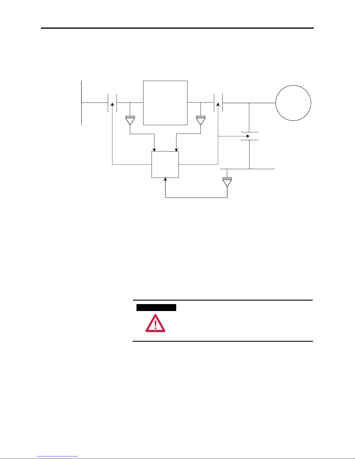
In order to perform a synchronous transfer, a drive output contactor
and a bypass contactor are required as shown in Figure 1.11. The
name bypass indicates that the function of this contactor is to connect
the motor directly to the fixed frequency supply, bypassing the drive.
An additional Voltage Sensing Board (VSB) is used to measure the
bypass voltage on the line side of the bypass contactor. These inputs
are brought in through ACB and used in synchronizing the motor
voltage directly to the bypass voltage resulting in a reliable
synchronous transfer. In addition the measurement of by pass voltage
allows certain protection features to be built in. The synchronous
transfer is automatically aborted if the drive detects an overvoltage or
undervoltage or reverse sequence in the bypass voltage.
7000-TD002A-EN-P – September 2007
Page 34
1-30 Functional Description
Synchronous Transfer
(cont.)
Inputcontactor Outputcontactor
Input bus
PF7000
PF7000
PF7000
PF7000
CONTROL
CONTROL
Bypassbus
Bypass contactor
MOTOR
MOTOR
Figure 1.11 – A typical synchronous transfer set up using PF7000
For single motor applications, the drive is capable of performing
synchronous transfer without the need for a Programmable Logic
Controller (PLC). The command to close the bypass and output
contactor and their status are realized using the digital IO on ACB.
The run time commands Request to Bypass (Synch) and Transfer to
drive (De-synch) are wired to the standard XIO board. Synchronous
transfer will not be performed if the phase sequence of the bypass
voltage is not positive.
A T T E N T I O NA T T E N T I O N
If the phase rotation and phase angle of the
bypass voltage compared to the drive input
voltage are not correct, damage may occur to the
drive, motor, couplings and driven equipment if a
transfer to bypass is attempted.
7000-TD002A-EN-P – September 2007
Page 35
Functional Description 1-31
For all multiple motor synchronizing applications, a PLC is used for
overall control of the synchronous transfer operation. Typically, the
PLC gives control of the bypass contactor to the drive before
performing the transfer, and takes back control after the transfer is
completed.
A T T E N T I O NA T T E N T I O N
Since the programmable controller and not the
drive controls the output and bypass contactors,
the transfer command must always go via the
PLC and never directly to the drive from another
controlling device (e.g. a Remote I/O adapter).
The following section will describe the sequence of operation on
single motor synchronous transfer without using a PLC.
Transfer to Bypass
When the motor is running on the drive and a synchronous transfer is
required, the transfer takes place in the following sequence:
1. The drive is given a Request to Bypass command, which must
remain active until the synchronous transfer is complete. If the
transfer command is removed before the bypass contactor is
requested to close, the drive will abort the transfer and return to
normal running. When the drive receives the transfer command,
it accelerates the motor up to the measured Bypass Frequency
(159). If the drive is unable to achieve synchronous speed, it
may be necessary to increase parameter Trq Lmt Motoring (84).
2. When the motor reaches sy nchronous speed, the synchronizing
regulator is activated whose response is controlled by parameter
Sync Reg Gain (225). It adjusts the drive Speed Reference as
required, to synchronize the motor to the bypass with the motor
voltage leading the bypass voltage by an angle specified by
parameter Sync Lead Angle (226). This parameter is used to
compensate for the drifts in the motor and bypass voltage before
the bypass contactor closes. If the phase error tends to oscillate,
it may be necessary to adjust parameters Sync Reg Gain or
Spdreg Bandwidth.
7000-TD002A-EN-P – September 2007
Page 36
1-32 Functional Description
(
)
Synchronous Transfer
cont.
3. When the phase error between the motor voltage and bypass
voltage has remained less than the value specified by parameter
Sync Error Max (228) for the time interval specified by
parameter Sync Time (229) the drive activates BP CONTACTOR
output on the ACB.
4. After a time delay specified by Sync Off Delay (227) the drive
shuts off. It is important that this parameter is set to the correct
value. This should be at least 1-2 cycles less than the contactor
closing time. If this time delay is set too short, the motor voltage
could drift out of phase with the bypass voltage. If the time delay
is set too long, a drive overcurrent fault may occur because the
drive is unable to control its output voltage and frequency once
the bypass contactor has closed.
A T T E N T I O NA T T E N T I O N
If parameter Sync Off Delay is set incorrectly,
damage may occur to the drive, motor,
couplings, and driven load if a transfer to
bypass is attempted.
5. When the BP CONTACTOR STATUS input indicates that the
bypass contactor has closed, the drive deactivates the OP
CONTACTOR output. When the output contactor opens, the
drive is disconnected from the motor, leaving the output filter
capacitors charged to bypass voltage.
6. The synchronous transfer is now complete and the motor is
running on bypass.
7. If in (3), the drive is unable to synchronize within the time
specified by parameter Sync Xfer Time (230) the synchronous
transfer is aborted. At this point the drive can either fault or issue
a warning. This is controlled by the parameter Drive Fault4
(370). If the bit SyncXferFail is set to 1, then the drive issues a
fault. If the bit is set to 0, then a warning is issued.
7000-TD002A-EN-P – September 2007
Page 37
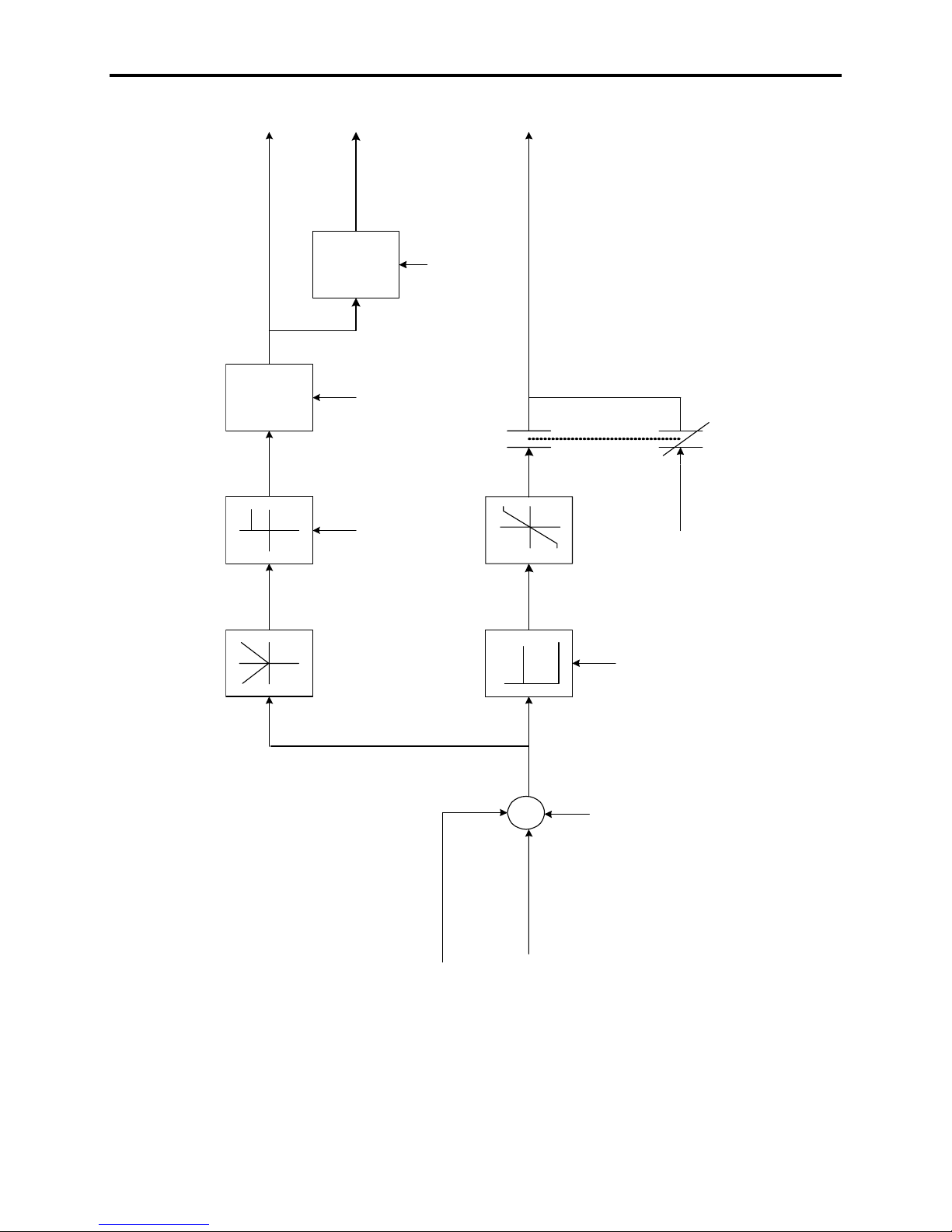
Functional Description 1-33
Close Bypass Contactor
TIME
Shut of f driveTIME
DELAY
DELAY
(229)
SyncTime
(228)
Sync Error max
(227)
Sync Off Delay
To Speed Control
(298)
Sync Reg O utput
SyncXfer Enab = 1
Enab = 0
SyncXfer
3Hz
-3 H z
Special Feature (99)
0
(225)
SYNC XFER
REGULATOR
(297)
Sync Reg Error
+
Bypass voltage angle
+
_
Motor voltage angl e
Sync Reg G ai n
(226)
Sync LeadAngle
Figure 1.12 – Transfer to Bypass
7000-TD002A-EN-P – September 2007
Page 38

1-34 Functional Description
(
)
Synchronous Transfer
Transfer to Drive
cont.
To transfer a motor running on the bypass back to the drive a
Transfer to Drive command is requested. Following sequence of
events take place:
1. The drive is given a Transfer to Drive command. After a normal
start command is given, the drive closes the output contactor.
After the OP CONTACTOR STATUS input on the ACB indicates
that the output contactor has closed, there is a time delay to
allow the output filter capacitors to charge to the bypass voltage.
This delay is adjustable using DeSync Start Dly (#763). Within
this time, the drive synchronizes to the capacitor voltage with the
motor still running on bypass. The drive then deactivates its
BP_CONTACTOR output.
2. When the BP CONTACTOR STATUS input on the ACB
indicates that the bypass contactor has opened, the drive goes to
run mode. As the drive brings the motor torque up to the level
requir ed by the load, the motor speed will drop slightly before
returning to the commanded speed.
3. The Transfer to Drive command is removed. The transfer is now
complete and the motor is running on the drive.
7000-TD002A-EN-P – September 2007
Page 39

Functional Description 1-35
+
Δ
PID Process Control The PID process control feature is now integrated into the PowerFlex
7000 drive. The PID controller provides a single closed loop process
control with proportional, integral and derivative control action. This
feature is designed to eliminate the need for external control devices
in applications that require control of a process.
The drive reads the Process Variable (357) from the analog input
that is fed by the customer process sensor and compares it to the
desired Process Setpoint (360). The analog I/O is either in the
voltage range of 0 -10V or in the current range of 4 – 20 mA. The
algorithm will then adjust the PID Output (356), changing the drive’s
speed command frequency to make the Process Variable equal to the
Process Setpoint. The internal PID process controller uses the
velocity form algorithm of the PID equation. This signifies that the
loop works on the change in error to adjust the output whereas a
traditional positional form algorithm works on the error directly.
The firmware provides several options as to the way the algorithm
works. Independent or dependent gain form can be chosen by the
Indpndt Gain bit in the PID Output (356). The difference should be
taken into consideration when tuning the PID parameters; PID Gain
(353), PID Integral Time (354) and PID Derivative Time (355). The
equations for the algorithms in dependent and independent gain form
are shown below:
Dependent Gain Form:
In this form of algorithm, the PID gain is working as a controller
gain. The change in the PID Gain will affect all three terms;
proportional, integral, and derivative.
−
1
Independent Gain Form
⎛
⎜
Pnn
⎜
⎝
1
EKPOPO
T
l
TtE
+Δ+Δ+=
d
2
EEE
+−
t
Δ
In this form of algorithm, the PID gain is working as a proportional
gain. The change in the PID Gain will affect only the proportional
term.
−
1
EKPOPO
Pnn
−211
T
+Δ+Δ+=
TtE
l
d
2
t
Δ
where: PO: PID Output
E: Error (Process Setpoint - Process Variable)
K
T
T
t
: Sampling Period used by the loop
: PID Gain
p
: PID Integral Time in seconds
l
: PID Derivative Time in seconds
d
Contact factory for the availability of this feature.
⎞
−−
nnn
21
⎟
⎟
⎠
EEE
nnn
−−
7000-TD002A-EN-P – September 2007
Page 40

1-36 Functional Description
+
−
The derivative term will act on the Process Variable instead of the
PID Process Control
(cont.)
where: PV: Process Variable
The PID controller PID Output can be selected manually from the
The control direction of the Process Variable can be changed by the
Figure 1.13 shows an overall control block diagram.
error by setting the DerivProcess bit in the PID Output to 1. In this
case, the derivative term in the above equation is replaced as below:
−=
TTermDerivative
d
2
Δ
PVPVPV
nnn
−− 21
t
PID Manual Input (348) when the Manual bit in the PID Output is
set to 1. When the Manual bit is set and the PID Manual input is still
at the default value of 0, the PID Output will be latched to the last
value from the PID controller and waits for the valid value to be
entered.
Direct bit in the PID Manual input. When this bit is set to 1 the PID
controller works in direct action, meaning that the PID Output
increases when the Process Variable is larger than the Process
Setpoint. In reverse action with the Direct bit off, the PID Output
increases when the Process Variable is smaller than the Process
Setpoint.
Contact factory for the availability of this feature.
7000-TD002A-EN-P – September 2007
Page 41
Functional Description 1-37
DriveControl
Process
Speed
PID (59)
Command
Output
Limiter
PID Minimum Limit (336)
PIDMaximumLimit (318)
Sensor
(356)
PID Output
Input (348)
PID Manual
Process
PID Controller
PID Gain (353)
PID Int egralTime (354)
PID Derivative Time (355)
PIDCommand (313)
PID Dead Bandwidth (352)
PID Preload (365)
(390)
PID Filter
LP
Filter
-
Process
Setpoint (360)
Analog I/O
ProcessGain (398)
ProcessVariable (357)
ProcessVariableEng (366)
Figure 1.13 – Process PID controller
7000-TD002A-EN-P – September 2007
Page 42
1-38 Functional Description
Power Factor Compensation This feature is available in drives with PWM rectifier to compensate
leading power factor at low motor speeds with a fan/pump type load.
Leading or lagging power factor at high motor speeds (or even above
base speed) can also be compensated or improved. The control of
power factor is realized by either controlling the modulation index of
the inverter using Space Vector Modulation (SVM) gating technique
or by adjusting the motor flux profile.
Contact factory for the availability of this feature.
Analog Outputs A total of seventeen programmable analog outputs are provided on
various boards. They are classified as customer use or diagnostic use.
See tables below. There are eight analog outputs on DPM which are
intended for diagnostic purposes and are available as test points for
connection to an oscilloscope or chart recorder. These analog outputs
are 8-bit, non-isolated, with a range of -10V to +10V. The ACB also
has one isolated 4-20mA analog output and 8 non-isolated analog
outputs for connection to external devices such as meters or isolation
modules. The allocation of the analog outputs is shown below:
Table 1.D – Analog Outputs Customer Use
No. Output Board Description
1 Meter1 ACB Connector J10
2 Meter2 ACB Connector J10
3 Meter3 ACB Connector J10
4 Meter4 ACB Connector J10
5 Output1 ACB Connector J8
6 Output2 ACB Connector J8
7 Output3 ACB Connector J8
8 Output4 ACB Connector J8
9 4-20mAOut ACB Connector J8
Table 1.E – Analog Outputs Diagnostic Use
Output Board Description
1 RecTstPt1 DPM RTP1
2 RecTstPt2 DPM RTP2
3 RecTstPt3 DPM RTP3
4 RecTstPt4 DPM RTP4
5 InvTstPt1 DPM ITP1
6 InvTstPt2 DPM ITP2
7 InvTstPt3 DPM ITP3
8 InvTstPt4 DPM ITP4
Any parameter or variable can be assigned to any analog output.
Only the outputs for customer use can be scaled by using the
corresponding scaling factor.
7000-TD002A-EN-P – September 2007
Page 43

Functional Description 1-39
Analog Inputs A total of 3 analog inputs are provided in the drive for customer use.
Typically these inputs are used for speed command and can be
configured to be either 4-20mA or 0-10V inputs. Analog Input 1 and
Analog Input 2 are used for directly controlling the speed of the
motor (Refer to section on Speed Command) while Analog Input 3 is
used for sensing the process output for the built in PID controller.
7000-TD002A-EN-P – September 2007
Page 44

1-40 Functional Description
7000-TD002A-EN-P – September 2007
Page 45
Chapter 2
Parameters
PowerFlex 7000/7000L Medium Voltage AC Drive
DATABASE REVISION # 7.xxx
This document provides detailed description of the parameters used in drive control. The parameters are
arranged into functional groups. Each description begins with the full name of the parameter, followed by
the name displayed on the operator interface. The linear number of the parameter is given followed by
the minimum and maximum values showing the position of the decimal point and the units if applicable.
Next is the generic value that is assigned when a parameter initialization is performed. The access level
at which the parameter can be first seen is given. The access levels are Monitor, Basic, Advanced,
Service and Rockwell. At the Monitor access level, no change to the parameters are allowed. If the
parameter is first seen at a certain level (with the exception of Monitor) and it is a Read/Write type, it can
be modified at the same or a higher level. Read Only parameters are operational variables that change
with different operating conditions. Finally, there is a short functional description of the parameter.
IMPORTANT: Please read the following information on overall
parameter configuration.
Interpreting Bit-Encoded Parameters
Most bit-encoded parameters follow a basic format. A one (1) in an associated bit represents a true or
active condition. A zero (0) in an associated bit represents a false or inactive condition.
The methodology is best illustrated using an example:
Hardware Options 1 [HardwareOptions1]
Linear Number: 141
Default Value: 128
Minimum Value: 0
Maximum Value: 65535
Access Level: Service
Read/Write: Read/Write when Stopped
This parameter allows user to select additional hardware options.
7000-TD002A-EN-P – September 2007
Page 46
2-2 Parameter Descriptions
Bit Enum Text Description
0 Redn ConvFan Redundant Converter Fan for Air cooled drives
1 RednIsoTxFan Redundant Isolation Tranformer Fan
2 Redn PwrSup Redundant Power Supply
3 Output IsoTx Output Isolation Transformer
4 Input IsoSw Input Isolation Switch
5 Output IsoSw Output Isolation Switch
6 Bypass IsoSw Bypass Isolation Switch
7 DCNeutralVSB Voltage Sensing Board for DC/Neutral voltage measurement
8 Output Ctctr Output Contactor installed in the drive
9 Bypass Ctctr Bypass Contactor installed in the drive
10 Ambient Temp Ambient temperature enabled
11 Rec ChB Temp Rectifier Channel B temperature
12 Redn Dvc Inv Redundant Inverter Device
13 Redn Dvc Rec Redundant Rectifier Device
14 Rockwell UPS Rockwell specified UPS installed in the drive
15 Customer UPS Customer supplied UPS installed in the drive
The description in the manual will always be structured in the same way. The top description (in this
case, Redn ConvFan) is always the least-significant bit, or right-most bit. As you move down the list of
descriptions, you move to the left on the bit-encoded word. Any unused bits in the middle of a word will
be identified, but unused bits in the middle of a word will have no description. This is why a 16-bit word
may only have a few descriptions. The rest are reserved for future expansion.
When a bit-encoded parameter is viewed in its associated group, it is actually displayed as a hexadecimal
number. The right-most four bits represent the right-most hexadecimal digit. Each subsequent group of
4 represents the next hex digit.
The following table illustrates the relationship:
Bit 15 14 13 12 11 10 9 8 7 6 5 4 3 2 1 0
Value
Example
8 4 2 1 8 4 2 1 8 4 2 1 8 4 2 1
0 1 0 1 1 1 1 0 1 0 1 1 0 0 1 1
0 + 4 + 0 + 1 8 + 4 + 2 + 0 8 + 0 + 2 + 1 0 + 0 + 2 + 1
Sums
5 E B 3
When you display a specific bit-encoded parameter, or choose to modify a bit-encoded parameter, it will
be displayed in fit format, with an individual description of each bit. When modifying a parameter,
highlighting the bit with the cursor keys will automatically pop up the description on screen.
Conversion Table
Binary Hex Binary Hex Binary Hex Binary Hex
0000 0 0100 4 1000 8 1100 C
0001 1 0101 5 1001 9 1101 D
0010 2 0110 6 1010 A 1110 E
0011 3 0111 7 1011 B 1111 F
7000-TD002A-EN-P – September 2007
Page 47

Parameter Descriptions 2-3
Feedback Parameters
Line Voltage pu [Line Voltage pu]
Linear Number: 135
Minimum Value: 0.000 pu
Maximum Value: 2.000 pu
Access Level: Service
Read/Write: Read Only
This parameter is the estimated value of the input line voltage in per unit. This is calculated from the
measured rectifier input voltage Rect Input Volt (696) and adding the voltage drop in the input impedance
due to the measured line current Line Current pu (122). The Input Impedance (140) is determined by
auto-tuning. For 18-pulse drives, the line voltage is the summation of the estimated voltage from each of
the three bridge voltages.
Rectifier Input Volt [Rec Input Volt]
Linear Number: 696
Minimum Value: 0.000 pu
Maximum Value: 2.000 pu
Access Level: Service
Read/Write: Read Only
This parameter is the measured voltage at the input of the master rectifier bridge in per unit using the
Voltage Sensing Board. For 6-PWM drive this is also the voltage across the line filter capacitor. For 18pulse drives this value represents the voltage at the input of the master bridge and will be approximately
one third of the Line Voltage pu (135). This parameter is used for protection and also by the flux controller
to adjust the flux command during input voltage sag conditions.
Rectifier DCLink Volt [Rec DCLink Volt]
Linear Number: 645
Minimum Value: -2.000 pu
Maximum Value: 2.000 pu
Access Level: Service
Read/Write: Read Only
This parameter displays the measured DC Link voltage in per unit on the rectifier side using the Voltage
Sensing Board.
Inverter DCLink Volt [Inv DCLink Volt]
Linear Number: 643
Minimum Value: -2.000 pu
Maximum Value: 2.000 pu
Access Level: Service
Read/Write: Read Only
This parameter displays the measured DC Link voltage on the inverter side in per unit using the Voltage
Sensing Board.
7000-TD002A-EN-P – September 2007
Page 48

2-4 Parameter Descriptions
Inverter Output Volt [Inv Output Volt]
Linear Number: 761
Minimum Value: 0.000 pu
Maximum Value: 2.000 pu
Access Level: Service
Read/Write: Read Only
This parameter is the measured inverter output voltage in per unit using the Voltage Sensing Board
(VSB). This is the voltage across the motor filter capacitor. For non-ESP applications, the motor voltage
will be equal to the inverter output voltage. However for ESP applications, the inverter output voltage will
be higher than the motor voltage to compensate the voltage drop in the cable. A new parameter Surface
Voltage (#760) displays the inverter output voltage in Volts.
Motor Voltage pu [Motor Voltage pu]
Linear Number: 554
Minimum Value: 0.000 pu
Maximum Value: 2.000 pu
Access Level: Service
Read/Write: Read Only
This parameter displays the voltage across the motor terminals in per unit. For non-ESP applications, the
motor voltage will be equal to the inverter output voltage. However for ESP applications the motor voltage
is estimated from the measured output voltage Inv Output Volt (761) and compensating for the cable
resistance drop using measured motor current Motor Current pu (555).
Line Current pu [Line Current pu]
Linear Number: 122
Minimum Value: 0.000 pu
Maximum Value: 4.000 pu
Access Level: Service
Read/Write: Read Only
This parameter displays the measured value of line current in per-unit. It is measured using Current
Transformers (CT’s) installed in two phases. The drive internally reconstructs the line current in the third
phase by assuming that the sum of the line currents in a three phase system is zero. The line current is
the sum of the current flowing into the rectifier bridge and the current flowing into the line filter capacitor.
Motor Current pu [Motor Current pu]
Linear Number: 555
Minimum Value: 0.000 pu
Maximum Value: 4.000 pu
Access Level: Service
Read/Write: Read Only
This parameter displays the measured value of motor current in per-unit. It is measured using Hall Effect
Current Sensors (HECS) installed in two phases. The drive internally reconstructs the motor current in the
third phase by assuming that the sum of the motor currents in a three phase system is zero.
Rectifier Heat Sink Temp °C [Rec HSink Temp C]
Linear Number: 254
Minimum Value: -40.0 C
Maximum Value: 100.0 C
Access Level: Monitor
Read/Write: Read Only
This parameter specifies the rectifier heat sink temperature in degrees Celsius.
7000-TD002A-EN-P – September 2007
Page 49

Parameter Descriptions 2-5
Rectifier Heat Sink Temp °F [Rec HSink Temp F]
Linear Number: 255
Minimum Value: -40.0 F
Maximum Value: 212.0 F
Access Level: Monitor
Read/Write: Read Only
This parameter specifies the rectifier heat sink temperature in degrees Fahrenheit.
Inverter Heat Sink Temp °C [Inv HSink Temp C]
Linear Number: 252
Minimum Value: -40.0 C
Maximum Value: 100.0 C
Access Level: Monitor
Read/Write: Read Only
This parameter specifies the inverter heat sink temperature in degrees Celsius.
Inverter Heat Sink Temp °F [Inv HSink Temp F]
Linear Number: 253
Minimum Value: -40.0 F
Maximum Value: 212.0 F
Access Level: Monitor
Read/Write: Read Only
This parameter specifies the inverter heat sink temperature in degrees Fahrenheit.
Air Filter Blockage [Air Filter Block]
Linear Number: 567
Minimum Value: 0.0 %
Maximum Value: 100.0 %
Access Level: Basic
Read/Write: Read Only
This parameter specifies the amount of air filter blockage in %. An increasing value is an indication of air
filter blocking. The blockage is calculated from the measured Convrter AirFlow (447) and the nominal
converter air flow Conv AirFlow Nom (417). A drop in pressure sensor value is an indication of reduced
airflow in the drive due to a blocked air filter. The drive continuously monitors this value and will trip
before the air filter gets fully blocked.
Air Filter Allow [Air Filter Allow]
Linear Number: 568
Minimum Value: 0.0 %
Maximum Value: 100.0 %
Access Level: Basic
Read/Write: Read Only
This parameter specifies the % allowable filter blockage before the drive will trip. A decreasing value is an
indication of air filter blocking.
7000-TD002A-EN-P – September 2007
Page 50

2-6 Parameter Descriptions
Converter Air Flow [Convrter AirFlow]
Linear Number: 447
Minimum Value: -1.0 V
Maximum Value: 10.0 V
Access Level: Basic
Read/Write: Read Only
This parameter displays the output of the air pressure sensor in volts. It is an indication of the airflow in
the drive. A drop in pressure value indicates either a blocked air filter or a loss of cooling fan operation.
This parameter along with Conv Airflow Nom (317), Conv AirFlow Trp (319) and Conv AirFlow Wrn (320)
are used for protection.
Integral Isolation Transformer Air Flow [IsoTx AirFlow]
Linear Number: 653
Minimum Value: -10.0 V
Maximum Value: 10.0 V
Access Level: Basic
Read/Write: Read Only
This parameter displays the output of the air pressure sensor in volts installed in the Isolation
Transformer section of the A-Frame drive. This parameter operates with the same functionality as the
converter air flow pressure i.e. a decreasing value is an indication of blocked filters. This parameter
along with IsoTx AirflowNom (656), IsoTx AirFlowTrp (654) and IsoTx AirFlowWrn (655) are used for
protection. THIS PARAMETER IS ACTIVE FOR A-FRAME DRIVES ONLY.
Line Neutral Voltage [LineNeutral Volt]
Linear Number: 589
Minimum Value: -2.000 pu
Maximum Value: 2.000 pu
Access Level: Basic
Read/Write: Read Only
This parameter specifies the measured line side neutral to ground voltage in per unit. For PWM rectifier
drives, the drive uses the measured voltage of the line capacitor neutral. For SCR drives the drive
calculates the neutral voltage by summing the line to ground voltages from the master bridge (zerosequence).
Motor Neutral Voltage [Mtr Neutral Volt]
Linear Number: 347
Minimum Value: -2.000 pu
Maximum Value: 2.000 pu
Access Level: Basic
Read/Write: Read Only
This parameter specifies the measured motor neutral to ground voltage in per unit. The drive calculates
the neutral voltage by summing the line to ground motor voltages (zero-sequence).
Refer the following table for typical values of neutral voltages in the drive.
Rectifier type Line Neutral Voltage Motor Neutral Voltage
18 pulse > 0.3pu < 0.1pu (with grounding network)
6PWM(grounded system) < 0.1pu > 0.3pu
6PWM(floating system) > 0.3pu < 0.1pu (with grounding network)
6PWM(Direct-to-Drive) < 0.1pu < 0.1pu
7000-TD002A-EN-P – September 2007
Page 51

Parameter Descriptions 2-7
Master Bridge Line Voltage [Master Line Volt]
Linear Number: 136
Minimum Value: 0.000 pu
Maximum Value: 2.000 pu
Access Level: Service
Read/Write: Read Only
This parameter is the estimated value of the master bridge input voltage in per unit. This is calculated
from the measured rectifier input voltage and adding the voltage drop in the input impedance due to the
measured line current Master Line Cur (382). The Input Impedance (140) is determined by auto-tuning.
Slave 1 Bridge Line Voltage [Slave1 Line Volt]
Linear Number: 137
Minimum Value: 0.000 pu
Maximum Value: 2.000 pu
Access Level: Service
Read/Write: Read Only
This parameter is the estimated value of the slave 1 bridge input voltage in per unit. This parameter is
valid for 18 SCR drives only. This is calculated from the measured slave1 bridge voltage and adding the
voltage drop in the input impedance due to the measured line current Slave1 Line Cur (383). The Input
Impedance (140) is determined by auto-tuning.
Slave 2 Bridge Line Voltage [Slave2 Line Volt]
Linear Number: 138
Minimum Value: 0.000 pu
Maximum Value: 2.000 pu
Access Level: Service
Read/Write: Read Only
This parameter is the estimated value of the slave 2 bridge input voltage in per unit. This parameter is
valid for 18 SCR drives only. This is calculated from the measured slave2 bridge voltage and adding the
voltage drop in the input impedance due to the measured line current Slave2 Line Cur (384). The Input
Impedance (140) is determined by auto-tuning.
Master Bridge Line Current [Master Line Cur]
Linear Number: 382
Minimum Value: 0.000 pu
Maximum Value: 4.000 pu
Access Level: Service
Read/Write: Read Only
This parameter specifies the measured master bridge input current.
Slave 1 Bridge Line Current [Slave1 Line Cur]
Linear Number: 383
Minimum Value: 0.000 pu
Maximum Value: 4.000 pu
Access Level: Service
Read/Write: Read Only
This parameter specifies the measured slave1 bridge input current in per unit for 18-pulse drives.
7000-TD002A-EN-P – September 2007
Page 52

2-8 Parameter Descriptions
Slave 2 Bridge Line Current [Slave2 Line Cur]
Linear Number: 384
Minimum Value: 0.000 pu
Maximum Value: 4.000 pu
Access Level: Service
Read/Write: Read Only
This parameter specifies the measured slave2 bridge input current in per unit for 18-pulse drives.
Master Bridge Line Frequency [Master Line Freq]
Linear Number: 334
Minimum Value: -100.0 Hz
Maximum Value: 100.0 Hz
Access Level: Service
Read/Write: Read Only
This parameter specifies the instantaneous frequency of the voltage on the Master rectifier bridge. The
sign of the frequency is negative for reverse phase sequence on that bridge.
Slave 1 Bridge Line Frequency [Slave1 Line Freq]
Linear Number: 335
Minimum Value: -100.0 Hz
Maximum Value: 100.0 Hz
Access Level: Service
Read/Write: Read Only
This parameter specifies the instantaneous frequency of the voltage on the Slave 1 bridge for 18-pulse
drives. The sign of the frequency is negative for reverse phase sequence on that bridge.
Slave 2 Bridge Line Frequency [Slave2 Line Freq]
Linear Number: 239
Minimum Value: -100.0 Hz
Maximum Value: 100.0 Hz
Access Level: Service
Read/Write: Read Only
This parameter specifies the instantaneous frequency of the voltage on the Slave 2 bridge for 18-pulse
drives. The sign of the frequency is negative for reverse phase sequence on that bridge.
Slave1 Bridge Phase Angle [Slave1 Angle]
Linear Number: 616
Minimum Value: -360.0 deg
Maximum Value: 360.0 deg
Access Level: Service
Read/Write: Read Only
This parameter is the measured phase angle between the Master and the Slave 1 bridges and is
applicable for 18 SCR drives only. It should be close to –20 deg.
7000-TD002A-EN-P – September 2007
Page 53

Parameter Descriptions 2-9
Slave2 Bridge Phase Angle [Slave2 Angle]
Linear Number: 617
Minimum Value: -360.0 deg
Maximum Value: 360.0 deg
Access Level: Service
Read/Write: Read Only
This parameter is the measured phase angle between the Master and the Slave 2 bridges and is
applicable for 18 SCR drives only. It should be close to +20 deg.
Harmonic Voltage [Harmonic Voltage]
Linear Number: 683
Minimum Value: 0.000 pu
Maximum Value: 32.767 pu
Access Level: Service
Read/Write: Read Only
This parameter represents the calculated value of the Harmonic Voltage on the input to the rectifier. The
firmware looks at the rectifier voltage and will measure the 5
th
harmonic voltage only. This value is
normalized to the rated line voltage, and will trip when the harmonic voltage exceeds the setting in the
parameter Harmonic VoltTrp (675) for the time specified in Harmonic VoltDly (676).
Common Mode Peak Current [ComModeCur Peak]
Linear Number: 779
Minimum Value: 0.00 A
Maximum Value: 655.35 A
Access Level: Service
Read/Write: Read Only
This parameter is for Direct-to-Drives only and displays the peak value of common mode current flowing
in the neutral resistor.
Peak Transient Volt [TransientVoltMax]
Linear Number: 778
Minimum Value: 0.000 pu
Maximum Value: 2.000 pu
Access Level: Service
Read/Write: Read Only
The peak capacitor voltage during the last bus transient is saved in the variable Peak Tran Volt #778.
Bus Transient Trip [BusTransient Trp]
Linear Number: 684
Minimum Value: 0.000 pu
Maximum Value: 32.767 pu
Access Level: Service
Read/Write: Read Only
This parameter shows the internal Bus Transient Trip value.
7000-TD002A-EN-P – September 2007
Page 54
2-10 Parameter Descriptions
Bus Transient Level [BusTransient Lvl]
Linear Number: 767
Minimum Value: 0.000 pu
Maximum Value: 32.767 pu
Access Level: Service
Read/Write: Read Only
The bus transient algorithm has been improved to reduce self-induced nuisance trips caused by fast dc
current, pulse number and firing angle changes. The rectifier temporarily disables the bus transient when
it determines that it may generate a transient in the input filter. This can be compared to Bus Tran Trip
#684 to determine when the transient occurs.
Diagnostics Parameters
Logic Command [Logic Command]
Linear Number: 257
Access Level: Monitor
Read/Write: Read Only
This parameter specifies the logic command used by the drive control. Refer to Appendix A for detailed
implementation. The following commands are displayed, with a one representing an active command:
Bit Enum Text Description
0 Not Stop Drive is ready to Run
1 Start Start the Drive
2 Jog Start the drive in Jog mode
3 Clr Flt Que Clear the Fault queue
4 Clr Warn Que Clear the Warning queue
5 Drive Reset Reset the drive
6 Direction Direction of rotation
7 Start Profle Drive Start profile
8 Stop Profle Drive Stop profile
9 Flash Mode DPI Adapter in Flash Mode
10 Unused
11 Synch Synchronous transfer to Bypass from Drive
12 De-Synch Synchronous transfer to Drive from Bypass
13 Force Stop Force Stop the drive (DPI)
14 Force Fault Force Fault the drive (DPI)
15 Unused
7000-TD002A-EN-P – September 2007
Page 55
Parameter Descriptions 2-11
Logic Status [Logic Status]
Linear Number: 258
Access Level: Monitor
Read/Write: Read Only
This parameter specifies the value of logic status. A one represents an active condition, and it is bit
encoded as follows:
Bit Enum Text Description
0 Ready The drive is in Ready condition.
1 Running The drive is Running.
2 Command Dir Commanded direction of rotation, 1 is Forward 0 is Reverse (check)
3 Rotation Dir Actual Direction of rotation 1 is Forward 0 is Reverse (check)
4 Accelerating The drive is accelerating.
5 Decelerating The drive is decelerating.
6 At Speed The drive has reached commanded speed.
7 On Bypass The drive is currently running on bypass.
8 Rev Enabled Reverse r o t a t i on o f t h e d ri v e h a s been enabled (Refer Special Features)
9 Drive Fault Drive is in Fault mode
10 Drive Warn Drive is in Warning mode
11 Local Lock An adaptor has local control of the drive
12 Forced Stop DPI adapter has issued a forced stop command
13 Speed Com1 Speed reference source
14 Speed Com2 Speed reference source
15 Speed Com3 Speed reference source
Drive Not Ready Status Word 1 [Drive Not Ready1]
Linear Number: 262
Access Level: Monitor
Read/Write: Read Only
This parameter specifies the status of several different conditions that can cause a Drive Not Ready
indication. ‘1’ in the corresponding bit location indicates that condition exists, and ‘0’ indicates that the
condition does not exist. The following is description of the individual bits:
Bit Enum Text Description
0 Class1 Fault A Class 1 Fault Exists
1 Class2 Fault A Class 2 Fault Exists
2 No Line Sync The drive failed to synchronize with the incoming line voltage
3 No Phase Chk Phasing Check on the Rectifier has not passed
4 Inp Clse Dly The drive is waiting for the line filter capacitor to discharge.
5 Inp IsoOpen The Drive Input Isolation Switch is Open when it should not be
6 Out IsoOpen The Drive Output Isolation Switch is Open when it should not be
7 Byp IsoOpen The Drive Bypass Isolation Switch is Open when it should not be
8 No Out Ctctr In Open Circuit Mode, the drive will not start if the drive does not have
an Output contactor installed.
9 Inp IsoClsd The Drive Input Isolation Switch is Closed when it should not be
10 Out IsoClsd The Drive Output Isolation Switch is Closed when it should not be
11 Byp IsoClsd The Drive Bypass Isolation Switch is Closed when it should not be
12 DPI Flash The DPI Adapter is being flashed remotely
13 Drv Xfer Dly The drive is waiting for the motor filter capacitor to discharge after a
successful synchronization and will not allow de-sync
14 Line Loss Loss of Medium Voltage
15 CtrlPwr Loss Loss of Control Power
7000-TD002A-EN-P – September 2007
Page 56
2-12 Parameter Descriptions
Drive Not Ready Status Word 2 [Drive Not Ready2]
Linear Number: 699
Access Level: Monitor
Read/Write: Read Only
This parameter specifies the status of several different conditions that can cause a Drive Not Ready
indication. ‘1’ in the corresponding bit location indicates that condition exists, and ‘0’ indicates that the
condition does not exist. The following is description of the individual bits:
Bit Enum Text Description
0 SCR Gate Pwr The self powered gate drive boards for SCR drives are not charged
1 InpCtctrOpen The Drive Input Contactor is Open when it should not be
2 Unused
3 Unused
4 Unused
5 Unused
6 Unused
7 Unused
8 Unused
9 Unused
10 Unused
11 Unused
12 Unused
13 Unused
14 Unused
15 Unused
Drive Status Flags 1 [DrvStatus Flag1]
Linear Number: 569
Access Level: Service
Read/Write: Read Only
This parameter specifies the drive status flags. Each bit has 2 states, and that allows the parameter to
represent 16 conditions. They are as shown below:
Bit 0 – Enum Text 1 – Enum Text
0 Not Ready Ready
1 Not Running Running
2 Forward Rotation Reverse Rotation
3 No Faults Faulted
4 No Warnings Warnings
5 Fans Off Fans On
6 Input Open Input Closed
7 Output Open Output Closed
7000-TD002A-EN-P – September 2007
Page 57
Parameter Descriptions 2-13
Drive Status Flag 2 [DrvStatus Flag2]
Linear Number: 238
Access Level: Service
Read/Write: Read Only
This parameter specifies the drive status flag and is used by drive control to make logical decisions. A ‘1’
represents an indicated status. The following states are displayed:
Bit Enum Text Description
0 Jog Drive is in Jog mode.
1 Local Drive is in Local Control Mode.
2 Class1 Fault Drive has tripped on a Class 1 Fault.
3 Class2 Fault Drive has tripped on a Class 2 Fault.
4 Run Req Drive start command has been issued.
5 Restart Req Drive will restart automatically following a line loss.
6 Gating Enble Line and machine converter devices are gating.
7 Drive Init Drive Initialization routines have been completed.
8 Gate Test Drive is in Gate Test mode.
9 Shrt Cct Tst Drive is in DC Current Test mode.
10 System Tst Drive is in System Test mode.
11 Open Cct Tst Drive is in Open Circuit Test mode.
12 Param Loaded Drive Parameters have been loaded.
13 Inv Init Inverter side initialization routines have been completed.
14 StaFlg2Bit14 Not Used bit
15 Conv Fan2 On Opt ional redundant converter cooling fan (Fan 2) has been switched on
Contactor Command [Contactor Cmd]
Linear Number: 505
Access Level: Service
Read/Write: Read Only
This parameter displays the command to close the various contactors configured with the drive (input,
output, and bypass). The contactors are specified by the parameter Hardware Options1 (141). A ‘1’
indicates that the contactor is being commanded by the drive to close.
Bit Enum Text Description
0 Input Ctctr Close Input contactor
1 Output Ctctr Close Output contactor
2 Bypass Ctctr Close Bypass contactor
3 Not Used
4
5
6
7
Not Used
Not Used
Not Used
Not Used
7000-TD002A-EN-P – September 2007
Page 58
2-14 Parameter Descriptions
Contactor Status [Contactor Status]
Linear Number: 506
Access Level: Service
Read/Write: Read Only
This parameter displays the status of the various contactors and their isolating switches configured with
the drive. A ‘1’ indicates that the contactor or the isolating switch is closed. This parameter is used by the
drive for protection. If a contactor has been commanded to close and is determined not to be closed, then
the drive will trip. Similarly depending on the Operating Mode of the drive, if the isolating switch status is
opposite to the expected then the drive will trip.
Bit Enum Text Description
0 Input IsoSw Status of Input Isolation Switch
1 Input Ctctr Status of Input Contactor
2 Output IsoSw Status of Output Isolation Switch
3 Output Ctctr Status of Output Contactor
4 Bypass IsoSw Status of Bypass Isolation Switch
5 Bypass Ctctr Status of Bypass Contactor
6 Not Used
7 Not Used
Rectifier Control Flag 1 [RecControl Flag1]
Linear Number: 264
Access Level: Service
Read/Write: Read Only
This word indicates various status bits within the rectifier control. The word can be used in trending to
assist in determining what the rectifier control is doing in a normal or abnormal situation. A 1 in a location
indicates that condition is active, and a 0 indicates the condition is inactive.
Bit Enum Text Description
0 PLL Locked Rectifier Synchronized with the Line Voltage
1 PLL Enabled Input Voltage sufficient to attempt to lock onto the Line Voltage
2 Continuous DC link current is continuous
3 Rvs Sequence The incoming line is not UVW
4 Slave Swap The Slave 1 and Slave 2 Bridges are Swapped (18P only)
5 Phasing OK The drive has no phasing problems
6 MV Isolated There is no MV on the input to the rectifier
7 RecAnlgTstDn Rectifier Analog self tests completed
8 Rec Init Boot-Up on Rectifier is complete
9 Line Loss There is a line loss condition present
10 Slv1 RvsRotn The Slave 1 bridge is UWV (18P only)
11 Slv2 RvsRotn The Slave 2 bridge is UWV (18P only)
12 Diag Done The rectifier has completed the device diagnostics
13 Phasing Chk Phasing check is in progress
14 Gate Freeze The rectifier is in Gate Freeze Mode
15 InpStdyState The input voltage has reached steady state after a power up transient
7000-TD002A-EN-P – September 2007
Page 59
Parameter Descriptions 2-15
Rectifier Control Flags 2 [RecControl Flag2]
Linear Number: 160
Access Level: Service
Read/Write: Read Only
This word indicates various status bits within the rectifier control. The word can be used in trending to
assist in determining what the rectifier control is doing in a normal or abnormal situation. A 1 in a location
indicates that condition is active, and a 0 indicates the condition is inactive.
Bit Enum Text Description
0 RecClass1Flt A Rectifier Class 1 fault exists
1 RecClass2Flt A Rectifier Class 2 fault exists
2 Rec Warning A Rectifier Warning exists
3 PhsngChkDone The drive has completed the input phasing checks
4 No PLL Error There is no problems with the PLL Lock
5 Offline Diag The rectifier has completed the offline device diagnostics
6 FreeWhl Rec The rectifier is in Free-Wheel mode (caused by Bus Transients)
7 FreeWhl Inv The inverter is in Free-Wheel mode (caused by Bus Transients)
8 Device Short The Rectifier has detected a shorted device
9 BusTransient There is a transient detected on the input of the drive
10 FreeWhlReset Handshake for Freewheel Mode
11 RecSGCT Pwr Rectifier SGCTs have Power
12 RtdLimit Req Drive is requested to go into Retard Limit
13 InvAdvLmtReq Inverter is requested to go into Advance Limit
14 Drv OL Pend Drive Overload is Timing
15 Rec Crit Flt Rectifier has detected a Critical Fault
Rectifier Control Flags 3 [RecControl Flag3]
Linear Number: 368
Access Level: Service
Read/Write: Read Only
This word indicates various status bits within the rectifier control. The word can be used in trending to
assist in determining what the rectifier control is doing in a normal or abnormal situation. A 1 in a location
indicates that condition is active, and a 0 indicates the condition is inactive.
Bit Enum Text Description
0 No Flt Delay Internal fault timers disabled
1 Act Dschrge Active discharge
2 Lnk Dschrge DC Link Voltage Discharge
3 Lnk PDschrge DC Link Voltage Pre Discharge
4 Gate Enbl Rq Gate enable request
5 SCR Gate Pwr SCR Gate Power
6 Inp Open Req Input Open Request
7 Gnd OC Disbl Ground OC disabled
8 BusTran Enbl Bus Transient enabled
9 DvcLineShort Device Line to Line short
10 DvcCMVE Shrt Device CMVE SC
11 InpLockOut Due to Line Over Current condition, the input contactor is being
prevented from closing (18P only)
12 InpLock5min Due to Line Over Current condition, the input contactor is being
prevented from closing for 5 minutes(18P only)
13 InpLockIndef Due to Line Over Current condition, the input contactor is being
prevented from closing indefinitely (18P only).
14 Inp Dschargd Line filter capacitors have been discharged
15 RecFlg3Bit15 Unused bit
7000-TD002A-EN-P – September 2007
Page 60
2-16 Parameter Descriptions
Inverter Control Flags 1 [InvControl Flag1]
Linear Number: 265
Access Level: Service
Read/Write: Read Only
This word indicates various status bits within the inverter control. The word can be used in trending to
assist in determining what the rectifier control is doing in a normal or abnormal situation. A 1 in a location
indicates that condition is active, and a 0 indicates the condition is inactive.
Bit Enum Text Description
0 Mtr PLL Lock Inverter control is locked to the rotor flux position
1 SpdRamp Enbl Torque Ramp is complete and the speed ramp has been enabled
2 Mtr Rvs Seqn The output voltage is not UVW
3 Close Loop The drive is operating in closed-loop mode
4 FlxFbk Enbl The drive is using the measured flux feedback from the motor
5 FreqFbk Enbl The drive is using the measured stator frequency from the motor
6 Gate Freeze The inverter is in Gate Freeze mode
7 Scurve Prof The drive is running with an S-Curve Speed Profile
8 Drv Crit Flt Inverter has detected a Critical Fault
9 TrqRamp Enbl Motor Flux Time has expired and the drive is increasing the torque
reference to TrqCmd0 Snsrless or TrqCmd0 Tach
10 Coast Stop Not Currently Active
11 PID Enabled PID process control is enabled
12 TachFbk Optn The drive has a Tachometer/Encoder feedback signal available
13 TachFbk Enbl The drive is running with Tachometer/Encoder Feedback enabled
14 Torque Lmt The drive is in Torque Limit
15 InvFlg1Bit15 Unused bit
Contact factory for availability
Inverter Control Flags 2 [InvControl Flag2]
Linear Number: 642
Access Level: Service
Read/Write: Read Only
This word indicates various status bits within the inverter control. The word can be used in trending to
assist in determining what the rectifier control is doing in a normal or abnormal situation. A 1 in a location
indicates that condition is active, and a 0 indicates the condition is inactive.
Bit Enum Text Description
0 InternlStart Internal Start Command from Setup Wizard
1 InternalStop Internal Stop Command from Setup Wizard
2 AutotuneCncl Autotune has been aborted
3 Discharging The Line filters capacitors are discharging (more than 50V)
4 Dvc Short The Inverter has detected a shorted SGCT
5 CtrlPwr Loss The drive is in a Control Power Loss mode
6 AC Fail The drive has detected an AC power loss condition
7 InvAnlgTstDn Inverter Analog test is done
8 FreeWhlReset Handshake for Freewheel Mode
9 InvSGCT Pwr Inverter SGCTs have Power
10 AC Pwr Fail The drive has detected an AC power loss condition from the ACB
11 InvDiag Done The inverter diagnostics have been completed
12 InvTemp Loss The inverter temperature feedback is missing
13 VdcVnVSBInst DC and neutral voltage feedback board is installed
14 Mtr OL Pend Motor Overload is Timing
15 SpeedRampRvs Ramp reversing enabled
7000-TD002A-EN-P – September 2007
Page 61
Parameter Descriptions 2-17
Inverter Control Flags 3 [InvControl Flag3]
Linear Number: 446
Access Level: Service
Read/Write: Read Only
This word indicates various status bits within the inverter control. The word can be used in trending to
assist in determining what the rectifier control is doing in a normal or abnormal situation. A 1 in a location
indicates that condition is active, and a 0 indicates the condition is inactive.
Bit Enum Text Description
0 PF Achieved Desired power factor compensation has been achieved
1 RestartExprd AutoRestart Delay timer has expired
2 PFC Leading Leading Power factor compensation has been enabled
3 Out Dschrgd Motor filter capacitors have been discharged to 5% of rated
4 UWV Seq UWV Sequence enabled
5 IsoTx Fan1 Isolation Transformer 1 Fan is ON
6 IsoTx Fan2 Isolation Transformer 2 Fan is ON
7 ESP Drive ESP Drive selected
8 Restart Mode Auto Restart mode enabled
9 Cool Fans On Drive Cooling Fans ON
10 PFC Optimal Optimal Power factor compensation has been enabled
11 PFC Mod Ctrl Power factor compensation using modulation index control
12 Flying Strt1 Flying Start State 1
13 Flying Strt2 Flyig Start State 2
14 Flying Start Flying Start mode is active
15 PFC FlxRange Flux limit has been reached while compensating for line power factor
Inverter Analog Self Test Code 1 [InvAnlg SelfTst1]
Linear Number: 96
Access Level: Service
Read/Write: Read Only
This parameter specifies the power-up diagnostic results on the Analog Control Board. It refers to the
signals used by the inverter (Slave) processor. If the software detects a problem with the analog signals
into the board, or the board itself, an InvAnlg SelfTest fault will appear. This parameter will help indicate
which signals are causing the problem. The action should be to investigate all the connections and
feedback paths related to that signal before changing the ACB or the DPM. This is a self-test fault that
will only occur at initial power-up.
Bit Enum Text Description
0 HECSU Offset Phase U Motor Current Offset High
1 HECSW Offset Phase V Motor Current Offset High
2 UV Offset Phase UV Motor Voltage Offset High
3 VW Offset Phase VW Motor Voltage Offset High
4 VSAB Offset Bypass UV Voltage Offset High
5 VSBC Offset Bypass VW Voltage Offset High
6 2UV Offset Master Bridge Phase UV Voltage Offset High (for Synch. Transfer)
7 2VW Offset Master Bridge Phase VW Voltage Offset High (for Synch. Transfer)
8 VMDC1 Offset Motor Side DC Link Voltage Offset High
9 VMDC2 Offset Motor Side DC Link Voltage Offset High
10 UV_2 Offset Phase UV Motor Voltage Offset High (used for low motor voltage)
11 VW_2 Offset Phase VW Motor Voltage Offset High (used for low motor voltage)
12 MFCN Offset Motor Filter Capacitor Neutral Voltage Offset High
13 VZS Offset Motor Zero Sequence Voltage Offset High
14 UV_NF Offset Unfiltered Phase UV Motor Voltage Offset High
15 VW_NF Offset Unfiltered Phase VW Motor Voltage Offset High
Contact factory for availability
7000-TD002A-EN-P – September 2007
Page 62
2-18 Parameter Descriptions
Inverter Analog Self Test Code 2 [InvAnlg SelfTst2]
Linear Number: 251
Access Level: Service
Read/Write: Read Only
This parameter specifies the power-up diagnostic results on the Analog Control Board. It refers to the
signals used by the inverter processor. If the software detects a problem with the analog signals into the
board, or the board itself, an InvAnlg SelfTest fault will appear. This parameter will help indicate which
signals are causing the problem. The action should be to investigate all the connections and feedback
paths related to that signal before changing the ACB or the DPM. This is a self-test fault that will only
occur at initial power-up. Ignoring the faults can results in abnormal drive behavior.
Bit Enum Text Description
0 AC1 Offset Offset measured on AC control power #1
1 AC2 Offset Offset measured on AC control power #2
2 AC3 Offset Offset measured on AC control power #3
3 AC4 Offset Offset measured on AC control power #1
4 AP0 Offset Offset on Converter air flow Air Pressure 0 Sensor
5 AP1 Offset Offset on Isolation transformer pressure circuit.
6 AOUT_DAC Reserved for future use
7 METER_DAC Reserved for future use
8 TRIP_DAC Reserved for future use
9 Unused
10 Unused
11 Unused
12 Unused
13 Unused
14 Unused
15 Unused
Contact factory for availability
Rectifier Analog Self Test Code 1 [RecAnlg SelfTst1]
Linear Number: 473
Access Level: Service
Read/Write: Read Only
This parameter specifies the power-up diagnostic results on the Analog Control Board. It refers to the
signals used by the rectifier (Master) processor. If the software detects a problem with the analog signals
into the board, or the board itself, a RecAnlg SelfTest fault will appear. This parameter will help indicate
which signals are causing the problem. The action should be to investigate all the connections and
feedback paths related to that signal before changing the ACB or the DPM. This is a self-test fault that
will only occur at initial power-up.
Bit Enum Text Description
0 CT2U Offset Master Bridge Phase 2U Current Offset High
1 CT2W Offset Master Bridge Phase 2V Current Offset High
2 CT3U Offset Slave 1 Bridge Phase 3U Current Offset High
3 CT3W Offset Slave 1 Bridge Phase 3V Current Offset High
4 CT4U Offset Slave 2 Bridge Phase 4U Current Offset High
5 CT4W Offset Slave 2 Bridge Phase 4V Current Offset High
6 2UV Offset Master Bridge Phase UV Voltage Offset High
7 2VW Offset Master Bridge Phase VW Voltage Offset High
8 3UV Offset Slave 1 Bridge Phase UV Voltage Offset High
9 3UW Offset Slave 1 Bridge Phase VW Voltage Offset High
10 4UV Offset Slave 2 Bridge Phase UV Voltage Offset High
11 4UW Offset Slave 2 Bridge Phase VW Voltage Offset High
12 2UV_NFOffset Unfiltered Master Bridge Phase UV Voltage Offset High
13 2VW_NFOffset Unfiltered Master Bridge Phase VW Voltage Offset High
14 3UV_NFOffset Unfiltered Slave 1 Bridge Phase UV Voltage Offset High
15 3VW_NFOffset Unfiltered Slave 1 Bridge Phase VW Voltage Offset High
7000-TD002A-EN-P – September 2007
Page 63
Parameter Descriptions 2-19
Rectifier Analog Self Test Code 2 [RecAnlg SelfTst2]
Linear Number: 474
Access Level: Service
Read/Write: Read Only
This parameter specifies the power-up diagnostic results on the Analog Control Board. It refers to the
signals used by the rectifier (Master) processor. If the software detects a problem with the analog signals
into the board, or the board itself, a RecAnlg SelfTest fault will appear. This parameter will help indicate
which signals are causing the problem. The action should be to investigate all the connections and
feedback paths related to that signal before changing the ACB or the DPM. This is a self-test fault that
will only occur at initial power-up.
Bit Enum Text Description
0 HECSDC1Offst DC Link Current Offset High
1 HECSDC2Offst DC Link Current Offset High
2 LFCN1 Offset Line Filter Capacitor Neutral Voltage Offset High
3 LFCN2 Offset Line Filter Capacitor Neutral Voltage Offset High
4 VZS2 Offset Line Zero Sequence Voltage Offset High
5 VZS3 Offset Line Zero Sequence Voltage Offset High
6 VLDC1 Offset Line Side DC Link Voltage Offset High
7 VLDC2 Offset Line Side DC Link Voltage Offset High
8 IGND Offset Ground Fault Current Offset High
9 INN Offset Common Mode Choke Current Offset High
10 VNN Offset Common Mode Choke Neutral Resistor Voltage Offset High
11 VSPAREOffst Reserved for future use
12 HECSDC1_V2F Reserved for future use
13 HECSDC2_V2F Reserved for future use
14 Unused
15 Unused
Contact factory for availability
Rectifier Analog Self Test Code 3 [RecAnlg SelfTst3]
Linear Number: 494
Access Level: Service
Read/Write: Read Only
his parameter specifies the power-up diagnostic results on the Analog Control Board. It refers to the
signals used by the rectifier (Master) processor. This parameter is currently not being used and is
intended for future use.
Contact factory for availability
7000-TD002A-EN-P – September 2007
Page 64
2-20 Parameter Descriptions
Current Sensor Fault Code [Cur Sens FltCode]
Linear Number: 764
Access Level: Service
Read/Write: Read Only
This parameter in Diagnostic group helps in understanding why the drive tripped with a Current Sensor
fault. This feature is active only in inverter short circuit test modes and open-loop mode. The options are:
Bit Enum Text Description
0 HECS/CTError DC current measured from HECS and estimated from CT do not match
1 CT Phase Seq CT Phase Sequence is different from measured voltage sequence
2 CT Phs/Alpha Firing angle does not agree with phase angle of the rectifier current
3 Cap/CT Error Error in the measured and estimated line current
4 Motor HECS Motor HECS
5 Unused
6 Unused
7 Unused
8 Unused
9 Unused
10 Unused
11 Unused
12 Unused
13 Unused
14 Unused
15 Unused
Detailed explanation is as follows:
Drive compares the measured dc current feedback with the estimated dc current feedback from the line
current (capacitor compensation done on PWMR) and creates the fault Current Sensor if there is a large
difference (HECS/CTError bit in fault code). This protects the drive when starting (in test modes) with the
DC HECS unplugged, or backwards.
The phase sequence of the CT feedback (forward/reverse) is compared with the phase sequence of the
voltage feedback and a Current Sensor fault is generated if they are different (CT Phase Seq bit in fault
code).
When dc current is flowing, the drive compares the firing angle with the angle of the estimated rectifier
current and generates a Current Sensor fault if there is a large difference (CT Phs/Alpha bit in fault code).
On PWMR drives, when not gating (in short circuit and open-loop test modes) the drive compares the
measured capacitor current and expected capacitor current and generates a Current Sensor fault if there
is a large difference (Cap/CT Error bit in fault code).
In open-loop test mode, the drive compares the motor current feedback to the dc current feedback and
generates a Current Sensor fault if there is a large difference (Motor HECS bit in fault code).
7000-TD002A-EN-P – September 2007
Page 65

Parameter Descriptions 2-21
Drive Overload Value [Drive Overload]
Linear Number: 551
Minimum Value: 0.00
Maximum Value: 1.00
Access Level: Service
Read/Write: Read Only
This parameter specifies the normalized value of drive overload. A warning is issued when the value is
equal to the parameter Drv OvrLoad Wrn (240) and the drive is tripped when the value reaches 1.0.
Motor Overload Value [Motor Overload]
Linear Number: 550
Minimum Value: 0.00
Maximum Value: 1.00
Access Level: Service
Read/Write: Read Only
This parameter specifies the normalized value of motor overload. A warning is issued when the value is
equal to the parameter Mtr OvrLoad Wrn (351) and the drive is tripped when the value reaches 1.0.
Neutral Resistor Overload Value [RNeutral OvrLoad]
Linear Number: 682
Minimum Value: 0.00
Maximum Value: 1.00
Access Level: Service
Read/Write: Read Only
This parameter specifies the normalized value of the Neutral Resistor overload, and is active only for
Direct-to-Drive PF7000 drives. The drive is faulted when the value reaches 1.0.
Bypass Voltage Unbalance Value [Bypass VoltUnbal]
Linear Number: 428
Minimum Value: 0.00
Maximum Value: 1.00
Access Level: Service
Read/Write: Read Only
This parameter specifies the value of voltage unbalance between the 3 phases on the top of the bypass
contactor for Synchronous Transfer applications. A fault is issued when the value exceeds the parameter
LineVoltUnbalTrp (271) for the duration set in LineVoltUnbalDly (272).
Master Voltage Unbalance Value [Master VoltUnbal]
Linear Number: 610
Minimum Value: 0.00
Maximum Value: 1.00
Access Level: Service
Read/Write: Read Only
This parameter specifies the value of voltage unbalance between the 3 phases on the master rectifier
bridge. A fault is issued when the value exceeds the parameter LineVoltUnbalTrp (271) for the duration
set in LineVoltUnbalDly (272).
7000-TD002A-EN-P – September 2007
Page 66

2-22 Parameter Descriptions
Slave 1 Voltage Unbalance Value [Slave1 VoltUnbal]
Linear Number: 611
Minimum Value: 0.00
Maximum Value: 1.00
Access Level: Service
Read/Write: Read Only
This parameter specifies the value of voltage unbalance between the 3 phases on the slave 1 bridge
(18pulse drives only). A fault is issued when the value exceeds the parameter LineVoltUnbalTrp (271) for
the duration set in LineVoltUnbalDly (272).
Slave 2 Voltage Unbalance Value [Slave2 VoltUnbal]
Linear Number: 612
Minimum Value: 0.00
Maximum Value: 1.00
Access Level: Service
Read/Write: Read Only
This parameter specifies the value of voltage unbalance between the 3 phases on the slave 2 bridge
(18pulse drives only). A fault is issued when the value exceeds the parameter LineVoltUnbalTrp (271) for
the duration set in LineVoltUnbalDly (272).
Master Current Unbalance Value [Master Cur Unbal]
Linear Number: 613
Minimum Value: 0.00
Maximum Value: 1.00
Access Level: Service
Read/Write: Read Only
This parameter specifies the value of current unbalance between the 3 phases on the master bridge. A
fault is issued when the value exceeds the parameter Line CurUnbalTrp (108) for the duration set in Line
CurUnbalDly (109).
Slave 1 Current Unbalance Value [Slave1 Cur Unbal]
Linear Number: 614
Minimum Value: 0.00
Maximum Value: 1.00
Access Level: Service
Read/Write: Read Only
This parameter specifies the value of current unbalance between the 3 phases on the slave 1 bridge
(18pulse drives only). A fault is issued when the value exceeds the parameter Line CurUnbalTrp (108) for
the duration set in Line CurUnbalDly (109).
Slave 2 Current Unbalance Value [Slave2 Cur Unbal]
Linear Number: 615
Minimum Value: 0.00
Maximum Value: 1.00
Access Level: Service
Read/Write: Read Only
This parameter specifies the value of current unbalance between the 3 phases on the slave 2 bridge
(18pulse drives only). A fault is issued when the value exceeds the parameter Line CurUnbalTrp (108) for
the duration set in Line CurUnbalDly (109).
7000-TD002A-EN-P – September 2007
Page 67

Parameter Descriptions 2-23
Motor Current Unbalance Value [Motor Cur Unbal]
Linear Number: 263
Minimum Value: 0.00
Maximum Value: 1.00
Access Level: Service
Read/Write: Read Only
This parameter specifies the value of current unbalance between the 3 phases on the drive output
measured at the LEMs. A fault is issued when the value exceeds the parameter Mtr CurUnbal Trp (208)
for the duration set in Mtr CurUnbal Trp (214).
Motor Flux Unbalance Value [Motor Flux Unbal]
Linear Number: 619
Minimum Value: 0.00
Maximum Value: 1.00
Access Level: Service
Read/Write: Read Only
This parameter specifies the value of flux unbalance between the 3 phases on the drive output, measured
with the voltage sensing board. A fault is issued when the value exceeds the parameter Mtr FluxUnbal
Trp (585) for the duration set in Mtr FluxUnbal Trp (586).
Fault Output [Fault Output]
Linear Number: 490
Minimum Value: 0
Maximum Value: 1
Access Level: Service
Read/Write: Read Only
This parameter is used for troubleshooting and allows the user to properly use a chart recorder,
oscilloscope or a similar device to trigger on a drive fault and capture useful test point data. The
parameter goes from 0 to the maximum value of 1 whenever any fault occurs. Assigning this parameter
to any one of the test points on the DPM or 0-10V outputs on the Analog Control Board, an output that will
change state from 0V to 10V on a fault will be produced. This output can be used as a trigger for
capturing other drive data from test points during a fault.
Warning Output [Warning Output]
Linear Number: 700
Minimum Value: 0
Maximum Value: 1
Access Level: Service
Read/Write: Read Only
This parameter is used for troubleshooting and allows the user to properly use a chart recorder,
oscilloscope or a similar device to trigger on a drive fault and capture useful test point data. The
parameter goes from 0 to the maximum value of 1 whenever any warning occurs. Assigning this
parameter to any one of the test points on the DPM or 0-10V outputs on the Analog Control Board, an
output that will change state from 0V to 10V on a warning will be produced. This output can be used as a
trigger for capturing other drive data from test points during a warning condition.
Scope Trigger [Scope Trigger]
Linear Number: 689
Minimum Value: 0
Maximum Value: 1
Access Level: Service
Read/Write: Read Only
This parameter is set high when the Trending is triggered. The parameter can be assigned to a Test
Point in order to trigger a scope.
7000-TD002A-EN-P – September 2007
Page 68
2-24 Parameter Descriptions
Parameter Error [Parameter Error]
Linear Number: 597
Minimum Value: 0
Maximum Value: 65535
Access Level: Basic
Read/Write: Read Only
This parameter specifies the linear number of the parameter in the database having a value that’s out of
range. Only one parameter linear number can be specified at a time in the parameter error. This means
that more than one parameter can have an error but only one of them is specified.
Feature Select Parameters
Operating Mode [Operating Mode]
Linear Number: 4
Default Value: Normal
Access Level: Monitor
Read/Write: Read/Write when Stopped
This parameter specifies the operating modes of the drive. It is not saved and is set to Normal at power
up. This parameter cannot be changed when the drive is running. Refer to the Chapter 1 – Functional
Description in the PowerFlex 7000 User Manual for detailed description of the test modes.
The possible operating modes are:
Normal Normal operating mode
Gate Test Gate Test mode (medium voltage off)
DC Current DC Current test mode
System Test System Test mode (medium voltage off)
Open Circuit Open Circuit test mode (needs output contactor or disconnected motor)
Open Loop Open Loop test mode (for induction motors only)
7000-TD002A-EN-P – September 2007
Page 69
Parameter Descriptions 2-25
Speed Reference Select [Speed Ref Select]
Linear Number: 7
Default Value: Local
Access Level: Monitor
Read/Write: Read/Write
This parameter selects the Speed Reference source when the selector switch is in Remote setting. The
available options are:
Internal
Value
Enum Text Description
0 Local This selects the analog speed potentiometer mounted on the front panel
1 DPIAdapter 1 This selects the digital speed command coming from DPI adapter 1
2 DPIAdapter 2 This selects the digital speed command coming from DPI adapter 2
3 DPIAdapter 5 This selects the digital speed command coming from DPI adapter 5
4 Analog Inp1 This selects the speed command from Analog Input 1 which could be
0-10V or 4-20mA. Default setting is 4-20mA
5 Analog Inp2 This selects the speed command from Analog Input 2 which could be
0-10V or 4-20mA. Default setting is 0-10V
6 Preset Spd 1 This selects the value specified in parameter Preset Speed 1
7 Preset Spd 2 This selects the value specified in parameter Preset Speed 2
8 Preset Spd 3 This selects the value specified in parameter Preset Speed 3
9 Jog This selects the value specified in parameter Preset Jog Speed
The most common usage is a 4-20mA signal wired into the ACB. To activate this source, select the
parameter as Analog Inp1.
If sending a digital Speed Reference through a DPI adapter, select DPIAdapter 5.
The DPI protocol allows for a splitter, and if a splitter is installed in the drive, then use either DPIAdapter 1
or DPIAdapter 2 for speed command.
Speed Command Loss [Speed Cmd Loss]
Linear Number: 749
Default Value: Fault
Access Level: Basic
Read/Write: Read/Write
This parameter specifies the action taken by the drive when a loss of speed command from either a DPI
adapter or the 4-20ma current loop is sensed by the drive. The options available are:
Internal
Value
Enum Text Description
0 Fault Trip the drive on a Class 2 fault
1 Last Speed Run the drive at the last commanded speed
2 Preset 1 Run the drive at Preset 1 speed command
3 Loc al Run the drive at the speed command from the Local source (door pot)
4 Analog Inp1 Run the drive at the speed command from the Analog Input 1
5 Analog Inp2 Run the drive at the speed command from the Analog Input 2
Contact factory for availability
7000-TD002A-EN-P – September 2007
Page 70
2-26 Parameter Descriptions
Coast Speed [Coast Speed]
Linear Number: 60
Default Value: 2.0 Hz
Minimum Value: 1.0 Hz
Maximum Value: 100.0 Hz
Access Level: Basic
Read/Write: Read/Write
This parameter specifies the speed at which the drive stops gating and allows the motor to come to a
coast stop. For large inertia systems like ID Fan, the motor may come to a stop after a long interval of time.
Automatic Restart Delay [Auto Restart Dly]
Linear Number: 3
Default Value: 0.0 sec
Minimum Value: 0.0 sec
Maximum Value: 10.0 sec
Access Level: Basic
Read/Write: Read/Write
This parameter specifies the time interval following a line under-voltage, line loss or a control power loss
event during which the drive will automatically restart if the conditions are restored; assuming that the
drive was running at the time of the outage and the control power is maintained. This is typically done by
having a UPS feeding the power to the control boards.
Input Contactor Configuration [Input Ctctr Cfg]
Linear Number: 1
Default Value: All Faults
Access Level: Basic
Read/Write: Read/Write when Stopped
This parameter specifies the conditions under which the input contactor will be commanded to open by
the drive. The possible contactor configurations specified by this parameter are listed below.
Not Running Open the contactor when not running
All Faults Open the contactor for any fault condition in the drive
Critical Flt Open the contactor for critical faults only. For a complete list of Critical
faults refer to Appendix.
Input Contactor Open Delay [InpCtctr OpenDly]
Linear Number: 10
Default Value: 0.0 min
Minimum Value: 0.0 min
Maximum Value: 60.0 min
Access Level: Advanced
Read/Write: Read/Write
This parameter specifies the time delay between the drive shutting off, and the input contactor opening, if
the contactor is configured to open when the drive is not running. The purpose of this delay is to keep a
harmonic filter energized if the drive is stopped for a short time, and not have to wait for the filter
capacitors to discharge before restarting.
7000-TD002A-EN-P – September 2007
Page 71
Parameter Descriptions 2-27
Output Contactor Configuration [Output Ctctr Cfg]
Linear Number: 5
Default Value: Not Running
Access Level: Basic
Read/Write: Read/Write when Stopped
This parameter specifies the conditions under which the output contactor will be commanded to open by
the drive. The possible contactor configurations specified by this parameter are:
Not Running Open the contactor when not running
All Faults Open the contactor for any fault condition in the drive
Special Features [Special Features]
Linear Number: 99
Default Value: 0000000000000000
Access Level: Advanced
Read/Write: Read/Write when Stopped
This parameter is used to enable features in the drive. The options available are:
Bit Enum Text Description
0 Rvs Enable Drive Reverse mode is enabled
1 ActDischarge Active Discharge mode is enabled**
2 UWV Ph Rot'n UWV as Forward Phase Rotation
3 FrceCool Mtr Force Cooled Motor**
4 Rvs Encoder Reverse Encoder direction(for Sync motor drives only)**
5 SyncXfr Enab Synchronous transfer is enabled
6 Metric Units Use metric units
7 BiDr FlyStrt Bidirectional flying start is enabled
8 Heavy Duty Drive is designed for Heavy Duty Applications
9 UltraHvyDuty Drive is designed for Ultra Heavy Duty (>150%) Application enabled
10 LineVoltSync Use Line Voltage for Synchronous transfer
11 EnergySaving Enable Unity Power Factor compensation
12 Process PID Enable Process PID controller
13 Unused
14 Unused
15 Unused
Contact factory for availability
Load Loss Detection [Load Loss Detect]
Linear Number: 199
Default Value: Disabled
Access Level: Advanced
Read/Write: Read/Write
This parameter specifies the response of the drive to a loss of load condition. This parameter is
specifically designed for down-hole pump applications, where the user would normally not want to run
with a loss of load, as that is not a normal condition for this type of pump application. Refer to Motor
Protection group for parameters needed to configure this feature. This parameter has the following options:
Disabled The drive will operate normally in the event of a Load Loss condition
Warning The drive will run with a warning indication in the event of a load loss condition
Fault The drive will shutdown on a Class2 fault in the event of a load loss condition
7000-TD002A-EN-P – September 2007
Page 72
2-28 Parameter Descriptions
Rectifier Gating Test [Rec Gating Test]
Linear Number: 590
Default Value: Off
Access Level: Service
Read/Write: Read/Write when Stopped
This parameter selects the various rectifier gating test sequences. The drive should be isolated from
medium voltage. The following options are available:
Off This stops the rectifier gating test sequence.
Test Pattern This parameter applies a pattern that fires the devices sequentially at
low frequency
Normal Gate This parameter applies a normal gating pattern to the Rectifier Bridge
For 6 and 18-pulse SCR drives, ensure that the special power harness is connected to the gating boards of
all devices. A detailed description is provided in Chapter 1 – Functional Description of the PowerFlex 7000
User Manual.
Inverter Gating Test [Inv Gating Test]
Linear Number: 591
Default Value: Off
Access Level: Service
Read/Write: Read/Write when Stopped
This parameter selects the various inverter gating test sequences. The drive should be isolated from
medium voltage. The following options are available:
Off This stops the rectifier gating test sequence.
Test Pattern This parameter applies a pattern that fires the devices sequentially at
low frequency
Normal Gate This parameter applies a normal gating pattern to the Rectifier Bridge.
T he frequency of the gating pattern is controlled by the speed potentiometer if the drive is in Local mode.
A detailed description is provided in Chapter 1 of the PowerFlex 7000 User Manual.
7000-TD002A-EN-P – September 2007
Page 73
Parameter Descriptions 2-29
Setup Wizard [Setup Wizard]
Linear Number: 13
Default Value: 0000000000000000
Access Level: Service
Read/Write: Read/Write
This parameter specifies the progress of the Setup Wizard. A ‘1’ indicates that the step has been
completed by the setup wizard. Until all the steps are completed, you will always be prompted to continue
with the process each time control power is cycled. The following steps are displayed:
Bit Enum Text Description
0 Path Picked For Internal use only
1 Gating Test Perform gating checks on the drive
2 Motor Data Enter motor nameplate data
3 Features Enter Feature Select parameters
4 Speed Ref Enter Speed Profile parameters
5 Analog Calib Calibrate analog system
6 Ext Faults Configure the External Faults
7 System Test Perform System Test
8 Phasing Chck Performed phasing check for an 18-pulse drive
9 Autotuning Autotune drive and motor parameters
10 DC Test Run the drive in DC Current Test Mode
11 Unused
12 Unused
13 Unused
14 Unused
15 Unused
Extended Trend [Extended Trend]
Linear Number: 702
Default Value: Enabled
Access Level: Service
Read/Write: Read/Write when Stopped
This parameter refers to the trending function which can be set up and accessed through the
programming terminal. The drive comes with 2 options for the size of the trend buffer. It can be set for
either 100 samples or 1000 samples. Using 1000 samples allows more data to be collected although it
may slow down the non-critical background tasks. Also the 1000 sample trending cannot be viewed on
the programming terminal. It can be accessed through the serial port on the DPM. Contact factory for
more information on how to use this feature.
The parameter can be changed while running, but because the memory needs to be reconfigured, the
option will not change until control power is cycled. In the interim, the parameter will be set to Pend
Disable or Pend Enable to let the user know control power needs to be cycled for the change to take
effect. The options for this parameter are as follows:
Disabled 100 Samples for Trend Buffer
Enabled 1000 Samples for Trend Buffer
Pend Disable Temporary Setting after Disabling Trend. Need to Cycle Power
Pend Enable Temporary Setting after Enabling Trend. Need to Cycle Power
7000-TD002A-EN-P – September 2007
Page 74
2-30 Parameter Descriptions
Power Factor Compensation Method [PowerFactor Comp]
Linear Number: 300
Default Value: Disable
Access Level: Service
Read/Write: Read/Write
This parameter selects the type of power factor compensation. Following options are available
Disable Disable power factor compensation
Leading Only Leading power factor compensation only
Optimal Optimal power factor compensation
Leading only will compensate the line power factor only when the drive is drawing leading vars.
Optimal technique will compensate for both lagging and leading vars.
Contact factory for availability.
PFC Access Code [PFC Access Code]
Linear Number: 299
Default Value: 0
Minimum Value: 0
Maximum Value: 65535
Access Level: Service
Read/Write: Read/Write
This access code allows the user to enable Power Factor compensation method in the drive.
Fan 1 Run Time [Fan1 Run Time]
Linear Number: 491
Default Value: 30.0 Days
Minimum Value: 0.1 Days
Maximum Value: 60.0 Days
Access Level: Service
Read/Write: Read/Write
This parameter is used for Redundant Fan drives only. The parameter sets the amount of run time that
the Fan 1 will be the active fan. When this time expires, the drive will automatically switch to Fan 2, and
will run on that fan for the time set in Fan 2 Run Time. It will then cycle back to Fan 1 after Fan 2 Run
Time expires. The purpose of this control feature is to get a periodic check of the second, redundant fan.
The parameters can also be used to even the run time between the fans.
Fan 2 Run Time [Fan2 Run Time]
Linear Number: 493
Default Value: 0.1 Days
Minimum Value: 0.1 Days
Maximum Value: 60.0 Days
Access Level: Service
Read/Write: Read/Write
This parameter is used for Redundant Fan drives only. The parameter sets the amount of run time that
the Fan 2 will be the active fan. When this time expires, the drive will automatically switch to Fan 1, and
will run on that fan for the time set in Fan 1 Run Time. It will then cycle back to Fan 2 after Fan 1 Run
Time expires. The purpose of this control feature is to get a periodic check of the second, redundant fan.
The parameters can also be used to even the run time between the fans.
7000-TD002A-EN-P – September 2007
Page 75

Parameter Descriptions 2-31
Passcode 0 [Passcode 0]
Linear Number: 11
Minimum Value: 0
Maximum Value: 65535
Access Level: Monitor
Read/Write: Read Only
This parameter specifies the scrambled password for Basic level access. If the password is lost or
corrupted, the value of the pass number can be determined from the encoded value by consulting the
factory. This parameter is 0 out of the factory.
Passcode 1 [Passcode 1]
Linear Number: 12
Minimum Value: 0
Maximum Value: 65535
Access Level: Monitor
Read/Write: Read Only
This parameter specifies the scrambled password for Advanced level access. If the password is lost or
corrupted, the value of the pass number can be determined from the encoded value by consulting the
factory. This parameter is 0 out of the factory.
Passcode 2 [Passcode 2]
Linear Number: 38
Minimum Value: 0
Maximum Value: 65535
Access Level: Monitor
Read/Write: Read Only
This parameter specifies the scrambled password for Service level access. If the password is lost or
corrupted, the value of the pass number can be determined from the encoded value by consulting the
factory.
Passcode 3 [Passcode 3]
Linear Number: 39
Minimum Value: 0
Maximum Value: 65535
Access Level: Monitor
Read/Write: Read Only
This parameter specifies the scrambled password for Rockwell level access. If the password is lost or
corrupted, the value of the pass number can be determined from the encoded value by consulting the
factory.
7000-TD002A-EN-P – September 2007
Page 76

2-32 Parameter Descriptions
Drive Hardware Parameters
DC Link Inductance [DCLnk Induct pu]
Linear Number: 114
Minimum Value: 0.00 pu
Maximum Value: 10.00 pu
Access Level: Service
Read/Write: Read Only
This parameter displays the per unit dc link inductance calculated from the nameplate link inductance and
the voltage and current ratings of the drive. It is recalculated when any of the parameters affecting its
value is changed. This normal value of this parameter varies based on the drive rectifier type. This
parameter applies for both standard drives and drives with Direct-to-Drive technology. A warning DC Link
Range will be displayed if this parameter is greater than 2.0 per unit or less than the minimum expected
as given by:
For 6-PWM minimum value is 0.55pu
For 18-pulse SCR, minimum value is 0.42pu
For 6-pulse SCR, minimum value if 0.82pu.
Line Reactor pu [Line Reactor pu]
Linear Number: 625
Minimum Value: 0.00 pu
Maximum Value: 1.00 pu
Access Level: Service
Read/Write: Read Only
This parameter displays the per unit ac line reactor value calculated from the parameter Line Reactor and
the voltage and current ratings of the drive. It is recalculated when any of the parameters affecting its
value is changed. Typical value is around 0.1pu.
Line Filter Capacitor [Line Filter Cap]
Linear Number: 133
Minimum Value: 0.00 pu
Maximum Value: 2.00 pu
Access Level: Service
Read/Write: Read Only
This parameter specifies the per unit line filter capacitance for the PWM rectifier. It is calculated from the
capacitor nameplate parameters (total kVAR, frequency and the voltage rating). This parameter is
recalculated when any of the parameters affecting its value is changed. The normal range for this
parameter is 0.35 to 0.55pu. A warning Line Cap Range will be displayed if this parameter is outside the
range.
Motor Filter Capacitor [Motor Filter Cap]
Linear Number: 128
Minimum Value: 0.00 pu
Maximum Value: 2.00 pu
Access Level: Service
Read/Write: Read Only
This parameter specifies the per unit motor filter capacitance calculated from the capacitor nameplate
parameters (total kVAR, frequency and the voltage rating). It is recalculated when any of the parameters
affecting its value are changed. The normal range for this parameter is 0.26 to 0.55pu. A warning Motor
Cap Range will be displayed if this parameter is outside the range.
7000-TD002A-EN-P – September 2007
Page 77
Parameter Descriptions 2-33
Drive VSB Gain [Drive VSB Gain]
Linear Number: 648
Minimum Value: 0.0 V/V
Maximum Value: 6553.5 V/V
Access Level: Service
Read/Write: Read Only
This parameter represents the ratio between the motor and line voltages at medium voltage level to the
corresponding voltages sampled by the drive control software. It includes the gain of the resistor divider
network on the Voltage Sensing Board and the circuitry for signal processing on the Analog Control
Board. The voltage measured on the Analog Control Boards multiplied by this parameter will give the
value at medium voltage level.
Drive Voltage Sensing Board Tap [Drive VSB Tap]
Linear Number: 649
Access Level: Service
Read/Write: Read Only
This parameter specifies the tap setting of all drive Voltage Sensing Boards. Based on the Rated Line
Voltage (18) and Rectifier Type (153) parameters, the drive knows which tap is used on the VSB. There
are 4 taps labeled A, B, C, and D. The following table shows the tap settings and gains for different input
voltage to the drive:
Rated Line Voltage (18) Drive VSB Tap (649) Drive VSB Gain (648)
100-1450 D 311.3
1450-2500 C 533.4
2500-4800 B 1021.8
4800-7200 A 1554.7
Input filter Cut Off Frequency [InpFilCutOffFreq]
Linear Number: 192
Minimum Value: 0.0
Maximum Value: 100.0
Access Level: Service
Read/Write: Read Only
This parameter displays the corner frequency in per unit of the input LC filter used in PWM rectifier drives.
It is determined from parameters Line Filter Cap (133) and Input Impedance (140). Multiply the value by
Rated Line Freq (17) to get the value in Hz.
Drive Model [Drive Model]
Linear Number: 176
Default Value: B Frame
Access Level: Service
Read/Write: Read/Write when Stopped
This parameter specifies the PF7000 Model Type, or Drive Type. There are two specific Air-cooled
drives: the ‘A’ Frame and the ‘B’ Frame. The ‘B’ Frame is the standard drive, and the ‘A’ Frame is a smaller
version used for limited horsepower applications. There is also a liquid-cooled version of the drive which
is the C-Frame. The D-Frame is reserved for future use, and will be used for parallel drive applications.
B Frame ‘B’ Frame PowerFlex 7000 (standard)
C Frame ‘C’ Frame PowerFlex 7000 Liquid-Cooled
A Frame ‘A’ Frame PowerFlex 7000 (limited HP/kW)
D Frame Future Use – Parallel PowerFlex 7000 drives
7000-TD002A-EN-P – September 2007
Page 78
2-34 Parameter Descriptions
Rated Drive Amps [Rated Drive Amps]
Linear Number: 19
Default Value: 159 A
Minimum Value: 10 A
Maximum Value: 1750 A
Access Level: Service
Read/Write: Read/Write when Stopped
This parameter specifies the maximum continuous RMS current rating of the drive. This should be
obtained from the dimensional drawing or the drive nameplate.
Rated Line Frequency [Rated Line Freq]
Linear Number: 17
Default Value: 60 Hz
Minimum Value: 50 Hz
Maximum Value: 60 Hz
Access Level: Service
Read/Write: Read/Write when Stopped
This parameter specifies the rated input line frequency of the drive, and must be set to either 50Hz or 60Hz.
Rated Line Voltage [Rated Line Volts]
Linear Number: 18
Default Value: 4160 V
Minimum Value: 100 V
Maximum Value: 7200 V
Access Level: Service
Read/Write: Read/Write when Stopped
This parameter specifies the rated input line voltage fed to the drive. It is used for normalizing the line
voltage calculations and also used in determining the voltage tap and the voltage gain.
Rectifier Type [Rectifier Type]
Linear Number: 153
Default Value: 6 PWM
Access Level: Service
Read/Write: Read/Write when Stopped
This parameter specifies the power circuit topology of the rectifier used in the drive design. PF7000
currently provides three different rectifier configurations:
6 PWM This parameter selects control for a 6-pulse PWM rectifier.
6 SCR This parameter selects control for a 6-pulse SCR rectifier.
18 SCR This parameter selects control for an 18-pulse SCR rectifier.
12 SCR This parameter selects control for a 12-pulse SCR rectifier
Contact factory for availability
7000-TD002A-EN-P – September 2007
Page 79

Parameter Descriptions 2-35
Line Capacitor Frequency [Line Cap Freq]
Linear Number: 32
Default Value: 60 Hz
Minimum Value: 50 Hz
Maximum Value: 60 Hz
Access Level: Service
Read/Write: Read/Write when Stopped
This parameter specifies the rated nameplate frequency of the line filter capacitors. This parameter only
applies to drives with a PWM rectifier.
Line Capacitor kVAR [Line Cap kVAR]
Linear Number: 15
Default Value: 400 kvar
Minimum Value: 1 kvar
Maximum Value: 7500 kvar
Access Level: Service
Read/Write: Read/Write when Stopped
This parameter specifies the total three-phase nameplate kVAR of the line filter capacitors. This
parameter only applies to drives with a PWM rectifier.
Line Capacitor Voltage [Line Cap Volts]
Linear Number: 16
Default Value: 4160 V
Minimum Value: 100 V
Maximum Value: 10000 V
Access Level: Service
Read/Write: Read/Write when Stopped
This parameter specifies the nameplate voltage rating of the line filter capacitors. This parameter applies
to only drives with a PWM rectifier.
Line Reactor Inductance [Line Reactor]
Linear Number: 624
Default Value: 0.00 mH
Minimum Value: 0.00 mH
Maximum Value: 50.00 mH
Access Level: Service
Read/Write: Read/Write when Stopped
This parameter specifies the value of the AC side line reactor in mH. Refer to the nameplate mounted on
the reactor, or to the dimensional drawings.
7000-TD002A-EN-P – September 2007
Page 80

2-36 Parameter Descriptions
DC Link Inductance [DCLnk Inductance]
Linear Number: 27
Default Value: 24.0 mH
Minimum Value: 1.0 mH
Maximum Value: 500.0 mH
Access Level: Service
Read/Write: Read/Write when Stopped
This parameter specifies the value of the DC Link inductance in mH. This can be obtained from the DC
Link reactor nameplate on the dimensional drawings, from the nameplate on the DC Link, or from the
duplicate nameplate mounted externally on the DC Link access panel.
This parameter also applies to Direct-to Drive technology drives, and the inductance is obtained from the
nameplate of the Common-Mode Choke. For these drives, this value corresponds to the lower of the two
values specified on the name plate. The larger value is the common mode inductance and is not required
for drive control.
Motor Capacitor Frequency [Motor Cap Freq]
Linear Number: 28
Default Value: 60 Hz
Minimum Value: 50 Hz
Maximum Value: 90 Hz
Access Level: Service
Read/Write: Read/Write when Stopped
This parameter specifies the rated nameplate frequency of the motor filter capacitors.
Motor Capacitor kVAR [Motor Cap kVAR]
Linear Number: 20
Default Value: 400 kvar
Minimum Value: 1 kvar
Maximum Value: 7500 kvar
Access Level: Service
Read/Write: Read/Write when Stopped
This parameter specifies the total three-phase nameplate kVAR of the motor filter capacitors.
Motor Capacitor Voltage [Motor Cap Volts]
Linear Number: 21
Default Value: 4160 V
Minimum Value: 100 V
Maximum Value: 10000 V
Access Level: Service
Read/Write: Read/Write when Stopped
This parameter specifies the nameplate voltage rating of the motor filter capacitors.
CT Burden Ground Fault [CT Burden Gndflt]
Linear Number: 158
Default Value: 1000 ohms
Minimum Value: 10 ohms
Maximum Value: 10000 ohms
Access Level: Service
Read/Write: Read/Write when Stopped
This parameter specifies the value of the burden resistor used for the ground fault current feedback.
7000-TD002A-EN-P – September 2007
Page 81

Parameter Descriptions 2-37
CT Ratio Ground Fault [CT Ratio Gndflt]
Linear Number: 157
Default Value: 2000
Minimum Value: 10
Maximum Value: 10000
Access Level: Service
Read/Write: Read/Write when Stopped
This parameter specifies the ratio of the current transformer used to measure the ground fault (zero
sequence) current at the input of the drive.
CT Burden Line [CT Brden Line]
Linear Number: 151
Default Value: 5.0 ohms
Minimum Value: 1.0 ohms
Maximum Value: 100.0 ohms
Access Level: Service
Read/Write: Read/Write when Stopped
This parameter specifies the value of the burden resistors for the line current feedback. The default value
of burden resistor on the CT input connector is 5 ohms. For drives with a higher current rating, 2.5 ohms
may be required. This is accomplished by placing a 5-ohm resistor in parallel.
CT Ratio Line [CT Ratio Line]
Linear Number: 149
Default Value: 1000
Minimum Value: 10
Maximum Value: 10000
Access Level: Service
Read/Write: Read/Write when Stopped
This parameter specifies the ratio of the current transformers used for the line current feedback.
Hall Effect Current Sensor Burden DC Link [HECS Brden DCLnk]
Linear Number: 285
Default Value: 50.0 ohms
Minimum Value: 1.0 ohms
Maximum Value: 100.0 ohms
Access Level: Service
Read/Write: Read/Write when Stopped
This parameter specifies the value of the burden resistor for the DC link reactor current feedback. The
default value of burden resistor on the HECS input connector is 50 ohms. For drives with a higher current
rating, 25 ohms may be required. This is accomplished by placing a 50-ohm resistor in parallel.
Hall Effect Current Sensor Ratio DC Link [HECS Ratio DCLnk]
Linear Number: 284
Default Value: 4000
Minimum Value: 10
Maximum Value: 10000
Access Level: Service
Read/Write: Read/Write when Stopped
This parameter specifies the ratio of the current transducer used for the DC link reactor current feedback.
7000-TD002A-EN-P – September 2007
Page 82

2-38 Parameter Descriptions
Hall Effect Current Sensor Burden Motor [HECS Brden Motor]
Linear Number: 152
Default Value: 50.0 ohms
Minimum Value: 1.0 ohms
Maximum Value: 100.0 ohms
Access Level: Service
Read/Write: Read/Write when Stopped
This parameter specifies the value of the burden resistor for the motor current feedback. The default
value of burden resistor on the HECS input connector is 50 ohms. For drives with a higher current rating,
25 ohms may be required. This is accomplished by placing a 50-ohm resistor in parallel.
Hall Effect Current Sensor Ratio Motor [HECS Ratio Motor]
Linear Number: 150
Default Value: 4000
Minimum Value: 10
Maximum Value: 10000
Access Level: Service
Read/Write: Read/Write when Stopped
This parameter specifies the ratio of the current transducers used for the motor current feedback.
Rectifier Device Rating [RecDvc CurRating]
Linear Number: 144
Default Value: 800 A
Minimum Value: 0 A
Maximum Value: 3500 A
Access Level: Service
Read/Write: Read/Write when Stopped
This parameter specifies the current rating of the power semiconductor device used in the line converter.
The 6 SCR and 18 SCR drives use Silicon Controlled Rectifier (SCR) while the 6 PWM drives use
Symmetric Gate Commutated Thyristor (SGCT). SCRs are typically 350A or 810A, while SGCT ratings
can be 400A or 800A or 1500A.
Inverter Device Rating [InvDvc CurRating]
Linear Number: 143
Default Value: 800 A
Minimum Value: 0 A
Maximum Value: 3500 A
Access Level: Service
Read/Write: Read/Write when Stopped
This parameter specifies the current rating of the power semiconductor device (SGCT) used in the
machine side converter. SGCT ratings can be 400A or 800A or 1500A.
7000-TD002A-EN-P – September 2007
Page 83

Parameter Descriptions 2-39
Series Rectifier Devices [Series RecDvc]
Linear Number: 145
Default Value: 2
Minimum Value: 1
Maximum Value: 6
Access Level: Service
Read/Write: Read/Write when Stopped
This parameter specifies the number of series power semiconductor devices (SCR or SGCT) in each of
the 6 legs (6 Pulse or PWM) or 18 legs (18 Pulse) of the line converter. SGCTs are used in drives with
PWM rectifier front end.
Series Inverter Devices [Series InvDvc]
Linear Number: 146
Default Value: 2
Minimum Value: 1
Maximum Value: 6
Access Level: Service
Read/Write: Read/Write when Stopped
This parameter specifies the number of SGCT devices connected in series in each of the 6 legs of the
machine converter.
Neutral Resistor Value [Neutral Resistor]
Linear Number: 680
Default Value: 0.0 ohms
Minimum Value: 0.0 ohms
Maximum Value: 6553.5 ohms
Access Level: Service
Read/Write: Read/Write when Stopped
This parameter is for Direct-to-Drives only and defines the resistance of the Neutral Resistor in ohms. If
the value if 0 (default value) then the software configures the drive to be without a common mode choke.
Neutral Resistor Power Rating [RNeut Pwr Rating]
Linear Number: 681
Default Value: 1500 W
Minimum Value: 0 W
Maximum Value: 65535 W
Access Level: Service
Read/Write: Read/Write when Stopped
This parameter is for Direct-to-Drives only and defines the rated wattage of the Neutral Resistor. This
parameter is used in the thermal protection of the Neutral Resistor.
Hall Effect Current Sensor Ratio for Neutral Current [HECS Ratio RNeut]
Linear Number: 198
Default Value: 4000
Minimum Value: 10
Maximum Value: 10000
Access Level: Service
Read/Write: Read/Write when Stopped
This parameter specifies the ratio of the current transducer used to measure the current in the neutral
resistor (Direct-to-Drive only). This parameter is reserved for future use only.
Contact factory for availability
7000-TD002A-EN-P – September 2007
Page 84
2-40 Parameter Descriptions
Hall Effect Current Sensor Burden for Neutral Current [HECS Brden RNeut]
Linear Number: 197
Default Value: 50.0 ohms
Minimum Value: 1.0 ohms
Maximum Value: 100.0 ohms
Access Level: Service
Read/Write: Read/Write when Stopped
This parameter specifies the value of the burden resistor to measure the current in the neutral resistor
(Direct-to-Drive only). This parameter is reserved for future use only.
Contact factory for availability
Hardware Options 1 [HardwareOptions1]
Linear Number: 141
Default Value: 0000000010000000
Access Level: Service
Read/Write: Read/Write when Stopped
This parameter allows user to select additional hardware options. A ‘1’ indicates that the option is
installed in the drive.
Bit Enum Text Description
0 Redn ConvFan Redundant converter cooling fan for Air cooled drives
1 RednIsoTxFan Redundant cooling fan for drives with integral Isolation Transformer
2 Redn PwrSup Redundant AC/DC power supply.
3 Output IsoTx Output Isolation Transformer
4 Input IsoSw Input Isolation Switch
5 Output IsoSw Output Isolation Switch
6 Bypass IsoSw Bypass Isolation Switch
7 DCNeutralVSB Voltage Sensing Board for DC/Neutral voltage measurement
8 Output Ctctr Output Contactor installed in the drive
9 Bypass Ctctr Bypass Contactor installed in the drive
10 Ambient Temp Ambient temperature measurement enabled
11 Rec ChB Temp Rectifier Channel B temperature
12 Redn Dvc Inv Redundant Inverter Device
13 Redn Dvc Rec Redundant Rectifier Device
14 Rockwell UPS Rockwell specified UPS installed in the drive
15 Customer UPS Customer supplied UPS installed in the drive
Contact factory for availability
7000-TD002A-EN-P – September 2007
Page 85
Parameter Descriptions 2-41
Hardware Options 2 [HardwareOptions2]
Linear Number: 274
Default Value: 0000000000000000
Access Level: Service
Read/Write: Read/Write
This parameter allows the user to select additional hardware options. The options available are:
Bit Enum Text Description
0 Intgrl IsoTx Integral Isolation Transformer installed in the drive
1 Unused
2 Unused
3 Unused
4 Unused
5 Unused
6 Unused
7 Unused
8 Unused
9 Unused
10 Unused
11 Unused
12 Unused
13 Unused
14 Unused
15 Unused
Number of Power Supplies [Number PwrSup]
Linear Number: 575
Default Value: 1
Minimum Value: 1
Maximum Value: 4
Access Level: Service
Read/Write: Read/Write when Stopped
This parameter specifies the total number of AC/DC power supplies installed in the drive. This number
includes the redundant power supply (if installed). In a multi power supply system there can only be one
redundant power supply.
Motor Ratings Parameters
Rated Motor Current [Rated Motor Amps]
Linear Number: 23
Default Value: 159 A
Minimum Value: 10 A
Maximum Value: 1500 A
Access Level: Basic
Read/Write: Read/Write when Stopped
This parameter specifies the rated full load current of the motor. This parameter is internally scaled and
used as the base value in all the drive per-unit calculations.
7000-TD002A-EN-P – September 2007
Page 86

2-42 Parameter Descriptions
×
Rated Motor Frequency [Rated Motor Freq]
Linear Number: 29
Default Value: 60 Hz
Minimum Value: 25 Hz
Maximum Value: 90 Hz
Access Level: Basic
Read/Write: Read/Write when Stopped
This parameter specifies the nameplate frequency corresponding to the parameter Rated Motor RPM.
This value could be different from the input frequency Rated Line Freq (17).
Rated Motor Horsepower [Rated Motor HP]
Linear Number: 25
Default Value: 1250 hp
Minimum Value: 10 hp
Maximum Value: 20000 hp
Access Level: Basic
Read/Write: Read/Write when Stopped
This parameter specifies the rated power of the motor in Imperial unit. This parameter and the Rated
Motor kW both specify the motor rating. If imperial unit is selected (default option) from Special Features
(99), then this parameter becomes the independent parameter while the Rated Motor kW will be
calculated by using the following relationship
746
=
kWRatedMotor
HPRatedMotor
1000
Rated Motor kW [Rated Motor kW]
Linear Number: 24
Default Value: 933 kW
Minimum Value: 10 kW
Maximum Value: 15000 kW
Access Level: Basic
Read/Write: Read/Write when Stopped
This parameter specifies the rated power of the motor in Metric unit. This parameter and the Rated Motor
HP both specify the motor rating. If Metric Units is selected from Special Features (99), then this
parameter becomes the independent parameter while the Rated Motor HP will be calculated by using the
following relationship
Rated Motor RPM [Rated Motor RPM]
Linear Number: 26
Default Value: 1192.0 RPM
Minimum Value: 150.0 RPM
Maximum Value: 3600.0 RPM
Access Level: Basic
Read/Write: Read/Write when Stopped
This parameter specifies the rated full load speed of the motor in RPM. It is equal to synchronous speed
for a synchronous motor and slightly less than synchronous speed for an induction motor.
7000-TD002A-EN-P – September 2007
Page 87

Parameter Descriptions 2-43
Rated Motor Voltage [Rated Motor Volt]
Linear Number: 22
Default Value: 4000 V
Minimum Value: 100 V
Maximum Value: 8000 V
Access Level: Basic
Read/Write: Read/Write when Stopped
This parameter specifies the rated line to line voltage of the motor. This parameter is internally scaled and
used as the base value in all the drive per unit calculations. The motor rated voltage should be specified
as 2300/4000V and not 2400/4160V to ensure that the line voltage is slightly higher than the motor
voltage. Since the motor voltage is limited by the line voltage, increasing the motor rated voltage in an
attempt to get more out of the drive will only force the drive to go into field weakening at a lower speed.
Service Factor [Service Factor]
Linear Number: 31
Default Value: 1.00
Minimum Value: 0.75
Maximum Value: 1.25
Access Level: Basic
Read/Write: Read/Write when Stopped
This parameter specifies the service factor of the motor. Because the motor parameters are normalized
to the service factor, changing this parameter allows the motor rating to be changed without affecting the
drive tuning.
Drive Motor Type [Motor Type]
Linear Number: 30
Default Value: Induction
Access Level: Service
Read/Write: Read/Write when Stopped
This parameter specifies the type of motor connected to the drive. If this parameter is changed, the
control power must be turned off and on before the new value takes effect.
Induction Induction (asynchronous) motor
Sync Brush Synchronous Brush-type motor
Sync BshlsAC Synchronous Brushless Motor with AC exciter
Sync BshlsDC Synchronous Brushless Motor with DC exciter
7000-TD002A-EN-P – September 2007
Page 88
2-44 Parameter Descriptions
Autotuning Parameters
Autotune Warning [Autotune Warning]
Linear Number: 377
Access Level: Advanced
Read/Write: Read Only
This parameter specifies the warnings which can be displayed during auto-tuning. A ‘1’ indicates a
warning has occurred during the test. The following warnings are displayed:
Bit Enum Text Description
0 Tuning Abort Auto tuning has been aborted.
1 Drv TestMode Drive is in test mode
2 Reg in Limit Flux or Speed Regulator is in limit
3 RStator High Stator Resistance high
4 Time Limit Autotune time limit of 2 minutes has expired.
5 Inertia High Inertia high
6 L Input Low Input Impedance low
7 L Input High Input Impedance high
8 T DCLnk Low DC link time constant low
9 T DCLnk High DC link time constant high
10 LLeakageLow Leakage Inductance low
11 LLeakageHigh Leakage Inductance high
12 L Magn Low Magnetizing Inductance low
13 L Magn High Magnetizing Inductance high
14 T Rotor Low Rotor Time Constant low
15 T Rotor High Rotor Time Constant high
Autotune Select [Autotune Select]
Linear Number: 209
Default Value: Off
Access Level: Advanced
Read/Write: Read/Write
This parameter specifies the auto-tuning function to be performed. The value of this parameter is set to
default (Off) after completion of the selected function.
Off Auto-tuning off
Rectifier Rectifier tuning (Input impedance and DC Link time constant)
Mtr Impednce Motor Impedance (Stator Resistance and Stator Leakage)
FluxSpeedReg Flux and Speed regulator (Magnetizing inductance, Rotor time constant
and Inertia)
SyncFieldReg Synchronous Field Regulator
Contact factory for availability
To change the selected auto-tune function to another without completing, set to Off and then select the
desired function.
7000-TD002A-EN-P – September 2007
Page 89

Parameter Descriptions 2-45
Autotune Input Impedance [Autotune L Input]
Linear Number: 217
Default Value: 0.00 pu
Minimum Value: 0.00 pu
Maximum Value: 1.00 pu
Access Level: Advanced
Read/Write: Read/Write
This parameter specifies the value of input impedance determined during auto-tuning. If the auto-tuning is
successful, then parameter Input Impedance (140) in the Current Control group is set equal to the value
of this parameter.
Autotune DC Link Time Constant [Autotune T DCLnk]
Linear Number: 218
Default Value: 0.000 sec
Minimum Value: 0.000 sec
Maximum Value: 0.150 sec
Access Level: Advanced
Read/Write: Read/Write
This parameter specifies the value of dc link reactor time constant determined during auto-tuning. If the
dc link time constant measurement is successful, then parameter T DC Link (115) in the Current Control
group is set equal to the value of this parameter.
Autotune Stator Resistance [Autotune RStator]
Linear Number: 219
Default Value: 0.00 pu
Minimum Value: 0.00 pu
Maximum Value: 0.50 pu
Access Level: Advanced
Read/Write: Read/Write
This parameter specifies the value of motor stator resistance determined during auto-tuning. If the stator
resistance auto-tuning is successful, then parameter R Stator (129) in the Motor Model group is set equal
to the value of this parameter.
Autotune Leakage Inductance [Autotune LLeakge]
Linear Number: 220
Default Value: 0.00 pu
Minimum Value: 0.00 pu
Maximum Value: 0.50 pu
Access Level: Advanced
Read/Write: Read/Write
This parameter specifies the value of motor leakage inductance determined during auto-tuning. If the
leakage inductance auto-tuning is successful, then parameter L Total leakage (130) in the Motor Model
group is set equal to the value of this parameter.
7000-TD002A-EN-P – September 2007
Page 90

2-46 Parameter Descriptions
Autotune Magnetizing Inductance [Autotune L Magn]
Linear Number: 221
Default Value: 0.00 pu
Minimum Value: 0.00 pu
Maximum Value: 15.00 pu
Access Level: Advanced
Read/Write: Read/Write
This parameter specifies the value of motor magnetizing inductance determined during flux regulator
auto-tuning. If the magnetizing inductance measurement is successful, then parameter Lm Rated (131)
in the Motor Model group is set equal to the value of this parameter.
Autotune Rotor Time Constant [Autotune T Rotor]
Linear Number: 222
Default Value: 0.00 sec
Minimum Value: 0.00 sec
Maximum Value: 10.00 sec
Access Level: Advanced
Read/Write: Read/Write
This parameter specifies the value of rotor time constant determined during flux regulator auto-tuning. If
the rotor time constant measurement is successful, then parameter T Rotor (132) in the Motor Model
group is set equal to the value of this parameter.
Autotune Inertia [Autotune Inertia]
Linear Number: 223
Default Value: 0.00 sec
Minimum Value: 0.00 sec
Maximum Value: 100.00 sec
Access Level: Advanced
Read/Write: Read/Write
This parameter specifies the value of total system mechanical inertia measured during auto-tuning. If the
inertia measurement is successful, then parameter Total Inertia (82) in the Speed Control group is set
equal to the value of this parameter.
Autotune D-axis Magnetizing Inductance [Autotune Lmd]
Linear Number: 224
Default Value: 0.00 pu
Minimum Value: 0.00 pu
Maximum Value: 10.00 pu
Access Level: Advanced
Read/Write: Read/Write
This parameter specifies the value of d-axis magnetizing inductance for synchronous machines
determined during flux regulator auto-tuning. If the magnetizing inductance measurement is successful,
then parameter Lmd (418) in the Motor Model group is set equal to the value of this parameter. This
parameter is not used for induction motors.
Contact factory for availability
7000-TD002A-EN-P – September 2007
Page 91

Parameter Descriptions 2-47
Autotune Q-axis Magnetizing Inductance [Autotune Lmq]
Linear Number: 325
Default Value: 100 pu
Minimum Value: 0 pu
Maximum Value: 1000 pu
Access Level: Advanced
Read/Write: Read/Write
This parameter specifies the value of q-axis magnetizing inductance for synchronous machines
determined during flux regulator auto-tuning. If the magnetizing inductance measurement is successful,
then parameter Lmq (296) in the Motor Model group is set equal to the value of this parameter. If the
magnetizing inductance measurement fails, then parameter Lmq is not changed. This parameter is not
used for induction motors.
Autotune DC Current Bandwidth [Autotune Idc BW]
Linear Number: 212
Default Value: 50.0 r/s
Minimum Value: 10.0 r/s
Maximum Value: 100.0 r/s
Access Level: Advanced
Read/Write: Read/Write
This parameter specifies the bandwidth of the current regulator during auto-tuning of the dc link reactor
time constant. A lower bandwidth is used during auto-tuning than during normal operation because a
slower response can be measured more accurately. The bandwidth is set to original value after
completion of auto-tune.
Autotune DC Current Command [Autotune Idc Cmd]
Linear Number: 210
Default Value: 0.500 pu
Minimum Value: 0.100 pu
Maximum Value: 0.900 pu
Access Level: Advanced
Read/Write: Read/Write
This parameter specifies the dc current command used during auto-tuning of the dc link time reactor
constant. If the value of this parameter is set too low, the dc link current may become discontinuous and
the auto-tuning may produce invalid results.
Autotune DC Current Step [Autotune Idc Stp]
Linear Number: 211
Default Value: 0.250 pu
Minimum Value: 0.000 pu
Maximum Value: 0.500 pu
Access Level: Advanced
Read/Write: Read/Write
This parameter specifies the value of the step that is added to the dc current command during auto-tuning
of the dc link reactor time constant. If the value of this parameter is set too high relative to the dc current
command, the dc link current may become discontinuous and the auto-tuning may produce invalid
results.
7000-TD002A-EN-P – September 2007
Page 92

2-48 Parameter Descriptions
Autotune Isd Step [Autotune Isd Stp]
Linear Number: 216
Default Value: 0.100 pu
Minimum Value: 0.010 pu
Maximum Value: 0.200 pu
Access Level: Advanced
Read/Write: Read/Write
This parameter specifies the size of the step that is added to the magnetizing current command during
auto-tuning of the flux regulator for synchronous machines. It is not used for induction motors.
Contact factory for availability
Autotune Speed Command [Autotune Spd Cmd]
Linear Number: 213
Default Value: 30.0 Hz
Minimum Value: 20.0 Hz
Maximum Value: 60.0 Hz
Access Level: Advanced
Read/Write: Read/Write
This parameter specifies the speed command used during auto-tuning of the flux regulator and total
inertia. The overall drive Speed Command Minimum and Maximums are still active during auto-tuning.
Autotune Torque Step [Autotune Trq Stp]
Linear Number: 215
Default Value: 0.100 pu
Minimum Value: 0.050 pu
Maximum Value: 0.500 pu
Access Level: Advanced
Read/Write: Read/Write
This parameter specifies the size of the torque step that is added to the torque command during autotuning of the total inertia. A value of 1.000 corresponds to rated torque. The overall Torque Command
Limits are still active during auto-tuning.
7000-TD002A-EN-P – September 2007
Page 93
Parameter Descriptions 2-49
Autotune Complete [AutotuneComplete]
Linear Number: 375
Default Value: 0000000000000000
Access Level: Service
Read/Write: Read/Write
This parameter indicates the completion of the following auto-tune functions selected by the parameter
Autotune Select:
Bit Enum Text Description
0 Rectifier Rectifier Tuning
1 Mtr Impednce Motor Impedance
2 FluxSpeedReg Flux Speed Regulator
3 SyncFieldReg Synchronous Field Regulator
4 Unused
5 Unused
6 Unused
7 Unused
8 Unused
9 Unused
10 Unused
11 Unused
12 Unused
13 Unused
14 Unused
15 Unused
Contact factory for availability
Motor Model Parameters
Stator Current [Stator Current]
Linear Number: 340
Minimum Value: 0.000 pu
Maximum Value: 4.000 pu
Access Level: Monitor
Read/Write: Read Only
This parameter is the calculated stator current magnitude. This is a parameter for display purposes.
Stator Voltage [Stator Voltage]
Linear Number: 344
Minimum Value: 0.000 pu
Maximum Value: 2.000 pu
Access Level: Monitor
Read/Write: Read Only
This parameter is the calculated stator voltage magnitude. It varies with both speed and torque, and if
the flux command is set correctly, should be about 1.0 pu at rated speed and rated load. The stator
voltage may be less than 1.0 pu at rated speed if the load torque is less than rated or the line voltage is
low.
7000-TD002A-EN-P – September 2007
Page 94

2-50 Parameter Descriptions
Stator Frequency [Stator Frequency]
Linear Number: 448
Minimum Value: 0.00 Hz
Maximum Value: 120.00 Hz
Access Level: Service
Read/Write: Read Only
This parameter is the measured stator frequency of the motor. It is displayed as an absolute value
regardless of the direction of rotation.
Rotor Frequency [Rotor Frequency]
Linear Number: 337
Minimum Value: 0.00 Hz
Maximum Value: 120.00 Hz
Access Level: Monitor
Read/Write: Read Only
This parameter specifies the measured rotor frequency. It is displayed as an absolute value regardless of
the direction of rotation.
Slip Frequency [Slip Frequency]
Linear Number: 343
Minimum Value: -2.00 Hz
Maximum Value: 2.00 Hz
Access Level: Monitor
Read/Write: Read Only
This parameter is the calculated slip frequency of the motor. It is positive for motoring and negative for
regenerating. For synchronous motors, this parameter is always equal to zero.
Motor Power [Mtr AirGap Power]
Linear Number: 346
Minimum Value: -4.000 pu
Maximum Value: 4.000 pu
Access Level: Monitor
Read/Write: Read Only
This parameter is the calculated motor power. A value of 1.000 corresponds to rated power. It is positive
for motoring and negative for regenerating regardless of the direction of rotation.
Motor Torque [Mtr AirGap Trq]
Linear Number: 345
Minimum Value: -4.000 pu
Maximum Value: 4.000 pu
Access Level: Monitor
Read/Write: Read Only
This parameter is the calculated motor torque. A value of 1.000 corresponds to rated torque. It is positive
for forward torque and negative for reverse torque.
7000-TD002A-EN-P – September 2007
Page 95

Parameter Descriptions 2-51
Motor Power Factor [Mtr Power Factor]
Linear Number: 692
Minimum Value: 0.00
Maximum Value: 1.00
Access Level: Service
Read/Write: Read Only
This parameter displays the measured motor power factor. It is calculated as the ratio of the real power
(kW) to total power (kVA). The motor will always be a lagging power factor (unless it is a synchronous
motor) and the parameter value is valid when the drive is running in closed-loop mode with valid
frequency feedback.
Stator Q-Axis (Torque) Current [MtrTrq Current]
Linear Number: 339
Minimum Value: -4.000 pu
Maximum Value: 4.000 pu
Access Level: Service
Read/Write: Read Only
This parameter is the calculated Q-axis or torque component of the stator current. It is positive for
motoring and negative for regenerating.
Stator D-Axis (Magnetizing) Current [MtrFlux Current]
Linear Number: 338
Minimum Value: -4.000 pu
Maximum Value: 4.000 pu
Access Level: Service
Read/Write: Read Only
This parameter is the calculated D-axis or magnetizing component of the stator current. It is positive for
magnetizing and negative for de-magnetizing. This current is provided from the inverter output and the
motor filter capacitor.
Stator Frequency from Voltage Model [StatFrqVoltModel]
Linear Number: 485
Minimum Value: 0.0 Hz
Maximum Value: 100.0 Hz
Access Level: Service
Read/Write: Read Only
This parameter displays the value of stator frequency determined from the voltage model. This parameter
is particularly useful in Open Loop Test Mode, when we are testing all the feedback paths to ensure the
integrity of the system.
Stator Frequency from Current Model [StatFrqCurModel]
Linear Number: 486
Minimum Value: 0.0 Hz
Maximum Value: 100.0 Hz
Access Level: Service
Read/Write: Read Only
This parameter displays the applied stator frequency determined from the Current Model. For Sensorless
drives, during start up, the frequency is equal to the desired speed reference plus the calculated slip
frequency Slip Frequency (343). For Pulse Tach drives, the frequency is equal to the measured speed
feedback plus the slip frequency. The Slip Frequency is calculated using the indirect vector control model.
7000-TD002A-EN-P – September 2007
Page 96

2-52 Parameter Descriptions
Flux Feedback from Voltage Model [FlxFbk VoltModel]
Linear Number: 342
Minimum Value: 0.000 pu
Maximum Value: 2.000 pu
Access Level: Service
Read/Write: Read Only
This parameter specifies the measured motor flux feedback from the voltage model. The voltage model
uses measured motor voltage and current along with known motor parameters to calculate the rotor flux.
This is used above 3 Hz for flux feedback.
Flux Feedback From Current Model [FlxFbk CurModel]
Linear Number: 341
Minimum Value: 0.000 pu
Maximum Value: 2.000 pu
Access Level: Service
Read/Write: Read Only
This parameter specifies the estimated motor flux from the current feedback. The drive uses an indirect
method of calculating rotor flux. This is used in the lower speed ranges (0-3 Hz) for the flux feedback.
Magnetizing Inductance Predicted [Lm Predicted]
Linear Number: 701
Minimum Value: 0.00 pu
Maximum Value: 15.00 pu
Access Level: Service
Read/Write: Read Only
This parameter represents the expected Magnetizing Inductance for the given load and flux operating
conditions. This parameter comes from an extrapolation of the Magnetizing Inductance parameters for
different loads and speeds. But for most applications, this parameter will simply be the Magnetizing
Inductance value from the Autotune results.
Magnetizing Inductance Measured [Lm Measured]
Linear Number: 134
Minimum Value: 0.00 pu
Maximum Value: 15.00 pu
Access Level: Service
Read/Write: Read Only
This parameter represents the motor magnetizing inductance measured by the drive control. It is obtained
by dividing the measured flux feedback by the magnetizing current. This parameter is continuously
calculated when the drive is running.
Magnetizing Inductance Rated [Lm Rated]
Linear Number: 131
Default Value: 3.50 pu
Minimum Value: 1.00 pu
Maximum Value: 15.00 pu
Access Level: Advanced
Read/Write: Read/Write
This parameter specifies the per unit motor magnetizing inductance. Typical values of this parameter are
in the range 2.0 pu to 6.0 pu for induction motors and 1.0 pu to 2.0 pu for synchronous motors.
Magnetizing inductance can change significantly with changes in load and flux. This parameter
represents the value at rated flux and rated load. This parameter can be set manually or by auto-tuning.
7000-TD002A-EN-P – September 2007
Page 97

Parameter Descriptions 2-53
Magnetizing Inductance Regen [Lm Regen]
Linear Number: 693
Default Value: 1.00
Minimum Value: 0.50
Maximum Value: 2.00
Access Level: Service
Read/Write: Read/Write
This parameter represents the ratio between the Magnetizing Inductance of the motor when running at
full regeneration to the Rated Magnetizing Inductance. Since a motor is a non-linear device, Magnetizing
Inductance is the parameter that changes the most with load and flux levels, and for applications with
Tachometer enabled and Low Speed, High Torque operating conditions, this parameter may need to be
used to extrapolate Magnetizing Inductance for any load and flux reference. For most standard
applications, the default value of 1.00 is acceptable.
Magnetizing Inductance No Load Flux Min [Lm Noload FlxMin]
Linear Number: 694
Default Value: 1.00
Minimum Value: 0.50
Maximum Value: 2.00
Access Level: Service
Read/Write: Read/Write
This parameter represents the ratio between the Magnetizing Inductance of the motor at no load and
minimum flux command to the Rated Magnetizing Inductance. Since a motor is a non-linear device,
Magnetizing Inductance is the parameter that changes the most with load and flux levels, and for
applications with Tachometer enabled and Low Speed, High Torque operating conditions, this parameter
may need to be used to extrapolate Magnetizing Inductance for any load and flux reference. For most
standard applications, the default value of 1.00 is acceptable.
Magnetizing Inductance No Load Flux Max [Lm Noload FlxMax]
Linear Number: 695
Default Value: 1.00
Minimum Value: 0.50
Maximum Value: 2.00
Access Level: Service
Read/Write: Read/Write
This parameter represents the ratio between the Magnetizing Inductance of the motor at no Load and
maximum flux to the Rated Magnetizing Inductance. Since a motor is a non-linear device, Magnetizing
Inductance is the parameter that changes the most with load and flux levels, and for applications with
Tachometer enabled and Low Speed, High Torque operating conditions, this parameter may need to be
used to extrapolate Magnetizing Inductance for any load and flux reference. For most standard
applications, the default value of 1.00 is acceptable.
7000-TD002A-EN-P – September 2007
Page 98

2-54 Parameter Descriptions
Stator Resistance [R Stator]
Linear Number: 129
Default Value: 0.0000 pu
Minimum Value: 0.0000 pu
Maximum Value: 0.5000 pu
Access Level: Advanced
Read/Write: Read/Write
This parameter specifies the per unit stator resistance of the motor. It is used in the calculation of the
stator voltage and in the software reconstruction of the rotor flux. Stator resistance is usually less than
0.01 pu unless the motor is very small or the motor cables are very long. This parameter can be set
manually or by auto-tuning.
Warning: An excessively high stator resistance may cause the drive to become unstable at low speed
and high load.
Total Leakage Inductance [L Total Leakage]
Linear Number: 130
Default Value: 0.25 pu
Minimum Value: 0.00 pu
Maximum Value: 0.75 pu
Access Level: Advanced
Read/Write: Read/Write
This parameter specifies the per-unit total leakage, short circuit, or transient inductance (Ls') of the motor.
It is approximately equal to the sum of the stator and rotor leakage inductances, and the cable
inductance, and has a typical value of 0.20 pu. The leakage inductance parameter is used in the
calculation of the stator voltage and in the software reconstruction of the rotor flux. This parameter can
be set manually or by auto-tuning.
Warning: An excessively high leakage inductance may cause the drive to become unstable at high speed
and high load.
Rotor Time Constant [T Rotor]
Linear Number: 132
Default Value: 1.50 sec
Minimum Value: 0.10 sec
Maximum Value: 10.00 sec
Access Level: Advanced
Read/Write: Read/Write
This parameter specifies the rotor time constant of the motor. Typical value is in the range 1.0 to 2.0 sec.
The rotor time constant varies significantly with rotor temperature (due to the change in rotor resistance),
which has some effect on the response of the flux regulator and the calculation of the slip frequency for
induction motors. This parameter can be set manually or by auto-tuning.
7000-TD002A-EN-P – September 2007
Page 99

Parameter Descriptions 2-55
D-Axis Magnetizing Inductance [Lmd]
Linear Number: 418
Default Value: 1.00 pu
Minimum Value: 0.10 pu
Maximum Value: 10.00 pu
Access Level: Advanced
Read/Write: Read/Write
This parameter specifies the d-axis magnetizing inductance for synchronous motors. It can be set
manually or by auto-tuning. This parameter is not used for induction motors.
Contact factory for availability
Q-Axis Torque Inductance [Lmq]
Linear Number: 296
Default Value: 1.00 pu
Minimum Value: 0.10 pu
Maximum Value: 10.00 pu
Access Level: Advanced
Read/Write: Read/Write
This parameter specifies the q-axis torque inductance for synchronous motors. It can be set manually or
by auto-tuning. This parameter is not used for induction motors.
Speed Command Parameters
Speed Command [Speed Command]
Linear Number: 277
Minimum Value: -120.0 Hz
Maximum Value: 120.0 Hz
Access Level: Basic
Read/Write: Read Only
This parameter is the drive speed command, which is the input to the speed ramp. It is set to zero when
the drive is not running.
Speed Command Input [Speed Command In]
Linear Number: 276
Minimum Value: -120.0 Hz
Maximum Value: 120.0 Hz
Access Level: Basic
Read/Write: Read Only
This parameter is the value of the selected speed command input. It is valid whether the drive is running
or not.
Control Reference [Control Refernce]
Linear Number: 275
Minimum Value: 0.0 Hz
Maximum Value: 6553.5 Hz
Access Level: Basic
Read/Write: Read Only
This parameter specifies the control reference value used by the drive regulators. This value is selected
from a local, remote or digital reference command as indicated by the parameter Speed Ref Select (7).
7000-TD002A-EN-P – September 2007
Page 100

2-56 Parameter Descriptions
Control Feedback [Control Feedback]
Linear Number: 273
Minimum Value: 0.0 Hz
Maximum Value: 6553.5 Hz
Access Level: Basic
Read/Write: Read Only
This parameter specifies the actual control reference feedback value measured by the drive.
Speed Command Potentiometer [SpdCmd Pot]
Linear Number: 47
Minimum Value: -120.0 Hz
Maximum Value: 120.0 Hz
Access Level: Basic
Read/Write: Read Only
This parameter displays the speed command value in Hz from the speed potentiometer.
Speed Command Analog Input 1 [SpdCmd Anlg Inp1]
Linear Number: 48
Minimum Value: -120.0 Hz
Maximum Value: 120.0 Hz
Access Level: Basic
Read/Write: Read Only
This parameter displays the speed command value in Hz from Analog Input 1.
Speed Command Analog Input 2 [SpdCmd Anlg Inp2]
Linear Number: 56
Minimum Value: -120.0 Hz
Maximum Value: 120.0 Hz
Access Level: Basic
Read/Write: Read Only
This parameter displays the speed command value in Hz from Analog Input 2.
Speed Command DPI [SpdCmd DPI]
Linear Number: 58
Minimum Value: -120.0 Hz
Maximum Value: 120.0 Hz
Access Level: Basic
Read/Write: Read Only
This parameter displays the value of the speed command in Hz coming from the DPI adapter.
Speed Command PID [SpdCmd PID]
Linear Number: 59
Minimum Value: -120.0 Hz
Maximum Value: 120.0 Hz
Access Level: Basic
Read/Write: Read Only
This parameter displays value of the speed command in Hz coming from the process controller (PID) in
the drive.
7000-TD002A-EN-P – September 2007
 Loading...