


Technical Data
Original Instructions
PowerFlex 7000 Medium Voltage AC Drives Technical Data
Bulletin Numbers 7000A, 7000, 7000L
Top ic Pa ge
Overview 2
Catalog Number Explanation 3
Technical Specifications 5
Standards and Certifications 8
Dimensions 9
Service Duty Rating, Continuous Current Rating, and Altitude Rating Code 12
Product Selection Tables 13
PowerFlex 7000 Drives with ArcShield Technology 13
PowerFlex 7000 Air-cooled Drives 17
PowerFlex 7000 Liquid-cooled Drives 34
Cable Considerations 37
Power Wiring Considerations 37
Motor Cable Sizing 38
Control Signal Wiring Considerations 38
General Wire Categories 38
Line and Load Cable Sizes 40
Encoder Selection 48
Drive Torque Capabilities 49
Full Load Currents 50
Drive Options 51
Additional Resources 55

PowerFlex 7000 Medium Voltage AC Drives Technical Data
Overview
The PowerFlex® 7000 medium voltage product line is designed to meet a broad variety of heavy industry needs and configurations. High
performance, safety, and robust communication features help improve asset utilization and lower safety risk for your critical applications
from offshore oil platforms, natural gas or oil pipelines, mining sites, water/wastewater facilities, to marine applications and beyond.
PowerFlex 7000 medium voltage AC drives offer drive configurations and control options such as active front end (AFE) with Direct-to-Drive™
technology and high performance torque control to help meet application demands. With the additional Safe Torque Off control option and
the ArcShield™ arc-resistant enclosure option, the PowerFlex 7000 drive can provide a complete solution that delivers higher performance
and enhanced safety for your critical assets.
PowerFlex 7000 Air-cooled Drives
For motors from 150…6000 kW (200…8000 Hp) at 2.4…6.6 kV, this drive offers different frame sizes and heatsink or heat pipe configurations
to accommodate various power ranges.
PowerFlex 7000 Extended Power Configurations
Available up to 25,400 kW (34,000 Hp) at 2.4…6.6 kV, these high power air-cooled and liquid-cooled drive modules are effective solutions for
hot back-up and redundancy, Load Commutated Inverter (LCI) retrofits, and power upgrades.
PowerFlex 7000L Liquid-Cooled Drives
For motors from 2240…6340 kW (3000…8500 Hp) at 4.16…6.6 kV, this option uses a closed-loop liquid-cooling system with liquid-to-air or
liquid-to-liquid heat exchanger options and provides redundant pumps as standard, for optimal reliability.
PowerFlex 7000L Marine Drives
With power ratings from 600 kW to 24 MW (800…32,000 Hp), this liquid-cooled marine drive uses Direct-to-Drive technology to conserve
space and weight and is built to withstand the rigors at sea.
2 Rockwell Automation Publication 7000-TD010A-EN-P - March 2021

PowerFlex 7000 Medium Voltage AC Drives Technical Data
Catalog Number Explanation
Use the catalog numbering table chart below to understand the configuration of your medium voltage drive. Examples that are given in this
section are not intended to be used for product selection. Not all combinations produce a valid catalog number. For questions regarding
product availability, contact your Allen-Bradley distributor.
7000 – A 40 D A RPDTD 1…etc.
abcdef g
ab
Bulletin Number Service Duty/Altitude Code
Code Description Code Description
7000A A Frame (Air-cooled) A
7000 B Frame (Air-cooled)
7000L C Frame (Liquid-cooled)
B
c C Heavy Duty, 0...1000 m Altitude Maximum 40 °C (104 °F) Ambient Temperature
Drive Current Rating
Code Description
40 40 A E Normal Duty, 0...1000 m Altitude. Maximum 35 °C (95 °F) Ambient
46 46 A
53 53 A
61 61 A
70 70 A
81 81 A
93 93 A G Heavy Duty, 0...1000 m Altitude. Maximum 35° C (95 °F) Ambient Temperature
105 105 A J Normal Duty, 0...1000 m Altitude. Maximum 50° C (122 °F) Ambient Temperature
120 120 A L Heavy Duty, 0...1000 m Altitude. Maximum 50° C (122 °F) Ambient Temperature
140 140 A N Normal Duty, 0...1000 m Altitude. Maximum 20° C (68 °F) Ambient Temperature
160 160 A
185 185 A
215 215 A
250 250 A
285 285 A d
325 325 A Enclosure Type
375 375 A Code Description
430 430 A D Type 1/IP21 (with door gaskets)
495 495 A K IP42 (with door gaskets)
575 575 A
625 625 A
657 657 A
720 720 A
D
F
Z
Reduced Ambient Temperature (from 40 °C [104 °F] offering)
Heavy Duty, 1001...5000 m Altitude. Reduced Ambient Temperature
(from 40 °C [104 °F] offering) – same as “B” code above
Reduced Ambient Temperature (from 35° C [95 °F] offering)
(contact your local Rockwell Automation sales office or
Normal Duty, 0…1000 m
Altitude Maximum 40 °C (104 °F) Ambient
Normal Duty, 1001…5000 m Altitude
1001…2000 m = 37.5 °C (99.5 °F)
2001…3000 m = 35 °C (95 °F)
3001…4000 m = 32.5 °C (90.5 °F)
4001…5000 m = 30 °C (86 °F)
Normal Duty, 1001...5000 m Altitude
1001...2000 m = 32.5° C (90.5 °F)
2001...3000 m = 30° C (86 °F)
3001...4000 m = 27.5° C (81.5 °F)
4001...5000 m = 25° C (77 °F)
Custom Configuration
Allen-Bradley distributor)
Rockwell Automation Publication 7000-TD010A-EN-P - March 2021 3

PowerFlex 7000 Medium Voltage AC Drives Technical Data
7000 – A 40 D A RPDTD 1…etc.
abcdef g
ef
Supply Voltage/Control Voltage/Control Power Transformer (C.P.T.) Selection Rectifier Configuration/Line Impedance Type
Frame Size
‘A’ Frame
Vol tag e
Nominal Line Control
2400
3300
120
120…240 AA —
110
220 CP CDP
110
416 0
220 EP EDP
120
120…240 EA —
110
220 JP JDP
6600
110…220 JAY — g
120
240 JA — Code Description
Frequency (Hz)
60
50
50
60
50
60
With a C.P.T.
AAD
CY CDY
EY EDY
E ED
JY JDY
J JD Options
208
2400
480 ABD
60
600 ACD
230
3300
380 CND
50
400 CKD
230
50
60
‘B’ and ‘C’
Frames
416 0
380 END
400 EKD
208
480 EBD
600 ECD
230
50
60
6600
380 JND
400 JKD
208
480 JBD
600 JCD
(1) You must select a control power transformer modification (6, 6B...etc.) to size the transformer.
(2) Control circuit power is supplied from separate/external source.
(3) RPTXI configuration is only available for ‘A’ frame configurations.
(4) R18TX configuration is only available for ‘B’ and ‘C’ frame configurations.
Code
(1)
Without a C.P.T.
AHD
CPD
EPD
EHD
JPD
JHD
Code Description
(2)
RPDTD
AFE Rectifier with Integral Line
Reactor and Direct-to-Drive DC Link
AFE Rectifier with provision for
RPTX
connection to separate Isolation
Transformer (standard DC Link)
RPTXI
AFE Rectifier with integral Isolation
Transformer (standard DC Link)
(3)
18 Pulse Rectifier with provision for
R18TX
connection to separate Isolation
Transformer (standard DC Link)
(4)
See PowerFlex 7000 Medium Voltage
Drive Options on page 51.
4 Rockwell Automation Publication 7000-TD010A-EN-P - March 2021

PowerFlex 7000 Medium Voltage AC Drives Technical Data
Technical Specifications
In the event of discrepancies between information in generic manual specifications and your specific design or electrical drawings, take the
DD or EE ratings as correct values.
Description
Motor Type Induction or Synchronous
Input Voltage Rating 2400V, 3300V, 4160V, 6600V
Input Voltage Tolerance ± 10% of Nominal
Voltage Sag
Control Power Loss Ride-through
Input Protection
Input Frequency 50/60 Hz, ±5%
Power Bus Input Short-circuit
Current Withstand (2400…6600V
Basic Impulse Level
Power Bus Design Copper - Tin plated
Ground Bus Copper - Tin plated 6 x 51 mm (1/4 x 2 in.)
Customer Control Wireway Separate and Isolated
Input Power Circuit Protection
Output Voltage
Inverter Design PWM
Inverter Switch SGCT
Inverter Switch Failure-Mode Non-rupture, Non-arc
Inverter Switch Failure-Rate (FIT) 100 per 1 Billion Hours Operation
Inverter Switch Cooling Double Sided, Low Thermal Stress
Inverter Switching Frequency 420…440 Hz
Number of Inverter
SGCTs Per Phase
Inverter Total Peak
Inverse Voltage
(PIV) Rating
Rectifier Designs
Rectifier Switch SGCT (AFE Rectifier)
Rectifier Switch Failure-Mode Non-rupture, Non-arc
Rectifier Switch Failure-Rate (FIT) 50 (SGCT) per 1 Billion Hours Operation
Rectifier Switch Cooling Double Sided, Low Thermal Stress
(1)
(2)
(3)
)
(4)
(5)
2400V 2
3300V 4
416 0V 4
416 0V
6600V 6
2400V
3300V 13,000V
4160V 13,000V
6600V 19,5000V
PIV per
device:
6600V
Bulletin 7000A, ‘A’ Frame Bulletin 7000, ‘B’ Frame Bulletin 7000L, ‘C’ Frame
Air-cooled Liquid-cooled
-30%
5 Cycles (Std)
> 5 Cycles (Optional UPS)
Surge Arrestors (AFE/Direct-to-Drive)
25 kA RMS SYM, 5 Cycle
45 kV (0…1000 m)
Vacuum Contactor with Fused Isolating Switch or Circuit Breaker
Direct-to-Drive
(transformerless AFE rectifier)
AFE with separate isolated transformer
AFE with integrated transformer
Surge Arrestors (AFE/Direct-to-Drive)
Metal Oxide Varistor (MOV) (18-pulse)
0…2400V
0…3300V
0…4160V
0…6000V
0…6300V
0…6600V
(6)
6
6500V
Direct-to-Drive (transformerless AFE rectifier)
AFE with separate isolated transformer
18-pulse with separate isolation transformer
SCR (18-pulse)
SGCT (AFE Rectifier)
100 (SCR) per 1 Billion Hours Operation
50 (SGCT) per 1 Billion Hours Operation
Rockwell Automation Publication 7000-TD010A-EN-P - March 2021 5

PowerFlex 7000 Medium Voltage AC Drives Technical Data
Description
Number of Rectifier
Devices per phase
2400V
3300V 4 4 —
4160V 4 4 —
AFE
6600V 6 6 —
2400V
3300V — 6 —
4160V — 6 6
18 Pulse
Bulletin 7000A, ‘A’ Frame Bulletin 7000, ‘B’ Frame Bulletin 7000L, ‘C’ Frame
Air-cooled Liquid-cooled
22—
—6—
6600V — 6 6
Output Current THD (1
st
…49th)
< 5% (full load, full speed)
Output Waveform to Motor Sinusoidal Current/Voltage
Medium Voltage Isolation Fiber-optic
Selective Harmonic Elimination (SHE)
Modulation techniques
Synchronous Trapezoidal PWM
Asynchronous or Synchronous Space Vector Modulation (SVM)
Control Method
Full Vector Control with Encoder Feedback (Optional)
Digital Sensorless Direct Vector
Tuning Method Autotuning with Setup Wizard
Speed Regulator Bandwidth
Torque Regulator Bandwidth
1...10 Rad/s with standard control
1...20 Rad/s with HPTC (optional)
15...50 Rad/s with standard control
80...100 Rad/s with HPTC (optional)
Torque Accuracy with HPTC (optional) ±5%
Speed Regulation
0.1% without Tachometer Feedback
0.01...0.02% with Tachometer Feedback
Acceleration/Deceleration Range Independent Accel/Decel – 4 x 30 s
Acceleration/Deceleration Ramp Rates 4 x Independent Accel/Decel
S Ramp Rate Independent Accel/Decel – 2 x 999 s
Critical Speed Avoidance 3 x Independent with Adjustable bandwidth
Stall Protection Adjustable time delay
Load Loss Detection Adjustable level, delay, speed set points
Control Mode Speed or Torque
Current Limit Adjustable in Motoring and Regenerative
Output Frequency Range
75...90 Hz (Optional - need specific Motor Filter Capacitor [MFC])
0.2...75 Hz (Standard)
Normal Duty 110% Overload for 1 min. every 10 min. (Variable Torque Load)
Service Duty Rating (All Frames)
Typical VFD Efficiency
(7)
Heavy Duty 150% Overload for 1 min. every 10 min. (Constant Torque Load)
> 97.5% (AFE)
> 97.5% (AFE)
> 98% (18 Pulse)
Input Power Factor AFE Rectifier: 0.95 minimum, 10...100% Load
IEEE 519 Harmonic Guidelines
(8)
IEEE 519 - 2014 Compliant
VFD Noise Level < 85 dB (A)) per OSHA Standard 3074
Regenerative Braking Capability Inherent – No Additional Hardware or Software Required
Flying Start Capability Yes – Able to Start into and Control a Spinning Load in Forward or Reverse Direction
10 in. Color Touch Screen – Cat# 2711P-T10C4A9 (VAC)
Operator Interface
Built-in PDF viewer
Redesigned PanelView™ Plus 6 Logic Module with 512 Mb of memory
Languages English, Chinese, Czech, French, German, Italian, Japanese, Korean, Polish, Portuguese, Russian, Spanish, Turkish
Control Power 220/240V or 110/120V, Single phase - 50/60 Hz (20 A)
External I/O 16 Digital Inputs, 16 Digital Outputs
External Input Ratings
External Output Ratings
50…60 Hz AC or DC
120…240 V – 1 mA
50…60 Hz AC or DC
30…260V – 1 A
Analog Inputs Three Isolated, 4…20 mA or 0…10V (250 Ω)
6 Rockwell Automation Publication 7000-TD010A-EN-P - March 2021

PowerFlex 7000 Medium Voltage AC Drives Technical Data
Description
Bulletin 7000A, ‘A’ Frame Bulletin 7000, ‘B’ Frame Bulletin 7000L, ‘C’ Frame
Air-cooled Liquid-cooled
Analog input 12 Bits (4…20 mA)
Analog Resolution
Internal parameter 32-Bit resolution
Serial Communication 16-bit resolution (0.1 Hz) (Digital Speed Reference)
Analog Outputs One Isolated, Eight Non-isolated, 4…20 mA or 0…10V (600 Ω)
Communication Interface EtherNet IP™/DPI™
Scan Time Internal DPI – 2 ms…4 ms
• DeviceNet® • PROFIBUS
• ControlNet® • RS-485 HVAC
• EtherNet/IP • Modbus
Communications Protocols (Optional)
• Lon Works • RS-485 DF1
• Dual-port EtherNet/IP • Interbus
• Can Open • RS-232 DF1
• USB
Enclosure
IP21/NEMA Type 1 (standard)
IP42 (optional)
Lifting Device Standard/Removable
Mounting Arrangement Mounting Sill Channels
Epoxy Powder – Paint
Structure Finish
Exterior Sandtex Light Grey (RAL 7038) – Black (RAL 8022)
Internal – Control Sub Plates – High Gloss White (RAL 9003)
Interlocking Key provision for customer input Disconnecting Device
Corrosion Protection Unpainted Parts (Zinc Plated/Clear Chromate)
Ambient Temperature
0…40 °C (32…104 °F)
0…50 °C (32…122 °F) - optional
Fiber-optic Interface Rectifier – Inverter – Cabinet (Warning/Trip)
Door Filter Painted Diffuser with Matted Filter or Washable Foam Media
Painted Diffuser with Matted Filter
Door Filter Blockage Airflow Restriction Trip/Warning
Storage and Transportation Temperature Range -40…+70 °C (-40…+158 °F)
Relative Humidity Max. 95%, Noncondensing
Altitude (Standard) 0…1000 m (0…3300 ft)
Altitude (Optional)
Seismic (UBC Rating)
(9)
<4160V: 1001...5000 m (3301...16,400 ft)
>6000V: 1001…2000 m (3301…6600 ft)
1001…5000 m (3300…16,400 ft)
1, 2, 3, 4
Standards NEMA, IEC, CSA, UL, ANSI, IEEE
(1) Voltage Sag tolerance is reduced to -25% when control power is supplied from medium voltage by way of CPT.
(2) MOVs are used for 18-pulse. Surge arrestors are used for AFE/Direct-to-Drive configurations.
(3) Short-circuit fault rating that is based on input protection device (contactor or circuit breaker).
(4) BIL rating that is based on altitudes < 1000 m (3300 ft). See factory for derating on altitudes >1000 m (3281 ft).
(5) Optional.
(6) N+1 selection - optional, not standard.
(7) Contact your local sales office or distributor for guaranteed efficiency of specific drive rating.
(8) Under certain conditions, power system analysis is required.
(9) With seismic option.
Media
Rockwell Automation Publication 7000-TD010A-EN-P - March 2021 7

PowerFlex 7000 Medium Voltage AC Drives Technical Data
Standards and Certifications
The PowerFlex 7000 drive meets most common standards from these organizations:
• National Electrical Code (NEC)
• International Electrotechnical Commission (IEC)
• National Electrical Manufacturers Association (NEMA)
• Underwriters Laboratories (UL)
• Canadian Standards Association (CSA).
The Safe Torque Off option is certified by TÜV for use in safety applications up to and including Safety Integrity Level 3 (SIL3) and Category 3,
Performance Level e (Cat 3, PL e). The Safe Torque Off option satisfies applicable requirements in the following standards related to
functional and machinery safety.
• IEC 61508-1 to 7: 2010 - Functional safety of electrical/electronic/programmable electronic safety related systems
• IEC 61800-5-2:2016 - Adjustable speed electrical power systems – Part 5-2: Safety requirements – Functional
• IEC 61800-3:2017 - Adjustable speed electrical power drive systems — Part 3: EMC requirements and specific test methods
• IEC 61800-5-1:2007 + A1:2016 - Adjustable speed electrical power drive systems - Part 5-1: Safety requirements - Electrical, thermal
and energy
• IEC 62061:2005 + A1:2012 + A2:2015 - Safety of Machinery – Functional safety of safety-related electrical, electronic and programmable
electronic control systems
• ISO 13849-1:2015 - Safety of Machinery – Safety related parts of control systems – Part 1: General principles for design
• IEC 60204-1:2016 - Safety of Machinery – Electrical equipment of machines – Part 1: General requirements
• EN 60204-11: 2000
The PowerFlex 7000 drive with ArcShield technology meets the following safety standards:
• IEEE C37.20.7 - Guide for Testing Metal-enclosed Switchgear Rated up to 38 kV for Internal Arcing Faults
• CSA C22.2 No. 22-11 - Evaluation Methods for Arc Resistant Ratings for Enclosed Electrical Equipment
• EEMAC G14-1 - Procedure for testing the resistance of Metal- Enclosed and Metal-clad Switchgear Under Conditions of Arcing due to an
Internal Fault
• IEC 62271-200 Annex AA - High-voltage switchgear and control gear – Part 200: AC metal-enclosed switchgear and control gear for
rated voltages above 1 kV and up to and including 52 kV
• IEC 62477-2 (DRAFT) - Safety requirements for power semiconductor converter systems – Part 2: Power electronic converters from
1000 V AC or 1500 V DC up to 36 kV AC or 54 kV DC)
8 Rockwell Automation Publication 7000-TD010A-EN-P - March 2021

PowerFlex 7000 Medium Voltage AC Drives Technical Data
H2
H1
H
D
WS
W
H2
H1
H
H1
H
H2
W
WS
Dimensions
The graphic and tables define the dimensions listed in the Product Selection Tables for PowerFlex 7000 Drives with ArcShield Technology on
page 13.
Fully Integrated ArcShield Drive System (40 kA Arc Resistant Rating)
Approximate Dimensions for Fully Integrated Units
Width Depth Height
W WS D H1 H2 H
Width 40 kA Starter Width Total Depth Height of Cabinet Height of Plenum Total Height
Connection to New/Existing MV MCC Lineup
40 kA ArcShield Drive Input Starters
Arc Rating
40 kA fully integrated 661 26.0 915 36.0 2318 91.3 978 38.5 3296 129.8
Width Depth Height
mm in. mm in. mm in. mm in. mm in.
Rockwell Automation Publication 7000-TD010A-EN-P - March 2021 9
Cat. No. W D H1 H2 H
1512AD-T__X -14__ -___

PowerFlex 7000 Medium Voltage AC Drives Technical Data
H2
H1
H
D
WS1
W
WS2
H2
H1
H
H1
H
H2
W
WS2
Fully Integrated ArcShield Drive System (50 kA Arc Resistant Rating)
Approximate Dimensions for Fully Integrated Units
Width Depth Height
W WS1 WS2 D H1 H2 H
Width
50 kA incoming line section width
Connection to New/Existing MV MCC Lineup
50 kA ArcShield Drive Input Starters
(1)
50 kA Starter Width
(1)
Total Depth Height of Cabinet Height of Plenum Total Height
Width Depth Height
Arc Rating
50 kA existing lineup - bottom cable entry/exit
50 kA fully integrated
50 kA existing lineup - top cable entry/exit
(1) Minimum 72 in. total starter lineup width is required.
10 Rockwell Automation Publication 7000-TD010A-EN-P - March 2021
mmin.mmin.mmin.mmin.mmin.mmin.
——91536.0
915 36.0 — —
(1)
661 26.0 661 26.0
(1)
915 36.0 915 36.0 1512AD-C __X -14__ -___
2413 95.0
915 36 .0
2318 91.3
978 38.5 3296 129.8
Cat. No. WS1 WS2 WS2 H1 H2 H
1512AD-C __X -14__ -___
1591A__ - BX__ -___
1512AD-T __X -14__ -___

PowerFlex 7000 Medium Voltage AC Drives Technical Data
H2
H1
H
D
W
The graphic and tables define the dimensions that are listed in the Product Selection Tables for PowerFlex 7000 Air-cooled Drives on page 17
and PowerFlex 7000 Liquid-cooled Drives
on page 34.
Air-cooled and Liquid-cooled Drives
Approximate Dimensions
W Width
D Depth
H1 Height of Cabinet
H2 Height of Fan
H Total Height (including Fan)
Rockwell Automation Publication 7000-TD010A-EN-P - March 2021 11

PowerFlex 7000 Medium Voltage AC Drives Technical Data
Service Duty Rating, Continuous Current Rating, and Altitude Rating Code
There are 11 different codes that define service duty and altitude in the drive catalog number.
For example, catalog number 7000 – A105DEHD-RPDTD, has a continuous current rating of 105 A, with a “normal duty” service rating up to
1000 meters altitude.
Service Duty Rating and Altitude Rating Code
Normal Duty, 0…1000 m (0…3281 ft) Altitude
A
Maximum 40 °C (104 °F) Ambient
Normal Duty, 1001…5000 m (3284…16,404 ft) Altitude
Reduced Ambient Temperature (from 40 °C [104 °F] offering)
• 1001…2000 m = 37.5 °C (3284…6562 ft = 99.5 °F)
B
• 2001…3000 m = 35 °C (6565…9843 ft = 95 °F)
• 3001…4000 m = 32.5 °C (9846…13,123 ft = 90.5 °F)
• 4001…5000 m = 30 °C (13,127…16,404 ft = 86 °F)
Heavy Duty, 0…1000 m (0…3281 ft) Altitude
C
Maximum 40°C (104 °F) Ambient Temperature
Heavy Duty, 1001…5000 m (3284…16,404 ft) Altitude
D
Reduced Ambient Temperature
(from 40 °C [104 °F] offering) – same as ‘B’ above
Normal Duty, 0…1000 m (0…3281 ft) Altitude
E
35 °C (95 °F) Ambient Temperature
Normal Duty, 1001…5000 m (3284…16,404 ft) Altitude
Reduced Ambient Temperature (from 35 °C [95 °F] offering)
• 1001…2000 m = 32.5 °C (3284…6562 ft = 90.5 °F)
F
• 2001…3000 m = 30 °C (6565…9843 ft = 86 °F)
• 3001…4000 m = 27.5 °C (9846…13,123 ft = 81.5 °F)
• 4001…5000 m = 25 °C (13,127…16,404 ft = 77 °F)
Heavy Duty, 0…1000 m (0…3281 ft) Altitude
G
Maximum 35 °C (95 °F) Ambient Temperature
Normal Duty, 0…1000 m (0…3281 ft) Altitude
J
Maximum 50 °C (122 °F) Ambient Temperature
Continuous Current Capability Frame Size
Code Rating (A) A B C
40 40
46 46
53 53
61 61
70 70
81 81
93 93
105 105
120 120
140 140
160 160
185 185
215 215 —
250 250 —
285 285
325 325 —
375 375 —
430 430 —
495 495 —
575 575 —
625 625
657 657 — —
720 720
—
—
—
—
—
—
—
—
—
—
—
—
—
—
—
—
Heavy Duty, 0…1000 m (0…3281 ft) Altitude
L
Maximum 50 °C (122 °F) Ambient Temperature
Normal Duty, 0…1000 m (0…3281 ft) Altitude
N
Maximum 20 °C (68 °F) Ambient Temperature
Custom Configuration
Z
(Contact your local sales office or distributor)
Some applications may require an ‘INTERMEDIATE DUTY’ rating (between Normal Duty and Heavy Duty), ‘ULTRA HEAVY DUTY’ rating, (more than
150% overload), or ‘STARTING DUTY’ rating (typically used to start unloaded or lightly loaded applications).
12 Rockwell Automation Publication 7000-TD010A-EN-P - March 2021

PowerFlex 7000 Medium Voltage AC Drives Technical Data
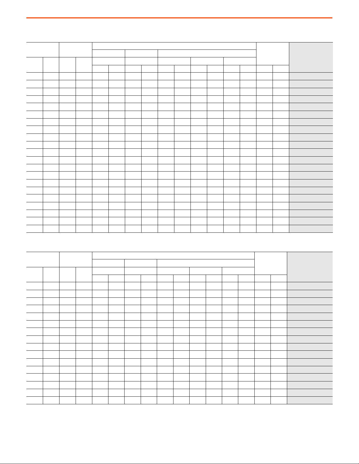
Product Selection Tables
The PowerFlex 7000 drive selection tables are based on two types of drive service duty ratings.
1. Normal Duty (110% overload for 1 minute, once every 10 minutes)
• Used for Variable Torque (VT) applications only. Drives with this rating are designed for 100% continuous operation, with 110%
overload for 1 minute, once every 10 minutes.
2. Heavy Duty (150% for 1 minute, once every 10 minutes)
• Used for Constant Torque (CT) or Variable Torque (VT) applications. Drives with this rating are designed for 100% continuous
operation, with 150% overload for 1 minute, once every 10 minutes.
PowerFlex 7000 Drives with ArcShield Technology
Direct-to-Drive/Normal Duty
2.4 kV 60 Hz
Output Current
[A]
Cont. 1 Min. kW Hp
46 51 150 200 3300 129.9 1000 39.4 2318 91.3 978 38.5 3296 129.8 3975 8763 7000-A__A_-RPDTD
53 58 168 225 3300 129.9 1000 39.4 2318 91.3 978 38.5 3296 129.8 3975 8763 7000-A__A_-RPDTD
61 67 187 250 3300 129.9 1000 39.4 2318 91.3 978 38.5 3296 129.8 4031 8887 7000-A__A_-RPDTD
70 77 225 300 3300 129.9 1000 39.4 2318 91.3 978 38.5 3296 129.8 4031 8887
81 89 261 350 3300 129.9 1000 39.4 2318 91.3 978 38.5 3296 129.8 4301 9482 7000-A__A_-RPDTD
93 102 300 400 3300 129.9 1000 39.4 2318 91.3 978 38.5 3296 129.8 4301 9482 7000-A__A_-RPDTD
105 116 335 450 3300 129.9 1000 39.4 2318 91.3 978 38.5 3296 129.8 4411 9725
120 132 373 500 3300 129.9 1000 39.4 2318 91.3 978 38.5 3296 129.8 4411 9725 7000-A__A_-RPDTD
140 154 450 600 3300 129.9 1000 39.4 2318 91.3 978 38.5 3296 129.8 4551 10033 7000-A__A_-RPDTD
160 176 522 700 3300 129.9 1000 39.4 2318 91.3 978 38.5 3296 129.8 4637 10223
185 204 600 800 3500 137.8 1000 39.4 2318 91.3 978 38.5 3296 129.8 4410 9722 7000-A__A_-RPDTD
215 237 670 900 3500 137.8 1000 39.4 2318 91.3 978 38.5 3296 129.8 4410 9722 7000-A__A_-RPDTD
250 275 750 1000 3500 137.8 1000 39.4 2318 91.3 978 38.5 3296 129.8 4410 9722
285 314 933 1250 3500 137.8 1000 39.4 2318 91.3 978 38.5 3296 129.8 4410 9722 7000-A__A_-RPDTD
325 358 1120 1500 3500 137.8 1000 39.4 2318 91.3 978 38.5 3296 129.8 4410 9722 7000-A__A_-RPDTD
375 413 1300 1750 3500 137.8 1000 39.4 2318 91.3 978 38.5 3296 129.8 4410 9722
430 473 1500 2000 3900 153.5 1000 39.4 2318 91.3 978 38.5 3296 129.8 6410 14132 7000-E__A__ D-RPDTD
Typical Motor
Power Rating
Width Depth Height
W D H1 H2 H
mm in. mm in. mm in. mm in. mm in. kg lb
Approx Dimensions
Approx Weight
Base Catalog Number
7000-A__A_-RPDTD
7000-A__A_-RPDTD
7000-A__A_-RPDTD
7000-A__A_-RPDTD
7000-E__A__ D-RPDTD
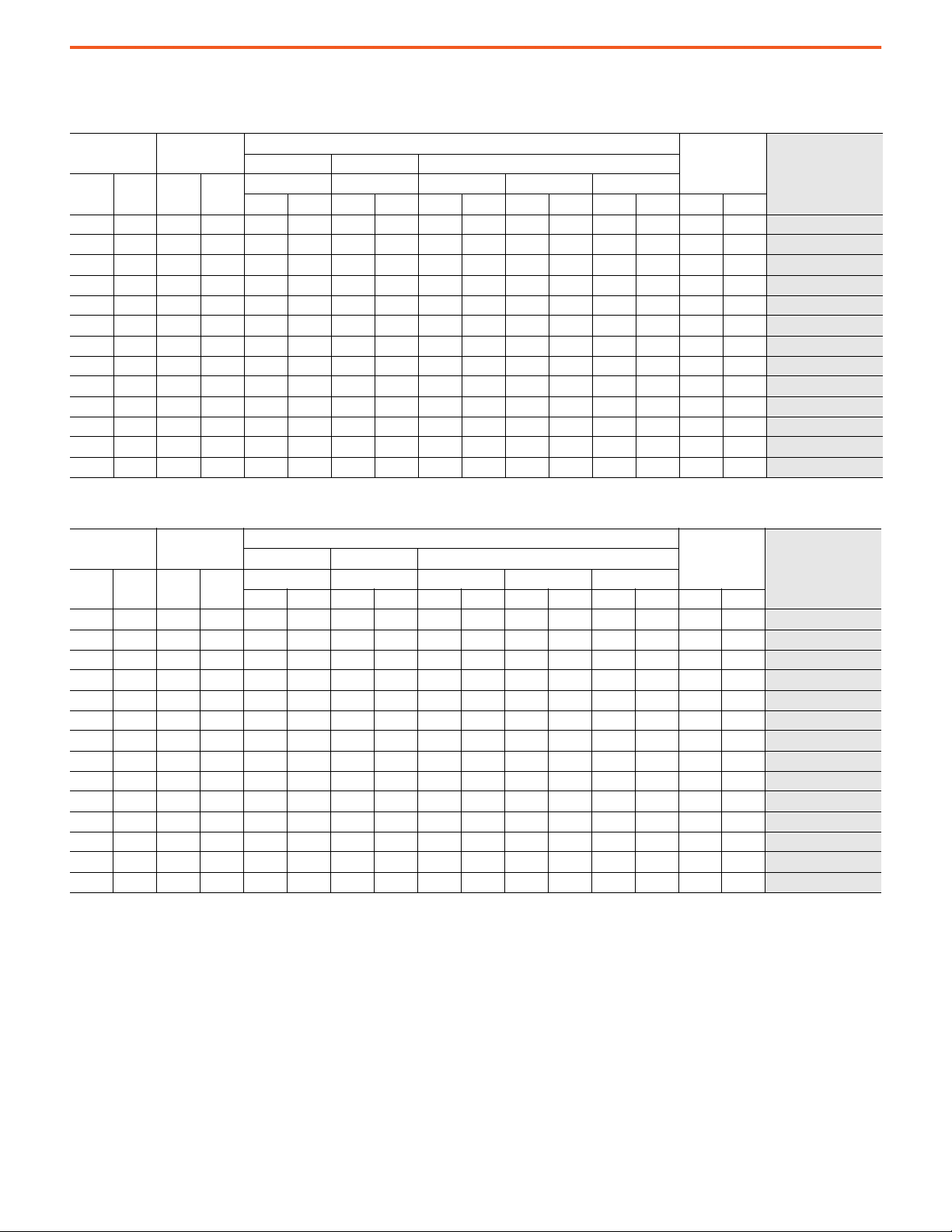
3.3 kV 50 Hz
Output Current
[A]
Cont. 1 Min. kW Hp
46 51 187 250 3700 145.7 1000 39.4 2318 91.3 978 38.5 3296 129.8 4915 10836
53 58 225 300 3700 145.7 1000 39.4 2318 91.3 978 38.5 3296 129.8 4915 10836
61 67 261 350 3700 145.7 1000 39.4 2318 91.3 978 38.5 3296 129.8 5021 11069
70 77 300 400 3700 145.7 1000 39.4 2318 91.3 978 38.5 3296 129.8 5021 11069
81 89 373 500 3700 145.7 1000 39.4 2318 91.3 978 38.5 3296 129.8 5201 11466
93 102 410 550 3700 145.7 1000 39.4 2318 91.3 978 38.5 3296 129.8 5201 11466
105 116 450 600 3700 145.7 1000 39.4 2318 91.3 978 38.5 3296 129.8 5431 11973
120 132 560 750 3700 145.7 1000 39.4 2318 91.3 978 38.5 3296 129.8 5431 11973
140 154 600 800 3700 145.7 1000 39.4 2318 91.3 978 38.5 3296 129.8 5511 12150
160 176 750 1000 3700 145.7 1000 39.4 2318 91.3 978 38.5 3296 129.8 5705 12577
185 204 820 1100 3700 145.7 1000 39.4 2318 91.3 978 38.5 3296 129.8 5705 12577
215 237 933 1250 3700 145.7 1000 39.4 2318 91.3 978 38.5 3296 129.8 5705 12577
250 275 1120 1500 3700 145.7 1000 39.4 2318 91.3 978 38.5 3296 129.8 5705 12577
285 314 1300 1750 3900 153.5 1000 39.4 2318 91.3 978 38.5 3296 129.8 6410 14132
325 358 1500 2000 3900 153.5 1000 39.4 2318 91.3 978 38.5 3296 129.8 6410 14132
375 413 1865 2500 3900 153.5 1000 39.4 2318 91.3 978 38.5 3296 129.8 6410 14132
430 473 2050 2750 4100 161.4 1000 39.4 2318 91.3 978 38.5 3296 129.8 7501 16537
Typical Motor
Power Rating
Width Depth Height
W D H1 H2 H
mm in. mm in. mm in. mm in. mm in. kg lb
Approx Dimensions
Approx Weight
Base Catalog Number
7000-A__C_Y-RPDTD
7000-A__C_Y-RPDTD
7000-A__C_Y-RPDTD
7000-A__C_Y-RPDTD
7000-A__C_Y-RPDTD
7000-A__C_Y-RPDTD
7000-A__C_Y-RPDTD
7000-A__C_Y-RPDTD
7000-A__C_Y-RPDTD
7000-A__C_D-RPDTD
7000-A__C_D-RPDTD
7000-A__C_D-RPDTD
7000-A__C_D-RPDTD
7000-A__C_D-RPDTD
7000-A__C_D-RPDTD
7000-E__C__ D-RPDTD
7000-E__C__ D-RPDTD
Rockwell Automation Publication 7000-TD010A-EN-P - March 2021 13

PowerFlex 7000 Medium Voltage AC Drives Technical Data
4.16 kV 60 Hz
Output Current
[A]
Cont. 1 Min. kW Hp
46 51 261 350 3700 145.7 1000 39.4 2318 91.3 978 38.5 3296 129.8 4915 10836
53 58 300 400 3700 145.7 1000 39.4 2318 91.3 978 38.5 3296 129.8 4915 10836
61 67 335 450 3700 145.7 1000 39.4 2318 91.3 978 38.5 3296 129.8 5021 11069
70 77 373 500 3700 145.7 1000 39.4 2318 91.3 978 38.5 3296 129.8 5021 11069
81 89 450 600 3700 145.7 1000 39.4 2318 91.3 978 38.5 3296 129.8 5201 11466 7000-A__E_-RPDTD
93 102 522 700 3700 145.7 1000 39.4 2318 91.3 978 38.5 3296 129.8 5201 11466
105 116 600 800 3700 145.7 1000 39.4 2318 91.3 978 38.5 3296 129.8 5431 11973
120 132 671 900 3700 145.7 1000 39.4 2318 91.3 978 38.5 3296 129.8 5431 11973 7000-A__E_-RPDTD
140 154 750 1000 3700 145.7 1000 39.4 2318 91.3 978 38.5 3296 129.8 5511 12150
160 176 933 1250 3700 145.7 1000 39.4 2318 91.3 978 38.5 3296 129.8 5705 12577
185 204 1082 1450 3700 145.7 1000 39.4 2318 91.3 978 38.5 3296 129.8 5705 12577 7000-A__E_-RPDTD
215 237 1120 1500 3700 145.7 1000 39.4 2318 91.3 978 38.5 3296 129.8 5705 12577
250 275 1500 2000 3700 145.7 1000 39.4 2318 91.3 978 38.5 3296 129.8 5705 12577
285 314 1680 2250 3900 153.5 1000 39.4 2318 91.3 978 38.5 3296 129.8 6410 14132 7000-A__E_-RPDTD
325 358 1865 2500 3900 153.5 1000 39.4 2318 91.3 978 38.5 3296 129.8 6410 14132
375 413 2240 3000 3900 153.5 1000 39.4 2318 91.3 978 38.5 3296 129.8 6410 14132
430 473 2600 3500 4100 161.4 1000 39.4 2318 91.3 978 38.5 3296 129.8 7501 16537 7000-E__-E_D-RPDTD
Typical Motor
Power Rating
Width Depth Height
W D H1 H2 H
mm in. mm in. mm in. mm in. mm in. kg lb
Approx Dimensions
Approx Weight
Base Catalog Number
7000-A__E_-RPDTD
7000-A__E_-RPDTD
7000-A__E_-RPDTD
7000-A__E_-RPDTD
7000-A__E_-RPDTD
7000-A__E_-RPDTD
7000-A__E_-RPDTD
7000-A__E_-RPDTD
7000-A__E_-RPDTD
7000-A__E_-RPDTD
7000-A__E_-RPDTD
7000-E__-E_D-RPDTD
4.16 kV 50 Hz
Output Current
[A]
Cont. 1 Min. kW Hp
46 51 261 350 3700 145.7 1000 39.4 2318 91.3 978 38.5 3296 129.8 4915 10836
53 58 300 400 3700 145.7 1000 39.4 2318 91.3 978 38.5 3296 129.8 4915 10836 7000-A__E_-RPDTD
61 67 335 450 3700 145.7 1000 39.4 2318 91.3 978 38.5 3296 129.8 5021 11069
70 77 373 500 3700 145.7 1000 39.4 2318 91.3 978 38.5 3296 129.8 5021 11069
81 89 450 600 3700 145.7 1000 39.4 2318 91.3 978 38.5 3296 129.8 5201 11466 7000-A__E_-RPDTD
93 102 522 700 3700 145.7 1000 39.4 2318 91.3 978 38.5 3296 129.8 5201 11466
105 116 600 800 3700 145.7 1000 39.4 2318 91.3 978 38.5 3296 129.8 5431 11973
120 132 671 900 3700 145.7 1000 39.4 2318 91.3 978 38.5 3296 129.8 5431 11973 7000-A__E_-RPDTD
140 154 750 1000 3700 145.7 1000 39.4 2318 91.3 978 38.5 3296 129.8 5511 12150
160 176 933 1250 3700 145.7 1000 39.4 2318 91.3 978 38.5 3296 129.8 5705 12577
185 204 1082 1450 3700 145.7 1000 39.4 2318 91.3 978 38.5 3296 129.8 5705 12577 7000-A__E_-RPDTD
215 237 1120 1500 3700 145.7 1000 39.4 2318 91.3 978 38.5 3296 129.8 5705 12577
250 275 1500 2000 3700 145.7 1000 39.4 2318 91.3 978 38.5 3296 129.8 5705 12577
285 314 1680 2250 3900 153.5 1000 39.4 2318 91.3 978 38.5 3296 129.8 6410 14132 7000-A__E_-RPDTD
325 358 1865 2500 3900 153.5 1000 39.4 2318 91.3 978 38.5 3296 129.8 6410 14132
375 413 2240 3000 4100 161.4 1000 39.4 2318 91.3 978 38.5 3296 129.8 6410 14132
430 473 2600 3500 4100 161.4 1000 39.4 2318 91.3 978 38.5 3296 129.8 7501 16537
Typical Motor
Power Rating
Width Depth Height
W D H1 H2 H
mmin.mmin.mmin.mmin.mmin. kg lb
Approx Dimensions
Approx Weight
Base Catalog Number
7000-A__E_-RPDTD
7000-A__E_-RPDTD
7000-A__E_-RPDTD
7000-A__E_-RPDTD
7000-A__E_-RPDTD
7000-A__E_-RPDTD
7000-A__E_-RPDTD
7000-A__E_-RPDTD
7000-A__E_-RPDTD
7000-A__E_-RPDTD
7000-E__E_D-RPDTD
7000-E__-E_D-RPDTD
14 Rockwell Automation Publication 7000-TD010A-EN-P - March 2021

Direct-to-Drive/Heavy Duty
2.4 kV 60 Hz
PowerFlex 7000 Medium Voltage AC Drives Technical Data
Output Current
[A]
Cont. 1 Min. kW Hp
46 69 150 200 3300 129.9 1000 39.4 2318 91.3 978 38.5 3296 129.8 3975 8763
53 80 168 225 3300 129.9 1000 39.4 2318 91.3 978 38.5 3296 129.8 3975 8763
61 92 187 250 3300 129.9 1000 39.4 2318 91.3 978 38.5 3296 129.8 4031 8887 7000-C__A_-RPDTD
70 105 225 300 3300 129.9 1000 39.4 2318 91.3 978 38.5 3296 129.8 4031 8887
81 122 261 350 3300 129.9 1000 39.4 2318 91.3 978 38.5 3296 129.8 4301 9482
93 140 300 400 3300 129.9 1000 39.4 2318 91.3 978 38.5 3296 129.8 4301 9482 7000-C__A_-RPDTD
105 158 335 450 3300 129.9 1000 39.4 2318 91.3 978 38.5 3296 129.8 4411 9725
120 180 373 500 3300 129.9 1000 39.4 2318 91.3 978 38.5 3296 129.8 4411 9725
140 210 450 600 3300 129.9 1000 39.4 2318 91.3 978 38.5 3296 129.8 4551 10033 7000-C__ A_D-RPDTD
160 240 522 700 3300 129.9 1000 39.4 2318 91.3 978 38.5 3296 129.8 4637 10223
185 278 600 800 3500 137.8 1000 39.4 2318 91.3 978 38.5 3296 129.8 4410 9722
215 323 670 900 3500 137.8 1000 39.4 2318 91.3 978 38.5 3296 129.8 4410 9722 7000-C__ A_D-RPDTD
250 375 750 1000 3700 145.7 1000 39.4 2318 91.3 978 38.5 3296 129.8 4410 9722
Typical Motor
Power Rating
Width Depth Height
W D H1 H2 H
mm in. mm in. mm in. mm in. mm in. kg lb
Approx Dimensions
Approx Weight
Base Catalog Number
7000-C__A_-RPDTD
7000-C__A_-RPDTD
7000-C__A_-RPDTD
7000-C__A_-RPDTD
7000-C__A_-RPDTD
7000-C__A_-RPDTD
7000-C__ A_D-RPDTD
7000-C__ A_D-RPDTD
7000-C__ A_D-RPDTD
3.3 kV 50 Hz
Output Current
[A]
Cont. 1 Min. kW Hp
46 69 187 250 3700 145.7 1000 39.4 2318 91.3 978 38.5 3296 129.8 4915 10836
53 80 225 300 3700 145.7 1000 39.4 2318 91.3 978 38.5 3296 129.8 4915 10836
61 92 261 350 3700 145.7 1000 39.4 2318 91.3 978 38.5 3296 129.8 5021 11069
70 105 300 400 3700 145.7 1000 39.4 2318 91.3 978 38.5 3296 129.8 5021 11069 7000-C__C_Y-RPDTD
81 122 373 500 3700 145.7 1000 39.4 2318 91.3 978 38.5 3296 129.8 5201 11466
93 140 410 550 3700 145.7 1000 39.4 2318 91.3 978 38.5 3296 129.8 5201 11466
105 158 450 600 3700 145.7 1000 39.4 2318 91.3 978 38.5 3296 129.8 5431 11973 7000-C__C_D-RPDTD
120 180 560 750 3700 145.7 1000 39.4 2318 91.3 978 38.5 3296 129.8 5431 11973
140 210 600 800 3700 145.7 1000 39.4 2318 91.3 978 38.5 3296 129.8 5511 12150
160 240 750 1000 3900 153.5 1000 39.4 2318 91.3 978 38.5 3296 129.8 5705 12577 7000-C__C_D-RPDTD
185 278 820 1100 3900 153.5 1000 39.4 2318 91.3 978 38.5 3296 129.8 5705 12577
215 323 933 1250 3900 153.5 1000 39.4 2318 91.3 978 38.5 3296 129.8 5705 12577
Typical Motor
Power Rating
Width Depth Height
W D H1 H2 H
mmin.mmin.mmin.mmin.mmin. kg lb
Approx Dimensions
Approx Weight
Base Catalog Number
7000-C__C_Y-RPDTD
7000-C__C_Y-RPDTD
7000-C__C_Y-RPDTD
7000-C__C_Y-RPDTD
7000-C__C_Y-RPDTD
7000-C__C_D-RPDTD
7000-C__C_D-RPDTD
7000-C__C_D-RPDTD
7000-C__C_D-RPDTD
Rockwell Automation Publication 7000-TD010A-EN-P - March 2021 15

PowerFlex 7000 Medium Voltage AC Drives Technical Data
4.16 kV 60 Hz
Output Current
[A]
Cont. 1 Min. kW Hp
46 69 261 350 3500 137.8 1000 39.4 2318 91.3 978 38.5 3296 129.8 4915 10836
53 80 300 400 3500 137.8 1000 39.4 2318 91.3 978 38.5 3296 129.8 4915 10836
61 92 335 450 3500 137.8 1000 39.4 2318 91.3 978 38.5 3296 129.8 5021 11069
70 105 373 500 3500 137.8 1000 39.4 2318 91.3 978 38.5 3296 129.8 5021 11069
81 122 450 600 3500 137.8 1000 39.4 2318 91.3 978 38.5 3296 129.8 5201 11466 7000-C__E_Y-RPDTD
93 140 522 700 3500 137.8 1000 39.4 2318 91.3 978 38.5 3296 129.8 5201 11466
105 158 600 800 3500 137.8 1000 39.4 2318 91.3 978 38.5 3296 129.8 5431 11973
120 180 671 900 3500 137.8 1000 39.4 2318 91.3 978 38.5 3296 129.8 5431 11973 7000-C__E_Y-RPDTD
140 210 750 1000 3700 145.7 1000 39.4 2318 91.3 978 38.5 3296 129.8 5511 12150
160 240 933 1250 3900 153.5 1000 39.4 2318 91.3 978 38.5 3296 129.8 5705 12577
185 278 1082 1450 3900 153.5 1000 39.4 2318 91.3 978 38.5 3296 129.8 5705 12577 7000-C__E_Y-RPDTD
215 323 1120 1500 3900 153.5 1000 39.4 2318 91.3 978 38.5 3296 129.8 5705 12577
Typical Motor
Power Rating
Width Depth Height
W D H1 H2 H
mmin.mmin.mmin.mmin.mmin. kg lb
Approx Dimensions
Approx Weight
Base Catalog Number
7000-C__E_Y-RPDTD
7000-C__E_Y-RPDTD
7000-C__E_Y-RPDTD
7000-C__E_Y-RPDTD
7000-C__E_Y-RPDTD
7000-C__E_Y-RPDTD
7000-C__E_Y-RPDTD
7000-C__E_Y-RPDTD
7000-C__E_Y-RPDTD
4.16 kV 50 Hz
Output Current
[A]
Cont. 1 Min. kW Hp
46 69 261 350 3700 145.7 1000 39.4 2318 91.3 978 38.5 3296 129.8 4915 10836
53 80 300 400 3700 145.7 1000 39.4 2318 91.3 978 38.5 3296 129.8 4915 10836
61 92 335 450 3700 145.7 1000 39.4 2318 91.3 978 38.5 3296 129.8 5021 11069
70 105 373 500 3700 145.7 1000 39.4 2318 91.3 978 38.5 3296 129.8 5021 11069 7000-C__E_Y-RPDTD
81 122 450 600 3700 145.7 1000 39.4 2318 91.3 978 38.5 3296 129.8 5201 11466
93 140 522 700 3700 145.7 1000 39.4 2318 91.3 978 38.5 3296 129.8 5201 11466
105 158 600 800 3700 145.7 1000 39.4 2318 91.3 978 38.5 3296 129.8 5431 11973 7000-C__E_D-RPDTD
120 180 671 900 3700 145.7 1000 39.4 2318 91.3 978 38.5 3296 129.8 5431 11973
140 210 750 1000 3900 153.5 1000 39.4 2318 91.3 978 38.5 3296 129.8 5511 12150
160 240 933 1250 3900 153.5 1000 39.4 2318 91.3 978 38.5 3296 129.8 5705 12577 7000-C__E_D-RPDTD
185 278 1082 1450 3900 153.5 1000 39.4 2318 91.3 978 38.5 3296 129.8 5705 12577
215 323 1120 1500 3900 153.5 1000 39.4 2318 91.3 978 38.5 3296 129.8 5705 12577
Typical Motor
Power Rating
Width Depth Height
W D H1 H2 H
mm in. mm in. mm in. mm in. mm in. kg lb
Approx Dimensions
Approx Weight
Base Catalog Number
7000-C__E_Y-RPDTD
7000-C__E_Y-RPDTD
7000-C__E_Y-RPDTD
7000-C__E_Y-RPDTD
7000-C__E_D-RPDTD
7000-C__E_D-RPDTD
7000-C__E_D-RPDTD
7000-C__E_D-RPDTD
7000-C__E_D-RPDTD
Dimensions and weights that are shown are for the drive only and are meant to be used with an input starter in a new or existing AllenBradley medium voltage MCC lineup. See the input starter dimensions and weights that are shown on pages 9
…10 to create a fully integrated,
standalone drive system configuration.
16 Rockwell Automation Publication 7000-TD010A-EN-P - March 2021

PowerFlex 7000 Air-cooled Drives
Direct-to-Drive/Normal Duty
2.4 kV 60 Hz
PowerFlex 7000 Medium Voltage AC Drives Technical Data
Output Current
[A]
Cont. 1 Min. kW Hp
46 51 150 200 2400 94.5 1000 39.4 2318 91.3 325 12.8 2643 104.1 2955 6515
53 58 168 225 2400 94.5 1000 39.4 2318 91.3 325 12.8 2643 104.1 2955 6515 7000A-A DA_-RPDTD
61 67 187 250 2400 94.5 1000 39.4 2318 91.3 325 12.8 2643 104.1 2955 6515
70 77 225 300 2400 94.5 1000 39.4 2318 91.3 325 12.8 2643 104.1 2955 6515
81 89 261 350 2400 94.5 1000 39.4 2318 91.3 325 12.8 2643 104.1 2955 6515 7000A-A DA_-RPDTD
93 102 300 400 2400 94.5 1000 39.4 2318 91.3 325 12.8 2643 104.1 2955 6515
105 116 335 450 2400 94.5 1000 39.4 2318 91.3 325 12.8 2643 104.1 2955 6515
120 132 373 500 2400 94.5 1000 39.4 2318 91.3 325 12.8 2643 104.1 2955 6515 7000A-A DA_-RPDTD
140 154 450 600 2400 94.5 1000 39.4 2318 91.3 325 12.8 2643 104.1 2955 6515
160 176 522 700 3300 129.9 1000 39.4 2318 91.3 325 12.8 2643 104.1 4546 10022
185 204 600 800 3500 137.8 1000 39.4 2318 91.3 325 12.8 2643 104.1 4319 9522 7000-A DA_-RPDTD
215 237 670 900 3500 137.8 1000 39.4 2318 91.3 325 12.8 2643 104.1 4319 9522
250 275 750 1000 3500 137.8 1000 39.4 2318 91.3 325 12.8 2643 104.1 4319 9522
285 314 933 1250 3500 137.8 1000 39.4 2318 91.3 325 12.8 2643 104.1 4319 9522 7000-A DA_-RPDTD
325 358 1120 1500 3500 137.8 1000 39.4 2318 91.3 325 12.8 2643 104.1 4319 9522
375 413 1300 1750 3500 137.8 1000 39.4 2318 91.3 325 12.8 2643 104.1 4319 9522
430 473 1500 2000 3900 153.5 1000 39.4 2318 91.3 325 12.8 2643 104.1 6319 13931 7000-E430DA D-RPDTD
Typical Motor
Power Rating
Width Depth Height
W D H1 H2 H
mm in. mm in. mm in. mm in. mm in. kg lb
Approx Dimensions
Approx Weight
Base Catalog Number
7000A-A DA_-RPDTD
7000A-A DA_-RPDTD
7000A-A DA_-RPDTD
7000A-A DA_-RPDTD
7000A-A DA_-RPDTD
7000A-A DA_-RPDTD
7000-A DA_-RPDTD
7000-A DA_-RPDTD
7000-A DA_-RPDTD
7000-A DA_-RPDTD
7000-E375DA D-RPDTD
3.3 kV 50 Hz
Output Current
[A]
Cont. 1 Min. kW Hp
46 51 187 250 2400 94.5 1000 39.4 2318 91.3 325 12.8 2643 104.1 2955 6515
53 58 225 300 2400 94.5 1000 39.4 2318 91.3 325 12.8 2643 104.1 2955 6515
61 67 261 350 2400 94.5 1000 39.4 2318 91.3 325 12.8 2643 104.1 2955 6515
70 77 300 400 2400 94.5 1000 39.4 2318 91.3 325 12.8 2643 104.1 2955 6515 7000A-A DC_Y-RPDTD
81 89 373 500 2400 94.5 1000 39.4 2318 91.3 325 12.8 2643 104.1 2955 6515
93 102 410 550 2400 94.5 1000 39.4 2318 91.3 325 12.8 2643 104.1 2955 6515
105 116 450 600 2400 94.5 1000 39.4 2318 91.3 325 12.8 2643 104.1 2955 6515 7000A-A DC_Y-RPDTD
120 132 560 750 2400 94.5 1000 39.4 2318 91.3 325 12.8 2643 104.1 2955 6515
140 154 600 800 2400 94.5 1000 39.4 2318 91.3 325 12.8 2643 104.1 2955 6515
160 176 750 1000 3700 145.7 1000 39.4 2318 91.3 325 12.8 2643 104.1 5614 12377 7000-A DC_D-RPDTD
185 204 820 1100 3700 145.7 1000 39.4 2318 91.3 325 12.8 2643 104.1 5614 12377
215 237 933 1250 3700 145.7 1000 39.4 2318 91.3 325 12.8 2643 104.1 5614 12377
250 275 1120 1500 3700 145.7 1000 39.4 2318 91.3 325 12.8 2643 104.1 5614 12377 7000-A DC_D-RPDTD
285 314 1300 1750 3900 153.5 1000 39.4 2318 91.3 325 12.8 2643 104.1 6319 13931
325 358 1500 2000 3900 153.5 1000 39.4 2318 91.3 325 12.8 2643 104.1 6319 13931
375 413 1865 2500 3900 153.5 1000 39.4 2318 91.3 325 12.8 2643 104.1 6319 13931
430 473 2050 2750 4100 161.4 1000 39.4 2318 91.3 325 12.8 2643 104.1 7410 16336 7000-E430DC D-RPDTD
495 545 2400 3250 6634 261.2 1456 57.3 2334 91.9 340 13.4 2674 105.3 10910 24052
575 633 2800 3750 6634 261.2 1456 57.3 2334 91.9 340 13.4 2674 105.3 10910 24052
625 688 3100 4250 6634 261.2 1456 57.3 2334 91.9 340 13.4 2674 105.3 10910 24052 7000-E DC_D-RPDTD
720 792 3600 4750 6634 261.2 1456 57.3 2334 91.9 340 13.4 2674 105.3 10910 24052
Typical Motor
Power Rating
Width Depth Height
W D H1 H2 H
mm in. mm in. mm in. mm in. mm in. kg lb
Approx Dimensions
Approx Weight
Base Catalog Number
7000A-A DC_Y-RPDTD
7000A-A DC_Y-RPDTD
7000A-A DC_Y-RPDTD
7000A-A DC_Y-RPDTD
7000A-A DC_Y-RPDTD
7000A-A DC_Y-RPDTD
7000A-A DC_Y-RPDTD
7000-A DC_D-RPDTD
7000-A DC_D-RPDTD
7000-A DC_D-RPDTD
7000-A DC_D-RPDTD
7000-E375DC D-RPDTD
7000-E DC_D-RPDTD
7000-E DC_D-RPDTD
7000-N720DC_D-RPDTD
Rockwell Automation Publication 7000-TD010A-EN-P - March 2021 17
PowerFlex 7000 Medium Voltage AC Drives Technical Data
4.16 kV 60 Hz
Output Current
[A]
Cont. 1 Min. kW Hp
46 51 261 350 2400 94.5 1000 39.4 2318 91.3 325 12.8 2643 104.1 2955 6515
53 58 300 400 2400 94.5 1000 39.4 2318 91.3 325 12.8 2643 104.1 2955 6515
61 67 335 450 2400 94.5 1000 39.4 2318 91.3 325 12.8 2643 104.1 2955 6515
70 77 373 500 2400 94.5 1000 39.4 2318 91.3 325 12.8 2643 104.1 2955 6515
81 89 450 600 2400 94.5 1000 39.4 2318 91.3 325 12.8 2643 104.1 2955 6515 7000A-A DE_-RPDTD
93 102 522 700 2400 94.5 1000 39.4 2318 91.3 325 12.8 2643 104.1 2955 6515
105 116 600 800 2400 94.5 1000 39.4 2318 91.3 325 12.8 2643 104.1 2955 6515
120 132 671 900 2400 94.5 1000 39.4 2318 91.3 325 12.8 2643 104.1 2955 6515 7000A-A DE_-RPDTD
140 154 750 1000 2400 94.5 1000 39.4 2318 91.3 325 12.8 2643 104.1 2955 6515
160 176 933 1250 3700 145.7 1000 39.4 2318 91.3 325 12.8 2643 104.1 5614 12377
185 204 1082 1450 3700 145.7 1000 39.4 2318 91.3 325 12.8 2643 104.1 5614 12377 7000-A DE_-RPDTD
215 237 1120 1500 3700 145.7 1000 39.4 2318 91.3 325 12.8 2643 104.1 5614 12377
250 275 1500 2000 3700 145.7 1000 39.4 2318 91.3 325 12.8 2643 104.1 5614 12377
285 314 1680 2250 3900 153.5 1000 39.4 2318 91.3 325 12.8 2643 104.1 6319 13931 7000-A DE_-RPDTD
325 358 1865 2500 3900 153.5 1000 39.4 2318 91.3 325 12.8 2643 104.1 6319 13931
375 413 2240 3000 3900 153.5 1000 39.4 2318 91 .3 32 5 12.8 2643 104 .1 6 319 139 31
430 473 2600 3500 4100 161.4 1000 39.4 2318 91.3 325 12.8 2643 104.1 7410 16336 7000-E -DE_D-RPDTD
495 545 3000 4000 6634 261.2 1456 57.3 2334 91.9 340 13.4 2674 105.3 10910 24052
575 633 3360 4500 6634 261.2 1456 57.3 2334 91.9 340 13.4 2674 105.3 10910 24052
625 688 3730 5000 6634 261.2 1456 57.3 2334 91.9 340 13.4 2674 105.3 10910 24052 7000-E -DE_D-RPDTD
720 792 4400 5750 6634 261.2 1456 57.3 2334 91.9 340 13.4 2674 105.3 10910 24052
Typical Motor
Power Rating
Width Depth Height
W D H1 H2 H
mm in. mm in. mm in. mm in. mm in. kg lb
Approx Dimensions
Approx Weight
Base Catalog Number
7000A-A DE_-RPDTD
7000A-A DE_-RPDTD
7000A-A DE_-RPDTD
7000A-A DE_-RPDTD
7000A-A DE_-RPDTD
7000A-A DE_-RPDTD
7000A-A DE_-RPDTD
7000-A DE_-RPDTD
7000-A DE_-RPDTD
7000-A DE_-RPDTD
7000-A DE_-RPDTD
7000-E -DE_D-RPDTD
7000-E -DE_D-RPDTD
7000-E -DE_D-RPDTD
7000-N720E D-RPDTD
4.16 kV 50 Hz
Output Current
[A]
Cont. 1 Min. kW Hp
46 51 261 350 2400 94.5 1000 39.4 2318 91.3 325 12.8 2643 104.1 2955 6515
53 58 300 400 2400 94.5 1000 39.4 2318 91.3 325 12.8 2643 104.1 2955 6515
61 67 335 450 2400 94.5 1000 39.4 2318 91.3 325 12.8 2643 104.1 2955 6515
70 77 373 500 2400 94.5 1000 39.4 2318 91.3 325 12.8 2643 104.1 2955 6515 7000A-A DE_-RPDTD
81 89 450 600 2400 94.5 1000 39.4 2318 91.3 325 12.8 2643 104.1 2955 6515
93 102 522 700 2400 94.5 1000 39.4 2318 91.3 325 12.8 2643 104.1 2955 6515
105 116 600 800 2400 94.5 1000 39.4 2318 91.3 325 12.8 2643 104.1 2955 6515 7000A-A DE_-RPDTD
120 132 671 900 2400 94.5 1000 39.4 2318 91.3 325 12.8 2643 104.1 2955 6515
140 154 750 1000 2400 94.5 1000 39.4 2318 91.3 325 12.8 2643 104.1 2955 6515
160 176 933 1250 3700 145.7 1000 39.4 2318 91.3 325 12.8 2643 104.1 5614 12377 7000-A DE_-RPDTD
185 204 1082 1450 3700 145.7 1000 39.4 2318 91.3 325 12.8 2643 104.1 5614 12377
215 237 1120 1500 3700 145.7 1000 39.4 2318 91.3 325 12.8 2643 104.1 5614 12377
250 275 1500 2000 3700 145.7 1000 39.4 2318 91.3 325 12.8 2643 104.1 5614 12377
285 314 1680 2250 3900 153.5 1000 39.4 2318 91.3 325 12.8 2643 104.1 6319 13931 7000-A DE_-RPDTD
325 358 1865 2500 3900 153.5 1000 39.4 2318 91.3 325 12.8 2643 104.1 6319 13931
375 413 2240 3000 4100 161.4 1000 39.4 2318 91.3 325 12.8 2643 104.1 7410 16336
Typical Motor
Power Rating
Width Depth Height
W D H1 H2 H
mm in. mm in. mm in. mm in. mm in. kg lb
Approx Dimensions
Approx Weight
Base Catalog Number
7000A-A DE_-RPDTD
7000A-A DE_-RPDTD
7000A-A DE_-RPDTD
7000A-A DE_-RPDTD
7000A-A DE_-RPDTD
7000A-A DE_-RPDTD
7000A-A DE_-RPDTD
7000-A DE_-RPDTD
7000-A DE_-RPDTD
7000-A DE_-RPDTD
7000-A DE_-RPDTD
7000-E375-DE D-RPDTD
18 Rockwell Automation Publication 7000-TD010A-EN-P - March 2021

6.6 kV 60 Hz
PowerFlex 7000 Medium Voltage AC Drives Technical Data
Output Current
[A]
Cont. 1 Min. kW Hp
40 44 400 500 2800 110.2 1000 39.4 2318 91.3 325 12.8 2643 104.1 3410 7518
46 51 410 550 2800 110.2 1000 39.4 2318 91.3 325 12.8 2643 104.1 3410 7518
53 58 450 600 2800 110.2 1000 39.4 2318 91.3 325 12.8 2643 104.1 3410 7518
61 67 560 750 2800 110.2 1000 39.4 2318 91.3 325 12.8 2643 104.1 3410 7518
70 77 671 900 2800 110.2 1000 39.4 2318 91.3 325 12.8 2643 104.1 3410 7518 7000A-A DJY-RPDTD
81 89 750 1000 2800 110.2 1000 39.4 2318 91.3 325 12.8 2643 104.1 3410 7518
93 102 895 1200 2800 110.2 1000 39.4 2318 91.3 325 12.8 2643 104.1 3410 7518
105 116 933 1250 3900 153.5 1000 39.4 2318 91.3 325 12.8 2643 104.1 4773 10523 7000-A DJ_D-RPDTD
120 132 1120 1500 3900 153.5 1000 39.4 2318 91.3 325 12.8 2643 104.1 4773 10523
140 154 1300 1750 4100 161.4 1000 39.4 2318 91.3 325 12.8 2643 104.1 7410 16336
160 176 1500 2000 4100 161.4 1000 39.4 2318 91.3 325 12.8 2643 104.1 7410 16336 7000-A DJ_D-RPDTD
185 204 1680 2250 4100 161.4 1000 39.4 2318 91.3 325 12.8 2643 104.1 7410 16336
215 237 2050 2750 4100 161.4 1000 39.4 2318 91.3 325 12.8 2643 104.1 7410 16336
250 275 2240 3000 4300 169.3 1000 39.4 2318 91.3 325 12.8 2643 104.1 7410 16336 7000-A DJ_D-RPDTD
285 314 2600 3500 4300 169.3 1000 39.4 2318 91.3 325 12.8 2643 104.1 7410 16336
Typical Motor
Power Rating
Width Depth Height
W D H1 H2 H
mm in. mm in. mm in. mm in. mm in. kg lb
Approx Dimensions
Approx Weight
Base Catalog Number
7000A-A DJY-RPDTD
7000A-A DJY-RPDTD
7000A-A DJY-RPDTD
7000A-A DJY-RPDTD
7000A-A DJY-RPDTD
7000A-A DJY-RPDTD
7000-A DJ_D-RPDTD
7000-A DJ_D-RPDTD
7000-A DJ_D-RPDTD
7000-A DJ_D-RPDTD
7000-A DJ_D-RPDTD
6.6 kV 50 Hz
Output Current
[A]
Cont. 1 Min. kW Hp
40 44 400 500 2800 110.2 1000 39.4 2318 91.3 325 12.8 2643 104.1 3410 7518
46 51 410 550 2800 110.2 1000 39.4 2318 91.3 325 12.8 2643 104.1 3410 7518
53 58 450 600 2800 110.2 1000 39.4 2318 91.3 325 12.8 2643 104.1 3410 7518
61 67 560 750 2800 110.2 1000 39.4 2318 91.3 325 12.8 2643 104.1 3410 7518 7000A-A DJY-RPDTD
70 77 671 900 2800 110.2 1000 39.4 2318 91.3 325 12.8 2643 104.1 3410 7518
81 89 750 1000 2800 110.2 1000 39.4 2318 91.3 325 12.8 2643 104.1 3410 7518
93 102 895 1200 2800 110.2 1000 39.4 2318 91.3 325 12.8 2643 104.1 3410 7518 7000A-A DJY-RPDTD
105 116 933 1250 3900 153.5 1000 39.4 2318 91.3 325 12.8 2643 104.1 4773 10523
120 132 1120 1500 3900 153.5 1000 39.4 2318 91.3 325 12.8 2643 104.1 4773 10523
140 154 1300 1750 4100 161.4 1000 39.4 2318 91.3 325 12.8 2643 104.1 7410 16336 7000-A DJ_D-RPDTD
160 176 1500 2000 4100 161.4 1000 39.4 2318 91.3 325 12.8 2643 104.1 7410 16336
185 204 1680 2250 4100 161.4 1000 39.4 2318 91.3 325 12.8 2643 104.1 7410 16336
215 237 2050 2750 4100 161.4 1000 39.4 2318 91.3 325 12.8 2643 104.1 7410 16336 7000-A DJ_D-RPDTD
250 275 2240 3000 4300 169.3 1000 39.4 2318 91.3 325 12.8 2643 104.1 7410 16336
285 314 2600 3500 4300 169.3 1000 39.4 2318 91.3 325 12.8 2643 104.1 7410 16336
325 358 3000 4000 8491 334.3 1456 57.3 2413 95.0 325 12.8 2738 107.8 10400 22928 7000-E DJ_D-RPDTD
375 413 3730 5000 9291 365.8 1456 57.3 2413 95.0 325 12.8 2738 107.8 13500 29762
430 473 4100 5500 9291 365.8 1456 57.3 2413 95.0 325 12.8 2738 107.8 13500 29762
495 545 4850 6500 9291 365.8 1456 57.3 2413 95.0 325 12.8 2738 107.8 13500 29762
575 633 5595 7000 9291 365.8 1456 57.3 2413 95.0 325 12.8 2738 107.8 13500 29762 7000-E DJ_D-RPDTD
625 688 6000 8000 9291 365.8 1456 57.3 2413 95.0 325 12.8 2738 107.8 13500 29762
Typical Motor
Power Rating
Width Depth Height
W D H1 H2 H
mm in. mm in. mm in. mm in. mm in. kg lb
Approx Dimensions
Approx Weight
Base Catalog Number
7000A-A DJY-RPDTD
7000A-A DJY-RPDTD
7000A-A DJY-RPDTD
7000A-A DJY-RPDTD
7000A-A DJY-RPDTD
7000-A DJ_D-RPDTD
7000-A DJ_D-RPDTD
7000-A DJ_D-RPDTD
7000-A DJ_D-RPDTD
7000-A DJ_D-RPDTD
7000-A DJ_D-RPDTD
7000-E DJ_D-RPDTD
7000-E DJ_D-RPDTD
7000-E DJ_D-RPDTD
7000-N_DJ_D-RPDTD
Rockwell Automation Publication 7000-TD010A-EN-P - March 2021 19

PowerFlex 7000 Medium Voltage AC Drives Technical Data
Direct-to-Drive/Heavy Duty
2.4 kV 60 Hz
Output Current
[A]
Cont. 1 Min. kW Hp
46 69 150 200 2400 94.5 1000 39.4 2318 91.3 325 12.8 2643 104.1 2955 6515
53 80 168 225 2400 94.5 1000 39.4 2318 91.3 325 12.8 2643 104.1 2955 6515
61 92 187 250 2400 94.5 1000 39.4 2318 91.3 325 12.8 2643 104.1 2955 6515 7000A-C DA_-RPDTD
70 105 225 300 2400 94.5 1000 39.4 2318 91.3 325 12.8 2643 104.1 2955 6515
81 122 261 350 2400 94.5 1000 39.4 2318 91.3 325 12.8 2643 104.1 2955 6515
93 140 300 400 2400 94.5 1000 39.4 2318 91.3 325 12.8 2643 104.1 2955 6515 7000A-C DA_-RPDTD
105 158 335 450 2400 94.5 1000 39.4 2318 91.3 325 12.8 2643 104.1 2955 6515
120 180 373 500 2400 94.5 1000 39.4 2318 91.3 325 12.8 2643 104.1 2955 6515
140 210 450 600 3300 129.9 1000 39.4 2318 91.3 325 12.8 2643 104.1 4546 10022 7000-C DA_D-RPDTD
160 240 522 700 3300 129.9 1000 39.4 2318 91.3 325 12.8 2643 104.1 4546 10022
185 278 600 800 3500 137.8 1000 39.4 2318 91.3 325 12.8 2643 104.1 4319 9522
215 323 670 900 3500 137.8 1000 39.4 2318 91.3 325 12.8 2643 104.1 4319 9522 7000-C DA_D-RPDTD
250 375 750 1000 3700 145.7 1000 39.4 2318 91.3 325 12.8 2643 104.1 5614 12377
Typical Motor
Power Rating
Width Depth Height
W D H1 H2 H
mm in. mm in. mm in. mm in. mm in. kg lb
Approx Dimensions
Approx Weight
Base Catalog Number
7000A-C DA_-RPDTD
7000A-C DA_-RPDTD
7000A-C DA_-RPDTD
7000A-C DA_-RPDTD
7000A-C DA_-RPDTD
7000A-C DA_-RPDTD
7000-C DA_D-RPDTD
7000-C DA_D-RPDTD
7000-C DA_D-RPDTD
3.3 kV 50 Hz
Output Current
[A]
Cont. 1 Min. kW Hp
46 69 187 250 2400 94.5 1000 39.4 2318 91.3 325 12.8 2643 104.1 2955 6515
53 80 225 300 2400 94.5 1000 39.4 2318 91.3 325 12.8 2643 104.1 2955 6515
61 92 261 350 2400 94.5 1000 39.4 2318 91.3 325 12.8 2643 104.1 2955 6515
70 105 300 400 2400 94.5 1000 39.4 2318 91.3 325 12.8 2643 104.1 2955 6515 7000A-C DC_Y-RPDTD
81 122 373 500 2400 94.5 1000 39.4 2318 91.3 325 12.8 2643 104.1 2955 6515
93 140 410 550 2400 94.5 1000 39.4 2318 91.3 325 12.8 2643 104.1 2955 6515
105 158 450 600 3700 145.7 1000 39.4 2318 91.3 325 12.8 2643 104.1 5614 12377 7000-C DC_D-RPDTD
120 180 560 750 3700 145.7 1000 39.4 2318 91.3 325 12.8 2643 104.1 5614 12377
140 210 600 800 3700 145.7 1000 39.4 2318 91.3 325 12.8 2643 104.1 5614 12377
160 240 750 1000 3900 153.5 1000 39.4 2318 91.3 325 12.8 2643 104.1 6319 13931 7000-C DC_D-RPDTD
185 278 820 1100 3900 153.5 1000 39.4 2318 91.3 325 12.8 2643 104.1 6319 13931
215 323 933 1250 3900 153.5 1000 39.4 2318 91.3 325 12.8 2643 104.1 6319 13931
285 428 1300 1750 6634 261.2 1456 57.3 2334 91.9 340 13.4 2674 105.3 10910 24052 7000-G DC_D-RPDTD
325 488 1500 2000 6634 261.2 1456 57.3 2334 91.9 340 13.4 2674 105.3 10910 24052
Typical Motor
Power Rating
Width Depth Height
W D H1 H2 H
mm in. mm in. mm in. mm in. mm in. kg lb
Approx Dimensions
Approx Weight
Base Catalog Number
7000A-C DC_Y-RPDTD
7000A-C DC_Y-RPDTD
7000A-C DC_Y-RPDTD
7000A-C DC_Y-RPDTD
7000A-C DC_Y-RPDTD
7000-C DC_D-RPDTD
7000-C DC_D-RPDTD
7000-C DC_D-RPDTD
7000-C DC_D-RPDTD
7000-G DC_D-RPDTD
20 Rockwell Automation Publication 7000-TD010A-EN-P - March 2021

4.16kV 60Hz
PowerFlex 7000 Medium Voltage AC Drives Technical Data
Output Current
[A]
Cont. 1 Min. kW Hp
46 69 261 350 2400 94.5 1000 39.4 2318 91.3 325 12.8 2643 104.1 2955 6515
53 80 300 400 2400 94.5 1000 39.4 2318 91.3 325 12.8 2643 104.1 2955 6515
61 92 335 450 2400 94.5 1000 39.4 2318 91.3 325 12.8 2643 104.1 2955 6515
70 105 373 500 2400 94.5 1000 39.4 2318 91.3 325 12.8 2643 104.1 2955 6515
81 122 450 600 2400 94.5 1000 39.4 2318 91.3 325 12.8 2643 104.1 2955 6515 7000A-C DE_Y-RPDTD
93 140 522 700 2400 94.5 1000 39.4 2318 91.3 325 12.8 2643 104.1 2955 6515
105 158 600 800 3500 137.8 1000 39.4 2318 91.3 325 12.8 2643 104.1 4546 10022
120 180 671 900 3500 137.8 1000 39.4 2318 91.3 325 12.8 2643 104.1 4546 10022 7000-C DE_Y-RPDTD
140 210 750 1000 3700 145.7 1000 39.4 2318 91.3 325 12.8 2643 104.1 5614 12377
160 240 933 1250 3900 153.5 1000 39.4 2318 91.3 325 12.8 2643 104.1 6319 13931
185 278 1082 1450 3900 153.5 1000 39.4 2318 91.3 325 12.8 2643 104.1 6319 13931 7000-C DE_Y-RPDTD
215 323 1120 1500 3900 153.5 1000 39.4 2318 91.3 325 12.8 2643 104.1 6319 13931
285 428 1680 2250 6634 261.2 1456 57.3 2334 91.9 340 13.4 2674 105.3 10910 24052
325 488 1865 2500 6634 261.2 1456 57.3 2334 91.9 340 13.4 2674 105.3 10910 24052 7000-G DE_Y-RPDTD
Typical Motor
Power Rating
Width Depth Height
W D H1 H2 H
mm in. mm in. mm in. mm in. mm in. kg lb
Approx Dimensions
Approx Weight
Base Catalog Number
7000A-C DE_Y-RPDTD
7000A-C DE_Y-RPDTD
7000A-C DE_Y-RPDTD
7000A-C DE_Y-RPDTD
7000A-C DE_Y-RPDTD
7000-C DE_Y-RPDTD
7000-C DE_Y-RPDTD
7000-C DE_Y-RPDTD
7000-C DE_Y-RPDTD
7000-G DE_Y-RPDTD
4.6 kV 50 Hz
Output Current
[A]
Cont. 1 Min. kW Hp
46 69 261 350 2400 94.5 1000 39.4 2318 91.3 325 12.8 2643 104.1 2955 6515
53 80 300 400 2400 94.5 1000 39.4 2318 91.3 325 12.8 2643 104.1 2955 6515 7000A-C DE_Y-RPDTD
61 92 335 450 2400 94.5 1000 39.4 2318 91.3 325 12.8 2643 104.1 2955 6515
70 105 373 500 2400 94.5 1000 39.4 2318 91.3 325 12.8 2643 104.1 2955 6515
81 122 450 600 2400 94.5 1000 39.4 2318 91.3 325 12.8 2643 104.1 2955 6515 7000A-C DE_Y-RPDTD
93 140 522 700 3700 145.7 1000 39.4 2318 91.3 325 12.8 2643 104.1 5614 12377
105 158 600 800 3700 145.7 1000 39.4 2318 91.3 325 12.8 2643 104.1 5614 12377
120 180 671 900 3700 145.7 1000 39.4 2318 91.3 325 12.8 2643 104.1 5614 12377 7000-C DE_D-RPDTD
140 210 750 1000 3900 153.5 1000 39.4 2318 91.3 325 12.8 2643 104.1 6319 13931
160 240 933 1250 3900 153.5 1000 39.4 2318 91.3 325 12.8 2643 104.1 6319 13931
185 278 1082 1450 3900 153.5 1000 39.4 2318 91.3 325 12.8 2643 104.1 6319 13931 7000-C DE_D-RPDTD
215 323 1120 1500 3900 153.5 1000 39.4 2318 91.3 325 12.8 2643 104.1 6319 13931
Typical Motor
Power Rating
Width Depth Height
W D H1 H2 H
mmin.mmin.mmin.mmin.mmin. kg lb
Approx Dimensions
Approx Weight
Base Catalog Number
7000A-C DE_Y-RPDTD
7000A-C DE_Y-RPDTD
7000A-C DE_Y-RPDTD
7000-C DE_D-RPDTD
7000-C DE_D-RPDTD
7000-C DE_D-RPDTD
7000-C DE_D-RPDTD
7000-C DE_D-RPDTD
Rockwell Automation Publication 7000-TD010A-EN-P - March 2021 21

PowerFlex 7000 Medium Voltage AC Drives Technical Data
6.6 kV 50/60 Hz
Output Current
[A]
Cont. 1 Min. kW Hp
40 60 400 500 3900 153.5 1000 39.4 2318 91.3 325 12.8 2643 104.1 4773 10523
46 69 410 550 3900 153.5 1000 39.4 2318 91.3 325 12.8 2643 104.1 4773 10523
53 80 450 600 3900 153.5 1000 39.4 2318 91.3 325 12.8 2643 104.1 4773 10523
61 92 560 750 3900 153.5 1000 39.4 2318 91.3 325 12.8 2643 104.1 4773 10523
70 105 671 900 3900 153.5 1000 39.4 2318 91.3 325 12.8 2643 104.1 4773 10523 7000-C AJ_D-RPDTD
81 122 750 1000 4100 161.4 1000 39.4 2318 91.3 325 12.8 2643 104.1 7410 16336
93 140 895 1200 4100 161.4 1000 39.4 2318 91.3 325 12.8 2643 104.1 7410 16336
105 158 933 1250 4100 161.4 1000 39.4 2318 91.3 325 12.8 2643 104.1 7410 16336 7000-C AJ_D-RPDTD
120 180 1120 1500 4100 161.4 1000 39.4 2318 91.3 325 12.8 2643 104.1 7410 16336
140 210 1300 1750 4400 173.2 1000 39.4 2318 91.3 325 12.8 2643 104.1 6637 14632
160 240 1500 2000 4400 173.2 1000 39.4 2318 91.3 325 12.8 2643 104.1 6637 14632 7000-C AJ_D-RPDTD
185 278 1680 2250 4400 173.2 1000 39.4 2318 91.3 325 12.8 2643 104.1 6637 14632
Typical Motor
Power Rating
Width Depth Height
W D H1 H2 H
mm in. mm in. mm in. mm in. mm in. kg lb
Approx Dimensions
Approx Weight
Base Catalog Number
7000-C AJ_D-RPDTD
7000-C AJ_D-RPDTD
7000-C AJ_D-RPDTD
7000-C AJ_D-RPDTD
7000-C AJ_D-RPDTD
7000-C AJ_D-RPDTD
7000-C AJ_D-RPDTD
7000-C AJ_D-RPDTD
7000-C AJ_D-RPDTD
6.6 kV 50 Hz
Output Current
[A]
Cont. 1 Min. kW Hp
215 323 2050 2750 8491 334.3 1456 57.3 2334 91.9 404 15.9 2738 107.8 10400 22928
250 375 2240 3000 8491 334.3 1456 57.3 2334 91.9 404 15.9 2738 107.8 10400 22928
Typical Motor
Power Rating
Width Depth Height
W D H1 H2 H
mm in. mm in. mm in. mm in. mm in. kg lb
Approx Dimensions
Approx Weight
Base Catalog Number
7000-G AJ_D-RPDTD
7000-G AJ_D-RPDTD
22 Rockwell Automation Publication 7000-TD010A-EN-P - March 2021

AFE - Connection to Separate Transformer/Normal Duty
2.4 kV 60 Hz
PowerFlex 7000 Medium Voltage AC Drives Technical Data
Output Current
[A]
Cont. 1 Min. kW Hp
46 51 150 200 2100 82.7 1000 39.4 2318 91.3 325 12.8 2643 104.1 1955 4310
53 58 168 225 2100 82.7 1000 39.4 2318 91.3 325 12.8 2643 104.1 1955 4310
61 67 187 250 2100 82.7 1000 39.4 2318 91.3 325 12.8 2643 104.1 1955 4310 7000A-A DAD_-RPTX
70 77 225 300 2100 82.7 1000 39.4 2318 91.3 325 12.8 2643 104.1 1955 4310
81 89 261 350 2100 82.7 1000 39.4 2318 91.3 325 12.8 2643 104.1 1955 4310
93 102 300 400 2100 82.7 1000 39.4 2318 91.3 325 12.8 2643 104.1 1955 4310 7000A-A DAD_-RPTX
105 116 335 450 2100 82.7 1000 39.4 2318 91.3 325 12.8 2643 104.1 1955 4310
120 132 373 500 2100 82.7 1000 39.4 2318 91.3 325 12.8 2643 104.1 1955 4310
140 154 450 600 2100 82.7 1000 39.4 2318 91.3 325 12.8 2643 104.1 1955 4310 7000A-A DAD_-RPTX
160 176 522 700 2100 82.7 1000 39.4 2318 91.3 325 12.8 2643 104.1 1955 4310
185 204 600 800 2400 94.5 1000 39.4 2318 91.3 325 12.8 2643 104.1 1955 4310
215 237 670 900 2400 94.5 1000 39.4 2318 91.3 325 12.8 2643 104.1 1955 4310 7000-A DA_D-RPTX
250 275 750 1000 2400 94.5 1000 39.4 2318 91.3 325 12.8 2643 104.1 1955 4310
285 314 933 1250 2600 102.4 1000 39.4 2318 91.3 325 12.8 2643 104.1 2160 4762
325 358 1120 1500 2600 102.4 1000 39.4 2318 91.3 325 12.8 2643 104.1 2160 4762 7000-A DA_D-RPTX
375 413 1300 1750 2600 102.4 1000 39.4 2318 91.3 325 12.8 2643 104.1 2160 4762
430 473 1500 2000 2800 110.2 1000 39.4 2318 91.3 325 12.8 2643 104.1 2500 5512
Typical Motor
Power Rating
Width Depth Height
W D H1 H2 H
mm in. mm in. mm in. mm in. mm in. kg lb
Approx Dimensions
Approx Weight
Base Catalog Number
7000A-A DAD_-RPTX
7000A-A DAD_-RPTX
7000A-A DAD_-RPTX
7000A-A DAD_-RPTX
7000A-A DAD_-RPTX
7000A-A DAD_-RPTX
7000A-A DAD_-RPTX
7000-A DA_D-RPTX
7000-A DA_D-RPTX
7000-A DA_D-RPTX
7000-E375-DA D-RPTX
7000-E430-DA D-RPTX
3.3 kV 50 Hz
Output Current
[A]
Cont. 1 Min. kW Hp
46 51 187 250 2100 82.7 1000 39.4 2318 91.3 325 12.8 2643 104.1 1955 4310
53 58 225 300 2100 82.7 1000 39.4 2318 91.3 325 12.8 2643 104.1 1955 4310
61 67 261 350 2100 82.7 1000 39.4 2318 91.3 325 12.8 2643 104.1 1955 4310 7000A-A DCDY-RPTX
70 77 300 400 2100 82.7 1000 39.4 2318 91.3 325 12.8 2643 104.1 1955 4310
81 89 373 500 2100 82.7 1000 39.4 2318 91.3 325 12.8 2643 104.1 1955 4310
93 102 410 550 2100 82.7 1000 39.4 2318 91.3 325 12.8 2643 104.1 1955 4310 7000A-A DCDY-RPTX
105 116 450 600 2100 82.7 1000 39.4 2318 91.3 325 12.8 2643 104.1 1955 4310
120 132 560 750 2100 82.7 1000 39.4 2318 91.3 325 12.8 2643 104.1 1955 4310
140 154 600 800 2100 82.7 1000 39.4 2318 91.3 325 12.8 2643 104.1 1955 4310 7000A-A DCDY-RPTX
160 176 750 1000 2100 82.7 1000 39.4 2318 91.3 325 12.8 2643 104.1 1955 4310
185 204 820 1100 2800 110.2 1000 39.4 2318 91.3 325 12.8 2643 104.1 2364 5212
215 237 933 1250 3000 118.1 1000 39.4 2318 91.3 325 12.8 2643 104.1 2841 6263 7000-A DC_D-RPTX
250 275 1120 1500 3000 118.1 1000 39.4 2318 91.3 325 12.8 2643 104.1 2841 6263
285 314 1300 1750 3000 118.1 1000 39.4 2318 91.3 325 12.8 2643 104.1 2841 6263
325 358 1500 2000 3000 118.1 1000 39.4 2318 91.3 325 12.8 2643 104.1 2841 6263 7000-A DC_D-RPTX
375 413 1865 2500 3000 118.1 1000 39.4 2318 91.3 325 12.8 2643 104.1 2841 6263
430 473 2050 2750 3700 145.7 1000 39.4 2318 91.3 325 12.8 2643 104.1 4091 9019
495 545 2400 3250 6634 261.2 1456 57.3 2334 91.9 340 13.4 2674 105.3 10910 24052
575 633 2800 3750 6634 261.2 1456 57.3 2334 91.9 340 13.4 2674 105.3 10910 24052 7000-E DC_D-RPTX
625 688 3100 4250 6634 261.2 1456 57.3 2334 91.9 340 13.4 2674 105.3 10910 24052
720 792 3600 4750 6634 261.2 1456 57.3 2334 91.9 340 13.4 2674 105.3 10910 24052
Typical Motor
Power Rating
Width Depth Height
W D H1 H2 H
mm in. mm in. mm in. mm in. mm in. kg lb
Approx Dimensions
Approx Weight
Base Catalog Number
7000A-A DCDY-RPTX
7000A-A DCDY-RPTX
7000A-A DCDY-RPTX
7000A-A DCDY-RPTX
7000A-A DCDY-RPTX
7000A-A DCDY-RPTX
7000A-A DCDY-RPTX
7000-A DC_D-RPTX
7000-A DC_D-RPTX
7000-A DC_D-RPTX
7000-E375-DC D-RPTX
7000-E430-DC D-RPTX
7000-E DC_D-RPTX
7000-E DC_D-RPTX
7000-N720DC_D-RPTX
Rockwell Automation Publication 7000-TD010A-EN-P - March 2021 23

PowerFlex 7000 Medium Voltage AC Drives Technical Data
4.16 kV 60 Hz
Output Current
[A]
Cont. 1 Min. kW Hp
46 51 261 350 2100 82.7 1000 39.4 2318 91.3 325 12.8 2643 104.1 1955 4310
53 58 300 400 2100 82.7 1000 39.4 2318 91.3 325 12.8 2643 104.1 1955 4310
61 67 335 450 2100 82.7 1000 39.4 2318 91.3 325 12.8 2643 104.1 1955 4310
70 77 373 500 2100 82.7 1000 39.4 2318 91.3 325 12.8 2643 104.1 1955 4310
81 89 450 600 2100 82.7 1000 39.4 2318 91.3 325 12.8 2643 104.1 1955 4310 7000A-A DED_-RPTX
93 102 522 700 2100 82.7 1000 39.4 2318 91.3 325 12.8 2643 104.1 1955 4310
105 116 600 800 2100 82.7 1000 39.4 2318 91.3 325 12.8 2643 104.1 1955 4310
120 132 671 900 2100 82.7 1000 39.4 2318 91.3 325 12.8 2643 104.1 1955 4310 7000A-A DED_-RPTX
140 154 750 1000 2100 82.7 1000 39.4 2318 91.3 325 12.8 2643 104.1 1955 4310
160 176 933 1250 2100 82.7 1000 39.4 2318 91.3 325 12.8 2643 104.1 1955 4310
185 204 1082 1450 2800 110.2 1000 39.4 2318 91.3 325 12.8 2643 104.1 2500 5512 7000-A DE_D-RPTX
215 237 1120 1500 2800 110.2 1000 39.4 2318 91.3 325 12.8 2643 104.1 2500 5512
250 275 1500 2000 2800 110.2 1000 39.4 2318 91.3 325 12.8 2643 104.1 2500 5512
285 314 1680 2250 3000 118.1 1000 39.4 2318 91.3 325 12.8 2643 104.1 2841 6263 7000-A DE_D-RPTX
325 358 1865 2500 3500 137.8 1000 39.4 2318 91.3 325 12.8 2643 104.1 3864 8519
375 413 2240 3000 3500 137.8 1000 39.4 2318 91.3 325 12.8 2643 104.1 3864 8519
430 473 2600 3500 3700 145.7 1000 39.4 2318 91.3 325 12.8 2643 104.1 4091 9019 7000-E430-DE D-RPTX
495 545 3000 4000 6634 261.2 1456 57.3 2334 91.9 340 13.4 2674 105.3 10910 24052
575 633 3360 4500 6634 261.2 1456 57.3 2334 91.9 340 13.4 2674 105.3 10910 24052
625 688 3730 5000 6634 261.2 1456 57.3 2334 91.9 340 13.4 2674 105.3 10910 24052 7000-E430-DE D-RPTX
720 792 4400 5750 6634 261.2 1456 57.3 2334 91.9 340 13.4 2674 105.3 10910 24052
Typical Motor
Power Rating
Width Depth Height
W D H1 H2 H
mm in. mm in. mm in. mm in. mm in. kg lb
Approx Dimensions
Approx Weight
Base Catalog Number
7000A-A DED_-RPTX
7000A-A DED_-RPTX
7000A-A DED_-RPTX
7000A-A DED_-RPTX
7000A-A DED_-RPTX
7000A-A DED_-RPTX
7000A-A DED_-RPTX
7000A-A DED_-RPTX
7000-A DE_D-RPTX
7000-A DE_D-RPTX
7000-A DE_D-RPTX
7000-E375-DE D-RPTX
7000-E430-DE D-RPTX
7000-E430-DE D-RPTX
7000-N720E D-RPTX
4.16 kV 50 Hz
Output Current
[A]
Cont. 1 Min. kW Hp
46 51 261 350 2100 82.7 1000 39.4 2318 91.3 325 12.8 2643 104.1 1955 4310
53 58 300 400 2100 82.7 1000 39.4 2318 91.3 325 12.8 2643 104.1 1955 4310
61 67 335 450 2100 82.7 1000 39.4 2318 91.3 325 12.8 2643 104.1 1955 4310
70 77 373 500 2100 82.7 1000 39.4 2318 91.3 325 12.8 2643 104.1 1955 4310 7000A-A DED_-RPTX
81 89 450 600 2100 82.7 1000 39.4 2318 91.3 325 12.8 2643 104.1 1955 4310
93 102 522 700 2100 82.7 1000 39.4 2318 91.3 325 12.8 2643 104.1 1955 4310
105 116 600 800 2100 82.7 1000 39.4 2318 91.3 325 12.8 2643 104.1 1955 4310 7000A-A DED_-RPTX
120 132 671 900 2100 82.7 1000 39.4 2318 91.3 325 12.8 2643 104.1 1955 4310
140 154 750 1000 2100 82.7 1000 39.4 2318 91.3 325 12.8 2643 104.1 1955 4310
160 176 933 1250 3000 118.1 1000 39.4 2318 91.3 325 12.8 2643 104.1 2841 6263 7000-A DE_D-RPTX
185 204 1082 1450 3000 118.1 1000 39.4 2318 91.3 325 12.8 2643 104.1 2841 6263
215 237 1120 1500 3000 118.1 1000 39.4 2318 91.3 325 12.8 2643 104.1 2841 6263
250 275 1500 2000 3500 137.8 1000 39.4 2318 91.3 325 12.8 2643 104.1 3864 8519
285 314 1680 2250 3500 137.8 1000 39.4 2318 91.3 325 12.8 2643 104.1 3864 8519 7000-A DE_D-RPTX
325 358 1865 2500 3500 137.8 1000 39.4 2318 91.3 325 12.8 2643 104.1 3864 8519
375 413 2240 3000 3500 137.8 1000 39.4 2318 91.3 325 12.8 2643 104.1 3864 8519
430 473 2600 3500 3700 145.7 1000 39.4 2318 91.3 325 12.8 2643 104.1 4091 9019 7000-E430-DE D-RPTX
Typical Motor
Power Rating
Width Depth Height
W D H1 H2 H
mm in. mm in. mm in. mm in. mm in. kg lb
Approx Dimensions
Approx Weight
Base Catalog Number
7000A-A DED_-RPTX
7000A-A DED_-RPTX
7000A-A DED_-RPTX
7000A-A DED_-RPTX
7000A-A DED_-RPTX
7000A-A DED_-RPTX
7000A-A DED_-RPTX
7000-A DE_D-RPTX
7000-A DE_D-RPTX
7000-A DE_D-RPTX
7000-A DE_D-RPTX
7000-E375-DE D-RPTX
24 Rockwell Automation Publication 7000-TD010A-EN-P - March 2021

6.6 kV 60 Hz
PowerFlex 7000 Medium Voltage AC Drives Technical Data
Output Current
[A]
Cont. 1 Min. kW Hp
40 44 400 500 2400 94.5 1000 39.4 2318 91.3 325 12.8 2643 104.1 2160 4762
46 51 410 550 2400 94.5 1000 39.4 2318 91.3 325 12.8 2643 104.1 2160 4762
53 58 450 600 2400 94.5 1000 39.4 2318 91.3 325 12.8 2643 104.1 2160 4762
61 67 560 750 2400 94.5 1000 39.4 2318 91.3 325 12.8 2643 104.1 2160 4762
70 77 671 900 2400 94.5 1000 39.4 2318 91.3 325 12.8 2643 104.1 2160 4762 7000A-A DJDY-RPTX
81 89 750 1000 2400 94.5 1000 39.4 2318 91.3 325 12.8 2643 104.1 2160 4762
93 102 895 1200 2400 94.5 1000 39.4 2318 91.3 325 12.8 2643 104.1 2160 4762
105 116 933 1250 2400 94.5 1000 39.4 2318 91.3 325 12.8 2643 104.1 2160 4762 7000A-A DJDY-RPTX
120 132 1120 1500 3200 126.0 1000 39.4 2318 91.3 325 12.8 2643 104.1 2841 6263
140 154 1300 1750 3200 126.0 1000 39.4 2318 91.3 325 12.8 2643 104.1 2841 6263
160 176 1500 2000 3700 145.7 1000 39.4 2318 91.3 325 12.8 2643 104.1 4091 9019 7000-A DJ_D-RPTX
185 204 1680 2250 3700 145.7 1000 39.4 2318 91.3 325 12.8 2643 104.1 4091 9019
215 237 2050 2750 3900 153.5 1000 39.4 2318 91.3 325 12.8 2643 104.1 4319 9522
250 275 2240 3000 3900 153.5 1000 39.4 2318 91.3 325 12.8 2643 104.1 4319 9522 7000-A DJ_D-RPTX
285 314 2600 3500 3900 153.5 1000 39.4 2318 91.3 325 12.8 2643 104.1 4319 9522
Typical Motor
Power Rating
Width Depth Height
W D H1 H2 H
mm in. mm in. mm in. mm in. mm in. kg lb
Approx Dimensions
Approx Weight
Base Catalog Number
7000A-A DJDY-RPTX
7000A-A DJDY-RPTX
7000A-A DJDY-RPTX
7000A-A DJDY-RPTX
7000A-A DJDY-RPTX
7000A-A DJDY-RPTX
7000-A DJ_D-RPTX
7000-A DJ_D-RPTX
7000-A DJ_D-RPTX
7000-A DJ_D-RPTX
7000-A DJ_D-RPTX
6.6 kV 50 Hz
Output Current
[A]
Cont. 1 Min. kW Hp
40 44 400 500 2400 94.5 1000 39.4 2318 91.3 325 12.8 2643 104.1 2160 4762
46 51 410 550 2400 94.5 1000 39.4 2318 91.3 325 12.8 2643 104.1 2160 4762
53 58 450 600 2400 94.5 1000 39.4 2318 91.3 325 12.8 2643 104.1 2160 4762
61 67 560 750 2400 94.5 1000 39.4 2318 91.3 325 12.8 2643 104.1 2160 4762 7000A-A DJDY-RPTX
70 77 671 900 2400 94.5 1000 39.4 2318 91.3 325 12.8 2643 104.1 2160 4762
81 89 750 1000 2400 94.5 1000 39.4 2318 91.3 325 12.8 2643 104.1 2160 4762
93 102 895 1200 2400 94.5 1000 39.4 2318 91.3 325 12.8 2643 104.1 2160 4762 7000A-A DJDY-RPTX
105 116 933 1250 2400 94.5 1000 39.4 2318 91.3 325 12.8 2643 104.1 2160 4762
120 132 1120 1500 3200 126.0 1000 39.4 2318 91.3 325 12.8 2643 104.1 2841 6263
140 154 1300 1750 3200 126.0 1000 39.4 2318 91.3 325 12.8 2643 104.1 2841 6263 7000-A DJ_D-RPTX
160 176 1500 2000 3700 145.7 1000 39.4 2318 91.3 325 12.8 2643 104.1 4091 9019
185 204 1680 2250 3700 145.7 1000 39.4 2318 91.3 325 12.8 2643 104.1 4091 9019
215 237 2050 2750 3900 153.5 1000 39.4 2318 91.3 325 12.8 2643 104.1 4319 9522 7000-A DJ_D-RPTX
250 275 2240 3000 3900 153.5 1000 39.4 2318 91.3 325 12.8 2643 104.1 4319 9522
285 314 2600 3500 3900 153.5 1000 39.4 2318 91.3 325 12.8 2643 104.1 4319 9522
325 358 3000 4000 6891 271.3 1456 57.3 2334 91.9 404 15.9 2738 107.8 8300 18298 7000-A DJ_D-RPTX
375 413 3730 5000 7491 294.9 1456 57.3 2334 91.9 404 15.9 2738 107.8 8800 19401
430 473 4100 5500 7491 294.9 1456 57.3 2334 91.9 404 15.9 2738 107.8 8800 19401
495 545 4850 6500 7491 294.9 1456 57.3 2334 91.9 404 15.9 2738 107.8 8800 19401
575 633 5595 7000 7491 294.9 1456 57.3 2334 91.9 404 15.9 2738 107.8 8800 19401 7000-A DJ_D-RPTX
625 688 6000 8000 7491 294.9 1456 57.3 2334 91.9 404 15.9 2738 107.8 8800 19401
Typical Motor
Power Rating
Width Depth Height
W D H1 H2 H
mm in. mm in. mm in. mm in. mm in. kg lb
Approx Dimensions
Approx Weight
Base Catalog Number
7000A-A DJDY-RPTX
7000A-A DJDY-RPTX
7000A-A DJDY-RPTX
7000A-A DJDY-RPTX
7000A-A DJDY-RPTX
7000A-A DJDY-RPTX
7000-A DJ_D-RPTX
7000-A DJ_D-RPTX
7000-A DJ_D-RPTX
7000-A DJ_D-RPTX
7000-A DJ_D-RPTX
7000-A DJ_D-RPTX
7000-A DJ_D-RPTX
7000-A DJ_D-RPTX
7000-A DJ_D-RPTX
Rockwell Automation Publication 7000-TD010A-EN-P - March 2021 25
PowerFlex 7000 Medium Voltage AC Drives Technical Data
AFE - Connection to Separate Transformer/Heavy Duty
2.4 kV 60 Hz
Output Current
[A]
Cont. 1 Min. kW Hp
46 69 150 200 2100 82.7 1000 39.4 2318 91.3 325 12.8 2643 104.1 1955 4310
53 80 168 225 2100 82.7 1000 39.4 2318 91.3 325 12.8 2643 104.1 1955 4310
61 92 187 250 2100 82.7 1000 39.4 2318 91.3 325 12.8 2643 104.1 1955 4310 7000A-C DA_-RPTX
70 105 225 300 2100 82.7 1000 39.4 2318 91.3 325 12.8 2643 104.1 1955 4310
81 122 261 350 2100 82.7 1000 39.4 2318 91.3 325 12.8 2643 104.1 1955 4310
93 140 300 400 2100 82.7 1000 39.4 2318 91.3 325 12.8 2643 104.1 1955 4310 7000A-C DA_-RPTX
105 158 335 450 2100 82.7 1000 39.4 2318 91.3 325 12.8 2643 104.1 1955 4310
120 180 373 500 2100 82.7 1000 39.4 2318 91.3 325 12.8 2643 104.1 1955 4310
140 210 450 600 2100 82.7 1000 39.4 2318 91.3 325 12.8 2643 104.1 1955 4310 7000A-C DA_-RPTX
160 240 522 700 2100 82.7 1000 39.4 2318 91.3 325 12.8 2643 104.1 1955 4310
185 278 600 800 2400 94.5 1000 39.4 2318 91.3 325 12.8 2643 104.1 1955 4310
215 323 670 900 2400 94.5 1000 39.4 2318 91.3 325 12.8 2643 104.1 1955 4310 7000-C DA_D-RPTX
250 375 750 1000 2600 102.4 1000 39.4 2318 91.3 325 12.8 2643 104.1 2160 4762
Typical Motor
Power Rating
Width Depth Height
W D H1 H2 H
mm in. mm in. mm in. mm in. mm in. kg lb
Approx Dimensions
Approx Weight
Base Catalog Number
7000A-C DA_-RPTX
7000A-C DA_-RPTX
7000A-C DA_-RPTX
7000A-C DA_-RPTX
7000A-C DA_-RPTX
7000A-C DA_-RPTX
7000A-C DA_-RPTX
7000-C DA_D-RPTX
7000-C DA_D-RPTX
3.3 kV 50 Hz
Output Current
[A]
Cont. 1 Min. kW Hp
46 69 187 250 2100 82.7 1000 39.4 2318 91.3 325 12.8 2643 104.1 1955 4310
53 80 225 300 2100 82.7 1000 39.4 2318 91.3 325 12.8 2643 104.1 1955 4310
61 92 261 350 2100 82.7 1000 39.4 2318 91.3 325 12.8 2643 104.1 1955 4310
70 105 300 400 2100 82.7 1000 39.4 2318 91.3 325 12.8 2643 104.1 1955 4310 7000A-C DC_Y-RPTX
81 122 373 500 2100 82.7 1000 39.4 2318 91.3 325 12.8 2643 104.1 1955 4310
93 140 410 550 2100 82.7 1000 39.4 2318 91.3 325 12.8 2643 104.1 1955 4310
105 158 450 600 2100 82.7 1000 39.4 2318 91.3 325 12.8 2643 104.1 1955 4310 7000A-C DC_Y-RPTX
120 180 560 750 2100 82.7 1000 39.4 2318 91.3 325 12.8 2643 104.1 1955 4310
140 210 600 800 2100 82.7 1000 39.4 2318 91.3 325 12.8 2643 104.1 1955 4310
160 240 750 1000 2100 82.7 1000 39.4 2318 91.3 325 12.8 2643 104.1 1955 4310 7000A-C DC_Y-RPTX
185 278 820 1100 2800 110.2 1000 39.4 2318 91.3 325 12.8 2643 104.1 2364 5212
215 323 933 1250 2800 110.2 1000 39.4 2318 91.3 325 12.8 2643 104.1 2364 5212
285 428 1300 1750 6634 261.2 1456 57.3 2334 91.9 340 13.4 2674 105.3 10910 24052 7000-G DC_D-RPTX
325 488 1500 2000 6634 261.2 1456 57.3 2334 91.9 340 13.4 2674 105.3 10910 24052
Typical Motor
Power Rating
Width Depth Height
W D H1 H2 H
mmin.mmin.mmin.mmin.mmin. kg lb
Approx Dimensions
Approx Weight
Base Catalog Number
7000A-C DC_Y-RPTX
7000A-C DC_Y-RPTX
7000A-C DC_Y-RPTX
7000A-C DC_Y-RPTX
7000A-C DC_Y-RPTX
7000A-C DC_Y-RPTX
7000A-C DC_Y-RPTX
7000-C DC_D-RPTX
7000-C DC_D-RPTX
7000-G DC_D-RPTX
26 Rockwell Automation Publication 7000-TD010A-EN-P - March 2021
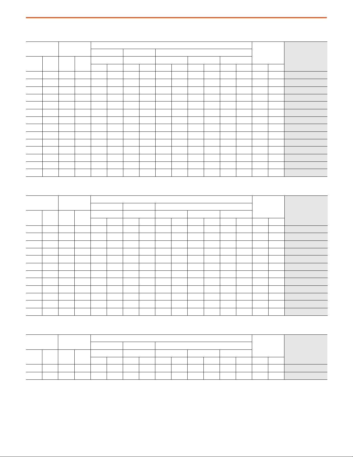
4.16 kV 50/60 Hz
PowerFlex 7000 Medium Voltage AC Drives Technical Data
Output Current
[A]
Cont. 1 Min. kW Hp
46 69 261 350 2100 82.7 1000 39.4 2318 91.3 325 12.8 2643 104.1 1955 4310
53 80 300 400 2100 82.7 1000 39.4 2318 91.3 325 12.8 2643 104.1 1955 4310
61 92 335 450 2100 82.7 1000 39.4 2318 91.3 325 12.8 2643 104.1 1955 4310
70 105 373 500 2100 82.7 1000 39.4 2318 91.3 325 12.8 2643 104.1 1955 4310
81 122 450 600 2100 82.7 1000 39.4 2318 91.3 325 12.8 2643 104.1 1955 4310 7000A-C DE_Y-RPTX
93 140 522 700 2100 82.7 1000 39.4 2318 91.3 325 12.8 2643 104.1 1955 4310
105 158 600 800 2100 82.7 1000 39.4 2318 91.3 325 12.8 2643 104.1 1955 4310
120 180 671 900 2100 82.7 1000 39.4 2318 91.3 325 12.8 2643 104.1 1955 4310 7000A-C DE_Y-RPTX
140 210 750 1000 2100 82.7 1000 39.4 2318 91.3 325 12.8 2643 104.1 1955 4310
160 240 933 1250 2100 82.7 1000 39.4 2318 91.3 325 12.8 2643 104.1 1955 4310
185 278 1082 1450 3000 118.1 1000 39.4 2318 91.3 325 12.8 2643 104.1 2841 6263 7000-C DE_D-RPTX
215 323 1120 1500 3000 118.1 1000 39.4 2318 91.3 325 12.8 2643 104.1 2841 6263
285 428 1680 2250 6634 261.2 1456 57.3 2334 91.9 340 13.4 2674 105.3 10910 24052
325 488 1865 2500 6634 261.2 1456 57.3 2334 91.9 340 13.4 2674 105.3 10910 24052 7000-G DE_D-RPTX
Typical Motor
Power Rating
Width Depth Height
W D H1 H2 H
mm in. mm in. mm in. mm in. mm in. kg lb
Approx Dimensions
Approx Weight
Base Catalog Number
7000A-C DE_Y-RPTX
7000A-C DE_Y-RPTX
7000A-C DE_Y-RPTX
7000A-C DE_Y-RPTX
7000A-C DE_Y-RPTX
7000A-C DE_Y-RPTX
7000A-C DE_Y-RPTX
7000A-C DE_Y-RPTX
7000-C DE_D-RPTX
7000-G DE_D-RPTX
6.6 kV 50/60 Hz
Output Current
[A]
Cont. 1 Min. kW Hp
40 60 400 500 2400 94.5 1000 39.4 2318 91.3 325 12.8 2643 104.1 2160 4762
46 69 410 550 2400 94.5 1000 39.4 2318 91.3 325 12.8 2643 104.1 2160 4762 7000A-C DJ_Y-RPTX
53 80 450 600 2400 94.5 1000 39.4 2318 91.3 325 12.8 2643 104.1 2160 4762
61 92 560 750 2400 94.5 1000 39.4 2318 91.3 325 12.8 2643 104.1 2160 4762
70 105 671 900 2400 94.5 1000 39.4 2318 91.3 325 12.8 2643 104.1 2160 4762 7000A-C DJ_Y-RPTX
81 122 750 1000 2400 94.5 1000 39.4 2318 91.3 325 12.8 2643 104.1 2160 4762
93 140 895 1200 2400 94.5 1000 39.4 2318 91.3 325 12.8 2643 104.1 2160 4762
105 158 933 1250 2400 94.5 1000 39.4 2318 91.3 325 12.8 2643 104.1 2160 4762 7000A-C DJ_Y-RPTX
120 180 1120 1500 3200 126.0 1000 39.4 2318 91.3 325 12.8 2643 104.1 2841 6263
140 210 1300 1750 3200 126.0 1000 39.4 2318 91.3 325 12.8 2643 104.1 2841 6263
160 240 1500 2000 3700 145.7 1000 39.4 2318 91.3 325 12.8 2643 104.1 4091 9019 7000-C DJ_Y-RPTX
185 278 1680 2250 3700 145.7 1000 39.4 2318 91.3 325 12.8 2643 104.1 4091 9019
Typical Motor
Power Rating
Width Depth Height
W D H1 H2 H
mm in. mm in. mm in. mm in. mm in. kg lb
Approx Dimensions
Approx Weight
Base Catalog Number
7000A-C DJ_Y-RPTX
7000A-C DJ_Y-RPTX
7000A-C DJ_Y-RPTX
7000A-C DJ_Y-RPTX
7000A-C DJ_Y-RPTX
7000-C DJ_Y-RPTX
7000-C DJ_Y-RPTX
7000-C DJ_Y-RPTX
6.6 kV 50 Hz
Output Current
[A]
Cont. 1 Min. kW Hp
215 323 2050 2750 6891 271.3 1456 57.3 2334 91.9 404 15.9 2738 107.8 8300 18298
250 375 2240 3000 6891 271.3 1456 57.3 2334 91.9 404 15.9 2738 107.8 8300 18298
Typical Motor
Power Rating
Width Depth Height
W D H1 H2 H
mm in. mm in. mm in. mm in. mm in. kg lb
Rockwell Automation Publication 7000-TD010A-EN-P - March 2021 27
Approx Dimensions
Approx Weight
Base Catalog Number
7000-C DJ_D-RPTX
7000-C DJ_D-RPTX

PowerFlex 7000 Medium Voltage AC Drives Technical Data
18 Pulse - Connection to Separate Transformer/Normal Duty
2.4 kV 60 Hz
Output Current
[A]
Cont. 1 Min. kW Hp
46 51 150 200 3100 122.0 1000 1000.0 2318 2318.0 325 325.0 2643 2643.0 2637 5814
53 58 168 225 3100 122.0 1000 1000.0 2318 2318.0 325 325.0 2643 2643.0 2637 5814
61 67 187 250 3100 122.0 1000 1000.0 2318 2318.0 325 325.0 2643 2643.0 2637 5814 7000-A DA_D-R18TX
70 77 225 300 3100 122.0 1000 1000.0 2318 2318.0 325 325.0 2643 2643.0 2637 5814
81 89 261 350 3100 122.0 1000 1000.0 2318 2318.0 325 325.0 2643 2643.0 2637 5814
93 102 300 400 3100 122.0 1000 1000.0 2318 2318.0 325 325.0 2643 2643.0 2637 5814 7000-A DA_D-R18TX
105 116 335 450 3100 122.0 1000 1000.0 2318 2318.0 325 325.0 2643 2643.0 2637 5814
120 132 373 500 3100 122.0 1000 1000.0 2318 2318.0 325 325.0 2643 2643.0 2637 5814
140 154 450 600 3100 122.0 1000 1000.0 2318 2318.0 325 325.0 2643 2643.0 2637 5814 7000-A DA_D-R18TX
160 176 522 700 3100 122.0 1000 1000.0 2318 2318.0 325 325.0 2643 2643.0 2637 5814
185 204 600 800 3100 122.0 1000 1000.0 2318 2318.0 325 325.0 2643 2643.0 2637 5814
215 237 670 900 3100 122.0 1000 1000.0 2318 2318.0 325 325.0 2643 2643.0 2637 5814 7000-A DA_D-R18TX
250 275 750 1000 3100 122.0 1000 1000.0 2318 2318.0 325 325.0 2643 2643.0 2637 5814
285 314 933 1250 3100 122.0 1000 1000.0 2318 2318.0 325 325.0 2643 2643.0 2637 5814
325 358 1120 1500 3100 122.0 1000 1000.0 2318 2318.0 325 325.0 2643 2643.0 2637 5814 7000-A DA_D-R18TX
375 413 1300 1750 3100 122.0 1000 1000.0 2318 2318.0 325 325.0 2643 2643.0 2637 5814
430 473 1500 2000 3100 122.0 1000 1000.0 2318 2318.0 325 325.0 2643 2643.0 2637 5814
Typical Motor
Power Rating
Width Depth Height
W D H1 H2 H
mm in. mm in. mm in. mm in. mm in. kg lb
Approx Dimensions
Approx Weight
Base Catalog Number
7000-A DA_D-R18TX
7000-A DA_D-R18TX
7000-A DA_D-R18TX
7000-A DA_D-R18TX
7000-A DA_D-R18TX
7000-A DA_D-R18TX
7000-A DA_D-R18TX
7000-A DA_D-R18TX
7000-A DA_D-R18TX
7000-A DA_D-R18TX
7000-A DA_D-R18TX
7000-A DA_D-R18TX
3.3 kV 50 Hz
Output Current
[A]
Cont. 1 Min. kW Hp
46 51 187 250 3300 129.9 1000 39.4 2318 91.3 325 12.8 2643 104.1 2955 6515
53 58 225 300 3300 129.9 1000 39.4 2318 91.3 325 12.8 2643 104.1 2955 6515
61 67 261 350 3300 129.9 1000 39.4 2318 91.3 325 12.8 2643 104.1 2955 6515 7000-A DC_D-R18TX
70 77 300 400 3300 129.9 1000 39.4 2318 91.3 325 12.8 2643 104.1 2955 6515
81 89 373 500 3300 129.9 1000 39.4 2318 91.3 325 12.8 2643 104.1 2955 6515
93 102 410 550 3300 129.9 1000 39.4 2318 91.3 325 12.8 2643 104.1 2955 6515 7000-A DC_D-R18TX
105 116 450 600 3300 129.9 1000 39.4 2318 91.3 325 12.8 2643 104.1 2955 6515
120 132 560 750 3300 129.9 1000 39.4 2318 91.3 325 12.8 2643 104.1 2955 6515
140 154 600 800 3300 129.9 1000 39.4 2318 91.3 325 12.8 2643 104.1 2955 6515 7000-A DC_D-R18TX
160 176 750 1000 3300 129.9 1000 39.4 2318 91.3 325 12.8 2643 104.1 2955 6515
185 204 820 1100 3300 129.9 1000 39.4 2318 91.3 325 12.8 2643 104.1 2955 6515
215 237 933 1250 3300 129.9 1000 39.4 2318 91.3 325 12.8 2643 104.1 2955 6515 7000-A DC_D-R18TX
250 275 1120 1500 3300 129.9 1000 39.4 2318 91.3 325 12.8 2643 104.1 2955 6515
285 314 1300 1750 3300 129.9 1000 39.4 2318 91.3 325 12.8 2643 104.1 2955 6515
325 358 1500 2000 3300 129.9 1000 39.4 2318 91.3 325 12.8 2643 104.1 2955 6515 7000-A DC_D-R18TX
375 413 1865 2500 3300 129.9 1000 39.4 2318 91.3 325 12.8 2643 104.1 2955 6515
430 473 2050 2750 3300 129.9 1000 39.4 2318 91.3 325 12.8 2643 104.1 2955 6515
Typical Motor
Power Rating
Width Depth Height
W D H1 H2 H
mm in. mm in. mm in. mm in. mm in. kg lb
Approx Dimensions
Approx Weight
Base Catalog Number
7000-A DC_D-R18TX
7000-A DC_D-R18TX
7000-A DC_D-R18TX
7000-A DC_D-R18TX
7000-A DC_D-R18TX
7000-A DC_D-R18TX
7000-A DC_D-R18TX
7000-A DC_D-R18TX
7000-A DC_D-R18TX
7000-A DC_D-R18TX
7000-A DC_D-R18TX
7000-A DC_D-R18TX
28 Rockwell Automation Publication 7000-TD010A-EN-P - March 2021
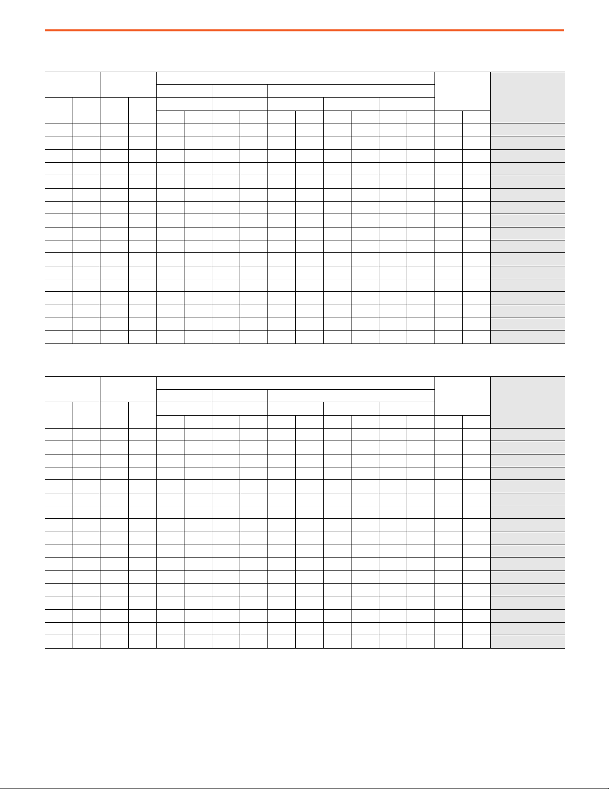
4.16 kV 60 Hz
PowerFlex 7000 Medium Voltage AC Drives Technical Data
Output Current
[A]
Cont. 1 Min. kW Hp
46 51 261 350 3100 122.0 1000 39.4 2318 91.3 325 12.8 2643 104.1 2637 5814
53 58 300 400 3100 122.0 1000 39.4 2318 91.3 325 12.8 2643 104.1 2637 5814
61 67 335 450 3100 122.0 1000 39.4 2318 91.3 325 12.8 2643 104.1 2637 5814
70 77 373 500 3100 122.0 1000 39.4 2318 91.3 325 12.8 2643 104.1 2637 5814
81 89 450 600 3100 122.0 1000 39.4 2318 91.3 325 12.8 2643 104.1 2637 5814 7000-A DE_D-R18TX
93 102 522 700 3100 122.0 1000 39.4 2318 91.3 325 12.8 2643 104.1 2637 5814
105 116 600 800 3100 122.0 1000 39.4 2318 91.3 325 12.8 2643 104.1 2637 5814
120 132 671 900 3100 122.0 1000 39.4 2318 91.3 325 12.8 2643 104.1 2637 5814 7000-A DE_D-R18TX
140 154 750 1000 3100 122.0 1000 39.4 2318 91.3 325 12.8 2643 104.1 2637 5814
160 176 933 1250 3100 122.0 1000 39.4 2318 91.3 325 12.8 2643 104.1 2637 5814
185 204 1082 1450 3100 122.0 1000 39.4 2318 91.3 325 12.8 2643 104.1 2637 5814 7000-A DE_D-R18TX
215 237 1120 1500 3100 122.0 1000 39.4 2318 91.3 325 12.8 2643 104.1 2637 5814
250 275 1500 2000 3100 122.0 1000 39.4 2318 91.3 325 12.8 2643 104.1 2637 5814
285 314 1680 2250 3100 122.0 1000 39.4 2318 91.3 325 12.8 2643 104.1 2637 5814 7000-A DE_D-R18TX
325 358 1865 2500 3100 122.0 1000 39.4 2318 91.3 325 12.8 2643 104.1 2637 5814
375 413 2240 3000 3300 129.9 1000 39.4 2318 91.3 325 12.8 2643 104.1 2955 6515
430 473 2600 3500 3300 129.9 1000 39.4 2318 91.3 325 12.8 2643 104.1 2955 6515 7000-A DE_D-R18TX
Typical Motor
Power Rating
Width Depth Height
W D H1 H2 H
mm in. mm in. mm in. mm in. mm in. kg lb
Approx Dimensions
Approx Weight
Base Catalog Number
7000-A DE_D-R18TX
7000-A DE_D-R18TX
7000-A DE_D-R18TX
7000-A DE_D-R18TX
7000-A DE_D-R18TX
7000-A DE_D-R18TX
7000-A DE_D-R18TX
7000-A DE_D-R18TX
7000-A DE_D-R18TX
7000-A DE_D-R18TX
7000-A DE_D-R18TX
7000-A DE_D-R18TX
4.16 kV 50 Hz
Output Current
[A]
Cont. 1 Min. kW Hp
46 51 261 350 3300 129.9 1000 39.4 2318 91.3 325 12.8 2643 104.1 2955 6515
53 58 300 400 3300 129.9 1000 39.4 2318 91.3 325 12.8 2643 104.1 2955 6515 7000-A DE_D-R18TX
61 67 335 450 3300 129.9 1000 39.4 2318 91.3 325 12.8 2643 104.1 2955 6515
70 77 373 500 3300 129.9 1000 39.4 2318 91.3 325 12.8 2643 104.1 2955 6515
81 89 450 600 3300 129.9 1000 39.4 2318 91.3 325 12.8 2643 104.1 2955 6515 7000-A DE_D-R18TX
93 102 522 700 3300 129.9 1000 39.4 2318 91.3 325 12.8 2643 104.1 2955 6515
105 116 600 800 3300 129.9 1000 39.4 2318 91.3 325 12.8 2643 104.1 2955 6515
120 132 671 900 3300 129.9 1000 39.4 2318 91.3 325 12.8 2643 104.1 2955 6515 7000-A DE_D-R18TX
140 154 750 1000 3300 129.9 1000 39.4 2318 91.3 325 12.8 2643 104.1 2955 6515
160 176 933 1250 3300 129.9 1000 39.4 2318 91.3 325 12.8 2643 104.1 2955 6515
185 204 1082 1450 3300 129.9 1000 39.4 2318 91.3 325 12.8 2643 104.1 2955 6515 7000-A DE_D-R18TX
215 237 1120 1500 3300 129.9 1000 39.4 2318 91.3 325 12.8 2643 104.1 2955 6515
250 275 1500 2000 3300 129.9 1000 39.4 2318 91.3 325 12.8 2643 104.1 2955 6515
285 314 1680 2250 3300 129.9 1000 39.4 2318 91.3 325 12.8 2643 104.1 2955 6515 7000-A DE_D-R18TX
325 358 1865 2500 3300 129.9 1000 39.4 2318 91.3 325 12.8 2643 104.1 2955 6515
375 413 2240 3000 3300 129.9 1000 39.4 2318 91.3 325 12.8 2643 104.1 2955 6515
430 473 2600 3500 4200 165.4 1000 39.4 2318 91.3 325 12.8 2643 104.1 4091 9019
Typical Motor
Power Rating
Width Depth Height
W D H1 H2 H
mm in. mm in. mm in. mm in. mm in. kg lb
Approx Dimensions
Approx Weight
Base Catalog Number
7000-A DE_D-R18TX
7000-A DE_D-R18TX
7000-A DE_D-R18TX
7000-A DE_D-R18TX
7000-A DE_D-R18TX
7000-A DE_D-R18TX
7000-A DE_D-R18TX
7000-A DE_D-R18TX
7000-A DE_D-R18TX
7000-A DE_D-R18TX
7000-A DE_D-R18TX
7000-A DE_D-R18TX
Rockwell Automation Publication 7000-TD010A-EN-P - March 2021 29
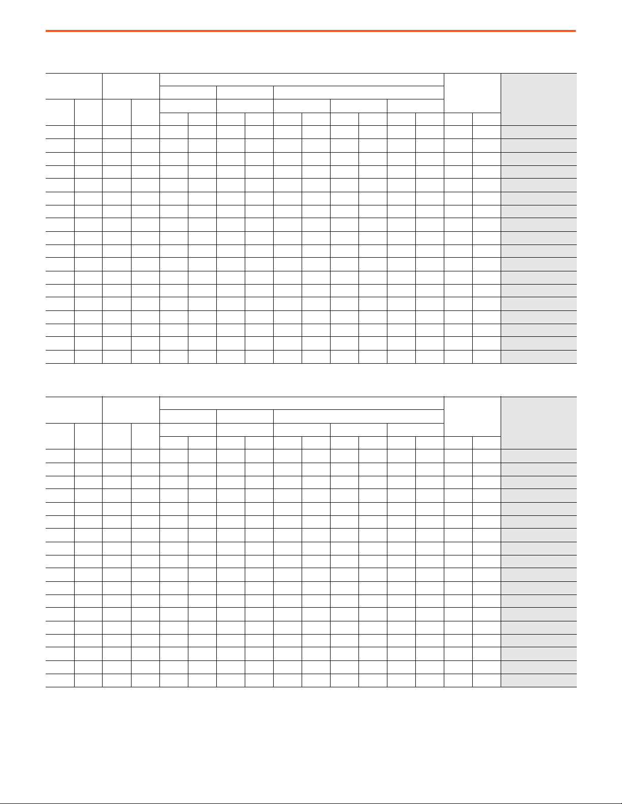
PowerFlex 7000 Medium Voltage AC Drives Technical Data
6.6 kV 60 Hz
Output Current
[A]
Cont. 1 Min. kW Hp
40 44 400 500 3300 129.9 1000 39.4 2318 91.3 325 12.8 2643 104.1 2955 6515
46 51 410 550 3300 129.9 1000 39.4 2318 91.3 325 12.8 2643 104.1 2955 6515
53 58 450 600 3300 129.9 1000 39.4 2318 91.3 325 12.8 2643 104.1 2955 6515
61 67 560 750 3300 129.9 1000 39.4 2318 91.3 325 12.8 2643 104.1 2955 6515
70 77 671 900 3300 129.9 1000 39.4 2318 91.3 325 12.8 2643 104.1 2955 6515 7000-A DJ_D-R18TX
81 89 750 1000 3300 129.9 1000 39.4 2318 91.3 325 12.8 2643 104.1 2955 6515
93 102 895 1200 3300 129.9 1000 39.4 2318 91.3 325 12.8 2643 104.1 2955 6515
105 116 933 1250 3300 129.9 1000 39.4 2318 91.3 325 12.8 2643 104.1 2955 6515 7000-A DJ_D-R18TX
120 132 1120 1500 3300 129.9 1000 39.4 2318 91.3 325 12.8 2643 104.1 2955 6515
140 154 1300 1750 3300 129.9 1000 39.4 2318 91.3 325 12.8 2643 104.1 2955 6515
160 176 1500 2000 3300 129.9 1000 39.4 2318 91.3 325 12.8 2643 104.1 2955 6515 7000-A DJ_D-R18TX
185 204 1680 2250 3300 129.9 1000 39.4 2318 91.3 325 12.8 2643 104.1 2955 6515
215 237 2050 2750 3300 129.9 1000 39.4 2318 91.3 325 12.8 2643 104.1 2955 6515
250 275 2240 3000 4200 165.4 1000 39.4 2318 91.3 325 12.8 2643 104.1 4091 9019 7000-A DJ_D-R18TX
285 314 2600 3500 4200 165.4 1000 39.4 2318 91.3 325 12.8 2643 104.1 4091 9019
325 358 3000 4000 4200 165.4 1000 39.4 2318 91.3 325 12.8 2643 104.1 4091 9019
375 413 3730 5000 4200 165.4 1000 39.4 2318 91.3 325 12.8 2643 104.1 4091 9019 7000-A DJ_D-R18TX
430 473 4100 5500 4200 165.4 1000 39.4 2318 91.3 325 12.8 2643 104.1 4091 9019
Typical Motor
Power Rating
Width Depth Height
W D H1 H2 H
mm in. mm in. mm in. mm in. mm in. kg lb
Approx Dimensions
Approx Weight
Base Catalog Number
7000-A DJ_D-R18TX
7000-A DJ_D-R18TX
7000-A DJ_D-R18TX
7000-A DJ_D-R18TX
7000-A DJ_D-R18TX
7000-A DJ_D-R18TX
7000-A DJ_D-R18TX
7000-A DJ_D-R18TX
7000-A DJ_D-R18TX
7000-A DJ_D-R18TX
7000-A DJ_D-R18TX
7000-A DJ_D-R18TX
7000-A DJ_D-R18TX
6.6 kV 50 Hz
Output Current
[A]
Cont. 1 Min. kW Hp
40 44 400 500 3300 129.9 1000 39.4 2318 91.3 325 12.8 2643 104.1 2955 6515
46 51 410 550 3300 129.9 1000 39.4 2318 91.3 325 12.8 2643 104.1 2955 6515
53 58 450 600 3300 129.9 1000 39.4 2318 91.3 325 12.8 2643 104.1 2955 6515
61 67 560 750 3300 129.9 1000 39.4 2318 91.3 325 12.8 2643 104.1 2955 6515 7000-A DJ_D-R18TX
70 77 671 900 3300 129.9 1000 39.4 2318 91.3 325 12.8 2643 104.1 2955 6515
81 89 750 1000 3300 129.9 1000 39.4 2318 91.3 325 12.8 2643 104.1 2955 6515
93 102 895 1200 3300 129.9 1000 39.4 2318 91.3 325 12.8 2643 104.1 2955 6515 7000-A DJ_D-R18TX
105 116 933 1250 3300 129.9 1000 39.4 2318 91.3 325 12.8 2643 104.1 2955 6515
120 132 1120 1500 3300 129.9 1000 39.4 2318 91.3 325 12.8 2643 104.1 2955 6515
140 154 1300 1750 3300 129.9 1000 39.4 2318 91.3 325 12.8 2643 104.1 2955 6515 7000-A DJ_D-R18TX
160 176 1500 2000 3300 129.9 1000 39.4 2318 91.3 325 12.8 2643 104.1 2955 6515
185 204 1680 2250 3300 129.9 1000 39.4 2318 91.3 325 12.8 2643 104.1 2955 6515
215 237 2050 2750 3300 129.9 1000 39.4 2318 91.3 325 12.8 2643 104.1 2955 6515 7000-A DJ_D-R18TX
250 275 2240 3000 4200 165.4 1000 39.4 2318 91.3 325 12.8 2643 104.1 4091 9019
285 314 2600 3500 4200 165.4 1000 39.4 2318 91.3 325 12.8 2643 104.1 4091 9019
325 358 3000 4000 4200 165.4 1000 39.4 2318 91.3 325 12.8 2643 104.1 4091 9019
375 413 3730 5000 4200 165.4 1000 39.4 2318 91.3 325 12.8 2643 104.1 4091 9019 7000-A DJ_D-R18TX
430 473 4100 5500 4200 165.4 1000 39.4 2318 91.3 325 12.8 2643 104.1 4091 9019
Typical Motor
Power Rating
Width Depth Height
W D H1 H2 H
mm in. mm in. mm in. mm in. mm in. kg lb
Approx Dimensions
Approx Weight
Base Catalog Number
7000-A DJ_D-R18TX
7000-A DJ_D-R18TX
7000-A DJ_D-R18TX
7000-A DJ_D-R18TX
7000-A DJ_D-R18TX
7000-A DJ_D-R18TX
7000-A DJ_D-R18TX
7000-A DJ_D-R18TX
7000-A DJ_D-R18TX
7000-A DJ_D-R18TX
7000-A DJ_D-R18TX
7000-A DJ_D-R18TX
7000-A DJ_D-R18TX
30 Rockwell Automation Publication 7000-TD010A-EN-P - March 2021
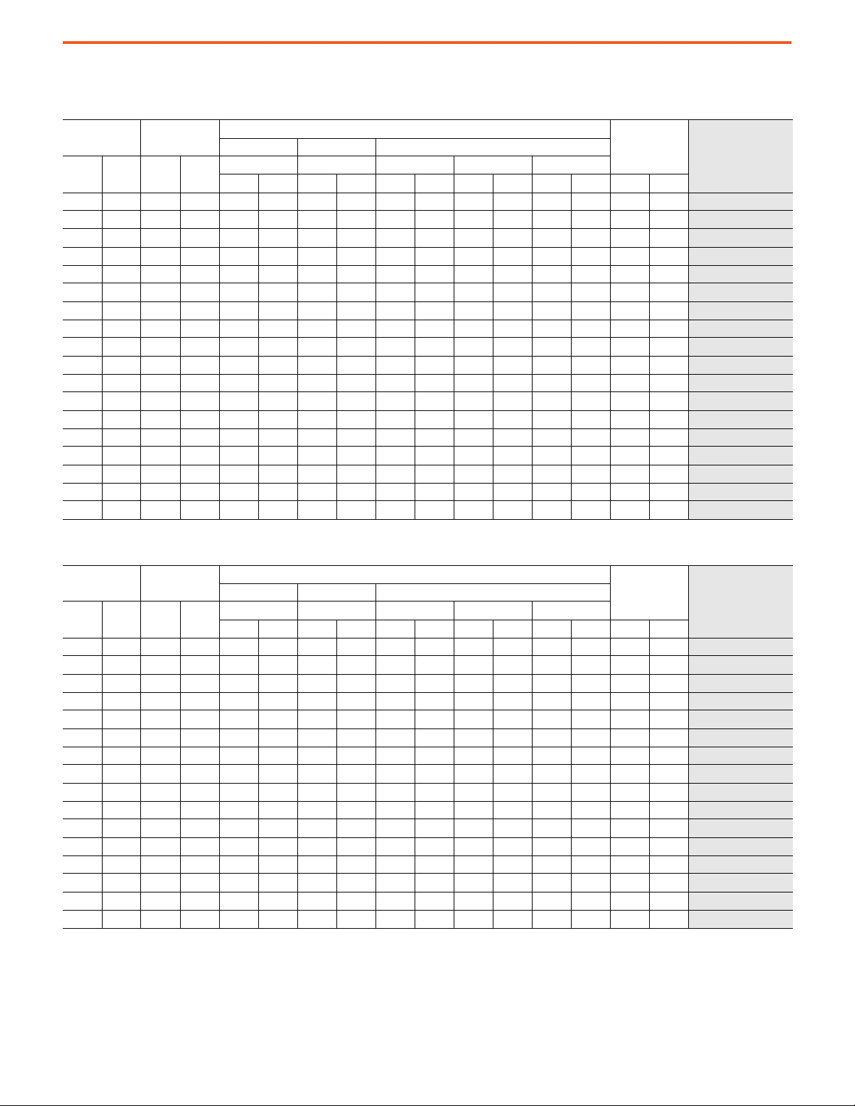
18 Pulse - Connection to Separate Transformer/Heavy Duty
2.4 kV 60 Hz
PowerFlex 7000 Medium Voltage AC Drives Technical Data
Output Current
[A]
Cont. 1 Min. kW Hp
40 44 400 500 3300 129.9 1000 39.4 2318 91.3 325 12.8 2643 104.1 2955 6515
46 69 150 200 3100 122.0 1000 39.4 2318 91.3 325 12.8 2643 104.1 2637 5814
53 80 168 225 3100 122.0 1000 39.4 2318 91.3 325 12.8 2643 104.1 2637 5814 7000-C DA_D-R18TX
61 92 187 250 3100 122.0 1000 39.4 2318 91.3 325 12.8 2643 104.1 2637 5814
70 105 225 300 3100 122.0 1000 39.4 2318 91.3 325 12.8 2643 104.1 2637 5814
81 122 261 350 3100 122.0 1000 39.4 2318 91.3 325 12.8 2643 104.1 2637 5814 7000-C DA_D-R18TX
93 140 300 400 3100 122.0 1000 39.4 2318 91.3 325 12.8 2643 104.1 2637 5814
105 158 335 450 3100 122.0 1000 39.4 2318 91.3 325 12.8 2643 104.1 2637 5814
120 180 373 500 3100 122.0 1000 39.4 2318 91.3 325 12.8 2643 104.1 2637 5814 7000-C DA_D-R18TX
140 210 450 600 3100 122.0 1000 39.4 2318 91.3 325 12.8 2643 104.1 2637 5814
160 240 522 700 3100 122.0 1000 39.4 2318 91.3 325 12.8 2643 104.1 2637 5814
185 278 600 800 3100 122.0 1000 39.4 2318 91.3 325 12.8 2643 104.1 2637 5814 7000-C DA_D-R18TX
215 323 670 900 3100 122.0 1000 39.4 2318 91.3 325 12.8 2643 104.1 2637 5814
250 375 750 1000 3100 122.0 1000 39.4 2318 91.3 325 12.8 2643 104.1 2637 5814
285 428 933 1250 3100 122.0 1000 39.4 2318 91.3 325 12.8 2643 104.1 2637 5814 7000-C DA_D-R18TX
325 488 1120 1500 3100 122.0 1000 39.4 2318 91.3 325 12.8 2643 104.1 2637 5814
375 563 1300 1750 3100 122.0 1000 39.4 2318 91.3 325 12.8 2643 104.1 2637 5814
430 645 1500 2000 3100 122.0 1000 39.4 2318 91.3 325 12.8 2643 104.1 2637 5814 7000-C DA_D-R18TX
Typical Motor
Power Rating
Width Depth Height
W D H1 H2 H
mm in. mm in. mm in. mm in. mm in. kg lb
Approx Dimensions
Approx Weight
Base Catalog Number
7000-C DA_D-R18TX
7000-C DA_D-R18TX
7000-C DA_D-R18TX
7000-C DA_D-R18TX
7000-C DA_D-R18TX
7000-C DA_D-R18TX
7000-C DA_D-R18TX
7000-C DA_D-R18TX
7000-C DA_D-R18TX
7000-C DA_D-R18TX
7000-C DA_D-R18TX
7000-C DA_D-R18TX
3.3 kV 50 Hz
Output Current
[A]
Cont. 1 Min. kW Hp
46 69 187 250 3300 129.9 1000 39.4 2318 91.3 325 12.8 2643 104.1 2955 6515
53 80 225 300 3300 129.9 1000 39.4 2318 91.3 325 12.8 2643 104.1 2955 6515 7000-C DC_D-R18TX
61 92 261 350 3300 129.9 1000 39.4 2318 91.3 325 12.8 2643 104.1 2955 6515
70 105 300 400 3300 129.9 1000 39.4 2318 91.3 325 12.8 2643 104.1 2955 6515
81 122 373 500 3300 129.9 1000 39.4 2318 91.3 325 12.8 2643 104.1 2955 6515 7000-C DC_D-R18TX
93 140 410 550 3300 129.9 1000 39.4 2318 91.3 325 12.8 2643 104.1 2955 6515
105 158 450 600 3300 129.9 1000 39.4 2318 91.3 325 12.8 2643 104.1 2955 6515
120 180 560 750 3300 129.9 1000 39.4 2318 91.3 325 12.8 2643 104.1 2955 6515 7000-C DC_D-R18TX
140 210 600 800 3300 129.9 1000 39.4 2318 91.3 325 12.8 2643 104.1 2955 6515
160 240 750 1000 3300 129.9 1000 39.4 2318 91.3 325 12.8 2643 104.1 2955 6515
185 278 820 1100 3300 129.9 1000 39.4 2318 91.3 325 12.8 2643 104.1 2955 6515 7000-C DC_D-R18TX
215 323 933 1250 3300 129.9 1000 39.4 2318 91.3 325 12.8 2643 104.1 2955 6515
250 375 1120 1500 3300 129.9 1000 39.4 2318 91.3 325 12.8 2643 104.1 2955 6515
285 428 1300 1750 3300 129.9 1000 39.4 2318 91.3 325 12.8 2643 104.1 2955 6515 7000-C DC_D-R18TX
325 488 1500 2000 3300 129.9 1000 39.4 2318 91.3 325 12.8 2643 104.1 2955 6515
375 563 1865 2500 3300 129.9 1000 39.4 2318 91.3 325 12.8 2643 104.1 2955 6515
Typical Motor
Power Rating
Width Depth Height
W D H1 H2 H
mm in. mm in. mm in. mm in. mm in. kg lb
Approx Dimensions
Approx Weight
Base Catalog Number
7000-C DC_D-R18TX
7000-C DC_D-R18TX
7000-C DC_D-R18TX
7000-C DC_D-R18TX
7000-C DC_D-R18TX
7000-C DC_D-R18TX
7000-C DC_D-R18TX
7000-C DC_D-R18TX
7000-C DC_D-R18TX
7000-C DC_D-R18TX
7000-C DC_D-R18TX
Rockwell Automation Publication 7000-TD010A-EN-P - March 2021 31

PowerFlex 7000 Medium Voltage AC Drives Technical Data
4.16 kV 60 Hz
Output Current
[A]
Cont. 1 Min. kW Hp
46 69 261 350 3100 122.0 1000 39.4 2318 91.3 325 12.8 2643 104.1 2637 5814
53 80 300 400 3100 122.0 1000 39.4 2318 91.3 325 12.8 2643 104.1 2637 5814
61 92 335 450 3100 122.0 1000 39.4 2318 91.3 325 12.8 2643 104.1 2637 5814
70 105 373 500 3100 122.0 1000 39.4 2318 91.3 325 12.8 2643 104.1 2637 5814
81 122 450 600 3100 122.0 1000 39.4 2318 91.3 325 12.8 2643 104.1 2637 5814 7000-C DE_D-R18TX
93 140 522 700 3100 122.0 1000 39.4 2318 91.3 325 12.8 2643 104.1 2637 5814
105 158 600 800 3100 122.0 1000 39.4 2318 91.3 325 12.8 2643 104.1 2637 5814
120 180 671 900 3100 122.0 1000 39.4 2318 91.3 325 12.8 2643 104.1 2637 5814 7000-C DE_D-R18TX
140 210 750 1000 3100 122.0 1000 39.4 2318 91.3 325 12.8 2643 104.1 2637 5814
160 240 933 1250 3100 122.0 1000 39.4 2318 91.3 325 12.8 2643 104.1 2637 5814
185 278 1082 1450 3100 122.0 1000 39.4 2318 91.3 325 12.8 2643 104.1 2637 5814 7000-C DE_D-R18TX
215 323 1120 1500 3100 122.0 1000 39.4 2318 91.3 325 12.8 2643 104.1 2637 5814
250 375 1500 2000 3100 122.0 1000 39.4 2318 91.3 325 12.8 2643 104.1 2637 5814
285 428 1680 2250 3100 122.0 1000 39.4 2318 91.3 325 12.8 2643 104.1 2637 5814 7000-C DE_D-R18TX
325 488 1865 2500 3100 122.0 1000 39.4 2318 91.3 325 12.8 2643 104.1 2637 5814
375 563 2240 3000 3300 129.9 1000 39.4 2318 91.3 325 12.8 2643 104.1 2955 6515
Typical Motor
Power Rating
Width Depth Height
W D H1 H2 H
mm in. mm in. mm in. mm in. mm in. kg lb
Approx Dimensions
Approx Weight
Base Catalog Number
7000-C DE_D-R18TX
7000-C DE_D-R18TX
7000-C DE_D-R18TX
7000-C DE_D-R18TX
7000-C DE_D-R18TX
7000-C DE_D-R18TX
7000-C DE_D-R18TX
7000-C DE_D-R18TX
7000-C DE_D-R18TX
7000-C DE_D-R18TX
7000-C DE_D-R18TX
7000-C DE_D-R18TX
4.16 kV 50 Hz
Output Current
[A]
Cont. 1 Min. kW Hp
46 69 261 350 3300 129.9 1000 39.4 2318 91.3 325 12.8 2643 104.1 2955 6515
53 80 300 400 3300 129.9 1000 39.4 2318 91.3 325 12.8 2643 104.1 2955 6515
61 92 335 450 3300 129.9 1000 39.4 2318 91.3 325 12.8 2643 104.1 2955 6515 7000-C DE_D-R18TX
70 105 373 500 3300 129.9 1000 39.4 2318 91.3 325 12.8 2643 104.1 2955 6515
81 122 450 600 3300 129.9 1000 39.4 2318 91.3 325 12.8 2643 104.1 2955 6515
93 140 522 700 3300 129.9 1000 39.4 2318 91.3 325 12.8 2643 104.1 2955 6515 7000-C DE_D-R18TX
105 158 600 800 3300 129.9 1000 39.4 2318 91.3 325 12.8 2643 104.1 2955 6515
120 180 671 900 3300 129.9 1000 39.4 2318 91.3 325 12.8 2643 104.1 2955 6515
140 210 750 1000 3300 129.9 1000 39.4 2318 91.3 325 12.8 2643 104.1 2955 6515 7000-C DE_D-R18TX
160 240 933 1250 3300 129.9 1000 39.4 2318 91.3 325 12.8 2643 104.1 2955 6515
185 278 1082 1450 3300 129.9 1000 39.4 2318 91.3 325 12.8 2643 104.1 2955 6515
215 323 1120 1500 3300 129.9 1000 39.4 2318 91.3 325 12.8 2643 104.1 2955 6515 7000-C DE_D-R18TX
250 375 1500 2000 3300 129.9 1000 39.4 2318 91.3 325 12.8 2643 104.1 2955 6515
285 428 1680 2250 3300 129.9 1000 39.4 2318 91.3 325 12.8 2643 104.1 2955 6515
325 488 1865 2500 3300 129.9 1000 39.4 2318 91.3 325 12.8 2643 104.1 2955 6515 7000-C DE_D-R18TX
375 563 2240 3000 3300 129.9 1000 39.4 2318 91.3 325 12.8 2643 104.1 2955 6515
Typical Motor
Power Rating
Width Depth Height
W D H1 H2 H
mm in. mm in. mm in. mm in. mm in. kg lb
Approx Dimensions
Approx Weight
Base Catalog Number
7000-C DE_D-R18TX
7000-C DE_D-R18TX
7000-C DE_D-R18TX
7000-C DE_D-R18TX
7000-C DE_D-R18TX
7000-C DE_D-R18TX
7000-C DE_D-R18TX
7000-C DE_D-R18TX
7000-C DE_D-R18TX
7000-C DE_D-R18TX
7000-C DE_D-R18TX
32 Rockwell Automation Publication 7000-TD010A-EN-P - March 2021

6.6 kV 50/60 Hz
PowerFlex 7000 Medium Voltage AC Drives Technical Data
Output Current
[A]
Cont. 1 Min. kW Hp
40 60 400 500 3300 129.9 1000 39.4 2318 91.3 325 12.8 2643 104.1 2955 6515
46 69 410 550 3300 129.9 1000 39.4 2318 91.3 325 12.8 2643 104.1 2955 6515
53 80 450 600 3300 129.9 1000 39.4 2318 91.3 325 12.8 2643 104.1 2955 6515
61 92 560 750 3300 129.9 1000 39.4 2318 91.3 325 12.8 2643 104.1 2955 6515
70 105 671 900 3300 129.9 1000 39.4 2318 91.3 325 12.8 2643 104.1 2955 6515 7000-C DJ_D-R18TX
81 122 750 1000 3300 129.9 1000 39.4 2318 91.3 325 12.8 2643 104.1 2955 6515
93 140 895 1200 3300 129.9 1000 39.4 2318 91.3 325 12.8 2643 104.1 2955 6515
105 158 933 1250 3300 129.9 1000 39.4 2318 91.3 325 12.8 2643 104.1 2955 6515 7000-C DJ_D-R18TX
120 180 1120 1500 3300 129.9 1000 39.4 2318 91.3 325 12.8 2643 104.1 2955 6515
140 210 1300 1750 3300 129.9 1000 39.4 2318 91.3 325 12.8 2643 104.1 2955 6515
160 240 1500 2000 3300 129.9 1000 39.4 2318 91.3 325 12.8 2643 104.1 2955 6515 7000-C DJ_D-R18TX
185 278 1680 2250 3300 129.9 1000 39.4 2318 91.3 325 12.8 2643 104.1 2955 6515
215 323 2050 2750 3300 129.9 1000 39.4 2318 91.3 325 12.8 2643 104.1 2955 6515
250 375 2240 3000 4200 165.4 1000 39.4 2318 91.3 325 12.8 2643 104.1 4091 9019 7000-C DJ_D-R18TX
285 428 2600 3500 4200 165.4 1000 39.4 2318 91.3 325 12.8 2643 104.1 4091 9019
325 488 3000 4000 4200 165.4 1000 39.4 2318 91.3 325 12.8 2643 104.1 4091 9019
Typical Motor
Power Rating
Width Depth Height
W D H1 H2 H
mm in. mm in. mm in. mm in. mm in. kg lb
Approx Dimensions
Approx Weight
Base Catalog Number
7000-C DJ_D-R18TX
7000-C DJ_D-R18TX
7000-C DJ_D-R18TX
7000-C DJ_D-R18TX
7000-C DJ_D-R18TX
7000-C DJ_D-R18TX
7000-C DJ_D-R18TX
7000-C DJ_D-R18TX
7000-C DJ_D-R18TX
7000-C DJ_D-R18TX
7000-C DJ_D-R18TX
7000-C DJ_D-R18TX
Rockwell Automation Publication 7000-TD010A-EN-P - March 2021 33

PowerFlex 7000 Medium Voltage AC Drives Technical Data
PowerFlex 7000 Liquid-cooled Drives
Direct-to-Drive/Normal Duty
4.16 kV 60 Hz
Output Current
[A]
Cont. 1 Min. kW Hp
375 413 2240 3000 6200 244.1 1000 39.4 2318 91.3 204 8.0 2522 99.3 8164 17999
430 473 2600 3500 6200 244.1 1000 39.4 2318 91.3 204 8.0 2522 99.3 8164 17999 7000L-A DE_D-RPDTD
495 545 3000 4000 6200 244.1 1000 39.4 2318 91.3 204 8.0 2522 99.3 8164 17999
575 633 3360 4500 6800 267.7 1000 39.4 2318 91.3 204 8.0 2522 99.3 8890 19599
625 688 3730 5000 6800 267.7 1000 39.4 2318 91.3 204 8.0 2522 99.3 8890 19599 7000L-A DE_D-RPDTD
Typical Motor
Power Rating
Width Depth Height
W D H1 H2 H
mm in. mm in. mm in. mm in. mm in. kg lb
Approx Dimensions
Approx Weight
Base Catalog Number
7000L-A DE_D-RPDTD
7000L-A DE_D-RPDTD
7000L-A DE_D-RPDTD
4.16 kV 50 Hz
Output Current
[A]
Cont. 1 Min. kW Hp
375 413 2240 3000 6200 6200.0 1000 6200.0 2318 6200.0 204 6200.0 2522 6200.0 8164 17999
430 473 2600 3500 6200 6200.0 1000 6200.0 2318 6200.0 204 6200.0 2522 6200.0 8164 17999 7000L-A DE_D-RPDTD
495 545 3000 4000 6400 6200.0 1000 6200.0 2318 6200.0 204 6200.0 2522 6200.0 8618 18999
575 633 3360 4500 6800 6800.0 1000 6800.0 2318 6800.0 204 6800.0 2522 6800.0 8890 19599
Typical Motor
Power Rating
Width Depth Height
W D H1 H2 H
mm in. mm in. mm in. mm in. mm in. kg lb
Approx Dimensions
Approx Weight
Base Catalog Number
7000L-A DE_D-RPDTD
7000L-A DE_D-RPDTD
7000L-A DE_D-RPDTD
6.6 kV 60 Hz
Output Current
[A]
Cont. 1 Min. kW Hp
325 358 3000 4000 6700 263.8 1000 39.4 2318 91.3 204 8.0 2522 99.3 9139 20148
375 413 3730 5000 6700 263.8 1000 39.4 2318 91.3 204 8.0 2522 99.3 9139 20148
430 473 4100 5500 7500 295.3 1051 41.4 2318 91.3 204 8.0 2522 99.3 10936 24110 7000L-A DJ_D-RPDTD
495 545 4850 6500 7700 303.1 1051 41.4 2318 91.3 204 8.0 2522 99.3 11699 25792
575 633 5595 7500 8100 318.9 1051 41.4 2318 91.3 204 8.0 2522 99.3 12828 28281
Typical Motor
Power Rating
Width Depth Height
W D H1 H2 H
mm in. mm in. mm in. mm in. mm in. kg lb
Approx Dimensions
Approx Weight
Base Catalog Number
7000L-A DJ_D-RPDTD
7000L-A DJ_D-RPDTD
7000L-A DJ_D-RPDTD
7000L-A DJ_D-RPDTD
6.6kV 50Hz
Output Current
[A]
Cont. 1 Min. kW Hp
325 358 3000 4000 6700 263.8 1000 39.4 2318 91.3 204 8.0 2522 99.3 9139 20148
375 413 3730 5000 6700 263.8 1000 39.4 2318 91.3 204 8.0 2522 99.3 9139 20148
430 473 4100 5500 7500 295.3 1051 41.4 2318 91.3 204 8.0 2522 99.3 10936 24110 7000L-A DJ_D-RPDTD
495 545 4850 6500 7700 303.1 1051 41.4 2318 91.3 204 8.0 2522 99.3 11699 25792
575 633 5595 7500 8100 318.9 1051 41.4 2318 91.3 204 8.0 2522 99.3 12828 28281
34 Rockwell Automation Publication 7000-TD010A-EN-P - March 2021
Typical Motor
Power Rating
Width Depth Height
W D H1 H2 H
mm in. mm in. mm in. mm in. mm in. kg lb
Approx Dimensions
Approx Weight
Base Catalog Number
7000L-A DJ_D-RPDTD
7000L-A DJ_D-RPDTD
7000L-A DJ_D-RPDTD
7000L-A DJ_D-RPDTD

18 Pulse - Connection to Separate Transformer/Normal Duty
4.16 kV 60 Hz
PowerFlex 7000 Medium Voltage AC Drives Technical Data
Output Current
[A]
Cont. 1 Min. kW Hp
375 413 2240 3000 5100 200.8 1000 39.4 2318 91.3 204 8.0 2522 99.3 6363 14028
430 473 2600 3500 5100 200.8 1000 39.4 2318 91.3 204 8.0 2522 99.3 6363 14028
495 545 3000 4000 5100 200.8 1000 39.4 2318 91.3 204 8.0 2522 99.3 6363 14028 7000L-A DE_D-RP18TX
575 633 3360 4500 5100 200.8 1000 39.4 2318 91.3 204 8.0 2522 99.3 6363 14028
625 688 3730 5000 5100 200.8 1000 39.4 2318 91.3 204 8.0 2522 99.3 6363 14028
657 723 3900 5250 5100 200.8 1000 39.4 2318 91.3 204 8.0 2522 99.3 6363 14028 7000L-A DE_D-RP18TX
Typical Motor
Power Rating
Width Depth Height
W D H1 H2 H
mm in. mm in. mm in. mm in. mm in. kg lb
Approx Dimensions
Approx Weight
Base Catalog Number
7000L-A DE_D-RP18TX
7000L-A DE_D-RP18TX
7000L-A DE_D-RP18TX
7000L-A DE_D-RP18TX
4.16 kV 50 Hz
Output Current
[A]
Cont. 1 Min. kW Hp
375 413 2240 3000 5100 200.8 1000 39.4 2318 91.3 204 8.0 2522 99.3 6363 14028
430 473 2600 3500 5100 200.8 1000 39.4 2318 91.3 204 8.0 2522 99.3 6363 14028 7000L-A DE_D-RP18TX
495 545 3000 4000 5100 200.8 1000 39.4 2318 91.3 204 8.0 2522 99.3 6363 14028
575 633 3360 4500 5100 200.8 1000 39.4 2318 91.3 204 8.0 2522 99.3 6363 14028
625 688 3730 5000 5100 200.8 1000 39.4 2318 91.3 204 8.0 2522 99.3 6363 14028 7000L-A DE_D-RP18TX
657 723 3900 5250 5100 200.8 1000 39.4 2318 91.3 204 8.0 2522 99.3 6363 14028
Typical Motor
Power Rating
Width Depth Height
W D H1 H2 H
mm in. mm in. mm in. mm in. mm in. kg lb
Approx Dimensions
Approx Weight
Base Catalog Number
7000L-A DE_D-RP18TX
7000L-A DE_D-RP18TX
7000L-A DE_D-RP18TX
7000L-A DE_D-RP18TX
6.6 kV 60 Hz
Output Current
[A]
Cont. 1 Min. kW Hp
375 413 3730 5000 5100 200.8 1000 39.4 2318 91.3 204 8.0 2522 99.3 6363 14028
430 473 4100 5500 5100 200.8 1000 39.4 2318 91.3 204 8.0 2522 99.3 6363 14028
495 545 4850 6500 5100 200.8 1000 39.4 2318 91.3 204 8.0 2522 99.3 6363 14028
575 633 5595 7000 5100 200.8 1000 39.4 2318 91.3 204 8.0 2522 99.3 6363 14028 7000L-A DJ_D-RP18TX
625 688 6000 8000 5500 216.5 1000 39.4 2318 91.3 204 8.0 2522 99.3 6818 15031
657 723 6340 8500 5500 216.5 1000 39.4 2318 91.3 204 8.0 2522 99.3 6818 15031
Typical Motor
Power Rating
Width Depth Height
W D H1 H2 H
mm in. mm in. mm in. mm in. mm in. kg lb
Approx Dimensions
Approx Weight
Base Catalog Number
7000L-A DJ_D-RP18TX
7000L-A DJ_D-RP18TX
7000L-A DJ_D-RP18TX
7000L-A DJ_D-RP18TX
7000L-A DJ_D-RP18TX
6.6 kV 50 Hz
Output Current
[A]
Cont. 1 Min. kW Hp
375 413 3730 5000 5100 200.8 1000 39.4 2318 91.3 204 8.0 2522 99.3 6363 14028
430 473 4100 5500 5100 200.8 1000 39.4 2318 91.3 204 8.0 2522 99.3 6363 14028
495 545 4850 6500 5100 200.8 1000 39.4 2318 91.3 204 8.0 2522 99.3 6363 14028
575 633 5595 7000 5100 200.8 1000 39.4 2318 91.3 204 8.0 2522 99.3 6363 14028 7000L-A DJ_D-RP18TX
625 688 6000 8000 5500 216.5 1000 39.4 2318 91.3 204 8.0 2522 99.3 6818 15031
657 723 6340 8500 5500 216.5 1000 39.4 2318 91.3 204 8.0 2522 99.3 6818 15031
Typical Motor
Power Rating
Width Depth Height
W D H1 H2 H
mm in. mm in. mm in. mm in. mm in. kg lb
Approx Dimensions
Approx Weight
Base Catalog Number
7000L-A DJ_D-RP18TX
7000L-A DJ_D-RP18TX
7000L-A DJ_D-RP18TX
7000L-A DJ_D-RP18TX
7000L-A DJ_D-RP18TX
Rockwell Automation Publication 7000-TD010A-EN-P - March 2021 35

PowerFlex 7000 Medium Voltage AC Drives Technical Data
18 Pulse - Connection to Separate Transformer/Heavy Duty
4.16 kV 60 Hz
Output Current
[A]
Cont. 1 Min. kW Hp
375 563 2240 3000 5100 200.8 1000 39.4 2318 91.3 204 8.0 2522 99.3 6363 14028
430 645 2600 3500 5100 200.8 1000 39.4 2318 91.3 204 8.0 2522 99.3 6363 14028
Typical Motor
Power Rating
Width Depth Height
W D H1 H2 H
mm in. mm in. mm in. mm in. mm in. kg lb
Approx Dimensions
Approx Weight
4.16 kV 50 Hz
Output Current
[A]
Cont. 1 Min. kW Hp
375 563 2240 3000 5100 200.8 1000 39.4 2318 91.3 204 8.0 2522 99.3 6363 14028
430 645 2600 3500 5100 200.8 1000 39.4 2318 91.3 204 8.0 2522 99.3 6363 14028
Typical Motor
Power Rating
Width Depth Height
W D H1 H2 H
mm in. mm in. mm in. mm in. mm in. kg lb
Approx Dimensions
Approx Weight
6.6 kV 50/60 Hz
Output Amps
Cont. 1 Min. kW Hp
375 563 3730 5000 5100 200.8 1000 39.4 2318 91.3 204 8.0 2522 99.3 6363 14028
430 645 4100 5500 5100 200.8 1000 39.4 2318 91.3 204 8.0 2522 99.3 6363 14028
Typical Motor
Power Rating
Width Depth Height
W D H1 H2 H
mm in. mm in. mm in. mm in. mm in. kg lb
Approx Dimensions
Approx Weight
Base Catalog Number
7000L-C DE_D-RP18TX
7000L-C DE_D-RP18TX
Base Catalog Number
7000L-C DE_D-RP18TX
7000L-C DE_D-RP18TX
Base Catalog Number
7000L-C DJ_D-RP18TX
7000L-C DJ_D-RP18TX
36 Rockwell Automation Publication 7000-TD010A-EN-P - March 2021

PowerFlex 7000 Medium Voltage AC Drives Technical Data
Cable Considerations
A variety of cable types are acceptable for drive installations. Follow applicable local codes to determine power and motor cable conductor
size and quantity. For detailed information on cable installation, see the installation instructions for your drive, which are listed in the
Additional Resources
Power Wiring Considerations
The following recommended field power cabling insulation levels help to enable trouble-free startup and operation. Increase the cable
insulation level over that which would be supplied for an across-the-line application with the same rated line-to-line voltage.
Shielded or unshielded cable may be used based on the criteria considered by the distribution system designer and local standards.
However, NEC requires shielded cable for installations above 2 kV.
These tables provide cable insulation requirements for the PowerFlex 7000 drives.
a
Cable Insulation Requirements for AFE and 18-pulse Drives with Isolation Transformer
System Voltage (V
2400 ≥4.1 ≥2.2
3000 ≥5.12 ≥2.75
3300 ≥5.63 ≥3.0
4160 ≥7.1 ≥3.8
6000 ≥10.8 ≥5.5
6300 ≥11.4 ≥5.8
6600 ≥11.8 ≥6.0
on page 55.
)
rms
Cable Insulation Rating (kV)
(Maximum Peak Line-to-Ground)
Line Side Machine Side
Cable Insulation Requirements for Direct-to-Drive Technology
Cable Insulation Rating (kV)
System Voltage (V
2400 ≥2.2 ≥2.2
3000 ≥2.75 ≥2.75
3300 ≥3.0 ≥3.0
4160 ≥3.8 ≥3.8
6000 ≥5.5 ≥5.5
6300 ≥5.8 ≥5.8
6600 ≥6.0 ≥6.0
rms
)
(Maximum Peak Line-to-Ground)
Line Side Machine Side
Rockwell Automation Publication 7000-TD010A-EN-P - March 2021 37

PowerFlex 7000 Medium Voltage AC Drives Technical Data
Motor Cable Sizing
Voltage drop in motor leads may adversely affect motor starting and running performance. Installation and application requirements may
dictate that larger wire sizes than indicated in national and local electrical codes are used.
You must select wire sizes individually, observing all applicable safety and national and local electrical codes. The minimum permissible wire
size does not necessarily result in the best operating economy. The minimum recommended size for the wires between the drive and the
motor is the same as that used if a main voltage source connection to the motor was used. The distance between the drive and motor can
affect the size of the conductors used.
Control Signal Wiring Considerations
Use shielded cables for all analog and digital control cables. Steel conduit or a cable tray can be used for all PowerFlex 7000 drive power or
control wiring; however, use only steel conduit for all signal wiring.
Steel conduit is required for all control and signal circuits when the drive is installed in European Union countries.
General Wire Categories
Identifies general wire categories that will be encountered when installing the PowerFlex drive.
• Each category has an associated wire group number that is used in the following sections to identify the wire to be used.
• Application and signal examples along with the recommended type of cable for each group are provided.
• A matrix providing the recommended minimum spacing between different wire groups run in the same tray or separate conduit is
also provided.
• You must select the wire sizes individually, observing all applicable safety and CEC or IEC/NEC regulations.
• The minimum permissible wire size does not necessarily result in the best operating economy.
• The minimum recommended size for the wires between the drive and the motor is the same as that used if a main voltage source
connection to the motor was used.
• The distance between the drive and motor may affect the size of the conductors used.
38 Rockwell Automation Publication 7000-TD010A-EN-P - March 2021
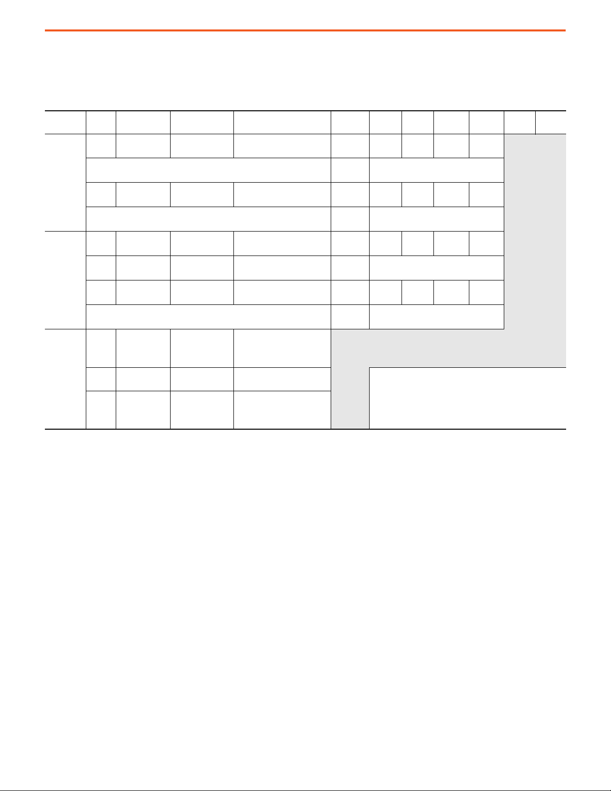
For Tray: Recommended spacing between different wire groups in the same tray.
For Conduit: Recommended spacing for wire groups in separate conduit – mm (in.).
Wire Group Numbers
PowerFlex 7000 Medium Voltage AC Drives Technical Data
Wire
Category
Power
Control
Signal
(1) 18 AWG, twisted pair, shielded.
(2) 18 AWG, 3 conductor, shielded.
(3) 18 AWG, twisted pair, shielded.
(4) 24 AWG, twisted pair, shielded.
Wire
Group
1
2
3
4
5
6
Application Signal Example Recommended Cables
AC Power
(>600V AC)
AC Power
(TO 600V AC)
115V AC or
115V DC Logic
24V AC or
24V DC Logic
Analog Signals
DC Supplies
(Low Speed)
(High Speed)
115V AC
Power
Digital
Digital
2.3 kV, 3Ø AC Lines
480V, 3Ø
Relay Logic PLC I/O
Power Supplies
Instruments
PLC I/O
5…24V DC
Supplies
Power Supplies TTL
Logic Level
Pulse Train Input
Tachometer PLC
Communications
Per IEC/NEC Local Codes and
Application Requirements
Per IEC/NEC Local Codes and
Application Requirements
Per IEC/NEC Local Codes and
Application Requirements
Per IEC/NEC Local Codes and
Application Requirements
Belden 8760
Belden 8770
Belden 9460
Belden 8760
Belden 9460
Belden 9463
(1)
(2)
(3)
(1)
(3)
(4)
Wire
Group
In Tray
Between
Conduit
In Tray
Between
Conduit
In Tray
Between
Conduit
In Tray
Between
Conduit
Power 1 Power 2 Control 3 Control 4 Signal 5 Signal 6
228.6
(9.00)
228.6
(9.00)
228.6
(9.00)
228.6
(9.00)
• All signal wiring must be run in separate steel conduit. A wire
tray is not suitable.
• The minimum spacing between conduits containing different
wire groups is 76.2 mm (3 in.).
228.6
(9.00)
76.2 (3.00) Between Conduit
228.6
(9.00)
76.2 (3.00) Between Conduit
152.4
(6.00)
76.2 (3.00) Between Conduit
152.4
(6.00)
76.2 (3.00) Between Conduit
228.6
(9.00)
152.4
(6.00)
228.6
(9.00)
152.4
(6.00)
228.6
(9.00)
152.4
(6.00)
152.4
(6.00)
228.6
(9.00)
Note the following when considering cable selection:
• Steel conduit or cable tray may be used for all PowerFlex 7000 drive power or control wiring, and steel conduit is required for all
PowerFlex 7000 drive signal wiring. All input and output power wiring, control wiring or conduit should be brought through the drive
conduit entry holes of the enclosure. Use appropriate connectors to maintain the environmental rating of the enclosure. The steel
conduit is REQUIRED for all control and signal circuits, when the drive is installed in European Union countries. The connection of the
conduit to the enclosure shall be on full 360° and the ground bond at the junction shall be less than 0.1 Ω. In EU countries this is a
usual practice to install the control and signal wiring.
• Spacing between wire groups is the recommended minimum for parallel runs of 61 m (200 ft) or less.
• The customer is responsible for the grounding of shields. On drives shipped after November 28/02, the shields are removed from the
drive boards. On drives shipped prior to November 28/02, all shields are connected at the drive end and these connections must be
removed before grounding the shield at the customer end of the cable. Shields for cables from one enclosure to another must be
grounded only at the source end cabinet. If splicing of shielded cables is required, the shield must remain continuous and insulated
from ground.
• AC and DC circuits must be run in separate conduits or trays.
• Voltage drop in motor leads may adversely affect motor starting and running performance. Installation and application requirements
may dictate that larger wire sizes than indicated in IEC/NEC guidelines are used.
Rockwell Automation Publication 7000-TD010A-EN-P - March 2021 39

PowerFlex 7000 Medium Voltage AC Drives Technical Data
Line and Load Cable Sizes
This data is informative only; do not base final design criteria solely on this data. Follow national and local installation codes, industry
standard practices, and cable manufacturer recommendations. Because cabling methods can vary widely, maximum cables sizes do not
account for the size of the conduit hub.
PowerFlex ‘A’ Frame
Maximum Line Cable Size
Product Input (Line Side)
).
Space for
Stress Cones
[in. (mm)]
20.0 (508)
20.0 (508)
20.0 (508)
20.0 (508)
20.0 (508)
(9)
(9)
(9)
(9)
(9)
Voltage/Frequency/
Rectifier
Drive
Rating [A]
2400V/60 Hz/RPDTD 46…140
2400V/60 Hz/RPDTD 46…140
3300V/50 Hz/RPDTD 46…140
3300V/50 Hz/RPDTD 46…140
4160V/50 Hz/RPDTD 46…140
4160V/50 Hz/RPDTD 46…140
4160V/60 Hz/RPDTD 46…140
4160V/60 Hz/RPDTD 46…140
6600V/50 Hz/RPDTD 40…93
6600V/50 Hz/RPDTD 40…93
Drive
Structure
Code
71.9
71.13, 71.18
71.9
71.13, 71.18
71.9
71.13, 71.18
71.9
71.13, 71.18
71.10
71.14, 71.19
2400V/60 Hz/RPTX 46…160 71.7
3300V/50 Hz/RPTX 46…160 71.7
4160/50 Hz/RPTX 46…160 71.7
4160/60 Hz/RPTX 46…160 71.7
6600/50 Hz/RPTX 40…105 71.8
Drive Enclosure
Opening [in. (mm)]
(7)
4.00 x 4.00 (102 x 102) One #4/0/phase (5 kV or 8 kV) One 107 mm² /phase (5 kV or 8 kV) 18.8 (478)
(8)
4.00 x 4.00 (102 x 102) One #4/0/phase (5 kV or 8 kV) One 107 mm²/phase (5 kV or 8 kV) 17.1 (435)
(7)
4.00 x 4.00 (102 x 102) One #4/0/phase (5 kV or 8 kV) One 107 mm²/phase (5 kV or 8 kV) 18.8 (478)
(8)
4.00 x 4.00 (102 x 102) One #4/0/phase (5 kV or 8 kV) One 107 mm²/phase (5 kV or 8 kV) 17.1 (435)
(7)
4.00 x 4.00 (102 x 102) One #4/0/phase (5 kV or 8 kV) One 107 mm²/phase (5 kV or 8 kV) 18.8 (478)
(8)
4.00 x 4.00 (102 x 102) One #4/0/phase (5 kV or 8 kV) One 107 mm²/phase (5 kV or 8 kV) 17.1 (435)
(7)
4.00 x 4.00 (102 x 102) One #4/0/phase (5 kV or 8 kV) One 107 mm²/phase (5 kV or 8 kV) 18-3/8 (467)
(8)
4.00 x 4.00 (102 x 102) One #4/0/phase (5 kV or 8 kV) One 107 mm²/phase (5 kV or 8 kV) 17.1 (435)
(7)
4.00 x 4.00 (102 x 102) One #4/0/phase (8 kV or 15 kV) One 107 mm²/phase (5 kV or 8 kV) 18.8 (478)
(8)
4.00 x 4.00 (102 x 102) One 350 MCM/phase (8 kV or 15 kV) One 177 mm²/phase (5 kV or 8 kV) 17.1 (435)
4.00 x 8.00 (102 x 204)
4.00 x 8.00 (102 x 204)
4.00 x 8.00 (102 x 204)
4.00 x 8.00 (102 x 204)
4.00 x 8.00 (102 x 204)
No. and Max. Size of Incoming
(1)
Cables (NEMA)
(1)
One 350 MCM/phase (8 kV or 15 kV) One 177 mm²/phase (5 kV or 8 kV) 33.8 (860)
(1)
One 350 MCM/phase (8 kV or 15 kV) One 177 mm²/phase (8 kV or 15 kV) 33.8 (860)
(1)
One 350 MCM/phase (8 kV or 15 kV) One 177 mm²/phase (8 kV or 15 kV) 33.8 (860)
(1)
One 350 MCM/phase (8 kV or 15 kV) One 177 mm²/phase (8 kV or 15 kV) 33.8 (860)
(1)
One 350 MCM/phase (15 kV) One 177 mm²/phase (15 kV) 33.8 (860)
(2)(3)(4)(5)(6)
No. and Max. Size of Incoming
Cables (IEC)
(2)(3)(4)(5)(6)
2400V/60 Hz/RPTXI 46…160 71.3 4.00 x 4.00 (102 x 102) One 350 MCM/phase (8 kV or 15 kV) One 177 mm²/phase (5 kV or 8 kV)
3300V/50 Hz/RPTXI 46…160 71.3 4.00 x 4.00 (102 x 102) One 350 MCM/phase (8 kV or 15 kV) One 177 mm²/phase (5 kV or 8 kV)
4160V/50 Hz/RPTXI 46…140 71.3 4.00 x 4.00 (102 x 102) One 350 MCM/phase (8 kV or 15 kV) One 177 mm²/phase (5 kV or 8 kV)
4160V/60 Hz/RPTXI 46…160 71.3 4.00 x 4.00 (102 x 102) One 350 MCM/phase (8 kV or 15 kV) One 177 mm²/phase (5 kV or 8 kV)
6600V/50 Hz/RPTXI 40…105 71.6, 71.15 4.00 x 4.00 (102 x 102) One #4/0/phase (8 kV or 15 kV) One 177 mm²/phase (8 kV or 15 kV)
(1) Some ‘A’ frame drives have one enclosure opening for both line and load cables. Most ‘A’ frame drives have separate provisions for line and load cable openings. All cabling capacities that
are shown in this table are “worst case” conditions when both line and load cables enter and exit in the same direction.
(2) Cable sizes are based on overall dimensions of compact-stranded three-conductor shielded cable (common for industrial-cable tray installations). Maximum sizes stated accounts for
minimum rated cable insulation requirements. The next higher-rated cable (8 kV is not commercially available in many areas of the world. Rockwell Automation provides an 8 kV (minimum
rating) and a 15 kV rating, when applicable. Enclosure openings accommodate the thicker insulation on the higher-rated cable. IEC ratings show the equivalent to the NEMA sizes. The exact
2
size that is shown is not commercially available in many cases; use the next smaller standard size.
cable mm
(3) Minimum cable bend radius recommendations vary by national codes, cable type, and cable size. Consult local codes for guidelines and requirements. General relationship of cable diameter
to bend radius is typically between 7…12x. For example, if the cable diameter is 1 in. [2.54 cm] the minimum bend radius could range between 7…12 in. [18.8…30.48 cm]).
(4) For minimum requirements for cable insulation, see the user manual for your frame. Stated voltages are peak line-to-ground. Some cable manufacturers rate cabling based on RMS line-to-
line.
(5) Ground lug capabilities: two mechanical range lugs for ground cable connections. Mechanical range lugs can accommodate cable size #6…250MCM (13.3...127 mm
(6) As methods for cabling can vary, the maximum cable sizes that are shown do not account for the size of the conduit hub. Verify size of conduit hubs against the “Drive enclosure openings”
shown.
(7) With starter.
(8) Without starter.
(9) Cable enters termination point horizontally in this case; therefore orient space for the stress cones horizontally also.
2
40 Rockwell Automation Publication 7000-TD010A-EN-P - March 2021

PowerFlex 7000 Medium Voltage AC Drives Technical Data
PowerFlex ‘A’ Frame
Maximum Load Cable Size
Product Output (Motor Side)
Voltage/Frequency/
Rectifier
Drive
Rating (A)
2400V/60 Hz/RPDTD 46…140
2400V/60 Hz/RPDTD 46…140
3300V/50 Hz/RPDTD 46…140
3300V/50 Hz/RPDTD 46…140
4160V/50 Hz/RPDTD 46…140
4160V/50 Hz/RPDTD 46…140
4160V/60 Hz/RPDTD 46…140
4160V/60 Hz/RPDTD 46…140
6600V/50 Hz/RPDTD 40…93
6600V/50 Hz/RPDTD 40…93
Drive
Structure
Code
71.9
71.13, 71.18
71.9
71.13, 71.18
71.9
71.13, 71.18
71.9
71.13, 71.18
71.10
71.14, 71.19
2400V/60 Hz/RPTX 46…160 71.7
3300V/50 Hz/RPTX 46…160 71.7
4160/50 Hz/RPTX 46…160 71.7
4160/60 Hz/RPTX 46…160 71.7
6600/50 Hz/RPTX 40…105 71.8
Drive Enclosure Opening
[in. (mm)]
(7)
4.00 x 4.00 (102 x 102) One #4/0/phase (5 kV or 8 kV) One 107 mm²/phase (5 kV or 8 kV) 18.4 (467)
(8)
4.00 x 4.00 (102 x 102) One #4/0/phase (5 kV or 8 kV) One 107 mm²/phase (5 kV or 8 kV) 16.7 (424)
(7)
4.00 x 4.00 (102 x 102) One #4/0/phase (5 kV or 8 kV) One 107 mm²/phase (5 kV or 8 kV) 18.4 (467)
(8)
4.00 x 4.00 (102 x 102) One #4/0/phase (5 kV or 8 kV) One 107 mm²/phase (5 kV or 8 kV) 16.7 (424)
(7)
4.00 x 4.00 (102 x 102) One #4/0/phase (5 kV or 8 kV) One 107 mm²/phase (5 kV or 8 kV) 18.4 (467)
(8)
4.00 x 4.00 (102 x 102) One #4/0/phase (5 kV or 8 kV) One 107 mm²/phase (5 kV or 8 kV) 16.7 (424)
(7)
4.00 x 4.00 (102 x 102) One #4/0/phase (5 kV or 8 kV) One 107 mm²/phase (5 kV or 8 kV) 18.4 (467)
(8)
4.00 x 4.00 (102 x 102) One #4/0/phase (5 kV or 8 kV) One 107 mm²/phase (5 kV or 8 kV) 16.7 (424)
(7)
4.00 x 4.00 (102 x 102) One #4/0/phase (8 kV or 15 kV) One 107 mm²/phase (8 kV or 15 kV) 18.4 (467)
(8)
4.00 x 4.00 (102 x 102) One 350 MCM/phase (8 kV or 15 kV) One 177 mm²/phase (8 kV or 15 kV) 20.6 (524)
(1)
4.00 x 8.00 (102 x 204)
4.00 x 8.00 (102 x 204)
4.00 x 8.00 (102 x 204)
4.00 x 8.00 (102 x 204)
4.00 x 8.00 (102 x 204)
No. and Max. Size of Incoming
Cables (NEMA)
(1)
One 350 MCM/phase (8 kV or 15 kV) One 177 mm²/phase (5 kV or 8 kV) 33.8 (860)
(1)
One 350 MCM/phase (8 kV or 15 kV) One 177 mm²/phase (8 kV or 15 kV) 33.8 (860)
(1)
One 350 MCM/phase (8 kV or 15 kV) One 177 mm²/phase (8 kV or 15 kV) 33.8 (860)
(1)
One 350 MCM/phase (8 kV or 15 kV) One 177 mm²/phase (8 kV or 15 kV) 33.8 (860)
(1)
One 350 MCM/phase (15 kV) One 177 mm²/phase (15 kV) 33.8 (860)
(2)(3)(4)(5)(6)
No. and Max. Size of Incoming
Cables (IEC)
(2)(3)(4)(5)(6)
2400V/60 Hz/RPTXI 46…160 71.3 4.00 x 4.00 (102 x 102) One 350 MCM/phase (8 kV or 15 kV) One 177 mm²/phase (5 kV or 8 kV)
3300V/50 Hz/RPTXI 46…160 71.3 4.00 x 4.00 (102 x 102) One 350 MCM/phase (8 kV or 15 kV) One 177 mm²/phase (5 kV or 8 kV)
4160V/50 Hz/RPTXI 46…140 71.3 4.00 x 4.00 (102 x 102) One 350 MCM/phase (8 kV or 15 kV) One 177 mm²/phase (5 kV or 8 kV)
4160V/60 Hz/RPTXI 46…160 71.3 4.00 x 4.00 (102 x 102) One 350 MCM/phase (8 kV or 15 kV) One 177 mm²/phase (5 kV or 8 kV)
6600V/50 Hz/RPTXI 40…105 71.6, 71.15 4.00 x 4.00 (102 x 102) One #4/0/phase (8 kV or 15 kV) One 177 mm²/phase (8 kV or 15 kV)
(1) Some ‘A’ frame drives have one enclosure opening for both line and load cables. Most ‘A’ frame drives have separate provisions for line and load cable openings. All cabling capacities that
are shown in this table are “worst case” conditions when both line and load cables enter and exit in the same direction.
(2) Cable sizes are based on overall dimensions of compact-stranded three-conductor shielded cable (common for industrial cable tray installations). Maximum sizing stated accounts for
minimum rated cable insulation requirements and the next higher-rated cable. 8 kV is not commercially available in many areas of the world. Rockwell Automation provides an 8 kV
(minimum rating) and a 15 kV rating, when applicable. Enclosure openings accommodate the thicker insulation on the higher-rated cable. IEC ratings show the equivalent to the NEMA sizes.
The exact cable mm2 size that is shown is not commercially available in many cases; use the next smaller standard size.
(3) Minimum cable bend radius recommendations vary by national codes, cable type, and cable size. Consult local codes for guidelines and requirements. General relationship of cable diameter
to bend radius is typically between 7x...12x. For example, if the cable diameter is 1 in. [2.54 cm] the minimum bend radius could range between 7...12 in. [18.8...30.48 cm]).
(4) For minimum requirements for cable insulation, see the user manual for your frame. Stated voltages are peak line-to-ground. Some cable manufacturers rate cabling based on RMS line-to-
line.
(5) Ground lug capabilities: two mechanical range lugs for ground cable connections. Mechanical range lugs can accommodate cable size #6…250 MCM (13.3...127 mm2).
(6) As methods for cabling can vary widely, maximum cable sizes that are shown do not account for the size of the conduit hub. Verify size of conduit hubs against the “Drive enclosure
openings” shown.
(7) With starter.
(8) Without starter.
(9) Cable enters termination point horizontally in this case; therefore orient space for the stress cones horizontally also.
Space for
Stress Cones
[in. (mm)]
20.6 (524)
20.6 (524)
20.6 (524)
20.6 (524)
20.6 (524)
(9)
(9)
(9)
(9)
(9)
Rockwell Automation Publication 7000-TD010A-EN-P - March 2021 41
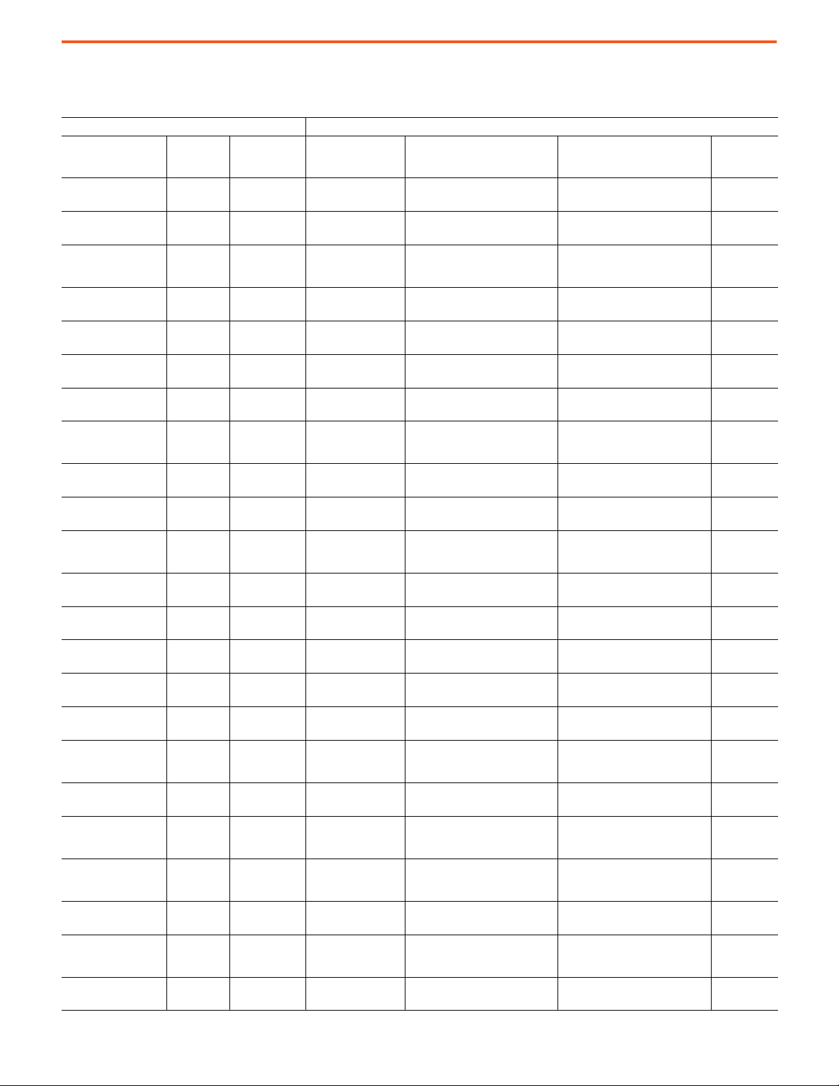
PowerFlex 7000 Medium Voltage AC Drives Technical Data
PowerFlex ‘B’ Frame
Maximum Line Cable Size
Product Input (Line Side)
Voltage/Frequency/
Rectifier
2400V/60 Hz/RPDTD 46…375
3300V/50 Hz/RPDTD 46…430
3300V/50 Hz/RPDTD
3300V/50 Hz/RPDTD 46…375
4160V/50 Hz/RPDTD 46…375
4160V/50 Hz/RPDTD 46…375
4160V/60 Hz/RPDTD 46…430
4160V/60 Hz/RPDTD
4160V/60 Hz/RPDTD 46…375
6600V/50 Hz/RPDTD 40…285
6600V/50 Hz/RPDTD
6600V/50 Hz/RPDTD 40…285
6600V/60 Hz/RPDTD 40…285
6600V/60 Hz/RPDTD 40…285
2400V/60 Hz/RPTX 46…430
3300V/50 Hz/RPTX 46…430
3300V/50 Hz/RPTX
4160V/50 Hz/RPTX 46…430
4160V/60 Hz/RPTX 46…430
4160V/60 Hz/RPTX
6600V/50 Hz/RPTX 40…285
6600V/50 Hz/RPTX
2400V/60 Hz/RP18TX
Drive
Rating (A)
E495…E625,
G285, G325,
N720
E495…E625,
G285, G325,
N720
E325…E575,
G215, G250,
N625, N625
E495…E625,
G285, G325,
N720
E495…E625,
G285, G325,
N720
E325…E575,
G215, G250,
N625
(9)
46…430 70.8
Drive Structure
Code
70.40C, 70.41C,
(8)
7.44C
70.43, 70.44,
70.45, 70.47
70.32
70.43C, 70.44C,
70.45C, 70.47C
70.43, 70.44,
70.45, 70.47
70.43C, 70.44C,
70.45C, 70.47C
70.43, 70.44,
70.45, 70.47
70.32
70.43C, 70.44C,
70.45C, 70.47C
70.46, 70.47,
70.48, 70.49
70.34, 70.35
70.46C, 70.47C,
(8)
70.49C
70.46, 70.47,
70.48, 70.49
70.46C, 70.47C,
(8)
70.49C
70.1, 70.2, 70.25,
70.26
70.10, 70.27,
70.28, 70.30
70.32
70.10, 70.27,
70.29, 70.30
70.2, 70.26,
70.27, 70.28,
70.29, 70.31
70.32
70.11, 70.28,
70.30. 70.31
70.36, 70.37
(8)
(8)
(8)
Line Cable Conduit
Opening [in. (mm)]
5.61 x 7.19
(142 x 183)
9.79 x 10.97
(249 x 279)
11.81 x 16.22
(300 x 412)
(1)
(1)
5.61 x 7.19
(142 x 183)
9.79 x 10.97
(249 x 279)
(1)
5.61 x 7.19
(142 x 183)
9.79 x 10.97
(249 x 279)
11.81 x 16.22
(300 x 412)
(1)
(1)
5.61 x 7.19
142 x 183)
9.79 x 10.97
(249 x 279)
12.79 x 19.68
(325 x 500)
(1)
(1)
5.61 x 7.19
(142 x 183)
9.79 x 10.97
(249 x 279)
(1)
5.61 x 7.19
(142 x 183)
9.79 x 10.97
(249 x 279)
9.79 x 10.97
(249 x 279)
(300 x 412)
9.79 x 10.97
(249 x 279)
9.79 x 10.97
(249 x 279)
11.81 x 16.22
(300 x 412)
9.79 x 10.97
(249 x 279)
12.79 x 19.68
(325 x 500)
9.79 x 21.06
(249 x 535)
11.81 x16.22
(1)
(1)
(1)
(1)
(1)
(1)
(1)
(1)
(1)
No. and Max. Size of Incoming
(1)
Cables (NEMA)
(2)(3)(4)(5)(6)(7)
One 500 MCM/phase (5 kV or 8 kV)
Two 500 MCM/phase (5 kV or 8 kV)
Two 500 MCM/phase (5 kV or 8 kV)
One 500 MCM/phase (5 kV or 8 kV)
Two 500 MCM/phase (5 kV or 8 kV)
One 500 MCM/phase (5 kV or 8 kV)
Two 500 MCM/phase (5 kV or 8 kV)
Two 500 MCM/phase (5 kV or 8 kV)
One 500 MCM/phase (5 kV or 8 kV)
Two 500 MCM/phase (8 kV or 15 kV)
Two 500 MCM/phase (8 kV or 15 kV)
One 500 MCM/phase (8 kV or 15 kV)
Two 500 MCM/phase (8 kV or 15 kV)
One 500 MCM/phase (8 kV or 15 kV)
Two 500 MCM/phase (8 kV or 15 kV)
Two 500 MCM/phase (8 kV or 15 kV)
Two 500 MCM/phase (5 kV or 8 kV)
Two 500 MCM/phase (8 kV or 15 kV)
Two 500 MCM/phase (8 kV or 15 kV)
Two 500 MCM/phase (5 kV or 8 kV)
Two 250 MCM/phase (15 kV)
Two 500 MCM/phase (8 kV or 15 kV)
Two 500 MCM/sec ond ary w indin g
(5 kV or 8 kV)
No. and Max. Size of Incoming
Cables (IEC)
One 253 mm
Two 253 mm
Two 253 mm
One 253 mm
Two 253 mm
One 253 mm
Two 253 mm
Two 253 mm
One 253 mm
Two 253 mm
Two 253 mm
One 253 mm
Two 253 mm
One 253 mm
Two 253 mm
Two 253 mm
Two 253 mm
Two 253 mm
Two 253 mm
Two 253 mm
Two 127 mm
Two 253 mm
Two 253 mm
(2)(3)(4)(5)(6)(7)
2
/phase (5 kV or 8 kV)
2
/phase (5 kV or 8 kV)
2
/phase (5 kV or 8 kV)
2
/phase (5 kV or 8 kV)
2
/phase (5 kV or 8 kV)
2
/phase (5 kV or 8 kV)
2
/phase (8 kV or 15 kV)
2
/phase (5 kV or 8 kV)
2
/phase (8 kV or 15 kV)
2
/phase (8 kV or 15 kV)
2
/phase (8 kV or 15 kV)
2
/phase (8 kV or 15 kV)
2
/phase (5 kV or 8 kV)
2
/phase (5 kV or 8 kV)
2
/phase (5 kV or 8 kV)
2
/phase (5 kV or 8 kV)
2
/phase (5 kV or 8 kV)
2
/phase (5 kV or 8 kV)
2
/phase (8 kV or 15 kV)
2
/phase (5 kV or 8 kV)
2
/phase (15 kV)
2
/phase (8 kV or 15 kV)
2
/secondary winding
(5 kV or 8 kV)
Space for
Stress Cones
[in. (mm)]
34.4 (874)
28.5 (725)
16.5 (421)
34.4 (874)
28.5 (725)
34.4 (874)
28.5 (725)
16.5 (421)
34.4 (874)
28.5 (725)
16.5 (421)
34.4 (874)
28.5 (725)
34.4 (874)
28.5 (725)
28.5 (725)
16.5 (421)
28.5 (725)
28.5 (725)
16.5 (421)
28.5 (725)
16.5 (421)
17.7 (449)
42 Rockwell Automation Publication 7000-TD010A-EN-P - March 2021
PowerFlex 7000 Medium Voltage AC Drives Technical Data
Maximum Line Cable Size (Continued)
Product Input (Line Side)
Voltage/Frequency/
Rectifier
3300V/50 Hz/RP18TX
4160V/50 Hz/RP18TX
4160V/60 Hz/RP18TX
6600V/50 Hz/RP18TX
6600V/50 Hz/RP18TX
6600V/60 Hz/RP18TX
6600V/60 Hz/RP18TX
(1) Most PowerFlex ‘B’ frame drives have a single enclosure opening provision for both line and load cables. Most ‘B’ frames have separate opening provisions for line and load cables. All cabling
capacities that are shown in this table are “worst case” conditions when both line and load cabling enters and exits in the same direction.
(2) Cable sizes are based on overall dimensions of compact-stranded three-conductor shielded cable (common for industrial cable tray installations). Maximum sizing stated accounts for
minimum rated cable insulation requirements and the next higher-rated cable (for example, 8 kV is not commercially available in many areas of the world, therefore Rockwell Automation
provides an 8 kV (minimum rating) as well as a 15 kV rating, when applicable. Enclosure openings will accommodate the thicker insulation on the higher-rated cable. IEC ratings show the
equivalent to the NEMA sizes. The exact cable mm
(3) Minimum cable bend radius recommendations vary by national codes, cable type, and cable size. Consult local codes for guidelines and requirements. General relationship of cable diameter
to bend radius is typically between 7…12x (for example, if the cable diameter is 1 in. [2.54 cm] the minimum bend radius could range between 7…12 in. [18.8…30.48 cm]).
(4) For minimum cable insulation requirements, see the PowerFlex 7000 user manual for your particular frame. Stated voltages are peak line-to-ground. Some cable manufacturers rate cabling
based on RMS line-to-line.
(5) Ground lug capabilities: up to ten mechanical range lugs for ground cable connections are available, typically these frames supply four. Mechanical range lugs can accommodate cable size
#6…250MCM (13.3…127 mm
(6) Maximum cable size for ‘B’ Frame (two per phase) is 500 MCM (253 mm2), limited by lug pad assembly size and clearance requirements.
(7) As cabling methods can vary widely, maximum cable sizes shown do not account for the size of the conduit hub. Verify size of conduit hub(s) against the line cable conduit openings shown.
(8) With a close-coupled starter.
(9) 18-pulse drives have nine line-side connections (from the secondary windings of the isolation transformer) which enter the drive. Lug pads are provided for each connection. The lug pad
and enclosure opening can generally accommodate two cables per connection (18 cables total).
Drive
Rating (A)
(9)
46…430 70.9
(9)
46…430 70.9, 70.18
(9)
46…430 70.8, 70.9
(9)
40…215 70.9
(9)
250…430 70.18
(9)
40…215 70.9
(9)
250…430 70.18
2
).
Drive Structure
Code
2
size shown is not commercially available in many cases; use the next smaller standard size.
Line Cable Conduit
Opening [in. (mm)]
9.79 x 21.06
(249 x 535)
9.79 x 21.06
(249 x 535)
9.79 x 21.06
(249 x 535)
9.79 x 21.06
(249 x 535)
9.79 x 21.06
(249 x 535)
9.79 x 21.06
(249 x 535)
9.79 x 21.06
(249 x 535)
No. and Max. Size of Incoming
(1)
Cables (NEMA)
Two 500 MCM/sec ond ary w indin g
(1)
(1)
(1)
(1)
(1)
(1)
(1)
(8 kV or 15 kV)
Two 500 MCM/sec ond ary w indin g
(8 kV or 15 kV)
Two 500 MCM/sec ond ary w indin g
(8 kV or 15 kV)
Two 350 MCM/se cond ary win ding
Two 350 MCM/se cond ary win ding
Two 350 MCM/se cond ary win ding
Two 350 MCM/se cond ary win ding
(2)(3)(4)(5)(6)(7)
(15 kV)
(15 kV)
(15 kV)
(15 kV)
No. and Max. Size of Incoming
Cables (IEC)
Two 253 mm
(2)(3)(4)(5)(6)(7)
2
/secondary winding
(8 kV or 15 kV)
Two 253 mm
2
/secondary winding
(8 kV or 15 kV)
Two 253 mm
2
/secondary winding
(8 kV or 15 kV)
Two 177 mm
2
/secondary winding
(15 kV)
Two 177 mm
2
/secondary winding
(15 kV)
Two 177 mm
2
/secondary winding
(15 kV)
Two 177 mm
2
/secondary winding
(15 kV)
Space for
Stress Cones
[in. (mm)]
17.7 (449)
17.7 (449)
17.7 (449)
17.7 (449)
17.7 (449)
17.7 (449)
17.7 (449)
Rockwell Automation Publication 7000-TD010A-EN-P - March 2021 43

PowerFlex 7000 Medium Voltage AC Drives Technical Data
PowerFlex ‘B’ Frame
Maximum Load Cable Size
Product Output (Motor Side)
Voltage/Frequency/
Rectifier
2400V/60 Hz/RPDTD 46…430
2400V/60 Hz/RPDTD 46…375
3300V/50 Hz/RPDTD 46…430
3300V/50 Hz/RPDTD
3300V/50 Hz/RPDTD 46…375
4160V/50 Hz/RPDTD 46…375
4160V/50 Hz/RPDTD 46…375
4160V/60 Hz/RPDTD 46…430
4160V/60 Hz/RPDTD
4160V/60 Hz/RPDTD 46…375
6600V/50 Hz/RPDTD 40…285
6600V/50 Hz/RPDTD 40…285
6600V/50 Hz/RPDTD
6600V/60 Hz/RPDTD 40…285
6600V/60 Hz/RPDTD 40…285
2400V/60 Hz/RPTX 46…430
3300V/50 Hz/RPTX 46…430
3300V/50 Hz/RPTX
4160V/50 Hz/RPTX 46…430
4160V/60 Hz/RPTX 46…430
4160V/60 Hz/RPTX
6600V/50Hz/RPTX 40…285
Drive
Rating (A)
E495…E625,
G285, G325,
N720
E495…E625,
G285, G325,
N720
E325…E575,
G215, G250,
N625, N625
E495…E625,
G285, G325
N720
E495…E625,
G285, G325,
N720
Drive Structure
Code
70.40, 70.41,
70.44, 70.45
70.40C, 70.41C,
(8)
7.44C
70.43, 70.44,
70.45, 70.47
70.32
70.43C, 70.44C,
70.45C, 70.47C
(8)
70.43, 70.44,
70.45, 70.47
70.43C, 70.44C,
70.45C, 70.47C
(8)
70.43, 70.44,
70.45, 70.47
70.32
70.43C, 70.44C,
70.45C, 70.47C
(8)
70.46, 70.47,
70.48, 70.49
70.46C, 70.47C,
(8)
70.49C
70.34, 70.35
70.46, 70.47,
70.48, 70.49
70.46C, 70.47C,
70.49C
(8)
70.1, 70.2, 70.25,
70.26
70.10, 70.27,
70.28, 70.30
70.32
70.10, 70.27,
70.29, 70.30
70.2, 70.26, 70.27,
70.28,
70.29, 70.31
70.32
70.11, 70.28,
70.30. 70.31
Load Cable
Conduit Opening
[in. (mm)]
9.79 x 10.97
(249 x 279)
(1)
(1)
6.52 x 9.88
(168 x 251)
9.79 x 10.97
(249 x 279)
11.81 x 16.22
(300 x 412)
(1)
(1)
6.52 x 9.88
(168 x 251)
9.79 x 10.97
(249 x 279)
(1)
6.52 x 9.88
(168 x 251)
9.79 x 10.97
(249 x 279)
11.81 x 16.22
(300 x 412)
(1)
(1)
6.52 x 9.88
(168 x 251)
9.79 x 10.97
(249 x 279) (1)
6.52 x 9.88
(168 x 251)
12.79 x 19.68
(325 x 500)
9.79 x 10.97
(249 x 279)
(1)
(1)
6.52 x 9.88
(168 x 251)
9.79 x 10.97
(249 x 279)
9.79 x 10.97
(249 x 279)
11.81 x 16.22
(300 x 412)
9.79 x 10.97
(249 x 279)
9.79 x 10.97
(249 x 279)
11.81 x 16.22
(300 x 412)
9.79 x 10.97
(249 x 279)
(1)
(1)
(1)
(1)
(1)
(1)
(1)
No. and Max. Size of Outgoing
Cables (NEMA)
(2)(3)(4)(5)(6)(7)
Two 500 MCM/phase (5 kV or 8 kV)
One 500 MCM/phase (5 kV) or
Two 250 MCM/phase (5 kV or 8 kV)
Two 500 MCM/phase (5 kV or 8 kV)
Two 500 MCM/phase (5 kV or 8 kV)
One 500 MCM/phase (5 kV) or
Two 250 MCM/phase (5 kV or 8 kV)
Two 500 MCM/phase (5 kV or 8 kV)
One 500 MCM/phase (5 kV) or
Two 250 MCM/phase (5 kV or 8 kV)
Two 500 MCM/phase (5 kV or 8 kV)
Two 500 MCM/phase (5 kV or 8 kV)
One 500 MCM/phase (5 kV) or
Two 250 MCM/phase (5 kV or 8 kV)
Two 500 MCM/phase (8 kV)
One 500 MCM/phase (5 kV) or
Two 250 MCM/phase (8 kV or 15 kV)
Two 500 MCM/phase (8 kV or 15 kV)
Two 500 MCM/phase (8 kV or 15 kV)
One 500 MCM/phase (5 kV) or
Two 250 MCM/phase (8 kV or 15 kV)
Two 500 MCM/phase (5 kV or 8 kV)
Two 500 MCM/phase (5 kV or 8 kV)
Two 500 MCM/phase (5 kV or 8 kV)
Two 500 MCM/phase (5 kV or 8 kV)
Two 500 MCM/phase (5 kV or 8 kV)
Two 500 MCM/phase (5 kV or 8 kV)
Two 500 MCM/phase (8 kV or 15 kV)
No. and Max. Size of Outgoing
Cables (IEC)
Two 253 mm
One 253 mm2/phase (5 kV or 8 kV) or
Two 127 mm
Two 253 mm
Two 253 mm
One 253 mm2/phase (5 kV or 8 kV) or
Two 127 mm
Two 253 mm
One 253 mm2/phase (5 kV or 8 kV) or
Two 127 mm
Two 253 mm
Two 253 mm
One 253 mm2/phase (5 kV or 8 kV) or
Two 127 mm
Two 253 mm
One 253 mm2/phase (8 kV or 15 kV) or
Two 127 mm
Two 253 mm
Two 253 mm
One 253 mm2/phase (8 kV or 15 kV) or
Two 127 mm
Two 253 mm
Two 253 mm
Two 253 mm
Two 253 mm
Two 253 mm
Two 253 mm
Two 253 mm
(2)(3)(4)(5)(6)(7)
2
/phase (5 kV or 8 kV)
2
/phase (5 kV or 8 kV)
2
/phase (5 kV or 8 kV)
2
/phase (5 kV or 8 kV)
2
/phase (5 kV or 8 kV)
2
/phase (5 kV or 8 kV)
2
/phase (5 kV or 8 kV)
2
/phase (5 kV or 8 kV)
2
/phase (5 kV or 8 kV)
2
/phase (5 kV or 8 kV)
2
/phase (5 kV or 8 kV)
2
/phase (8 kV or 15 kV)
2
/phase (8 kV or 15 kV)
2
/phase (5 kV or 8 kV)
2
/phase (8 kV or 15 kV)
2
/phase (5 kV or 8 kV)
2
/phase (5 kV or 8 kV)
2
/phase (5 kV or 8 kV)
2
/phase (5 kV or 8 kV)
2
/phase (5 kV or 8 kV)
2
/phase (5 kV or 8 kV)
2
/phase (8 kV or 15 kV)
Space for
Stress Cones
[in. (mm)]
28.5 (725)
16.2 (411)
28.5 (725)
16.5 (421)
16.2 (411)
28.5 (725)
16.2 (411)
28.5 (725)
16.5 (421)
16.2 (411)
28.5 (725)
16.2 (411)
16.5 (421)
28.5 (725)
16.2 (411)
28.5 (725)
28.5 (725)
16.5 (421)
28.5 (725)
28.5 (725)
16.5 (421)
28.5 (725)
44 Rockwell Automation Publication 7000-TD010A-EN-P - March 2021

PowerFlex 7000 Medium Voltage AC Drives Technical Data
Maximum Load Cable Size
Product Output (Motor Side)
Voltage/Frequency/
Rectifier
Drive
Rating (A)
Drive Structure
Code
E325…E575,
6600V/50 Hz/RPTX
G215, G250,
70.36, 70.37
N625
(9)
2400V/60Hz/RP18TX
3300V/50Hz/RP18TX
4160V/50Hz/RP18TX
4160V/60Hz/RP18TX
6600V/50Hz/RP18TX
6600V/50Hz/RP18TX
6600V/60Hz/RP18TX
6600V/60Hz/RP18TX
(1) Most PowerFlex ‘B’ frame drives have a single enclosure opening provision for both line and load cables. Most ‘B’ frames have separate opening provisions for line and load cables. All cabling
capacities that are shown in this table are “worst case” conditions when both line and load cabling enters and exits in the same direction.
(2) Cable sizes are based on overall dimensions of compact-stranded three-conductor shielded cable (common for industrial cable tray installations). Maximum sizing stated accounts for
minimum rated cable insulation requirements and the next higher-rated cable (for example, 8 kV is not commercially available in many areas of the world, therefore Rockwell Automation
provides an 8 kV (minimum rating) as well as a 15 kV rating, when applicable. Enclosure openings will accommodate the thicker insulation on the higher-rated cable. IEC ratings show the
equivalent to the NEMA sizes. The exact cable mm
(3) Minimum cable bend radius recommendations vary by national codes, cable type, and cable size. Consult local codes for guidelines and requirements. General relationship of cable diameter
to bend radius is typically between 7…12x (for example, if the cable diameter is 1 in. [2.54 cm] the minimum bend radius could range between 7…12 in. [18.8…30.48 cm]).
(4) For minimum cable insulation requirements, see the PowerFlex 7000 user manual for your particular frame. Stated voltages are peak line-to-ground. Some cable manufacturers rate cabling
based on RMS line-to-line.
(5) Ground lug capabilities: up to ten mechanical range lugs for ground cable connections are available, typically these frames supply four. Mechanical range lugs can accommodate cable size
#6…250MCM (13.3…127 mm
(6) Maximum cable size for ‘B’ Frame (two per phase) is 500 MCM (253 mm
(7) As cabling methods can vary widely, maximum cable sizes shown do not account for the size of the conduit hub. Verify size of conduit hub(s) against the load cable conduit openings shown.
(8) With a close-coupled starter.
(9) 18-pulse drives have nine line-side connections (from the secondary windings of the isolation transformer) which enter the drive. Lug pads are provided for each connection. The lug pad
and enclosure opening can generally accommodate two cables per connection (18 cables total).
46…430 70.8
(9)
46…430 70.9
(9)
46…430 70.9, 70.18
(9)
46…430 70.8, 70.9
(9)
40…215 70.9
(9)
250…430 70.18
(9)
40…215 70.9
(9)
250…430 70.18
2
).
2
size shown is not commercially available in many cases; use the next smaller standard size.
Load Cable
Conduit Opening
[in. (mm)]
12.79 x 19.68
(325 x 500)
9.79 x 10.97
(249 x 279)
9.79 x 10.97
(249 x 279)
9.79 x 10.97
(249 x 279)
9.79 x 10.97
(249 x 279)
9.79 x 10.97
(249 x 279)
9.79 x 10.97
(249 x 279)
9.79 x 10.97
(249 x 279)
9.79 x 10.97
(249 x 279)
2
), limited by lug pad assembly size and clearance requirements.
No. and Max. Size of Outgoing
Cables (NEMA)
(1)
Two 500 MCM/phase (8 kV or 15 kV)
(1)
Two 500 MCM/phase (5 kV or 8 kV)
(1)
Two 500 MCM/phase (5 kV or 8 kV)
(1)
Two 500 MCM/phase (5 kV or 8 kV)
(1)
Two 500 MCM/phase (5 kV or 8 kV)
(1)
Two 500 MCM/phase (8 kV or 15 kV)
(1)
Two 500 MCM/phase (8 kV or 15 kV)
(1)
Two 500 MCM/phase (8 kV or 15 kV)
(1)
Two 500 MCM/phase (8 kV or 15 kV)
(1)
(2)(3)(4)(5)(6)(7)
No. and Max. Size of Outgoing
Cables (IEC)
Two 253 mm
Two 253 mm
Two 253 mm
Two 253 mm
Two 253 mm
Two 253 mm
Two 253 mm
Two 253 mm
Two 253 mm
(2)(3)(4)(5)(6)(7)
2
/phase (8 kV or 15 kV)
2
/phase (5 kV or 8 kV)
2
/phase (5 kV or 8 kV)
2
/phase (5 kV or 8 kV)
2
/phase (5 kV or 8 kV)
2
/phase (8 kV or 15 kV)
2
/phase (8 kV or 15 kV)
2
/phase (8 kV or 15 kV)
2
/phase (8 kV or 15 kV)
Space for
Stress Cones
[in. (mm)]
16.5 (421)
16.4 (415)
16.4 (415)
16.4 (415)
16.4 (415)
16.4 (415)
16.4 (415)
16.4 (415)
16.4 (415)
Rockwell Automation Publication 7000-TD010A-EN-P - March 2021 45
PowerFlex 7000 Medium Voltage AC Drives Technical Data
PowerFlex ‘C’ Frame
Maximum Line Cable Sizes
Product Input (Line Side)
Voltage/Frequency/
Rectifier
4160V/50 Hz/RPDTD 375…575
4160V/60 Hz/RPDTD 375…625
Drive
Rating (A)
Drive Structure Code
70.71 (L-A), 70.72 (L-L), 70.76 (L-A)
70.77 (L-L), 70.89 (L-A), 70.94 (L-L)
70.71 (L-A), 70.72 (L-L), 70.76 (L-A),
70.77 (L-L)
70.80 (L-A), 70.85 (L-L), 70.86 (L-L),
6600V/50 Hz/RPDTD 325…575
70.87 (L-L), 70.88 (L-L), 70.91 (LA), 70.92 (L-A)
70.80 (L-A), 70.85 (L-L), 70.86 (L-L),
6600V/60 Hz/RPDTD 325…575
70.87 (L-L), 70.88 (L-L), 70.91 (L-A),
70.92 (L-A), 70.93 (L-A)
(8)
4160V/50 Hz/R18TX
4160V/60 Hz/R18TX
6600V/50 Hz/R18TX
6600V/60 Hz/R18TX
(1) All ‘C’ frame drives have a single enclosure opening provision for both line and load cables. All cabling capacities that are shown are for “worst case” condition when both line and load
cabling enters and exits the same direction.
(2) Cable sizes are based on overall dimensions of compact-stranded three-conductor shielded cable (typical industrial cable used for cable tray installations). Maximum sizing stated accounts
for minimum rated cable insulation requirements and the next higher rated cable, i.e. 8 kV is not commercially available in many areas of the world, therefore an 8 kV (minimum rating) as
well as a 15 kV rating is given, when applicable. Enclosure openings will accommodate the thicker insulation on the higher rated cable. IEC ratings show the equivalent to the NEMA sizes. The
exact cable mm
(3) Minimum cable bend radius recommendations vary by national codes, cable type, and cable size. Consult local codes for guidelines and requirements. General relationship of cable diameter
to bend radius is typically between 7…12x (for example, if the cable diameter is 1 in. [2.54 cm] the minimum bend radius could range between 7…12 in. [18.8…30.48 cm]).
(4) For minimum cable insulation requirements, see the PowerFlex 7000 user manual for your particular frame. Stated voltages are peak line-to-ground. Some cable manufacturers rate cabling
based on RMS line-to-line.
(5) Ground lug capabilities: up to ten mechanical range lugs for ground cable connections can be provided. Four mechanical range lugs for ground cable connections are typically supplied.
Mechanical range lugs can accommodate cable sizes of #6…250 MCM (13.3…127 mm
(6) Maximum cable size ‘C’ Frame (four per phase) is 500 MCM (253 mm2). Limited by lug pad assembly size and clearance requirements.
(7) As cabling methods can vary widely, maximum cable sizes shown do not account for the size of a conduit hub. Verify size of conduit hub(s) against the “Drive Enclosure Openings” shown.
(8) 18 pulse drives (R18TX) have nine line-side connections (from the secondary windings of the isolation transformer) entering the VFD. Lug pads are provided for each connection. The lug pad
and enclosure opening can generally accommodate two cables per connection (18 cables total).
375…657 70.50 (L-A), 70.55 (L-L)
(8)
375…657 70.50 (L-A), 70.55 (L-L)
(8)
375…657
(8)
375…657
2
size stated is not commercially available in many cases; use the next smaller standard size.
70.50 (L-A), 70.53 (L-A), 70.55 (LL), 70.58 (L-L)
70.50 (L-A), 70.53 (L-A), 70.55 (LL), 70.58 (L-L)
Line Cable
Conduit Opening
[in. (mm)]
11.22 x 23.62
(285 x 600)
11.22 x 23.62
(285 x 600)
11.22 x 23.62
(285 x 600)
11.22 x 23.62
(285 x 600)
9.79 x 21.06
(249 x 535)
9.79 x 21.06
(249 x 535)
9.79 x 21.06
(249 x 535)
9.79 x 21.06
(249 x 535)
2
).
Max. Size and No. of Incoming Cables
(1)
(NEMA)
(2)(3)(4)(5)(6)(7)
Four 500 MCM/phase (5 kV or 8 kV)
Four 500 MCM/phase (5 kV or 8 kV)
Four 500 MCM/phase (8 kV or 15kV)
Four 500 MCM/phase (8 kV or 15kV)
Two 500 MCM/secondary winding
(8 kV or 15 kV)
Two 500 MCM/secondary winding
(8 kV or 15 kV)
Two 350 MCM/secondary winding (15 kV)
Two 350 MCM/secondary winding (15 kV)
Max. Size and No. of
Incoming Cables
(2)(3)(4)(5)(6)(7)
(IEC)
Four 253 mm2/phase
(5 kV or 8 kV)
Four 253 mm
2
/phase
(5 kV or 8 kV)
Four 253 mm2/phase
(8 kV or 15 kV)
2
Four 253 mm
/phase
(8 kV or 15 kV)
Two 253 mm
2
/
secondary winding
(8 kV or 15 kV)
Two 253 mm
2
/
secondary winding
(8 kV or 15 kV)
Two 177 mm
2
/
secondary winding
(15 kV)
Two 177 mm
2
/
secondary winding
(15 kV)
Space for
Stress Cone s
[in. (mm)]
18.0 (457)
18.0 (457)
18.0 (457)
18.0 (457)
17.7 (449)
17.7 (449)
17.7 (449)
17.7 (449)
46 Rockwell Automation Publication 7000-TD010A-EN-P - March 2021
PowerFlex 7000 Medium Voltage AC Drives Technical Data
PowerFlex ‘C’ Frame
Maximum Load Cable Sizes
Product Output (Motor Side)
Voltage/Frequency/
Rectifier
4160V/50 Hz/RPDTD 375…575
4160V/60 Hz/RPDTD 375…625
Drive
Rating (A)
Drive Structure Code
70.71 (L-A), 70.72 (L-L), 70.76 (L-A)
70.77 (L-L), 70.89 (L-A), 70.94 (L-L)
70.71 (L-A), 70.72 (L-L), 70.76 (L-A)
70.77 (L-L)
70.80 (L-A), 70.85 (L-L), 70.86 (L-L),
6600V/50 Hz/RPDTD 325…575
70.87 (L-L), 70.88 (L-L),
70.91 (L-A), 70.92 (L-A)
70.80 (L-A), 70.85 (L-L), 70.86 (L-L),
6600V/60 Hz/RPDTD 325…575
70.87 (L-L), 70.88 (L-L), 70.91 (L-A),
70.92 (L-A), 70.93 (L-A)
(8)
4160V/50 Hz/R18TX
375…657 70.50 (L-A), 70.55 (L-L)
4160V/60 Hz/R18TX 375…657 70.50 (L-A), 70.55 (L-L)
6600V/50 Hz/R18TX 375…657
6600V/60 Hz/R18TX 375…657
(1) All ‘C’ frame drives have a single enclosure opening provision for both line and load cables. All cabling capacities that are shown are for “worst case” condition when both line and load
cabling enters and exits the same direction.
(2) Cable sizes are based on overall dimensions of compact-stranded three-conductor shielded cable (typical industrial cable used for cable tray installations). Maximum sizing stated accounts
for minimum rated cable insulation requirements and the next higher rated cable, i.e. 8 kV is not commercially available in many areas of the world, therefore an 8 kV (minimum rating) as
well as a 15 kV rating is given, when applicable. Enclosure openings will accommodate the thicker insulation on the higher rated cable. IEC ratings show the equivalent to the NEMA sizes. The
exact cable mm
(3) Minimum cable bend radius recommendations vary by national codes, cable type, and cable size. Consult local codes for guidelines and requirements. General relationship of cable diameter
to bend radius is typically between 7…12x (for example, if the cable diameter is 1 in. [2.54 cm] the minimum bend radius could range between 7…12 in. [18.8…30.48 cm]).
(4) For minimum cable insulation requirements, see the PowerFlex 7000 user manual for your particular frame. Stated voltages are peak line-to-ground. Some cable manufacturers rate cabling
based on RMS line-to-line.
(5) Ground lug capabilities: up to ten mechanical range lugs for ground cable connections can be provided. Four mechanical range lugs for ground cable connections are typically supplied.
Mechanical range lugs can accommodate cable sizes of #6…250 MCM (13.3…127 mm
(6) Maximum cable size ‘C’ Frame (four per phase) is 500 MCM (253 mm2). Limited by lug pad assembly size and clearance requirements.
(7) Because cabling methods can vary widely, maximum cable sizes shown do not account for the size of a conduit hub. Verify size of conduit hub(s) against the “Drive Enclosure Openings”
shown.
(8) 18 pulse drives (R18TX) have nine line-side connections (from the secondary windings of the isolation transformer) entering the VFD. Lug pads are provided for each connection. The lug pad
and enclosure opening can generally accommodate two cables per connection (18 cables total).
2
size stated is not commercially available in many cases; use the next smaller standard size.
70.50 (L-A), 70.53 (L-A),
70.55 (L-L), 70.58 (L-L)
70.50 (L-A), 70.53 (L-A),
70.55 (L-L), 70.58 (L-L)
Load Cable
Conduit Opening
[in. (mm)]
11.22 x 23.62
(285 x 600)
11.22 x 23.62
(285 x 600)
11.22 x 23.62
(285 x 600)
11.22 x 23.62
(285 x 600)
9.79 x 21.06
(249 x 535)
9.79 x 21.06
(249 x 535)
9.79 x 21.06
(249 x 535)
9.79 x 21.06
(249 x 535)
2
).
Max. Size and No. of Incoming Cables
(1)
(NEMA)
(2)(3)(4)(5)(6)(7)
Four 500 MCM/phase (5 kV or 8 kV)
Four 500 MCM/phase (5 kV or 8 kV)
Four 500 MCM/phase (8 kV or 15kV)
Four 500 MCM/phase (8 kV or 15kV)
Two 500 MCM/phase (5 kV or 8 kV)
Two 500 MCM/phase (5 kV or 8 kV)
Two 500 MCM/phase (8 kV or 15kV)
Two 500 MCM/phase (8 kV or 15kV)
Max. Size and No. of
Incoming Cables
(2)(3)(4)(5)(6)(7)
(IEC)
Four 253 mm2/phase
(5 kV or 8 kV)
Four 253 mm
2
/phase
(5 kV or 8 kV)
Four 253 mm2/phase
(8 kV or 15 kV)
2
Four 253 mm
/phase
(8 kV or 15 kV)
Two 253 mm
2
/phase
(5 kV or 8 kV)
Two 253 mm
2
/phase
(5 kV or 8 kV)
Two 253 mm
2
/phase
(8 kV or 15 kV)
2
Two 253 mm
/phase
(8 kV or 15 kV)
Space for
Stress Cone s
[in. (mm)]
16.4 (415)
16.4 (415)
16.4 (415)
16.4 (415)
16.4 (415)
16.4 (415)
16.4 (415)
16.4 (415)
Rockwell Automation Publication 7000-TD010A-EN-P - March 2021 47

PowerFlex 7000 Medium Voltage AC Drives Technical Data
Encoder Selection
An encoder is required under any of the following conditions:
• When speed regulation accuracy must be between 0.01…0.02% of nominal speed.
• When the zero-speed breakaway torque needed is greater than 90% of continuous running torque.
• When continuous running speed is greater than or equal to 0.1 Hz, but less than 6 Hz.
• For minimizing restart times using the flying start capability in forward or reverse direction.
• At any time when HPTC is enabled.
PowerFlex Speed Regulation
Encoder
Without Encoder — 0.1% 0.1%
With Encoder 0.02% 0.01% 0.01%
With Encoder and HPTC mode enabled 0.01% 0.01% 0.01%
<6 Hz 6…15 Hz >15 Hz
Frequency Output
Notes:
• Speed regulation is based on a percentage of motor synchronous speed
• Encoder to be mounted on the AC machine
• Operational 15V DC power supply mounted in drive to power the Encoder as a standard option with the encoder feedback card
• You are responsible for providing and mounting the encoder
• Sleeve bearing motors require the encoder to have an axial movement tolerance
• Recommended encoders are shaft mounting type, examples are the Avtron 685 or the NexGen RIM Tach 8500, 12…15V models or
equivalent. Magneto resistive models are more adaptable to harsh environments
• If possible, use encoders without Marker, Index, Z, or sig. C signals, as these are not used on the PowerFlex 7000 drive
• When installing, the encoder body and electronics must be isolated from ground (options available from the encoder manufacturer)
• When cable lengths exceed 305 m (1000 ft) for the Northstar tachometer or 610 m (2000 ft) for the Avtron tachometer, consult your
local sales office or distributor
Encoder Selection
Motor RPM Minimum Tach PPR Recommended Tach PPR
3600 1024 1024
3000 1024 1024
1800 1024 2048
1500 1024 2048
1200 2048 2048
HPTC Mode
1000 2048 2048
900 2048 4096
720 4096 4096
600 4096 4096
450 4096 8192
360 8192 8192
300 8192 8192
48 Rockwell Automation Publication 7000-TD010A-EN-P - March 2021

PowerFlex 7000 Medium Voltage AC Drives Technical Data
Encoder Selection
3600 — 600
3000 — 600
1800 — 1024
1500 — 1024
Standard Control Mode
1200 — 2048
1000 — 2048
900 — 2048
720 — 2048
600 — 2048
Drive Torque Capabilities
PowerFlex 7000 drives are tested on a dynamometer to verify performance under locked rotor, accelerating, and low speed-high torque
conditions. The following table shows the drive torque capabilities as a percent of motor rated torque, independent of the momentary
overload conditions of the drive.
PowerFlex 7000 Drive Torque Capabilities
Parameter
Breakaway Torque 90% 150% 150%
Accelerating Torque
Steady State Torque
Maximum Torque Limit 150% 150% 150%
(1) Drive will require over-sizing to achieve greater than 100% continuous torque.
Torque Capability without Encoder
(% of Motor Rated Torque)
90% (0…8 Hz) 140% (0…8 Hz)
125% (9…75 Hz) 140% (9…75 Hz)
125% (9…75 Hz)
(1)
Torque Capability with Encoder
(% of Motor Rated Torque)
100% (1…2 Hz)
140% (3…60 Hz)
(1)
Torque Capability with Encoder and HPTC
150% (0…75 Hz)
150% (0…60 Hz)
Definitions
Parameter Definitions
Parameter Description
Breakaway Torque Torque required to start a machine from standstill.
Torque required to accelerate a load to a given speed, in a certain period of time.
The following formula may be used to calculate the average torque to accelerate a known inertia (Wk
Accelerating Torque
Steady State Torque Continuous operating torque required to control the load, without instability.
Max. Torque Limit
T = (Wk2 x change in RPM)/308t, where
• T = acceleration torque in (lb•ft)
•Wk2 = total system inertia (lb•ft2) that the motor must accelerate, including motor, gear box, and load
• t = time (seconds) to accelerate total system load
An electronic method of limiting the maximum torque available from the motor. The software in a drive typically sets the torque limit
to 150% of motor rated torque.
2
):
(1)
Rockwell Automation Publication 7000-TD010A-EN-P - March 2021 49

PowerFlex 7000 Medium Voltage AC Drives Technical Data
Full Load Currents
This table is FOR REFERENCE ONLY. The full load currents listed below are ‘average values’ that should be used only as a guide for selecting
appropriate components for the Motor Branch Circuit. The rated full load current, shown on the motor nameplate, may vary considerably
from the list value depending on the specific motor design.
IMPORTANT The motor nameplate full load current should always be used in determining the rating of the devices used for Motor
Running Overcurrent Protection.
Full-load Currents of 3-phase, 50/60 Hz Medium Voltage AC Induction Motors
kW Rating Hp Rating
75 100 23 16 13 11 9 8 8 8
951252920161411 101010
110 150 34 24 20 17 13 13 12 11
130 175 40 28 23 20 15 15 14 13
150 200 46 32 26 23 18 17 16 15
170 225 52 36 30 26 20 19 18 17
187 250 57 40 33 29 22 21 20 19
225 300 68 48 39 34 26 25 24 23
260 350 80 56 46 40 31 29 28 27
300 400 91 64 52 46 35 33 32 30
335 450 103 72 59 51 39 38 36 34
373 500 113 79 65 57 43 41 39 38
450 600 134 94 77 67 52 49 47 45
522 700 158 110 91 79 60 58 55 53
560 750 169 118 97 85 65 62 59 56
600 800 177 124 102 89 68 65 62 59
670 900 202 141 116 101 77 74 70 67
750 1000 216 151 124 108 83 79 75 72
933 1250 273 190 157 137 105 100 95 91
1120 1500 326 227 188 163 125 119 114 109
1300 1750 376 262 216 188 144 137 131 125
1500 2000 434 303 250 217 166 159 151 145
1680 2250 485 338 279 242 186 177 169 162
1865 2500 537 375 309 269 206 196 187 179
2050 2750 591 412 340 296 227 216 206 197
2240 3000 647 451 372 324 248 236 226 216
2600 3500 750 523 431 375 288 274 261 250
3000 4000 857 597 493 429 329 313 299 286
3360 4500 964 672 554 482 370 352 336 321
3730 5000 1071 747 616 536 411 391 373 357
4100 5500 1179 821 678 589 452 430 411 393
4475 6000 1286 896 739 643 493 469 448 429
5225 7000 1500 1046 863 750 575 548 523 500
6000 8000 1714 1195 986 857 657 626 597 571
6720 9000 1929 1344 1109 964 739 704 672 643
7500 10,000 2143 1494 1232 1071 821 782 747 714
2300V 3300V 4000V 4600V 6000V 6300V 6600V 6900V
Full Load Current at 1800 RPM (A)
50 Rockwell Automation Publication 7000-TD010A-EN-P - March 2021

PowerFlex 7000 Medium Voltage AC Drives Technical Data
Drive Options
The following tables show typically selected options for PowerFlex 7000 drives (position ‘g’ in the Catalog Number Explanation on page 3).
HIMs
Description Option Number
Remote-mounted HMI/Ethernet switch in VFD with external cable port
Remote-mounted HMI/Ethernet switch in VFD with external fiber optic port
Locally-mounted HMI/Ethernet switch in VFD with external cable port
Locally-mounted HMI/Ethernet switch in VFD with external fiber optic port 14PVKLF
No HMI supplied (provisions for using laptop as HMI)/Ethernet switch in VFD with external cable port
No HMI supplied (provisions for using laptop as HMI)/Ethernet switch in VFD with external fiber optic port
Door-mounted Operator Interface Devices
Description Option Number
Red Emergency Stop (Push-Pull) Push Button and Safety Relay
(3)(4)
(3)(5)
(1)(2)
(1)(2)
(2)
(1)(2)
(3)
(3)
(3)(4)
(3)(4)
(3)(4)
(2)
Green Start Push Button
Red Stop Push Button
Forward-Reverse Selector Switch
Local-Remote Selector Switch
Forward Pilot Light
Reverse Pilot Light
Drive Ready Pilot Light
Drive Running Pilot Light
Fault Pilot Light
Warning Pilot Light
OFF Pilot Light
ON Pilot Light
(3)(5)
Black JOG Push Button
Speed Control Potentiometer
(1) These operator interface control options are typically selected together.
(2) Located on LV compartment door.
(3) To specify pilot light lens color, add the letter to the option number: A = Amber, B = Blue, C = Clear, G = Green, R = Red, W = White. For example, 4DRNR is a RED “DRIVE RUNNING” pilot light.
Legend plates may be supplied in English, French, Spanish, Russian, German, Portuguese, or other languages as required.
(4) These pilot light options are typically selected together.
(5) Available only for PowerFlex ‘A’ frame Direct-to-Drive configuration with integral contactor. When -4OFF_ is selected, option -4ON_ is required. When -5OFF_ is selected, option -5ON_ is
required.
(1) (2)
14PVKRC
14PVKRF
14PVKLC
14NOTERC
14NOTERF
-1EDSTP
-1STR
-1STP
-3FF
-3LL
-4FOR_
-4REV_
-4DRY_
-4DRN_
-4FLT_
-WRN_
-4OFF_ or -5OFF_
-4ON_ or -5ON_
-1JOG
-760A
Isolated Analog Signal Interface
(1)
Description Option Number
Input Speed Reference (4…20 mA Input Signal)
Output Speed Reference (4…20 mA Output Signal)
-14TS1
-14TS2
Output Voltage Reference (4…20 mA Input Signal) -14TS3
Output Current Reference (4…20 mA Input Signal)
Output Load (kW) Reference (4…20 mA Input Signal)
Output Torque Reference (4…20 mA Input Signal)
(1) A maximum of 4 isolated outputs allowed.
-14TS4
-14TS5
-14TS6
Rockwell Automation Publication 7000-TD010A-EN-P - March 2021 51

PowerFlex 7000 Medium Voltage AC Drives Technical Data
Redundancy Options
Description Option Number
Redundant Fan
Redundant Power Supply -14PS
(1) Redundant Fan (14RF) and Exhaust Ducting (14RD) options are mutually exclusive for PowerFlex 7000 and 7000A drives.
-14RF
(1)
Communication Adapter Modules
(1)
Description Option Number
ControlLogix Controller to ControlNet Network
ControlLogix Controller to DeviceNet Network
ControlLogix Controller to EtherNet Network
ControlLogix Controller to Modbus Network
ControlLogix Controller to Modbus TCP/IP Network
ControlLogix Controller to PROFIBUS Network
ControlLogix Controller to Remote I/O or DH+ Network
-13CLXC
-13CLXD
-13CLXE
-13CLXH
-13CLXM
-13CLXP
-13CLXR
(2)
(2)
(2)
(2)
(2)
(2)
(2)
DPI™ to Dual EtherNet/IP -13COMMER
DPI to PROFIBUS (RS-485) -13COMMP
DPI to Modbus RTU (RS-485) Network
DPI to Modbus TCP (RJ45)
-13COMMH
-13COMMM
DPI to INTERBUS -13COMMI
DPI to CANopen
DPI to RS-485 (with DF1 protocol)
-13COMMK
-13COMMS
DPI to EtherNet/IP Network -13COMME
DPI to ControlNet
DPI to DeviceNet
-13COMMC
-13COMMD
9300-RADES modem connected to drive Ethernet/IP DPI adapter -13MOD
(1) Up to two 13COMM_ options can be selected. The second selection is limited to 13COMMD, 13COMME, 13COMMK, or 13COMMM.
(2) Available when a ControlLogix controller is supplied in the VFD system and it interfaces to your control system via a network.
Drive System Configuration
(1)
Description Option Number
1 motor -24AST
-24BST
-24CST
-24EST
-24FST
Synchronous Transfer System
2 motors
3 motors
4 motors -24DST
5 motors
6 motors
Isolated bypass control circuit (no synchronization) with DRIVE-OFF-BYPASS keylock selector switch -24AMB
Output contactor control circuit
(1) See Drive Control Circuit Features on page 53 for operator interfaces featured with these options.
Heat Exchangers
(1)
-24AOP
Description Option Number
Liquid-to-air heat exchanger
Liquid-to-liquid heat exchanger
(1) Customer is responsible for any primary water supply, flow meters, valves, and so on. Liquid-to-Liquid heat exchanger is rated for freshwater supply. Contact your local sales or distributor
for additional options.
-31LA
-31LL
52 Rockwell Automation Publication 7000-TD010A-EN-P - March 2021

PowerFlex 7000 Medium Voltage AC Drives Technical Data
Miscellaneous
Description Option Number
Provision for Ducting Exhaust Air
Optional UPS (internal) to supply 0…10 s power loss auto-restart -14RT2
User-supplied UPS to supply 0…10 s power loss auto-restart
Tachometer Interface
TorqProve enhanced torque control
Safe Torque Off
Four Auxiliary Contacts for Remote Indication of Drive Running, Drive Ready, Fault, and Warning -89D5
Auxiliary Power Transformer
Low Voltage Surge Suppressor (1 suppressor across each 120V coil in the control circuit) -17
TecSystem NT-538 Temperature Monitor/Controller for use with up to eight 100 Ω Platinum Three-Wire RTD Inputs
TecSystem NT-538 Temperature Monitor/Controller With Modbus for use with up to eight 100 Ω Platinum Three-Wire RTD
Inputs
(1) Redundant Fan (14RF) and Exhaust Ducting (14RD) options are mutually exclusive for PowerFlex 7000 and 7000A drives.
(2) Does not include tachometer.
(3) Mutually exclusive with Operator Interfaces -14NOTERC or -14NOTERF and Communication Modules -13COMM and -13COMD. Requires Tachometer Interface -14TF. Not available with 18 Pulse or
Multi-motor applications.
(4) Not available with 18 Pulse or Multi-Motor applications.
(5) Available for PowerFlex 7000A drives only.
(6) Mutually exclusive with -24_ST Synchronous Transfer options. Motor Protection options must be added to each 1512M. A separate channel scanner is not required.
-14RD
-14RT3
-14TF
-24TPC
-24STO
6AX
-84LP
-84LPM
(1)
(2)
(3)
(4)
(5)
(6)
Drive Control Circuit Features
Operator Interface Description 24AST 24BST 24CST 24DST 24EST 24FST 24AMB
DRIVE-OFF-BYPASS keylock selector switch —————— 1
DRIVE START illuminated push button (red) 1 2 3 4 5 6 —
BYPASS START illuminated push button (red) 1 2 3 4 5 6 —
STOP illuminated push button (green) 1 2 3 4 5 6 —
EMERGENCY STOP push/pull button (red) - includes safety relay 111111 —
LOCAL-REMOTE selector switch 111111—
BYPASS ENABLE-BYPASS DISABLE keylock selector switch (mounted in LV panel)111111—
TEST START push button (mounted in LV panel) 111111—
TEST STOP push button (mounted in LV panel) 111111—
PILOTLIGHT TEST push button 111111—
VFD READY pilot light (blue) 111111—
VFD RUN pilot light (red) 111111—
FAULT pilot light (red) 111111—
WARNING pilot light (amber) 111111—
SYSTEM READY pilot light (blue) 111111—
Rockwell Automation Publication 7000-TD010A-EN-P - March 2021 53

PowerFlex 7000 Medium Voltage AC Drives Technical Data
Notes:
54 Rockwell Automation Publication 7000-TD010A-EN-P - March 2021

PowerFlex 7000 Medium Voltage AC Drives Technical Data
Additional Resources
These documents contain additional information concerning related products from Rockwell Automation.
Resource Description
Provides detailed information on hardware replacement, overview, control and power
PowerFlex 7000 AC Drive A Frame User Manual, publication 7000A-UM200
PowerFlex 7000 AC Drive B Frame User Manual, publication 7000-UM202
PowerFlex 7000 AC Drive C Frame User Manual, publication 7000L-UM303
PowerFlex 7000 Series Safe Torque Off User Manual, publication 7000-UM203
PowerFlex 7000 HMI Offering User Manual, publication 7000-UM201
PowerFlex 7000 Medium Voltage AC Drives Troubleshooting Guide,
publication 7000-TG002
PowerFlex 7000 AC Drive Transportation and Handling Procedures,
publication 7000-IN008
PowerFlex 7000 AC Drive Medium Voltage AC Drive Parameter Manual,
publication 7000-TD002
PowerFlex 7000 AC Drive B Frame Installation Instruction,
publication 7000-IN007
EtherNet/IP Network Devices User Manual, ENET-UM006
Ethernet Reference Manual, ENET-RM002
System Security Design Guidelines Reference Manual, SECURE-RM001
Industrial Components Preventive Maintenance, Enclosures, and Contact
Ratings Specifications, publication IC-TD002
Safety Guidelines for the Application, Installation, and Maintenance of
Solid-state Control, publication SGI-1.1
Industrial Automation Wiring and Grounding Guidelines, publication 1770-4.1 Provides general guidelines for installing a Rockwell Automation industrial system.
Product Certifications website, rok.auto/certifications
. Provides declarations of conformity, certificates, and other certification details.
component definition, maintenance and specifications for air-cooled A frame medium
voltage variable frequency drives.
Provides detailed information on hardware replacement, overview, control and power
component definition, maintenance and specifications for air-cooled B frame medium
voltage variable frequency drives.
Provides detailed information on hardware replacement, overview, control and power
component definition, maintenance and specifications for liquid-cooled C frame medium
voltage variable frequency drives.
Provides information on safety requirements, installing, configuring, and preventative
maintenance of the PowerFlex 7000 Safe Torque Off option.
Provides detailed information to configure, set up, operate, update and troubleshoot the
PowerFlex 7000 HMI Interface Board.
Provides fault and warning messages, spare parts, and fault and warning codes for all
PowerFlex 7000 medium voltage drives.
Provides receiving and handling instructions for medium voltage variable frequency drive
and related equipment
Provides complete parameter listing for all PowerFlex 7000 medium voltage drives.
Provides detailed installation and pre-commissioning procedures and information for
PowerFlex 7000 B frame drives.
Describes how to configure and use EtherNet/IP devices to communicate on the EtherNet/IP
network.
Describes basic Ethernet concepts, infrastructure components, and infrastructure features.
Provides guidance on how to conduct security assessments, implement Rockwell
Automation products in a secure system, harden the control system, manage user access,
and dispose of equipment.
Provides a quick reference tool for Allen-Bradley industrial automation controls and
assemblies.
Designed to harmonize with NEMA Standards Publication No. ICS 1.1-1987 and provides
general guidelines for the application, installation, and maintenance of solid-state control in
the form of individual devices or packaged assemblies incorporating solid-state
components.
You can view or download publications at rok.auto/literature
Rockwell Automation Publication 7000-TD010A-EN-P - March 2021 55
.

Rockwell Automation Support
Use these resources to access support information.
Technical Support Center Find help with how-to videos, FAQs, chat, user forums, and product notification updates. rok.auto/support
Knowledgebase Access Knowledgebase articles. rok.auto/knowledgebase
Local Technical Support Phone Numbers Locate the telephone number for your country. rok.auto/phonesupport
Literature Library Find installation instructions, manuals, brochures, and technical data publications. rok.auto/literature
Product Compatibility and Download Center
(PCDC)
Download firmware, associated files (such as AOP, EDS, and DTM), and access product
release notes.
rok.auto/pcdc
Documentation Feedback
Your comments help us serve your documentation needs better. If you have any suggestions on how to improve our content, complete the
form at rok.auto/docfeedback
.
Allen-Bradley, ArcShield, Direct-to-Drive, DPI, expanding human possibility, FactoryTalk, PanelView, PowerFlex, and Rockwell Automation are trademarks of Rockwell Automation, Inc.
ControlNet, DeviceNet, and EtherNet/IP are trademarks of ODVA, Inc.
Trademarks not belonging to Rockwell Automation are property of their respective companies.
Rockwell Automation maintains current product environmental compliance information on its website at rok.auto/pec.
Rockwell Otomasyon Ticaret A.Ş. Kar Plaza İş Merkezi E Blok Kat:6 34752, İçerenköy, İstanbul, Tel: +90 (216) 5698400 EEE Yönetmeliğine Uygundur
Publication 7000-TD010A-EN-P - March 2021
Copyright © 2021 Rockwell Automation, Inc. All rights reserved. Printed in Canada.
 Loading...