

Page 1
Installation Instructions
Original Instructions
PowerFlex 70 Adjustable Frequency AC Drive
This document explains the 5 BASIC STEPS to install and perform a Basic Start-up of the PowerFlex® 70 AC drive. A human interface module
(HIM) is required to perform the Basic Start-up routine that is covered in this manual.
The information that is provided in this manual is intended for qualified installers only.
Summary of Changes
This manual contains new and updated information as indicated in the following table.
Topi c Page
Removed distinctions between ‘Enhanced Control’ and ‘Standard Control’ All
Update catalog explanation and footnotes to c5 4
Updated EMC directives 6
Added IP54 note to Dimensions and Approximate Weights table 10
Removed Standard Control Start-up Menu 42
Added important statement to image for common mode capacitor to ground 26
Updated Safe Torque Off directive 35
Page 2
PowerFlex 70 Adjustable Frequency AC Drive
Additional Resources
These documents contain more information for related products from Rockwell Automation®.
Resource Description
PowerFlex 70 AC Drives Technical Data, publication 20A-TD001
PowerFlex 70 Adjustable Frequency AC Drive User Manual, publication 20A-UM001
DriveGuard® Safe Torque Off Option (Series B) for PowerFlex 40P and PowerFlex 70 AC
Drives, publication PFLEX-UM003
PowerFlex Communication Adapter User Manuals, publication 20COMM-UMxxx (Adapterspecific user manual)
Dynamic Braking Resistor Calculator,
publication PFLEX-AT001
PowerFlex 70 and 700 Reference Manual - Volume 1, publication PFLEX-RM001
PowerFlex 70 EC and 700 VC Reference Manual,
publication PFLEX-RM004
Wiring and Grounding Guidelines for Pulse Width Modulated (PWM) AC Drives,
publication DRIVES-IN001
Industry Installation Guidelines for Pulse Width Modulated (PWM) AC Drives,
publication DRIVES-AT003
Product Certifications website
http://www.rockwellautomation.com/global/certification/overview.page
This publication provides detailed drive specifications, option specifications, and input protection device
ratings.
Provides the basic information to start-up and troubleshoot the PowerFlex 70 Adjustable Frequency AC
Drive.
Provides information for the installation and operation of the DriveGuard Safe Torque Off option.
Provides information for the installation and operation of the various communication protocol adapters
available for the drive.
Provided information for determining dynamic braking requirements and evaluating resistors for dynamic
braking.
Provides detailed information for specifications and dimensions, operation, and dynamic brake selection
for the drive.
Provides detailed drive information including operation, parameter descriptions, and programming.
Provides the basic information to properly wire and ground Pulse Width Modulated (PWM) AC drives.
Provides basic information for enclosure systems and environmental/location considerations (to help
protect against environmental contaminants), and power and grounding considerations to properly
install AC drives.
Provides declarations of conformity, certificates, and other certification details.
You can view or download publications at http://www.rockwellautomation.com/literature/
. To order paper copies of technical documentation,
contact your local Allen-Bradley distributor or Rockwell Automation sales representative.
Allen-Bradley® Drives Technical Support
Use the contacts information that is provided in this table for PowerFlex 70 technical support, including spare parts information.
Online at… By Email at… By Telephone at…
http://www.ab.com/support/abdrives
support@drives.ra.rockwell.com 262-512-8176
2 Rockwell Automation Publication 20A-IN009F-EN-P - April 2018
Page 3

Table of Contents
Topi c Page
Catalog Number Explanation 4
Step 1: Read the Precautions and General Information 5
Step 2: Mount the Drive – Minimum Requirements 8
Minimum Mounting Clearances 8
Power Ratings, Dimensions, and Approximate Weights 9
Step 3: Wire the Drive – Wire Recommendations 15
Opening the Cover 15
IP66 NEMA/UL Type 4X/12 Indoor Installations 15
AC Supply Source Considerations 16
Power Ter minal Bloc k 17
General Grounding Requirements 19
Power Wi ring 20
Electronic Motor Overload Protection 21
Drive, Fuse, and Circuit Breaker Ratings 22
Disconnecting MOVs and Common Mode Capacitors 26
Step 4: I/O Wiring 31
I/O Terminal Positions 32
I/O Wiring Examples 33
Hardware Enable Circu itry 35
Safe Torque Off Board Option 35
Encoder Interface Option 36
Step 5: Start-up Checklist 37
Prepare For Drive Startup 37
Information About Start-up Motor Tests 38
Appendix A: Startup and Troubleshooting 39
First Power-up Menu Structure 39
Human Interface Module (HIM) Overview 40
Start-up Routines 42
Running S.M.A.R.T. Start 43
Running an Assisted Startup 43
Drive Status Indicators 44
Common I/O Programming Changes 44
Control S cheme 44
Restoring Factory Defaults 44
Troubleshooting – Abbreviated Fault and Alarm Listing 45
Common Symptoms and Corrective Actions 47
Manually Clearing Faults 48
PowerFlex 70 Adjustable Frequency AC Drive
Rockwell Automation Publication 20A-IN009F-EN-P - April 2018 3
Page 4
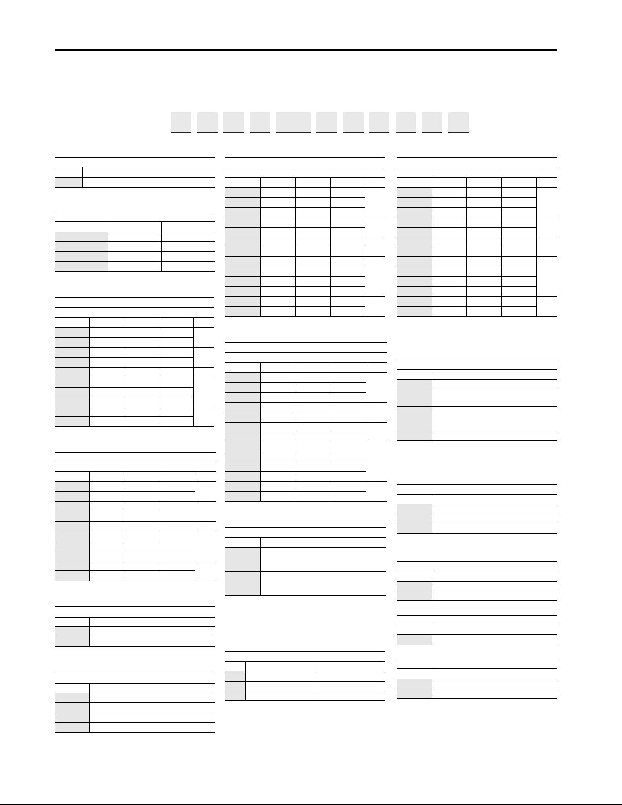
PowerFlex 70 Adjustable Frequency AC Drive
a
b
c1
c2
h
j
c3
c4
i
k
c5
d
e
f
g
l
Drive
Code Type
20 A PowerFlex 70
Volt age Rati ng
Code Voltage Ph.
B 240V AC 3 (six pulse)
C 400V AC 3 (six pulse)
D 480V AC 3 (six pulse)
E 600V AC 3 (six pulse)
PowerFlex 70 ND Rating
208V, 60 Hz Input
Code 208V amps kW Hp Frame
2P2 2.5 0.37 0.5
A
4P2 4.8 0.75 1.0
6P8 7.8 1.5 2.0
B
9P6 11 2.2 3.0
015 17.5 4.0 5.0 C
022 25.3 5.5 7.5
D
028 32.2 7.5 10
042431115
054561520
E
070 78.2 18.5 25
PowerFlex 70 ND Rating
240V, 60 Hz Input
Code Am ps kW Hp Frame
2P2 2.2 0.37 0.5
A
4P2 4.2 0.75 1.0
6P8 6.8 1.5 2.0
B
9P6 9.6 2.2 3.0
015 15.3 4.0 5.0 C
022 22 5.5 7.5
D
028 28 7.5 10
042 42 11 15
054 54 15 20
E
070 70 18.5 25
Internal Brake Resistor
Code w/ Resistor
YYes
NNo
Comm Slot
Code Network Type
C ControlNet (Coax)
D DeviceNet
E EtherNet/IP
NNone
PowerFlex 70 ND Rating
400V, 50 Hz Input
Code Amps kW Hp Fram e
1P3 1.3 0.37 0.5
A
2P1 2.1 0.75 1.0
3P5 3.5 1.5 2.0
5P0 5.0 2.2 3.0
B
8P7 8.7 4.0 5.0
011 11.5 5.5 7.5
C
015 15.4 7.5 10
022 22 11 15
D
030 30 15 20
037 37 18.5 25
043 42 22 30
060 60 30 40
E
072 72 37 50
PowerFle x 70 ND Rat ing
480V, 50 Hz Input
Code Amps kW H p F rame
1P1 1.1 0.37 0.5
A
2P1 2.1 0.75 1.0
3P4 3.4 1.5 2.0
5P0 5.0 2.2 3.0
B
8P0 8.0 3.7 5.0
011 11 5.5 7.5
C
014 14 7.5 10
022 22 11 15
D
027 27 15 20
034 34 18.5 25
040 40 22 30
052 52 30 40
E
065 65 37 50
Emission Class
Code R ating
A
Filtered
(1)
A
(2)
& B Frames (Optional)
C, D, & E Frames (Standard)
(1) 600V Frames A…D available only without filter (Cat. Code N). 600V
Frame E available with filter (Cat. Code A).
(2) Increases size to Frame B.
N
Not Filtered
(1)
A & B Frames (Optional)
C, D, & E Frames (Standard)
Control a nd I/O
Code Control Safe Torque Off
N
(1)
(1) No longer available for sale.
Standard —
CEnhanced No
GEnhanced Yes
PowerFle x 70 ND R ating
600V, 60 Hz Input
(1)
(1) 600V class drives are declared to meet the Low Voltage Directive. It is
the responsibility of th e user to determine compliance to the EMC
Directive.
Code A mps kW H p Fra me
0P9 0.9 0.37 0.5
A
1P7 1.7 0.75 1.0
2P7 2.7 1.5 2.0
3P9 3.9 2.2 3.0
B
6P1 6.1 4.0 5.0
9P0 9.0 5.5 7.5
C
011 11 7.5 10
017171115
D
022221520
027 27 18.5 25
032322230
041413040
E
052523750
Enclosure
Code Enclosure
A
(1)
(1) IP20 and IP66 frame E drives are manufactured with a flange-like
heat sink with mounting holes.
Panel Mount - IP 20, NEMA/UL Type 1
C
(1)
Wall/Machine Mount = IP66, NEMA/UL Type 4X/12 for
indoor use only
F
Flange Mount - Front Chassis = IP 20, NEMA/UL Type 1;
Rear Heat sink = IP66, NEMA/UL Type 4X/12 for indoor
use only
G Wall/Machine Mount - IP54, NEMA/UL Type 12
(2)
(2) Only available on Frame E.
HIM
Code Interface Module
0Blank Cover
3 Full Numeric LCD
5Prog. Only LCD
(1)
(1) Only available with NEMA 4X, enclosure C.
Documentation
Code Type
AManual
NNo manual
Brake IGBT
Code w/Brake
YYes
Feedback
(1)
(1) Drive is not CE EMC certifie d when the encoder interface option is
installed.
Code Feedback
0 No Feedback - Enhanced Control
1 5V/12V Encoder w/Enhanced Control
1…3 4 5…7 8 9 10 11 12 13 14 15 16
20A
B
2P2 A 3 A Y Y N N C 0
Catalog Number Explanation
abcde ghif jkl
4 Rockwell Automation Publication 20A-IN009F-EN-P - April 2018
Page 5
Step 1: Read the Precautions and General Information
Qualified Personnel
ATTENTION: Only qualified personnel familiar with adjustable frequency AC drives and associated machinery can plan or implement the installation, startup,
and subsequent maintenance of the system. Failure to comply can result in personal injury and/or equipment damage.
Personal Safety
ATT EN TIO N: To avoid an electric shock hazard, verify that the voltage on the bus capacitors has discharged before per forming any work on the drive. Measure
the DC bus voltage at the +DC terminal of the Power Terminal Block and the -DC test point (refer to Frame A, B, C, D Power Terminal Block, and DC Bus Test
Point s on page 19 for location). The voltage must be zero.
ATT EN TIO N: Risk of injury or equipment damage exists. DPI™ or SCANport™ host products must not be directly connected together via 1202 cables.
Unpredictable behavior can result if two or more devices are connected in this manner.
ATT EN TIO N: The drive start/stop/enable control circuitry includes solid-state components. If hazards due to accidental contact with moving machinery or
unintentional flow of liquid, gas or solids exist, an additional hard-wired stop circuit may be required to remove the AC line to the drive. An auxiliary braking
method may be required.
PowerFlex 70 Adjustable Frequency AC Drive
Product Safety
ATT EN TIO N: An incorrectly applied or installed drive can result in component damage or a reduction in product life. Wiring or application errors, such as,
undersizing the motor, incorrect or inadequate AC supply, or excessive ambient temperatures can result in malfunction of the system.
ATT EN TIO N: This drive contains ESD (Electrostatic Discharge) sensitive parts and assemblies. Static control precautions are required when installing, testing,
servicing, or repairing this assembly. Component damage can result if ESD control procedures are not followed. If you are not familiar with static control
procedures, reference Guarding Against Electrostatic Damage, publication 8000-4.5.2 or any other applicable ESD protection handbook.
ATT EN TIO N: Configuring an analog input for 0…20 mA operation and driving it from a voltage source could cause component damage. Verify proper
configuration before applying input signals.
ATT EN TIO N: A contactor or other device that routinely disconnects and reapplies the AC line to the drive to start and stop the motor can cause drive hardware
damage. The drive is designed to use control input signals that start and stop the motor. If an input device is used, operation must not exceed 1 cycle per minute
or drive damage can occur.
ATT EN TIO N: The “adjust freq” por tion of the bus regulator function is useful for preventing nuisance overvoltage faults that result from aggressive
decelerations, overhauling loads, and eccentric loads. It forces the output frequency to be greater than commanded frequency while the drive’s bus voltage is
increasing towards levels that can cause a fault; however, it can also cause either of the following two conditions to occur.
• Fast positive changes in input voltage (more than a 10% increase within 6 minutes) can cause uncommanded positive speed changes; however an F25
“OverSpeed Limit” fault occurs if the speed reaches P82 [Max Speed] + P83 [Overspeed Limit]. If this condition is unacceptable, take theses actions;
1) limit supply voltages within the specification of the drive and,
2) limit fast positive input voltage changes to less than 10%. Without taking such actions, if this operation is unacceptable, the “adjust freq” por tion of the
bus regulator function must be disabled (see parameters 161 [Bus Reg Mode A] and 162 [Bus Reg Mode B]).
• Actual deceleration times can be longer than commanded deceleration times; however, a “Decel Inhibit” fault is generated if the drive stops decelerating
altogether. If this condition is unacceptable, the “adjust freq” portion of the bus regulator must be disabled (see parameters 161 [Bus Reg Mode A] and 162
[Bus Reg Mode B]). In addition, installing a properly sized dynamic brake resistor provides equal or better performance in most cases.
Note: These faults are not instantaneous and have shown test results that take 2...12 seconds to occur.
Rockwell Automation Publication 20A-IN009F-EN-P - April 2018 5
Page 6

PowerFlex 70 Adjustable Frequency AC Drive
Output Contactor Precaution
ATT EN TI ON : To guard against drive damage when using output contactors, the following information must be read and understood. One or more output
contactors can be installed between the drive and motors for disconnecting or isolating certain motors/loads. If a contactor is opened while the drive is
operating, power is removed from the respective motor, but the drive continues to produce voltage at the output terminals. In addition, reconnecting a motor
to an active drive (by closing the contactor) could produce excessive current that can cause the drive to fault. If any of these conditions are determined to be
undesirable or unsafe, wire an auxiliary contact on the output contactor to a drive digital input that is programmed as “Enable.” With the drive Enable input
that is wired to the output contactor, the drive can coast-to-stop (cease output) whenever the output contactor is opened.
EMC Instructions
The following section provides instructions for Electromagnetic Compatibility (EMC) compliance.
CE Conformity
Conformity with the Low Voltage (LV) and EMC Directive has been demonstrated by using harmonized European Norm (EN) standards that are
published in the Official Journal of the European Communities. PowerFlex Drives comply with the EN standards that are listed when installed
according to the user manuals and reference manuals.
CE declarations of conformity are available online at:
http://www.rockwellautomation.com/rockwellautomation/certification/overview.page
(1)
Low Voltage Directive (2014/35/EU)
• EN61800-5-1, electronic equipment for use in power installations.
EMC Directive (2014/30/EU)
• EN61800-3, adjustable speed electrical power drive systems Part 3: EMC product standard including specific test methods.
General Notes
• Some drives are equipped with an adhesive label on the top of the drive. If the adhesive label is removed, the drive must be installed in an
enclosure with side openings less than 12.5 mm (0.5 in.) and top openings less than 1.0 mm (0.04 in.) to maintain compliance with the LV
directive.
• Use a motor cable that is as short as possible to avoid electromagnetic emission and capacitive currents.
• Do not use line filters in ungrounded systems.
• PowerFlex drives can cause radio interference if used in a residential or domestic environment. Follow national and local industrial safety
regulations and/or electrical codes, in addition to the essential requirements for CE compliance (see page 7
• Conformity of the drive with CE EMC requirements does not mean that an entire machine or installation complies with CE EMC
requirements. Many factors can influence total machine/installation compliance.
• PowerFlex drives can generate conducted low-frequency disturbances (harmonic emissions) on the AC supply system. More information
regarding harmonic emissions can be found in the PowerFlex 70 EC and 700 VC Reference Manual, publication PFLEX-RM004.
), to prevent radio interference.
(1) CE certification testing has not been completed for 600V class drives.
6 Rockwell Automation Publication 20A-IN009F-EN-P - April 2018
Page 7
PowerFlex 70 Adjustable Frequency AC Drive
B Frame
E Frame
Install One Ferrite
Core on the I/O Cable
for B Frame Drives
Install Three Ferrite
Cores on the I/O Cable
for E Frame Drives
Essential Requirements for CE Compliance
These eight conditions must be satisfied for PowerFlex drives to meet the requirements of EN61800-3:
• Standard PowerFlex 70 CE compatible drive.
• Review important precautions/attention statements throughout this manual before installing the drive.
• The drive installation cannot include the encoder interface option
(20A-ENC-1, drive catalog number, position 16 must be 0. For example: 20Axxxxxxxxxxxx0).
• Ground the drive as described in General Grounding Requirements on page 19.
• Output power, control (I/O), and signal wiring must be braided, shielded cable with a coverage of 75% or better, metal conduit or
equivalent attenuation.
• For B and E frame drives only, ferrite core kit (20A-EMC01) must be installed on the I/O cable, as close to the drive as possible, per Ferrite
Core Installation on B Frame and E Frame Drives Only.
Ferrite Core Installation on B Frame and E Frame Drives Only
• All shielded cables must terminate with the proper shielded connector
• Comply with the conditions in PowerFlex 70 EN61800-3 EMC Compatibility
on page 8.
Rockwell Automation Publication 20A-IN009F-EN-P - April 2018 7
Page 8
PowerFlex 70 Adjustable Frequency AC Drive
76.2 mm
(3.0 in.)
76.2 mm
(3.0 in.)
76.2 mm
(3.0 in.)
76.2 mm
(3.0 in.)
PowerFlex 70 EN61800-3 EMC Compatibility
Second Environment
Frame Drive Description
Drive only X X
A
B
C, D, E
(1) Input cables through a Ferrite Core (frames A, B, and C Fair-Rite #2643102002 or equivalent, frames D and E Fair-Rite #2643251002 or equivalent).
With any comm option X X
With remote I/O X X X
Drive only X X
With any comm option X X
With remote I/O X X X
Drive only X
With any comm option X
With remote I/O X X
Restrict Motor
Cable to 40 m
(131 ft)
Internal
Filter
Option
External
Filter
Input Ferrite
(1)
First
Environment
Restricted
Distribution
See PowerFlex
Reference Manual,
publication
PFLEX-RM001
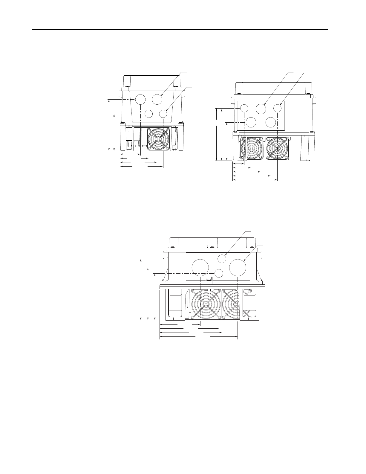
Step 2: Mount the Drive – Minimum Requirements
This section describes the minimum requirements to mount the drive.
Minimum Mounting Clearances
Specified vertical clearance requirements are intended to be from the drive to the closest object that can
restrict airflow through the drive heat sink and chassis. The drive must be mounted in a vertical orientation
as shown, and must make full contact with the mounting surface. Do not use standoffs or spacers. In
addition, inlet air temperature must not exceed the product specification.
Maximum Surrounding Air Temperature
Enclosure Rating Temperature Range
Open Type, IP 20, NEMA/UL Type 1 and flange mount 0…50 °C (32…122 °F)
IP54 and IP66 NEMA/UL Type 4X/12 0…40 °C (32…104 °F)
ATT EN TI ON : Some drives are equipped with an adhesive label on the top of the chassis. Removing
the adhesive label from the drive changes the NEMA/UL enclosure rating from Type 1 Enclosed to
Open Type.
8 Rockwell Automation Publication 20A-IN009F-EN-P - April 2018
Page 9

PowerFlex 70 Adjustable Frequency AC Drive
Power Ratings, Dimensions, and Approximate Weights
This section provides power ratings, dimensions, and weights for the drives.
Power Ratings
Output Power Frame Size
kW
ND (HD)
Hp
ND (HD)
Not
Filtered
0.37 (0.25) 0.5 (0.33) A B B A B B A – B
0.75 (0.55) 1 (0.75) A B B A B B A – B
1.5 (1.1) 2 (1.5) B B B A B B A – B
2.2 (1.5) 3 (2) B B B B B B B – B
4 (3) 5 (3) – C D B B B B – B
5.5 (4) 7.5 (5) – D D – C D C – D
7.5 (5.5) 10 (7.5) – D D – C D C – D
11 (7.5) 15 (10) – D D – D D D – D
15 (11) 20 (15) – E E – D D D – D
18.5 (15) 25 (20) – E E – D D D – D
22 (18.5) 30 (25) – – – – D D D – D
30 (22) 40 (30) – – – – E E – E E
37 (30) 50 (40) – – – – E E – E E
(1) Not filtered is indicated if positi on 13 of the catalog number = N.
(2) Filtered is indicated if position 13 of the catalog number = A.
(3) For indoor use only.
208…240V AC Input 400…480V AC Input 600V AC Input
(1)
Type 4X/12
IP66 NEMA/UL
(2)
Filtered
(3)
Not Filtered
(1)
Filtered
(2)
IP66 NEMA/UL
Type 4X/12
(3)
Not Filtered
(1)
Filtered
(2)
IP66 NEMA/UL
Type 4X/12
(3)
Rockwell Automation Publication 20A-IN009F-EN-P - April 2018 9
Page 10
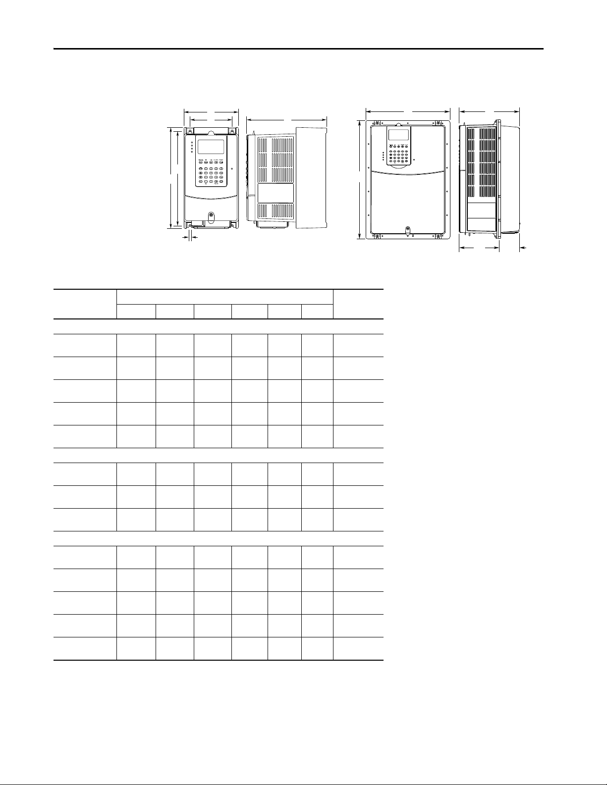
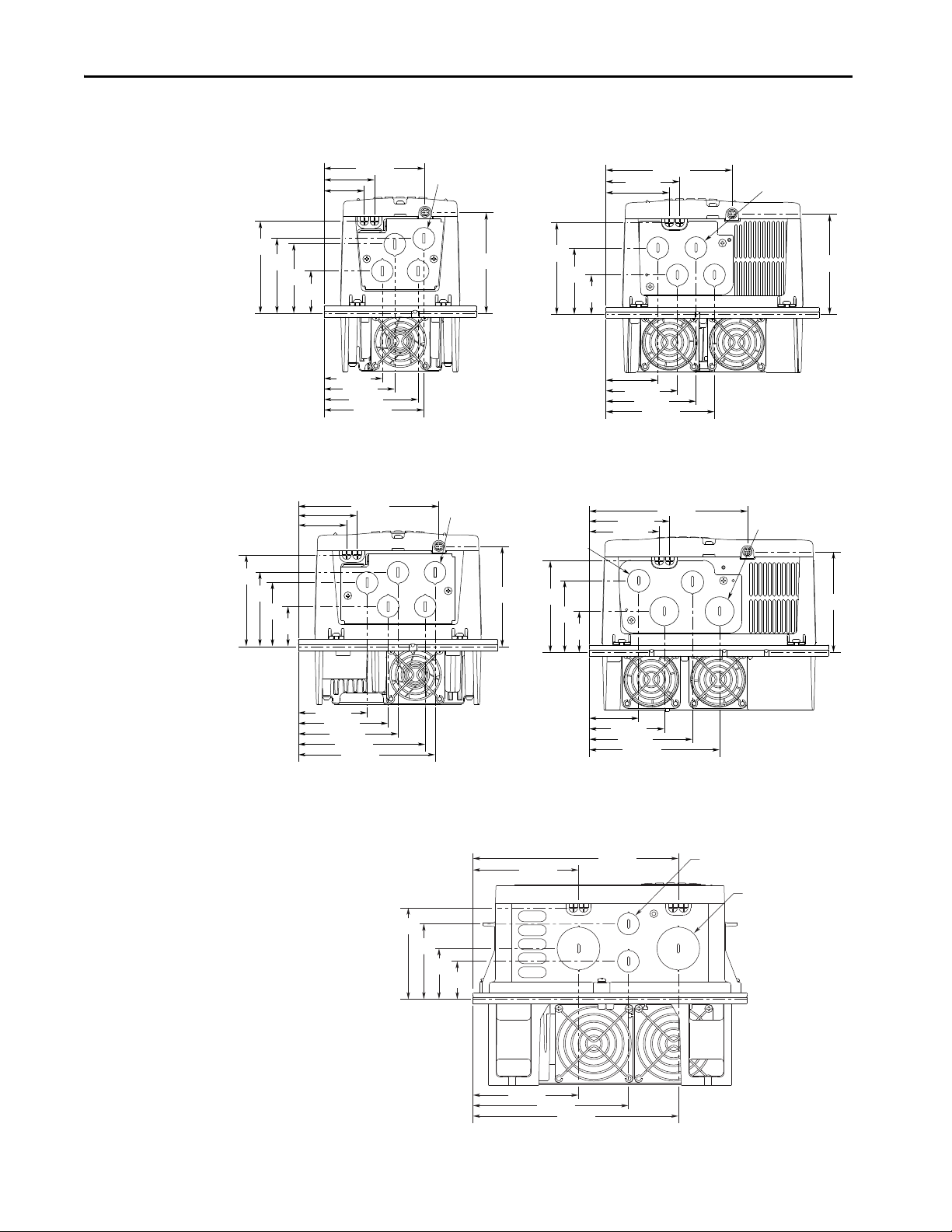
PowerFlex 70 Adjustable Frequency AC Drive
IP20 and IP66 NEMA/UL Type 1 and 4X/12 Flange Mount
E
B
D
C
Dimension Drawings
A
F
Dimensions and Approximate Weights
Frame
A 122.4 (4.82) 225.7 (8.89) 179.8 (7.08) 94.2 (3.71)
B 171.7 (6.76) 234.6 (9.24) 179.8 (7.08)
C 185.0 (7 .28)
D 219.9 (8.66)
(1)
E
B 171.7 (6.76) 239.8 (9.44) 203.3 (8.00)
D 219.9 (8.66)
(1)(2)
E
A 156.0 (6.14) 225.8 (8.89) 178.6 (7.03)
B 205.2 (8.08) 234.6 (9.24) 178.6 (7.03)
C 219.0 (8 .62)
D 248.4 (9.78)
E
(1) IP20 and IP66 frame E drives are manufactured with a flange-like heat sink with mounting holes.
(2) Frame E is also available in IP54 NEMA/UL Type 12 as a wall/machine mount.
(3) Approximate weights include the HIM.
ABCDEF
IP20 NEMA/UL Type 1
300.0
(11.81)
350.0
(13.78)
280.3
(11.04)
IP66 NEMA/UL Type 4X/12 (for Indoor Use Only)
280.3
(11.04)
Flange Moun t
280.3
(11.04)
555.8
(21.88)
350.0
(13.78)
555.8
(21.88)
300.0
(11.81)
350.0
(13.78)
555.8
(21.88)
Dimensions, mm (in.)
122.7
(4.83)
179.8 (7.08)
179.8 (7.08)
207.1 (8.15)
210.7 (8.29)
219.8 (8.65)
178.6 (7.03)
178.6 (7.03)
207.1 (8.15)
137.6
(5.42)
169.0
(6.65)
200.0
(7.87)
122.7
(4.83)
169.0
(6.65)
200.0
(7.87)
123.0
(4.84)
123.0
(4.84)
123.0
(4.84)
123.0
(4.84)
117.2
(4.61)
211.6
(8.33)
220.2
(8.67)
285.6
(11.25)
335.6
(13.21)
491.0
(19.33)
220.2
(8.67)
335.6
(13.21)
491.0
(19.33)
55.6
(2.19)
55.6
(2.19)
55.6
(2.19)
55.6
(2.19)
89.9
(3.54)
B
Weight
kg (lb)
5.8 (0.23) 2.71 (6.0)
5.8 (0.23) 3.60 (7.9)
5.8 (0.23) 6.89 (15.2)
5.8 (0.23) 9.25 (20.4)
6.9 (0.27) 18.60 (41.0)
5.8 (0.23) 3.61 (8.0)
5.8 (0.23) 9.13 (20.1)
6.9 (0.27) 18.60 (41.0)
– 2.71 (6.0)
– 3.60 (7.9)
– 6.89 (15.2)
– 9.25 (20.4)
– 18.60 (41.0)
A
C
D E
(3)
10 Rockwell Automation Publication 20A-IN009F-EN-P - April 2018
Page 11
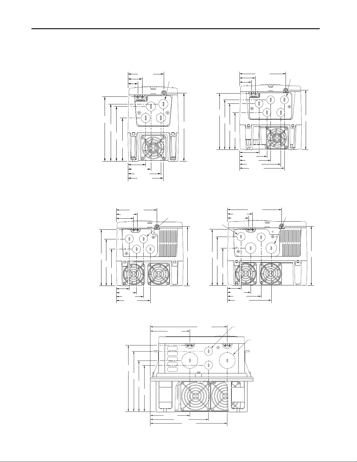
Frame A
(For some drive ratings, the fan is not present.)
Frame B
Frame DFrame C
Frame E
42.7 (1.68)
55.4 (2.18)
79.3 (3.12)
85.1 (3.35)
23.9 (0.94)
34.5 (1.36)
4 Places
102.4
(4.03)
129.8
(5.11)
135.9
(5.35)
163.7
(6.45)
55.6 (2.19)
75.5 (2.97)
85.7 (3.37)
113.5 (4.47)
123.8 (4.87)
127.5 (5.02)
43.4 (1.71)
32.8 (1.29)
101.6
(4.00)
126.2
(4.97)
136.7
(5.38)
155.2
(6.11)
163.7
(6.45)
22.2 (0.87) Dia.
5 Places
36.1 (1.42)
56.1 (2.21)
75.2 (2.96)
94.2 (3.71)
47.7 (1.88)
58.4 (2.30)
112.3 (4.42)
101.3
(3.99)
129.3
(5.09)
155.2
(6.11)
163.5
(6.44)
22.2 (0.87) Dia.
4 Places
37.5 (1.48)
64.0 (2.52)
93.0 (3.66)
121.0 (4.76)
149.7 (5.89)
69.3 (2.73)
58.6 (2.31)
103.2
(4.06)
134.7
(5.30)
155.2
(6.11)
164.1
(6.46)
28.5 (1.12) Dia.
2 Places
22.2 (0.87) Dia.
2 Places
108.0 (4.25)
159.0 (6.26)
210.0 (8.27)
126.9
(4.99)
139.9
(5.50)
210.0 (8.27)
108.0 (4.25)
(0.87)
43.7
165.0
(6.49)
RAS Rockwell Automation Support
PowerFlex 70 IP20 NEMA/UL Type 1 Bottom View Dimensions, mm (in.)
PowerFlex 70 Adjustable Frequency AC Drive
155.2
(6.11)
86.4 (3.40)
22.2 (0.87) Dia.
22.2
(1.72)
181.5
(7.14)
Rockwell Automation Publication 20A-IN009F-EN-P - April 2018 11
Page 12
PowerFlex 70 Adjustable Frequency AC Drive
Frame B Frame D
55.2 (2.17)
77.3 (3.04)
99.6 (3.92)
99.6
(3.92)
(1.11)
22.1
31.0 (1.22)
49.1 (1.93)
75.5 (2.97)
102.0 (4.02)
102.9
(4.05)
138.6
(5.46)
(1.11)
Frame E
108.2 (4.26)
157.7 (6.21)
165.7 (6.52)
207.7 (8.18)
22.5
(0.89)
44.5
(1.75)
124.9
(4.92)
139.9
(5.51)
163.4
(6.43)
PowerFlex 70 IP 66 NEMA/UL Type 4X/12 Bottom View Dimensions, mm (in.)
(for indoor use only)
28.3
(0.87)
138.2
(5.44)
115.9 (4.56)
PowerFlex 70 IP 54 / IP 66 NEMA/UL Type 4X/12 Bottom View Dimensions, mm (in.)
140.5
(5.53)
120.1 (4.73)
28.3
22.1
(0.87)
12 Rockwell Automation Publication 20A-IN009F-EN-P - April 2018
Page 13
PowerFlex 70 Flange Mount Bottom View Dimensions, mm (in.)
Frame A
Frame B Frame D
Frame C
Frame E
72.4 (2.85)
59.6 (2.35)
96.1 (3.78)
101.9 (4.01)
40.7 (1.60)
51.3 (2.02)
22.2 (0.87) Dia.
4 Places
43.2
(1.70)
70.5
(2.78)
76.6
(3.02)
95.9
53.1 (2.09)
73.0 (2.87)
92.2 (3.63)
111.2 (4.38)
64.7 (2.55)
75.4 (2.97)
129.3 (5.09)
40.6
(1.60)
68.7
(2.70)
94.6
(3.72)
102.9
(4.05)
22.2 (0.87) Dia.
4 Places
70.9 (2.79)
92.4 (3.64)
102.7 (4.04)
130.5 (5.14)
140.6 (5.54)
60.3 (2.37)
49.7 (1.96)
41.4
(1.63)
65.9
(2.59)
76.6
(3.02)
95.0
5 Places
51.9 (2.04)
78.3 (3.08)
107.3 (4.22)
135.5 (5.33)
164.1 (6.46)
83.7 (3.30)
73.0 (2.87)
42.3
(1.67)
74.1
(2.92)
94.6
(3.27)
103.5
(4.07)
28.5 (1.12) Dia.
2 Places
22.2 (0.87) Dia.
2 Places
108.0 (4.25)
159.0 (6.26)
210.0 (8.27)
39.8
(1.57)
52.8
(2.08)
94.4
210.0 (8.27)
108.0 (4.25)
(0.87)
43.7
77.9
(3.07)
103.2 (4.06)
PowerFlex 70 Adjustable Frequency AC Drive
(3.78)
144.4 (5.69)
(3.74)
104.4
(4.11)
22.2 (0.87) Dia.
103.5
(4.07)
22.2
(1.72)
(3.72)
Rockwell Automation Publication 20A-IN009F-EN-P - April 2018 13
Page 14
PowerFlex 70 Adjustable Frequency AC Drive
Frame A Frame B
Frame C
Frame D Frame E
127,0
(5.00)
197.9
(7.80)
(6.14)
6,9
140,7
(5.54)
70,7
(2.78)
210,6
(8.29)
105,3
(4.15)
5.0
(0.20)
8x: Ø3,5
(Ø0.14)
4x: 3,0R
(0.12R)
58,8
(2.31)
176,3
(6.94)
205,5
(8.09)
(8.08)
6,9
190,0
(7.48)
95,0
(3.74)
219,3
(8.63)
109,7
(4.32)
6,9
(0.27)
8x: Ø3,5
(Ø0.14)
4x: 3,0R
(0.12R)
58,8
(2.31)
189,4
(7.46)
272,3
(10.72)
(8.62)
6,3
(0.25)
202,0
(7.95)
101,0
(3.98)
283,0
(11.14)
300,0
41,5
(1.63)
141,5
(5.57)
241,5
(9.51)
5,1
(0.20)
12x: Ø3,5
(Ø0.14)
4x: 3,0R
(0.12R)
58,8
(2.31)
222,4
(8.76)
321,4
(12.65)
248,4
(9.78)
4,5
(0.18)
115,7
(4.56)
190,7
(7.51)
231,4
(9.11)
40,7
(1.60)
333,0
(13.11)
350,0
(13.78)
61,5
(2.42)
201,5
(7.93)
131,5
(5.18)
271,5
(10.69)
4,5
(0.18)
14x: Ø3,5
(Ø0.14)
4x: 3,0R
(0.12R)
58,8
(2.31)
250.4
(9.86)
525.8
(20.70)
(11.04)
6.0
131.2
(5.16)
206.2
(8.12)
262.4
(10.33)
56.2
(2.21)
493.9
(19.44)
555.8
193.9
(7.63)
118.9
(4.68)
43.9
(1.73)
343.9
(13.54)
268.9
(10.59)
418.9
(16.49)
6.0
(0.24)
20x: Ø3.5
(Ø0.14)
87.1
(3.43)
PowerFlex 70 Cutout Dimensions
156,0
(0.27)
225,8
(8.89)
(0.27)
205,2
234,6
(9.24)
219,0
(11.81)
280.3
(0.24)
(21.88)
14 Rockwell Automation Publication 20A-IN009F-EN-P - April 2018
Page 15
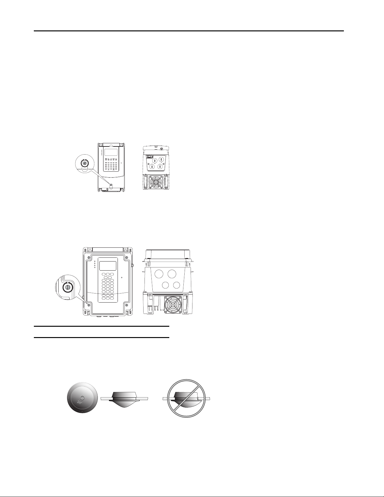
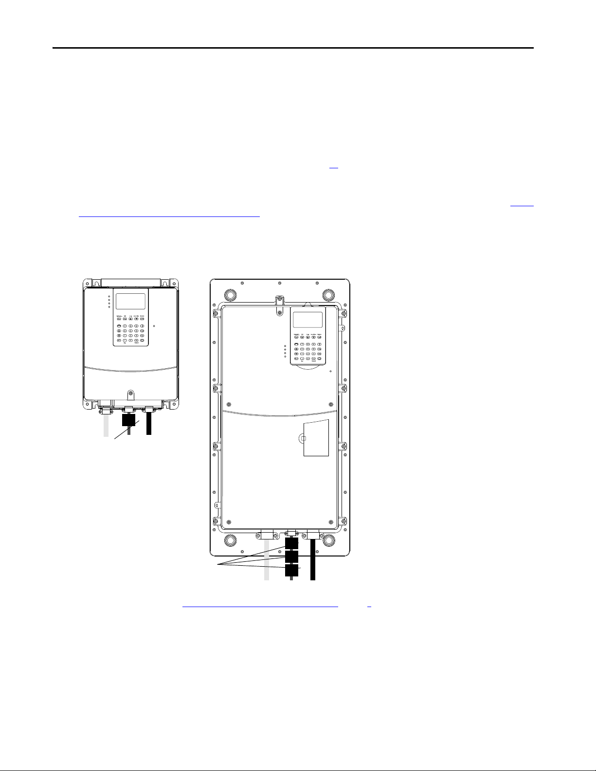
Step 3: Wire the Drive – Wire Recommendations
1. Loosen the cover screw. 2. Pull the cover straight off the chassis to
avoid damaging the connector pins.
1. Loosen the cover screws. 2. Pull the cover straight off the chassis.
This section describes wiring recommendations for the drive.
Opening the Cover
To open the cover, follow the steps for your drive enclosure that is shown.
IP20 NEMA/UL Type 1
PowerFlex 70 Adjustable Frequency AC Drive
IP66 NEMA/UL Type 4X/12 (for Indoor Use Only)
IMPORTANT Torque cover screws to 0.79 N•m (7 lb•in).
IP66 NEMA/UL Type 4X/12 Indoor Installations
Use the plugs that are supplied with IP66 NEMA/UL Type 4X/12 rated drives to seal unused holes in the conduit entry plate.
For the best seal, be sure that the inner rim of the plug is fully seated against the edge of the conduit entry hole.
Rockwell Automation Publication 20A-IN009F-EN-P - April 2018 15
Page 16
PowerFlex 70 Adjustable Frequency AC Drive
Wiring Specifications
Type Wire Types Description Min Insulation Rating
600V, 90 °C (194 °F)
Power
(1)(2)
Signal
(1) (3) (4)
Digital I/O
(1) (3) (4)
(1) Control and signal wires must be sep arated from power wires by at least 0.3 m (1 ft).
(2) We recommend the use of shielded wire for AC input power (even if it is not ne cessary).
(3) If the wires are short and contained within a cabinet that has no sensitive circuits, we recommend the use of shielded wire (even if it is not necessary).
(4) I/O terminals that are labeled “(–)” or “Common” are not referenced to earth ground and are designed to greatly reduce common mode interference. Grounding these termina ls can cause signal noise.
Standard
Standard analog I/O
Shielded
XHHW2/RHW-2
Anixter
B209500-B209507, Belden 2950129507 (or equivalent)
Belden 8760/9460 (or equivalent)
Belden 8770 (or equivalent)
Multi-conductor shielded cable such as
Belden 8770 (or equivalent)
Four tinned copper conductors with XLPE
insulation.
Copper braid/aluminum foil combination shield
and tinned copper drain wire.
PVC jacket.
2
0.750 mm
(18 AWG), twi sted-pair, 100% shield
with drain.
2
0.750 mm
(18 AWG), three-conductor,
shielded for remote pot.
2
0.750 mm
(18 AWG), three-conductor,
shielded.
–
300V,
75…90 °C (167…194 °F)
300V,
60 °C (140 °F)
AC Supply Source Considerations
PowerFlex 70 drives are suitable for use on a circuit capable of delivering up to a maximum of 200,000 rms symmetrical amperes, and a maximum of
600V.
ATTENTION: To guard against personal injury and/or equipment damage that is caused by improper fusing or circuit breaker selection, use the recommended
line fuses/circuit breakers that are specified in Drive, Fuse, and Circuit Breaker Ratings on page 22
.
If the drive has a system ground fault monitor (residual current-operated protective device), use Type B (adjustable) devices to avoid nuisance
tripping.
Unbalanced, Ungrounded, High Resistance or B-phase Grounded Distribution Systems
Install an isolation transformer on an ungrounded distribution system where the line-to-ground voltages on any phase could exceed 125% of the
nominal line-to-line voltage. See Wiring and Grounding Guidelines for PWM AC Drives, publication DRIVES-IN001
, for more information on
impedance grounded and ungrounded systems.
Input Power Conditioning
Some events on the power system supplying a drive can cause component damage or shortened product life. These events are divided into two basic
categories that are described:
• All Drives
– The power system has power factor correction capacitors that are switched in and out of the system, either by the user or by the power
company.
– The power source has intermittent voltage spikes in excess of 6000V. These spikes could be caused by other equipment on the line, or by
events such as lightning strikes.
– The power source has frequent interruptions.
• 5 Hp or Less Drives (in addition to all drives above)
– The nearest supply transformer is larger than 100 kVA, or the available short circuit (fault) current is greater than 100,000 A.
– The impedance in front of the drive is less than 0.5%.
If any or all of these conditions exist, we recommend that you install a minimum amount of impedance between the drive and the source. This
impedance could come from the supply transformer itself, the cable between the transformer and drive, or an additional transformer or reactor. To
calculate the impedance, use the information that is supplied in the Wiring and Grounding Guidelines for Pulse Width Modulated (PWM) AC
Drives, publication DRIVES-IN001
.
16 Rockwell Automation Publication 20A-IN009F-EN-P - April 2018
Page 17
PowerFlex 70 Adjustable Frequency AC Drive
IP 20 (NEMA/UL Type 1)
IP 66 (NEMA/UL Type 4X/12)
Single-phase Input Power
The PowerFlex 70 drive is typically used with a three-phase input supply. Underwriters Laboratories (UL) lists the drive to operate on single-phase
input power. Single-phase operation provides 50% of the three-phase rated current. See 208/240 Volt AC Single-phase Input Drive Ratings and
Input Protection Devices on page 24 through 600 Volt AC Single-phase Input Drive Ratings and Input Protection Devices on page 26.
Generator Input Power
Contact technical support for details on how to power a drive properly when using generator power. See Rockwell Automation Support on the back
cover.
Power Terminal Block
Typical Power Terminal Block Location (B frame shown)
Rockwell Automation Publication 20A-IN009F-EN-P - April 2018 17
Page 18

PowerFlex 70 Adjustable Frequency AC Drive
Power Terminal Block Specifications
Wire Size Range
No. Name Frame Description
➊
Power terminal block
➋
SHLD terminal All
(1) Maximum/minimum sizes that the terminal blo ck can accept – these are not recommendations.
A, B, C
D
E
Input power and motor
connections
Input power and motor
connections
Input power and motor
connections
Terminating point for
wiring shields
Max
mm
4.0 (10) 0.3 (22) 1.1 (10) 0.8 (7)
10.0 (6) 0.8 (18) 1.7 (15) 1.4 (12)
25.0 (3) 2.5 (14) 2.71 (24) 2.71 (24)
— — 1.6 (14) 1.6 (14)
2
(AWG)
(1)
Min
2
mm
(AWG)
Tor que
Max
N•m (lb•in)
Recommended
N•m (lb•in)
Wire Routing Recommendations
No. Description
Suggested entry for incoming line wiring.
➌
Suggested entry for motor wiring.
➍
Cable Entry Plate Removal
If more wiring access is needed, the cable entry plate on all drive frames can be removed. Loosen the screws that secure the plate to the heat sink and
slide out the plate.
18 Rockwell Automation Publication 20A-IN009F-EN-P - April 2018
Page 19

Frame A, B, C, D Power Terminal Block, and DC Bus Test Points
L1RL2SL3TBR1
+DC
BR2
BRKT1UT2VT3W
PE PE
-DC
-DC
➊
L1RL2SL3T+DC –DC BR1 BR2 T1UT2VT3
W
PE
M6
L1RL2SL3TBR1
+DC
BR2
BRKT1UT2VT3W
PE PE
-DC
-DC
L1RL2SL3
T
Frame E Power Terminal Block
PE
M6
Terminal Description Notes
RR (L1)
SS (L2)
TT (L3)
BR1 DC brake DB resistor connection - Important: Do not connect both an internal and external
BR2 DC brake
UU (T1) To the motor
VV (T2) To the motor
WW (T3) To the motor
PE PE ground –
PE PE ground –
-DC DC bus (–)
+DC DC bus (+) –
Three-phase AC line input power.
For single-phase input, connect to any two terminals.
DB resistor simultaneously. Doing this can violate the minimum allowed DB
resistance and cause damage to the drive.
➊Test point on Frames A, B, C, and D are to the left or right of the power terminal
block. Frame E has a dedicated terminal.
PowerFlex 70 Adjustable Frequency AC Drive
Power Input Terminals on Frame B with Internal RFI Filter Option
General Grounding Requirements
IMPORTANT The safety ground for the drive (PE) must be connected to system ground.
Ground impedance must conform to the requirements of national and local industrial safety regulations and/or electrical codes. Check the integrity
of all ground connections periodically.
For installations within a cabinet, one safety ground point or ground bus bar connected directly to building steel (girder, joist) can be used. All
circuits including the AC input ground conductor can be grounded independently and directly to this point/bar.
Rockwell Automation Publication 20A-IN009F-EN-P - April 2018 19
Page 20
PowerFlex 70 Adjustable Frequency AC Drive
U (T1)
V (T2)
W (T3)
R (L1)
S (L2)
T (L3)
PE
SHLD
Typical Grounding
Safety Ground (PE)
The safety ground for the drive is required by code. This point must be connected to adjacent building steel (girder, joist), a floor ground rod, or bus
bar (see Typical Grounding). Grounding points must comply with national and local industrial safety regulations and/or electrical codes.
Shield Termination - SHLD
The shield terminal (see Typical Power Terminal Block Location (B frame shown) on page 17) provides a grounding point for the motor cable
shield. The motor cable shield can be connected to this terminal on the drive (on the drive end) and the motor frame (on the motor end). A shield
terminating cable gland can also be used.
If you use shielded cable for control and signal wiring, the shield can be grounded at the source end, and not the drive end.
RFI Filter Grounding
IMPORTANT Use RFI filters only in inst allations with grounded AC supply systems that are permanently installed and solidly grounded (bonded) to
the building power distribution ground.
If you use an optional radio frequency interference (RFI) filter, relatively high ground leakage currents can be present. Be sure that the incoming
supply neutral is solidly connected (bonded) to the same building power distribution ground. Grounding must not rely on flexible cables and must
exclude any form of plug or socket that permits inadvertent disconnection. Some local codes require redundant ground connections. Periodically
check the integrity of all connections. See the instructions that are supplied with the filter
ATT EN TI ON : The PowerFlex 70 does not provide branch short circuit protection. See Drive, Fuse, and Circuit Breaker Ratings on page 22
for the recommended fuse or circuit breaker to protect against short circuits.
.
Power Wiring
ATTENTION: National Codes and standards (NEC, VDE, BSI, and others) and local codes outline provisions for safely installing electrical
equipment. Installation must comply with specifications regarding wire types, conductor sizes, branch circuit protection, and disconnect
devices. Failure to do so can result in personal injury and/or equipment damage.
Cable Types Acceptable for 200…600V Installations
Various cable types are acceptable for drive installations. For many installations, unshielded cable is adequate as long as the cable is separated from
sensitive circuits. As an approximate guide, provide a spacing of 0.3 m (1 ft) for every 10 m (32.8 ft) of length. In all cases, do not use long parallel
runs. Do not use cable with an insulation thickness fewer than 15 mils (0.4 mm/0.015 in.). Use copper wire. Wire gauge requirements and
recommendations are based on 75 °C (167 °F). Do not reduce wire gauge when using higher temperature wire.
20 Rockwell Automation Publication 20A-IN009F-EN-P - April 2018
Page 21
PowerFlex 70 Adjustable Frequency AC Drive
Unshielded
Thermoplastic High Heat-resistant Nylon-coated (THHN), Thermoplastic Heat and Water-resistant Nylon-coated (THWN), or similar wire is
acceptable for drive installation in dry environments as long as adequate free air space and/or conduit fill rate limits are provided. The wire must
have a minimum insulation thickness of 15 mils (0.4 mm/0.015 in.) and cannot have large variations in insulation concentricity.
IMPORTANT Do not use THHN or similarly coated wire in wet areas.
Shielded/Armored Cable
Shielded cable contains the general benefits of multi-conductor cable with the added benefit of a copper braided shield that can contain much of the
noise that is generated by a typical AC Drive. Use shielded cable for installations with sensitive equipment such as weigh scales, capacitive proximity
switches, and other devices that can be affected by electrical noise in the distribution system. Applications with large numbers of drives in a similar
location, imposed EMC regulations, or a high degree of communications/networking are also good candidates for shielded cable.
Shielded cable can also help reduce shaft voltage and induced bearing currents for some applications. In addition, the increased impedance of
shielded cable can help extend the distance that the motor can be from the drive without the addition of motor protective devices, such as
terminator networks. See Reflected Wave in Wiring and Grounding Guidelines for PWM AC Drives, publication DRIVES-IN001
Consider the general specifications of the environment of the installation, including temperature, flexibility, moisture characteristics, and chemical
resistance. In addition, a braided shield can be included and be specified by the cable manufacturer as having coverage of at least 75%. An additional
foil shield can greatly improve noise containment.
A good example of recommended cable is Belden 295xx (xx determines gauge). This cable has four Cross-linked Polyethylene (XLPE) insulated
conductors with a 100% coverage foil and an 85% coverage copper braided shield (with drain wire) surrounded by a Polyvinyl Chloride (PVC)
jacket.
Other types of shielded cable are available, but the use of these types can limit the allowable cable length. For example, some of the newer cables
bundle four conductors of THHN wire and wrap them tightly with a foil shield. This type of construction can greatly increase the cable charging
current that is required and reduce the overall drive performance. Unless specified in the individual distance tables as tested with the drive, these
cables are not recommended and their performance against the lead length limits is not known.
Recommended Shielded Wire
.
Location Rating/Type Description
Standard (option
2)
Class I and II;
Division I and II
Tray rated 600V, 90 °C
(194 °F) RHH/RHW-2
Anixter OLF-7xxxxx or
equivalent
Tray rated 600V, 90 °C
(194 °F) RHH/RHW-2
Anixter 7V-7xxxx-3G or
equivalent
Three tinned copper conductors with XLPE insulation.
5 mil single helical copper tape (25% overlap minimum) with three bare copper
grounds in contact with the shield.
PVC jacket.
Three bare copper conductors with XLPE insulation and impervious corrugated
continuously welded aluminum armor.
Black sunlight resistant PVC jacket overall.
Three copper grounds on #10 AWG and smaller.
ATTENTION: To avoid a possible shock hazard that is caused by induced voltages, unused wires in the conduit must be grounded at both
ends. Also, if a drive sharing a conduit is being serviced or installed, disable all drives that are using that conduit. Disabling all drives helps
minimize the possible shock hazard from cross coupled motor leads.
Motor Cable Lengths
Typically, motor lead lengths less than 30 m (approximately 100 ft) are acceptable. However, if your application requires longer lengths, refer to
Wiring and Grounding Guidelines for Pulse Width Modulated (PWM) AC Drives, publication DRIVES-IN001, for details.
Electronic Motor Overload Protection
Class 10 motor overload protection according to NEC article 430 and motor over-temperature protection according to NEC article 430.126
(A)(2). UL 508C File E59272.
Rockwell Automation Publication 20A-IN009F-EN-P - April 2018 21
Page 22

PowerFlex 70 Adjustable Frequency AC Drive
Drive, Fuse, and Circuit Breaker Ratings
Integral solid-state short circuit protection does not provide branch circuit protection. Branch circuit protection must be provided in accordance
with the National Electric Code (NEC) and any additional local codes, or the equivalent. The tables on the following pages provide drive ratings
(including continuous, 1 minute and 3 seconds) and recommended AC line input fuse and circuit breaker information. Both types of short circuit
protection are acceptable for UL and IEC requirements. Sizes that are listed are the recommended sizes that are based on 40 °C (104 °F) and the
U.S. N.E.C. Other country, state, or local codes may require different ratings.
Fusing
The recommend fuse types are listed. If available current ratings do not match those listed in the tables that are provided, choose the next higher
fuse rating.
• IEC – BS88 (British Standard) Parts 1 & 2, EN60269-1, Parts 1 & 2
• UL – UL Class CC, T, RK1, or J should be used.
Circuit Breakers
The “non-fuse” listings in the following tables include inverse time circuit breakers, instantaneous trip circuit breakers (motor circuit protectors),
and 140M self-protected combination motor controllers. If one of these devices is chosen as the desired protection method, the following
requirements apply:
• IEC – Both types of circuit breakers and 140M self-protected combination motor controllers are acceptable for IEC installations.
• UL – Only inverse time circuit breakers and the specified 140M self-protected combination motor controllers are acceptable for
UL installations.
(1)
, type gG or equivalent should be used.
208/240 Volt AC Three-phase Input Drive Ratings and Input Protection Devices
Hp
Cat.No.
208 Volt AC Input
20AB2P2 A 0.5 0.33 2.9 1.1 2.5 2.7 3.7 6 6 6 10 15 7 140M-C2E-B40 140M-D8E-B40 – 3441
20AB4P2 A 1 0.75 5.6 2 4.8 5.5 7.4 10 10 10 17.5 15 7 140M-C2E-B63 140M-D8E-B63 – 3441
20AB6P8 B 2 1.5 10 3.6 7.8 10.3 13.8 15 15 15 30 30 15 140M-C2E-C10 140M-D8E-C10 140M-F8E-C10 3441
20AB9P6 B 3 2 14 5.1 11 12.1 16.5 20 25 20 40 40 30 140M-C2E-C16 140M-D8E-C16 140M-F8E-C16 3441
20AB015 C 5 3 16 5.8 17.5 19.2 26.6 20 35 20 70 70 30 140M-C2E-C20 140M-D8E-C20 140M-F8E-C20 3441
20AB022 D 7.5 5 23.3 8.3 25.3 27.8 37.9 30 50 30 100 100 30 – 140M-D8E-C25 140M-F8E-C25 5098
20AB028 D 10 7.5 29.8 10.7 32.2 37.9 50.6 40 70 40 125 125 50 – – 140M-F8E-C32 5098
20AB042 D 15 10 39.8 14.3 43 55.5 74 60 100 60 175 175 70 – – 140M-F8E-C45 5098
20AB054 E 20 15 57.5 20.7 62.1 72.4 96.6 80 125 80 200 200 100 – – – –
20AB070 E 25 20 72.3 26.0 78.2 93.1 124 90 175 90 300 300 100 – – – –
240 Volt AC Input
20AB2P2 A 0.5 0.33 2.5 1.1 2.2 2.4 3.3 3 4.5 3 8 15 3 140M-C2E-B25 140M-D8E-B25 – 3441
20AB4P2 A 1 0.75 4.8 2 4.2 4.8 6.4 6 9 6 15 15 7 140M-C2E-B63 140M-D8E-B63 – 3441
20AB6P8 B 2 1.5 8.7 3.6 6.8 9 12 15 15 15 25 25 15 140M-C2E-C10 140M-D8E-C10 140M-F8E-C10 3441
20AB9P6 B 3 2 12.2 5.1 9.6 10.6 14.4 20 20 20 35 35 15 140M-C2E-C16 140M-D8E-C16 140M-F8E-C16 3441
20AB015 C 5 3 13.9 5.8 15.3 17.4 23.2 20 30 20 60 60 30 140M-C2E-C16 140M-D8E-C16 140M-F8E-C16 3441
20AB022 D 7.5 5 19.9 8.3 22 24.4 33 25 45 25 80 80 30 – 140M-D8E-C25 140M-F8E-C25 5098
20AB028 D 10 7.5 25.7 10.7 28 33 44 35 60 35 110 110 50 – – 140M-F8E-C32 5098
20AB042 D 15 10 38.7 16.1 42 46.2 63 50 90 50 150 150 50 – – 140M-F8E-C45 5098
20AB054 E 20 15 49.8 20.7 54 63 84 60 100 60 200 200 100 – – – –
20AB070 E 25 20 64.5 26.8 70 81 108 90 150 90 275 275 100 – – – –
See page 26
Rating
(1)
ND HD Amps kVA Cont. 1 Min. 3 Sec. Min
Frame
for notes.
Input
Ratings
Output Amps
Dual
Element Time
Delay Fuse
(2)
Max
Non-time Delay
Fuse
(3)
Min
Circuit
Breaker
(2)
(3)
Max
Max
(5)
(4)
Motor Circuit
(6)
Protector
(5)
Max
140M Motor Protector with Adjustable Current Range
Available Catalog Numbers
(9)
(7) (8)
Minimum
Enclosure Volume
3)(10)
(in.
(1) Typical designations include, but may not be limited to the following; Parts 1 & 2: AC, AD, BC, BD, CD, DD, ED, EFS, EF, FF, FG, GF, GG, GH.
22 Rockwell Automation Publication 20A-IN009F-EN-P - April 2018
Page 23

PowerFlex 70 Adjustable Frequency AC Drive
400/480 Volt AC Three-phase Input Drive Ratings and Input Protection Devices
Dual
Element Time
Delay Fuse
(2)
Max
Non-time Delay
Fuse
(3)
Min
Circuit
Breaker
(2)
(3)
Max
Max
(5)
(4)
Motor Circuit
(6)
Protector
(5)
Max
140M Motor Protector with Adjustable Current Range
Available Catalog Numbers
(9)
Cat.No.
Hp
Rating
(1)
ND HD Amps kVA Cont. 1 Min. 3 Sec. Min
Frame
Input
Ratings
Output Amps
400 Volt AC Input
20AC1P3 A 0.37 0.25 1.6 1.1 1.3 1.4 1.9 3 3 3 5 15 3 140M-C2E-B16 – – 3441
20AC2P1 A 0.75 0.55 2.5 1.8 2.1 2.4 3.2 4 6 4 8 15 7 140M-C2E-B25 140M-D8E-B25 – 3441
20AC3P5 A 1.5 1.1 4.3 3 3.5 4.5 6 6 6 6 12 15 7 140M-C2E-B63 140M-D8E-B63 – 3441
20AC5P0 B 2.2 1.5 6.5 4.5 5 5.5 7.5 10 10 10 20 20 15 140M-C2E-C10 140M-D8E-C10 140M-F8E-C10 3441
20AC8P7 B 4 3 11.3 7.8 8.7 9.9 13.2 15 17.5 15 30 30 15 140M-C2E-C16 140M-D8E-C16 140M-F8E-C16 3441
20AC011 C 5.5 4 10.5 7.6 11.5 13 17.4 15 25 15 45 40 15 140M-C2E-C16 140M-D8E-C16 140M-F8E-C16 3441
20AC015 C 7.5 5.5 15.1 10.4 15.4 17.2 23.1 20 30 20 60 60 20 140M-C2E-C16 140M-D8E-C16 140M-F8E-C16 3441
20AC022 D 11 7.5 21.9 15.2 22 24.2 33 30 45 30 80 80 30 – 140M-D8E-C25 140M-F8E-C25 5098
20AC030 D 15 11 30.3 21 30 33 45 40 60 40 120 120 50 – – 140M-F8E-C32 5098
20AC037 D 18.5 15 35 24.3 37 45 60 50 80 50 125 140 50 – – 140M-F8E-C45 5098
20AC043 D 22 18.5 40.7 28.2 43 56 74 60 90 60 150 160 70 – – – –
20AC060 E 30 22 56.8 39.3 60 66 90 80 125 80 225 240 80 – – – –
20AC072 E 37 30 68.9 47.8 72 90 120 90 150 90 250 280 100 – – – –
480 Volt AC Input
20AD1P1 A 0.5 0.33 1.3 1.1 1.1 1.2 1.6 3 3 3 4 15 3 140M-C2E-B16 – – 3441
20AD2P1 A 1 0.75 2.4 2 2.1 2.4 3.2 3 6 3 8 15 3 140M-C2E-B25 140M-D8E-B25 – 3441
20AD3P4 A 2 1.5 3.8 3.2 3.4 4.5 6 6 6 6 12 15 7 140M-C2E-B40 140M-D8E-B40 – 3441
20AD5P0 B 3 2 5.6 4.7 5 5.5 7.5 10 10 10 20 20 15 140M-C2E-B63 140M-D8E-B63 – 3441
20AD8P0 B 5 3 9.8 8.4 8 8.8 12 15 15 15 30 30 15 140M-C2E-C10 140M-D8E-C10 140M-F8E-C10 3441
20AD011 C 7.5 5 9.4 7.9 11 12.1 16.5 15 20 15 40 40 15 140M-C2E-C16 140M-D8E-C16 140M-F8E-C16 3441
20AD014 C 10 7.5 12.4 10.4 14 16.5 22 20 30 20 50 50 20 140M-C2E-C16 140M-D8E-C16 140M-F8E-C16 3441
20AD022 D 15 10 19.9 16.6 22 24.2 33 25 45 25 80 80 30 – 140M-D8E-C25 140M-F8E-C25 5098
20AD027 D 20 15 24.8 20.6 27 33 44 35 60 35 100 100 50 – – 140M-F8E-C32 5098
20AD034 D 25 20 31.2 25.9 34 40.5 54 40 70 40 125 125 50 – – 140M-F8E-C45 5098
20AD040 D 30 25 36.7 30.5 40 51 68 50 90 50 150 150 50 – – 140M-F8E-C45 5098
20AD052 E 40 30 47.7 39.7 52 60 80 60 110 60 200 200 70 – – – –
20AD065 E 50 40 59.6 49.6 65 78 104 80 125 80 250 250 100 – – – –
for notes.
See page 26
(7) (8)
Minimum
Enclosure Volume
3)(10)
(in.
600 Volt AC Three-phase Input Drive Ratings and Input Protection Devices
Dual
Element Time
Delay Fuse
(2)
Max
Non-time Delay
Fuse
(3)
Min
Circuit
Breaker
(2)
(3)
Max
Max
(5)
(4)
Motor Circuit
(6)
Protector
(5)
Max
140M Motor Protector with Adjustable Current Range
Available Catalog Numbers
(9)
Cat.No.
Hp
Rating
(1)
ND HD Amps kVA Cont. 1 Min. 3 Sec. Min
Frame
Input
Ratings
Output Amps
600 Volt AC Input
20AE0P9 A 0.5 0.33 1.3 1.3 0.9 1.1 1.4 3 3 3 3.5 15 3 140M-C2E-B16 – – 3441
20AE1P7 A 1 0.75 1.9 2 1.7 2 2.6 3 6 3 6 15 3 140M-C2E-B25 140M-D8E-B25 – 3441
20AE2P7 A 2 1.5 3 3.1 2.7 3.6 4.8 4 6 4 10 15 7 140M-C2E-B40 140M-D8E-B40 – 3441
20AE3P9 B 3 2 4.4 4.5 3.9 4.3 5.9 6 8 6 15 15 7 – 140M-D8E-B63 – 3441
20AE6P1 B 5 3 7.5 7.8 6.1 6.7 9.2 10 12 10 20 20 15 – 140M-D8E-C10 140M-F8E-C10 3441
20AE9P0 C 7.5 5 7.7 8 9 9.9 13.5 10 20 10 35 35 15 – 140M-D8E-C10 140M-F8E-C10 3441
20AE011 C 10 7.5 9.8 10.1 11 13.5 18 15 20 15 40 40 15 – 140M-D8E-C16 140M-F8E-C16 3441
20AE017 D 15 10 15.3 15.9 17 18.7 25.5 20 35 20 60 60 30 – – 140M-F8E-C20 5098
20AE022 D 20 15 20 20.8 22 25.5 34 25 45 25 80 80 30 – – 140M-F8E-C25 5098
20AE027 D 25 20 24.8 25.7 27 33 44 35 60 35 100 100 50 – – 140M-F8E-C25 5098
20AE032 D 30 25 29.4 30.5 32 40.5 54 40 70 40 125 125 50 – – 140M-F8E-C32 5098
20AE041 E 40 30 37.6 39.1 41 48 64 50 90 50 150 150 100 – – – –
20AE052 E 50 40 47.7 49.6 52 61.5 82 60 110 60 200 200 100 – – – –
for notes.
See page 26
(7) (8)
Minimum
Enclosure Volume
3)(10)
(in.
Rockwell Automation Publication 20A-IN009F-EN-P - April 2018 23
Page 24
PowerFlex 70 Adjustable Frequency AC Drive
208/240 Volt AC Single-phase Input Drive Ratings and Input Protection Devices
Dual
Element Time
Delay Fuse
(2)
Max
Non-time Delay
Fuse
(3)
Min
Circuit
Breaker
(2)
(3)
Max
Max
(5)
(4)
Motor Circuit
(6)
Protector
(5)
Max
140M Motor Protector with Adjustable Current Range
Available Catalog Numbers
(9)
Cat.No.
Hp
Rating
(1)
ND HD Amps kVA Cont. 1 Min. 3 Sec. Min
Input
Ratings
Output Amps
Frame
208 Volt AC Input
20AB2P2 A 0.5 0.33 2.9 0.6 1.3 1.6 1.9 6 6 6 10 15 7 140M-C2E-B40 140M-D8E-B40 – 3441
20AB4P2 A 1 0.75 5.6 1 2.4 2.8 3.7 10 10 10 17.5 15 7 140M-C2E-B63 140M-D8E-B63 – 3441
20AB6P8 B 2 1.5 10 1.8 3.9 5.2 6.9 15 15 15 30 30 15 140M-C2E-C10 140M-D8E-C10 140M-F8E-C10 3441
20AB9P6 B 3 2 14 2.6 5.5 6.1 8.3 20 25 20 40 40 30 140M-C2E-C16 140M-D8E-C16 140M-F8E-C16 3441
20AB015 C 5 3 16 2.9 8.6 9.6 13.3 20 35 20 70 70 30 140M-C2E-C20 140M-D8E-C20 140M-F8E-C20 3441
20AB022 D 7.5 5 23.3 4.2 12.7 13.9 19.0 30 50 30 100 100 30 – 140M-D8E-C25 140M-F8E-C25 5098
20AB028 D 10 7.5 29.8 5.4 16.1 19 25.3 40 70 40 125 125 50 – – 140M-F8E-C32 5098
20AB042 D 15 10 39.8 7.2 21.5 27.8 37 60 100 60 175 175 70 – – 140M-F8E-C45 5098
20AB054 E 20 15 57.5 10.4 31.1 36.2 48.3 80 125 80 200 200 100 – – – –
20AB070 E 25 20 72.3 13.0 39.1 46.6 62 90 175 90 300 300 100 – – – –
240 Volt AC Input
20AB2P2 A 0.5 0.33 2.5 0.6 1.1 1.2 1.7 3 4.5 3 8 15 3 140M-C2E-B25 140M-D8E-B25 – 3441
20AB4P2 A 1 0.75 4.8 1 2.1 2.4 3.2 6 9 6 15 15 7 140M-C2E-B63 140M-D8E-B63 – 3441
20AB6P8 B 2 1.5 8.7 1.8 3.4 4.5 6 15 15 15 25 25 15 140M-C2E-C10 140M-D8E-C10 140M-F8E-C10 3441
20AB9P6 B 3 2 12.2 2.6 4.8 5.3 7.2 20 20 20 35 35 15 140M-C2E-C16 140M-D8E-C16 140M-F8E-C16 3441
20AB015 C 5 3 13.9 2.9 7.7 8.7 11.6 20 30 20 60 60 30 140M-C2E-C16 140M-D8E-C16 140M-F8E-C16 3441
20AB022 D 7.5 5 19.9 4.2 11 12.2 16.5 25 45 25 80 80 30 – 140M-D8E-C25 140M-F8E-C25 5098
20AB028 D 10 7.5 25.7 5.4 14 16.5 22 35 60 35 110 110 50 – – 140M-F8E-C32 5098
20AB042 D 15 10 38.7 8.1 21 23.1 31.5 50 90 50 150 150 50 – – 140M-F8E-C45 5098
20AB054 E 20 15 49.8 10.4 27 31.5 42 60 100 60 200 200 100 – – – –
20AB070 E 25 20 64.5 13.4 35 40.5 54 90 150 90 275 275 100 – – – –
for notes.
See page 26
(7) (8)
Minimum
Enclosure
Volu me
3)(10)
(in.
24 Rockwell Automation Publication 20A-IN009F-EN-P - April 2018
Page 25
PowerFlex 70 Adjustable Frequency AC Drive
400/480 Volt AC Single-phase Input Drive Ratings and Input Protection Devices
Dual
Element Time
Delay Fuse
(2)
Max
Non-time Delay
Fuse
(3)
Min
Circuit
Breaker
(2)
(3)
Max
Max
(5)
(4)
Motor Circuit
(6)
Protector
(5)
Max
140M Motor Protector with Adjustable Current Range
Available Catalog Numbers
(9)
Minimum
Enclosure Volum e
(in.
Cat.No.
Hp
Rating
(1)
ND HD Amps kVA Cont. 1 Min. 3 Sec. Min
Frame
Input
Ratings
Output Amps
400 Volt AC Input
20AC1P3 A 0.37 0.25 1.6 0.6 0.7 0.7 1.0 3 3 3 5 15 3 140M-C2E-B16 – – 3441
20AC2P1 A 0.75 0.55 2.5 0.9 1.1 1.2 1.6 4 6 4 8 15 7 140M-C2E-B25 140M-D8E-B25 – 3441
20AC3P5 A 1.5 1.1 4.3 1.5 1.8 2.3 3 6 6 6 12 15 7 140M-C2E-B63 140M-D8E-B63 – 3441
20AC5P0 B 2.2 1.5 6.5 2.3 2.5 2.8 3.8 10 10 10 20 20 15 140M-C2E-C10 140M-D8E-C10 140M-F8E-C10 3441
20AC8P7 B 4 3 11.3 3.9 4.4 5.0 6.6 15 17.5 15 30 30 15 140M-C2E-C16 140M-D8E-C16 140M-F8E-C16 3441
20AC011 C 5.5 4 11 3.8 5.8 6.5 8.7 15 25 15 45 40 15 140M-C2E-C16 140M-D8E-C16 140M-F8E-C16 3441
20AC015 C 7.5 5.5 15.1 5.2 7.7 8.6 11.6 20 30 20 60 60 20 140M-C2E-C16 140M-D8E-C16 140M-F8E-C16 3441
20AC022 D 11 7.5 21.9 7.6 11 12.1 16.5 30 45 30 80 80 30 – 140M-D8E-C25 140M-F8E-C25 5098
20AC030 D 15 11 30.3 10.5 15 16.5 22.5 40 60 40 120 120 50 – – 140M-F8E-C32 5098
20AC037 D 18.5 15 35 12.2 18.5 22.5 30 50 80 50 125 140 50 – – 140M-F8E-C45 5098
20AC043 D 22 18.5 40.7 14.1 21.5 28 37 60 90 60 150 160 70 – – – –
20AC060 E 30 22 56.8 19.7 30 33 45 80 125 80 225 240 80 – – – –
20AC072 E 37 30 68.9 23.9 36 45 60 90 150 90 250 280 100 – – – –
480 Volt AC Input
20AD1P1 A 0.5 0.33 1.3 0.6 0.6 0.6 0.8 3 3 3 4 15 3 140M-C2E-B16 – – 3441
20AD2P1 A 1 0.75 2.4 1 1.1 1.2 1.6 3 6 3 8 15 3 140M-C2E-B25 140M-D8E-B25 – 3441
20AD3P4 A 2 1.5 3.8 1.6 1.7 2.3 3 6 6 6 12 15 7 140M-C2E-B40 140M-D8E-B40 – 3441
20AD5P0 B 3 2 5.6 2.4 2.5 2.6 3.8 10 10 10 20 20 15 140M-C2E-B63 140M-D8E-B63 – 3441
20AD8P0 B 5 3 9.8 4.2 4 4.4 6 15 15 15 30 30 15 140M-C2E-C10 140M-D8E-C10 140M-F8E-C10 3441
20AD011 C 7.5 5 9.5 4 5.5 6.1 8.3 15 20 15 40 40 15 140M-C2E-C16 140M-D8E-C16 140M-F8E-C16 3441
20AD014 C 10 7.5 12.5 5.2 7 8.3 11 20 30 20 50 50 20 140M-C2E-C16 140M-D8E-C16 140M-F8E-C16 3441
20AD022 D 15 10 19.9 8.3 11 12.1 16.5 25 45 25 80 80 30 – 140M-D8E-C25 140M-F8E-C25 5098
20AD027 D 20 15 24.8 10.3 13.5 16.5 22 35 60 35 100 100 50 – – 140M-F8E-C32 5098
20AD034 D 25 20 31.2 13 17 20.3 27 40 70 40 125 125 50 – – 140M-F8E-C45 5098
20AD040 D 30 25 36.7 19.9 20 25.5 34 50 90 50 150 150 50 – – 140M-F8E-C45 5098
20AD052 E 40 30 47.7 12.8 26 30 40 60 110 60 200 200 70 – – – –
20AD065 E 50 40 59.6 24.8 32.5 39 52 80 125 80 250 250 100 – – – –
for notes.
See page 26
(7) (8)
3)(10)
Rockwell Automation Publication 20A-IN009F-EN-P - April 2018 25
Page 26

PowerFlex 70 Adjustable Frequency AC Drive
600 Volt AC Single-phase Input Drive Ratings and Input Protection Devices
Hp
Rating
Cat. No.
600 Volt AC Input
20AE0P9 A 0.5 0.33 1.3 0.7 0.5 0.6 0.7 3 3 3 3.5 15 3 140M-C2E-B16 – – 3441
20AE1P7 A 1 0.5 1.9 1 0.9 1 1.3 3 6 3 6 15 3 140M-C2E-B25 140M-D8E-B25 – 3441
20AE2P7 A 2 1 3 1.6 1.4 1.8 2.4 4 6 4 10 15 7 140M-C2E-B40 140M-D8E-B40 – 3441
20AE3P9 B 3 2 4.4 2.3 2 2.2 3 6 8 6 15 15 7 – 140M-D8E-B63 – 3441
20AE6P1 B 5 3 7.5 3.9 3.1 3.4 4.6 10 12 10 20 20 15 – 140M-D8E-C10 140M-F8E-C10 3441
20AE9P0 C 7.5 5 7.7 4 4.5 5 6.8 10 20 10 35 35 15 – 140M-D8E-C10 140M-F8E-C10 3441
20AE011 C 10 7.5 9.8 5.1 5.5 6.8 9 15 20 15 40 40 15 – 140M-D8E-C16 140M-F8E-C16 3441
20AE017 D 15 10 15.3 8 8.5 9.4 12.8 20 35 20 60 60 30 – – 140M-F8E-C20 5098
20AE022 D 20 15 20 10.4 11 12.8 17 25 45 25 80 80 30 – – 140M-F8E-C25 5098
20AE027 D 25 20 24.8 12.9 13.5 16.5 22 35 60 35 100 100 50 – – 140M-F8E-C25 5098
20AE032 D 30 25 29.4 15.3 16 20.3 27 40 70 40 125 125 50 – – 140M-F8E-C32 5098
20AE041 E 40 30 37.6 19.6 20.5 24 32 50 90 50 150 150 100 – – – –
20AE052 E 50 40 47.7 24.8 26 30.8 41 60 110 60 200 200 100 – – – –
(1) For IP 66 (NEMA/UL Type 4X/12) enclosures, drives listed as Frame A increase to Frame B and drives that are listed as Frame C increase to Frame D.
(2) Minimum protection de vice size is the lowest rated device that supplies maximum p rotection without nuisance tripping.
(3) Maximum protection device size is the highest rated device that supplies drive protection. For US NEC, minimum size is 125% of motor FLA. Ratings that are shown are maximum.
(4) Circuit Breaker - inverse time breaker. For US NEC, Minimum size is 125% of motor FLA. Ratings that are shown are Maximum.
(5) Maximum allowable rating by US NEC. Exac t size must be chosen for each installation.
(6) Motor Circuit Protector - instantaneous trip circuit breaker. For US NEC, Minimum size is 125% of motor FLA. Ratings that are shown are Maximum.
(7) Bulletin 140M with adjustable current range must have the current trip set to the Minimum range that the device will not trip.
(8) Manual Self-Protected (Type E) Combination Motor Controller, UL Listed for 208 Wye or Delta, 240 Wye or Delta, 480Y/277 or 600Y/347. Not UL Listed for use on 480V or 600V Delta/Delta, corner ground, or high-resistance ground
(9) The AIC ratings of the Bulletin 140M Motor Protector Circuit Breakers may vary. See Bulletin 140M Motor Protection Circuit Breakers Application Ratings.
(10) When using a Manual Self-Protected (Type E) Combination Motor Controller, the drive must be installed in a ventilated or non-ventilated encl osure with the minimum volume that is specified in this column. A pplication-specific
(1)
ND HD Amps k VA Cont. 1 Min. 3 Sec. Min
Frame
systems.
thermal considerations may require a larger enclosure.
Input
Ratings
Output Amps
Dual
Element Time
Delay Fuse
(2)
Max
Non-time Delay
Fuse
(3)
Min
Circuit
Breaker
(2)
(3)
Max
Max
Motor Circuit
(4)
Protector
(5)
Max
140M Motor Protector with Adjustable Current Range
(6)
(5)
Available Catalog Numbers
(9)
(7) (8)
Minimum
Enclosure
Volu me
3)(10)
(in.
Disconnecting MOVs and Common Mode Capacitors
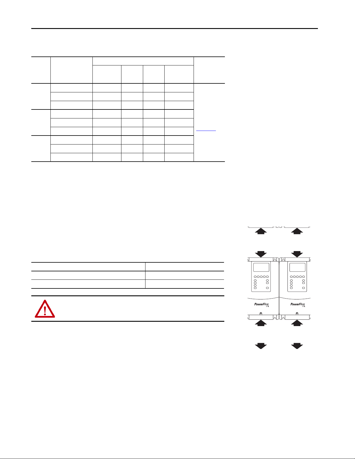
Before proceeding, be sure that all power to the drive has been removed.
ATT EN TI ON : Only qualified personnel familiar with adjustable frequency AC drives and associated machinery can perform maintenance/repair of the system.
Failure to comply can result in personal injury and/or equipment damage.
ATT EN TI ON : To avoid an electric shock hazard, verify that the voltage on the bus capacitors has discharged before performing any work on the drive. Measure
the DC bus voltage at the +DC and –DC terminals of the Power Terminal Block (refer to Frame A, B, C, D Power Terminal Block, and DC Bus Te st Points
for location). The voltage must be zero.
ATT EN TI ON : The following information is merely a guide for proper installation. Rockwell Automation cannot assume responsibility for the compliance or the
noncompliance to any code, national, local or otherwise for the proper installation of this drive or associated equipment. A hazard of personal injury and/or
equipment damage exists if codes are ignored during installation.
on page 19
26 Rockwell Automation Publication 20A-IN009F-EN-P - April 2018
Page 27

PowerFlex 70 Adjustable Frequency AC Drive
DC+
DC–
R/L1
S/L2
T/L3
MOV and AC EMI Capacitor Phase to Ground
Common Mode Capacitor to Ground
Jumper Wire
Jumper Wire
Volta ge Cat. No.
240 20AB…
480 20AD…
600 20AE…
IMPORTANT To guard against unstable operation and/or damage, you must configure the drive as shown in Recommended Power Jumper Configurations
The PowerFlex 70 drive contains protective MOVs and common mode capacitors that are referenced to ground (see below).
IMPORTANT The common mode capacitor to ground is not installed on A or B frames as standard. It is available for the B frame if the EMF
filter option is installed. The common mode capacitor to ground comes standard on C, D, and E frames.
IMPORTANT All PowerFlex 70 240V, 480V, and 600V AC input drives are shipped with the DC bus common mode capacitors that are
referenced to ground. Specific drive catalog numbers are listed.
on page 27.
See Wiring and Grounding Guidelines for PWM AC Drives, publication DRIVES-IN001 for information on ungrounded systems.
Recommended Power Jumper Configurations
Power Sourc e Type
Unknown Connected Disconnected See solid and non-solid ground points below
Solid ground
• AC fed, solidly grounded
• DC fed from passive rectifier that has an AC source and solid
Non-solid ground
• AC fed ungrounded
• Impedance grounded
• High resistive ground
• B phase ground
• Regenerative unit such as common DC bus supply and brake
• DC fed from an active converter
(1) It is highly recommended to accurately de termine the power source type and then configure appropriately.
(2) When MOVs are disconnected, the power system must have its own transient protection to help ensure known and controlled voltages.
To connect or disconnect these devices, refer to pages 28 through 30.
In addition to the configurations described in this section, install an isolation transformer on an ungrounded distribution system where the line-toground voltages on any phase can exceed 125% of the nominal line-to-line voltage. See Wiring and Grounding Guidelines for PWM AC Drives,
publication DRIVES-IN001 for more information on impedance grounded and ungrounded systems.
Benefits of Correct Configuration on Power Source
Type
•UL compliance
• Reduced electrical noise
• Most stable operation
•EMC compliance
• Reduced voltage stress on components and motor
bearings
Helps to avoid severe equipment damage when a ground
fault occurs.
ground
(1)
MOV/ Input Filter Caps
Connected Connected
Disconnected Disconnected
(2)
DC Bus Common Mode Caps
IMPORTANT Common mode capacitors are required to conform with the EMC Directive. Removing the common mode capacitors causes the drive to be non-compliant
with the EMC Directive.
Rockwell Automation Publication 20A-IN009F-EN-P - April 2018 27
Page 28
PowerFlex 70 Adjustable Frequency AC Drive
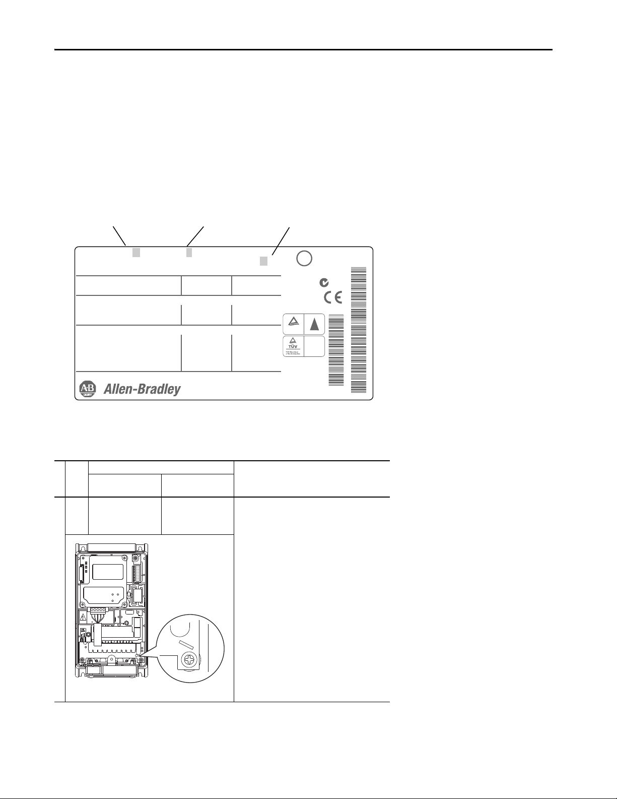
Cat No. 20A D xxx x x xxxxxxx
Mfg. in U.S.A. (FAC1J)
UL TYPE 1/IP20 and 50C (122F) Ambient Limit
Mfd. in 2008 on Jan 19
Serial No. xxxxxxx
Series: A
Frame: A
Original Firmware No. x.xxx
LISTED INDUCTRIAL
CONTROL EQUIPMRNT
966X
U
c
US
L
®
Normal Duty Power
Heavy Duty Power
AC Voltage Range
Amps
Input: 3 Phase, 47-63Hz
Output: 3 Phase, 0-400 Hz
AC Voltage Range
Base Frequency (default)
Continuous Amps
3 Sec / 60 Sec Ovld Amps
xxx kW
xxx kW
342-440
xxx
0-400
50 Hz
xxx
xxx
xxx HP
xxx HP
432-528
xxx
400V Class
See Manual for additional ratings
480V Class
0-460
60 Hz
x
xxx / xx
N223
Serial Number
catalog number/series
TUV
Rheinland
Product Safety
..
Production inspected
W
E
C
EN 50178
Volt age Cod e Internal EMC Option Frame
JP3
JP2
Jumper Installation, Removal, and Storage
PowerFlex 70 drives use plug-in style jumpers. Most drives have a jumper storage area inside the front cover. Store any extra jumpers, or jumpers that
have been removed, in this storage area.
In some cases, a protective cover is installed over the jumper pins that extend from the board. If there is a protective cover, remove the cover, install
(or remove) the jumper, and replace the cover.
Drive Identification
See the example of the drive nameplate and locate the voltage code, frame, and internal EMC option (frame B drives). Use this information to locate
the proper procedure in the following tables.
Jumper Settings and Locations
Factory Default Jumper Settings
MOV /Input Filter Caps
Frame
Volta ge
Code
A B
C
JP2/JP3
D
Installed
E
28 Rockwell Automation Publication 20A-IN009F-EN-P - April 2018
DC Bus Common Mode
Caps
Not applicable
MOV
Power S ource Type
Solid ground
Verify that the jumper at “JP2/JP3” is installed.
Non-solid ground
Remove the jumper at “JP2/JP3.”
Page 29

B B
or
JP6 JP5
JP3
JP2
MOV
CM Cap
L1RL2SL3TBR1
+DC
L1RL2SL3
T
Input Filter
Option
JP3
JP2
JP5
JP6
MOV
CM Cap
L1RL2SL3TBR1
+DC
L1RL2SL3
T
Input Filter
Option
JP3 JP2
JP3A
JP3B
MOV / Filter Cap
CM Cap
Factory Default Jumper Settings
MOV /Input Filter Caps
Frame
Volta ge
Code
JP2/JP3
D
Installed
E
JP2/JP3
C
Installed
DC Bus Common Mode
Caps
JP5/JP6
Installed
JP5/JP6
Installed
Power S ource Type
Important: The internal EMC filter (input filter) is a
factory-installed option on frame B drives. If the option is
installed, the drive cannot be used on a non-solid ground
power source.
To verify: an extra “R, S, T” terminal block is present if the
option is installed (as shown). Additionally, the 13th character
of the nameplate catalog number is “A” (see page 28
).
Solid ground
Verify that the jumpers at both locations are installed (JP2/JP3
and JP5/JP6).
Non-solid ground
Remove the jumpers at “JP2/JP3” and “JP5/JP6.” In addition,
verify that the input filter option is not installed.
PowerFlex 70 Adjustable Frequency AC Drive
C B
D
E
C
JP2/JP3
Installed
JP2/JP3
Installed
JP3A/JP3B
Installed
JP3A/JP3B
Installed
Solid ground
Verify that the jumpers at both locations (JP2/JP3 and JP3A/
JP3B) are installed.
Non-solid ground
Remove the jumpers at “JP2/JP3” and “JP3A/JP3B”.
Rockwell Automation Publication 20A-IN009F-EN-P - April 2018 29
Page 30

PowerFlex 70 Adjustable Frequency AC Drive
JP3
JP2
JP3A
JP3B
MOV / Filter Cap
CM Cap
SHLD
JP1 JP2
JP4
JP3
MOV /
Filter Cap
CM Cap
Factory Default Jumper Settings
DC Bus Common Mode
Caps
JP3A/JP3B
Installed
JP3A/JP3B
Installed
D B
Frame
Volta ge
Code
D
E
C
MOV /Input Filter Caps
JP2/JP3
Installed
JP2/JP3
Installed
Power S ource Type
Solid ground
Verify that the jumpers at both locations (JP2/JP3 and JP3A/
JP3B) are installed.
Non-solid ground
Remove the jumpers at “JP2/JP3” and “JP3A/JP3B”.
E B
JP1/JP2
D
Installed
E
JP1/JP2
C
Installed
JP3/JP4
Installed
JP3/JP4
Installed
Solid ground
Verify that the jumpers at both locations (JP1/JP2 and JP3/JP4)
are installed.
Non-solid ground
Remove the jumpers at “JP1/JP2” and “JP3/JP4.”
30 Rockwell Automation Publication 20A-IN009F-EN-P - April 2018
Page 31

PowerFlex 70 Adjustable Frequency AC Drive
Step 4: I/O Wiring
Important points to remember about I/O wiring:
• Use copper wire. Wire gauge requirements and recommendations are based on 75 °C (167 °F). Do not reduce wire gauge when you are using
higher temperature wire.
• Wire with an insulation rating of 600V or greater.
• Control and signal wires must be separated from power wires by at least 0.3 m (1 ft).
IMPORTANT I/O terminals that are labeled “(–)” Digital In Common or “Common” are not connected to earth ground and are designed to greatly reduce common mode
interference. Grounding these terminals can cause signal noise.
ATT EN TI ON : Hazard of personal injury or equipment damage exists when usin g bipolar input sources. Noise and drift in sensitive input circuits can cause
unpredictable changes in motor speed and direction. Use speed command parameters to help reduce input source sensitivity.
Typical I/O Terminal Block Location (B Frame Shown)
I/O Terminal Block Specifications
(1)
No. Name Description
➊
I/O terminal block
(1) Maximum / Minimum that the terminal block can accept - these are not recommendations.
Signal and control
connections
Wire Size R ange
Max Min Max Recommended
2
1.5 mm
(16 AWG)
0.05 mm
(30 AWG)
2
Wire Routing Recommendations
No. Description
Suggested entry for communication wiring.
➋
Suggested entry for I/O and control wiring.
➌
Rockwell Automation Publication 20A-IN009F-EN-P - April 2018 31
Torq ue
0.55 N•m
(4.9 lb•in)
0.5 N•m
(4.4 lb•in)
Page 32

PowerFlex 70 Adjustable Frequency AC Drive
I/O Terminal Positions
I/O Terminal Designations – Enhanced Control
No. Signal Factor y Default Description
1 Digita l In 1
2 Digita l In 2 Start
3 Dig ital In 3 Auto/Man
4 Dig ital In 4 Speed Sel 1
5 Dig ital In 5 Speed Sel 2
Stop – CF
(CF = Cl ear Fault)
11.2 mA at 24V DC
19.2V minimum on state
3.2V maximum off state
Important: Use only 24V DC, not suitable for 115V AC circuitry.
Inputs can be wired as sink or source.
Important: Digital inputs are not designed to work with a pulsed source.
6 Dig ital In 6 Speed Sel 3
7 24V Common –
Drive supplied power for Digital In1…6 inputs.
Not intended for use on circuits outside of the drive.
9+24V DC –
150 mA maximum load.
10 +10V DC Pot Reference – 2 k ohm minimum load. –
11 Digital O ut 1 – N.O.
(1)
12 Digital O ut 1 Common
13 Digital O ut 1 – N.C.
(1)
14 Analog In 1 (– Volts)
15 Analog In 1 (+ Volts)
16 Analog In 1 (– Current)
17 Analog In 1 (+ Current)
18 Analog In 2 (– Volts)
19 Analog In 2 (+ Volts)
20 Analog In 2 (– Current)
21 Analog In 2 (+ Current)
10V Pot Common
22
Analog Out (– Volts)
Analog Out (– Current)
Analog Out (+ Volts)
23
Analog Out (+ Current)
24 Digital O ut 2 – N.O.
(1)
NOT Fault Max resistive load
250V AC / 30V DC
50VA / 60 W
Faul t
(2)
Min DC load
10 μA, 10 mV DC
Non-isolated, 0…+10V, 10 bit, 100k ohm input impedance.
TB Man Ref
Voltage – Reads value at 14 & 15
(2)
Non-isolated, 0…20 mA, 10 bit, 100 ohm input impedance.
Isolated, bipolar, differential, 0…+10V unipolar (10 bit) or ±10V bipolar (10 bit and
sign), 100k ohm input impedance.
Speed Ref A
Voltage – Reads value at 18 & 19
(2)
Output Freq
Isolated, 0…20 mA, 10 bit, and sign, 100 ohm input impedance.
0…+10V, 10 bit, 10k ohm (2k ohm minimum) load.
0…20 mA, 10 bit, 400 ohm maximum load.
Referenced to chassis ground.
Common if internal 10V supply (terminal 10) is used.
Run
Max inductive load
250V AC / 30V DC
25VA / 30 W
(4)
(3)
(3)
(4)
See description at No.s 11…13. 380…38725 Digital O ut 2 Common
26 Digital O ut 2 – N.C.
(1) Contacts shown in unpowered state. Any relay that is programmed as fault or alarm energizes (pick up) when power is applied to drive and de-energizes (drop out) when fault or alarm exists. Relays selected for othe r functions
energize when the condition exists, and de-energize when the condition is removed.
(2) These inputs/outputs are dependent on a number of parameters. See the Related Parameters column in I/O Terminal Designations – Enhanced Control.
(3) Differential isolation - external sou rce must be less than 10V regarding PE.
(4) Differential isolation - external source must b e maintained at less than 160V regarding PE. Input provides high common mode immu nity.
(1)
NOT Run
Related
Paramete rs
361…366
–8 Digita l In Common –
380…387
320…327
340…344
32 Rockwell Automation Publication 20A-IN009F-EN-P - April 2018
Page 33

I/O Wiring Examples
18
19
22
10
18
19
Common
+
2
7
8
9
Stop-Run
1
2
7
8
9
Run Fwd
Run Rev
1
2
7
8
9
Stop
Start
+24V Common
1
2
8
Stop
Start
11
12
13
24
25
26
Power
Source
or
This section shows examples of typical I/O wiring.
Input/Output Connection Example Required Parameter Settings
Selec t speed refere nce source:
Potentiometer unipolar speed
reference
10k Ohm pot. recommended
(2k Ohm minimum)
Analog input unipolar speed
reference
0…+10V Input
Two-w ire control
non-reversing
(1)
Internal supply
Param. 090 = 2 “Analog In 2”
Adjust Scaling:
Param. 091, 092, 322, 323
Check results:
Param . 017
Default speed reference source:
Param. 090 = 2 “Analog In 2”
Adjust Scaling:
Param. 091, 092, 325, 326
Check results:
Param . 017
Disable Digital Input 1:
Param. 361 = 0 “Not Used”
Set Digital Input 2:
Param. 362 = 7 “Run”
PowerFlex 70 Adjustable Frequency AC Drive
Two-w ire control reversing
Three-wire control
Three-wire control
(1)
(1)
(1)
Digital output
Form C relays en ergized in normal
state
Internal supply
Internal supply
External supply
Set Digital Input 1:
Param. 361 = 9 “Run Reverse”
Set Digital Input 2:
Param. 362 = 8 “Run Forward”
Use factory default parameter settings.
Digital Input 1:
Param. 361 = 4 “Stop – CF”
Digital Input 2:
Param. 362 = 5 “Start”
Use factory default parameter settings.
Digital Input 1:
Param. 361 = 4 “Stop – CF”
Digital Input 2:
Param. 362 = 5 “Start”
Select source:
Use factory default parameter settings.
Digital Out1 Sel:
Param. 380 = 1 “Fault”
Digital Out2 Sel:
Param. 384 = 4 “Run”
Rockwell Automation Publication 20A-IN009F-EN-P - April 2018 33
Page 34
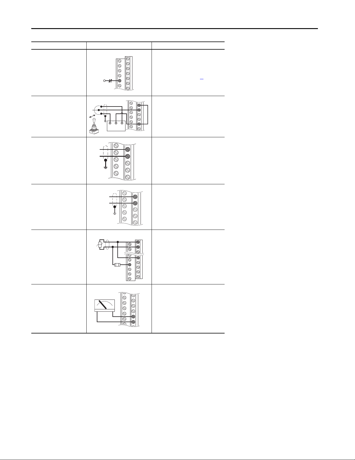
PowerFlex 70 Adjustable Frequency AC Drive
6
18
19
22
Com
Power Source
-10V +10V
18
19
–
+
+
14
15
22
10
3.32k
Ohm
1.8k
PTC
Ferrite
Bead
+–
Input/Output Connection Example Required Parameter Settings
Enable input
Shown in enabled state.
Important: Digi
designed to work with a pulsed
tal inputs are not
Param. 366 = 1 “Enable”
For dedicated hardware enable,
remove enable jumper (see page 35
source.
Set direction mode:
Param. 090 = 2 “Analog In 2”
Joystick bipolar speed reference
±10V input
Param. 190 = 1 “Bipolar”
Adjust scaling:
Param. 091, 092, 325, 326
Check results:
Param . 017
)
Analog input bipolar speed
reference
±10V input
Analog input unipolar speed
reference
0…20 mA input
Analog input,
positive temperature coefficient
PTC OT set > 5V
PTC OT cleared < 4V
PTC Short < 0.2V
Analog output unipolar
0…+10V output.
Can drive a 2k Ohm load (25 mA short
circuit limit)
0…20 mA output.
400 Ohm max load.
Common
Adjust scaling:
Param. 091, 092, 325, 326
Check results:
Param . 017
Configure input for current:
20
Param. 320, Bit #1 = 1 “Current”
21
Adjust scaling:
Param. 091, 092, 325, 326
Check results:
Param . 017
Set Fault Config 1:
Param. 238, Bit #7 = 1 “Enabled”
Set Alarm Config 1:
Param. 259, Bit #11 = 1 “Enabled”
Select source value:
Param . 342
Adjust scaling:
Param. 343, 344
22
23
(1) Dig ital inputs can be wired f or 2-wire or 3 -wire star t/stop contro l. Three-wire con trol requires s eparate Star t and Stop si gnals. Two-wire cont rol requires
one input signal configured Run-Hi /Stop-Lo.
34 Rockwell Automation Publication 20A-IN009F-EN-P - April 2018
Page 35

Hardware Enable Circuitry
1234
0.8…1.1 N•m
(7…10 lb•in)
20A-DG01
By default, you can program a digital input as an enable input. The status of this input is interpreted by drive
software. If the application requires the drive to be disabled without software interpretation, a hardware
enable configuration is used. To use the hardware enable configuration, remove the enable jumper (ENBL
JMP) and connect the enable input to Digital In 6 (see below).
1. Remove the drive cover.
2. Locate and remove the enable jumper on the main control board (see the diagram).
3. Connect the enable to Digital In 6 (see I/O Terminal Designations – Enhanced Control
).
32
on page
Safe Torque Off Board Option
The optional PowerFlex Safe Torque Off board, when used with suitable safety components, provides
protection according to EN ISO 13849-1 and EN 62061 for Safe Torque Off and protection against restart.
The PowerFlex safe torque off option is just one safety control system. All components in the system must be
chosen and applied correctly, to achieve the desired level of operator safeguarding.
IMPORTANT The drive enable digital input is a solid-state circu it. The safety outputs on the safety module must not be
configured for pulsed/safety pulse test.
PowerFlex 70 Adjustable Frequency AC Drive
IMPORTANT The drive ships with the hardware enable jumper (ENBL JMP) installed. You must remove the jumper if you
are using the DriveGuard Safe Torque Off option. If you do not remove the jumper, the drive faults when a
start command is issued.
Terminal Description
No. Signal Description
1 Monitor - N.C. Normally closed contacts for monitoring relay status.
2Common - N.C.
3+24V DC
4 24V Common
For detailed information on installing and wiring a safety relay system, refer to the DriveGuard Safe Torque Off Option (Series B) for PowerFlex
40P and PowerFlex 70 AC Drives User Manual, publication PFLEX-UM003
IMPORTANT If the Safe Torque Off board is removed from the drive, pins 3 and 4 of the Safe
Torque Off connector must be jumpered for the drive to run. If the Safe Torque Off
board or the jumper is not installed, and the drive is commanded to run, an F111
Enable Hardware fault occ urs.
Maximum Resistive load: 250V AC / 30V DC / 50VA / 60 W
Maximum Inductive load: 250V AC / 30V DC / 25VA / 30 W
Connections for user-supplied power to energize coil.
.
Rockwell Automation Publication 20A-IN009F-EN-P - April 2018 35
Page 36

PowerFlex 70 Adjustable Frequency AC Drive
6
1
= 12V
= 5V
= 12V
= 5V
20A-ENC-1
0.8…1.1 N•m
(7…10 lb•in)
Receive Voltage
Send Voltage
Common
(250 mA)
to SHLD
Common
Power
Supply
to
SHLD
Common
(250 mA)
to SHLD
to SHLD
A NOT
B
A
B NOT
Encoder Interface Option
The optional PowerFlex encoder interface can source 5 volt or 12 volt power and accept 5 volt or 12 volt single-ended differential inputs. The
factory default setting is 12 volts.
Terminal Description
No. Signal Description
1 5 V or 12V power
2Power return
3Encoder B (NOT)
4Encoder B
5Encoder A (NOT)
6Encoder A
Internal power source 250 mA (isolated).
Single channel or quadrature B input.
Single channel or quadrature A input.
Sample Encoder Wiring
I/O Connection Example I/O Connection Example
+12V DC
Encoder power –
internal drive power
Internal (drive) 12V DC,
250 mA
Encoder signal –
single-ended, dual
channel
1
2
3
4
5
6
+12V DC
1
2
3
4
5
6
Encoder power –
external power
source
Encoder signal –
differential,
dual channel
+
External
1
2
3
4
5
6
Encoder Specifications
Topi c De scr ipt ion
Type Incremental, dual-channel
Supply 5V/12V Configurable ±5%
Quadrature 90° ±27°
Duty Cycle 50% +10%
Encoders must be line driver type, quadrature (dual channel), or pulse (single channel), single-ended or
Requirements
differential and capable of supplying a minimum of 10 mA per channel. The encoder interface board accepts
5V or 12V DC square-wave with a minimum high state voltage of 3.5V DC (5V mode) and 7.0V DC (12V
mode). Maximum low state voltage is 1V DC (for both 5V and 12V modes). Maximum input frequency is 250
kHz.
36 Rockwell Automation Publication 20A-IN009F-EN-P - April 2018
Page 37
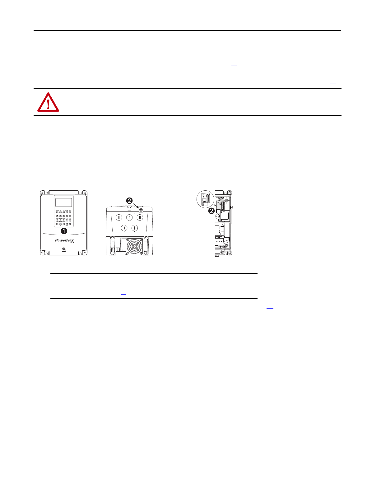
PowerFlex 70 Adjustable Frequency AC Drive
CTRL BD
GND
Optional Service
Connection Board (SKM9-SCB1) provides
temporary DPI
connection with drive
cover removed.
Step 5: Start-up Checklist
• This checklist supports the basic start-up menu option. See Start-up Routines on page 42 for information on other start-up routines.
• A HIM is required to run the basic start-up routine.
• The basic start-up routine can modify parameter values for analog and digital I/O. See Common I/O Programming Changes on page 44
ATT EN TI ON : Power must be applied to the drive to perform the following start-up procedure. Some of the voltages present are at incoming line potential. To
avoid electric shock hazard or damage to equipment, only qualified service personnel can perform the following procedure. Thoroughly read and understand the
procedure before beginning.
Prepare For Drive Startup
1. Verify the input supply voltage.
2. Check the output wiring.
3. Check the control wiring.
4. Connect a HIM to DPI Port 1 or 2.
DPI Ports 1 and 2
.
5. Apply AC power and control voltages to the drive.
IMPORTANT If any of the six digital inputs are configured to Stop – CF (CF = Clear Fault) or Enable, verify that
signals are present or the drive cannot start. See Troubleshooting – Abbreviated Fault and Alarm
Listing on page 45
for a list of potential digital input conflicts.
If the STS status indicator is not updating green, see Drive Status Indicators on page 44.
6. When prompted, select a display language.
The PowerFlex 70 start-up screen displays.
7. Press the enter key to display the start-up menu.
8. Use the arrow keys to highlight 2. Basic.
9. Press the enter key.
Use the enter key to follow the menu and step you through the start-up routine.
The basic start-up routine asks simple questions and prompts you to input required information. See also Common I/O Programming Changes on
.
page 44
Rockwell Automation Publication 20A-IN009F-EN-P - April 2018 37
Page 38

PowerFlex 70 Adjustable Frequency AC Drive
Information About Start-up Motor Tests
Control schemes vary based on the Start/Jog Source that is selected in Step 3. Motor Tests.
Start/Jog Source Control Source Description
Digital inputs Digital In 1 = Stop / Digital In 2 = Start / Digital In 3 = Jog
Local HI M – Port 1
Remote HIM
During motor tests and tuning procedures, the drive can modify certain parameter values for proper start-up operation. These values are reset to
their original values when startup is complete. The affected parameters are listed here:
•053
•080
•276
•278
•361…366
IMPORTANT If power is removed from the drive during the tests without aborting the autotune procedure, these
HIM connected to DPI Port 1 controls Stop / Start / Jog
Digital In 1…6 are temporarily disabled during motor tests.
HIM connected to DPI Port 2 controls Stop / Start / Jog
Digital In 1…6 are temporarily disabled during motor tests.
parameters may not reset to their original value. If this situation occurs, reset the drive to factory defaults
(see page 44) and repeat the start-up procedure.
38 Rockwell Automation Publication 20A-IN009F-EN-P - April 2018
Page 39
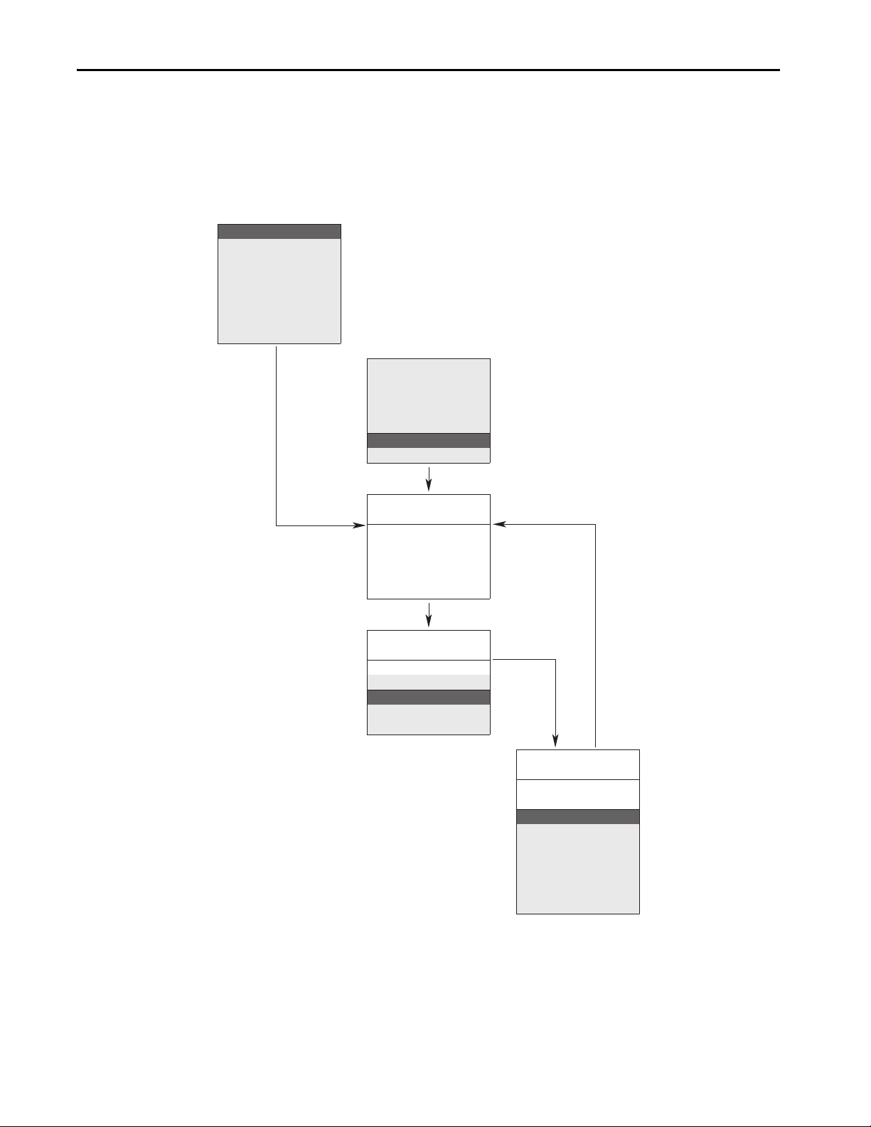
English?
Fran çais?
¿Español?
Italiano?
Deutsch?
Português?
Nederlands?
Not Selected
Main Menu:
Diagnostics
Param eter
Device Select
Memory Storage
Start-Up
Preferences
PowerFlex 70
Start-Up
Startup consists
of several steps
to congure a
drive for basic
applications.
PowerFlex 70
Start-Up
Make a selection
1. SMART
2. Basic
3. Detailed
4. More info
PowerFlex 70
Start-Up
Complete these
steps in order:
1. Motor Control
2. Motr Data/Ramp
3. Motor Tests
4. Speed Limits
5. Speed/Trq Cntl
6. Start/Stop/I/O
7. Done/Exit
PowerFlex 70 Adjustable Frequency AC Drive
Appendix A: Startup and Troubleshooting
This section includes information for starting and troubleshooting the drive.
First Power-up Menu Structure
Rockwell Automation Publication 20A-IN009F-EN-P - April 2018 39
Page 40

PowerFlex 70 Adjustable Frequency AC Drive
F-> Power Loss Auto
0.0
Hz
Main Menu:
Diagnostics
Para me ter
Device Select
Esc
HIM
Esc
7 8 9
4 5 6
1 2 3
.
0 +/-
Sel
Jog
Alt
Exp
Param #
S.M.A.R.T.
View
Lang
Auto / Man
Remove
Sel
ALT
Jog
Human Interface Module (HIM) Overview
This section provides information for operating the HIM.
LCD Display Elements
Display Description
Direction Drive Status Alarm Auto/Man Information
Commanded or Output Frequency
Programming / Monitoring / Troubleshooting
HIM Key Functions
Key Description
Exit a menu, cancel a change to a parameter value, or
acknowledge a fault/alarm.
Select a digit, select a bit, or enter edit mode in a parameter
screen.
Scroll through options, increase a value, or toggle a bit.
Scroll through options, decrease a value, or toggle a bit.
Enter a menu, enter edit mode in a parameter screen, or save a
change to a parameter value.
Access the function that is associated with a programming or
numeric key. Provides access to the Large Format Display. See
the drive user manual for more information.
Start the drive.
Stop the drive or clear a fault.
Jog the drive.
Change direction.
Increase speed.
These keys are active when the HIM is granted Manual Control or Param. 090 [Speed Ref A
Sel] / 093 [Speed Ref B Sel] is set to:
Option 18 “DPI Port 1” for a HIM installed in the drive cover
or
Option 19 “DPI Port 2” for a HIM connected by cable for handheld or remote installation
Decrease speed.
option
40 Rockwell Automation Publication 20A-IN009F-EN-P - April 2018
Page 41
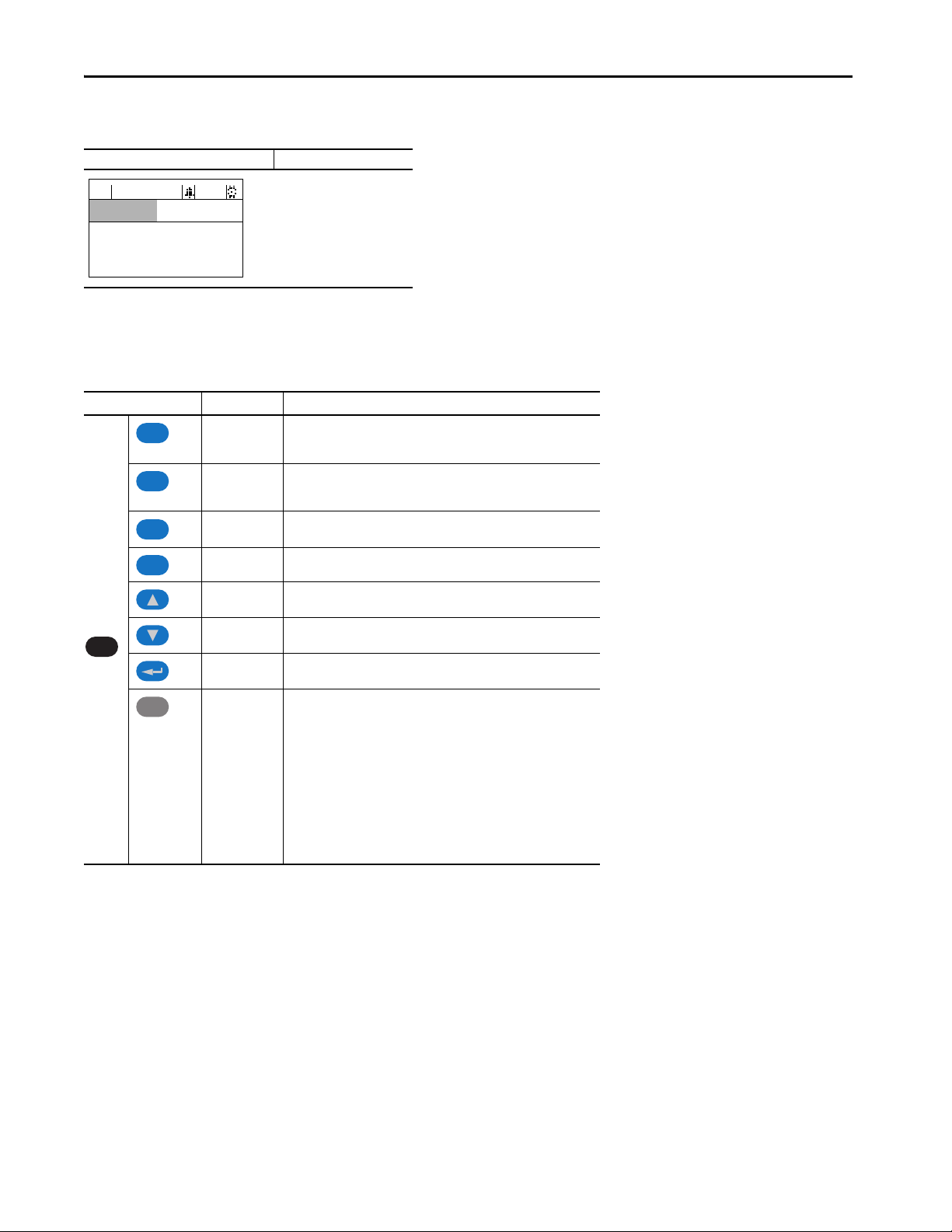
PowerFlex 70 Adjustable Frequency AC Drive
F-> Power Loss Auto
0.0
Hz
Main Menu:
Diagnostics
Para me ter
Device Select
ALT
Esc
Esc
Sel
Sel
+/–
HIM Main Menu
Main Menu Screen Menu Selections
Main Menu:
Diagnostics
Para meter
Device Select
Memory Storage
Start-Up
Preferences
ALT Functions
To use an ALT function, start at the Main Menu and press the ALT key, release it, then press the programming key that is associated with one of the
following functions that are listed in the table.
ALT Key then Func tion Function Description
S.M.A.R.T.
Log In /Out
View
Displays the S.M.A.R.T. screen. This function enables the drive parameter values
to be quickly programmed by directly accessing the most frequently used drive
functions. See the user manual for more information.
Log in to change parameter settings.
Log out to preserve parameter settings.
Change a password.
Enables the selection of how parameters are viewed or detailed information
about a parameter or component.
Device Select a connec ted adapter for editi ng.
Lang
Auto / Man
Remove
Param # Enables entry of a parameter number for viewing/editing.
Displays the language selection screen. The LCD HIM on an architecture class
drive enables you to change the display language any time.
Switches between Auto and Manual Modes. If the HIM requests Manual Mode,
the Speed Reference source is transferred to the HIM.
Enables HIM removal without causing a fault if the HIM is not the last controlling
device and does not have manual control of the drive.
Rockwell Automation Publication 20A-IN009F-EN-P - April 2018 41
Page 42

PowerFlex 70 Adjustable Frequency AC Drive
(1) (2)
Main Menu:
Start-Up
Motor Control
Select
Motor Data and
Ramp Times
Motor Tests
Speed Limits
Speed/Torque
Control
Start/Stop/I/O
Done /
Exit
Congures
Motor Control
Method
Enter Motor NP
Data, Stop Mode,
Accel/Decel
Ramp Times
Optimize Torque
and
Verify Direction
Set Min/Max
Speed and
Direction
Control
Congure
Source, Value
and Scale for
Speed References
Congure
Control Method
(2 Wire/3 Wire), I/O,
Digital Inputs/
Outputs and
Analog Outputs
Application
Congure
for Specic
Application
Start-up Routines
The PowerFlex 70 is designed so that startup is simple and efficient. If you have an LCD HIM, two start-up methods are provided. Select the desired
start-up routine that is needed for the application:
• S.M.A.R .T. Start
This routine lets you quickly configure the drive by programming values for the most commonly used functions (see Running S.M.A.R.T. Start on
).
page 43
• Assisted Startup
This routine prompts you for information to start up a drive for most applications, such as line and motor data, commonly adjusted parameters, and
I/O. With enhanced control, two levels of assisted startup are available: basic and detailed (see Running an Assisted Startup on page 43
IMPORTANT Power must be applied to the drive when viewing or changing parameters. Previous
programming can affect the drive status when power is applied.
Enhanced Control Start-up Menu
).
(1)
During motor tests and tuning procedures, the drive can mod ify certain parameter values for proper start-up operation. These values are then reset to their original values when startup is complete. The affected parameters are:
053, 080, 276, 278, and 361…366. If power is removed from the drive during the tests without aborting the autotune procedure, these parameters may not reset to their original value. If thi s situation occurs, reset the drive to
factory defaults (see page 44
(2)
Only in Detailed Startup mode.
) and repeat the start-up procedure.
42 Rockwell Automation Publication 20A-IN009F-EN-P - April 2018
Page 43

PowerFlex 70 Adjustable Frequency AC Drive
ALT
Esc
Esc
F-> Stopped Auto
0.0
Hz
Main Menu:
Diagnostics
Para me ter
SMART List:
Digital In2 Sel
Stop Mode A
Minimum Speed
F-> Stopped Auto
0.0
Hz
Main Menu:
Memor y Storag e
Start Up
Preferences
Running S.M.A.R.T. Start
During a startup, most applications require changes to a few parameters. The LCD HIM on a PowerFlex 70 drive offers S.M.A.R.T. start, and
displays the most commonly changed parameters. With these parameters you can set the following functions:
• S – Start Mode and Stop Mode
• M – Minimum and Maximum Speed
• A – Accel Time 1 and Decel Time 1
• R – Reference Source
•T – Thermal Motor Overload
To run a S.M.A.R.T. start routine, follow the steps in this table:
Step Keys Example LCD Displays
1. Press ALT and then Esc (S.M.A.R.T). The S.M.A.R.T. start screen
appears.
2. View and change parameter values as desired. For HIM
information, see Appendix B.
3. Press Esc to exit the S.M.A.R.T. start.
Running an Assisted Startup
IMPORTANT This start-up routine requires an LCD HIM.
The assisted start-up routine prompts you to input required information. Access assisted startup by selecting Start Up from the Main Menu.
To perform an assisted startup, follow the steps in this table:
Step Keys Example LCD Displays
1. In the Main Menu, press the up arrow or down arrow to scroll to
Start Up.
2. Press Enter.
IMPORTANT You must select Done/Exit after you complete the start-up routine for the start-up/autotune
data to be saved.
Rockwell Automation Publication 20A-IN009F-EN-P - April 2018 43
Page 44
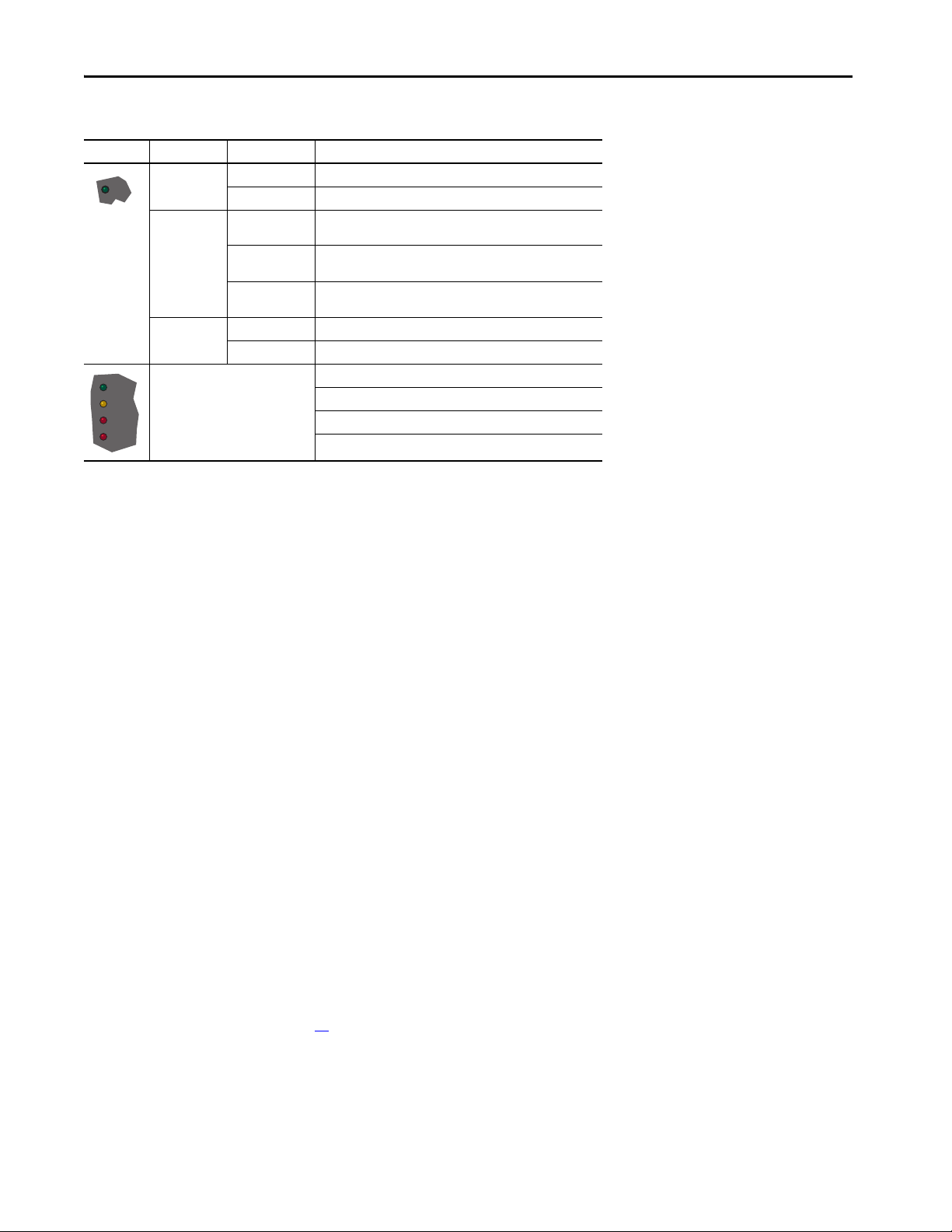
PowerFlex 70 Adjustable Frequency AC Drive
STS
PORT
MOD
NET A
NET B
Drive Status Indicators
Name Color State Description
Green
Yel l ow
Red
See the communication adapter user
manual.
Updating The drive is ready but is not running, and no faults are present.
Steady The drive is running and no faults are present.
Updating,
drive stopped
Updating,
drive running
Steady,
drive running
Updating A fault has occurred.
Steady A non-resettable fault has occurred.
An inhibit condition exists, the drive cannot be started. Check parameter
214 [Start Inhibits].
An intermittent type 1 alarm condition exists.
Check parameter 211 [Drive Alarm 1].
A continuous type 1 alarm condition exists.
Check parameter 211 [Drive Alarm 1].
Status of DPI port internal communications (if present).
Status of communications module (when installed).
Status of network (if connected).
Status of secondary network (if connected).
Common I/O Programming Changes
Your application needs can require changing parameters from their factory default settings.
Speed Reference A
Change Speed Reference A from Analog In 2 to Analog In 1 to connect an external potentiometer.
1. Set Parameter 090 [Speed Ref A Sel] to option 1, Analog In 1.
Sets the speed reference input to I/O terminals 14 and 15 for voltage, and I/O terminals 16 and 17 for current.
2. Set Parameter 096 [TB Man Ref Sel] to option 9, MOP Level.
Minimizes a potential conflict alarm condition. Analog In 2 is not a valid Speed Reference source if selected for any of the following
parameters:
•117 [Trim In Select]
• 126 [PI Reference Sel]
• 128 [PI Feedback Sel]
• 147 [Current Lmt Sel]
3. Set Parameter 091 [Speed Ref A Hi] to the upper value of the desired speed reference range in Hz.
4. Set Parameter 092 [Speed Ref A Lo] to the lower value of the desired speed reference range in Hz.
Speed Reference A is now configured for an external potentiometer.
Control Scheme
Change from 3-wire Start/Stop to 2-wire Run/Not Run at Digital In 1 and Digital In 2.
1. Set Parameter 361 [Digital In1 Sel] to option 7 Run, or 9 Run Reverse.
2. Set Parameter 362 [Digital In2 Sel] to another option such as 8 Run Forward, or 10 Jog.
See I/O wiring examples beginning on page 31
.
Restoring Factory Defaults
From the HIM Main Menu, select Memory Storage/Reset To Defaults.
44 Rockwell Automation Publication 20A-IN009F-EN-P - April 2018
Page 45

Troubleshooting – Abbreviated Fault and Alarm Listing
For a complete listing of faults and alarms, refer to the PowerFlex 70 User Manual, publication 20A-UM001.
Abbreviated Fault Table
PowerFlex 70 Adjustable Frequency AC Drive
Fault
Auxiliary Input 2
Decel Inhibit 24
FluxAmpsRef Rang 78
HW OverCurrent 12
IR Volts Range 77
Motor Overload 7
OverSpeed Limit 25
OverVoltage 5
SW OverCurrent 36
(1) See the PowerFlex 70 User Manual, publicati on 20A-UM001, for a description of fault ty pes.
(1)
No.
Description Action
Type
Auxiliary input interlock is open. Check remote wiring.
➊
The drive is not following a commanded
deceleration because it is attempting to limit
➌
bus voltage.
The value for flux amps determined by the
Autotune procedure exceeds the programmed
[Motor NP FLA].
The drive output current has exceeded the
➊
hardware current limit.
“Calculate” is the autotune default and the
value that is determined by the autotune
procedure for IR Drop Volts is not in the range
of acceptable values.
➊
Internal electronic overload trip.
Enable/Disable with [Fault Config 1].
➌
Functions such as Slip Compensation or Bus
Regulation have attempted to add an output
➊
frequency adjustment greater than the value
programmed in [Overspeed Limit].
DC bus voltage exceeded maximum value.
➊
Drive output current has exceeded the 1 ms
current rating. This rating is greater than the 3
second current rating and less than the
➊
hardware o vercurrent fau lt level. It i s typicall y
200…250% of the drive continuous rating.
Verify that input voltage is within drive
specified limits.
Verify that system ground impedance
follows proper grounding techniques.
Disable bus regulation and/or add
dynamic brake resistor and/or extend
deceleration time.
Reprogram [Motor NP FLA] with the
correct motor nameplate value.
Repeat Autotune.
Check programming. Check for excess
load, improper DC boost setting, DC brake
volts set too high, or other causes of
excess current.
Reenter motor nameplate data.
An excessive motor load exists. Reduce
load so drive output current does not
exceed the current set by [Motor NP FLA].
Remove excessive load or overhauling
conditions or increase [Oversp eed Limit] .
Monitor the AC line for high line voltage
or transient conditions. Motor
regeneration can also cause a bus
overvoltage. Extend the decel time or
install dynamic brake option.
Check for excess load, improper DC boost
setting. DC brake volts set too high.
Rockwell Automation Publication 20A-IN009F-EN-P - April 2018 45
Page 46

PowerFlex 70 Adjustable Frequency AC Drive
Acc2/Dec2 Accel 2 Decel 2 J og Jog Fwd Jog Rev Fwd/Rev
Acc2 / Dec2 X X
Accel 2 X
Decel 2 X
Jog X X
Jog Fwd X X
Jog Rev X X
Fwd / Rev X X
Start Stop–CF Run Run Fwd Run Rev Jog Jog Fwd Jog Rev
Fwd/
Rev
Start X X X X X
Stop–CF
Run X X X X X
Run Fwd X X X X
Run Rev X X X X
Jog X X
Jog Fwd X X
Jog Rev X X
Fwd / Rev X X
E C
Abbreviated Alarm Table
(1)
Alarm
No.
Dig In ConflictA 17 2
Description
Typ e
Digital input functions are in conflict. Combinations that are marked with an “X” cause an
alarm.
A digital Start input has been configured without a Stop input or other functions are in
conflict. Combinations that conflict are marked with an “X” and causes an alarm.
Dig In ConflictB 18 2
Multiple physical inputs have been configured to the same input function. Multiple
configurations are not allowed for the following input functions:
Dig In ConflictC 19 2
• Forward/Reverse, Run Reverse, Bus Regulation Mode B
• Speed Select 1, Jog Forward, Acc2 / Dec2
• Speed Select 2, Jog Reverse, Accel 2
• Speed Select 3, Run, Decel 2
• Run Forward, Stop Mode B
Occurs when:
“Auto/Manual” is selected (default) for [Digital In3 Sel], parameter 363
and
[TB Man Ref Sel], parameter 96 has been reprogrammed.
No other use for the selected analog input can be programmed.
TB Man Ref Cflct
30
Example: If [TB Man Ref Sel] is reprogrammed to “Analog In 2,” all factory default uses for
“Analog In 2” must be reprogrammed (such as parameters 90, 117, 128 and 179). See the
Auto/Manual Examples section of the PowerFlex 70 User Manual,
publication 20A-UM001
.
To c orr ec t:
Verify/reprogram the parameters that reference an analog input
or
Reprogram [Digital In3] to another function or “Unused.”
(1) See PowerFlex 70 User Manual, publication 20A-UM001, for a description of alarm types.
46 Rockwell Automation Publication 20A-IN009F-EN-P - April 2018
Page 47

Common Symptoms and Corrective Actions
Drive Does Not Start From Start or Run Inputs Wired to the Terminal Block
Cause Indication Corrective Action
Clear fault.
Drive is Faulted
Incorrect input wiring.
See page 31
for wiring examples.
• Two wire contro l requires Ru n, Run Forwa rd, Run
Reverse or Jog input.
• Three wire control requires Start and Stop inputs
• Jumper from terminal 7 to 8 is required.
Incorrect digital input programming.
• Mutually exclusive choices have been made (that
is, Jog and Jog Forward).
• 2-wire and 3-wire programming can be
conflicting.
• Exclusive functions (for example, direction control)
can have multiple inputs that are configured.
• Stop is factory default and is not wired.
Safe Torque Off Option Installed
• Hardware Enable Input “Digital In 6” not present.
Safe Torque Off Option inputs not present.
Updating red status
light
Updating green status
light
None
Updating yellow status
light and “DigIn
CflctB” indication on
LCD HIM.
[Drive Status 2] shows
type 2 alarms.
Updating yellow status
light and “Not Enable”
indication on LCD HIM.
Updating yellow status
light and “Safe Torque
Off” indication on LCD
HIM.
•Press Stop
•Cycle power
• Set [Fault Clear] to 1
• “Clear Faults” on the HIM Diagnostic menu
Wire inputs correctly and/or install jumper.
Program [Digital Inx Sel] for correct inputs.
Start or Run programming can be missing.
Program [Digital Inx Sel] to resolve conflicts.
Remove multiple selections for the same func tion.
Install stop button to apply a signal at stop
terminal.
Verify correct wiring to “Digital In 6.”
Check for presence of signal.
Wire inputs correctly on Safe Torque Off option
terminals 1...4.
See the DriveGuard Safe Torque Off Option User
Manual, publication
PFLEX-UM003
for more information
PowerFlex 70 Adjustable Frequency AC Drive
Drive Does Not Start From the HIM
Cause Indication Correc tive Action
Drive is programmed for 2-wire control. Human
interface module (HIM) Start button is disabled
for 2-w ire control.
None
If 2-wire control is required, no action is necessary.
If 3-wire control is required, program [Digital Inx Sel] for
correct inputs.
Drive Does Not Respond to Changes in Speed Command
Cause Indication Corrective Action
No value is coming from the source of the
command.
Incorre ct reference s ource has bee n
programmed.
Incorre ct reference s ource is bein g
selected via remote device or digital
inputs.
LCD HIM Sta tus
Line indicates
“At Speed” and
output is 0 Hz.
None
None
1. If the source is an analog input, check wiring and use a meter to
check for presence of signal.
2. Check [Commanded Freq] for correct source.
1. Check [Speed Ref Source] for the source of the speed reference.
2. Reprogram [Speed Ref A Sel] for correct source.
1. Check [Drive Status 1], bits 12 and 13 for unexpected source
selections.
2. Check [Dig In Status] to see if inputs are selecting an alternate
source.
3. Reprogram digital inputs to correct “Speed Sel x” option.
Rockwell Automation Publication 20A-IN009F-EN-P - April 2018 47
Page 48

PowerFlex 70 Adjustable Frequency AC Drive
Esc
Motor and/or Drive does Not Accelerate to Commanded Speed
Cause Indication Corrective Action
Acceleration time is excessive. None Reprogram [Accel Time x].
Excess load or short acceleration times
force the drive into current limit, slowing
or stopping acceleration.
Speed command source or value is not as
expected.
Programming is preventing the drive
output from exceeding limiting values.
None
None
None
Check [Drive Status 2], bit 10 to see if the drive is in Current Limit.
Remove excess load or reprogram [Accel Time x].
Check for the proper Speed Command by using Drive Does Not
Respond to Changes in Speed Command on page 47.
Check [Maximum Speed] and [Maximum Freq] to verify that the speed
is not limited by programming.
Motor Operation is Unstable
Cause Indication Corrective Action
Motor data was incorrectly entered or
Autotune was not performed.
None
1. Correctly enter motor nameplate data.
2. Perform “Static” or “Rotate” Autotune procedure.
Manually Clearing Faults
Step Keys
1. Press Esc to acknowledge the fault.
The fault information is removed so that you can use the human interface module (HIM).
2. Address the condition that caused the fault.
The cause must be corrected before the fault can be cleared.
3. After corrective action has been taken, clear the fault by one of these methods:
–Press Stop.
–Cycle drive power.
– S et parameter 240 [Fault Clear] to “1”.
– “Clear Faults” on the human interface module (HIM) Diagnostic menu.
48 Rockwell Automation Publication 20A-IN009F-EN-P - April 2018
Page 49

Notes:
PowerFlex 70 Adjustable Frequency AC Drive
Rockwell Automation Publication 20A-IN009F-EN-P - April 2018 49
Page 50

Rockwell Otomasyon Ticaret A.Ş., Kar Plaza İş Merkezi E Blok Kat:6 34752 İçerenköy, İstanbul, Tel: +90 (216) 5698400
Rockwell Automation maintains current product environmental information on its website at
*PN-608463*
PN-608463
Rockwell Automation Support
Use the following resources to access support information.
Documentation Feedback
Your comments will help us serve your documentation needs better. If you have any suggestions on how to improve this document, complete the
How Are We Doing? form at http://literature.rockwellautomation.com/idc/groups/literature/documents/du/ra-du002_-en-e.pdf
.
Technical Support Center
Knowledgebase Articles, How-to Videos, FAQs, Chat, User
Forums, and Product Notification Updates.
https://rockwellautomation.custhelp.com/
Local Technical Support Phone Numbers Locate the phone number for your country. http://w ww.rockwellautomation.com/global/support/get-support-now.page
Direct Dial Codes
Find the Direct Dial Code for your product. Use the code to
route your call directly to a technical support engineer.
http://www.rockwellautomation.com/global/support/direct-dial.page
Literature Library
Installation Instructions, Manuals, Brochures, and
Technical Data.
http://www.rockwellautomation.com/global/literature-library/overview.page
Product Compatibility and Download
Center (PCDC)
Get help determining how products interact, check
features and capabilities, and find associated firmware.
http://www.rockwellautomation.com/global/support/pcdc.page
http://www.rockwellautomation.com/rockwellautomation/about-us/sustainability-ethics/product-environmental-compliance.page
Allen-Bradley, Rockwell Automation, and Rockwell Software are trademarks of Rockwell Automation, Inc.
Trademarks not belonging to Rockwell Automation are property of their respecti ve companies.
.
Publication 20A-IN009F-EN-P - April 2018
Supersedes Publication 20A-IN009E-EN-P - January 2015 Copyright © 2018 Rockwell Automation, Inc. All rights reserved. Printed in the U.S.A.
 Loading...