

Page 1

PowerFlex 40 Configured AC Drives
INSTALLATION INSTRUCTIONS
Page 2
Important User Information
Solid state equipment has operational characteristics differing from those of
electromechanical equipment. Safety Guidelines for the Application,
Installation and Maintenance of Solid State Controls (Publication SGI-1.1
available from your local Rockwell Automation sales office or online at
www.rockwellautomation.com/literature) describes some important differences
between solid state equipment and hard-wired electromechanical devices.
Because of this difference, and also because of the wide variety of uses for solid
state equipment, all persons responsible for applying this equipment must
satisfy themselves that each intended application of this equipment is
acceptable.
In no event will Rockwell Automation, Inc. be responsible or liable for indirect
or consequential damages resulting from the use or application of this
equipment.
The examples and diagrams in this manual are included solely for illustrative
purposes. Because of the many variables and requirements associated with any
particular installation, Rockwell Automation, Inc. cannot assume responsibility
or liability for actual use based on the examples and diagrams.
No patent liability is assumed by Rockwell Automation, Inc. with respect to use
of information, circuits, equipment, or software described in this manual.
Reproduction of the contents of this manual, in whole or in part, without
written permission of Rockwell Automation, Inc. is prohibited.
http://
Throughout this manual, when necessary we use notes to make you aware of
safety considerations.
WARNING: Identifies information about practices or
circumstances that can cause an explosion in a hazardous
!
environment, which may lead to personal injury or death, property
damage, or economic loss.
Important: Identifies information that is critical for successful application and
understanding of the product.
ATTENTION: Identifies information about practices or
circumstances that can lead to personal injury or death, property
!
damage, or economic loss. Attentions help you identify a hazard,
avoid a hazard, and recognize the consequences.
Shock Hazard labels may be located on or inside the equipment
(e.g., drive or motor) to alert people that dangerous voltage may be
present.
Burn Hazard labels may be located on or inside the equipment
(e.g., drive or motor) to alert people that surfaces may be at
dangerous temperatures.
PowerFlex, DriveExplorer, DriveExecutive, DPI, and SCANport are either trademarks or registered trademarks of Rockwell Autom ation, Inc.
Page 3

Table of Contents
Preface Overview
Who Should Use this Manual? . . . . . . . . . . . . . . . . . . . . . . . . . . . . . . . . . . . . . . . . . . . . . p-1
What Is Not in this Manual . . . . . . . . . . . . . . . . . . . . . . . . . . . . . . . . . . . . . . . . . . . . . . . . p-1
Reference Materials . . . . . . . . . . . . . . . . . . . . . . . . . . . . . . . . . . . . . . . . . . . . . . . . . . . . . p-2
Manual Conventions . . . . . . . . . . . . . . . . . . . . . . . . . . . . . . . . . . . . . . . . . . . . . . . . . . . . . p-2
General Precautions . . . . . . . . . . . . . . . . . . . . . . . . . . . . . . . . . . . . . . . . . . . . . . . . . . . . . p-3
Compliance Certification . . . . . . . . . . . . . . . . . . . . . . . . . . . . . . . . . . . . . . . . . . . . . . . . . p-3
Catalog Number Explanation . . . . . . . . . . . . . . . . . . . . . . . . . . . . . . . . . . . . . . . . . . . . . . p-4
Chapter 1 PowerFlex 40 Standard Configured Drive Standard Features and Options
Chapter Objectives . . . . . . . . . . . . . . . . . . . . . . . . . . . . . . . . . . . . . . . . . . . . . . . . . . . . . . 1-1
Standard Features . . . . . . . . . . . . . . . . . . . . . . . . . . . . . . . . . . . . . . . . . . . . . . . . . . . . . . . 1-1
Enclosure Options . . . . . . . . . . . . . . . . . . . . . . . . . . . . . . . . . . . . . . . . . . . . . . . . . . . . . . . 1-2
Communication Options . . . . . . . . . . . . . . . . . . . . . . . . . . . . . . . . . . . . . . . . . . . . . . . . . . 1-3
Power Disconnect Options . . . . . . . . . . . . . . . . . . . . . . . . . . . . . . . . . . . . . . . . . . . . . . . . 1-4
Operator Device Options. . . . . . . . . . . . . . . . . . . . . . . . . . . . . . . . . . . . . . . . . . . . . . . . . . 1-9
Quick Disconnects . . . . . . . . . . . . . . . . . . . . . . . . . . . . . . . . . . . . . . . . . . . . . . . . . . . . . 1-13
I/O Options . . . . . . . . . . . . . . . . . . . . . . . . . . . . . . . . . . . . . . . . . . . . . . . . . . . . . . . . . . . 1-14
Chapter 2 Control Wiring Overview
Chapter Objectives . . . . . . . . . . . . . . . . . . . . . . . . . . . . . . . . . . . . . . . . . . . . . . . . . . . . . . 2-1
Control Wiring Overview . . . . . . . . . . . . . . . . . . . . . . . . . . . . . . . . . . . . . . . . . . . . . . . . . 2-1
Schematic Drawings . . . . . . . . . . . . . . . . . . . . . . . . . . . . . . . . . . . . . . . . . . . . . . . . . . . . . 2-2
Chapter 3 Mechanical Installation
Chapter Objectives . . . . . . . . . . . . . . . . . . . . . . . . . . . . . . . . . . . . . . . . . . . . . . . . . . . . . . 3-1
Mounting Considerations . . . . . . . . . . . . . . . . . . . . . . . . . . . . . . . . . . . . . . . . . . . . . . . . . 3-1
Dimensions . . . . . . . . . . . . . . . . . . . . . . . . . . . . . . . . . . . . . . . . . . . . . . . . . . . . . . . . . . . . 3-2
Layout Drawings. . . . . . . . . . . . . . . . . . . . . . . . . . . . . . . . . . . . . . . . . . . . . . . . . . . . . . . . 3-4
Appendix A Specifications
Appendix B Replacement Parts
Publication 23B-IN001G
Page 4

2 Table of Contents
Notes:
Publication 23B-IN001G
Page 5

Overview
Preface
Who Should Use this Manual?
The purpose of this manual is to provide basic information needed to install
PowerFlex
®
40 Adjustable Frequency AC Standard Configured Drives.
User documentation for the PowerFlex 40 Standard Configured Drives
includes these Installation Instructions and the PowerFlex 40 User Manual,
Publication 22B-UM001…. Both manuals are required to properly install
and operate PowerFlex 40 Adjustable Frequency AC Standard Configured
Drives.
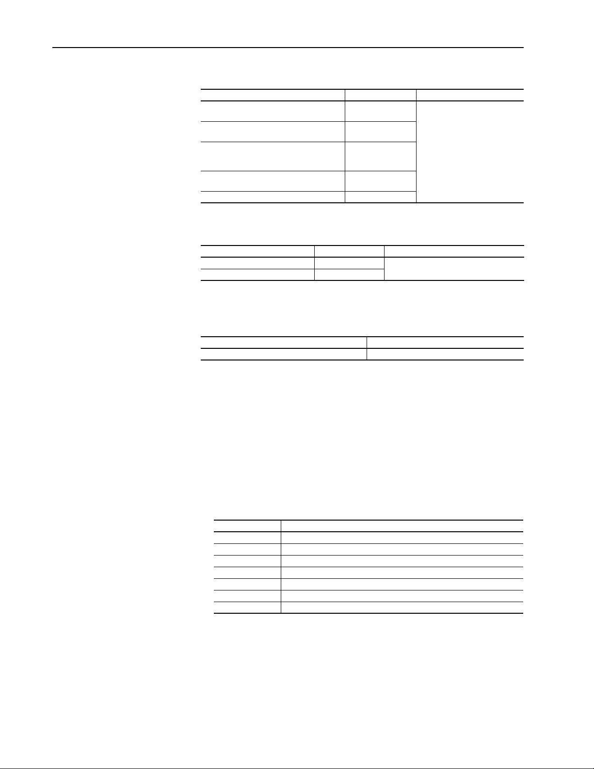
For information on … See page …
Who Should Use this Manual?
What Is Not in this Manual P-1
Reference Materials P-2
Manual Conventions P-2
General Precautions P-3
Compliance Certification P-3
Catalog Number Explanation P-4
P-1
This manual is intended for qualified personnel. You must be able to
program and operate Adjustable Frequency AC Drive devices. In addition,
you must have an understanding of the parameter settings and functions.
What Is Not in this Manual
The PowerFlex 40 Adjustable Frequency AC Standard Configured Drives
Installation Instructions is designed to provide only basic installation and
operation information. For this reason, the following topics have not been
included:
• Troubleshooting
• Start-Up
• Programming and Parameters
Please refer to the PowerFlex 40 User Manual for detailed drive
information.
Publication 23B-IN001G
Page 6
P-2 Overview
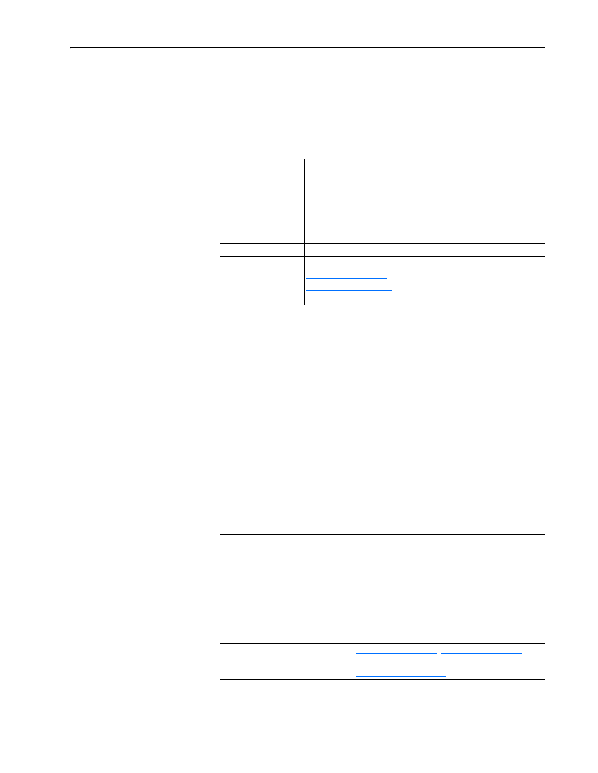
Reference Materials
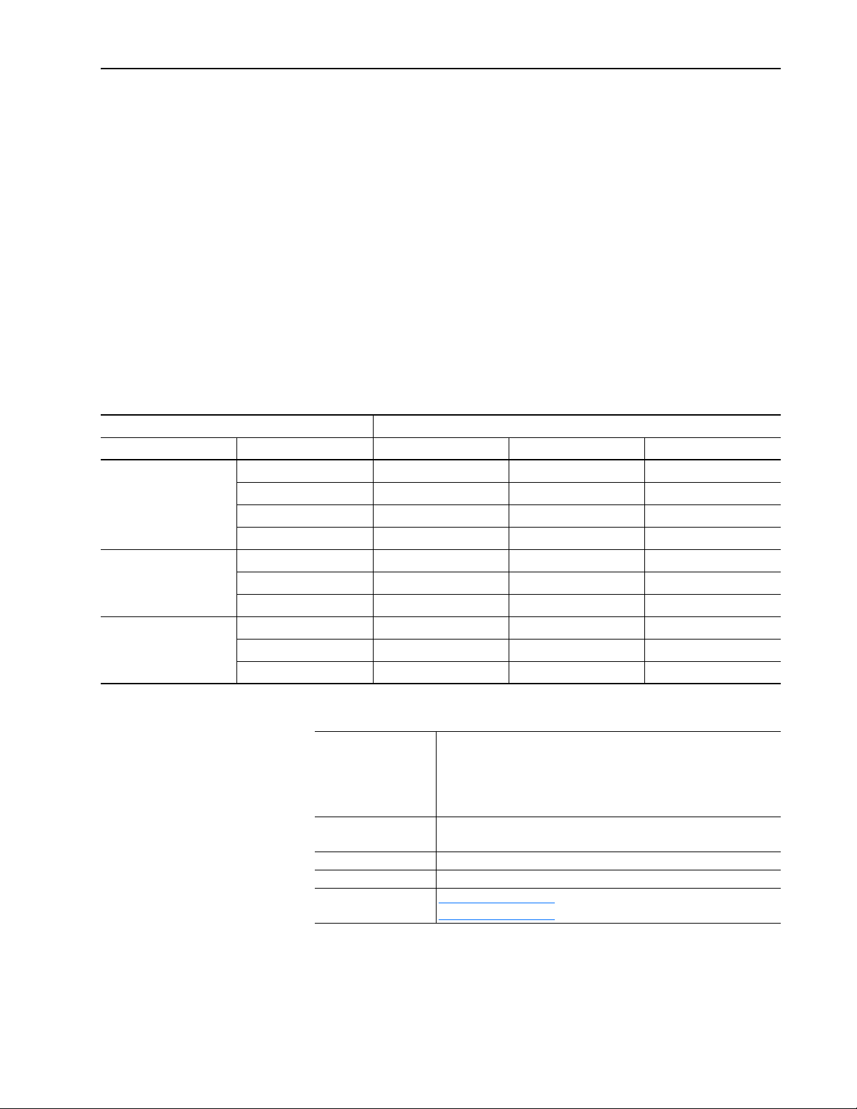
The following manuals are recommended for general drive information:
Title Publication Available Online at …
Wiring and Grounding Guidelines for Pulse
Width Modulated (PWM) AC Drives
Preventive Maintenance of Industrial Control
and Drive System Equipment
Safety Guidelines for the Application,
Installation and Maintenance of Solid State
Control
A Global Reference Guide for Reading
Schematic Diagrams
Guarding Against Electrostatic Damage 8000-4.5.2
DRIVES-IN001…
DRIVES-TD001…
SGI-1.1
0100-2.10
www.rockwellautomation.com/
literature
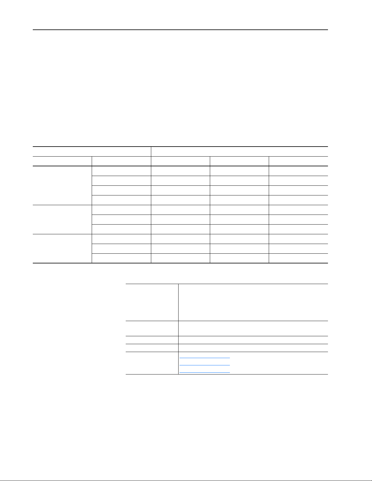
For detailed PowerFlex 40 information including drive parameters,
programming, start-up, troubleshooting, specifications:
Title Publication Available Online at …
PowerFlex 40 User Manual 22B-UM001…
PowerFlex Reference Manual PFLEX-RM001…
www.rockwellautomation.com/literature
The latest version of this Installation Instructions can be obtained online at …
www.rockwellautomation.com/literature
For Allen-Bradley Drives Technical Support:
Title Online at …
Allen-Bradley Drives Technical Support www.ab.com/support/abdrives
Manual Conventions
• To help differentiate parameter names and LCD display text from other
text, the following conventions will be used:
– Parameter Names will appear in [brackets].
For example: [DC Bus Voltage].
– Display Text will appear in “quotes.” For example: “Enabled.”
• The following words are used throughout the manual to describe an
action:
Word Me aning
Can Possible, able to do something
Cannot Not possible, not able to do something
May Permitted, allowed
Must Unavoidable, you must do this
Shall Required and necessary
Should Recommended
Should Not Not recommended
Publication 23B-IN001G
Page 7
General Precautions
Overview P-3
ATTENTION: This drive contains ESD (Electrostatic
Discharge) sensitive parts and assemblies. Static control
!
precautions are required when installing, testing, servicing or
repairing this assembly. Component damage may result if ESD
control procedures are not followed. If you are not familiar with
static control procedures, reference A-B publication 8000-4.5.2,
“Guarding Against Electrostatic Damage” or any other applicable
ESD protection handbook.
ATTENTION: An incorrectly applied or installed drive can
result in component damage or a reduction in product life. Wiring
!
or application errors, such as, undersizing the motor, incorrect or
inadequate AC supply, or excessive ambient temperatures may
result in malfunction of the system.
ATTENTION: Only qualified personnel familiar with adjustable
frequency AC drives and associated machinery should plan or
!
implement the installation, start-up and subsequent maintenance
of the system. Failure to comply may result in personal injury
and/or equipment damage.
Compliance Certification
ATTENTION: To avoid an electric shock hazard, verify that the
voltage on the bus capacitors has discharged before performing
!
any work on the drive. Measure the voltage at the drive (Refer to
the PowerFlex 40 User Manual for test point locations). The
voltage must be zero.
Certifications are applicable to approved program defined options.
U.S./Canada UL: UL508C
CUL: CAN/CSA-C22.2 No. 14
Please refer to the PowerFlex 40 User Manual, publication 22B-UM001,
for additional information.
Publication 23B-IN001G
Page 8
P-4 Overview
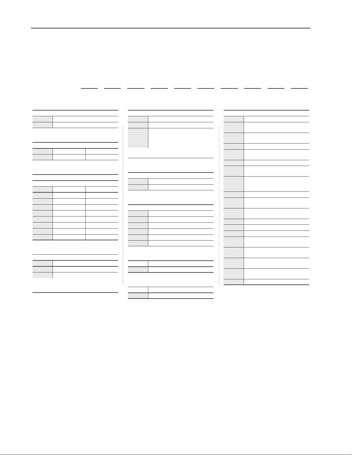
Catalog Number Explanation
1-3 4 56-8 9 10111213141516+
23B –
D 4P0 D 1 0 4 N N – P6
The PowerFlex 40 Adjustable Frequency AC Standard Configured Drives
catalog numbering scheme is shown below.
Position
abcdefghi j
a
Drive
Code Type
23B PowerFlex 40
b
Voltage Rating
Code Voltage Ph.
D 480V ac 3
c
Amp Rating
480V 60Hz Input
Code Amps kW (Hp)
1P4 1.4 0.4 (0.5)
2P3 2.3 0.75 (1.0)
4P0 4.0 1.5 (2.0)
6P0 6.0 2.2 (3.0)
010 10.5 4.0 (5.0)
012 12 5.5 (7.5)
017 17 7.5 (10)
024 24 11 (15)
d
Enclosure
Code Enclosure
C NEMA/UL Type 4X ‡
D NEMA/UL Type 4 ‡
‡ The design of the PowerFlex 40 Standard
Configured Drive supports indoor and outdoor
applications that are not in direct sunlight.
Code Interface Module
1 Fixed Keypad on Drive
Display with Digital Speed Control
F
This option changes the enclosure rating to
indoor only.
Code Rating
0 Not Filtered
Code Version
4 RS485 (Standard)
C ControlNet
D DeviceNet
E EtherNet/IP
P PROFIBUS DP
Code Rating
N Reserved
Code Rating
N Reserved
e
HIM
Fixed Keypad on Drive and LCD
HIM on Enclosure Door
(22-HIM-C2S)
f
Emission Class
g
Version
h
i
j
Options
Code Description
-E22
-E23
-P3 Motor Circuit Protector
-P3T
-P6 Disconnect Switch - Fused
-P6T
-R3
-R4 DeviceNet Point I/O w/IB4 (4 Inputs)
-R5
-S1
-S4 Auto/Manual S.S. (Speed Ref.)
-S7 Start and Stop P.B.
-S8 Forward/Reverse S.S.
-S18
-S20
-S21
-S22
-S23 Clear Fault P.B.
DeviceNet Quick Disconnect
(Bottom)
DeviceNet Quick Disconnect (Left
Side)
Motor Circuit Protector (Customer
wiring into top of device)
Disconnect Switch - Fused
(Customer wiring into top of device)
DeviceNet I/O (4 In/2 Out) w/Spring
Return HOA and Power Disconnect
Aux. Contact
-R3 plus 4 I/O Quick Disconnects
and (1) 24V DC Receptacle
Hand/Off/Auto S.S.
(Start/Stop/Speed Ref.)
Door Mounted Local Speed Pot (1-
Tur n )
Local/Remote and Local Control
Off/Run Forward Selector Switches
Local/Off/Remote with 1 N.O.
Interposing Relay
Spring Return Hand/Off Auto S.S.
(Start/Stop/Speed Ref.)
Publication 23B-IN001G
Page 9

Chapter 1
PowerFlex 40 Standard Configured Drive Standard Features and Options
Chapter Objectives
Standard Features
This chapter describes the standard features and operation for PowerFlex 40
Standard Configured Drives and associated options.
For information on … See page …
Standard Features
Enclosure Options 1-2
Communication Options 1-3
Power Disconnect Options 1-4
Operator Device Options 1-9
Quick Disconnects 1-15
I/O Options 1-16
This package integrates the Standard PowerFlex 40 drive. The PowerFlex
40 drive can be used for Volts per hertz or Sensorless Vector applications
and offers an Autotune feature allowing the drive to adapt to individual
motor characteristics.
The PowerFlex 40 is assembled in an enclosure which includes the
following features…
• NEMA/UL Type 4/4X - indoor and outdoor applications other than
direct sunlight.
• Flange mount drive/external heatsink reducing overall enclosure size.
(1)
1-1
• Mounting feet - orientation is adjustable per customer requirements.
If required, the drive can be removed from the front of the enclosure for
ease of assembly or repair.
Low cost, highly configurable I/O inputs and/or 0-10V/4-20 mA outputs
that are not used by program standard features and options are available for
customer use.
(1)
The enclosure does not normally protect electrical equipment from
condensation, corrosion or contamination, which may occur within the
enclosure or enter via the conduit or unsealed openings. Users must
make adequate provisions to safeguard against such conditions, and
satisfy themselves that the equipment is properly protected. For further
information on criteria associated with NEMA enclosure ratings, refer to
NEMA standards Publication No. 250-1991. When optional Door
Mounted HIM is supplied, enclosure is rated indoor only. See enclosure
options for specific enclosure style quoted.
Publication 23B-IN001G
Page 10

1-2 PowerFlex 40 Standard Configured Drive Standard Features and Options
Enclosure Options
NEMA/UL Type 4 (Position 9, Code D)
The enclosure provided is a NEMA/UL Type 4, painted mild steel, which
supports both NEMA/UL Type 4 and NEMA/UL Type 12 applications.
Type 4 enclosures are intended for indoor or outdoor use primarily to
provide a degree of protection against windblown dust and rain, splashing
water, and hose directed water, and to be undamaged by the formation of ice
on the enclosure. They are designed to meet hose-down, dust, and external
icing and rust resistance design tests. Doors and openings will be gasket
sealed. There are no ventilation openings within the enclosure to allow for
free exchange of inside and outside air.
Note: If optional Door Mounted HIM is not supplied, the design of the
PowerFlex 40 Standard Configured Drive supports indoor and outdoor
applications that are not in direct sunlight.
NEMA/UL Type 4X (Position 9, Code C)
The enclosure provided is a NEMA/UL Type 4X. The material is type 304
stainless steel. Type 4X enclosures are intended for indoor or outdoor use
primarily to provide a degree of protection against corrosion, windblown
dust and rain, splashing water, and hose directed water, and to be
undamaged by the formation of ice on the enclosure. They are designed to
meet hose-down, dust, and external icing and rust resistance design tests.
Doors and openings will be gasket sealed. There are no ventilation openings
within the enclosure to allow for free exchange of inside and outside air.
Note: If optional Door Mounted HIM is not supplied, the design of the
PowerFlex 40 Standard Configured Drive supports indoor and outdoor
applications that are not in direct sunlight.
Publication 23B-IN001G
Page 11

PowerFlex 40 Standard Configured Drive Standard Features and Options 1-3
Communication Options
DeviceNet (Position 12, Code D)
The DeviceNet option is drive mounted and consists of the DeviceNet
communication adaptor (22-COMM-D) and adaptor cover (22B-CCB for
frame B drives or 22B-CCC for frame C drives). When DeviceNet is
present, no other communication option is available other than the HIM.
When used as a slave, the HIM will have limited functionality. For details
related to the DeviceNet option, refer to the PowerFlex DeviceNet Adapter
User Manual, publication 22COMM-UM003….
To review this schematic see
Figure 2.1 on page 2-2 and Figure 2.3 on page 2-4.
EtherNet/IP (Position 12, Code E)
The EtherNet/IP option is drive mounted and consists of the EtherNet/IP
communication adaptor (22-COMM-E) and adaptor cover (22B-CCB for
frame B drives or 22B-CCC for frame C drives). When EtherNet/IP is
present, no other communications option is available other than the HIM.
When used as a slave, the HIM will have limited functionality. For details
related to the EtherNet/IP option, refer to the PowerFlex EtherNet/IP
Adapter User Manual, publication 22COMM-UM004….
To review this schematic see
Figure 2.1 on page 2-2 and Figure 2.3 on page 2-4.
PROFIBUS (Position 12, Code P)
The PROFIBUS option is drive mounted and consists of the PROFIBUS
communication adaptor (22-COMM-P) and adaptor cover (22B-CCB for
frame B drives or 22B-CCC for frame C drives). When PROFIBUS is
present, no other communication option is available other than the HIM.
When used as a slave, the HIM will have limited functionality. For details
related to PROFIBUS option, refer to the PowerFlex PROFIBUS Adapter
User Manual, publication 22COMM-UM005….
To review this schematic see
Figure 2.1 on page 2-2 and Figure 2.3 on page 2-4.
ControlNet (Position 12, Code C)
The ControlNet option is drive mounted and consists of the ControlNet
communication adaptor (22-COMM-C) and adaptor cover (22B-CCB for
frame B drives or 22B-CCC for frame C drives). When ControlNet is
present, no other communication option is available other than the HIM.
When used as a slave, the HIM will have limited functionality. For details
related to ControlNet option, refer to the PowerFlex ControlNet Adapter
User Manual, publication 22COMM-UM006….
To review this schematic see
Figure 2.1 on page 2-2 and Figure 2.3 on page 2-4.
Publication 23B-IN001G
Page 12

1-4 PowerFlex 40 Standard Configured Drive Standard Features and Options
Power Disconnect Options
Drive Motor Circuit Protector (Position 16+, Code -P3)
The Drive Motor Circuit Protector option is factory installed and provides a
manual means of disconnecting input power to the drive. The Allen-Bradley
Bulletin 140M switch is designed to meet short circuit requirements for
branch circuit protection. The rotary style handle is padlockable in On or
Off position. This option has a 65 kA short circuit withstand rating. Over
load protection is supplied by the drive not the motor circuit protector.
Incoming customer supplied power cables terminate at terminals R, S, T
(L1, L2, L3) located on the bottom of the device.
Component Specifications
Switch A-B Bulletin 140M, 480V, 65 kA short circuit withstand rating
3-pole, Rod operated
UL listed, CE Approved, CSA Certified
Handle Rotary style handle through the door, Door interlocked
Padlockable in On or Off position, Defeatable in the On position
IP66 (Type 3R, 3, 12, 4, 4X)
Drive Motor Circuit Protector (Position 16+, Code -P3T)
The Drive Motor Circuit Protector option is factory installed and provides a
manual means of disconnecting input power to the drive. The Allen-Bradley
Bulletin 140M switch is designed to meet short circuit requirements for
branch circuit protection. The rotary style handle is padlockable in On or
Off position. This option has a 65 kA short circuit withstand rating. Over
load protection is supplied by the drive not the motor circuit protector.
Incoming customer supplied power cables terminate at terminals R, S, T
(L1, L2, L3) located on the top of the device.
Component Specifications
Switch A-B Bulletin 140M, 480V, 65 kA short circuit withstand rating
3-pole, Rod operated
UL listed, CE Approved, CSA Certified
Handle Rotary style handle through the door, Door interlocked
Padlockable in On or Off position, Defeatable in the On position
IP66 (Type 3R, 3, 12, 4, 4X)
Publication 23B-IN001G
Page 13

PowerFlex 40 Standard Configured Drive Standard Features and Options 1-5
Drive Input Fused Disconnect Switch (Position 16+, Code -P6)
The Drive Input Fused Disconnect Switch option is factory installed and
provides a manual means of disconnecting input power to the drive. The
Allen-Bradley Bulletin 194R switch is designed to meet disconnect switch
requirements for branch circuit protection. The rotary style handle is
padlockable in On or Off position. This option has a 100 kA short circuit
withstand rating. Class J fuses are supplied with the disconnect switch.
Incoming customer supplied power cables terminate at terminals R, S, T
(L1, L2, L3) located on the bottom of the device.
Component Specifications
Switch A-B Bulletin 194R, 600V, 100 kA short circuit withstand rating
Integral class J fuses, Captive terminal clamps
3-pole, Rod operated
UL listed, CE Approved, CSA, ASTA, and LOVAG Certified
Handle Rotary style handle through the door, Door interlocked
Padlockable in On or Off position, Defeatable in the On position
True switch status indication
IP66 (Type 3R, 3, 12, 4, 4X)
Drive Input Fused Disconnect Switch (Position 16+, Code -P6T)
The Drive Input Fused Disconnect Switch option is factory installed and
provides a manual means of disconnecting input power to the drive. The
Allen-Bradley Bulletin 194R switch is designed to meet disconnect switch
requirements for branch circuit protection. The rotary style handle is
padlockable in On or Off position. This option has a 100 kA short circuit
withstand rating. Class J fuses are supplied with the disconnect switch.
Incoming customer supplied power cables terminate at terminals R, S, T
(L1, L2, L3) located on the top of the device.
Component Specifications
Switch A-B Bulletin 194R, 600V, 100 kA short circuit withstand rating
Integral class J fuses, Captive terminal clamps
3-pole, Rod operated
UL listed, CE Approved, CSA, ASTA, and LOVAG Certified
Handle Rotary style handle through the door, Door interlocked
Padlockable in On or Off position, Defeatable in the On position
True switch status indication
IP66 (Type 3R, 3, 12, 4, 4X)
Publication 23B-IN001G
Page 14
1-6 PowerFlex 40 Standard Configured Drive Standard Features and Options
Main Fuses (F1-F3)
ATTENTION: Most codes require that upstream branch circuit
protection be provided to protect input power wiring. Install the
!
fuses recommended in Table 1.A
Failure to observe this precaution could result in damage to, or
destruction of, the equipment.
Input line branch circuit protection fuses must be used to protect the input
power lines. If input fuses are not provided with your drive, recommended
fuse values are shown in Table 1.A
1.A are applicable for one drive per branch circuit. No other load may be
applied to that fused circuit.
The recommended fuse type for all PowerFlex 40 Standard Configured
Drives is UL Class J.
Table 1.A Branch Fusing
Voltage Rating Drive Rating HP Fuse Rating Amps
480V AC 0.5 3
1.0 6
2.0 10
3.0 15
5.0 20
7.5 25
10 30
15 50
. Do not exceed the fuse ratings.
. The input fuse ratings listed in Tabl e
Publication 23B-IN001G
Page 15

PowerFlex 40 Standard Configured Drive Standard Features and Options 1-7
Input Power Wiring
Refer to the PowerFlex 40 User Manual for additional detailed information
about input power wiring recommendations and selection.
ATTENTION: Protect the contents of the options cabinet from
metal chips and other debris while drilling the conduit openings.
!
Failure to observe this precaution could result in damage to, or
destruction of, the equipment.
ATTENTION: Do not route signal and control wiring with
power wiring in the same conduit. This can cause interference
!
with drive operation. Failure to observe this precaution could
result in damage to, or destruction of, the equipment.
To connect AC input power to the drive package:
❏ 1. Select the proper wire size according to NEC and all applicable local
codes and standards. Note that you must punch openings in the Option
Cabinet of the desired conduit size, following NEC and all applicable
local codes and standards. Power terminal block specifications are listed
in Table 1.B
.
❏ 2. Connect the three-phase AC input power leads (three-wire VAC) to the
appropriate terminals. Connect the AC input power leads to terminals
L1, L2, L3 on the fused disconnect switch or motor circuit protector.
Note: Drive Input Fused Disconnect Switch (-P6) and Drive Motor
Circuit Protector (-P3) options are bottom fed. Drive Input Fused
Disconnect Switch (-P6T) and Drive Motor Circuit Protector (-P3T)
options are top fed.
❏ 3. Tighten the AC input terminal power terminals to the proper torque
according to drive type as shown in Table 1.B
Table 1.B Component Current Ratings and Wire Sizing
PowerFlex 40 SPD Drive Rating - 480V
HP Continuous
Current Rating
Amps
0.5-3 30 2.5 mm
5-7.5 30 3.5 mm
10-15 60 4.0 mm
(1)
Wire is Black Hypalon.
(2)
Maximum/minimum sizes that the terminal block will accept - these are not recommendations.
Factory Power
Wire Size
(14 AWG)
(12 AWG)
(10 AWG)
(1)(2)
2
2
2
.
Customer
Terminal Wire
Size
2.5-8.4 mm
(14-8 AWG)
2.5-8.4 mm
(14-8 AWG)
2.5-16.0 mm
(14-4 AWG)
2
2
2
Operating Torque
4.0 N-m
(35 lb.-in.)
4.0 N-m
(35 lb.-in.)
4.0 N-m
(35 lb.-in.)
Publication 23B-IN001G
Page 16
1-8 PowerFlex 40 Standard Configured Drive Standard Features and Options
Output Power Wiring
Refer to the PowerFlex 40 User Manual for additional detailed information
about output power wiring recommendations and selection.
ATTENTION: Unused wires in conduit must be grounded at
both ends to avoid a possible shock hazard caused by induced
!
voltages. Also, if a drive sharing a conduit is being serviced or
installed, all drives using this conduit should be disabled to
eliminate the possible shock hazard from cross-coupled motor
leads. Failure to observe these precautions could result in bodily
injury.
ATTENTION: Do not route signal and control wiring with
power wiring in the same conduit. This can cause interference
!
with drive operation. Failure to observe this precaution could
result in damage to, or destruction of, the equipment.
To connect AC output power wiring from the drive to the motor:
❏ 1. Wire the three-phase AC output power motor leads by routing them
according to the drive option type. Note that you must punch openings in
the option cabinet of the desired conduit size, following NEC and all
applicable local codes and standards. Power terminal block
specifications are listed in Table 1.C
.
Do not route more than three sets of motor leads through a single
conduit. This will minimize cross-talk that could reduce the effectiveness
of noise reduction methods. If more than three drive/motor connections
per conduit are required, shielded cable must be used. If possible, each
conduit should contain only one set of motor leads.
❏ 2. Connect the three-phase AC output power motor leads to terminals
U, V, W (T1, T2, T3) on the power terminal block located on the drive.
❏ 3. Tighten the three-phase AC output power terminals to the proper torque
according to drive type as shown in Table 1.C
Table 1.C AC Output Power Terminal Block Specifications
Frame Maximum Wire Size
2
B 5.3 mm
C 8.4 mm
(1)
Maximum/minimum sizes that the terminal block will accept - these are not recommendations.
(10 AWG) 1.3 mm2 (16 AWG) 1.7-2.2 N-m (16-19 lb.-in.)
2
(8 AWG) 1.3 mm2 (16 AWG) 2.9-3.7 N-m (26-33 lb.-in.)
(1)
Minimum Wire Size Recommended Torque
.
Publication 23B-IN001G
Page 17
PowerFlex 40 Standard Configured Drive Standard Features and Options 1-9
Operator Device Options
Hand/Off/Auto Selector Switch (Position 16+, Code S1)
This 800F door mounted operator device is factory installed and provides a
Hand/Off/Auto selector switch.
The Hand/Off/Auto selector switch will start the drive in Hand mode and
stop the drive in Off mode. In Auto mode the drive will be stopped and
started from remote contact closures. In all cases, the Stop input to the drive
must be present before the drive will start.
The Hand/Off/Auto selector switch also determines the source of the
actual drive speed reference. In Hand mode, speed source is parameter
A072 [Preset Freq 2]. In Auto mode, speed source is parameter A071
[Preset Freq 1].
If the door mounted speed potentiometer (Option S18) is supplied and it is
intended to be the speed reference in Hand mode, set parameter A052
[Digital In2 Sel] to option 13 “10V In Ctrl”. Refer to the table below and the
PowerFlex 40 User Manual, publication 22B-UM001, for other options.
Hand/Off/Auto Selector Switch (Code S1)
Speed Reference Parameter Settings
Hand Mode Auto Mode P038 [Speed Reference] A051 [Digital In1 Sel] A052 [Digital In2 Sel]
Preset Speed Preset Speed 4 “Preset Freq” 4 “Preset Freq” 4 “Preset Freq”
Analog Input (0-10V) 4 “Preset Freq” 13 “10V In Ctrl” 4 “Preset Freq”
Analog Input (4-20mA) 4 “Preset Freq” 14 “20mA In Ctrl” 4 “Preset Freq”
Communication Port
Speed Pot (Door) Preset Speed 4 “Preset Freq” 4 “Preset Freq” 13 “10V In Ctrl”
Analog Input (4-20mA) 4 “Preset Freq” 14 “20mA In Ctrl” 13 “10V In Ctrl”
Communication Port
HIM (Door) Preset Speed 4 “Preset Freq” 4 “Preset Freq” 6 “Comm Port”
Analog Input (0-10V) 4 “Preset Freq” 13 “10V In Ctrl” 6 “Comm Port”
Analog Input (4-20mA) 4 “Preset Freq” 14 “20mA In Ctrl” 6 “Comm Port”
(1)
Communication port will have both logic and reference control.
(1)
4 “Preset Freq” 6 “Comm Port” 4 “Preset Freq”
(1)
4 “Preset Freq” 6 “Comm Port” 13 “10V In Ctrl”
Component Specifications
Bulletin 800F
Devices
IEC style, Internationally rated
Meet IP65/IP66 and NEMA/UL Type 4/4X/13
UL Listed, CSA Certified
10 amp contacts
2
(22–12 AWG) maximum
Hand/Off/Auto
Selector Switch
Screw terminals, 0.3–3.5 mm
3 position, Maintained
4 N.O. contacts
Legend Plate 30 x 50 mm, Black with white lettering
Wiring 0.8 mm
2
(18 AWG), Blue
Schematics Figure 2.4 on page 2-5
Figure 2.5 on page 2-6
This option is not compatible with Codes R3, R5, S4, S7, S20, S21 or S22.
Publication 23B-IN001G
Page 18
1-10 PowerFlex 40 Standard Configured Drive Standard Features and Options
Auto/Manual Selector Switch (Position 16+, Code S4)
This 800F door mounted operator device is factory installed and provides an
Auto/Manual selector switch.
The Auto/Manual selector switch determines the source of the actual drive
speed reference. Using 2-wire control in Auto mode, speed source is
parameter A071 [Preset Freq 1]. In Manual mode, the speed source is
parameter A072 [Preset Freq 2].
If the door mounted speed potentiometer (Option S18) is supplied and it is
intended to be the speed reference in Manual mode, set parameter P052
[Digital In2 Sel] to option 13 “10V In Ctrl”. Refer to the table below and the
PowerFlex 40 User Manual, publication 22B-UM001, for other options.
Auto/Manual Selector Switch (Code S4)
Speed Reference Parameter Settings
Manual Mode Auto Mode P038 [Speed Reference] A051 [Digital In1 Sel] A052 [Digital In2 Sel]
Preset Speed Preset Speed 4 “Preset Freq” 4 “Preset Freq” 4 “Preset Freq”
Analog Input (0-10V) 4 “Preset Freq” 13 “10V In Ctrl” 4 “Preset Freq”
Analog Input (4-20mA) 4 “Preset Freq” 14 “20mA In Ctrl” 4 “Preset Freq”
Communication Port
Speed Pot (Door) Preset Speed 4 “Preset Freq” 4 “Preset Freq” 13 “10V In Ctrl”
Analog Input (4-20mA) 4 “Preset Freq” 14 “20mA In Ctrl” 13 “10V In Ctrl”
Communication Port
HIM (Door) Preset Speed 4 “Preset Freq” 4 “Preset Freq” 6 “Comm Port”
Analog Input (0-10V) 4 “Preset Freq” 13 “10V In Ctrl” 6 “Comm Port”
Analog Input (4-20mA) 4 “Preset Freq” 14 “20mA In Ctrl” 6 “Comm Port”
(1)
Communication port will have both logic and reference control.
(1)
4 “Preset Freq” 6 “Comm Port” 4 “Preset Freq”
(1)
4 “Preset Freq” 6 “Comm Port” 13 “10V In Ctrl”
Component Specifications
Bulletin 800F
Devices
IEC style, Internationally rated
Meet IP65/IP66 and NEMA/UL Type 4/4X/13
UL Listed, CSA Certified
10 amp contacts
2
(22–12 AWG) maximum
Auto/Manual
Selector Switch
Screw terminals, 0.3–3.5 mm
2 position, Maintained
1 N.C. contact
Legend Plate 30 x 50 mm, Black with white lettering
Wiring 0.8 mm
2
(18 AWG), Blue
Schematics Figure 2.6 on page 2-7
Figure 2.7 on page 2-8
Figure 2.8 on page 2-9
This option is not compatible with Codes R3, R5, S1, S20, S21 or S22.
Publication 23B-IN001G
Page 19
PowerFlex 40 Standard Configured Drive Standard Features and Options 1-11
Start and Stop Push Buttons (Position 16+, Code S7)
This option provides factory installed 800F Start and Stop push buttons.
In all cases, the Stop input to the drive must be present before the drive will
start. Using 3-wire control, speed source is parameter A070 [Preset Freq 0].
The Stop push button may also be used as a fault reset.
Component Specifications
Bulletin 800F
Devices
Start Push Button Flush head, Green, 1 N.O. contact
Stop Push Button Extended head, Red, 1 N.C. contact
Legend Plate 30 x 50 mm, Black with white lettering
Wiring 0.8 mm
Schematics Figure 2.7 on page 2-8
This option is not compatible with Codes R3, R5, S1, S20, S21, S22 or S23.
IEC style, Internationally rated
Meet IP65/IP66 and NEMA/UL Type 4/4X/13
UL Listed, CSA Certified
10 amp contacts
Screw terminals, 0.3–3.5 mm
2
(18 AWG), Blue
Figure 2.9 on page 2-10
Figure 2.10 on page 2-11
2
(22–12 AWG) maximum
Forward/Reverse Selector Switch (Position 16+, Code S8)
This 800F door mounted operator device is factory installed and provides a
Forward/Reverse selector switch.
When configured for 2-wire control, the drive will start when the selector
switch is set to Forward. When the selector switch is set to Reverse, the
drive will run in reverse. If the selector switch is operated while the drive is
running, a change of direction command will occur. If the drive is stopped
and the selector switch is operated, a change of direction command will
occur. The speed source is parameter P070 [Preset Freq 0].
When configured for 3-wire control (Code S7 with S8), the selector switch
only changes direction. The drive is started and stopped via the Start and
Stop push buttons (Code S7).
Component Specifications
Bulletin 800F
Devices
Forward/Reverse
Selector Switch
Legend Plate 30 x 50 mm, Black with white lettering
Wiring 0.8 mm
Schematics 2-Wire Control: Figure 2.5 on page 2-6
IEC style, Internationally rated
Meet IP65/IP66 and NEMA/UL Type 4/4X/13
UL Listed, CSA Certified
10 amp contacts
Screw terminals, 0.3–3.5 mm
2-Wire: 2 position, Maintained, 1 N.O. & 1 N.C. contacts
3-Wire: 2 position, Maintained, 1 N.C. contact
2
(18 AWG), Blue
Figure 2.11 on page 2-12
3-Wire Control: Figure 2.10 on page 2-11
2
(22–12 AWG) maximum
, Figure 2.8 on page 2-9,
This option is not compatible with Codes R3, R5, S20 or S21.
Publication 23B-IN001G
Page 20

1-12 PowerFlex 40 Standard Configured Drive Standard Features and Options
Local Speed Potentiometer (Code S18)
This option provides a factory installed 800F door mounted one turn
potentiometer for speed control. The device provides the speed source when
no digital inputs are active.
When this option is provided, it becomes the speed source for the Hand
mode of the Hand/Off/Auto selector switch (Option S1) and the Manual
mode of the Auto/Manual selector switch (Option S4).
Component Specifications
Bulletin 800F
Devices
Speed Potentiometer 1-turn, 10k, 2.25W, 500V
Legend Plate 30 x 50 mm, Black with white lettering
Wiring 0.8 mm
Schematic Figure 2.13 on page 2-14
This option is not compatible with Codes R3-R5.
IEC style, Internationally rated
Meet IP65/IP66 and NEMA/UL Type 4/4X/13
UL Listed, CSA Certified
Screw terminals, 0.3–3.5 mm
2
(18 AWG), Blue
2
(22–12 AWG) maximum
Local Control Off/Run Forward and Local/Remote Selector Switches
(Code S20)
This option provides two factory installed 800F door mounted selector
switches. The Local/Remote selector switch determines the source of the
start, stop, speed and direction commands. In Local mode, the factory
default setting for parameter P038 [Speed Reference] = 4 “Preset Freq.”
In Remote mode, the factory default setting for parameter A051 [Digital In1
Sel] = 6 “Comm Port.” The Off/Run Forward selector switch allows the
drive to be started and stopped when in Local Control.
Component Specifications
Bulletin 800F Devices IEC style, Internationally rated
Meet IP65/IP66 and NEMA/UL Type 4/4X/13
UL Listed, CSA Certified
10 amp contacts
Screw terminals, 0.3–3.5 mm
Local Control Off/Run
Forward Selector Switch
Local/Remote
Selector Switch
Legend Plate 30 x 50 mm, Black with white lettering
Wiring 0.8 mm
Schematic Figure 2.12 on page 2-13
2 position, Maintained, 1 N.O. contact
2 position, Maintained, 1 N.O. contact
2
(18 AWG), Blue
2
(22–12 AWG) maximum
Publication 23B-IN001G
This option is not compatible with Codes R3, R5, S1, S4, S7, S8, S21 or
S22.
Page 21

PowerFlex 40 Standard Configured Drive Standard Features and Options 1-13
Local/Off/Remote Selector Switch With One Normally Open Interposing
Relay (Code S21)
This 800F door mounted operator device and interposing relay option is
factory installed and provides a Local/Off/Remote selector switch.
The Local/Off/Remote selector switch will start the drive in Local mode and
stop it in Off mode. In Remote mode, the drive will be stopped and started
from the factory installed CR1 contact which is energized by a customer
supplied and protected 120V AC source. In all cases, the Stop input to the
drive must be present before the drive will start.
In both Local and Remote modes, the speed source is parameter A070
[Preset Freq 0].
Component Specifications
Bulletin 800F
Devices
Local/Off/Remote
Selector Switch
Interposing Control
Relay
Legend Plate 30 x 50 mm, Black with white lettering
Wiring 0.8 mm
Schematic Figure 2.14 on page 2-15
IEC style, Internationally rated
Meet IP65/IP66 and NEMA/UL Type 4/4X/13
UL Listed, CSA Certified
10 amp contacts
Screw terminals, 0.3–3.5 mm
3 position, Maintained, 2 N.O. contacts
1 relay, 10 amp, 120V AC coil, Octal base
2
(18 AWG), Blue
2
(22–12 AWG) maximum
This option is not compatible with Codes R3, R5, S1, S4, S7, S8, S20 or
S22.
Publication 23B-IN001G
Page 22

1-14 PowerFlex 40 Standard Configured Drive Standard Features and Options
Spring Return Hand-Off-Auto Selector Switch (Code S22)
This 800F door mounted operator device is factory installed and provides a
Hand/Off/Auto selector switch. The Hand position is equipped with a spring
return.
The Hand/Off/Auto selector switch will start the drive while held in Hand
mode and stop the drive in Off mode. The selector switch has a spring return
disallowing the operator to remain in Hand. In Auto mode the drive will be
stopped and started from remote contact closures. In all cases, the Stop
input to the drive must be present before the drive will start.
The Hand/Off/Auto selector switch also determines the source of the actual
drive speed reference. In Hand mode, speed source is parameter A072
[Preset Freq 2]. In Auto mode, speed source is parameter A071 [Preset Freq
1].
If the door mounted speed potentiometer (Option S18) is supplied and it is
intended to be the speed reference in Hand mode, set parameter A052
[Digital In2 Sel] to option 13 “10V In Ctrl.”
Spring Return HOA Selector Switch (Code S22)
Speed Reference Parameter Settings
Hand Mode Auto Mode P038 [Speed Reference] A051 [Digital In1 Sel] A052 [Digital In2 Sel]
Preset Speed Preset Speed 4 “Preset Freq” 4 “Preset Freq” 4 “Preset Freq”
Analog Input (0-10V) 4 “Preset Freq” 13 “10V In Ctrl” 4 “Preset Freq”
Analog Input (4-20mA) 4 “Preset Freq” 14 “20mA In Ctrl” 4 “Preset Freq”
Communication Port
Speed Pot (Door) Preset Speed 4 “Preset Freq” 4 “Preset Freq” 13 “10V In Ctrl”
Analog Input (4-20mA) 4 “Preset Freq” 14 “20mA In Ctrl” 13 “10V In Ctrl”
Communication Port
HIM (Door) Preset Speed 4 “Preset Freq” 4 “Preset Freq” 6 “Comm Port”
Analog Input (0-10V) 4 “Preset Freq” 13 “10V In Ctrl” 6 “Comm Port”
Analog Input (4-20mA) 4 “Preset Freq” 14 “20mA In Ctrl” 6 “Comm Port”
(1)
Communication port will have both logic and reference control.
(1)
4 “Preset Freq” 6 “Comm Port” 4 “Preset Freq”
(1)
4 “Preset Freq” 6 “Comm Port” 13 “10V In Ctrl”
Publication 23B-IN001G
Component Specifications
Bulletin 800F
Devices
IEC style, Internationally rated
Meet IP65/IP66 and NEMA/UL Type 4/4X/13
UL Listed, CSA Certified
10 amp contacts
2
(22–12 AWG) maximum
Hand/Off/Auto
Selector Switch:
Screw terminals, 0.3–3.5 mm
3 position, Hand (spring return), Off, Auto (maintained), 4 N.O.
contacts
Legend Plate 30 x 50 mm, Black with white lettering
Wiring 0.8 mm
2
(18 AWG), Blue
Schematic Figure 2.16 on page 2-17
This option is not compatible with Codes R3, R5, S1, S4, S7, S20 or S21.
Page 23

PowerFlex 40 Standard Configured Drive Standard Features and Options 1-15
Clear Fault Push Button (Code S23)
This option provides a factory installed 800F Clear Fault push button.
Component Specifications
Bulletin 800F
Devices
Clear Fault Push
Button:
Legend Plate 30 x 50 mm, Black with white lettering
Wiring 0.8 mm
Schematic Figure 2.17 on page 2-18
This option is not compatible with Code S7.
IEC style, Internationally rated
Meet IP65/IP66 and NEMA/UL Type 4/4X/13
UL Listed, CSA Certified
10 amp contacts
Screw terminals, 0.3–3.5 mm
Flush head, Black, 1 N.O. contact
2
(18 AWG), Blue
2
(22–12 AWG) maximum
Quick Disconnects
DeviceNet Quick Disconnect - Bottom (Code E22)
A Brad Harrison, 5 pin, bulkhead, male receptacle is provided and wired to
the drive mounted DeviceNet module. The connector is located through the
bottom of the enclosure providing a quick disconnect. This option is
designed to enhance the DeviceNet offering (Position 12, Code D) and is
not compatible with options 4, C, E, P (Position 12), or E23.
To review schematic refer to
To review layout refer to
Figure 2.4 on page 2-5.
Figure 3.4 on page 3-4.
For NEMA/UL Type 4 or less stringent environments, the outer connector
construction is made of plastic designed to withstand washdown conditions.
DeviceNet Quick Disconnect - Left Side (Code E23)
A Brad Harrison, 5 pin, bulkhead, male receptacle is provided and wired to
the drive mounted DeviceNet module. The connector is located through the
left side of the enclosure providing a quick disconnect. This option is
designed to enhance the DeviceNet offering (Position 12, Code D) and is
not compatible with options 4, C, E, P (Position 12), or E22.
To review schematic refer to
To review layout refer to
Figure 2.4 on page 2-5.
Figure 3.4 on page 3-4.
For NEMA/UL Type 4 or less stringent environments the outer connector
construction is made of plastic designed to withstand washdown conditions.
Publication 23B-IN001G
Page 24

1-16 PowerFlex 40 Standard Configured Drive Standard Features and Options
I/O Options
DeviceNet I/O (4 In/2 Out) w/Spring Return HOA and Power Disconnect
Aux. Contact (Position 16+, Code R3)
This option provides a factory installed 800F door mounted operator device,
a 100-DNY42R and a power disconnect auxiliary contact mounted internal
to the cabinet.
The Hand/Off/Auto selector switch will start the drive while held in the
Hand mode and stop it in the Off mode. The default speed reference comes
from parameter P038, option 4 (Preset Freq). The selector switch has a
spring return disallowing the operator to remain in Hand. When in Auto the
default speed reference is derived parameter A051, option 4 (Preset Freq).
The 100-DNY42R is powered by DeviceNet and provides control based on
customer control parameters.
This option is prewired with an auto contact from the Hand/Off/Auto
selector switch between the I/O V+ and IN0 terminals. The main power
disconnect auxiliary contact is wired between the I/O V+ and IN1 terminals
indicating if the disconnect is on or off. Two inputs and two outputs are
available for customer use.
Component Specifications
Bulletin 800F
Devices
Hand/Off/Auto
Selector Switch
Legend Plate 30 x 50 mm, Black with white lettering
Wiring 0.8 mm
100-DNY42R cULus Listed, CSA, CE
Schematic Figure 2.18 on page 2-19
IEC style, Internationally rated
Meet IP65/IP66 and NEMA/UL Type 4/4X/13
UL Listed, CSA Certified
10 amp contacts
Screw terminals, 0.3–3.5 mm
3 position, Hand (spring return), Off, Auto (maintained)
3 N.O. & 3 N.C. contacts
2
(18 AWG), Blue
DeviceLogix™, Rotary address switches
24V DC or 120V AC inputs
High-Capacity transistor or Relay outputs
ODVA Compliance v2.0 Tested
Power Disconnect Auxiliary Contact
1 N.O. & 1 N.C. Side mounted contacts
2
(22–12 AWG) maximum
Publication 23B-IN001G
This option must be used with the drive mounted DeviceNet option D
(Position 12) and is not compatible with options R4, R5, S1, S4, S7, S8,
S20, S21 or S22. The drive mounted DeviceNet and the 100-DNY42R will
appear as separate nodes on the communication system.
Page 25

PowerFlex 40 Standard Configured Drive Standard Features and Options 1-17
DeviceNet Point I/O w/IB4 (4 Inputs) (Position 16+, Code R4)
This option provides a factory installed 1734-ADNX Point I/O Scanner in
combination with a 1734-IB4 (4 input) four point, 24V DC sink input.
The drive DeviceNet is prewired to the subnet connector of the
1734-ADNX. The customer is required to make the DeviceNet connection
directly to the 1734-ADNX network connector. The 1734-IB4 is connected
via a backplane offering four available inputs for customer use.
The Point I/O Scanner allows data to be gathered from the drive mounted
DeviceNet and the 1734-IB4 (4 input) appear as one node on the
communication system.
Refer to publication 1734-IN051 for more detail on the 1734-IB4.
Component Specifications
1734-ADNX Devices IEC style, Internationally rated
Meet IP65/IP66 and NEMA/UL Type 4/4X/13
UL Listed, CSA Certified
10 amp contacts
Screw terminals, 0.3–3.5 mm
1734-IB4 Devices Refer to publication 1734-IN051
Schematic Figure 2.19 on page 2-20
2
(22–12 AWG) maximum
This option must be used with the drive mounted DeviceNet option D
(Position 12) and is not compatible with options 4, C, E, P (Position 12),
R3, or R5.
Note: Customer is required to supply external 24V DC/AC to power
1734-ADNX scanner.
Publication 23B-IN001G
Page 26

1-18 PowerFlex 40 Standard Configured Drive Standard Features and Options
DeviceNet I/O (4 In/ 2 Out) w/Spring Return HOA, Power Disconnect
Aux. Contact, and 4 I/O Quick Disconnects (Position 16+, Code R5)
This option provides a factory installed 800F door mounted operator device,
a 100-DNY42R mounted internal to the cabinet, a power disconnect
auxiliary contact, four I/O quick disconnects, and a 24V DC male
receptacle.
The Hand/Off/Auto selector switch will start the drive while held in the
Hand mode and stop it in the Off mode. The default speed reference comes
from parameter P038, option 4 (Preset Freq). The selector switch has a
spring return disallowing the operator to remain in Hand. When in Auto the
default speed reference is derived parameter A051, option 4 (Preset Freq).
The 100-DNY42R is powered by DeviceNet and provides control based on
customer control parameters. The inputs and outputs are powered by
customer supplied 24V DC.
This options is prewired with an auto contact from the Hand/Off/Auto
selector switch between the I/O V+ and IN0 terminals. The main power
disconnect auxiliary contact is wired between the I/O V+ and IN1 terminals
indicating if the disconnect is on or off. The four I/O quick disconnects
allow the customer to quickly connect to the remaining two inputs and
outputs that are available for customer use.
Component Specifications
Bulletin 800F
Devices
Hand/Off/Auto
Selector Switch
Legend Plate 30 x 50 mm, Black with white lettering
Wiring 0.8 mm
100-DNY42R cULus Listed, CSA, CE
Receptacle Shell Black anodized machined aluminum
Connector Insert Nylon
Contacts Machined brass with gold over nickel plating
Schematic Figure 2.20 on page 2-21
IEC style, Internationally rated
Meet IP65/IP66 and NEMA/UL Type 4/4X/13
UL Listed, CSA Certified
10 amp contacts
Screw terminals, 0.3–3.5 mm
3 position, Hand (spring return), Off, Auto (maintained)
3 N.O. & 3 N.C. contacts
2
(18 AWG), Blue
DeviceLogix™, Rotary address switches
24V DC or 120V AC inputs
High-Capacity transistor or Relay outputs
ODVA Compliance v2.0 Tested
Power Disconnect Auxiliary Contact
1 N.O. & 1 N.C. Side mounted contacts
2
(22–12 AWG) maximum
This option must be used with the drive mounted DeviceNet option D
(Position 12) and is not compatible with options R3, R4, S1, S4, S7, S8,
S20, S21 or S22. The drive mounted DeviceNet and the 100-DNYR42 will
appear as separate nodes on the communication system.
Publication 23B-IN001G
Page 27

Control Wiring Overview
Chapter 2
Chapter Objectives
Control Wiring Overview
This chapter describes the control and signal wiring connection options.
For information on … See page …
Control Wiring Overview
Schematic Drawings 2-2
2-1
Refer to the PowerFlex 40 User Manual for additional detailed information
about control and signal wiring.
The Control I/O Terminal Block (TB1) and Relay Terminal Block (TB2)
located on the drive Main Control Board provide terminals for interfacing
customer supplied control inputs and outputs. All analog and discrete
control wiring will be made at these terminals.
To connect control and signal wiring to the drive package:
❏ 1. Wire the control and signal leads by routing them according to the drive
option type. Note that you must punch openings in the option cabinet of
the desired conduit size, following NEC and all applicable local codes
and standards. I/O terminal block specifications are listed in Table 2.A
.
Control and signal wires should be separated from power wires by at
least 0.3 meters (1 foot).
❏ 2. Connect the control and signal wiring to the I/O terminals located on the
drive.
❏ 3. Tighten the I/O terminals to the proper torque according to drive type as
shown in Table 2.A
Table 2.A I/O Terminal Block Specifications
Voltage Rating Maximum Wire Size
208-460V AC 1.3 mm
(1)
Maximum/minimum sizes that the terminal block will accept - these are not recommendations.
.
(1)
Minimum Wire Size Torque
2
(16 AWG) 0.13 mm2 (26 AWG) 0.5-0.8 N-m (4.4-7 lb.-in.)
Publication 23B-IN001G
Page 28

2-2 Control Wiring Overview
Schematic Drawings
Figure 2.1 Power Distribution Option
Publication 23B-IN001G
Page 29

Figure 2.2 Drive Ratings
Control Wiring Overview 2-3
Publication 23B-IN001G
Page 30

2-4 Control Wiring Overview
Figure 2.3 Control Logic Options 4, C, D, E & P
Publication 23B-IN001G
Page 31

Figure 2.4 Control Logic Option S1
Control Wiring Overview 2-5
Publication 23B-IN001G
Page 32

2-6 Control Wiring Overview
Figure 2.5 Control Logic Option S1 & S8
Publication 23B-IN001G
Page 33

Figure 2.6 Control Logic Option S4
Control Wiring Overview 2-7
Publication 23B-IN001G
Page 34

2-8 Control Wiring Overview
Figure 2.7 Control Logic Option S4 & S7
Publication 23B-IN001G
Page 35

Figure 2.8 Control Logic Option S4 with S8
Control Wiring Overview 2-9
Publication 23B-IN001G
Page 36

2-10 Control Wiring Overview
Figure 2.9 Control Logic Option S7
Publication 23B-IN001G
Page 37

Figure 2.10 Control Logic Option S7 and S8
Control Wiring Overview 2-11
Publication 23B-IN001G
Page 38

2-12 Control Wiring Overview
Figure 2.11 Control Logic Option S8
Publication 23B-IN001G
Page 39

Figure 2.12 Control Logic Option S20
Control Wiring Overview 2-13
Publication 23B-IN001G
Page 40

2-14 Control Wiring Overview
Figure 2.13 Control Logic Option S18
Publication 23B-IN001G
Page 41

Figure 2.14 Control Logic Option S21
Control Wiring Overview 2-15
Publication 23B-IN001G
Page 42

2-16 Control Wiring Overview
Figure 2.15 Control Logic Option S22
Publication 23B-IN001G
Page 43

Figure 2.16 Control Logic Option S22 & S8
Control Wiring Overview 2-17
Publication 23B-IN001G
Page 44

2-18 Control Wiring Overview
Figure 2.17 Control Logic Option S23
Publication 23B-IN001G
Page 45

Control Wiring Overview 2-19
Figure 2.18 Control Logic Option R3 with P3/P3T or P6/P6T
Publication 23B-IN001G
Page 46

2-20 Control Wiring Overview
Figure 2.19 Control Logic Option R4
Publication 23B-IN001G
Page 47

Control Wiring Overview 2-21
Figure 2.20 Control Logic Option R5 with P3/P3T or P6/P6T
Publication 23B-IN001G
Page 48

2-22 Control Wiring Overview
Figure 2.21 Interconnect Wire & Parts List
Publication 23B-IN001G
Page 49

Mechanical Installation
Chapter 3
Chapter Objectives
Mounting Considerations
This chapter provides information on mounting a PowerFlex 40 Standard
Configured Drive.
For information on … See page …
Mounting Considerations
Dimensions 3-2
Layout Drawings 3-4
ATTENTION: The following information is merely a guide for
proper installation. The Allen-Bradley Company cannot assume
!
responsibility for the compliance or the noncompliance to any
code, national, local or otherwise for the proper installation of this
drive or associated equipment. A hazard of personal injury and/or
equipment damage exists if codes are ignored during installation.
3-1
Environment
Before deciding on an installation site, verify that the PowerFlex Drive
Packages are not installed in an area where the ambient atmosphere contains
volatile or corrosive gas, vapors or dust. The drives are to be installed per
the environmental rating they have been designed for.
Maximum Surrounding Air Temperature
PowerFlex 40 Standard Configured Drives are designed to operate at -10° to
40°C (14° to 104°F) surrounding air temperature. The design of the
PowerFlex Standard Configured Drive supports indoor and outdoor
applications that are not in direct sunlight.
Minimum Mounting Clearances
Be sure there is adequate clearance for air circulation around the drive. For
best air movement, do not mount drives directly above each other. Note that
no devices are to be mounted behind the drive. This area must be kept clear
of all control and power wiring.
Publication 23B-IN001G
Page 50

3-2 Mechanical Installation
Figure 3.1 Minimum Mounting Clearances
Dimensions are in millimeters and (inches).
Drive or
other device
152.4
(6.00)
Dimensions
355.1
(13.98)
342.4
(13.48)
Figure 3.2 Frame B Dimensions
Dimensions are in millimeters and (inches).
405.9
(15.98)
393.2
(15.48)
(0.37)
304.8
(12.00)
9.4
285.8
(11.25)
152.4
(6.00)
355.6
(14.00)
O
F
F
336.6
(13.25)
ON
152.4
(6.00)
152.4
177.8
(7.00)
(6.00)
69.3
(2.73)
ON
O
F
F
287.5
(11.32)
Publication 23B-IN001G
6.35
(0.25)
Optional mounting bracket orientation.
Page 51

Figure 3.3 Frame C Dimensions
Dimensions are in millimeters and (inches).
Mechanical Installation 3-3
Frame C
460.8
(18.14)
427.2
(16.82)
(0.63)
406.4
(16.00)
9.7
(0.38)
16.0
457.2
(18.00)
425.2
(16.74)
P3 Option
383.3
(15.09)
P6 Option
364.2
(14.34)
177.8
(7.00)
ON
O
F
F
146.1
(5.75)
Detail
19.1
(0.75)
19.1 (0.75)
12.7 (0.50)
Publication 23B-IN001G
Page 52

3-4 Mechanical Installation
Layout Drawings
Figure 3.4 PowerFlex 40 Frame B Layout Drawing
Publication 23B-IN001G
Page 53

Figure 3.5 PowerFlex 40 Frame C Layout Drawing
Mechanical Installation 3-5
Publication 23B-IN001G
Page 54

3-6 Mechanical Installation
Figure 3.6 PowerFlex 40 General Option Layout Drawing
Publication 23B-IN001G
Page 55

Appendix A
Specifications
Table A.A Standard Configured Drive Products
Input/Output Ratings Output Frequency: 0-400 Hz (Programmable)
Approvals
Fuses and Power
Disconnecting Means
Protective Features Over Voltage: 480V AC Input – Trip occurs at 810V DC bus voltage (equivalent to 575V AC incoming line)
Environment Ambient Operating Temperature, NEMA 4/12, 4X (IP66): –10 to 40 degrees C (14 to 104 degrees F)
Control Carrier Frequency: 2-4 kHz. Drive rating and heat calculations are based on 4 kHz.
(1) The design of the PowerFlex 40 Standard Configured Drive NEMA 4/12 and 4X packages support indoor and outdoor applications that are not in direct sunlight.
When optional Door Mounted HIM is supplied, enclosure is rated for indoor use only.
Table A.B Standard PowerFlex 40 Drives
Digital Control Inputs
(Input Current = 6 mA)
Analog Control Inputs 4-20mA Analog: 250 ohm input impedance
Control Output Programmable Output (form C relay)
Fuses and Circuit Breakers Recommended Fuse Type: UL Class J, CC, T or Type BS88; 600V (550V) or equivalent.
Protective Features Motor Protection: I
Dynamic Braking Internal brake IGBT included with all ratings
Environment Altitude: 1000 m (3300 ft) max. without derating
Control Frequency Accuracy
Efficiency: 97.5% (Typical)
9
D
6
E
6
T
X
S
I
L
U
L
®
I
N
D
Q
E
C
T
O
N
UL508C
9
D
6
E
6
T
X
S
I
L
U
L
C
®
I
N
D
Q
E
C
T
O
N
CSA C 22.2 No. 14
140M Motor Circuit Protector: Provides branch circuit protection, 65 kA short circuit withstand
194R Fused Disconnect: Provides branch circuit protection, 100 kA short circuit withstand, Class J fuses
Under Voltage: 480V AC Input – Trip occurs at 390V DC bus voltage (equivalent to 275V AC incoming line)
(1)
Cooling Method: Fan (All drive ratings)
SRC (Source) Mode: 18 – 24 Volts = ON; 0 – 6 Volts = OFF
SNK (Sink) Mode: 0 – 6 Volts = ON; 18 – 24 Volts = OFF
0-10V DC Analog: 100k ohm input impedance
External Pot: 1-10k ohms, 2 Watt minimum
Resistive Rating: 3.0A at 30V DC, 3.0A at 125V AC, 3.0A at 240V AC
Inductive Rating: 0.5A at 30V DC, 0.5A at 125V AC, 0.5A at 240V AC
Opto Outputs
30V DC, 50 mA
Non-inductive
Analog Output (10-bit)
0-10V, 1k ohm Min.
Recommended Circuit Breakers: HMCP circuit breaker or equivalent.
2
t overload protection – 150% for 60 Secs, 200% for 3 Secs (Provides Class 10 protection)
Overcurrent: 200% hardware limit, 300% instantaneous fault
Control Ride Through: Minimum ride through is 0.5 Secs - typical value 2 Secs
Faultless Power Ride Through: 100 milliseconds
Storage Temperature: –40 to 85 degrees C (–40 to 185 degrees F)
Atmosphere: Important: Drive must not be installed in an area where the ambient atmosphere contains
volatile or corrosive gas, vapors or dust. If the drive is not going to be installed for a period of
time, it must be stored in an area where it will not be exposed to a corrosive atmosphere.
Relative Humidity: 0 to 95% non-condensing
Shock (operating): 15G peak for 11ms duration (±1.0ms)
Vibration (operating): 1G peak, 5 to 2000 Hz
Digital Input: Within ±0.05% of set output frequency.
Analog Input: Within 0.5% of maximum output frequency.
Analog Output: ±2% of full scale, 10-bit resolution
Speed Regulation - Open Loop with Slip Compensation: ±2% of base speed across a 40:1 speed range.
1% of base speed across a 60:1 speed range.
Stop Modes: Multiple programmable stop modes including - Ramp, Coast, DC-Brake, Ramp-to-Hold and S Curve.
Accel/Decel: Two independently programmable accel and decel times. Each time may be programmed from 0 -
600 seconds in 0.1 second increments.
Intermittent Overload: 150% Overload capability for up to 1 minute; 200% Overload capability for up to 3 seconds
Electronic Motor Overload Protection: Class 10 protection with speed sensitive response.
Publication 23B-IN001G
Page 56

A-2 Specifications
Notes:
Publication 23B-IN001G
Page 57

Appendix B
Replacement Parts
Table B.A Components
Description Designation Voltage HP Part Number Manufacturer
Motor Circuit
Protector
Option P3 or P3T
MCP1 480V AC 0.5 140M-C2E-B40
1.0 140M-C2E-B63
2.0 140M-D8E-C10
3.0 140M-D8E-C16
5.0 140M-D8E-C25
7.5 140M-F8E-C25
10 140M-F8E-C32
15 140M-F8E-C45
1.0 363333 Allen-Bradley
Replacement Kit
Option P3
(1)
MCP1 480V AC 0.5 363326 Allen-Bradley
2.0 363337 Allen-Bradley
3.0 363341 Allen-Bradley
5.0 363345 Allen-Bradley
7.5 363349 Allen-Bradley
10 363353 Allen-Bradley
15 363357 Allen-Bradley
Operator Handle
Option P3 or P3T
Operator Handle
MCP1 480V AC 0.5-5
7.5-15
190-HS4
140M-C-DN66
MCP1 480V AC 0.5-15 140M-D-HA Allen-Bradley
Adaptor Option P3
or P3T
Operator Shaft
Option P3 or P3T
Operator Terminal
Markings
MCP1 480V AC 0.5-5
7.5-15
194R-NX12
140M-C-DS
MCP1 480V AC 0.5-5.0 A46006-086-01
140M-C-TE
7.5-15 A46006-091-01
140M-F-TE
Disconnect Switch
Option P6 or P6T
Operator Handle
DS1 480V AC 0.5-10 194R-NJ030P3 Allen-Bradley
15 194R-NJ060P3 Allen-Bradley
DS1 480V AC 0.5-15 194R-HS4 Allen-Bradley
Option P6 or P6T
Operator Shaft
DS1 480V AC 0.5-15 194R-R1 Allen-Bradley
Option P6 or P6T
Main Fuses
Option P6 or P6T
F1, F2, F3 480V AC 0.5 LPJ-3SP Bussman
AJT-3 Ferraz-Shawmut
1.0 LPJ-6SP Bussman
2.0 LPJ-10 Bussman
LPJ-10SP Bussman
AJT-10 Ferraz-Shawmut
3.0 LPJ-15 Bussman
LPJ-15SP Bussman
5.0 LPJ-20 Bussman
LPJ-20SP Bussman
AJT-20 Ferraz-Shawmut
7.5 LPJ-25 Bussman
LPJ-25SP Bussman
AJT-25 Ferraz-Shawmut
10 LPJ-30 Bussman
LPJ-30SP Bussman
AJT-30 Ferraz-Shawmut
15 LPJ-50 Bussman
LPJ-50SP Bussman
(1) Replacement Kit includes Motor Circuit Protector and top and bottom terminal labels/instructions. Does not
include handle, adaptor, or connection rod.
(2) Part of Motor Circuit Protector Replacement Kit.
(2)
Allen-Bradley
(2)
Allen-Bradley
(2)
Allen-Bradley
(2)
Allen-Bradley
(2)
Allen-Bradley
(2)
Allen-Bradley
(2)
Allen-Bradley
(2)
Allen-Bradley
Allen-Bradley
Allen-Bradley
Allen-Bradley
Allen-Bradley
(2)
(2)
Allen-Bradley
Allen-Bradley
Allen-Bradley
Allen-Bradley
(2)
(2)
Publication 23B-IN001G
Page 58

B-2 Replacement Parts
Table B.A Components (Continued)
Description Designation Voltage HP Part Number Manufacturer
Drive Module
(with Heatsink)
Drive Module
(Plate Drive)
EA1 480V AC 0.5 22B-D1P4F104 Allen-Bradley
1.0 22B-D2P3F104 Allen-Bradley
2.0 22B-D4P0F104 Allen-Bradley
3.0 22B-D6P0F104 Allen-Bradley
5.0 22B-D010F104 Allen-Bradley
7.5 22B-D012F104 Allen-Bradley
10 22B-D017F104 Allen-Bradley
15 22B-D024F104 Allen-Bradley
EA1 480V AC 0.5 22B-D1P4H204 Allen-Bradley
1.0 22B-D2P3H204 Allen-Bradley
2.0 22B-D4P0H204 Allen-Bradley
3.0 22B-D6P0H204 Allen-Bradley
5.0 22B-D010H204 Allen-Bradley
7.5 22B-D012H104 Allen-Bradley
10 22B-D017H104 Allen-Bradley
15 22B-D024H104 Allen-Bradley
Table B.B Communication Options
Description Designation Voltage HP Part Number Manufacturer
ControlNet EA1 All All 22-COMM-C Allen-Bradley
DeviceNet EA1 All All 22-COMM-D Allen-Bradley
EtherNet EA1 All All 22-COMM-E Allen-Bradley
PROFIBUS EA1 All All 22-COMM-P Allen-Bradley
Adaptor
Frame B
Frame C
EA1
EA1
All
All
0.5-5.0
7.5-15
22B-CCB
22B-CCC
Allen-Bradley
Allen-Bradley
Table B.C Quick Disconnect Options
Description Designation Voltage HP Part Number Manufacturer
DeviceNet - Bottom E22 All All 41358N Brad Harrison
DeviceNet - L Side E23 All All 41358N Brad Harrison
Table B.D HIM Options
Description Designation Voltage HP Part Number Manufacturer
Door Mounted
IP 66 (NEMA/UL
Ty pe
All All 22-HIM-C2S Allen-Bradley
Publication 23B-IN001G
Page 59

Replacement Parts B-3
Table B.E Operator Devices/Control Options
Option Description Designation Voltage HP Part Number Manufacturer
Option S1 Selector Switch
Mounting Latch
Contact Block - 4 N.O.
Legend Plate
Option S4 Selector Switch
Mounting Latch
Contact Block - 1 N.O.
Contact Block - 1 N.C.
Legend Plate
Option S7 Push Button (Green)
Push Button (Red)
Mounting Latch
Contact Block - 1 N.O.
Contact Block - 1 N.C.
Legend Plate
Legend Plate
Option S8 Selector Switch
Mounting Latch
Contact Block - 1 N.O.
Contact Block - 1 N.C.
Legend Plate
Option S18 Potentiometer/Operator
Legend Plate
Option S20 Selector Switch
Mounting Latch
Contact Block - 1 N.O.
Legend Plate
Legend Plate
Option S21 Selector Switch
Anti-Rotation Switch
Mounting Latch
Contact Block - 2 N.O.
Legend Plate
MOV
Relay
Relay Socket (Base)
Relay Retainer Clip
Option S22 Selector Switch
Mounting Latch
Contact Block - 1 N.O.
Legend Plate
Option S23 Push Button (Black)
Mounting Latch
Contact Block - 1 N.O.
Legend Plate
Option R3/R5 Selector Switch
Aux Contact Adapter
Aux Contact
Aux Contact
(1)
(2)
Contact Block - 5 N.O.
Legend Plate
I/O Module
Quick Disconnect
Quick Disconnect
Terminal Block
Fuse Block
(3)
Fuse
(3)
(3)
(3)
(3)
Option R4 DeviceNet Adaptor
Point I/O Terminal Base
Input I/O Module
(1) P6 and P6T option only.
(2) P3 and P3T option only.
(3) R5 option only.
(4) Option S8 when S7 is not ordered.
(5) Legend plates are not stocked for general sale. A custom quote is required to purchase.
(1)
SS2
SS2
SS2
SS2
SS1
SS1
SS1
SS1
SS1
PB2
PB3
PB2, PB3
PB2
PB3
PB2
PB3
SS3
SS3
SS3
SS3
SS3
RH1
RH1
SS1, SS2
SS1, SS2
SS1, SS2
SS1
SS2
SS2
SS2
SS2
SS2
SS2
CR1
CR1
CR1
CR1
SS2
SS2
SS2
SS2
PB1
PB1
PB1
PB1
SS2
DS1
DS1
MCP1
SS2
SS2
EA4
RCPT1-RCPT4
RCPT5
TB4
F6
F6
EA4
EA4
IB4
All All 800FP-SM32
800F-ALP
800F-X10
354614
All All 800FP-SM22
800F-ALP
800F-X10
800F-X01
354650
All All 800FP-F3
800FP-E4
800F-ALP
800F-X10
800F-X01
354666
354859
All All 800FP-SM22
800F-ALP
800F-X10
800F-X01
(4)
354662
All All 800F-POT6
362657
All All 800FP-SM22
800F-ALP
800F-X10
354702
354786
All All 800FP-SM32
800F-ALC1
800F-ALP
800F-X10
354769
V130LA10A
700-HA 32A1
700-HN125
700HN159
All All 800FP-SL32
800F-ALP
800F-X10
354614
All All 800FP-F2
800F-ALP
800F-X10
382966
All All 800FP-SL32CR
194R-AA
195-GA11
140M-C-ASA11
800F-X10
354614
100-DNY42R
888D-F4AC2-1
888D-M4AE1-1
1492-WTF3
1492-H6
MDA-3
All All 1734-ADNX
1734-TB3SQ10
1734-IB4
Allen-Bradley
Allen-Bradley
Allen-Bradley
Allen-Bradley
Allen-Bradley
Allen-Bradley
Allen-Bradley
Allen-Bradley
Allen-Bradley
Allen-Bradley
Allen-Bradley
Allen-Bradley
Allen-Bradley
Allen-Bradley
Allen-Bradley
Allen-Bradley
Allen-Bradley
Allen-Bradley
Allen-Bradley
Allen-Bradley
Allen-Bradley
Allen-Bradley
Allen-Bradley
Allen-Bradley
Allen-Bradley
Allen-Bradley
Allen-Bradley
Allen-Bradley
Allen-Bradley
Allen-Bradley
Allen-Bradley
Allen-Bradley
Allen-Bradley
Harris
Allen-Bradley
Allen-Bradley
Allen-Bradley
Allen-Bradley
Allen-Bradley
Allen-Bradley
Allen-Bradley
Allen-Bradley
Allen-Bradley
Allen-Bradley
Allen-Bradley
Allen-Bradley
Allen-Bradley
Allen-Bradley
Allen-Bradley
Allen-Bradley
Allen-Bradley
Allen-Bradley
Allen-Bradley
Allen-Bradley
Allen-Bradley
Allen-Bradley
Bussmann
Allen-Bradley
Allen-Bradley
Allen-Bradley
(5)
(5)
(5)
(5)
(5)
(5)
(5)
(5)
(5)
(5)
(5)
(5)
Publication 23B-IN001G
Page 60

B-4 Replacement Parts
Table B.F Miscellaneous
Description Designation Voltage HP Part Number Manufacturer
Fan FAN All 0.5-5.0 2410ML-05W-B30-B00 NMB Tech
Publication 23B-IN001G
Page 61

Page 62

www.rockwellautomation.com
Power, Control and Information Solutions Headquarters
Americas: Rockwell Automation, 1201 South Second Street, Milwaukee, WI 53204 USA, Tel: (1) 414.382.2000, Fax: (1) 414.382.4444
Europe/Middle East/Africa: Rockwell Automation, Vorstlaan/Boulevard du Souverain 36, 1170 Brussels, Belgium, Tel: (32) 2 663 0600, Fax: (32) 2 663 0640
Asia Pacific: Rockwell Automation, Level 14, Core F, Cyberport 3, 100 Cyberport Road, Hong Kong, Tel: (852) 2887 4788, Fax: (852) 2508 1846
Publication 23B-IN001G-EN-P – May 2008 350679-P07
Supersedes 23B-IN001F-EN-P – January 2007 Copyright © 2007 Rockwell Automation, Inc. All rights reserved. Printed in USA.
 Loading...