

Page 1
Fieldbus Solutions
for Rockwell
Automation’s
Integrated
Architecture
ProcessLogix, ControlLogix, and
PLC5
User Manual
Page 2
Important User Information
Because of the variety of uses for the products described in this
publication, those responsible for the application and use of these
products must satisfy themselves that all necessary steps have been
taken to assure that each application and use meets all performance
and safety requirements, including any applicable laws, regulations,
codes and standards. In no event will Allen-Bradley be responsible or
liable for indirect or consequential damage resulting from the use or
application of these products.
Any illustrations, charts, sample programs, and layout examples
shown in this publication are intended solely for purposes of
example. Since there are many variables and requirements associated
with any particular installation, Allen-Bradley does not assume
responsibility or liability (to include intellectual property liability) for
actual use based upon the examples shown in this publication.
Allen-Bradley publication SGI-1.1, Safety Guidelines for the
Application, Installation and Maintenance of Solid-State Control
(available from your local Allen-Bradley office), describes some
important differences between solid-state equipment and
electromechanical devices that should be taken into consideration
when applying products such as those described in this publication.
Reproduction of the contents of this copyrighted publication, in whole
or part, without written permission of Rockwell Automation, is
prohibited.
Throughout this publication, notes may be used to make you aware of
safety considerations. The following annotations and their
accompanying statements help you to identify a potential hazard,
avoid a potential hazard, and recognize the consequences of a
potential hazard:
WARNING
Identifies information about practices or
circumstances that can cause an explosion in a
hazardous environment, which may lead to personal
injury or death, property damage, or economic loss.
!
ATTENTION
Identifies information about practices or
circumstances that can lead to personal injury or
death, property damage, or economic loss.
!
IMPORTANT
Identifies information that is critical for successful
application and understanding of the product.
Page 3

About this Document
Preface
Contents guide
Table P.A Content Summary
The following table summarizes each chapter in this document.
Read this chapter: If you need to:
Chapter 1, The Fieldbus Communication
Model or network layer?
Chapter 2, Integrating Fieldbus into
ProcessLogix R400.0
Chapter 3, Planning Considerations be responsible for setting up the hardware infrastructure to support fieldbus devices. This
Chapter 4, Configuration be the one configuring the control strategy through Control Builder. This section provides
Chapter 5, Operation be monitoring system operation. This section provides an overview of functions you can monitor
Chapter 6, General Maintenance,
Checkout and Calibration
become familiar with the Fieldbus Foundation is or what constitutes the FOUNDATION
Fieldbus® technology. This section also includes descriptions of some standard fieldbus
function blocks and describes the role of Device Descriptions and block parameters for general
reference.
gain some insight on what functional relationships result from the integration of fieldbus
devices with a ProcessLogix system. The information in this section will be helpful background
for planning and configuring your control strategy.
section identifies the things you should consider before installing any equipment and provides
detailed procedures for how to install the Fieldbus Interface Module (FIM) and its companion
Remote Termination Panel (RTP).
detailed procedures for including fieldbus functional components in your overall control
strategy. It includes creating hardware blocks, making templates, associating blocks, assigning
modules, assigning devices, and loading components
through Station displays and the Monitoring tab in Control Builder.
be responsible for maintaining and trouble shooting system operation. This section provides
information about replacing components, upgrading firmware in uncommissioned devices, and
checking device calibration.
Chapter 7, Using the
ControlNet-to-FOUNDATION Fieldbus
H1 Linking Device
Appendix A
Appendix B reference Fieldbus status display indications.
Appendix C define the mode change conditions.
Appendix D review general Fieldbus wiring considerations.
Appendix E use Fieldbus Library Manager to create device template for Control Builder
Appendix F follow a hands-on example explaining how to configure and monitor a field bus device using
1 Publication 1757-UM006A-EN-P - May 2002
use the 1788-CN2FF H1 Linking Device.
reference
the 1788-CN2FF.
the standard function block parameters.
Page 4

About this document P-2
Conventions
Table P.B Convention Definitions
Term /Type
Representation
Click Click left mouse button once. (Assumes cursor is positioned on
Double-click Click left mouse button twice in quick succession. (Assumes
Drag Press and hold left mouse button while dragging cursor to new
Right-click Click right mouse button once. (Assumes cursor is positioned on
<F1> Keys to be pressed are shown in angle brackets. Press <F1> to view the online Help.
<Ctrl>+<C> Keys to be pressed together are shown with a plus sign. Press <Ctrl>+<C> to close the window.
File->New Shows menu selection as menu name followed by menu
>D:\setup.exe< Data to be keyed in at prompt or in an entry field. Key in this path location
Meaning Example
object or selection.)
cursor is positioned on object or selection.)
screen location and then release the button. (Assumes cursor is
positioned on object or selection to be moved.)
object or selection.)
selection
The following table summarizes the terms and type representation
conventions used in this Guide.
Click the Browse button.
Double click the Station icon.
Drag the PID function block onto the
Control Drawing.
Right-click the AND function block.
Click File->New to start new drawing.
>D:\setup.exe<.
Publication 1757-UM006A-EN-P - May 2002
Page 5

About this document P-3
Rockwell Automation Technical Support
Rockwell Automation offers support services worldwide, with over 75
sales/support offices, 512 authorized distributors, and 260 authorized
systems integrators located throughout the United States alone, plus
Rockwell Automation representatives in every major country in the
world.
Local Product Support
Contact your local Rockwell Automation representative for:
• sales and order support
• product technical training
• warranty support
• support service agreements
Obtain Technical Product Support
If you need to contact Rockwell Automation for technical assistance,
first call your local Rockwell Automation representative, then:
If you need to contact Rockwell Automation for technical assistance,
try one of the following methods:
Type of technical support: Access at:
Personalized Service Call your local Rockwell Automation representative
Pre-sales Technical Support 1.440.646.3638 (3NET)
Post-sales Technical Support 1.440.646.5800
Email your questions racleasktheexpert@ra.rockwell.com
Internet www.ab.com
Publications www.theautomationbookstore.com
Your Questions or Comments about This Manual
If you find a problem or have a comment about this manual, please
notify us of it on the enclosed How Are We Doing? form (at the back
of this manual).
If you have any suggestions about how we can make this manual
more useful to you, please contact us at the following address:
Rockwell Automation, Allen-Bradley Company, Inc.
Control and Information Group
Technical Communication
1 Allen-Bradley Drive
Mayfield Heights, OH 44124-6118
Publication 1757-UM006A-EN-P - May 2002
Page 6

About this document P-4
Notes:
Publication 1757-UM006A-EN-P - May 2002
Page 7

Table of Contents
Important User Information . . . . . . . . . . . . . . . . . . . . . . . . . . ii
Preface
About this Document
The Fieldbus Communication
Model
Contents guide . . . . . . . . . . . . . . . . . . . . . . . . . . . . . . . . . P-1
Conventions . . . . . . . . . . . . . . . . . . . . . . . . . . . . . . . . . . . P-2
Rockwell Automation Technical Support . . . . . . . . . . . . . . P-3
Local Product Support . . . . . . . . . . . . . . . . . . . . . . . . . P-3
Obtain Technical Product Support . . . . . . . . . . . . . . . . P-3
Your Questions or Comments about This Manual . . . . . P-3
Chapter 1
Fieldbus Organization . . . . . . . . . . . . . . . . . . . . . . . . . . . . 1-1
About the Fieldbus Foundation. . . . . . . . . . . . . . . . . . . 1-1
Want more information? . . . . . . . . . . . . . . . . . . . . . . . . 1-1
What is Fieldbus? . . . . . . . . . . . . . . . . . . . . . . . . . . . . . 1-1
Open Communications Architecture . . . . . . . . . . . . . . . 1-3
Communication Layer Description . . . . . . . . . . . . . . . . 1-4
Standard Function Blocks . . . . . . . . . . . . . . . . . . . . . . . . . 1-6
About Modes of Operation. . . . . . . . . . . . . . . . . . . . . . 1-8
Analog Input Block . . . . . . . . . . . . . . . . . . . . . . . . . . . 1-9
Analog Output Block . . . . . . . . . . . . . . . . . . . . . . . . . . 1-11
Bias/Gain Block. . . . . . . . . . . . . . . . . . . . . . . . . . . . . . 1-13
Control Selector Block . . . . . . . . . . . . . . . . . . . . . . . . . 1-15
Discrete Input Block . . . . . . . . . . . . . . . . . . . . . . . . . . 1-17
Discrete Output Block . . . . . . . . . . . . . . . . . . . . . . . . . 1-18
Manual Loader Block . . . . . . . . . . . . . . . . . . . . . . . . . . 1-19
Proportional/Derivative Block . . . . . . . . . . . . . . . . . . . 1-21
Proportional/Integral/Derivative Block . . . . . . . . . . . . . 1-23
Ratio Block . . . . . . . . . . . . . . . . . . . . . . . . . . . . . . . . . 1-25
Device Descriptions and Block Parameters. . . . . . . . . . . . . 1-27
About Device Descriptions . . . . . . . . . . . . . . . . . . . . . . 1-27
Device Description Language . . . . . . . . . . . . . . . . . . . . 1-27
Device Description infrastructure . . . . . . . . . . . . . . . . . 1-28
Foundation Fieldbus Performance . . . . . . . . . . . . . . . . . . . 1-29
Performance Calculation Considerations . . . . . . . . . . . . 1-29
v Publication 1757-UM006A-EN-P - May 2002
Page 8

vi Table of Contents
Chapter 2
Integrating Fieldbus into Rockwell
Automation Logix System
Overview . . . . . . . . . . . . . . . . . . . . . . . . . . . . . . . . . . . . . 2-1
Background - the goals of integration . . . . . . . . . . . . . . 2-1
Fieldbus Integrated Architecture . . . . . . . . . . . . . . . . . . 2-2
Fieldbus Interface Modules - The Key
to an Integrated System . . . . . . . . . . . . . . . . . . . . . 2-3
Configuration Tools . . . . . . . . . . . . . . . . . . . . . . . . . . . 2-4
Foundation Fieldbus Configuration Tool . . . . . . . . . . . . 2-5
Centralized Operator Interface . . . . . . . . . . . . . . . . . . . 2-5
Network Management description . . . . . . . . . . . . . . . . 2-6
System Management Description . . . . . . . . . . . . . . . . . 2-6
About the Device Object . . . . . . . . . . . . . . . . . . . . . . . 2-7
About the VFD Object . . . . . . . . . . . . . . . . . . . . . . . . . 2-7
Fieldbus Device Analog Input Integration . . . . . . . . . . . 2-7
Fieldbus Analog Input data manipulation . . . . . . . . . . . 2-8
Fieldbus device Analog Output or PID integration. . . . . 2-9
Fieldbus Analog Output or PID data manipulation . . . . 2-11
Fieldbus device Discrete Input integration. . . . . . . . . . . 2-13
Fieldbus Discrete Input data manipulation . . . . . . . . . . 2-14
Fieldbus device Discrete Output data integration. . . . . . 2-15
Fieldbus Discrete Output data manipulation . . . . . . . . . 2-16
Interface Connections Summary . . . . . . . . . . . . . . . . . . 2-16
Fieldbus status data details . . . . . . . . . . . . . . . . . . . . . . 2-17
Fieldbus Status Indications . . . . . . . . . . . . . . . . . . . . . . 2-18
Control Mode Interaction. . . . . . . . . . . . . . . . . . . . . . . . . . 2-19
Fieldbus Block Modes Versus Processlogix Modes. . . . . 2-19
Control Mode Priorities and Indications . . . . . . . . . . . . 2-20
Rotary Switch Model versus Toggle Switch Model . . . . . 2-21
Display indications and mode calculation . . . . . . . . . . . 2-23
Link and Block Schedules . . . . . . . . . . . . . . . . . . . . . . . . . 2-24
Link Active Scheduler (LAS) . . . . . . . . . . . . . . . . . . . . . 2-24
Link Schedule . . . . . . . . . . . . . . . . . . . . . . . . . . . . . . . 2-25
Function block execution schedule. . . . . . . . . . . . . . . . 2-26
Tags, Addresses, and Live List . . . . . . . . . . . . . . . . . . . . . . 2-28
Tag and address assignments . . . . . . . . . . . . . . . . . . . . 2-28
Live List and Uncommissioned Devices. . . . . . . . . . . . . 2-29
Foundation Fieldbus Performance . . . . . . . . . . . . . . . . . . . 2-30
Notification Scheme . . . . . . . . . . . . . . . . . . . . . . . . . . . . . 2-32
Fieldbus versus ProcessLogix Alarm Priorities . . . . . . . . 2-32
Fieldbus Alarm Conditions . . . . . . . . . . . . . . . . . . . . . . 2-33
Alert Object Formal Model . . . . . . . . . . . . . . . . . . . . . . 2-35
Publication 1757-UM006A-EN-P - May 2002
Page 9

Chapter 3
Table of Contents vii
1757-FIM Planning Considerations
Configurating the 1757-FIM
Reference Publications . . . . . . . . . . . . . . . . . . . . . . . . . . . 3-1
Installation declaration . . . . . . . . . . . . . . . . . . . . . . . . . 3-2
FIM and I/O module allowance . . . . . . . . . . . . . . . . . . 3-3
Fieldbus network references. . . . . . . . . . . . . . . . . . . . . 3-3
Fieldbus wiring selection and calculation . . . . . . . . . . . 3-4
Installing 1757-FIM Fieldbus Interface Module . . . . . . . . . . 3-4
Installing 1757-RTP Remote Terminator . . . . . . . . . . . . . . . 3-4
Chapter 4
Before You Start . . . . . . . . . . . . . . . . . . . . . . . . . . . . . . . . 4-1
Configuring Fieldbus Components In a Control Strategy . . . 4-3
About ProcessLogix control strategy configuration. . . . . 4-3
Example Application and Control Strategy
for Procedural Reference . . . . . . . . . . . . . . . . . . . . 4-4
System Management Timers . . . . . . . . . . . . . . . . . . . . . 4-6
ACSYNCINTR . . . . . . . . . . . . . . . . . . . . . . . . . . . . . . . . . . 4-8
Adding Fieldbus Interface Module to Project . . . . . . . . . 4-9
Checking link configuration . . . . . . . . . . . . . . . . . . . . . 4-12
Making a Fieldbus Device Template from
a Vendor's DD . . . . . . . . . . . . . . . . . . . . . . . . . . . . 4-17
Making a fieldbus device template from
existing definition (.DEF) files. . . . . . . . . . . . . . . . . 4-22
Adding a Fieldbus Device to Project . . . . . . . . . . . . . . . 4-24
Assigning a Device to a Link in Project . . . . . . . . . . . . . 4-27
Checking Device Configuration . . . . . . . . . . . . . . . . . . 4-28
Creating Control Module for Sample PID Loop . . . . . . . 4-33
Loading Components Online . . . . . . . . . . . . . . . . . . . . . . . 4-51
About load operations . . . . . . . . . . . . . . . . . . . . . . . . . 4-51
About the new load dialog box . . . . . . . . . . . . . . . . . . 4-52
General load considerations . . . . . . . . . . . . . . . . . . . . . 4-53
Fieldbus Device States . . . . . . . . . . . . . . . . . . . . . . . . . 4-53
Fieldbus device matching rules. . . . . . . . . . . . . . . . . . . 4-54
Loading a FIM and its Links . . . . . . . . . . . . . . . . . . . . . 4-55
Loading Link contents or fieldbus device . . . . . . . . . . . 4-57
Summary . . . . . . . . . . . . . . . . . . . . . . . . . . . . . . . . . . . . . 4-60
Publication 1757-UM006A-EN-P - May 2002
Page 10

viii Table of Contents
Chapter 5
Operating the 1757-FIM
1757-FIM General Maintenance,
Checkout, and Calibration
Monitoring Fieldbus Functions Through Station Displays . . 5-1
Using Station Detail displays. . . . . . . . . . . . . . . . . . . . . 5-1
Using Station Event Summary display . . . . . . . . . . . . . . 5-2
Monitoring Fieldbus Functions Through Monitoring Tab. . . 5-2
Inactivating/Activating a Link . . . . . . . . . . . . . . . . . . . . 5-2
Monitoring/Interacting with given component/block . . . 5-4
Checking fieldbus device functional class . . . . . . . . . . . 5-5
Checking live list and interacting with
uncommissioned devices . . . . . . . . . . . . . . . . . . . . 5-6
Using the Tools Menu Functions. . . . . . . . . . . . . . . . . . 5-8
Chapter 6
Adding, Removing and Replacing Components . . . . . . . . . 6-1
About Removal and Insertion Under Power . . . . . . . . . 6-1
General Procedure. . . . . . . . . . . . . . . . . . . . . . . . . . . . 6-2
Upgrading firmware in an uncommissioned device. . . . . . . 6-3
Interpreting Component LED Indications . . . . . . . . . . . . . . 6-5
FIM LED indications. . . . . . . . . . . . . . . . . . . . . . . . . . . 6-5
Checking Fieldbus Device Calibration . . . . . . . . . . . . . . . . 6-6
Using the 1788-CN2FF,
ControlNet-to-FOUNDATION
Fieldbus H1 Linking Device
Chapter 7
Blocks in the Linking Device . . . . . . . . . . . . . . . . . . . . . . . 7-1
Analog Inputs . . . . . . . . . . . . . . . . . . . . . . . . . . . . . . . . . . 7-2
Configuration of Analog Inputs. . . . . . . . . . . . . . . . . . . 7-2
ControlNet Analog Input Objects . . . . . . . . . . . . . . . . . 7-4
Alarm Handling for Analog Inputs . . . . . . . . . . . . . . . . 7-4
Analog Outputs. . . . . . . . . . . . . . . . . . . . . . . . . . . . . . . . . 7-5
Configuration of Analog Outputs . . . . . . . . . . . . . . . . . 7-6
ControlNet Analog Output Objects . . . . . . . . . . . . . . . . 7-7
Discrete Inputs . . . . . . . . . . . . . . . . . . . . . . . . . . . . . . . . . 7-9
Configuration of Discrete Inputs . . . . . . . . . . . . . . . . . . 7-9
ControlNet Discrete Input Objects . . . . . . . . . . . . . . . . 7-10
Alarm Handling for Discrete Inputs. . . . . . . . . . . . . . . . 7-10
Discrete Outputs . . . . . . . . . . . . . . . . . . . . . . . . . . . . . . . . 7-11
Configuration of Discrete Outputs . . . . . . . . . . . . . . . . 7-12
ControlNet Discrete Output Objects . . . . . . . . . . . . . . . 7-13
Alarm Handling by the HMI. . . . . . . . . . . . . . . . . . . . . . . . 7-14
Assembly Objects . . . . . . . . . . . . . . . . . . . . . . . . . . . . . . . 7-14
MAI Blocks . . . . . . . . . . . . . . . . . . . . . . . . . . . . . . . . . 7-15
MAO Blocks . . . . . . . . . . . . . . . . . . . . . . . . . . . . . . . . 7-15
MDI Blocks . . . . . . . . . . . . . . . . . . . . . . . . . . . . . . . . . 7-16
Publication 1757-UM006A-EN-P - May 2002
Page 11

Table of Contents ix
MDO Blocks . . . . . . . . . . . . . . . . . . . . . . . . . . . . . . . . 7-16
Viewing Object Information in the NI-FBUS
Configurator. . . . . . . . . . . . . . . . . . . . . . . . . . . . . . 7-16
Changing the Linking Device Configuration . . . . . . . . . 7-17
Trends and Alarms . . . . . . . . . . . . . . . . . . . . . . . . . . . . . . 7-18
Tips for Connecting to a 1756-ENET Controller. . . . . . . . . . 7-19
Appendix A
Standard Function Block
Parameters
Axxx Blocks . . . . . . . . . . . . . . . . . . . . . . . . . . . . . . . . . . . A-1
Bxxx Blocks . . . . . . . . . . . . . . . . . . . . . . . . . . . . . . . . . . . A-2
Cxxx Blocks . . . . . . . . . . . . . . . . . . . . . . . . . . . . . . . . . . . A-7
Dxxx Blocks . . . . . . . . . . . . . . . . . . . . . . . . . . . . . . . . . . A-10
Exxx Blocks . . . . . . . . . . . . . . . . . . . . . . . . . . . . . . . . . . A-14
Fxxx Blocks . . . . . . . . . . . . . . . . . . . . . . . . . . . . . . . . . . A-14
Gxxx Blocks . . . . . . . . . . . . . . . . . . . . . . . . . . . . . . . . . . A-19
Hxxx Blocks . . . . . . . . . . . . . . . . . . . . . . . . . . . . . . . . . . A-20
Ixxx Blocks. . . . . . . . . . . . . . . . . . . . . . . . . . . . . . . . . . . A-22
Jxxx Blocks. . . . . . . . . . . . . . . . . . . . . . . . . . . . . . . . . . . A-24
Kxxx Blocks . . . . . . . . . . . . . . . . . . . . . . . . . . . . . . . . . . A-24
Lxxx Blocks . . . . . . . . . . . . . . . . . . . . . . . . . . . . . . . . . . A-24
Mxxx Blocks. . . . . . . . . . . . . . . . . . . . . . . . . . . . . . . . . . A-27
Nxxx Blocks . . . . . . . . . . . . . . . . . . . . . . . . . . . . . . . . . . A-29
Oxxx Blocks. . . . . . . . . . . . . . . . . . . . . . . . . . . . . . . . . . A-29
Pxxx Blocks . . . . . . . . . . . . . . . . . . . . . . . . . . . . . . . . . . A-32
Qxxx Blocks. . . . . . . . . . . . . . . . . . . . . . . . . . . . . . . . . . A-33
Rxxx Blocks . . . . . . . . . . . . . . . . . . . . . . . . . . . . . . . . . . A-34
Sxxx Blocks . . . . . . . . . . . . . . . . . . . . . . . . . . . . . . . . . . A-39
Txxx Blocks . . . . . . . . . . . . . . . . . . . . . . . . . . . . . . . . . . A-46
Uxxx Blocks . . . . . . . . . . . . . . . . . . . . . . . . . . . . . . . . . . A-48
Vxxx Blocks . . . . . . . . . . . . . . . . . . . . . . . . . . . . . . . . . . A-49
Wxxx Blocks . . . . . . . . . . . . . . . . . . . . . . . . . . . . . . . . . A-49
Xxxx Blocks . . . . . . . . . . . . . . . . . . . . . . . . . . . . . . . . . . A-50
Yxxx Blocks . . . . . . . . . . . . . . . . . . . . . . . . . . . . . . . . . . A-50
Zxxx Blocks . . . . . . . . . . . . . . . . . . . . . . . . . . . . . . . . . . A-50
Fieldbus Status Display
Indications
Mode Change Conditions
Appendix B
. . . . . . . . . . . . . . . . . . . . . . . . . . . . . . . . . . . . . . . . . . . . B-1
Appendix C
Reference . . . . . . . . . . . . . . . . . . . . . . . . . . . . . . . . . . . . . C-1
Publication 1757-UM006A-EN-P - May 2002
Page 12

x Table of Contents
Appendix D
Fieldbus Wiring Considerations
Fieldbus Library Manager
. . . . . . . . . . . . . . . . . . . . . . . . . . . . . . . . . . . . . . . . . . . . D-1
Fieldbus Topologies . . . . . . . . . . . . . . . . . . . . . . . . . . . . . D-1
Power Conditioning . . . . . . . . . . . . . . . . . . . . . . . . . . . . . D-2
Power Distribution . . . . . . . . . . . . . . . . . . . . . . . . . . . . . . D-3
Signal Degradation Limitations. . . . . . . . . . . . . . . . . . . . . . D-3
Cable Guidelines. . . . . . . . . . . . . . . . . . . . . . . . . . . . . . . . D-5
Cable Attenuation . . . . . . . . . . . . . . . . . . . . . . . . . . . . . . . D-5
Signal Distortion vs Capacitance . . . . . . . . . . . . . . . . . . . . D-6
Calculating Attenuation . . . . . . . . . . . . . . . . . . . . . . . . . . . D-7
Testing the Cable . . . . . . . . . . . . . . . . . . . . . . . . . . . . . . . D-7
Repeaters . . . . . . . . . . . . . . . . . . . . . . . . . . . . . . . . . . . . . D-7
Appendix E
About Fieldbus Library Manager . . . . . . . . . . . . . . . . . . . . E-1
Description. . . . . . . . . . . . . . . . . . . . . . . . . . . . . . . . . . . . E-2
Menu and toolbar selections. . . . . . . . . . . . . . . . . . . . . E-2
Appendix F
1788-CN2FF Installation Example
Overview . . . . . . . . . . . . . . . . . . . . . . . . . . . . . . . . . . . . . F-1
Required Hardware for Installation Example. . . . . . . . . . . . F-2
Required Software. . . . . . . . . . . . . . . . . . . . . . . . . . . . . . . F-3
Example Description . . . . . . . . . . . . . . . . . . . . . . . . . . . . . F-3
Connecting the Hardware . . . . . . . . . . . . . . . . . . . . . . . . . F-5
Install the 1788-FFCT Software. . . . . . . . . . . . . . . . . . . . . . F-6
Adding an Interface Device . . . . . . . . . . . . . . . . . . . . . . . . F-7
Finding the Interface Driver Name . . . . . . . . . . . . . . . . F-9
Assigning a Path to the 1788-CN2FF . . . . . . . . . . . . . . F-10
Port Configuration . . . . . . . . . . . . . . . . . . . . . . . . . . . F-12
Installing Device Descriptions (DDs) . . . . . . . . . . . . . . . . F-14
Starting NIFB . . . . . . . . . . . . . . . . . . . . . . . . . . . . . . . . . F-17
Troubleshooting the Port Configuration . . . . . . . . . . . . . . F-18
NIFB Software Install . . . . . . . . . . . . . . . . . . . . . . . . . F-18
Start FCS. . . . . . . . . . . . . . . . . . . . . . . . . . . . . . . . . . . . . F-19
Modifying Device and Function Block Names . . . . . . . F-24
Changing a Tag Name . . . . . . . . . . . . . . . . . . . . . . . . F-26
Configuring the Fieldbus Device. . . . . . . . . . . . . . . . . F-29
Download the Device Configuration. . . . . . . . . . . . . . F-31
Sending Data To the PLC-5, CLX, PLX or SLC . . . . . . . . . . F-36
Schedule Data Transmission to Controllers
with RSNetworx . . . . . . . . . . . . . . . . . . . . . . . . . . F-37
PLC-5 Data Manipulation . . . . . . . . . . . . . . . . . . . . . . F-37
Publication 1757-UM006A-EN-P - May 2002
Page 13

List of Figures
Table of Contents xi
PLC-5 and ControlLogix Applications . . . . . . . . . . . . . . . . F-40
ControlLogix Application. . . . . . . . . . . . . . . . . . . . . . . . . F-41
Schedule the Connection Between the
Controller and the Linking Device. . . . . . . . . . . . . F-44
View the Controller Tags . . . . . . . . . . . . . . . . . . . . . . F-44
Testing the Installation Example . . . . . . . . . . . . . . . . . . . F-46
Messages to PLC-5s and CLX to Get Data from CN2FF . . . F-47
Remote Configuration of a Fieldbus Network via
the 1788-CN2FF. . . . . . . . . . . . . . . . . . . . . . . . . . . . . F-49
Troubleshooting an Application. . . . . . . . . . . . . . . . . . . . F-51
Publication 1757-UM006A-EN-P - May 2002
Page 14

xii Table of Contents
Publication 1757-UM006A-EN-P - May 2002
Page 15

The Fieldbus Communication Model
Chapter
1
Fieldbus Organization
About the Fieldbus Foundation
The Fieldbus Foundation is a not-for-profit corporation made up of
nearly 120 leading suppliers and customers of process control and
manufacturing automation products. Since its inception in 1994, it is
totally dedicated to developing one standard, “open,” interoperable
field communication model known as F
OUNDATION™ Fieldbus
(1)
.
Want more information?
Visit the Fieldbus Foundation web site at www.fieldbus.org, or the
following address, for more information:
9390 Research Blvd.
Suite II-250
Austin, TX 78759-9780
What is Fieldbus?
There are many digital communication technologies being promoted
as the future replacement for the venerable 4–20 mA analog standard,
and most are self-described as fieldbus. With the exception of
FOUNDATION fieldbus, virtually all of these technologies were
developed for non-process environments such as automotive
manufacturing, building automation, or discrete parts manufacturing,
and later adapted to process control.
Generally, they are well suited to the applications for which they were
originally developed. Some of these technologies are open, some are
proprietary. Every communication technology provides a method for
transmitting data between various devices and a host, and some
provide communications directly between devices. The various
schemes differ in how well they are optimized for moving data
quickly, their suitability for real-time control, the cost of hardware
implementations, their networking capability for branches, spurs and
long distances, and for how power is distributed.
(1)
Sections of this publication has been provided by FOUNDATION Fieldbus.
1 Publication 1757-UM006A-EN-P - May 2002
Page 16

1-2 The Fieldbus Communication Model
Comparisons among “fieldbus technologies” typically reduces to
comparisons of data rates, message length, number of devices on a
segment, etc. These are all important communications issues and each
technology represents a particular set of trade-offs which adapt it to its
original application, and each is rooted in the technology that was
available or in vogue at the time of its development.
Using a strategy exactly opposite of FOUNDATION fieldbus, these
various communications technologies minimize dependence on local
intelligence in deference to minimum device cost, and maximize
reliance on a centralized control architecture. Measurement
instruments in such structures communicate to a central computing
system at the request of that central system. A proprietary control
application, running on the central system processes the field data and
distributes control signals to other devices back in the field.
Regardless of how open the communication scheme may be, the
control application is always proprietary.
The key distinctions between these technologies and FOUNDATION
fieldbus are; FOUNDATION fieldbus provides an open specification
for both communications and the control application. FOUNDATION
fieldbus distributes control functionality across the bus, making
maximum use of local intelligence to improve performance and
reduce total system cost. Devices are required to be interoperable,
providing the user with tools to implement a control system with
products from multiple manufacturers without custom programming.
With FOUNDATION fieldbus, the network is the control system.
Publication 1757-UM006A-EN-P - May 2002
Page 17
The Fieldbus Communication Model 1-3
Open Communications Architecture
FOUNDATION Fieldbus is an enabling technology for dynamically
integrating dedicated field devices with digitally based control
systems. It defines how all “smart” final control devices are to
communicate with other devices in the control network. The
technology is based upon the International Standards Organization's
Open System Interconnection (OSI) model for layered
communications.
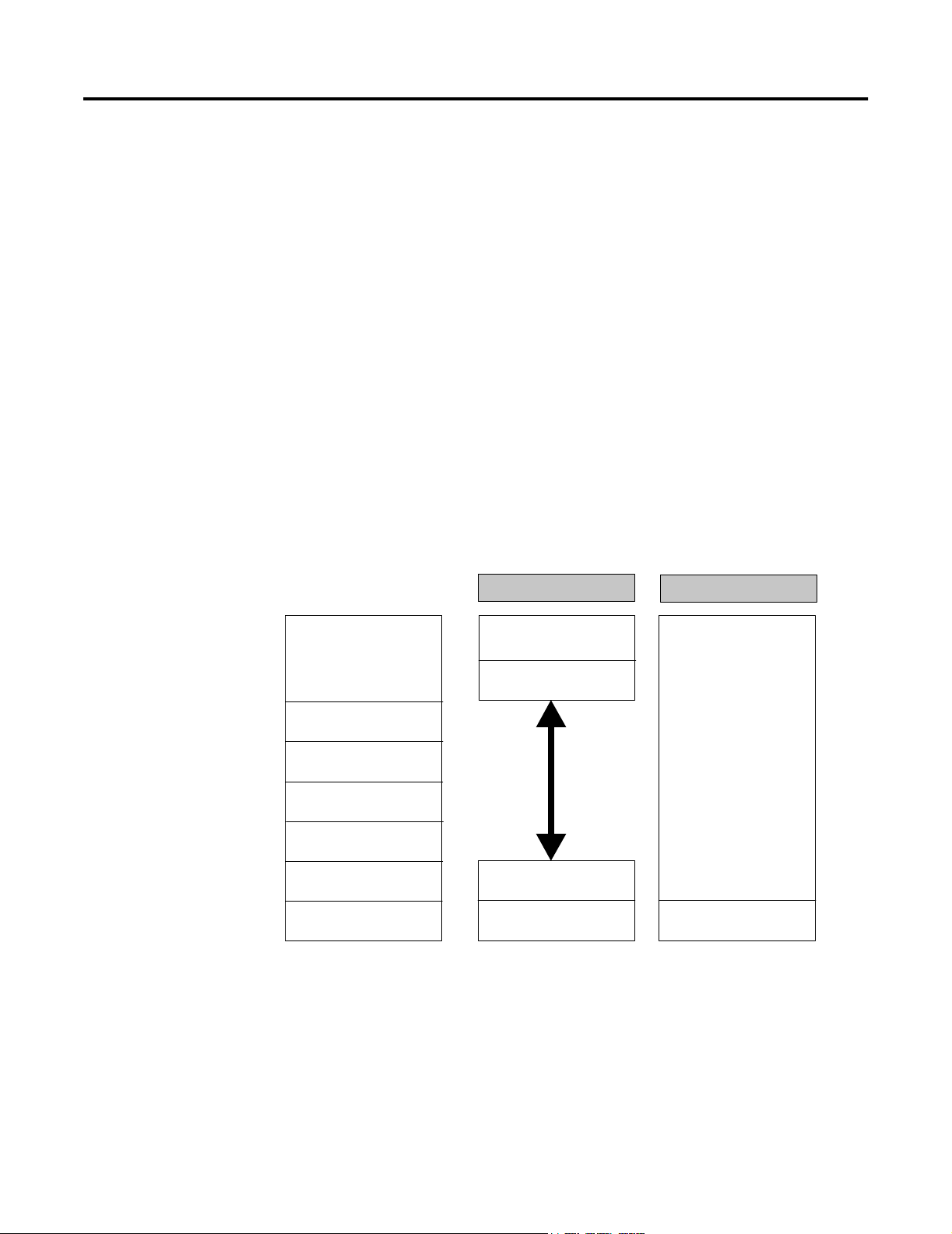
As shown in Figure 1.1, OSI layer 1 is the Physical Layer, OSI layer 2
is the Data Link Layer, and OSI layer 7 is the application layer or the
Fieldbus Message Specification. A Fieldbus Access Sublayer maps the
Fieldbus Message Specification onto the Data Link Layer. Fieldbus
does not use OSI layers 3 to 6, and layers 2 and 7 form the
Communication Stack. Also, the OSI model does not define a User
Application, but the Fieldbus Foundation does.
Figure 1.1 OSI versus Fieldbus communication model
OSI Model
Application Layer
7
Presentation Layer
6
5
4
3
2
1
Session Layer
Transport Layer
Network Layer
Data Link Layer
Physical Layer
Fieldbus Model
User Application
Fieldbus Message
Specification
Fieldbus Access
Sublayer
Data Link Layer
Physical Layer
User Application
Communication
Stack
Physical Layer
Publication 1757-UM006A-EN-P - May 2002
Page 18

1-4 The Fieldbus Communication Model
Communication Layer Description
The following table provides a summarized description of the
communication layers that make up the FOUNDATION Fieldbus. The
Fieldbus Foundation maintains a complete library of detailed
reference specifications including a Technical Overview, and Wiring
and Installation Guides.
Table 1.A Communication Layer Descriptions
Layer Functional Description Associated Terms
Physical Defines the transmission medium for fieldbus signals and the message conversion tasks
to/from the Communication Stack.
Based on the Manchester Biphase-L Encoding technique, so a F
device interprets a positive transition in the middle of a bit time as logical “0” and a
negative transition as logical “1”.
Complies with existing International Electrotechnical Commission (IEC 1158-2) and the
Instrumentation, Systems, and Automation Society (ISA S50.02) physical layer
standards. And, it can be used with existing 4 to 20mA wiring.
Data Link (DLL) Defines how messages are transmitted on a multi-drop network. It uses a deterministic
centralized bus scheduler called a Link Active Scheduler (LAS) to manage access to the
fieldbus. It controls scheduled and unscheduled communications on the fieldbus in a
publish/subscribe environment.
Identifies device types as Basic Device, Link Master, or Bridge. A Link Master device
type can become a Link Active Scheduler (LAS) for the network.
Fieldbus Access
Sublayer (FAS)
Fieldbus
Message
Specification
(FMS)
Defines the types of services used to pass information to the Fieldbus Message
Specification layer. The types of services are defined as Virtual Communication
Relationships (VCR).
The VCR types are Client/Server, Report Distribution, and Publisher/Subscriber. The
Client/Server type handles all operator messages. The Report Distribution type handles
event notification and trend reports. The Publisher/Subscriber type handles the
publishing of User Application function block data on the network.
Defines how fieldbus devices exchange User Application messages across the fieldbus
using a set of standard message formats. It uses object descriptions that are stored in
an object dictionary (OD) to facilitate data communication. The OD also includes
descriptions for standard data types such as floating point, integer, Boolean, and
bitstring.
A Virtual Field Device (VFD) mirrors local device data described in the OD. A physical
device may have more than one VFD.
Provides these communication services to standardize the way the User Applications
such as function blocks communicate over the fieldbus - Context Management, Object
Dictionary, Variable Access, Event, Upload/Download, and Program Invocation.
Uses a formal syntax description language called Abstract Syntax Notation 1 (ASN-1) to
format FMS messages and applies special behavioral rules for certain types of objects.
OUNDATION Fieldbus (FF)
H1, 31.25 kbit/s signal rate
H1 Link
H1 Segment
HSE, High Speed Ethernet
Compel Data (CD) message
Pass Token (PT) message
Time Distribution (TD)
message
Live List
Link Active Scheduler (LAS)
Virtual Communication
Relationship (VCR)
Object Dictionary (OD)
Virtual Field Device (VFD)
Network Management
Information Base (NMIB)
System Management
Information Base (SMIB)
Publication 1757-UM006A-EN-P - May 2002
Page 19
The Fieldbus Communication Model 1-5
Table 1.A Communication Layer Descriptions
Layer Functional Description Associated Terms
User
Application or
Function Block
Application
Process (FBAP)
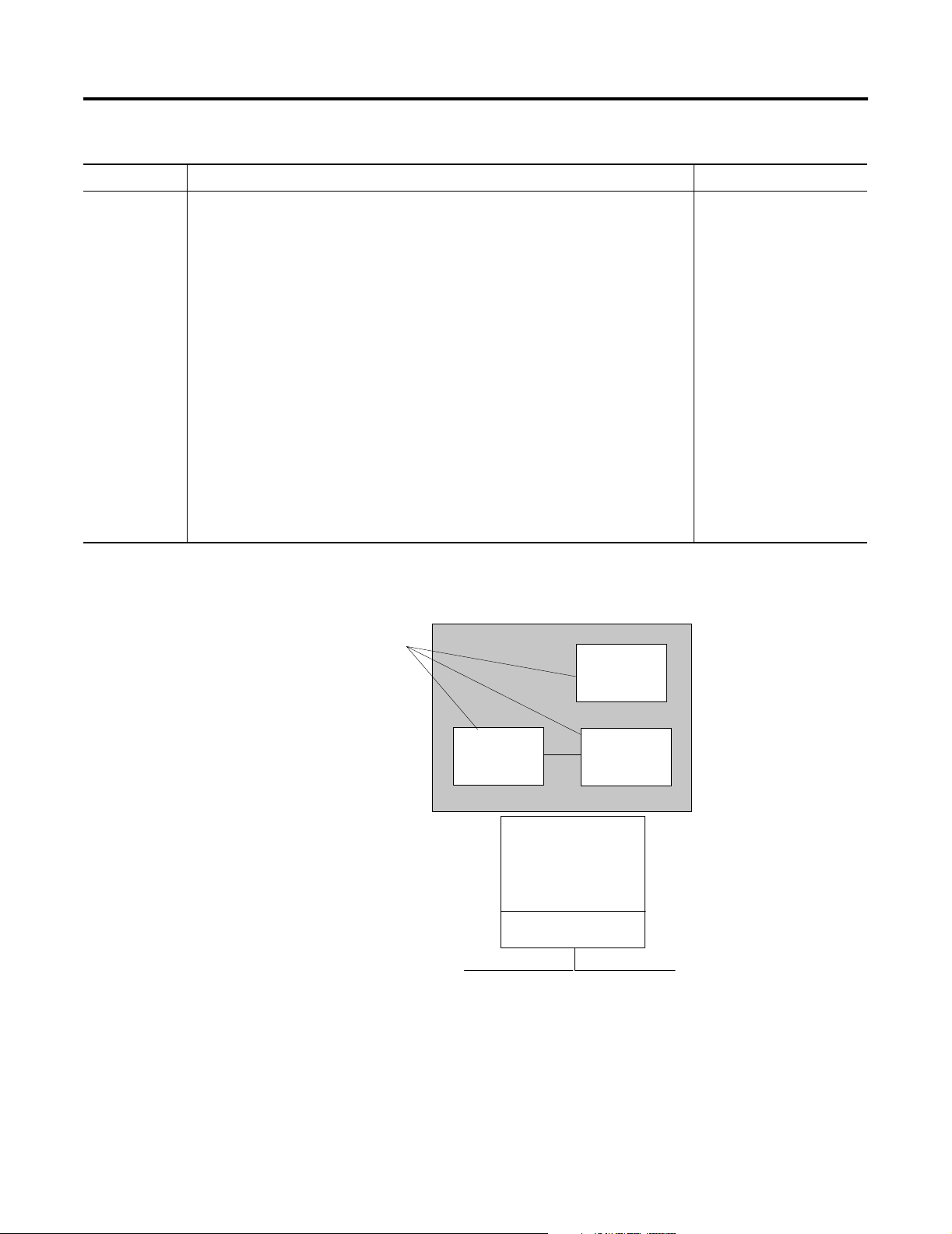
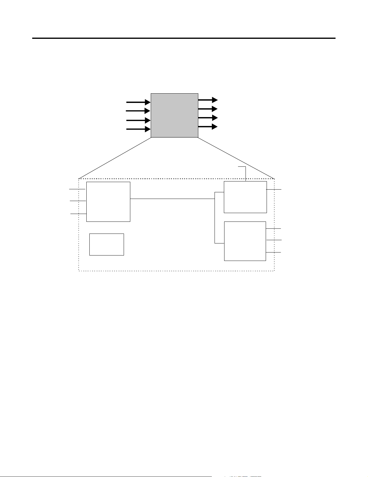
Defines blocks to represent different types of application functions. The three types of
blocks are the Resource block, the Function block, and the Transducer block. See
Figure 1.2.
The Resource block is used to describe characteristics of the fieldbus device such as the
device name, manufacturer, and serial number. Each fieldbus device requires one
Resource block.
The Function block is used to define the specific characteristics of the process control
function. The Fieldbus Foundation provides a set of pre-defined function blocks. A single
fieldbus device can include many Function blocks to achieve the desired control
functionality. See the following section, Standard Function Blocks for more information.
The Transducer block is used to interface Function blocks with local input/output
devices. They read sensors and command outputs, and contain information such as
calibration date and sensor type. One Transducer block is usually included for each input
or output Function block.
These associated objects are also defined in the User Application: Link Objects, Trend
Objects, Alert Objects, and View Objects. They provide linking between internal Function
block inputs and outputs, trending of Function block parameters, reporting of alarms and
events, viewing of predefined block parameter sets through one of four defined views.
The four defined views are View 1 - Operation Dynamic, View 2 - Operation Static, View
3 - All Dynamic, and View 4 - Other Static.
Figure 1.2 Function Block Application Process based on blocks
Fieldbus Foundation
Defined Blocks
User Application
Resource
Block
Resource block
Function block
Transducer block
Link Objects
Trend Objects
Alert Objects
View Objects
View 1 - Operation Dynamic
View 2 - Operation Static
View 3 - All Dynamic
View 4 - Other Static
Transducer
Block
Function
Block
Communication
Stack
Physical Layer
Fieldbus
Publication 1757-UM006A-EN-P - May 2002
Page 20

1-6 The Fieldbus Communication Model
Standard Function Blocks
The key to fieldbus interoperability is the User Application or
Function Block Application Process (FBAP) that defines standard
function blocks that can reside in field devices and be interconnected
as a distributed process control system. A function block is a named
entity that has inputs, outputs, and parameters. It performs certain
functions that operate on its inputs and produce outputs in
accordance with its assigned parameters. The Fieldbus Foundation
Function Blocks are similar in nature to the Function Blocks used to
build control strategies in the Control Builder application in the
ProcessLogix system.
The Fieldbus Foundation provides the standard Function Blocks listed
below for basic control functionality. They also support additional
blocks for more complex applications. Please refer to the applicable
Fieldbus Foundation specification for more information about these
additional blocks.
Table 1.B Function Block Specifications
Function Block Abbreviation Class
Analog Input AI Input
Analog Output AO Output
Bias/Gain BG Control
Control Selector CS Control
Discrete Input DI Input
Discrete Output DO Output
Manual Loader ML Control
Proportional/Derivative PD Control
Proportional/Integral/Deriva
tive
Ratio RA Control
PID Control
Publication 1757-UM006A-EN-P - May 2002
Page 21
The Fieldbus Communication Model 1-7
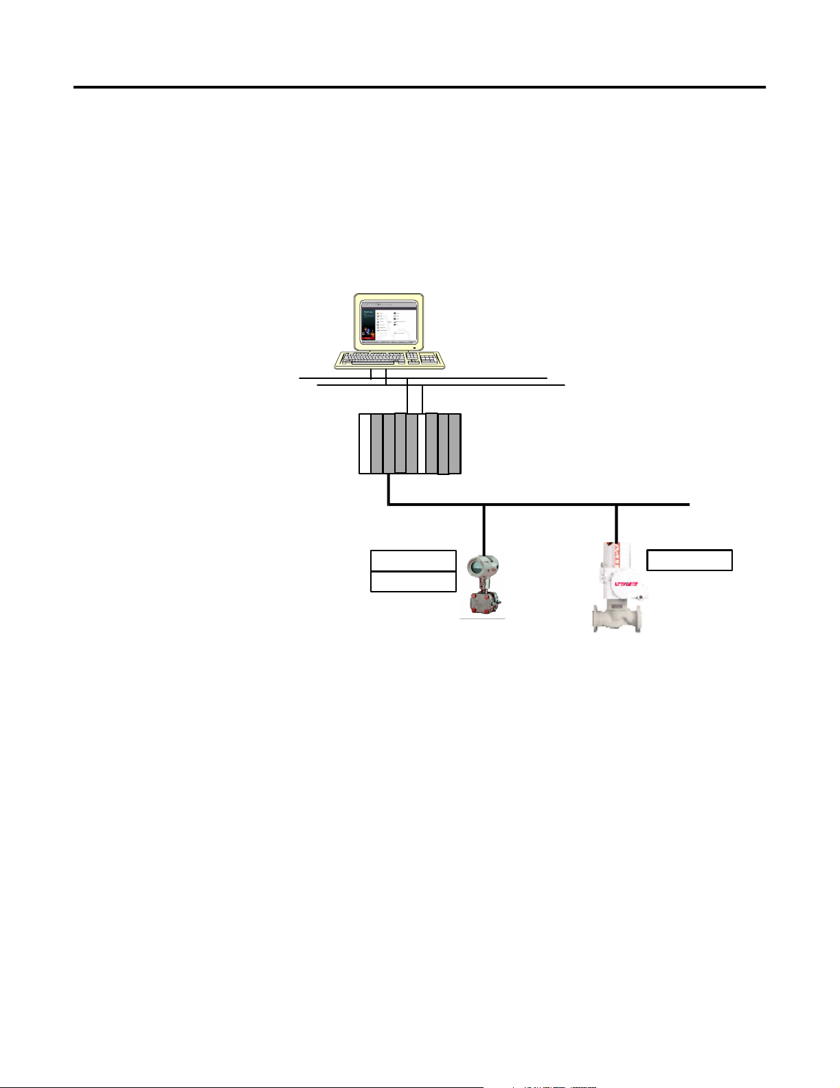
Function blocks make it possible to build a control loop using fieldbus
devices that include the appropriate Function block types. For
example, a pressure transmitter that contains an Analog Input and
Proportional/Integral/Derivative blocks can be used with a valve
containing an Analog Output block to form a control loop, as shown
in Figure 1.3.
Figure 1.3 Using Function Blocks in Fieldbus Devices to Form a Control Loop
AI Block
PID Block
Fieldbus
AO Block
Device 1
Device 2
Publication 1757-UM006A-EN-P - May 2002
Page 22

1-8 The Fieldbus Communication Model
About Modes of Operation
Every Function block includes a mode parameter with configured
permitted modes. This structured parameter is composed of the actual
mode, the target mode, the permitted mode, and the normal mode.
The normal mode is the desired operating mode. The actual mode
reflects the mode used during block execution. The target mode may
be set and monitored through the mode parameter. The permitted
mode defines the allowable target mode settings. The following table
provides a summary of the available modes of operation and their
effect on operation.
Table 1.C Modes of Operation
Mode Abbreviation Operation Effect
Out of Service OOS The block is not being evaluated. The output is maintained at the last value, an assigned failsafe
value -last value or configured failsafe value. Set Point is maintained at last value.
Initialization
Manual
IMan The block output is being set in response to the back-calculation input parameter status. When
status is no path to the final output element, control blocks must initialize to provide for bumpless
transfer, when the condition clears. The Set Point may be maintained or initialized to the Process
Variable parameter value.
Local Override LO Applies to control and output blocks that support a track input parameter. Also, manufacturers may
provide a local lockout switch on the device to enable the Local Override mode. The block output is
being set to track the value of the track input parameter. The algorithm must initialize to avoid a
bump, when the mode switches back to the target mode. The Set Point may be maintained or
initialized to the Process Variable parameter value.
Manual Man The block is not being calculated, although it may be limited. The operator directly sets it through an
interface device. The algorithm must initialize to avoid a bump, when the mode switches. The Set
Point may be maintained, initialized to the Process Variable parameter value, or initialized to the Set
Point value associated with the previous (retained) target mode.
Automatic Auto The block's normal algorithm uses a local Set Point value to determine the primary output. An
operator may set the value of the Set Point through an interface device.
Cascade Cas The block's normal algorithm uses a Set Point value fed through the Cascade input parameter from
another block to determine the primary output value.
Remote
Cascade
Remote-Out ROut The block's output is being set by a Control Application running on an interface device through the
RCas The block's Set Point is being set by a Control Application running on an interface device through
the remote-cascade in parameter. The block's normal algorithm uses this Set Point to determine the
primary output value. The block maintains a remote-cascade out parameter to support initialization
of the control application, when the block mode is not remote-cascade.
remote-output in parameter. The algorithm must initialize to avoid a bump, when the mode
switches. The block maintains a remote-output out parameter to support initialization of the Control
Application, when the block mode is not remote-output. The Set Point may be maintained or
initialized to the Process Variable parameter value.
Publication 1757-UM006A-EN-P - May 2002
Page 23
The Fieldbus Communication Model 1-9
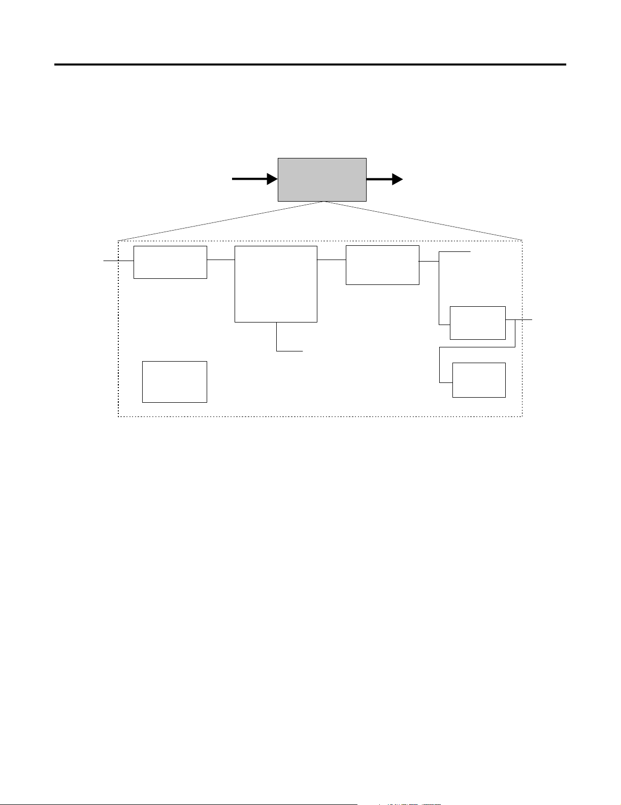
Analog Input Block
Figure 1.4 Functional Schematic for Analog Input Function Block
CHANNEL
Transducer
Simulate
SIMULATE
Mode
SHED_OPT
Convert
L_TYPE
LOW_CUT
XD_SCALE
OUT_SCALE
AI
FIELD_VAL
Filter
PV_FTIME
OUT
PV
Output
Alarms
HI/LO
OUT
Publication 1757-UM006A-EN-P - May 2002
Page 24

1-10 The Fieldbus Communication Model
Table 1.D Analog Input Block Specifications
Description The AI function block takes the input data from a Transducer block and calculates an output to be fed to other fieldbus
function blocks. A functional schematic of the block is shown in Figure 1.4 for reference.
Function Notes • Supports Out of Service (OOS), Manual (Man), and Automatic (Auto) modes.
• The XD_SCALE units code must match the channel units code, or the block will remain in OOS mode after being
configured.
• The OUT_SCALE is normally the same as the transducer, unless the L_TYPE is set to Indirect or Ind Sqr Root, then
the OUT_SCALE determines the conversion from FIELD_VAL to the output.
• If the mode is Auto, the PV is the value the block puts in OUT.
• If the mode is Man, an operator can write a value to OUT.
• The SIMULATE parameter is for testing purposes only and always initializes in the disabled state.
Equation Options FIELD_VAL = 100 x (channel value - EU@0%) / (EU@100% - EU@0%) [XD_SCALE]
Direct: PV = channel value
Indirect : PV = (FIELD_VAL / 100) x (EU@100% - EU@0%) + EU@0% [OUT_SCALE]
Ind Sqr Root: PV = sqrt(FIELD_VAL / 100) x (EU@100% - EU@0%) + EU@0% [OUT_SCALE]
Parameters
(see Appendix A
for definitions of
each parameter)
ACK_OPTION
ALARM_HYS
ALARM_SUM
ALERT_KEY
BLOCK_ALM
BLOCK_ERR
CHANNEL
FIELD_VAL
GRANT_DENY
HI_ALM
HI_HI_ALM
HI_HI_LIM
HI_HI_PRI
HI_LIM
HI_PRI
IO_OPTS
L_TYPE
LO_ALM
LO_LIM
LO_LO_ALM
LO_LO_LIM
LO_LO_PRI
LO_PRI
LOW_CUT
MODE_BLK
OUT
OUT_SCALE
PV
PV_FTIME
SIMULATE
ST_REV
STATUS_OPTS
STRATEGY
TAG_DESC
UPDATE_EVT
XD_SCALE
Publication 1757-UM006A-EN-P - May 2002
Page 25
CAS_IN
RCAS_IN
BKCAL_OUT
RCAS_OUT
The Fieldbus Communication Model 1-11
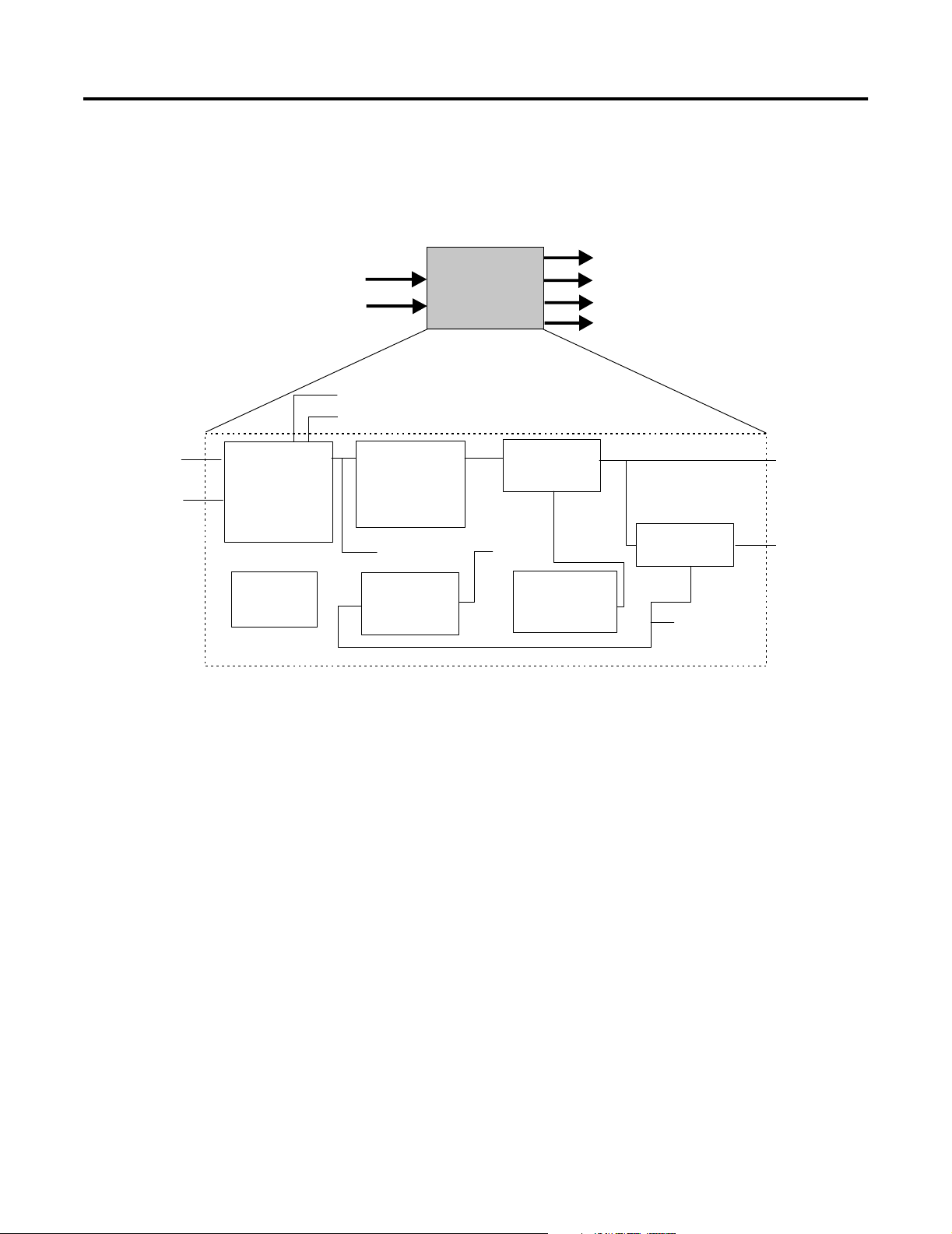
Analog Output Block
Figure 1.5 Functional Schematic for Analog Output Function Block
BKCAL_OUT
AO
OUT
RCAS_OUT
Transducer
CAS_IN
RCAS_IN
Setpoint
SP_RATE_DN
SP_RATE_UP
SP_HI_LIM
SP_LO_LIM
Mode
SHED_OPT
Out Convert
PV_SCALE
XD_SCALE
SP
PV Convert
XD_SCALE
PV_SCALE
Output
PV
Failsafe
FSAFE_TIME
FSAFE_VAL
Simulate
SIMULATE
READBACK
OUT
CHANNEL
Publication 1757-UM006A-EN-P - May 2002
Page 26

1-12 The Fieldbus Communication Model
Table 1.E Analog Output Specifications
Description The Analog Output function block converts the set point (SP) value to a number that can be used by the hardware
associated with the CHANNEL selection. A functional schematic of the block is shown in Figure 1.5 for reference.
Function Notes • Can use either the Set point (SP) value after limiting or the Process Variable (PV) value for the BKCAL_OUT value.
• Supports Out of Service (OOS), Local Override (LO), Manual (Man), Automatic (Auto), Cascade (Cas), and Remote
Cascade (RCas) modes.
• The conversion of Set point (SP) to percent of span is based on the PV_SCALE range.
• The conversion of the percent of span to a compatible value for the hardware is based on the XD_SCALE range.
• Use the Increase to Close Option in IO_OPTS to invert the span.
• Use the Cascade mode to transfer the output of another block to the Set point of the AO block.
• If the hardware, such as a valve positioner, supports a readback value, run this value backwards through the XD
scaling to act as the PV for this block. If this is not supported, READBACK is generated from OUT.
• In the Man mode, an operator can write a value to OUT. A manufacturer must put operational limits in the
Transducer, where an operator cannot access them, to permit the Man mode. If Man mode is not permitted, it must
be supported as a transition mode for exiting the OOS mode
• The SIMULATE parameter is for testing purposes only and always initializes in the disabled state.
Equation Options Temp = (SP - EU@0%) / (EU@100% - EU@0%) [PV_SCALE]
OUT = Temp x (EU@100% - EU@0%) + EU@0% [XD_SCALE]
Temp = (READBACK - EU@0%) / (EU@100% - EU@0%) [XD_SCALE]
PV = Temp x (EU@100% - EU@0%) + EU@0% [PV_SCALE]
Parameters
(see Appendix A
for definitions of
each parameter)
ALERT_KEY
BKCAL_OUT
BLOCK_ALM
BLOCK_ERR
CAS_IN
CHANNEL
FSAFE_TIME
FSAFE_VAL
GRANT_DENY
IO_OPTS
MODE_BLK
OUT
PV
PV_SCALE
RCAS_IN
RCAS_OUT
READBACK
SHED_OPT
SIMULATE
SP
SP_HI_LIM
SP_LO_LIM
SP_RATE_DN
SP_RATE_UP
ST_REV
STATUS_OPTS
STRATEGY
TAG_DESC
UPDATE_EVT
XD_SCALE
Publication 1757-UM006A-EN-P - May 2002
Page 27
IN_1
BKCAL_IN
CAS_IN
RCAS_IN
TRK_IN_C
TRK_VAL
The Fieldbus Communication Model 1-13
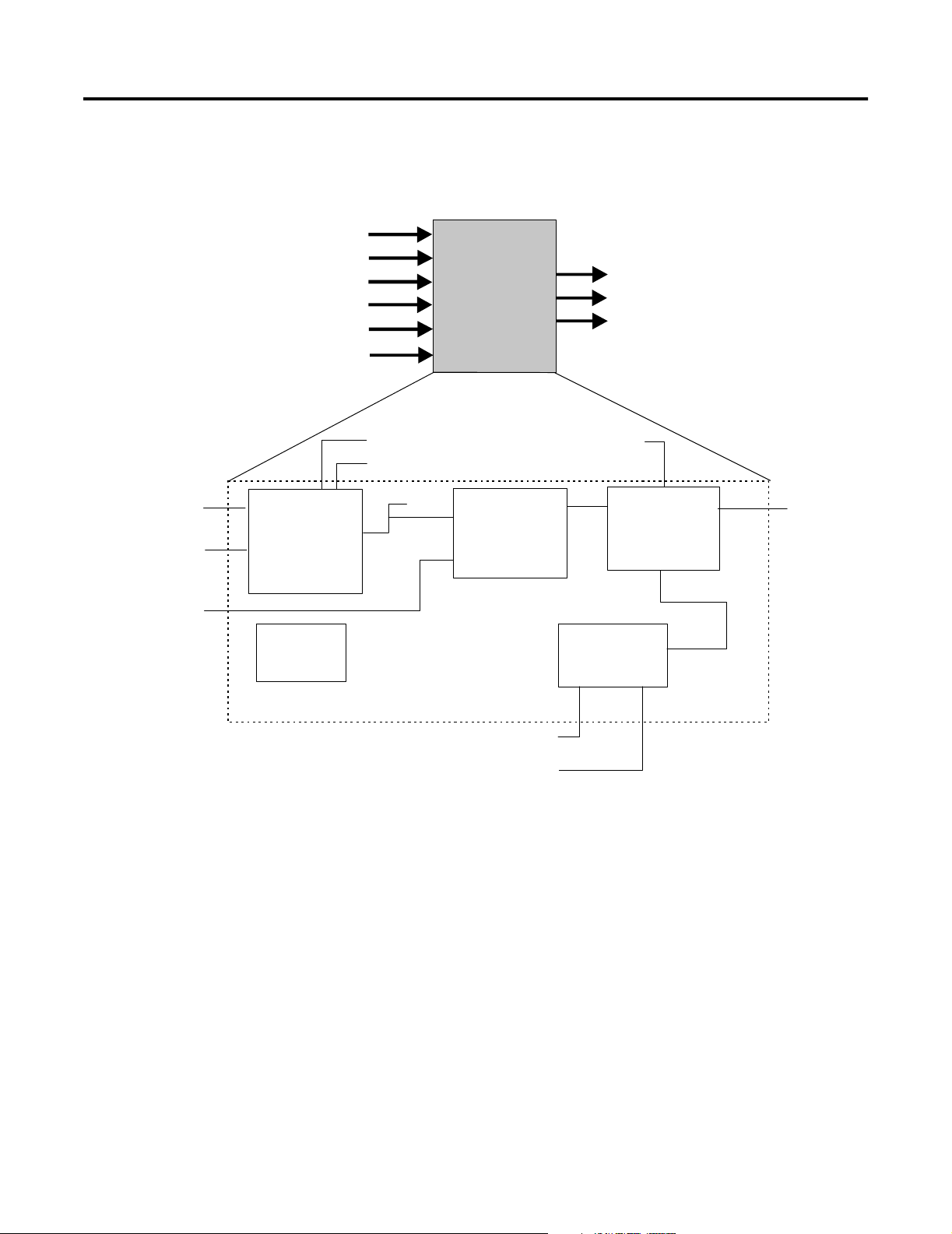
Bias/Gain Block
Figure 1.6 Functional Schematic for Bias/Gain Function Block
BKCAL_OUT
BG
OUT
RCAS_OUT
CAS_IN
RCAS_IN
IN_1
Setpoint
SP_RATE_DN
SP_RATE_UP
SP_HI_LIM
SP_LO_LIM
Mode
SHED_OPT
BKCAL_OUT
RCAS_OUT
SP
Bias & Gain
GAIN
TRK_IN_D
TRK_VAL
BKCAL_IN
Output
OUT_HI_LIM
OUT_LO_LIM
BAL_TIME
Output Track
TRK_SCALE
OUT
Publication 1757-UM006A-EN-P - May 2002
Page 28

1-14 The Fieldbus Communication Model
Table 1.F Bias/Gain Block Specifications
Description The Bias/Gain function block can be used for biased external feedforward control or to set several unit controllers,
such as boiler masters, from one controller output, such as a plant master. A functional schematic of the block is
shown in Figure 1.6 for reference.
Function Notes • Supports Out of Service (OOS), Initialization Manual (IMan) Local Override (LO), Manual (Man), Automatic (Auto),
Cascade (Cas), and Remote Cascade (RCas) modes.
• The output supports the track algorithm.
• The Balance Ramp option is supported.
• The CONTROL_OPTS selection Act on IR determines whether initialization requests are to be passed on or acted
on locally by changing the BIAS value.
• If the Act on IR option is false, a status of Not Invited (NI) or Initialization Request (IR) at BKCAL_IN will be passed
to BKCAL_OUT. The BKCAL_OUT value will be calculated from the value of BKCAL_IN adjusted for SP and GAIN,
as determined by the control or process status of IN_1. When the upstream block sends an Initialization
Acknowledge (IA) status, this block will send IA status, since its output will now be nearly equal to the value of
BKCAL_IN.
• If the Act on IR option is true, a status of NI or IR at BKCAL_IN results in an adjustment to SP to balance OUT to
the value of BKCAL_IN. The IA status can be sent as soon as IR is detected. BKCAL_OUT will not request
initialization.
• The TRK_VAL input brings in an external value or uses a constant. The TRK_SCALE values convert the TRK_VAL to
a percent of output span value. If the CONTROL_OPTS Track Enable selection is true and TRK_IN_D is true, the
converted TRK_VAL replaces the output (OUT), when the block is in Automatic, Cascade, or Remote Cascade
mode. The CONTROL_OPTS Track in Manual selection must be true for this to occur in Manual mode. If the actual
mode is OOS or IMan, the track request is ignored.
• If the TRK_VAL replaces the OUT, its status becomes Locked Out with Limits set to Constant. The actual mode
goes to LO. The status of RCAS_OUT goes to Not Invited (NI), if not already there.
• If the status of TRK_IN_D is Bad, its last usable value will be maintained and acted upon. If the device restarts,
losing the last usable value, it will be set to false.
• If the status of TRK_VAL is Bad, the last usable value will be used. If there is no last usable value, the present
value of the OUT will be used.
Equation Options In Automatic mode: OUT = (IN_1 + SP) x GAIN
If IN_1 has Non-Cascade status: BKCAL_OUT = (BKCAL_IN / GAIN) - IN_1
If IN_1 has Cascade status: BKCAL_OUT = (BKCAL_IN / GAIN) - SP
Parameters
(see Appendix A for
definitions of each
parameter)
ALERT_KEY
BAL_TIME
BKCAL_IN
BKCAL_OUT
BLOCK_ALM
BLOCK_ERR
CAS_IN
CONTROL_OPTS
GAIN
GRANT_DENY
IN_1
MODE_BLK
OUT
OUT_HI_LIM
OUT_LO_LIM
OUT_SCALE
RCAS_IN
RCAS_OUT
SHED_OPT
SP
SP_HI_LIM
SP_LO_LIM
SP_RATE_DN
SP_RATE_UP
ST_REV
STATUS_OPTS
STRATEGY
TAG_DESC
TRK_IN_D
TRK_SCALE
TRK_VAL
UPDATE_EVT
Publication 1757-UM006A-EN-P - May 2002
Page 29
The Fieldbus Communication Model 1-15
Control Selector Block
Figure 1.7 Functional Schematic for Control Selector Function Block
SEL_1
SEL_2
SEL_3
SEL_1
SEL_2
SEL_3
BKCAL_IN
Selection
SEL_TYPE
Mode
CS
OUT
BKCAL_SEL_1
BKCAL_SEL_2
BKCAL_SEL_3
BKCAL_IN
OUT_HI_LIM
OUT_LO_LIM
Back Calc
Output
OUT
BKCAL_SEL_1
BKCAL_SEL_2
BKCAL_SEL_3
Publication 1757-UM006A-EN-P - May 2002
Page 30

1-16 The Fieldbus Communication Model
Table 1.G Control Selector Block Specifications
Description The Control Selector function block accepts input from up to three control signals and selects one for output based on
the SEL_TYPE setting of High, Middle, or Low. A functional schematic of the block is shown in Figure 1.7 for reference.
Function Notes • All inputs must have the same scaling as OUT, since any one can be selected for OUT.
• Supports Out of Service (OOS), Initialization Manual (IMan) Local Override (LO), Manual (Man), and Automatic
(Auto) modes.
• If an input has a sub-status of Do Not Select, it will not be selected.
• Three separate back calculation outputs (BKCAL_SEL_1, 2, 3) are available - one for each input (SEL_1, 2, 3).
• The status will identify those inputs that are not selected. Control signals that are not selected are limited in one
direction only as determined by the SEL_TYPE selection.
• The value of each BKCAL_SEL_1, 2, 3 output is the same as OUT. The limits of back calculation outputs
corresponding to not-selected inputs will be high for a low selection, low for a high selection, or one of each for a
middle selection.
• If the status of an input is Bad, it is not eligible for selection. If the status of an input is Uncertain, it is treated as
Bad unless the STATUS_OPTS selection is Use Uncertain as Good.
• When all inputs are Bad, the actual mode goes to Manual. This condition will set Initiate Failsafe (IFS) in the output
status, if the STATUS_OPTS setting is IFS if BAD IN.
• If SEL_TYPE selection is Middle and only two inputs are good, the higher input will be selected.
• If the status of BKCAL_IN is Not Invited (NI) or Initialization Request (IR), it is passed back on all three back
calculation outputs. This causes all initializable inputs to initialize to the BKCAL_IN value. Otherwise, if the status
of BKCAL_IN is not normal, it is passed back on the BKCAL_SEL_N, where N is the number of the selected input.
The back calculation outputs for not-selected inputs just have the Not Selected status with the appropriate high or
low limit set.
• When the mode is Manual, no input is selected. All three back calculation outputs will have a Not Invited status
and Constant limits, with a value equal to OUT.
Parameters
(see Appendix A
for definitions of
each parameter)
ALERT_KEY
BKCAL_IN
BKCAL_SEL_1
BKCAL_SEL_2
BKCAL_SEL_3
BLOCK_ALM
BLOCK_ERR
GRANT_DENY
MODE_BLK
OUT
OUT_HI_LIM
OUT_LO_LIM
OUT_SCALE
SEL_1
SEL_2
SEL_3
SEL_TYPE
ST_REV
STATUS_OPTS
STRATEGY
TAG_DESC
UPDATE_EVT
Publication 1757-UM006A-EN-P - May 2002
Page 31

The Fieldbus Communication Model 1-17
Discrete Input Block
Figure 1.8 Functional Schematic for Discrete Input Function Block
Transducer
CHANNEL
Table 1.H Discrete Input Block Specifications
Description The Discrete Input function block takes the discrete input data from a selected Transducer block channel and provides
Simulate
SIMULATE_D
Mode
SHED_OPT
it as an output for other fieldbus function blocks. A functional schematic of the block is shown in Figure 1.8 for
reference.
Optional
Invert
FIELD_VAL_D
DI
Filter
PV_FTIME
OUT
PV_D
Output
Alarms
OUT_D
DISC
Function Notes • Supports Out of Service (OOS), Manual (Man), and Automatic (Auto) modes.
• The FIELD_VAL_D represents the true ON/OFF state of the value from the Transducer, using XD_STATE.
• Use the IO_OPTS Invert selection to do a Boolean NOT function between the field value and the output.
• Use the PV_FTIME to set the time that the input must be in one state before it gets passed to the PV_D.
• The PV_D is always the value that the block places in OUT_D, when the mode is Automatic.
• In Manual mode, if allowed, an operator can write a value to OUT_D.
• The SIMULATE_D parameter is for testing purposes only and always initializes in the disabled state.
Parameters
(see Appendix A
for definitions of
each parameter)
ACK_OPTION
ALARM_SUM
ALERT_KEY
BLOCK_ALM
BLOCK_ERR
CHANNEL
DISC_ALM
DISC_LIM
DISC_PRI
FIELD_VAL_D
GRANT_DENY
IO_OPTS
MODE_BLK
OUT_D
OUT_STATE
PV_D
PV_FTIME
SIMULATE_D
ST_REV
STATUS_OPTS
STRATEGY
TAG_DESC
UPDATE_EVT
XD_STATE
Publication 1757-UM006A-EN-P - May 2002
Page 32

1-18 The Fieldbus Communication Model
CAS_IN_D
RCAS_IN_D
Discrete Output Block
Figure 1.9 Functional Schematic for Discrete Output Function Block
BKCAL_OUT_D
DO
BKCAL_OUT_D
RCAS_OUT_D
OUT_D
RCAS_OUT_D
Transducer
CAS_IN_D
RCAS_IN_D
Setpoint
Mode
SHED_OPT
Optional
Invert
SP_D
Optional
Invert
Output
PV_D
Failsafe
FSAFE_TIME
FSAFE_VAL_D
Simulate
SIMULATE_D
READBACK_D
OUT_D
CHANNEL
Table 1.I Discrete Output Block Specifications
Description The Discrete Output function block converts the value in SP_D to something useful for the hardware linked to the
CHANNEL selection. A functional schematic of the block is shown in Figure 1.9 for reference.
Function Notes • Supports Out of Service (OOS), Local Override (LO), Manual (Man), Automatic (Auto), Cascade (Cas), and Remote
Cascade (RCas) modes.
• The Set point (SP_D) supports the full cascade sub-function.
• Use the Cascade mode to transfer the output of another block to the Set point (SP_D) of the DO block.
• Use the IO_OPTS Invert selection to do a Boolean NOT function between the field value and the output.
• Use the IO_OPTS Invert selection to do a Boolean NOT function between the SP_D and the output.
• If the hardware supports a readback value, it is used for READBACK_D, and, after accounting for the IO_OPTS
Invert selection, acts as the PV_D for this block. If this is not supported, READBACK is generated from OUT_D.
• In the Man mode, an operator can force the output, in a programmable logic controller sense. If Man mode is not
permitted, it must be supported as a transition mode for exiting the OOS mode
• The SIMULATE_D parameter is for testing purposes only and always initializes in the disabled state.
Parameters
(see Appendix A
for definitions of
each parameter)
ALERT_KEY
BKCAL_OUT_D
BLOCK_ALM
BLOCK_ERR
CAS_IN_D
CHANNEL
FSAFE_TIME
FSAFE_VAL_D
GRANT_DENY
Publication 1757-UM006A-EN-P - May 2002
IO_OPTS
MODE_BLK
OUT_D
PV_D
PV_STATE
RCAS_IN_D
RCAS_OUT_D
READBACK_D
SHED_OPT
ST_REV
STATUS_OPTS
STRATEGY
TAG_DESC
UPDATE_EVT
XD_STATE
SIMULATE_D
SP_D
Page 33

The Fieldbus Communication Model 1-19
Manual Loader Block
Figure 1.10 Functional Schematic for Manual Loader Function Block
IN
BKCAL_IN
ROUT_IN
TRK_IN_D
TRK_VAL
ML
BKCAL_IN
OUT
ROUT_OUT
IN
Filter
PV_FTIME
Mode
SHED_OPT
PV
Alarm
HI/LO
TRK_IN_D
TRK_VAL
ROUT_IN
Output Track
TRK_SCALE
ROUT_OUT
Output
OUT_HI_LIM
OUT_LO_LIM
OUT
Publication 1757-UM006A-EN-P - May 2002
Page 34

1-20 The Fieldbus Communication Model
Table 1.J Manual Loader Block Specifications
Description The Manual Loader function block output is not set by the block's algorithm. Its output can be set by an operator in the
Manual mode or a program in the Remote-Out mode. A functional schematic of the block is shown in Figure 1.10 for
reference.
Function Notes • Supports Out of Service (OOS), Initialization Manual (IMan), Local Override (LO), Manual (Man), and Remote-Out
(ROut) modes.
• Accepts output from an AI block as its input (IN) to get a PV filtered by PV_FTIME.
• The block's algorithm uses value and status for alarming only.
• If selected, the STATUS_OPTS of IFS if BAD IN will work.
• The BKCAL_IN value and status can force balancing of the output.
• The TRK_VAL input brings in an external value or uses a constant. The TRK_SCALE values convert the TRK_VAL to
a percent of output span value. If the CONTROL_OPTS Track Enable selection is true and TRK_IN_D is true, the
converted TRK_VAL replaces the output (OUT), when the block is in Remote-Out (ROut) mode. The CONTROL_OPTS
Track in Manual selection must be true for this to occur in Manual mode. If the actual mode is OOS or IMan, the
track request is ignored.
• If the TRK_VAL replaces the OUT, its status becomes Locked Out with Limits set to Constant. The actual mode goes
to LO. The status of ROUT_OUT goes to Not Invited (NI), if not already there.
• If the status of TRK_IN_D is Bad, its last usable value will be maintained and acted upon. If the device restarts,
losing the last usable value, it will be set to false.
• If the status of TRK_VAL is Bad, the last usable value will be used. If there is no last usable value, the present value
of the OUT will be used.
Parameters
(see Appendix A
for definitions of
each parameter)
ACK_OPTION
ALARM_HYS
ALARM_SUM
ALERT_KEY
BKCAL_IN
BLOCK_ALM
BLOCK_ERR
CONTROL_OPTS
GRANT_DENY
HI_ALM
HI_HI_ALM
HI_HI_LIM
HI_HI_PRIHI_LIM
HI_PRI
IN
LO_ALM
LO_LIM
LO_LO_ALM
LO_LO_LIM
LO_PRI
LO-LO_PRI
MODE_BLK
OUT
OUT_HI_LIM
OUT_LO_LIM
OUT_SCALE
PV
PV_FTIME
PV_SCALE
ROUT_IN
ROUT_OUT
SHED_OPT
ST_REV
STATUS_OPTS
STRATEGY
TAG_DESC
TRK_IN_D
TRK_SCALE
TRK_VAL
UPDATE_EVT
Publication 1757-UM006A-EN-P - May 2002
Page 35

The Fieldbus Communication Model 1-21
Proportional/Derivative Block
Figure 1.11 Functional Schematic for Proportional/Derivative Function Block
IN
BKCAL_IN
CAS_IN
RCAS_IN
ROUT_IN
TRK_IN_D
TRK_VAL
FF_VAL
PD
BKCAL_OUT
OUT
RCAS_OUT
ROUT_OUT
CAS_IN
RCAS_IN
IN
Setpoint
SP_RATE_DN
SP_RATE_UP
SP_HI_LIM
SP_LO_LIM
SP
Filter
PV_FTIME
Mode
SHED_OPT
BKCAL_OUT
RCAS_OUT
Bypass
BYPASS
Control
GAIN
BIAS
BAL_TIME
RATE
Alarm
HI/LO
DEV
FF_VAL
Feed Forward
FF_SCALE
FF_GAIN
BKCAL_HYS
PV
TRK_IN_D
TRK_VAL
Status
BKCAL_IN
ROUT_IN
Output Track
TRK_ SCALE
Output
OUT_HI_LIM
OUT_LO_LIM
ROUT_OUT
OUT
Table 1.K Proportional/Derivative Block
Description The Proportional/Derivative function block provides classic two-mode control function for processes that handle their
own integration. When the Process Variable deviates from the Set point, the PD function acts upon the error to move
the output in a direction to correct the deviation. PD blocks support cascade applications to compensate for the
difference in process time constants of a primary and secondary process measurement. A functional schematic of the
block is shown in Figure 1.11 for reference
Function Notes • Supports Out of Service (OOS), Initialization Manual (IMan), Local Override (LO), Manual (Man), Automatic (Auto),
Cascade (Cas), Remote Cascade (RCas) and Remote-Out (ROut) modes.
• The input (IN) passes through a filter with a time constant (PV_FTIME). The filtered value becomes the Process
Variable (PV) to be used with the Set point (SP) in the block's algorithm.
• The full cascade SP sub-function is used, with rate and absolute limits. Additional control options are available to
have the SP value track the PV value, when the block's actual mode is IMan, LO, Man, or ROut. Limits do not cause
SP-PV tracking.
• The tuning constant used for the Proportional term is GAIN and RATE is used for the Derivative term. Some
controllers use the inverse values of Proportional Band and repeats per minutes for their tuning constants. Users
can choose which tuning constants they want to display.
Publication 1757-UM006A-EN-P - May 2002
Page 36

1-22 The Fieldbus Communication Model
Table 1.K Proportional/Derivative Block
Function Notes
(cont.)
Parameters
(see Appendix A
for definitions of
each parameter)
• A BYPASS switch function is available for operators to use, when secondary cascade controllers have a bad PV and
the Bypass Enable (LSB) CONTROL_OPTS is ON. The Bypass Enable option is required, since some control schemes
may become unstable when BYPASS is ON. An operator can only set the BYPASS switch, when the block is in the
Man or OOS mode. While BYPASS is ON, the SP value, in percent of range, is passed directly to the target output,
and the value of OUT is used for BKCAL_OUT. When block mode switches to Cascade, the upstream block is
requested to initialize to the value of OUT. Upon transition to bypass OFF, the upstream block is requested to
initialize to the PV value, regardless of the Use PV for BKCAL_OUT CONTROL_OPTS status.
• Use the Balance Ramp CONTROL_OPTS to maintain the BIAS value, when the block is in Manual (Man) mode. An
internal value follows the actual value required to maintain balance. When block mode changes to Automatic
(Auto), the internal value ramps to zero contribution in BAL_TIME seconds. If Balance Ramp option is OFF or not
used, the BIAS value immediately changes to follow the changes to the input or output, when the block is in Man
mode.
• Use the Act on IR CONTROL_OPTS to select whether to ignore initialization requests or act on them by changing
the BIAS. If this option is ON, a status of Not Invited (NI) or Initialization Request (IR) at BKCAL_IN causes the BIAS
term to be adjusted to balance OUT to the value of BKCAL_IN.
• Use the Direct Acting CONTROL_OPTS to define how a change in PV relative to the SP affects the output. When
Direct Acting is ON, the output increases when the PV exceeds the SP. When Direct Acting is OFF, the output
decreases when the PV exceeds the SP. Be sure this option is set correctly and never changed while in the
Automatic mode, since it makes the difference between positive and negative feedback. This option setting also
affects the calculation of the limit states for BKCAL_OUT.
• This block includes a Feed Forward algorithm. It accepts a value that is proportional to some disturbance in the
control loop as its FF_VAL input. The FF_SCALE values convert the FF_VAL to a percent of output span value. The
converted value is multiplied by the FF_GAIN and added to the target output of the block's algorithm. If the status
of FF_VAL is Bad, the last usable value will be used to prevent a bump in the output. When the status returns to
Good, the block adjusts its BIAS term to maintain the previous output.
• The TRK_VAL input brings in an external value or uses a constant. The TRK_SCALE values convert the TRK_VAL to
a percent of output span value. If the CONTROL_OPTS Track Enable selection is true and TRK_IN_D is true, the
converted TRK_VAL replaces the output (OUT), when the block is in Automatic (Auto), Cascade (Cas), Remote
Cascade (RCas), or Remote-Out (ROut) mode. The CONTROL_OPTS Track in Manual selection must be true for this
to occur in Manual mode. If the actual mode is OOS or IMan, the track request is ignored.
• If the TRK_VAL replaces the OUT, its status becomes Locked Out with Limits set to Constant. The actual mode goes
to LO. The status of BKCAL_OUT, RCAS_OUT and ROUT_OUT goes to Not Invited (NI), if not already there.
• If the status of TRK_IN_D is Bad, its last usable value will be maintained and acted upon. If the device restarts,
losing the last usable value, it will be set to false.
• If the status of TRK_VAL is Bad, the last usable value will be used. If there is no last usable value, the present value
of the OUT will be used.
• Use the Obey SP limits if Cas or RCas CONTROL_OPTS to use SP value after limiting in Cas or RCas mode.
• Use the Use PV for BKCAL_OUT CONTROL_OPTS to the PV value for the BKCAL_OUT value.
ACK_OPTION
ALARM_HYS
ALARM_SUM
ALERT_KEY
BAL_TIME
BIAS
BKCAL_HYS
BKCAL_IN
BKCAL_OUT
BLOCK_ALM
BLOCK_ERR
BYPASS
CAS_IN
CONTROL_OPTS
DV_HI_ALM
DV_HI_LIM
DV_HI_PRI
DV_LO_ALM
DV_LO_LIM
DV_LO_PRI
FF_GAIN
FF_SCALE
FF_VAL
GAIN
GRANT_DENY
HI_ALM
HI_HI_ALM
HI_HI_LIM
HI_HI_PRI
HI_LIM
HI_PRI
IN
LO_ALM
LO_LIM
LO_LO_ALM
LO_LO_LIM
LO_LO_PRI
LO_PRI
MODE_BLK
OUT
OUT_HI_LIM
OUT_LO_LIM
OUT_SCALE
PV
PV_FTIME
PV_SCALE
RATE
RCAS_IN
RCAS_OUT
ROUT_IN
ROUT_OUT
SHED_OPT
SP
SP_HI_LIM
SP_LO_LIM
SP_RATE_DN
SP_RATE_UP
ST_REV
STATUS_OPTS
STRATEGY
TAG_DESC
TRK_IN_D
TRK_SCALE
TRK_VAL
UPDATE_EVT
Publication 1757-UM006A-EN-P - May 2002
Page 37

The Fieldbus Communication Model 1-23
Proportional/Integral/Derivative Block
Figure 1.12 Functional Schematic for Porportional/Integral/Derivative Function
Block
IN
BKCAL_IN
CAS_IN
RCAS_IN
ROUT_IN
TRK_IN_D
TRK_VAL
FF_VAL
PID
BKCAL_OUT
OUT
RCAS_OUT
ROUT_OUT
CAS_IN
RCAS_IN
IN
Setpoint
SP_RATE_DN
SP_RATE_UP
SP_HI_LIM
SP_LO_LIM
SP
Filter
PV_FTIME
Mode
SHED_OPT
BKCAL_OUT
RCAS_OUT
Bypass
BYPASS
Control
GAIN
RESET
BAL_TIME
RATE
Alarm
HI/LO
DEV
FF_VAL
Feed Forward
FF_SCALE
FF_GAIN
BKCAL_HYS
PV
TRK_IN_D
TRK_VAL
ROUT_IN
Status
BKCAL_IN
OUT_HI_LIM
OUT_LO_LIM
Output Track
TRK_SCALE
Output
ROUT_OUT
OUT
Table 1.L Proportional/Integral/Derivative Block Specifications
Description The Proportional/Integral/Derivative function block provides classic three-mode control function for closed-loop
control applications. When the Process Variable deviates from the Set point, the PID function acts upon the error to
move the output in a direction to correct the deviation. PID blocks support cascade applications to compensate for the
difference in process time constants of a primary and secondary process measurement. A functional schematic of the
block is shown in Figure 1.12 for reference.
Function Notes • Supports Out of Service (OOS), Initialization Manual (IMan), Local Override (LO), Manual (Man), Automatic (Auto),
Cascade (Cas), Remote Cascade (RCas) and Remote-Out (ROut) modes.
• The input (IN) passes through a filter with a time constant (PV_FTIME). The filtered value becomes the Process
Variable (PV) to be used with the Set point (SP) in the block's algorithm. A PID algorithm will not integrate, if the
limit status of the input (IN) is constant.
• The full cascade SP sub-function is used, with rate and absolute limits. Additional control options are available to
have the SP value track the PV value, when the block's actual mode is IMan, LO, Man, or ROut. Limits do not cause
SP-PV tracking.
Publication 1757-UM006A-EN-P - May 2002
Page 38

1-24 The Fieldbus Communication Model
Table 1.L Proportional/Integral/Derivative Block Specifications
Function Notes
(cont.)
• The tuning constant used for the Proportional term is GAIN, RESET is used for the Integral term, and RATE is used
for the Derivative term. Both RESET and RATE are time constants expressed in seconds. Some controllers use the
inverse values of Proportional Band and repeats per minutes for their tuning constants. Users can choose which
tuning constants they want to display.
• A BYPASS switch function is available for operators to use, when secondary cascade controllers have a bad PV and
the Bypass Enable (LSB) CONTROL_OPTS is ON. The Bypass Enable option is required, since some control schemes
may become unstable when BYPASS is ON. An operator can only set the BYPASS switch, when the block is in the
Man or OOS mode. While BYPASS is ON, the SP value, in percent of range, is passed directly to the target output,
and the value of OUT is used for BKCAL_OUT. When block mode switches to Cascade, the upstream block is
requested to initialize to the value of OUT. Upon transition to bypass OFF, the upstream block is requested to
initialize to the PV value, regardless of the Use PV for BKCAL_OUT CONTROL_OPTS status.
• Use the Direct Acting CONTROL_OPTS to define how a change in PV relative to the SP affects the output. When
Direct Acting is ON, the output increases when the PV exceeds the SP. When Direct Acting is OFF, the output
decreases when the PV exceeds the SP. Be sure this option is set correctly and never changed while in the
Automatic mode, since it makes the difference between positive and negative feedback. This option setting also
affects the calculation of the limit states for BKCAL_OUT.
• This block includes a Feed Forward algorithm. It accepts a value that is proportional to some disturbance in the
control loop as its FF_VAL input. The FF_SCALE values convert the FF_VAL to a percent of output span value. The
converted value is multiplied by the FF_GAIN and added to the target output of the block's algorithm. If the status
of FF_VAL is Bad, the last usable value will be used to prevent a bump in the output. When the status returns to
Good, the block adjusts its Integral (RESET) term to maintain the previous output.
• The TRK_VAL input brings in an external value or uses a constant. The TRK_SCALE values convert the TRK_VAL to
a percent of output span value. If the CONTROL_OPTS Track Enable selection is true and TRK_IN_D is true, the
converted TRK_VAL replaces the output (OUT), when the block is in Automatic (Auto), Cascade (Cas), Remote
Cascade (RCas), or Remote-Out (ROut) mode. The CONTROL_OPTS Track in Manual selection must be true for this
to occur in Manual mode. If the actual mode is OOS or IMan, the track request is ignored.
• If the TRK_VAL replaces the OUT, its status becomes Locked Out with Limits set to Constant. The actual mode goes
to LO. The status of BKCAL_OUT, RCAS_OUT and ROUT_OUT goes to Not Invited (NI), if not already there.
• If the status of TRK_IN_D is Bad, its last usable value will be maintained and acted upon. If the device restarts,
losing the last usable value, it will be set to false.
• If the status of TRK_VAL is Bad, the last usable value will be used. If there is no last usable value, the present value
of the OUT will be used.
• Use the Obey SP limits if Cas or RCas CONTROL_OPTS to use SP value after limiting in Cas or RCas mode.
• Use the Use PV for BKCAL_OUT CONTROL_OPTS to the PV value for the BKCAL_OUT value.
Parameters
(see Appendix A
for definitions of
each parameter)
ACK_OPTION
ALARM_HYS
ALARM_SUM
ALERT_KEY
BAL_TIME
BKCAL_HYS
BKCAL_IN
BKCAL_OUT
BLOCK_ALM
BLOCK_ERR
BYPASS
CAS_IN
CONTROL_OPTS
DV_HI_ALM
DV_HI_LIM
DV_HI_PRI
DV_LO_ALM
Publication 1757-UM006A-EN-P - May 2002
DV_LO_LIM
DV_LO_PRI
FF_GAIN
FF_SCALE
FF_VAL
GAIN
GRANT_DENY
HI_ALM
HI_HI_ALM
HI_HI_LIM
HI_HI_PRI
HI_LIM
HI_PRI
IN
LO_ALM
LO_LIM
LO_LO_ALM
LO_LO_LIM
LO_LO_PRI
LO_PRI
MODE_BLK
OUT
OUT_HI_LIM
OUT_LO_LIM
OUT_SCALE
PV
PV_FTIME
PV_SCALE
RATE
RCAS_IN
RCAS_OUT
RESET
ROUT_IN
ROUT_OUT
SHED_OPT
SP
SP_HI_LIM
SP_LO_LIM
SP_RATE_DN
SP_RATE_UP
ST_REV
STATUS_OPTS
STRATEGY
TAG_DESC
TRK_IN_D
TRK_SCALE
TRK_VAL
UPDATE_EVT
Page 39

Ratio Block
Figure 1.13 Functional schematic for Ratio function block.
IN
IN_1
BKCAL_IN
CAS_IN
RCAS_IN
TRK_IN_D
TRK_VAL
RA
BKCAL_OUT
RCAS_OUT
BKCAL_OUT
OUT
RCAS_OUT
BKCAL_IN
The Fieldbus Communication Model 1-25
CAS_IN
RCAS_IN
IN_1
IN
Setpoint
SP_RATE_DN
SP_RATE_UP
SP_HI_LIM
SP_LO_LIM
Filter
RA_FTIME
Filter
PV_FTIME
Mode
SHED_OPT
SP
Ratio
GAIN
Calc PV
GAIN
Alarm
HI/LO
DEV
PV
Output Track
TRK_SCALE
TRK_IN_D
TRK_VAL
Output
OUT_HI_LIM
OUT_LO_LIM
BAL_TIME
OUT
Table 1.M Ratio Block Specifications
Description The Ratio function block set point is the ratio of its output to its input. A ratio set point of 0.5 produces an output that
is one half of its input. The input (IN_1) is either a wild flow or the output of a blend-pacing controller. The output can
be used as the set point for a secondary flow controller. An input (IN) from the secondary measurement is used to
calculate the actual ratio, which is displayed as the PV. A functional schematic of the block is shown in Figure 1.13 for
reference.
Function Notes • Supports Out of Service (OOS), Initialization Manual (IMan), Local Override (LO), Manual (Man), Automatic (Auto),
Cascade (Cas), and Remote Cascade (RCas) modes.
• The input 1 (IN_1) value to be ratioed passes through a filter with a time constant of RA_FTIME. The filtered value
is multiplied by the Set point (SP) and GAIN to become the target output. The GAIN controls the number of zeros in
the SP display.
• The input (IN) value is the actual value of the ratioed variable and it passes through a filter with a time constant of
PV_FTIME. The filtered IN value is divided by the filtered IN_1 value and the GAIN to become the PV. The units of IN
are not PV, but OUT. The units of IN_1 are OUT units divided by PV units.
Publication 1757-UM006A-EN-P - May 2002
Page 40

1-26 The Fieldbus Communication Model
Table 1.M Ratio Block Specifications
Function Notes
(cont.)
• The full cascade SP sub-function is used, with rate and absolute limits. Additional control options are available to
have the SP value track the PV value, when the block's actual mode is IMan, LO, Man, or ROut. Limits do not cause
SP-PV tracking.
• Use the Act on IR CONTROL_OPTS to select whether to pass initialization requests or act on them locally by
changing the SP value. If this option is OFF or to pass, a status of Not Invited (NI) or Initialization Request (IR) at
BKCAL_IN will be passed to BKCAL_OUT. The BKCAL_OUT value will be calculated from the value of BKCALC_IN
divided by GAIN and IN_1. When the upstream block sends Initialization Acknowledge (IA) status, the block sends
the IA status, since its output will now be nearly identical to the value BKCAL_IN. If this option is ON or to act, a
status of NI or IR at BKCAL_IN adjusts the SP to balance the output to the value of BKCAL_IN. The IA status is sent
as soon as IR is detected. The BKCAL_OUT will not request initialization.
• Use the Balance Ramp CONTROL_OPTS to maintain the ratio SP value, when the block is in Manual (Man) mode.
An internal value follows the actual value required to maintain balance. When block mode changes to Automatic
(Auto), the internal value ramps to zero contribution in BAL_TIME seconds. If Balance Ramp option is OFF or not
used, the ratio SP value immediately changes to follow the changes to the input or output, when the block is in
Man mode.
• The TRK_VAL input brings in an external value or uses a constant. The TRK_SCALE values convert the TRK_VAL to
a percent of output span value. If the CONTROL_OPTS Track Enable selection is true and TRK_IN_D is true, the
converted TRK_VAL replaces the output (OUT), when the block is in Automatic (Auto), Cascade (Cas), or Remote
Cascade (RCas) mode. The CONTROL_OPTS Track in Manual selection must be true for this to occur in Manual
mode. If the actual mode is OOS or IMan, the track request is ignored.
• If the TRK_VAL replaces the OUT, its status becomes Locked Out with Limits set to Constant. The actual mode goes
to LO. The status of BKCAL_OUT, and RCAS_OUT goes to Not Invited (NI), if not already there.
• If the status of TRK_IN_D is Bad, its last usable value will be maintained and acted upon. If the device restarts,
losing the last usable value, it will be set to false.
• If the status of TRK_VAL is Bad, the last usable value will be used. If there is no last usable value, the present value
of the OUT will be used.
• Use the Obey SP limits if Cas or RCas CONTROL_OPTS to use SP value after limiting in Cas or RCas mode.
• Use the “Use PV for BKCAL_OUT” CONTROL_OPTS to the PV value for the BKCAL_OUT value.
Equation Options If Auto mode, OUT = IN_1 (filtered) x SP x GAIN
PV = IN (filtered) / IN_1 (filtered) / GAIN
If IN_1 has non-cascade status, BKCAL_OUT = BKCAL_IN / GAIN / IN_1 (filtered)
If IN_1 has cascade status, BKCAL_OUT = BKCAL_IN / GAIN / SP
Parameters
(see Appendix A
for definitions of
each parameter)
ACK_OPTION
ALARM_HYS
ALARM_SUM
ALERT_KEY
BAL_TIME
BKCAL_IN
BKCAL_OUT
BLOCK_ALM
BLOCK_ERR
CAS_IN
CONTROL_OPTS
DV_HI_ALM
DV_HI_LIM
DV_HI_PRI
DV_LO_ALM
DV_LO_LIM
DV_LO_PRI
GAIN
GRANT_DENY
HI_ALM
HI_HI_ALM
HI_HI_LIM
HI_HI_PRI
HI_LIM
HI_PRI
IN
IN_1
LO_ALM
LO_LIM
LO_LO_ALM
LO_LO_LIM
LO_LO_PRI
LO_PRI
MODE_BLK
OUT
OUT_HI_LIM
OUT_LO_LIM
OUT_SCALE
PV
PV_FTIME
PV_SCALE
RA_FTIME
RCAS_IN
RCAS_OUT
SHED_OPT
SP
SP_HI_LIM
SP_LO_LIM
SP_RATE_DN
SP_RATE_UP
ST_REV
STATUS_OPTS
STRATEGY
TAG_DESC
TRK_IN_D
TRK_SCALE
TRK_VAL
UPDATE_EVT
Publication 1757-UM006A-EN-P - May 2002
Page 41

The Fieldbus Communication Model 1-27
Device Descriptions and Block Parameters
About Device Descriptions
Device Descriptions (DD) are absolutely critical to the interoperability
of fieldbus devices. They define the data needed to establish
communications among different fieldbus devices from multiple
vendors and with control system hosts. The DD provides an extended
description of each object in the User Application Virtual Field Device
(VFD).
The Fieldbus Foundation provides Device Descriptions for all
standard Function Blocks and Transducer Blocks on a CD-ROM.
Manufacturer's provide an “Incremental” DD that references the
standard DDs and describes manufacturer specific features such as
calibration and diagnostic procedures added to their devices.
Device Description Language
The Device Description Language (DDL) is a structured text language
used to write a DDL source file. A DDL source file describes each
device function, parameter, and special feature as well as how a field
device can interact with a host application and other field devices. A
completed DDL source file is converted into a binary formatted DD
output file. The DD output file information can be provided in object
form in the device itself, or on a removable storage media delivered
with the device. A field device's Object Dictionary (OD) can be
transferred from a device to a host using standard Fieldbus Message
Specification services.
Publication 1757-UM006A-EN-P - May 2002
Page 42

1-28 The Fieldbus Communication Model
Level 2:
Function
Block
Parameters
Level 3:
Transducer
Block
Parameters
Device Description infrastructure
The Fieldbus Foundation defines a four-level infrastructure for Device
Descriptions for the sake of consistency. See Figure 1.14 for a
graphical representation of the DD infrastructure.
Figure 1.14 Device Descriptions infrastructure.
Level 1:
Universal
Parameters
Defined by
Fieldbus Foundation
Specification
RESOURCE
TEMP
AI
FLOW
PID
Level 4:
Manufacturer
Specific
Parameters
Defined by
Manufacturer
Resource
Block
Trans ducer
Block
Function
Block
Levels 1, 2, and 3 are the Device Descriptions that the Fieldbus
Foundation provides on CD-ROM.
Level 1 consists of Universal Parameters that define common
attributes such as Tag, Revision, and Mode. All blocks must include
Universal Parameters.
Level 2 consists of Function Block Parameters that define parameters
for all standard Function Blocks including the standard Resource
Block.
Level 3 consists of Transducer Block Parameters that define
parameters for the standard Transducer block. In some cases, the
Transducer Block specification may add parameters to the standard
Resource Block.
Publication 1757-UM006A-EN-P - May 2002
Level 4 is the Manufacturer Specific Parameters that define the
parameters a manufacturer has added to the standard Function Block
and Transducer Block parameters. These added parameters will be
included on the manufacturer's Incremental DD.
Page 43

The Fieldbus Communication Model 1-29
Foundation Fieldbus Performance
Foundation Fieldbus is a powerful network providing both
communication and distributed control capability. However, fast
response is not one of its great capabilities. The screen capture below
reflects the time allocated for 18 function blocks to publish their
outputs on Fieldbus. The average time is about 40 ms. per published
value.
Therefore, in the application reflected in this schedule, you should
plan on a loop closure time of on the order of 1 second if you want
new data from all devices each time you run the loop calculation.
Part of the reason that fieldbus is slow is that Fieldbus devices operate
on very small amounts of current. 10 to 20 ma. per device is typical.
This translates into slow computations in the transmitters. It typically
takes 100 ms for a fieldbus transmitter to make a new measurement of
an input with all the associated calculations completed. Therefore,
when attempting to determine the performance of a fieldbus system,
please recognize these facts.
Performance Calculation Considerations
Some pressure transmitters will read their transducers and create a
new floating point digital readings of the PV every 100 ms. That value
can only be read every 40 to 50 milliseconds because of the Fieldbus
data rate, and of the Fieldbus protocol.
The data rate is 31.25 Kbps, or 31 bits per millisecond. Very very slow
by comparison with ControlNet or Ethernet.
• A minimum Fieldbus message uses 99 bits.
• A minimum response uses 150 bits.
Just to put those messages on the wire takes 8 ms. The protocol says
that you must allow time for each device to send nonscheduled
messages, in addition to the Publishing of the Precess Variables, that
are scheduled. The protocol also says that you must allow significant
time for a Fieldbus device to respond to a request for data or
information. The result of the slow data rate and the protocol dictate
that Fieldbus configuration tools allow 40 to 50 milliseconds for the
transmission of data from each Function Block.
Also, many pressure transmitters measures both the pressure and the
temperature. If the application dictates that both values must be used,
then 80 to 100 milliseconds will be allocated to communicating with
those two function blocks, in that one pressure transmitter. Both the
Pressure and the Temperature interface with other Fieldbus devices
Publication 1757-UM006A-EN-P - May 2002
Page 44

1-30 The Fieldbus Communication Model
through independent function blocks, so each require their own 40 to
50 milliseconds.
The 1788-CN2FF operates on the Fieldbus side at the max. speed of
the Fieldbus, and at the ControlNet rate on the ControlNet side.
Therefore, the 1788-CN2FF is not a limiting factor in a Fieldbus
systems performance. When a 1788-CN2FF operates, the Fieldbus side
and the CN side run asynchronously. When the CN2FF receives data,
it is stored in the CN2FF and is Produced on CN at the NUT rate.
Therefore, in a typical CN2FF Fieldbus system, the controller will be
receiving a lot of redundant data.
In a PLX system, with a FIM fieldbus interface, the Fieldbus side
operates at the Fieldbus data rate, and the controller side operates at
the backplane rate, so again, it is not a restriction on the performance
of a fieldbus system.
Publication 1757-UM006A-EN-P - May 2002
Page 45

Chapter
Integrating Fieldbus into Rockwell
Automation Logix System
2
Overview
Background - the goals of integration
The following table summarizes the major areas of consideration that
were key to defining the goals for bringing Fieldbus into
ProcessLogix.
Table 2.A
Function Goal
Connection of Foundation Fieldbus devices
to a Logix system.
Configuration of Foundation Fieldbus
devices through Tools system.
Integration of Foundation Fieldbus Devices
process, maintenance, and alarm data with
notification and display functions in control
systems.
Integrate fieldbus devices on an H1 link
with Supervisory level ControlNet or
Ethernet network, and/or the I/O ControlNet
network.
Integrate configuration of fieldbus devices
through the NetLinx strategy.
Integrate data from fieldbus devices into
Detail, Group, Trend, Maintenance, and
Alarm displays through the Station
application in ProcessLogix as well as the
Monitoring tab of the Control Builder
application.
1 Publication 1757-UM006A-EN-P - May 2002
Page 46

2-2 Integrating Fieldbus into Rockwell Automation Logix System
Fieldbus Integrated Architecture
As shown in Figure 2.1, Foundation Fieldbus devices can be
connected or integrated into a Rockwell Logix system. ProcessLogix,
Release 400.0 and later can be configured with a Fieldbus Interface
Module (FIM). The FIM serves as the communication gateway
between the Supervisory ControlNet/Ethernet and/or I/O ControlNet
network and the Foundation Fieldbus H1 communications medium. It
works with a Remote Termination Panel (RTP) for connecting and
powering up to two fieldbus H1 links.
For applications that require a more highly distributed connection
and/or communications directly with a PLC5 or ControlLogix 5500
processor, you can us the 1788-CN2FF ControlNet to Foundation
Fieldbus Gateway device.
Figure 2.1 Logix system architecture for Fieldbus integration.
Ethernet (TCP/IP)
Redundant
ProcessLogix
Station
ProcessLogix
Servers
PLC 5
Controller
PLC5/C Controller
Supervisory ControlNet/Ethernet
ProcessLogix and ControlLogix
Data Highway +
1771 Remote I/O
SLC Controller
ControlNet
COMM
STATUS
ControlNET
POWER
A#24
OK
A
B
A
B
Flex Ex
Logix5550
RUN I/O
RS232
OK
BAT
PROGRUN
REM
DH+/RIO
ControlNET
B#15
A#24
OK
CH ACH B
OK
A
B
B
Transmitter
ControlNET
A#24
OK
A
B
A
A
B
ControlNet
Pressure
DEVICENET
1757-FIMRTP
FIM
1788-CN2FF
FOUNDATION
Fieldbus
PLC 5
Controller
PLC5/C Controller
ControlNET
Logix5550
RUN I/O
POWER
RS232
A#24
OK
BAT
OK
A
B
PROGRUN
REM
A
B
Data Highway +
1771 Remote I/O
Redundant Controllers
DH+/RIO
ControlNET
ControlNET
B#15
A#24
A#24
OK
CH ACH B
OK
OK
A
A
B
B
A
A
B
B
SLC Controller
ControlNet
COMM
STATUS
DEVICENET
ControlNET
POWER
A#24
OK
A
B
A
B
I/O ControlNet
ProcessLogix and ControlLogix
DH+/RIO
ControlNET
POWER
A#24
OK
A
B
A
B
ControlNET
ControlNET
Logix5550
RUN I/O
RS232
B#15
A#24
A#24
OK
BAT
OK
CH ACH B
OK
OK
A
A
B
B
PROGRUN
REM
A
A
B
B
ControlNet
Flex Ex
Pressure
Transmitter
DH+/RIO
ControlNET
Logix5550
RUN I/O
RS232
B#15
A#24
OK
BAT
OK
CH ACH B
A
B
PROGRUN
REM
B
DEVICENET
1757-FIMRTP
FIM
1788-CN2FF
FOUNDATION
Fieldbus
43190
ControlNET
DEVICENET
A#24
OK
OK
A
B
A
A
B
Publication 1757-UM006A-EN-P - May 2002
Page 47

Integrating Fieldbus into Rockwell Automation Logix System 2-3
Fieldbus Interface Modules - The Key to an Integrated System
The 1757-FIM, Fieldbus Interface Module is the key to bringing the
Foundation Fieldbus system into a ProcessLogix system. The FIM has
been designed to operate as a stand-alone Foundation Fieldbus
interface or as a bridge between the ProcessLogix control
environment and the fieldbus devices. It supports both the
publish/subscribe and the client/server communication methods to
communicate with fieldbus function blocks. The control connections
must be downstream only.
The FIM is a doublewide module that plugs into a non-redundant
Controller or remote I/O chassis. It connects up to two Fieldbus H1
links through a companion Remote Termination Panel (RTP). These
independent links each have their own link schedule, link master and
time master functions. The RTP is designed for DIN rail mounting
within an enclosure. It optionally accepts a 24 Vdc input from an
external power supply to provide low-level power to fieldbus devices
on the H1 links.
The Fieldbus Interface Module functions as a dual network bridge
using a dynamic data cache to facilitate the exchange of data between
the ControlNet/Ethernet network and the Fieldbus H1 links. It
supports both publish/subscribe and client/server communications
methods to implement control connections between ProcessLogix
function blocks and fieldbus function blocks.
FIM capability includes converting ProcessLogix value-status structure
to fieldbus value-status by mapping similar fields to one another and
defaulting others. This means ProcessLogix can monitor fieldbus
control functions, fully integrate with control functions, or provide a
combination that includes using fieldbus based control as backup for
selected ProcessLogix control functions.
The FIM uses low and high priority send queues to make sure that
publish/subscribe data normally used for control is processed before
less important display access data. Publish/subscribe requests are
placed in the high priority send queue and client/server requests are
placed in the low one.
Publication 1757-UM006A-EN-P - May 2002
Page 48

2-4 Integrating Fieldbus into Rockwell Automation Logix System
Configuration Tools
1788-CN2FF Linking Device
The ControlNet-to-Foundation Fieldbus H1 linking device
(1788-CN2FF) connects a ControlNet™ network with one or two
F
OUNDATION Fieldbus H1 (Fieldbus) networks. Each H1 network
consists of multiple Fieldbus devices. Each field device has one or
more function blocks. Each function block performs an elementary
control function such as analog input, analog output, discrete input, or
discrete output. The ControlNet network consists of controllers, such
as PLC® processors, HMIs, drives, I/O devices, and so on. The linking
device has two broad functions, supporting the following:
• closed-loop control
• configuration and monitoring
ControlBuilder
The ProcessLogix R400.0 Control Builder application supports integral
configuration of fieldbus function blocks with ProcessLogix function
blocks to incorporate fieldbus devices in a unified ProcessLogix
Control Strategy. This means ProcessLogix function blocks and
fieldbus function blocks can be easily interconnected, so control can
reside on the fieldbus link, in the Control Processor/Control Execution
Environment (CEE), or cascaded from CEE to the fieldbus device.
An integrated Fieldbus Library Manager lets users read the
manufacturer's Device Descriptions for fieldbus devices to be tied to
an H1 Link and create individual templates for each fieldbus device
including their function blocks. The fieldbus device templates will
reside in the Engineering Repository Database for ProcessLogix. Once
a fieldbus device template is created, the fieldbus device is easily
associated with the appropriate FIM H1 Link through the Project tab in
Control Builder. The following figure shows how icons are used to
readily identify FIM, H1 Links, and fieldbus devices in the Control
Builder Project tab.
Publication 1757-UM006A-EN-P - May 2002
Page 49

Icon for function block
n
representing FIM
hardware
Icon for function block
representing fieldbus
device to be tied to one
of the H1 Links
Integrating Fieldbus into Rockwell Automation Logix System 2-5
Figure 2.2 Project tab in Control Builder has new icons for Fieldbus components.
Icons for H1 Links
associated with FIM11
1757-FIM
Icons for fieldbus functio
blocks associated with
fieldbus device
Foundation Fieldbus Configuration Tool
To configure the 1788-CN2FF, you use 1788-FFCT Configuration
Software tool. This Fieldbus configuration software uses RSLinx to
connect via ControlNet (supports redundant ControlNet) to any CN2FF
devices on the Network.
Using the FFCT software you can configure any Foundation Fieldbus
device, as well as view, display, and monitor all Foundation Fieldbus
parameters. You can also use this tool to setup the data exchange to
PLCs, ControlLogix, and ProcessLogix processors.
Centralized Operator Interface
The ProcessLogix R400.0 Station application includes Detail Displays
dedicated to the configured FIM, associated H1 Links, fieldbus device,
and associated fieldbus function blocks. They provide access to the
same parameters that are accessible through the control charts and
configuration forms in the Monitoring tab of Control Builder. This
includes manufacturer specific parameters, where applicable.
The reporting of alarm conditions and retrieval of process data for
inclusion in group, trend, history, and schematic displays is closely
integrated with ProcessLogix's existing notification management
system. The existing access authorization levels apply and will take
precedence over fieldbus restrictions specified in Device Descriptions.
Publication 1757-UM006A-EN-P - May 2002
Page 50

2-6 Integrating Fieldbus into Rockwell Automation Logix System
Network Management description
Network Management provides the following capabilities for
managing the communication system of a fieldbus device.
• Loading a Virtual Communication Relationship (VCR) list or
single entries in this list; (A VCR represents a communication
channel through the complete communication stack.)
• Configuring the communication stack;
• Loading the Link Active Schedule (LAS);
• Monitoring performance; and
• Monitoring fault detection.
The collection of managed variables is called the Network
Management Information Base (NMIB).
System Management Description
System Management provides the following functions to coordinate
the operation of various devices in a distributed fieldbus system.
• Assigning node addresses for devices;
• Synchronizing the application clock;
• Distributing application scheduling across the link; and
• Providing support for locating application tags.
It provides the needed facilities for bringing new devices on the link
to an operational state and for controlling the overall system
operation. Information, which is used to control system management
operation, is organized as objects stored in the System Management
Information Base (SMIB).
Publication 1757-UM006A-EN-P - May 2002
Page 51

Integrating Fieldbus into Rockwell Automation Logix System 2-7
About the Device Object
The device object represents a physical device entity connected to the
fieldbus link. It provides access to the device's Network Management
(NM) and System Management (SM) parameters. The client/server
VCR is configured in the FIM to access the Management Interface Base
(MIB) of the device as soon as it joins the network. The Control
Builder does not configure the MIB VCR explicitly. Once the MIB VCR
is configured and opened, FIM retrieves MIB information,
SMdirectory, and NM directory. Knowledge of these directories allows
FIM to transform writes into domain object variables into proper
sequence of domain download operations. The SM directory is also
used to determine the number of application VFDs. The NM directory
is key in attempting to configure VCRs to access Function Block
Application Process VFDs in the device.
About the VFD Object
The Virtual Field Device object represents an application VFD and
provides parameter access to that VFD. Each physical device may
have one or more application VFDs. The FIM attempts to build a
client/server VCR to every VFD in the device, when it is added to the
network. If the VCR configuration is successful, the FIM obtains VFD
and resource identification from the device's VFD. During device
download, you can overwrite VCR configuration used to access VFD
parameters through the Control Builder application.
Fieldbus Device Analog Input Integration
A user can functionally wire the output from an Analog Input (AI)
function block in a fieldbus device residing on an H1 link to the input
of a regulatory control type function block contained in a Control
Module in the ProcessLogix Control Builder application. The
Proportional, Integral, Derivative (PID) function block is a typical
regulatory control type function block.
The Fieldbus Library Manager (FLM) in ProcessLogix R400.0 Control
Builder makes this possible. The FLM reads the manufacturer's DD for
the fieldbus device and creates a device template that is included in
the Project tab of Control Builder. The device template includes the
device's fieldbus function blocks, so it can be configured and
integrated with control strategies through Control Builder.
Publication 1757-UM006A-EN-P - May 2002
Page 52

2-8 Integrating Fieldbus into Rockwell Automation Logix System
Figure 2.3 shows a simplified functional diagram of how the output
from an Analog Input function block in a fieldbus compliant
transmitter is integrated with a PID function block in a Control Module
that is assigned and loaded to the CEE in the Control Processor
Module (CPM).
Figure 2.3 Integration of fieldbus device analog input signal with ProcessLogix
control strategy
CM
CPM/CEE
FIM
Fieldbus
Device
Transducer
PV
Analog
Input
PID
OUT
OP
OP
AOC
FIM
AOC = Analog Output Channel
CEE = Control Execution Environment
CM = Control Module
CPM = Control Processor Module
FIM = Fieldbus Interface Module
OP = Output
PID = Proportional, Integral, Derivative
PV = Process Variable
Publication 1757-UM006A-EN-P - May 2002
Fieldbus Analog Input data manipulation
When the OUT from the fieldbus analog input function block is wired
to the PV input for a PID function block, the Control Builder creates a
CEE input agent to handle the analog input from the fieldbus block.
The block-like input agent maps the data structure (DS-65) of the
OUT parameter to the ProcessLogix PV with status parameter. It
interprets the value portion in fieldbus terms and converts it to
ProcessLogix representation. The floating-point representation is
identical, in most cases, but the fieldbus +/-infinity value must be
converted to a ProcessLogix representation.
If the fieldbus status byte indicates “BAD”, the value must be
converted to Not a Number (NaN) for ProcessLogix representation.
Page 53

Integrating Fieldbus into Rockwell Automation Logix System 2-9
The fieldbus data quality of good, bad, and uncertain is mapped to
the appropriate ProcessLogix parameter of PVSTS, PVSTSFL.NORM,
PRSTSFL.BAD, or PVSTSFL.UNCER.
The fieldbus limit indications of no-limit, limited-low, limited-high,
and constant are mapped to the same four indications for
ProcessLogix. The fieldbus data substatus indicator maps only the
limited number of substatus conditions that have corresponding
ProcessLogix indications.
The handshaking provided by the substatus associated with Good
[cascade] status is not supported from an upstream Fieldbus device.
This means that control may not originate in the field and cascade
into the ProcessLogix Controller.
Fieldbus device Analog Output or PID integration
A user can functionally “wire” the output from a regulatory control
type function block contained in a Control Module in the
ProcessLogix Control Builder application to the input of an Analog
Output (AO) or Proportional, Integral, Derivative (PID) function block
in a fieldbus device residing on an H1 link. The Proportional, Integral,
Derivative (PID) function block is a typical ProcessLogix regulatory
control type function block. The Fieldbus Library Manager (FLM)
included in the R400 Control Builder makes this possible. The FLM
reads the manufacturer's DD for the fieldbus device and creates a
device template that is included in the Project tab of Control Builder.
The device template includes the device's fieldbus function blocks, so
it can be configured and integrated with control strategies through
Control Builder.
Publication 1757-UM006A-EN-P - May 2002
Page 54

2-10 Integrating Fieldbus into Rockwell Automation Logix System
Figure 2.4 shows a simplified functional diagram of how the output
from a PID function block in a Control Module that is assigned and
loaded to the CEE in the Control Processor Module (CPM) is
integrated with an Analog Output function block in a fieldbus
compliant device.
Figure 2.4 Integration of a Fieldbus device analog output signal with ProcessLogix
control strategy
CPM/CEE
CM
AIC
DACQ
PV
PV
P1
PV
PID
BACKCALIN
OP
FIM
Fieldbus
Device
CAS_IN
RCAS_IN
FIM
Analog
Output
RCAS_IN
BKCAL_OUT
RCAS_OUT
OUT
Transd ucer
CAS_IN
AIC = Analog Input Channel
BACKCALIN = Back Calculation Input
BKCAL_OUT = Back Calcul ation Output
CAS_IN = Cascade Input
CEE = Control Execution Environment
CM = Control Module
CPM = Control Processor Module
DACQ = Data Acquistion
FIM = Fieldbus Interface Module
OP = Output
PID = Proportional, Integral, Derivative
PV = Process Variable
RCAS_IN = Remote Cascade Input
RCAS_OUT = Remo te Cascade Output
Publication 1757-UM006A-EN-P - May 2002
Page 55

Integrating Fieldbus into Rockwell Automation Logix System 2-11
Figure 2.5 shows a simplified functional diagram of how the output
from a PID function block in a Control Module that is assigned and
loaded to the CEE in the Control Processor Module (CPM) is
integrated with a cascaded Proportional, Integral, Derivative function
block in a fieldbus compliant device.
Figure 2.5 Integration of fieldbus device PID control with ProcessLogix control
strategy
CM
CPM/CEE
FIM
Fieldbus
Device
Transd ucer
Analog
Input
OUT
CAS_IN
RCAS_IN
ROUT_IN
BKCAL_ IN
TRK_I N_D
TRK_VAL
FF_VAL
IN
AIC
DACQ
PV
PID
PV
P1
FIM
PV
RCAS_IN
BKCAL_OUT
RCAS_OUT
OUT
ROUT_OUT
PID
OP
CAS_IN
RCAS_IN
BACKCALIN
CAS_IN
Analog
Output
BKCAL_OUT
RCAS_OUT
OUT
Transd ucer
AIC = Analog Input Channel
BACKCALIN = Back Calculation Input
BKCAL_IN = Back Calculation Input
BKCAL_OUT = Back Calculation Output
CAS_IN = Cascade Input
CEE = Control Execution Environment
CM = Control Module
CPM = Control Processor Module
DACQ = Data Acquistion
FIM = Fieldbus Interface Module
OP = Output
PID = Proportional, Integral, Derivative
PV = Process Variable
RCAS_IN = Remote Cascad e Input
RCAS_OUT = Remote Cascade Output
ROUT_OUT = Remo te Out Output
Fieldbus Analog Output or PID data manipulation
When the OP from the PID function block is wired to the CAS_IN
input for a fieldbus Analog Output or Proportional, Integral,
Derivative function block, the Control Builder automatically creates a
CEE output agent to handle the analog output to the fieldbus block.
Publication 1757-UM006A-EN-P - May 2002
Page 56

2-12 Integrating Fieldbus into Rockwell Automation Logix System
The block-like output agent maps the ProcessLogix OP with status
parameter to the fieldbus data structure (DS-65) of the CAS_IN
parameter. It interprets the value portion in ProcessLogix terms and
converts it to fieldbus representation. The floating-point
representation is identical, in most cases, but the ProcessLogix
+/-infinity value must be converted to a fieldbus representation. If the
status of OP is “BAD”, its value must be converted from NaN to zero
(0.0) for fieldbus representation or it may retain its previous good
value, as long as the fieldbus status byte indicates “BAD”.
The CEE output agent also accepts a single BKCAL_OUT parameter
with the fieldbus data structure (DS-65) and maps it to the
BACKCALIN parameter of the PID block in ProcessLogix terms.
ATTENTION
The ProcessLogix Control Builder application
automatically makes the appropriate back calculation
connections during configuration and the
connections are “hidden” in Control Chart views.
!
Like the FIM, the output agent supports both publish/subscribe and
client/server communication methods. The publish/subscribe method
allows the FIM to appear as a fieldbus device on the H1 link. The FIM
publishes the output (OP) for subscribing fieldbus device resident
blocks such as Analog Output and Proportional, Integral, Derivative
(PID) through their CAS_IN parameter input connection. This
connection is generally used when the downstream control block is in
the Cas (cascade) mode. This means that the fieldbus block's
BKCAL_OUT parameter is published by the downstream block and
subscribed to by the FIM.
The client/server method allows the FIM to appear as a computing
device on the H1 link. The FIM writes the output (OP) to be read by
fieldbus device resident blocks such as Analog Output and
Proportional, Integral, Derivative (PID) through their RCAS_IN
parameter input connection. This connection is generally used when
the downstream control block is in the RCas (Remote Cascade) mode.
This means that the fieldbus block's BKCAL_OUT parameter is written
by the downstream block and read by the FIM.
Publication 1757-UM006A-EN-P - May 2002
The client/server method also allows the FIM to function in a Direct
Digital Control (DDC) mode or the Remote Out mode in fieldbus
terms. In this case, the FIM writes the output to be read by the
fieldbus PID block though its ROUT_IN parameter input connection.
In turn, the PID block publishes the ROUT_OUT or back calculation
output value for the subscribing FIM.
Page 57

Integrating Fieldbus into Rockwell Automation Logix System 2-13
The ProcessLogix data quality is converted to fieldbus data quality.
The ProcessLogix Good indication is represented as fieldbus
Good(Cascade).
The ProcessLogix limit indications of no-limit, limited-low,
limited-high, and constant are mapped to the same four indications for
fieldbus.
The ProcessLogix control initialization indicators map only to the
limited number of substatus conditions that have corresponding
indications in fieldbus Good(Cascade).
Fieldbus device Discrete Input integration
A user can functionally “wire” the output from a Discrete Input (DI)
function block in a fieldbus device residing on an H1 link to the input
of a Device Control (DEVCTL) function block or other block with a
digital input contained in a Control Module in the ProcessLogix
Control Builder application. The Fieldbus Library Manager (FLM) in
ProcessLogix R400.0 Control Builder makes this possible. The FLM
reads the manufacturer's DD for the fieldbus device and creates a
device template that is included in the Project tab of Control Builder.
The device template includes the device's fieldbus function blocks, so
it can be configured and integrated with control strategies through
Control Builder.
Figure 2.6 shows a simplified functional diagram of how the output
from an Discrete Input function block in a fieldbus compliant
transmitter is integrated with a Device Control (DEVCTL) function
block in a Control Module that is assigned and loaded to the CEE in
the Control Processor Module (CPM).
Publication 1757-UM006A-EN-P - May 2002
Page 58

2-14 Integrating Fieldbus into Rockwell Automation Logix System
Figure 2.6 Integration of fieldbus device digital input signal with ProcessLogix
control strategy
CM
DI[1]
Device
Control
CPM/CEE
FIM
DO[1]
SO
DOC
FIM
Fieldbus
Device
Transducer
Digital
Input
OUT
CEE = Control Execution Environment
CM = Control Module
CPM = Control Processor Module
FIM = Fieldbus Interface Module
DOC = Digital Output Channel
Fieldbus Discrete Input data manipulation
Publication 1757-UM006A-EN-P - May 2002
When the OUT from the fieldbus Discrete Input function block is
wired to the DI[n] input for a DEVCTL function block, the Control
Builder creates a CEE discrete input agent to handle the digital input
from the fieldbus block. The block-like discrete input agent maps the
data structure (DS-66) of the OUT parameter to the ProcessLogix DI[n]
with status parameter. It interprets the value portion in fieldbus terms
as a Boolean for Discrete Input (DI) block and as the appropriate
multi-state representation for special fieldbus Device Control (DC)
block. The value is converted and represented in ProcessLogix at the
output.
The discrete input agent accepts inputs from either a published
parameter or a client/server read parameter, depending upon the
communication method used.
The fieldbus data quality of good(cascade), good(non-cascade), bad,
and uncertain is mapped to the appropriate ProcessLogix parameter
for good, bad, and uncertain.
Page 59

Integrating Fieldbus into Rockwell Automation Logix System 2-15
Fieldbus device Discrete Output data integration
A user can functionally “wire” the output from a discrete process or
control value producing ProcessLogix function block like Device
Control to the input of a Discrete Output block in a fieldbus device
residing on an H1 link. The Fieldbus Library Manager (FLM) included
in the R400 Control Builder makes this possible. The FLM reads the
manufacturer's DD for the fieldbus device and creates a device
template that is included in the Project tab of Control Builder. The
device template includes the device's fieldbus function blocks, so it
can be configured and integrated with control strategies through
Control Builder.
Figure 2.7 shows a simplified functional diagram of how the output
from a Device Control (DEVCTL) function block in a Control Module
that is assigned and loaded to the CEE in the Control Processor
Module (CPM) is integrated with a Discrete Output function block in a
fieldbus compliant device.
Figure 2.7 Integration of fieldbus device digital output signal with ProcessLogix
control strategy
CM
DIC
BACKCALIN
CPM/CEE
FIM
PVFL
FIM
DI[1]
RCAS_IN
Device
Control
DO[1]
CAS_IN
Fieldbus
Device
CAS_IN_D
RCAS_IN_D
Digital
Output
BKCAL_OUT_D
RCAS_OUT_D
OUT_D
Trans duc er
BACKCALIN = Back Calculation Input
BKCAL_OUT_ D = Back Calculat ion Output Discrete
CAS_IN_D = Cascade Input Discrete
CEE = Control Execution Environment
CM = Control Module
CPM = Control Processor Module
DIC = Digital Input Channel
FIM = Fieldbus Interface Module
OP = Output
PVFL = Proc ess Variable Flag
RCAS_IN_D = Remote Cascade Input Discrete
RCAS_OUT_D = Remote Cascade Output Discre te
Publication 1757-UM006A-EN-P - May 2002
Page 60

2-16 Integrating Fieldbus into Rockwell Automation Logix System
Fieldbus Discrete Output data manipulation
When the DO[n] from the Device Control (DEVCTL) function block is
wired to the CAS_IN_D input for a fieldbus Discrete Output function
block, the Control Builder automatically creates a CEE output agent to
handle the discrete output to the fieldbus block. The block-like output
agent maps the ProcessLogix DO[n] with status parameter to the
fieldbus data structure (DS-66) of the CAS_IN_D parameter. It
interprets the value portion in ProcessLogix terms and converts it to
fieldbus representation.
The CEE output agent also accepts a single BKCAL_OUT_D parameter
with the fieldbus data structure (DS-66) and maps it to the
BACKCALIN parameter of the DEVCTL block in ProcessLogix terms.
It sends the outgoing “control signal” either to a subscribed parameter
or a client/server written parameter through the CAS_IN_D or
RCAS_OUT_D connection. It can optionally receive the
backcalculation signal from either the corresponding published
parameter or client/server read parameter.
The ProcessLogix data quality is converted to fieldbus data quality.
The ProcessLogix Good indication is represented as fieldbus
Good(Cascade).
The ProcessLogix control initialization indicators map only to the
limited number of substatus conditions that have corresponding
indications in fieldbus Good(Cascade).
Interface Connections Summary
Since the downstream action with the upstream feedback is the same
for all fieldbus blocks, there are essentially the following six types of
interface connections through the FIM.
• Analog process value into the FIM.
• Discrete process value into the FIM.
• Analog process output from the FIM.
• Discrete process output from the FIM.
Publication 1757-UM006A-EN-P - May 2002
• Analog process output from the FIM with backcalculation
feedback.
Page 61

Integrating Fieldbus into Rockwell Automation Logix System 2-17
• Discrete process output from the FIM with backcalculation
feedback.
Bit types 5 and 6 described in Table 2.B support publish/subscribe
communications in Cascade mode or client/server communications in
Remote Cascade mode. And, the analog values can also be used in the
Remote Out mode.
Fieldbus also supports direct device-to-device (peer-to-peer)
publish/subscribe connections independent of the FIM. The FIM can
also monitor (subscribe to) the data published between the functions
blocks of these fieldbus devices.
Fieldbus status data details
According to Foundation Fieldbus specifications, every fieldbus
function block input and output connection must support a status byte
that provides the following status indications.
• Data Quality (usability)
• Bad Data Cause
• Degraded Data Cause
• Limit Conditions
• Cascade Control Initialization, Rejection
• Fault-State Initiation, Indication
• Local Override Indication
• Worst Case Alarm Indication
• Upstream Block Class Identification
Publication 1757-UM006A-EN-P - May 2002
Page 62

2-18 Integrating Fieldbus into Rockwell Automation Logix System
The status byte structure consists of a 2-bit quality, most significant bit,
field; a 4-bit substatus field; and a 2-bit limits, least significant bit,
field. The following table provides a breakdown of bit assignments for
general reference. The value of the quality field determines the
applicable substatus field indication.
Table 2.B Breakdoun of bit assignments
Bit Quality Substatus, if Quality field is Limits
BAD UNCERTAIN GOOD
(Non-Cascade)
GOOD (Cascade)
(1)
0 BAD Data Quality Non-Specific Non-Specific Non-Specific Non-Specific No Limits
(1)
1UNCERTAIN Data
Quality
2 GOOD
(Non-Cascade)
Configuration Error Last Usable Value Active Block Alarm Initialization
Acknow-ledge (IA)
Not Connected Substitute Active Advisory
Alarm
Initialization Request
(IR)
Low Limit
High Limit
Data Quality
3 GOOD (Cascade)
Data Quality
4 Sensor Failure Sensor Conversion
5 No Communication, with
6 No Communication, with
Device Failure Initial Value Active Critical
Alarm
Unacknow-ledged
Last Usable Value
Not Accurate
Engineering Unit
Range Violation
Block Alarm
Unacknow-ledged
Advisory Alarm
Sub-Normal Unacknow-leged
no Last Usable Value
Critical Alarm
Not Invited (NI) Constant
Not Selected (NS)
Do Not Select (DNS)
Local Override (LO)
7 Out-Of-Service Fault-State Active (FSA)
8 Initiate Fault-State (IFS)
(1)
The Good (non-cascade) substatus is used by output connections for fieldbus blocks such as Analog Input and Discrete Input. The Good (cascade) substatus is used by
output connections for fieldbus blocks such as PID. Both of these substatuses are converted to the single ProcessLogix data quality of Good.
Fieldbus Status Indications
Publication 1757-UM006A-EN-P - May 2002
See Appendix B for list of possible display indications associated with
a given fieldbus status.
Page 63

Integrating Fieldbus into Rockwell Automation Logix System 2-19
Control Mode Interaction
Fieldbus Block Modes Versus Processlogix Modes
Every fieldbus function block including Resource and Transducer
blocks contain the MODE_BLK parameter. This structured parameter
consists of the Actual, Target, Permitted, and Normal modes. Refer
to About Modes of Operation on page 1-8 for descriptions of the eight
modes.
For use within ProcessLogix, the structure of the MODE_BLK
parameter is expanded to add MODE to the existing Actual, Target,
Permitted, and Normal modes as outlined in Table 2.C.
Table 2.C Mode Descriptions
ProcessLogix Mode
Structure
MODE Enumeration Write Only
MODE.TARGET Enumeration Read/Write
Data Type Description FIM Action
ProcessLogix style mode enumeration
MAN, AUTO, CAS, NORMAL, BCAS, NONE
Target mode
OOS, MAN, AUTO, CAS, RCAS, ROUT
The FIM captures all writes to
MODE and maps valid changes to
MODE.TARGET.
If the value NORMAL is written to
the MODE.TARGET, the FIM
replaces it with the value from
MODE.NORMAL.
MODE.ACTUAL Enumeration Read Only
Actual Mode
OOS, IMAN, LO, MAN, AUTO, CAS, RCAS, ROUT
MODE.PERMITTED Bitstring Read/Write
Permitted mode
MAN, AUTO, CAS, RCAS, ROUT
OOS is always permitted
MODE.NORMAL Enumeration Read/Write
Normal mode
MAN, AUTO, CAS, RCAS, ROUT
OOS is not Normal
If a new MODE.NORMAL value is
entered, it is validated against
the MODE.PERMITTED values.
If a new MODE.NORMAL value is
entered, it is validated against
the MODE.PERMITTED values.
Table 2.D shows how ProcessLogix modes are mapped to fieldbus
ones.
Table 2.D Mapping ProcessLogix Modes to Fieldbus
ProcessLogix Mode Fieldbus Mode Comment
MAN Man
AUTO Auto
CAS Cas
NORMAL Normal When setting as target mode, read MODE.NORMAL value and write to MODE.TARGET.
BCAS Error Not used in fieldbus blocks. Attempt to set to target is illegal.
NONE Error Not used in fieldbus blocks. Attempt to set to target is illegal.
Publication 1757-UM006A-EN-P - May 2002
Page 64

2-20 Integrating Fieldbus into Rockwell Automation Logix System
Control Mode Priorities and Indications
Table 2.E shows the 2-character and 4-character mode indications to
be used in operating displays and lists the mode priorities based on
several interpretations. The Priority Order interpretation is based on
the Out-of-Service mode being serviced over all others. The Control
Order interpretation is based on the traditional control engineer's
concept that Cascade is a higher mode of operation than Automatic,
Automatic is a higher mode of operation than Manual, and so on. The
Dominance Order interpretation is based on Foundation Fieldbus
special rules for modes dominating one another. For example,
Out-of-Service dominates over Manual, Manual dominates over
Remote Out, and Remote Out dominates over Remote Cascade. This is
relevant, if multiple mode bits are set in the target (or normal) mode
bitstrings.
A block uses the concept of priority to compute an actual mode that is
different than the target mode, and to determine if the particular
actual mode allows write access.
Table 2.E 2-character and 4-character mode indications
Mode Mode Abbreviation Priority Interpretation
2-Character 4-Character Priority Order
(8=highest)
Out-of-Service OS OOS 8 1 6
Initialization Manual IM IMan 7 2 —
Local Override LO LO 6 3 —
Manual M Man 5 4 5
AutoAAuto451
Cascade C Cas 3 6 2
Remote Cascade RC RCas 2 7 3
Remote Output RO ROut 1 8 4
TIP
The ProcessLogix software installation wizard for
Control Order
(8=highest)
Dominance Order
(6=Highest)
Server includes a dialog box for choosing the desired
mode acronyms. Select the Fieldbus acronyms radio
button to use the mode abbreviations listed above in
the Station displays.
Publication 1757-UM006A-EN-P - May 2002
Page 65

Integrating Fieldbus into Rockwell Automation Logix System 2-21
While every block type or block instance does not need to support all
eight modes, all eight indicator bits are present in the database. The
mode bit assignments are listed in Table 2.F.
Table 2.F Mode Bit Assignments
Bit = Mode
0 (LSB) = Remote Output (ROut)
1 = Remote Cascade (RCas)
2 = Cascade (Cas)
3 = Automatic (Auto)
4 = Manual (Man)
5 = Local Override (LO)
6 = Initialization Manual (IMan)
7 (MSB) = Out of Service (OOS)
Rotary Switch Model versus Toggle Switch Model
The Fieldbus Foundation supports both the Rotary Switch and the
Toggle Switch models of mode operation. The Rotary Switch model
supports only one mode request at a time. For example, an operator
can request OOS, Man, Auto, Cas, RCas, or ROut. It has no memory of
previous target modes.
The Toggle Switch model supports more than one mode request at a
time. For example, an operator can request Manual override of
Cascade, Manual override of Remote Cascade, and so on.
ProcessLogix supports the Rotary Switch model as well as the
following two instances of the Toggle Switch model.
• An operator may request the Cas mode at the same time the
RCas mode is requested.
• An operator may request the Cas mode at the same time the
ROut mode is requested.
Publication 1757-UM006A-EN-P - May 2002
Page 66

2-22 Integrating Fieldbus into Rockwell Automation Logix System
ProcessLogix also ignores the following illegal mode combinations as
defined by the Fieldbus Foundation.
• If ROut is set, RCas may not be set. If it is set, it will be ignored.
• The Auto and Man bits must always be of opposite states. If
neither Auto nor Man or both are set, and the ROut, RCas, or Cas
mode is set, Auto mode will be assumed with Man cleared.
Likewise, If neither Auto nor Man or both are set, and neither
ROut, RCas, nor Cas mode is set, Man mode will be assumed
with Auto cleared. For the OOS mode, the Man bit should be set
unless it is not permitted. If Man is not permitted, the Auto bit
should be set unless it is not permitted. If neither Auto nor Man
is permitted, the OOS bit should be set.
IMPORTANT
An operator needs an access level of ENGR or higher
to invoke the OOS mode or to return a block to an
in-service mode.
ProcessLogix adheres to the following additional rules for setting
fieldbus target mode bits in Table 2.G for its MODE supported subset
of combinations.
Table 2.G Additional rules for setting fieldbus target mode bits
Fieldbus Mode Rule
OOS When setting as the target mode, obtain the target mode, preserve the Auto and Man bits, set
the OOS bit, and optionally reset all the other bits. Reject the request, if the access level is not
ENGR or higher.
IMan This is a Read Only parameter and can not be set as the target mode. Never set the IMan as the
target mode.
LO This is a Read Only parameter and can not be set as the target mode. Never set the LO as the
target mode.
Man When setting as the target mode, set the Man bit and reset all the other bits. Reject the
request, if the current mode is OOS and the access level is not ENGR or higher.
Auto When setting as the target mode, set the Auto bit and reset all the other bits. Reject the
request, if the current mode is OOS and the access level is not ENGR or higher.
Cas When setting as the target mode, set both Cas and Auto bits and reset all the other bits. Reject
the request, if the current target mode is OOS and the access level is not ENGR or higher.
RCas When setting as the target mode, set both RCas and Auto bits and reset all the other bits.
ROut When setting as the target mode, set both ROut and Auto bits and reset all the other bits.
Normal When setting as the target mode, read the MODE.NORMAL value and write to the
Publication 1757-UM006A-EN-P - May 2002
Reject the request, if the current target mode is OOS and the access level is not ENGR or higher.
Reject the request, if the current target mode is OOS and the access level is not ENGR or higher.
MODE.TARGET. Reject the request, if the current target mode is OOS and the access level is not
ENGR or higher.
Page 67

Integrating Fieldbus into Rockwell Automation Logix System 2-23
Display indications and mode calculation
The fieldbus mode indications for actual mode and composite
actual/target modes will appear in the following formats on Station
displays as shown in Table 2.H.
Table 2.H Fieldbus mode indications
Format Description Examples
Remote Cascade
Remote Out
a Satisfied in mode a; actual same
a (t) In mode a; not satisfied in higher
The block mode calculation of actual mode considers the input
parameter status attributes, input values, and resource state as
represented graphically in Figure 2.8.
Figure 2.8 Block mode calculation summary
Determine
Host Timeout
Shed Option
Cascade
as target.
target mode t.
Actual and Target
Mode Calculation
Target Mode
OOS, MAN, AUTO, CAS, RCAS,
ROUT
MAN (A), CAS (RC), IM (A), LO
(CAS), AUTO (M), CAS (M)
Mode
Actual Mode
and Target
Primary Input
Back Calculation Input
Resource State
Block Specific Inputs
See Appendix C for list of conditions, which will change the mode in
order of priority with Good (Non-Cascade) status on input parameter
as the lowest priority.
Publication 1757-UM006A-EN-P - May 2002
Page 68

2-24 Integrating Fieldbus into Rockwell Automation Logix System
Link and Block Schedules
Link Active Scheduler (LAS)
All links must have a Link Active Scheduler (LAS). The LAS operates at
the data link layer as the bus arbiter for the link. It dynamically
provides the following functions.
• Recognizes and adds new devices to the link.
• Removes non-responsive devices from the link.
• Distributes Data Link and Link Scheduling time on the link. The
data link layer synchronizes the network-wide Data Link Time.
Link scheduling time is a link specific time represented as an
offset from Data Link Time. It is used to indicate when the LAS
on each link begins and repeats its schedule. System
Management uses it to synchronize function block execution
with the data transfers scheduled by the LAS.
• Polls devices for buffered data at scheduled transmission times.
• Distributes a priority-driven token to devices between scheduled
transmissions.
Any device on the link may become the LAS as long as it is capable.
The devices that are capable of becoming the LAS are called Link
Master devices. All other devices are referred to as Basic devices.
The FIM is Link Master capable and supports both a primary and a
backup link schedules. It is designated as the primary Link Master.
Upon startup or failure of the existing LAS, the Link Master devices on
the link bid to become the LAS. The Link Master that wins the bid
begins operating as the LAS immediately upon completion of the
bidding process. Link Masters that do not become the LAS act as basic
devices when viewed by the LAS. They also act as LAS backups by
monitoring the link for failure of the LAS, and by bidding to become
the LAS when a LAS failure is detected.
ATTENTION
If a LAS is too large to fit in the active Link Master
capable device, the user must reconfigure the device
to become a Basic one through Control Builder, and
restart the device to initiate the change.
!
Publication 1757-UM006A-EN-P - May 2002
Page 69

Integrating Fieldbus into Rockwell Automation Logix System 2-25
Link Schedule
The Link Schedule is the overall schedule for the link. It includes both
the link data transfer and the device function block execution
schedules. An independent Link Schedule is provided for the FIM
interface port for each link. A backup Link Schedule is provided for all
Link Master capable devices on the link.
The link data transfer schedule is derived from the portion of the link
schedule that deals with publication of parameters. The Control
Builder (CB) provides a default link schedule of publications and
function block execution phasing based on the function block
connections in the user configured control strategy. The basis for the
link schedule is this link's content from all currently loaded Control
Modules (CM). Execution phasing is based solely on function block
existence in the CM. Order of execution is based on the order in CM
(ORDERINCM) parameter for each block. Publications are based on
inter-device function block connections and device to ProcessLogix or
ProcessLogix to device function block connections. The following
publication rules apply.
• Function block publications appear in the link data transfer
schedule in the order specified by their ORDERINCM
parameters. (Duplicate values of ORDERINCM may produce
indeterminate ordering of those blocks involved.)
• If the user changes the sequence of execution order for function
blocks in a schedule, the ORDERINCM parameters of the
involved function blocks are appropriately adjusted.
• Publication of each output is scheduled immediately after
execution of the function block that produces the value,
considering inter-publication delays and potential conflicts.
• Blocks publish, if their output is connected to an input in
another device or the FIM.
• No unneeded time delay is allowed in the default link data
transfer schedule.
• The macrocycle is the least common multiple of the execution
periods of all the CMs involved in the link data transfer
schedule.
Publication 1757-UM006A-EN-P - May 2002
Page 70

2-26 Integrating Fieldbus into Rockwell Automation Logix System
Function block execution schedule
The function block execution schedule is derived from the portion of
the link schedule that deals with starting the execution of each
function block or FB_START indications. The link schedule provides
only those entries that pertain to the blocks residing in a given
fieldbus device. While device function blocks may be synchronized to
the link schedule, it is not a Foundation Fieldbus mandated feature.
They may run asynchronously.
The block execution time can be broken into these three phases.
1. Preprocessing — Snap-shot of parameter values
2. Execution — Function block outputs are determined
3. Postprocessing — Block output values, alarm and associated
trend parameters are updated.
Since input parameter values used by a function block must not
change during execution, a copy of the input parameter values is
captured or snapped at the beginning of execution. Also, since block
outputs to other blocks must be time coincident, the output values are
only updated at the completion of the function block execution. The
block algorithm execution phase is always executed in the following
ordered sequence as shown in Figure 2.9.
1. Determine the actual mode attribute of the mode parameter.
This calculation is based on the target mode and the status
attributes of input parameters.
2. Calculate the set point, if the Set Point parameter is defined for
the function block.
The calculation of working set point is based on the actual
mode, set point input parameters such as cascade and remote
cascade, and any backward path input status. Also, the value of
the controlled parameter, process variable, may be used for set
point tracking. The resulting set point is shown in the set point
parameter.
3. Execute the control or calculation algorithm to determine the
value and status of output parameters in the forward path.
Publication 1757-UM006A-EN-P - May 2002
The conditions that determine the status attribute of output
parameters. The value attributes of the block's input parameters
and contained parameters, the actual mode and the working set
point are used in this algorithm. Also, where defined by the
block profile, some blocks may use the status of selected inputs.
Page 71

Integrating Fieldbus into Rockwell Automation Logix System 2-27
In general, the calculation of actual mode and the use of actual
mode in the algorithm accounts for the status of critical inputs.
4. Calculate output parameters in the backward path.
This phase applies only to output blocks and calculation blocks
designed for use in a cascade path.
Cascade
Remote Cascade
Remote Out
Target
Mode
TIP
A fieldbus device whose period of function block
execution is an integer factor of the macrocycle of
the link will have a function block execution
schedule prepared that has the optimal shorter cycle.
For example, if the control strategy includes a CM
with a 10 second period for a temperature loop, a
second CM with a 1 second period for a pressure
loop, and a third CM with a 250 millisecond period
for a flow loop, a 1 second macrocycle can be
downloaded to the device that contains functions
blocks used in the 1 second and 250 ms CMs.
Figure 2.9 Algorithm execution phase sequence
Set Point
Calculation
Set Point PV
Mode
Calculation
Actual
1
Mode
2
3
Back Calculation
Primary Input
Block Specific
Parameters
Out
Calculation
SP & OUT
Output
Parameters In
Backward Path
Primary Output
4
Remote Cascade Out
Back Calculation Out
Remote Out Out
Publication 1757-UM006A-EN-P - May 2002
Page 72

2-28 Integrating Fieldbus into Rockwell Automation Logix System
Tags, Addresses, and Live List
Tag and address assignments
Before a fieldbus device can actively join a network it must be
assigned a name and data link address. Device names are system
specific identifiers called physical device tags (PD_TAG).
The PD_TAGs may be assigned by the vendor or through the System
Management Kernel (SMK), normally in an off-line configuration
environment so devices without tags are kept off the operational
network.
The SMK for devices without tags are set to the Uncommissioned state
and connected to the bus at one of four default device addresses. The
Data Link Layer specifies these default addresses as non-visitor node
addresses. The following figure shows the general allocation of data
link layer addresses to field devices.
Figure 2.10 Summary of address allocations for fieldbus devices
Non-Visitor addresses,
First Unused
Node Address
V(FUN)
Number of
Unused Node
Addresses
V(NUN)
used as default
addresses for devices
requiring address
assignments
Visitor addresses
used for temporary
(handheld) devices
Node
Addresses:
Standard, Global,
010
and Flat Node
Addresses
Usable
Addresses
ATTENTION
XY
Temporary devices such as handheld interfaces are
not assigned tags or addresses. They join the
network through one of four data link visitor
addresses reserved for them in the data link layer
!
protocol.
F8
Usable Addresses
FB
FC
FF
Publication 1757-UM006A-EN-P - May 2002
Page 73

Integrating Fieldbus into Rockwell Automation Logix System 2-29
Live List and Uncommissioned Devices
FOUNDATION Fieldbus defines a live list as a 32-byte bitstring (256 bits)
where each bit represents an address of the fieldbus network. A set bit
at a particular bit number means that a device is present at that
address. The LAS of the network owns the live list and maintains it as
part of its operation.
The FIM constantly monitors the live list for each fieldbus link or
device connected to it. When the LAS for the link recognizes a new
device at a default address, it adds it to its live list according to the
data link layer procedures. The FIM detects the change in the live list
and makes a connection to the new uncommissioned device. It
gathers the following information from the device to be passed to
Control Builder.
Table 2.I Gathered information from device passed to Control Builder
Name Description Data Type Access
PdTag Physical Device Tag 32-byte string Read/Write
Address Device Address Unsigned8 Read/Write
DevID Globally unique Device
Identifier
Vendor Vendor name string 32-byte string Read Only
ModelName Model Name string 32-byte string Read Only
Rev Application Revision 32-byte string Read Only
ManufID Manufacturer Identifier Unsigned32 Read Only
DevType Device Type code Unsigned16 Read Only
DevRev Device Revision Unsigned8 Read Only
DdRev DD Revision Unsigned8 Read Only
32-byte string Read Only
Control Builder uses the device information to create an item in its
Monitoring tree to represent the new uncommissioned device on the
given link. Users can now view and configure pertinent information
for the uncommissioned device through appropriate Link block and
device block configuration forms in Control Builder.
TIP
The FIM must be configured and loaded through
Control Builder before you can view the module.
You can view the module’s links and devices
through the Monitoring tab of Control Builder.
Publication 1757-UM006A-EN-P - May 2002
Page 74

2-30 Integrating Fieldbus into Rockwell Automation Logix System
Foundation Fieldbus Performance
Foundation Fieldbus, FF, is a very powerful network providing both
communication and distributed control capability. However, fast
response is not one of its great capabilities. The screen capture below
reflects the time allocated for 18 function blocks to publish their
outputs on Fieldbus. The average time is about 40 ms. per published
value.
Therefore, in the application reflected in this schedule, you should
plan on a loop closure time of on the order of 1 second if you want
new data from all devices each time you run the loop calculation.
Publication 1757-UM006A-EN-P - May 2002
Part of the reason that Fieldbus is slow is that Fieldbus devices
operate on very small amounts of current.
• 10 to 20 ma. per device is typical.
• Translates into slow computations in the transmitters.
• Typically takes 100 ms for a fieldbus transmitter to make a new
measurement of an input with all the associated calculations
completed.
• Therefore, when attempting to determine the performance of a
fieldbus system, please recognize these facts.
Performance calculation considerations:
Page 75

Integrating Fieldbus into Rockwell Automation Logix System 2-31
• Some pressure transmitters will read their transducers and create
a new floating point digital readings of the PV every 100 ms.
• That value can only be read every 40 to 50 milliseconds because
of the Fieldbus data rate, and of the Fieldbus protocol.
• The data rate is 31.25 Kbps, or 31 bits per millisecond. Very very
slow by comparison with ControlNet or Ethernet.
• A minimum Fieldbus message uses 99 bits. A minimum response
uses 150 bits. Just to put those messages on the wire takes 8 ms.
The protocol says that you must allow time for each device to send
nonscheduled messages, in addition to the Publishing of the Precess
Variables, that are scheduled. The protocol also says that you must
allow significant time for a Fieldbus device to respond to a request for
data or information. The result of the slow data rate and the protocol
dictate that Fieldbus configuration tools allow 40 to 50 milliseconds
for the transmission of data from each Function Block. Also, many
pressure transmitters measures both the pressure and the temperature.
If the application dictates that both values must be used, then 80 to
100 milliseconds will be allocated to communicating with those two
function blocks, in that one pressure transmitter. Both the Pressure
and the Temperature interface with other Fieldbus devices through
independent function blocks, so each require their own 40 to 50
milliseconds.
The CN2FF operates on the Fieldbus side at the max. speed of the
Fieldbus, and at the ControlNet rate on the ControlNet side.
Therefore, the CN2FF is not a limiting factor in a Fieldbus systems
performance. When a CN2FF operates, the Fieldbus side and the CN
side run asynchronously. When the CN2FF receives data, it is stored in
the CN2FF and is Produced on CN at the NUT rate. Therefore, in a
typical CN2FF Fieldbus system, the controller will be receiving a lot of
redundant data.
In a PLX system, with a FIM fieldbus interface, the Fieldbus side
operates at the Fieldbus data rate, and the controller side operates at
the backplane rate, so again, it is not a restriction on the performance
of a fieldbus system.
Publication 1757-UM006A-EN-P - May 2002
Page 76

2-32 Integrating Fieldbus into Rockwell Automation Logix System
Notification Scheme
Fieldbus versus ProcessLogix Alarm Priorities
The Fieldbus alarms are closely integrated with the existing
ProcessLogix notification system. The ProcessLogix Server handles
FIM alarms in the same way it handles Control Processor ones. But,
the fieldbus devices themselves own their alarm data and generate the
alarms, clears, and events.
Fieldbus devices use 0 to 15 as numeric priorities for alarm reporting.
ProcessLogix alarms use Journal, Low, High and Urgent as priorities
with a sub-priority of 0 to 255. Table 2.J shows how fieldbus priorities
are mapped to ProcessLogix priorities and severities.
Table 2.J Mapping Fieldbus Priorities to ProcessLogix
Fieldbus Alarm Priority ProcessLogix Alarm
Priority
0 (Can never be seen by FIM
or above)
1 (Can never be seen by FIM
or above)
2
BLOCK_ERR bit 14
(power-up)
BLOCK_ERR bit 15
(Out-of-Service)
Journal
(Event System Only)
ProcessLogix Alarm
Severity
(Can never be seen by FIM
or above)
(Can never be seen by FIM
or above)
2
3
All other bitstring
indications:
(BLOCK_ERR bits 0-13,
XD_ERROR bits 16-25)
2 (User selected) Journal 2
3Low3
4Low4
5Low5
6Low6
7Low7
8High8
9High9
10 High 10
11 High 11
12 Urgent 12
13 Urgent 13
14 Urgent 14
15 Urgent 15
System Level Diagnostic
(High)
2
Publication 1757-UM006A-EN-P - May 2002
Page 77

Integrating Fieldbus into Rockwell Automation Logix System 2-33
Fieldbus Alarm Conditions
Fieldbus devices provide both process and device related alarms. The
fieldbus devices themselves own their alarm data; generates and clears
the alarms and events. The process alarms are associated with process
variable conditions and they are reported as process alarms into
ProcessLogix.
The device alarms are associated with actual device conditions or
processes within the block as indicated by BLOCK_ERR and
XD_ERROR bitstring alarms. These alarms are reported as device or
system alarms into the ProcessLogix notification system. Table 2.K
summarizes the possible fieldbus alarm enumerations and lists the
alarm/event type identification to be used in the alarm summary and
event summary displays in Station.
TIP
Fieldbus alarm functions do not support rate of
change (ROC) alarms. ROC alarms can only be
generated in applications that use ProcessLogix data
acquisition blocks for input signal conditioning.
Table 2.K Fieldbus alarm enumerations and alarm/event type identification
Enumeration Description Alarm/Event Type
UNDEF Undefended Alarm No Action
LO Low Limit Alarm PVLO
HI High Limit Alarm PVHI
LO LO Critical Low Limit Alarm PVLOLO
HI HI Critical High Limit Alarm PVHIHI
DV LO Deviation Low Alarm DEVLO
DV HI Deviation High Alarm DEVHI
DISC Standard Discrete Alarm OFFNORM
DISC Standard Discrete Alarm CHNGOFST
DISC DevCtl Fail Alarm FBDCFAIL
DISC DevCtl Accept Alarm FBDCACC
DISC DevCtl Ignore Alarm FBDCIGN
BLOCK BLOCK_ERR: 0 (Other (LSB) FFOTHER
BLOCK BLOCK_ERR: 1 (Block Configuration Error) FFBLKCFG
BLOCK BLOCK_ERR: 2 (Link Configuration Error) FFLNKCFG
BLOCK BLOCK_ERR: 3 (Simulate Active) FFSIMACT
BLOCK BLOCK_ERR: 4 (Local Override) FFLO
Publication 1757-UM006A-EN-P - May 2002
Page 78

2-34 Integrating Fieldbus into Rockwell Automation Logix System
Table 2.K Fieldbus alarm enumerations and alarm/event type identification
Enumeration Description Alarm/Event Type
BLOCK BLOCK_ERR: 5 (Dev Fault State Set) FFFLSAFE
BLOCK BLOCK_ERR: 6 (Dev Needs Maintenance Soon) FFDEVNMS
BLOCK BLOCK_ERR: 7 (I/P Failure or PV BAD Status) FFINFL
BLOCK BLOCK_ERR: 8 (O/P Failure) FFOUTFL
BLOCK BLOCK_ERR: 9 (Memory Failure) FFMEMFL
BLOCK BLOCK_ERR: 10 (Lost Static Data) FFLSTDTA
BLOCK BLOCK_ERR: 11 (Lost NV Data) FFLNVDTA
BLOCK BLOCK_ERR: 12 (Readback Check Failed) FFRBCKFL
BLOCK BLOCK_ERR: 13 (Dev Needs Maintenance Soon) FFDEVNMS
BLOCK BLOCK_ERR: 14 (Power Up) FFPWRUP
BLOCK BLOCK_ERR: 15 (Out-Of-Service) FFOOS
BLOCK XD_ERROR: 16 (Unspecified Error) TBUNSPEC
BLOCK XD_ERROR: 17 (General Error) TBGENRAL
BLOCK XD_ERROR: 18 (Calibration Error) TBCALERR
BLOCK XD_ERROR: 19 (Configuration Error) TBCFGERR
BLOCK XD_ERROR: 20 (Electronics Failure) TBELECFL
BLOCK XD_ERROR: 21 (Mechanical Failure) TBMECHFL
BLOCK XD_ERROR: 22 (I/O Failure) TBIOFL
BLOCK XD_ERROR: 23 (Data Integrity Error) TBDTAERR
BLOCK XD_ERROR: 24 (Software Error) TBSWERR
BLOCK XD_ERROR: 25 (Algorithm Error) TBALGERR
UPDATE TB Static Data Update Event TBSTCHNG
UPDATE FB Static Data Update Event FBSTCHNG
WRITE Write Protect Change Alarm RBWPCHNG
UPDATE Link Object Update Event FBLOCHNG
UPDATE Trend Object Update Event No Action
ATTENTION
When using the 1788-CN2FF, no alarms come from
Fieldbus devices when used with ProcessLogix. Data
with status will be produced.
!
Publication 1757-UM006A-EN-P - May 2002
Page 79

Integrating Fieldbus into Rockwell Automation Logix System 2-35
Alert Object Formal Model
The alert object allows block alarms and events to be reported to a
device responsible for alarm management.
Class: Alert
Subclass of: Root
Attributes:
1. (m) (r) DD Member Id
2. 2. (m) (Key) Index
3. 3. (m) (r) Data Type
3.1 (m) (r) Meta Type = RECORD
3.2 (m) (r) Type Name = Alert
4. (m) (r) Sub-index
4.1 (m) (r) Block Index - Unsigned16
4.2 (m) (r) Alert Key - Unsigned8
4.3 (m) (r) Standard Type - Unsigned8
4.4 (m) (r) Mfr Type - Unsigned8
4.5 (m) (r) Message Type - Unsigned8
4.6 (m) (r) Priority - Unsigned8
4.7 (m) (r) Time Stamp - Time Value
5. (m) (r) Data Length
6. (m) (r) Units = “ “
7. (m) (r) Usage = CONTAINED
8. (m) (r) Storage = DYNAMIC
9. (m) (r) List of Valid Values
Standard type enumerations 0-12 are defined. Message type
enumeration’s 0-3 are defined - see attribute definitions.
10. (m) (r) Initial Value
11. (m) (r) DD Item Id
Services:
1. (m) FB_Alert_Notify
2. (m) FB_Alert_Ack
Publication 1757-UM006A-EN-P - May 2002
Page 80

2-36 Integrating Fieldbus into Rockwell Automation Logix System
Table 2.L Attribute Definitions
Attribute Definition
DD Member Id A unique number which identifies the alert. This number will be
Index The location of the alert in the OD.
Meta Type Identifies the alert as a record (multiple values of different types).
Type Name Identifies the data format as a data structure associated with the Meta
Sub-index Attributes of an object which may be individually accessed through the
Data Length The number of bytes required to represent the data type.
assigned as part of the development of the Device Description (DD). A
DD member Id is assigned if an object is defined as part of a structure.
A value of zero (0000) will be used for the DD member Id if the object is
not part of a structure.
type.
FB_Read and FB_Write service by using the sub-index number with the
object index number. Sub-index numbers are assigned based on Meta
type.
Units The engineering units in which the value is represented.
Usage Indication of whether the alert may be linked to a block parameter.
Storage Specification that alert must be stored in dynamic (D) memory.
List of Valid Values
Standard type will have the following enumerated values.
Table 2.M Standard type valid values
Valid Values Meaning
0 Undefined
1 LO - Low limit
2 HI - High limit
3 LO LO - Critical low limit
4 HI HI - Critical high limit
5 DV LO - Deviation low
6 DV HI - Deviation high
7 DISC - Discrete
8 BLOCK - Block Alarm
Publication 1757-UM006A-EN-P - May 2002
9 UPDATE - Static data update
10 WRITE - Write protect changed
Page 81

Integrating Fieldbus into Rockwell Automation Logix System 2-37
Table 2.M Standard type valid values
Valid Values Meaning
11 UPDATE - Link associated with function block
12 UPDATE - Trend associated with block
Message type will be enumerated in the following manner:
0 =
1 = Event Notification
2 = Alarm Clear
3 = Alarm Occur
The alert object contains information from an alarm or update event
object, which is to be sent in the notification message. The alert object
will be invoked by the alert notification task. If multiple alarms or
event parameters are unreported, then the one with the highest
priority or is the oldest of equal priority will be selected by the alert
notification task.
The selected alert object is sent in a message at the first opportunity less than the alert confirm time. If a confirmation from an interface
device is not received by the alarm notification routine in the field
device within a time determined by the resource block confirm time
parameter, then the alert will be considered unreported so it may be
considered for selection.
Publication 1757-UM006A-EN-P - May 2002
Page 82

2-38 Integrating Fieldbus into Rockwell Automation Logix System
Publication 1757-UM006A-EN-P - May 2002
Page 83

1757-FIM Planning Considerations
Chapter
3
Reference Publications
Please refer to the following Rockwell Automation publications for
general planning details and installation considerations for the
ProcessLogix system in general.
Table 3.A Publication References
Publication Name Publication Number
ProcessLogix R400.0 Installation and Upgrade Guide 1757-IN040B-EN-P
ProcessLogix R400.0 Selection Guide 1757-SG001B-EN-P
1757-FIM Installation Instructions 1757-IN913A-EN-P
1757-RPT Installation Instructions 1757-IN915A-EN-P
1788-CN2FF Installation Instructions 1757-IN051B-EN-P
NI-FBUS Configurator User Manual 1788-6.5.2
1757-PLX52 ProcessLogix Controller Module
Installation Instructions
Other Manuals Available
ProcessLogix Theory Manual 1757-RM805A-EN-P
ProcessLogix Function Block Reference 1757-RM810A-EN-P
ProcessLogix Error Codes and Troubleshooting 1757-TG001A-EN-P
1757-IN901C-EN-P
ProcessLogix Function Block Parameters 1757-RM811A-EN-P
If this is a new ProcessLogix system installation, we recommend that
you familiarize yourself with the contents of these publications before
you install any ProcessLogix system equipment. Visit us at:
http:\\www.theautomationbookstore.com or contact your local sales
office to obtain these manuals.
1 Publication 1757-UM006A-EN-P - May 2002
Page 84

3-2 1757-FIM Planning Considerations
Installation declaration
ATTENTION
!
Environment and Enclosure
This equipment is intended for use in a Pollution Degree 2 industrial
environment, in overvoltage Category II applications (as defined in IEC
publication 60664-1), at altitudes up to 2000 meters without derating.
This equipment is considered Group 1, Class A industrial equipment
according to IEC/CISPR Publication 11. Without appropriate precautions,
there may be potential difficulties ensuring electromagnetic compatibility in
other environments due to conducted as well as radiated disturbance.
This equipment is supplied as “open type” equipment. It must be mounted
within an enclosure that is suitably designed for those specific environmental
conditions that will be present and appropriately designed to prevent
personal injury resulting from accessibility to live parts. The interior of the
enclosure must be accessible only by the use of a tool. Subsequent sections
of this publication may contain additional information regarding specific
enclosure type ratings that are required to comply with certain product safety
certifications.
See NEMA Standards publication 250 and IEC publication 60529, as
applicable, for explanations of the degrees of protection provided by
different types of enclosure. Also, see the appropriate sections in this
publication, as well as the Allen-Bradley publication 1770-4.1 (“Industrial
Automation Wiring and Grounding Guidelines”), for additional installation
requirements pertaining to this equipment.
Publication 1757-UM006A-EN-P - May 2002
Page 85

1757-FIM Planning Considerations 3-3
FIM and I/O module allowance
Be sure your ProcessLogix System Fieldbus and I/O requirements do
not exceed the capacities listed in the following table. In terms of
processing allocations, the FIM is the equivalent of three I/O modules.
Table 3.B
Component Total Per Controller Total Per Server
Maximum number of FIMs
plus I/O modules divided by
three (including local and
remote chassis I/O and rail
I/O).
Maximum number of H1
links (independent LAS)
Maximum number of
fieldbus devices
(1)
Each H1 link is capable of supporting (a practical limit) at least 16 fieldbus devices. This number may vary
depending on the dynamics of the link.
(1)
21 100
42 200
672 3,000
Fieldbus network references
Please refer to the following publications for guidance in designing
and implementing the fieldbus network to be interfaced to the
ProcessLogix system through the FIM and its companion Remote
Termination Panel (RTP).
Table 3.C
Publication Number/Title Scope Source
AG-140 / Wiring and
Installation 31.25 kbit/s,
Voltage Mode, Wire
Medium Application Guide
AG-165 / Fieldbus
Installation and Planning
Guide
Relcom Inc. Provides fieldbus wiring
Overview of what you need
to know to wire, power, and
layout network components
Outlines things to consider
before installing a fieldbus
network
products, wiring design and
installation data.
Offer a free Fieldbus Wiring
Design and Installation
Guide you can download.
Publication 1757-UM006A-EN-P - May 2002
Fieldbus Foundation
9390 Research Blvd.
Suite II-250
Austin Texas 78759-9780
www.fieldbus.org
Fieldbus Foundation
9390 Research Blvd.
Suite II-250
Austin Texas 78759-9780
www.fieldbus.org
Visit the Relcom Inc.
website
www.relcominc.com
Page 86

3-4 1757-FIM Planning Considerations
Fieldbus wiring selection and calculation
The preferred cable for connecting fieldbus devices is #18 AWG
(0.8mm
the planned topology for your fieldbus segment, selected wiring,
supplied power and intended mix of fieldbus devices may impact the
overall performance of a fieldbus network.
The original Fieldbus specification allows using twisted pair wiring,
which is commonly used for 4-20 ma transmitters.
2
) shielded, twisted pair wire. It is important to calculate how
Installing 1757-FIM Fieldbus Interface Module
TIP
Windows based, Fieldbus Segment Calculator tools are available in the
market place that can assist you in calculating the performance
characteristics of a planned fieldbus segment.
See Appendix D for a condensed overview of fieldbus wiring
considerations provided for convenient reference. This information
does overlap some information that is found in other data references
as well.
Refer to the 1757-FIM Installation Instructions, publication
1757-IN0913A-EN-P.
We ca n’t emphasize enough the use of high
quality network (wire) installation. The higher
quality of installation materials the better
performance you will achieve in your network
application
Universal manufacturers sell “Fieldbus cable”
which meets all the specifications required for
“Fieldbus cable”.
Installing 1757-RTP Remote Terminator
Publication 1757-UM006A-EN-P - May 2002
Refer to the 1757-RTP Installation Instructions, publication
1757-IN915A-EN-P.
Page 87

Before You Start
Question: If your answer is: If your answer is
Configurating the 1757-FIM
Table 4.A Where do you begin?
Chapter
4
What do you know about
Control Builder?
Do you know how to
configure a Control
Processor Module?
Can you configure a
Control Module?
Are you familiar with your
system architecture?
Are you ready? Once you have addressed all the questions in this section, you are ready to move on to the next
Nothing.
Read the Functional Overview section in the Control Building
Guide or locate the topic in Knowledge Builder.
This section shows you how to launch the application and
complete the Server login.
No.
Read the Creating a Control Processor Module section in the
Control Building Guide or find the topic in Knowledge Builder.
This section shows you how to create a Control Processor
Module (CPM) and its associated Control Execution Environment
(CEE).
No.
Read at least the Creating and Saving a Control Module section
in Knowledge Builder. This section shows you how to create a
Control Module (CM) and insert and connect function blocks.
To complete the configuration data for certain components, you must know the planned or current
location of the associated hardware components in your ProcessLogix system architecture.
This includes the chassis slot location for any given CPM and FIM. We suggest that you create a
simple diagram that outlines the location of components in your system showing slot locations
and communication addresses for reference during configuration.
section Configuring Fieldbus Components.
At this point, you should have at least a working knowledge of the Control Builder application.
Yes, you can skip this section.
Yes, you can skip this section.
Yes, you can skip this section.
1 Publication 1757-UM006A-EN-P - May 2002
Page 88

4-2 Configurating the 1757-FIM
Figure 4.1 Example Rockwell Fieldbus Configuration
Publication 1757-UM006A-EN-P - May 2002
Page 89

Configurating the 1757-FIM 4-3
Configuring Fieldbus Components In a Control Strategy
About ProcessLogix control strategy configuration
You use ProcessLogix's Control Builder application to configure a
process Control Strategy using predefined function blocks. Since
Fieldbus Foundation had been functionally integrated with the
ProcessLogix system, the Control Builder enables the inclusion of
fieldbus related Function Blocks for easy integration of fieldbus
functions within the overall Control Strategy.
ProcessLogix R400.0 Control Builder includes a separate utility called
the Fieldbus Library Manager application. The Fieldbus Library
Manager provides the capability to create templates for fieldbus
devices based on the vendor supplied Device Description (DD). This
means each fieldbus device has an associated template for viewing
and defining the configurable attributes of its fieldbus function blocks.
These attributes include naming and identifying the component's
location within the network as well as setting device and channel
specific parameters, as applicable.
ATTENTION
The following information is only intended as a
supplement to the Control Building Guide and does
not repeat the basic functionality details for calling
up, navigating, and interacting with the application.
!
Publication 1757-UM006A-EN-P - May 2002
Page 90

4-4 Configurating the 1757-FIM
V
Example Application and Control Strategy for Procedural Reference
Figure 4.2 shows a process feed and recycle line application being
controlled through a ProcessLogix control strategy loaded in a Control
Process Module (CPM) and associated Control Execution Environment
(CEE). This sample application and control strategy will be used for
reference to illustrate the applicability of functions in the following
procedures
Figure 4.2 Sample Application and Control Strategy Integrating Fieldbus Devices
with a ProcessLogix System as the Supervisory Control.
CPM/
CEE
ST3000FF
Smart Pressure
Tra nsmitter
CPM/CEE
CM102
LL
Interlocks
AI
L
FTRIG
L
LL
Surge Tank
2000 Gallons
HI=70%
LO=25%
DI
DEVCTL
DO
FIM
T-106
SP = 50%
HIHI=85%
LOLO=15%
IOM
DI
Feedback
Recycle
Feed
100
gal/min
Nominal
Recycle Pump
Shut Off at LOLO
Restart at 35%
IOM
DO
Command
AO
Logix 1400
alve Positioner
Publication 1757-UM006A-EN-P - May 2002
Page 91

Configurating the 1757-FIM 4-5
The application involves controlling the level of a 2000 gallon surge
tank with a steady-state 100 gallon per minute (gal/min) process feed
and recycle line. A fieldbus approved smart pressure transmitter is
being used to monitor the level in the surge tank. A fieldbus approved
valve positioner is being used to regulate the control valve in the
process feed line.
The following are some pertinent characteristics about this application
and the corresponding ProcessLogix control strategy for reference.
• The goal is to recycle the process fluid back to the process with
a minimum swing in the recycle feed rate.
• The tank level set point (SP) is 50 percent.
• The tank level low (LO) alarm is 25 percent and the low-low
(LOLO) alarm is 15 percent.
• The tank level high (HI) alarm is 70 percent and the high-high
(HIHI) alarm is 85 percent.
• The ProcessLogix control strategy includes a tank level Control
Module (CM) named CM101 and a pump control CM named
CM102.
• The CM101 includes a ProcessLogix Proportional, Integral,
Derivative (PID) function block configured to operate as a
Proportional and Integral (PI) two-mode controller.
• The tuning for the PI controller is “loose” to allow some swing
in the level of fluid in the tank.
• The CM101 includes a ProcessLogix Data Acquisition
(DATAACQ) function block to provide the alarm flags for the
LO, LOLO, HI, and HIHI tank level alarms.
• The CM101 includes a fieldbus Analog Input (AI) function block
to integrate the tank level indicating signal from the ST3000FF
smart pressure transmitter with the control strategy. It includes a
fieldbus Analog Output (AO) function block to integrate the
Logics 1400 Valve Positioner with the PI controller output from
the control strategy.
• The CM102 includes a ProcessLogix Device Control (DEVCTL)
function block to control the recycle pump through
corresponding Discrete Input and Discrete Output Input/Output
Module function blocks. It also includes links to the LO and
LOLO alarm flags for the DATAACQ block in CM101 for device
safety override and output override interlocks, respectively.
• The recycle pump is to be restarted at 35 percent.
Publication 1757-UM006A-EN-P - May 2002
Page 92

4-6 Configurating the 1757-FIM
System Management Timers
T1, T2, and T3 are the System Management Timers. The units are
1/32000 of a second, so 96000 gets 3 seconds.
T1
T1 specifies how long the 1788-CN2FF waits for an answer to a
System Management message, such as Set PD Tag.
The time needs to include the time to acquire the Token for
Unscheduled Transmission, transmit the message, remote node to
process the message, remote node to acquire Token, transmit reply.
Depending on the Function Block execution and Publishing schedule,
this might take as little as 100 mS, but 3 seconds is recommended by
the FF, and it doesn't hurt to allow extra time for slow nodes or slow
commands.
T2
T2 specifies how long a Remote Node, such as a Pressure Transmitter
waits for the next System Management message in a series of System
Management messages until it concludes that the System Manager has
failed. This is used for SET_ADDRESS sequence as shown in the
following diagram.
As you can see, to set a node's address requires several messages to
be sent from the System Manager (the CN2FF in our case) to a node. If
the System Manager fails before completing all the steps, the Remote
Node must give up and resume operation at its previous settings. The
time for the remote node to wait after each step is called T2.
T3
Specifies how long after a node is changed to a new address it might
take for it to begin communication at the new address.
This time includes stuff like writing the new information to flash
memory and re-initializing some stuff, but is primarily the time it takes
for the Link Active Scheduler (LAS), the CN2FF in this case, to Probe
the Node at its new address.
Publication 1757-UM006A-EN-P - May 2002
Page 93

Configurating the 1757-FIM 4-7
Since the CN2FF only occasionally polls the addresses that have
shown no previous activity (called the Slow Poll List), it takes
relatively longer to detect a node at a new address than to pass the
Token to a known node at an active address. The sequence is sort of
like:
Pass Token 17
Pass Token 18
Pass Token 19
Pass Token 20
Probe Node 32
<no answer>
Pass Token 17
Pass Token 18
Pass Token 19
Pass Token 20
Probe Node 33
<no answer>
etc. up to
Probe Node 255
<no answer>
Pass Token 17
Pass Token 18
Pass Token 19
Pass Token 20
Probe Node 21
<answer from our new Node 21>
Pass Token 17
Pass Token 18
Pass Token 19
Pass Token 20
Pass Token 21 (this one is in the Live List now)
Probe Node 22
etc.
You can see that the token is passed around the ring perhaps 200
times between Probes of inactive addresses to see if there is someone
new.
Software Example:
Forever:
For each address not in the Live List
For each node in the Live List
Pass Token
<node transmits if it has something to say>
<node returns token>
end For
Probe Address to see if a Node is there now.
if Node answers, add to Live List
end For
End Forever
Publication 1757-UM006A-EN-P - May 2002
Page 94

4-8 Configurating the 1757-FIM
ACSYNCINTR
This is the period of time between Application Clock synchronization
messages. Application Clock synch messages are used to coordinate
the 'application clock' among the various nodes. The Application
Clock is used by each Node to begin execution of its Function Blocks
at the Scheduled Time.
This is important so that the Function Block will be Done Executing at
the time it is Scheduled to Publish the answers (outputs) of the
Function Block to other nodes on the Fieldbus. On H1, the LAS will
tell the node (through a Compel Data message) when to Publish, but
it is up to the node to schedule block execution at the right time.
If the crystals of the clocks of all the Fieldbus Nodes were exactly the
same, this message would not be necessary, but since a man with 2
watches never knows what time it is, the time must be
re-synchronized.
The clock synchronization method facilitates synchronization of
clocks which run at different speeds very well. It does not do so well
for clocks that speed up and slow down. i.e. consistently slow clocks
work ok, but sporadically slow clocks are difficult.
So the question is how long does it take until the clocks drift far enough
apart for anyone to care?
If it is set to 1 ms, then you waste all your fieldbus messages updating
the clock and never get anything done. If it is set to say 5 hours, then
a clock can drift a long way from the LAS's clock causing “Stale Data”
because the function block did not execute prior to the node being
Compelled to Publish its data (there are other causes of Stale Data
also).
5 seconds is a comprimise - reigning in deviant clocks before they get
too far out of hand, yet not wasting much network bandwidth. You
might increase it if you are in a real pinch for network speed, but
there won’t be a measurable improvement (by removing 1 ms of
traffic out of 5 seconds or 1/5000).
You can decrease it if you think that the clocks are drifting apart prior
to 5 seconds, but most of the cause of clock drift is because of the
jitter in delivery of time sync messages (theory, don't repeat it), so if
anything, spreading the transmission error out over a longer time
would help the synchronization.
Publication 1757-UM006A-EN-P - May 2002
Page 95

Configurating the 1757-FIM 4-9
Adding Fieldbus Interface Module to Project
Use the following procedure to add a Fieldbus Interface Module block
to the Project tab in Control Builder. This also adds two Link blocks
for the two H1 fieldbus links that can be associated with this FIM.
TIP
You can configure a FIM block in the Control Builder
Project tab without the FIM hardware installed.
However, it is good idea to have the communications
driver and hardware that is going to be used for the
system installed and configured. The FIM needs the
name of the communications driver specified on its
configuration form to complete its configuration
data. Like the CPM, the FIM represents a hardware
module and the block configuration specifies the
communication path to the hardware.
3. With Control Builder running, click New
⇒
FIM - Fieldbus Interface Module.
⇒ Interface Modules
The FIM Block Parameters window opens.
Publication 1757-UM006A-EN-P - May 2002
Page 96

4-10 Configurating the 1757-FIM
4. Leave the CB assigned Name FIMxx, where xx equals the next
unique sequential number. Or, enter a unique name of up to 16
characters.
5. In the Network field, select the communications medium your
ProcessLogix system uses. Ethernet or ControlNet, ControlNet is
the default selection.
6. In the Driver Name field, select the correct communications
driver.
TIP
The communications driver must be installed and
configured for it to be included in the dropdown list.
7. If the FIM is located in a remote chassis, go to step 9.
In the Supervisory Chassis MAC field, select the MAC address
assigned to the ControlNet Network module connected to the
Supervisory network also known as the “uplink”.
8. In the Supervisory Chassis Slot Number field, select the slot
number where the FIM is installed. Go to step 12.
9. If the FIM is located in a remote chassis, select the check box
next to the Remote Chassis Field.
10. In the Remote MAC Address field, select the address of the
ControlNet Network module in the Remote I/O Chassis.
11. In the Remote Chassis Slot Number field, select the slot number
where the FIM is installed.
Publication 1757-UM006A-EN-P - May 2002
Page 97

Configurating the 1757-FIM 4-11
12. Leave all other fields on the Main tab at their defaults, as these
are the only valid values at this point.
Click the Statistics tab.
Data is only present in these fields when the FIM/LINK is loaded
and communicating with the system.
13. Click the Server Parameters Tab.
14. Leave the Point Detail Page and Control Level fields at their
default.
The Associated Display and Group Detail Page are not required
to complete the configuration, but can be entered if known.
Publication 1757-UM006A-EN-P - May 2002
Page 98

4-12 Configurating the 1757-FIM
15. Click OK.
The FIM icon is added to the Project tab. The FIM also includes
icons for the two H1 fieldbus links that it supports.
TIP
Refer to the 1757-FIM as a controller because the
module can function independently, without a
1757-PLX52.
Checking link configuration
Use the following steps to check the link configuration of the links
associated with a given FIM block. This procedure assumes that you
have configured a FIM block in the Project tab of Control Builder.
TIP
You can configure a Link through the Project tab of
Control Builder without having the link installed.
However, some parameters on the Link configuration
form can only be viewed through the Monitoring tab
with the FIM and Link installed and communicating
with the system.
Be sure to click the plus sign in front of the FIM icon
to open its directory tree and expose the link icons.
Publication 1757-UM006A-EN-P - May 2002
Page 99

1. Double-click the link icon .
The Link Block Parameters window opens.
Configurating the 1757-FIM 4-13
2. Leave the CB assigned name LINKxx, where xx equals the next
unique sequential number assignment. Or, enter a unique
number of up to 16 characters.
3. In the Description field, enter a description of up to 24
characters. This text appears in applicable detail and group
displays associated with this block.
The other parameters can not be configured because they are
only active in the Monitoring tab after the FIM/LINK is loaded
and communicating with the system.
Publication 1757-UM006A-EN-P - May 2002
Page 100

4-14 Configurating the 1757-FIM
4. Click the System Management tab.
ATTENTION
Do not change the default value settings for the
active parameters in this window unless you are
familiar with tuning the performance of fieldbus
links.
!
5. In the Step Time Preset (T1) field, either leave the default value
of 96000, or enter a new value.
This is the preset value for the System Management step timer in
1/32 millisecond increments.
6. In the Preset Set Addr Seq Timer (T2) field, either leave the
default value of 1920000, or enter a new value.
This is the preset value for the System Management set address
sequence timer in 1/32 millisecond increments.
7. In the Preset Set Addr Seq Timer (T3) field, either leave the
default value of 480000, or enter a new value.
This is the preset value for the System Management set address
wait timer in 1/32 millisecond increments.
Publication 1757-UM006A-EN-P - May 2002
 Loading...