

Page 1

User Manual
MP-Series Integrated Linear Stages
Catalog Numbers MPAS-A6xxx1-V05SxA, MPAS-A6xxx2-V20SxA, MPAS-A8xxx1-V05SxA, MPAS-A8xxx2-V20SxA,
MPAS-A9xxx1-V05SxA, MPAS-A9xxx2-V20SxA, MPAS-B6xxx1-V05SxA, MPAS-B6xxx2-V20SxA, MPAS-B8xxx1-V05SxA,
MPAS-B8xxx2-V20SxA, MPAS-B9xxx1-V05SxA, MPAS-B9xxx2-V20SxA, MPAS-A6xxxB-ALMx2C, MPAS-A8xxxE-ALMx2C,
MPAS-A9xxxK-ALMx2C, MPAS-B8xxxF-ALMx2C, MPAS-B9xxxL-ALMx2C
Page 2
Important User Information
IMPORTANT
Read this document and the documents listed in the additional resources section about installation, configuration, and
operation of this equipment before you install, configure, operate, or maintain this product. Users are required to
familiarize themselves with installation and wiring instructions in addition to requirements of all applicable codes, laws,
and standards.
Activities including installation, adjustments, putting into service, use, assembly, disassembly, and maintenance are required
to be carried out by suitably trained personnel in accordance with applicable code of practice.
If this equipment is used in a manner not specified by the manufacturer, the protection provided by the equipment may be
impaired.
In no event will Rockwell Automation, Inc. be responsible or liable for indirect or consequential damages resulting from the
use or application of this equipment.
The examples and diagrams in this manual are included solely for illustrative purposes. Because of the many variables and
requirements associated with any particular installation, Rockwell Automation, Inc. cannot assume responsibility or
liability for actual use based on the examples and diagrams.
No patent liability is assumed by Rockwell Automation, Inc. with respect to use of information, circuits, equipment, or
software described in this manual.
Reproduction of the contents of this manual, in whole or in part, without written permission of Rockwell Automation,
Inc., is prohibited.
Throughout this manual, when necessary, we use notes to make you aware of safety considerations.
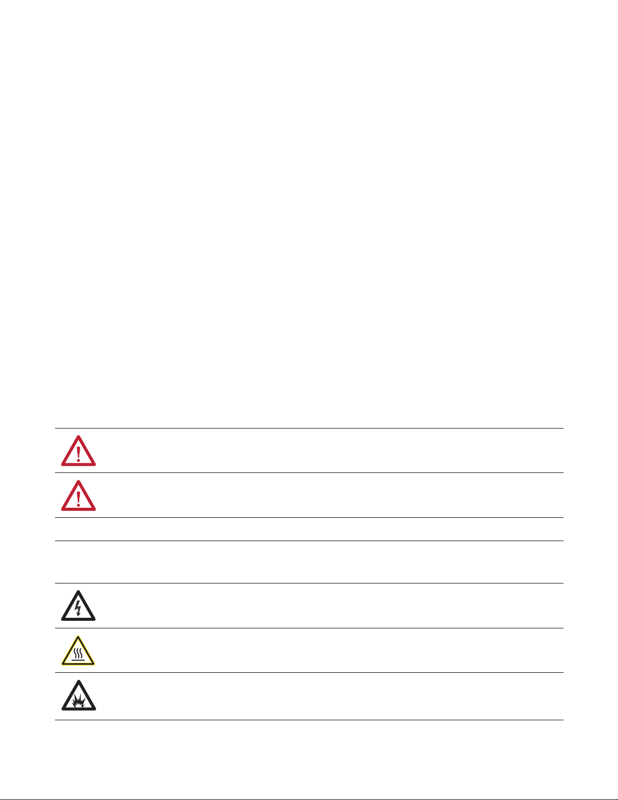
WARNING: Identifies information about practices or circumstances that can cause an explosion in a hazardous environment,
which may lead to personal injury or death, property damage, or economic loss.
ATTENTION: Identifies information about practices or circumstances that can lead to personal injury or death, property
damage, or economic loss. Attentions help you identify a hazard, avoid a hazard, and recognize the consequence.
Identifies information that is critical for successful application and understanding of the product.
Labels may also be on or inside the equipment to provide specific precautions.
SHOCK HAZARD: Labels may be on or inside the equipment, for example, a drive or motor, to alert people that dangerous
voltage may be present.
BURN HAZARD: Labels may be on or inside the equipment, for example, a drive or motor, to alert people that surfaces may
reach dangerous temperatures.
ARC FLASH HAZARD: Labels may be on or inside the equipment, for example, a motor control center, to alert people to
potential Arc Flash. Arc Flash will cause severe injury or death. Wear proper Personal Protective Equipment (PPE). Follow ALL
Regulatory requirements for safe work practices and for Personal Protective Equipment (PPE).
Allen-Bradley, CompactLogix, ControlLogix, Kinetix, Logix5000, MP-Series, RSLogix, Studio 5000 Logix Designer, Studio 5000, Ultra3000, SoftLogix, Rockwell Soft ware, and Rockwell Automation, are trademarks of
Rockwell Automation , Inc
Trademarks not belonging to Rockwell Automation are property of their respective companies.
Page 3

Summary of Changes
This manual contains new and updated information. Changes throughout this
revision are marked by change bars, as shown to the right of this paragraph.
New and Updated Information
This table contains the changes made to this revision.
Top ic Pag e
Studio 5000 Logix Designer™ application is the rebranding of RSLogix™ 5000 software 9
Update connector attachment procedure 34
Update the maximum air pressure rating 37
Updated connector and cable information 39…41
Updated dimension drawing for MP-Series Linear Stages (MPAS-A/B8xxx1/2-VxxSxA) 77
Update cable information 88…90
Rockwell Automation Publication MP-UM001D-EN-P - September 2013 3
Page 4

Summary of Changes
Notes:
4 Rockwell Automation Publication MP-UM001D-EN-P - September 2013
Page 5

Safety
Table of Contents
Preface
About This Publication. . . . . . . . . . . . . . . . . . . . . . . . . . . . . . . . . . . . . . . . . . . . . 9
Who Should Use This Manual . . . . . . . . . . . . . . . . . . . . . . . . . . . . . . . . . . . . . . 9
Studio 5000 Environment . . . . . . . . . . . . . . . . . . . . . . . . . . . . . . . . . . . . . . . . . . 9
Additional Resources . . . . . . . . . . . . . . . . . . . . . . . . . . . . . . . . . . . . . . . . . . . . . 10
Chapter 1
Safety Labels. . . . . . . . . . . . . . . . . . . . . . . . . . . . . . . . . . . . . . . . . . . . . . . . . . . . . 12
Clearances. . . . . . . . . . . . . . . . . . . . . . . . . . . . . . . . . . . . . . . . . . . . . . . . . . . . . . . 13
General Safety . . . . . . . . . . . . . . . . . . . . . . . . . . . . . . . . . . . . . . . . . . . . . . . . . . . 13
Heat . . . . . . . . . . . . . . . . . . . . . . . . . . . . . . . . . . . . . . . . . . . . . . . . . . . . . . . . . . . . 14
Vertical or Inclined Payload . . . . . . . . . . . . . . . . . . . . . . . . . . . . . . . . . . . . . . 14
End of Travel Impacts . . . . . . . . . . . . . . . . . . . . . . . . . . . . . . . . . . . . . . . . . . . . 14
Air Freight Restrictions . . . . . . . . . . . . . . . . . . . . . . . . . . . . . . . . . . . . . . . . . . 14
Standards . . . . . . . . . . . . . . . . . . . . . . . . . . . . . . . . . . . . . . . . . . . . . . . . . . . . . . . 15
Motor Model Identification. . . . . . . . . . . . . . . . . . . . . . . . . . . . . . . . . . . . . . . 15
Understanding Your Linear Stage
Planning Your Installation
Mounting and Connecting
Chapter 2
Identifying Your Linear Stage . . . . . . . . . . . . . . . . . . . . . . . . . . . . . . . . . . . . . 18
Identifying the Components of Your Linear Stage . . . . . . . . . . . . . . . . . . 19
Component Descriptions . . . . . . . . . . . . . . . . . . . . . . . . . . . . . . . . . . . . . 21
Maintenance Intervals . . . . . . . . . . . . . . . . . . . . . . . . . . . . . . . . . . . . . . . . . . . . 22
Lubrication Intervals . . . . . . . . . . . . . . . . . . . . . . . . . . . . . . . . . . . . . . . . . 22
Cable Carrier Replacement . . . . . . . . . . . . . . . . . . . . . . . . . . . . . . . . . . . 22
Chapter 3
General Safety Standards for Linear Stage Installations . . . . . . . . . . 23
UL Safety Standards for Linear Stage Installations. . . . . . . . . . . . . . . 24
Mounting Restrictions . . . . . . . . . . . . . . . . . . . . . . . . . . . . . . . . . . . . . . . 24
Chapter 4
Unpacking, Handling, and Inspection . . . . . . . . . . . . . . . . . . . . . . . . . . . . . 27
Unpacking Procedure. . . . . . . . . . . . . . . . . . . . . . . . . . . . . . . . . . . . . . . . . 28
Store Packaging Material . . . . . . . . . . . . . . . . . . . . . . . . . . . . . . . . . . . . . 30
Linear Stage Storage . . . . . . . . . . . . . . . . . . . . . . . . . . . . . . . . . . . . . . . . . . . . . . 30
Mounting the Linear Stage. . . . . . . . . . . . . . . . . . . . . . . . . . . . . . . . . . . . . . . . 30
Before You Begin the Mechanical Installation. . . . . . . . . . . . . . . . . . . 30
Mount the Linear Stage . . . . . . . . . . . . . . . . . . . . . . . . . . . . . . . . . . . . . . . 33
Connecting the Linear Stage . . . . . . . . . . . . . . . . . . . . . . . . . . . . . . . . . . . . . . 34
Attach the Ground Strap and Interface Cables . . . . . . . . . . . . . . . . . 35
About the Air Option for Ball Screw Linear Stages . . . . . . . . . . . . . . . . . 37
About the Brake Option for Ball Screw Linear Stages . . . . . . . . . . . . . . . 37
Meeting UL Installation Standards for the Linear Stage . . . . . . . . . . . . . 38
Rockwell Automation Publication MP-UM001D-EN-P - September 2013 5
Page 6

Table of Contents
Chapter 5
Connector Data
Configuration Guidelines
Maintenance
Linear Stage Power and Feedback Connections . . . . . . . . . . . . . . . . . . . . . 39
PTC Thermal Signal. . . . . . . . . . . . . . . . . . . . . . . . . . . . . . . . . . . . . . . . . . . . . . 42
Chapter 6
Required Files . . . . . . . . . . . . . . . . . . . . . . . . . . . . . . . . . . . . . . . . . . . . . . . . . . . 43
Configuring Your Linear Stage . . . . . . . . . . . . . . . . . . . . . . . . . . . . . . . . . . . . 43
Configuring the Logix Designer Application for
Linear Stages with Kinetix Multi-axis Drives . . . . . . . . . . . . . . . . 45
Setting Axis Properties in the Logix Designer Application. . . . . . . . 45
Tuning Linear Stages by Using the Logix Designer Application. . . 48
Configuring Ultraware Software for Linear Stages
with Ultra3000 Drives . . . . . . . . . . . . . . . . . . . . . . . . . . . . . . . . . . . . 53
Setting Travel Limits . . . . . . . . . . . . . . . . . . . . . . . . . . . . . . . . . . . . . . . . . . . . . 55
Home to Torque Programming for Kinetix Multi-axis
Drives with Linear Stages . . . . . . . . . . . . . . . . . . . . . . . . . . . . . . . . . . 56
Chapter 7
Before You Begin. . . . . . . . . . . . . . . . . . . . . . . . . . . . . . . . . . . . . . . . . . . . . . . . . 57
Recommended Maintenance Intervals . . . . . . . . . . . . . . . . . . . . . . . . . . . . . 57
Bearing Lubrication . . . . . . . . . . . . . . . . . . . . . . . . . . . . . . . . . . . . . . . . . . . . . . 58
Strip Seal Cleaning . . . . . . . . . . . . . . . . . . . . . . . . . . . . . . . . . . . . . . . . . . . . . . . 59
Cover Cleaning . . . . . . . . . . . . . . . . . . . . . . . . . . . . . . . . . . . . . . . . . . . . . . . . . . 59
Removing and Replacing
Components
Troubleshooting
Dimensions
Chapter 8
Before You Begin. . . . . . . . . . . . . . . . . . . . . . . . . . . . . . . . . . . . . . . . . . . . . . . . . 61
Cable Carrier Assembly Removal . . . . . . . . . . . . . . . . . . . . . . . . . . . . . . . . . . 62
Cable Carrier Assembly Installation . . . . . . . . . . . . . . . . . . . . . . . . . . . . . . . 62
Strip Seal Removal . . . . . . . . . . . . . . . . . . . . . . . . . . . . . . . . . . . . . . . . . . . . . . . 63
Cover Removal. . . . . . . . . . . . . . . . . . . . . . . . . . . . . . . . . . . . . . . . . . . . . . . . . . . 63
Cover Installation . . . . . . . . . . . . . . . . . . . . . . . . . . . . . . . . . . . . . . . . . . . . . . . . 64
Strip Seal Replacement. . . . . . . . . . . . . . . . . . . . . . . . . . . . . . . . . . . . . . . . . . . . 64
Side Cover Installation. . . . . . . . . . . . . . . . . . . . . . . . . . . . . . . . . . . . . . . . . . . . 65
Rotary Motor Replacement . . . . . . . . . . . . . . . . . . . . . . . . . . . . . . . . . . . . . . . 66
Chapter 9
Troubleshooting During Commissioning and Start-up . . . . . . . . . . . . . . 69
Operational Troubleshooting . . . . . . . . . . . . . . . . . . . . . . . . . . . . . . . . . . . . . 70
Direct Drive Linear Stage Evaluation Procedure . . . . . . . . . . . . . . . . 71
Ball Screw Linear Stage Evaluation Procedure . . . . . . . . . . . . . . . . . . . 71
Appendix A
MP-Series Linear Stage Dimensions . . . . . . . . . . . . . . . . . . . . . . . . . . . . 75
6 Rockwell Automation Publication MP-UM001D-EN-P - September 2013
Page 7

Appendix B
Table of Contents
Accessories
Stacking Stages
Interconnect Diagrams
Home to Torque-level Example
Installation, Maintenance, and Replacement Kits . . . . . . . . . . . . . . . . . . . 83
Appendix C
Stage Stacking . . . . . . . . . . . . . . . . . . . . . . . . . . . . . . . . . . . . . . . . . . . . . . . . . . . 85
Specifications for Stacked Stages. . . . . . . . . . . . . . . . . . . . . . . . . . . . . . . . . . . 86
Appendix D
Wiring Examples. . . . . . . . . . . . . . . . . . . . . . . . . . . . . . . . . . . . . . . . . . . . . . . . . 87
Motor/Axis Module Wiring Examples . . . . . . . . . . . . . . . . . . . . . . . . . 88
Appendix E
Applicable Drives . . . . . . . . . . . . . . . . . . . . . . . . . . . . . . . . . . . . . . . . . . . . . . . . 91
About Home to Torque-level Homing. . . . . . . . . . . . . . . . . . . . . . . . . . . . . 92
Drive Bipolar Torque Limit Adjustment . . . . . . . . . . . . . . . . . . . . . . . . . . . 94
Disable Soft Overtravel Limit . . . . . . . . . . . . . . . . . . . . . . . . . . . . . . . . . . . . . 95
Ladder Code Example . . . . . . . . . . . . . . . . . . . . . . . . . . . . . . . . . . . . . . . . . . . . 95
Potential for Position Error . . . . . . . . . . . . . . . . . . . . . . . . . . . . . . . . . . . . . . 102
Appendix F
Mounting Bolts and Torque Values. . . . . . . . . . . . . . . . . . . . . . . . . . . . . . 103
Index . . . . . . . . . . . . . . . . . . . . . . . . . . . . . . . . . . . . . . . . . . . . . . . . . . . . . . . . . . 107
Rockwell Automation Publication MP-UM001D-EN-P - September 2013 7
Page 8

Table of Contents
8 Rockwell Automation Publication MP-UM001D-EN-P - September 2013
Page 9

Read this preface to familiarize yourself with the rest of the manual.
Preface
About This Publication
Who Should Use This Manual
This manual provides detailed installation instructions for mounting, wiring,
maintaining, and troubleshooting your MP-Series integrated linear stage. For
ease of use, going forward, it is referred to as a linear stage.
This manual is intended for engineers or technicians directly involved in the
installation, wiring, and maintenance of linear stages. Any person that teaches,
operates, or repairs these linear stages must be trained and demonstrate the
competence to safely perform the assigned task.
If you do not have a basic understanding of linear stages, contact your local AllenBradley distributor or Rockwell Automation sales representative for information
on available training courses before using this product.
Read this entire manual before you attempt to install a linear stage into your
machine. Doing so familiarizes you with the linear stage components and their
relationship to each other and the system. After installation, check all system
parameters to be sure you have configured your Logix control system properly. Be
sure to follow all instructions carefully and pay special attention to safety
concerns.
Studio 5000 Environment
The Studio 5000™ Engineering and Design Environment combines engineering
and design elements into a common environment. The first element in the Studio
5000 environment is the Logix Designer application. The Logix Designer
application is the rebranding of RSLogix 5000 software and continues to be the
product to program Logix5000™ controllers for discrete, process, batch, motion,
safety, and drive-based solutions.
The Studio 5000 environment is the foundation for the future of Rockwell
Automation® engineering design tools and capabilities. This environment is the
one place for design engineers to develop all of the elements of their control
system.
Rockwell Automation Publication MP-UM001D-EN-P - September 2013 9
Page 10

Preface
Additional Resources
These documents contain additional information concerning related products
from Rockwell Automation..
Resource Description
Kinetix Motion Control Selection Guide, publication GMC-SG001 Provides an overview of Kinetix servo drives, motors, actuators, and motion accessories designed
Kinetix 2000 Multi-axis Servo Drive User Manual, publication
2093-UM001
Kinetix 6000 Multi-axis Servo Drive User Manual, publication
2094-UM001
Logix5000™ Controllers General Instructions Reference Manual, publication 1756-
RM003
ControlLogix System User Manual, publication 1756-UM001 Information on configuring and troubleshooting your ControlLogix controller system
SoftLogix Motion Card Setup and Configuration Manual, publication 1784-UM003 Information on configuring and troubleshooting your SoftLogix PCI card
System Design for Control of Electrical Noise Reference Manual, publication GMC-
RM001
Motion Analyzer is available at
http://www.ab.com/motion/software/analyzer.html
Rockwell Automation Product Certification website, publication available at http://
ab.com/
National Electrical Code. Published by the National Fire Protection Association of
Boston, MA.
Allen-Bradley Industrial Automation Glossary, publication AG-7.1
Drives and Motion Accelerator Toolkit Quick Start, publication IASIMP-QS019 Information on how Bulletin MPAS stages (referred to a gantry A and B in this public ation are
Ultra3000 Digital Servo Drives Installation Manual,
publication 2098-IN003
Ultra3000 Digital Servo Drives Integration Manual,
publication 2098-IN005
Home to Torque-level Example Application Notes,
publication MOTION-AT001
to help make
initial decisions for the motion control products best suited for your system requirements.
How to install, set up, and troubleshoot a Kinetix 2000 drive
How to install, set up, and troubleshoot a Kinetix 6000 drive
The instructions needed to program a Logix5000™ application
Information, examples, and techniques designed to minimize system failures caused by
electrical noise
Drive and motor sizing with application analysis software
For declarations of conformity (DoC) currently available from Rockwell Automation
An article on wire sizes and types for grounding electrical equipment
A glossary of industrial automation terms and abbreviations
used in a drives and motion application.
How to install, set up, and troubleshoot an Ultra™ 3000 drive
Describes Logix Designer application homing routines
You can view or download publications at
http://www.rockwellautomation.com/literature
technical documentation, contact your local Allen-Bradley distributor or
Rockwell Automation sales representative.
10 Rockwell Automation Publication MP-UM001D-EN-P - September 2013
. To order paper copies of
Page 11

Safety
IMPORTANT
Top ic Pa ge
Safety Labels 12
Clearances 13
General Safety 13
Heat 14
Vertical or Inclined Payload 14
End of Travel Impacts 14
Air Freight Restrictions 14
Standards 15
Motor Model Identification 15
Chapter 1
Any person that teaches, operates, maintains, or repairs these linear stages
must be trained and demonstrate the competence to safely perform the
assigned task.
Rockwell Automation Publication MP-UM001D-EN-P - September 2013 11
Page 12
Chapter 1 Safety
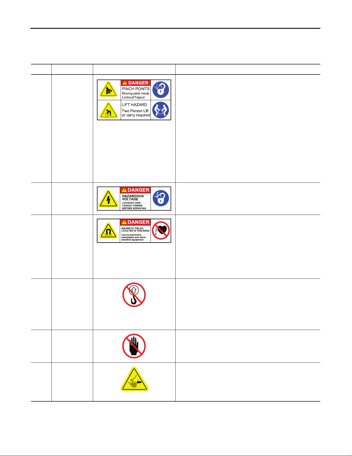
Location Title Label Details
A Danger-Pinch Points
and Heavy Objects
The linear stage presents a muscle strain hazard if one person attempts to
lift it. When attempting to move the linear stage use a two-person-lift to
prevent personal injury or damage to the linear stage.
To Installer - There exists a Crush and Cut hazard while installing the linear
stage. The linear stage weighs from 13…63 kg (28…140 lb).
To User - The Pinch Point label identifies a moving object hazard, caused by
the movement of the carriage on the linear stage. Never put fingers, hands,
or limbs near the linear stage while running motion commands. Before
executing any motion command, check that all maintenance tools have
been removed from linear stage.
All types of linear stages, especially uncovered, present a pinch point
hazard. This hazard may occur if fingers or hands come between the end
cap and a moving carriage. Always lift the linear stage by the base and
keep fingers and hands away from the opening and edges parallel to the
carriage.
B Danger-Hazardous
Voltage
The Hazardous Voltage label identifies the junction box as a hazardous
voltage area of the linear stage. To avoid injury be sure to follow LockoutTagout procedures before attempting maintenance on these linear stages.
C Danger-Strong
Magnets
The Strong Magnets label identifies non-ionizing radiation found in the
linear stage. Magnet channels inside the linear stage are constructed with
strong magnets. Strong magnets can disrupt the functionality of automatic
implantable cardioverter defibrillators (AICD); people with a pacemaker
should not work near the linear stage. Maintenance personnel working on
the linear stage should avoid the use of metallic tools and secure items
such as badge clip and other personal effects that could be attracted by the
strong magnets. Strong magnets can erase magnetic media. Never allow
credit cards or floppy disks to contact or come near the linear stage.
D Do Not Lift by
Junction Box
Do not attempt to move the linear stage by grasping the cable junction box.
Moving the linear stage in this manner will damage the linear stage and
create a pinch or crush hazard. The junction box is attached to the carriage,
which is free to move. Lifting the linear stage in this manner will allow
uncontrolled movement of the heavy base. Always use a two-person lift
and grasp the linear stage by the base at the end caps. Always keep
fingers clear of the carriage’s path of travel.
E Stay Clear
Do not put hands or objects on the linear stage cover. Doing so could
deform the cover and damage the linear stage, causing excessive wear on
the cover supports or scraping noises when the linear stage is in motion.
F Sharp Edges
Always remove strip seals before removing the top or side covers. If it
becomes necessary to remove the top or side covers or change the strip
seal, exercise care when working near or on the strip seal. The edges of
the strip seal are sharp and can cut if accidentally hit or if handled
inappropriately.
Safety Labels
To prevent injury and damage to the linear stage, review the safety labels and the
details and location for each table before using the linear stage.
12 Rockwell Automation Publication MP-UM001D-EN-P - September 2013
Page 13
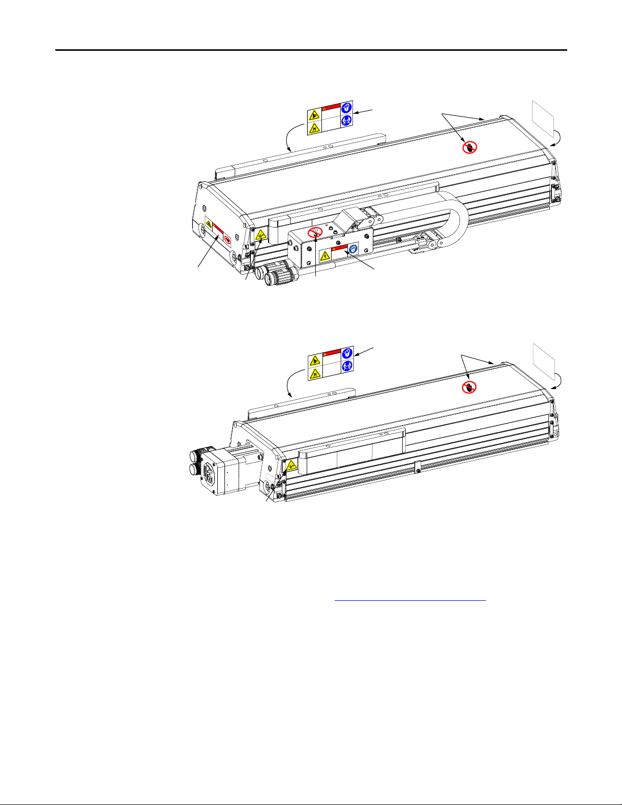
Figure 1 - Label Locations for Direct Drive Linear Stages
E
B
D
Product
Nameplate
A
C
F
LIFT HAZARD
Two Person Lift
or carry required
DANGER
PINCH POINTS
Moving parts ins
ide
Lockout /Tagout
270 kPa
40 PSI
MAXIMUM
PRESSURE
E
Product
Nameplate
A
F
DANGER
PINCH POINTS
oving parts inside
M
Tagout
ockout /
L
LIFT HAZARD
Two Person Lift
or carry required
M
D
A
GN
A
L
O
C
E
N
A
TI
TE
C
G
C
F
D
I
a
E
I
n
ER
N
L
p
D
be
TH
a
S
c
e
h
s
I
m
S
en
a
r
A
a
mf
s
k
R
i
t
e
E
i
r
u
v
A
s
e
l
a
to
equ
n
d
o
i
pm
t
h
e
e
r
n
t
R
GE
AN
D
S
U
O
D
R
A
Z
HA
E
G
A
T
L
O
V
D
AN
T
U
CKO
LO
R
E
W
PO
T
U
O
AG
G
T
N
CI
VI
R
E
S
E
R
O
F
E
B
Figure 2 - Label Locations for Ball Screw Linear Stages
Safety Chapter 1
Clearances
Install the linear stage to avoid interference with the building, structures, utilities,
other machines and equipment that can create a trapping hazard of pinch points.
General Safety
Dress cables by using the Clearance Requirements on page 26
cross the path of motion or interfere with the cable carrier motion.
Linear stages are capable of sudden and fast motion. In no event will Rockwell
as a guide. Do not
Automation, Inc. be responsible or liable for indirect or consequential damages
resulting from the use or application of this equipment.
Rockwell Automation Publication MP-UM001D-EN-P - September 2013 13
Page 14

Chapter 1 Safety
Heat
Vertical or Inclined Payload
End of Travel Impacts
When the stage is running at its maximum rating, the temperature of the carriage
can reach 75
A direct drive (linear motor driven) linear stage mounted vertically or on an
incline does not maintain position when the power is removed. Under the
influence of gravity the carriage and its payload falls to the low end of travel.
Design engineers must account for this by using a ball screw driven linear stage
with power-off holding brake, or designing in controlled power down circuits or
mechanical controls to prevent the linear stage and its payload from being
damaged when the power fails.
The internal bumpers of the linear stage are designed to take a large impact from
uncontrolled motion. Setting Travel Limits on page 55
bumpers can absorb before risking damage to the linear stage. The carriage
payload must be secured to the carriage such that it does not sheer off in the event
of an impact in excess of the bumper ratings.
The bolts securing the end caps are not be able to sustain multiple impacts and
can eventually sheer. Correct the cause of the uncontrolled motion that caused
the impact before continuing the use of the linear stage.
ºC (167 ºF).
lists the energy that the
Air Freight Restrictions
When air freighting linear stages special preparations and precautions must be
taken. The following information outlines the basic requirements at the
publication date of this document. However, regulations are subject to change
and additional area or carrier restrictions can be imposed. Always check with your
carrier or logistics specialist regarding current local, regional, and national
transportation requirements when shipping this product.
The 200 mm or a 250 mm direct drive linear stages (catalog numbers MPASA8xxxE-ALMx2C, MPAS-B8xxxF-ALMx2C, MPAS-A9xxxK-ALMx2C, or
MPAS-B9xxxL-ALMx2C) contain magnetized material, as classified by
International Air Transport Association (IATA) Dangerous Goods Regulations.
An IATA trained individual must be involved when shipping this product via
domestic or international air freight. Packing Instruction 902 provides
information regarding the preparation of this product for air transportation.
Follow these regulations for general marking and labeling requirements, the
application of specific Magnetized Material Handling Labels, and instructions
for preparing the Shipper's Declaration for Dangerous Goods.
14 Rockwell Automation Publication MP-UM001D-EN-P - September 2013
Page 15

Safety Chapter 1
As a minimum, refer to the following IATA Dangerous Goods Regulations:
• Subsection 1.5: Training
• Subsection 3.9.2.2: Classification as Magnetized Material
• Subsection 4.2: Identification as UN 2807, Magnetized Material, Class 9,
Packing Instruction 902
• Subsection 7.1.5: Marking
• Subsection 7.2: Labeling
• Subsection 7.4.1: Magnetized Material Label
• Section 8: Shipper's Declaration for Dangerous Goods
When shipped via ground in the United States, these products are not considered
a U.S. D.O.T. Hazardous Material and standard shipping procedures apply.
Standards
Motor Model Identification
Standards and requirements applicable to this product include, but are not
limited to, the following:
· ANSI/RIA R15.06, Industrial Robots and Robot Systems Safety
Requirements - Teaching Multiple Robots
· ANSI/NFPA 79, Electrical Standard for Industrial Machinery
· CSA/CAN Z434, Industrial Robots and Robot Systems- General Safety
Requirements
· EN60204-1, Safety of Machinery. Electrical Equipment of Machines
· UL 1740, UL Standard for Safety Industrial Robots and Robotic
Equipment
The nameplate on ball screw driven linear stages lists the specific MP-Series servo
motor model used.
Rockwell Automation Publication MP-UM001D-EN-P - September 2013 15
Page 16

Chapter 1 Safety
Notes:
16 Rockwell Automation Publication MP-UM001D-EN-P - September 2013
Page 17

Understanding Your Linear Stage
Top ic Pa ge
Identifying Your Linear Stage 18
Identifying the Components of Your Linear Stage 19
Maintenance Intervals 22
Chapter 2
Rockwell Automation Publication MP-UM001D-EN-P - September 2013 17
Page 18

Chapter 2 Understanding Your Linear Stage
MPAS - x x xxx x - x xx x x x
Voltage C lass
A = 200V
B = 400V
Actuator Type
AS = Actuator, linear stage
Frame Size
(2)
6 = 150 mm base width
8 = 200 mm base width
9 = 250 mm base width
Stroke Length
(1)
xxx = xxx mm x 10
Mechanical Drive/Motor Typ
1 = Ballscrew/MPLS-x210E-V 2 = Ballscrew/MPLS-x220H-V
B = Direct Drive/6-frame, 200V-class K = Direct Drive/9-frame, 200V-class
E = Direct Drive/8-frame, 200V-class L = Direct Drive/9-frame, 400V-class
F = Direct Drive/8-frame, 400V-class
Feedback
V = Multi-turn high-resolution encoder (absolute feedback) 128 cycle/rev. (ballscrew only)
A = 5 micron resolution incremental magnetic linear encoder (direct drive only)
Screw Lead/Direct Drive
05 = 5.0 mm/rev (0.19 in./rev) ballscrew with rotary motor
20 = 20.0 mm/rev (0.79 in./rev) ballscrew with rotar y motor
LM = Linear motor (direct drive only)
Brake
2 = No brake
4 = 24V DC brake (ballscrew only)
Cable
A = No cable track module (ballscrew only)
C = Cable track module with IP67 intercontec connectors (direct drive only)
Cover
S = Covered with strip seals (IP30 protection)
O = Open
Actuator Series
MP = MP-Series
Identifying Your Linear Stage
Use the following key to identify your linear stage and its options.
(1) For 6-frame direct-drive linear stages, variable xxx (mm stroke x 10) is 012, 018, 024, 030, 036, 042, 054, 066, 078, 090, 102, or 114.
For 8 and 9-frame direct-drive linear stages, variable xxx (mm stroke x 10) is 014, 020, 026, 032, 038, 044, 056, 068, 080, 092, 104, 128, 152, 176, or 194.
For 6-frame ballscrew linear stages, variable xxx (mm stroke x 10) is 012, 018, 024, 030, 036, 042, 054, or 066.
For 8 and 9-frame ballscrew linear stages, variable xxx (mm stroke x 10) is 012, 018, 024, 030, 036, 042, 054, 066, 078, 090, or 102.
(2) The 150 mm (6-frame) linear stages are available in ballscrew (200 and 400V-class) and direct drive (200V-class only).
The 200 mm (8-frame) linear stages are available in ballscrew and direct drive (200 and 400V-class).
The 250 mm (9-frame) linear stages are available in ballscrew and direct drive (200 and 400V-class).
18 Rockwell Automation Publication MP-UM001D-EN-P - September 2013
Page 19
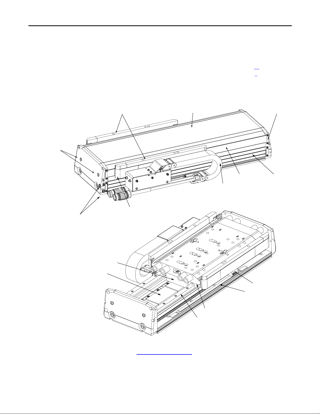
Understanding Your Linear Stage Chapter 2
7 (2x)
6
8 (4x)
9 (4x)
2 (4x)
4
3
1
5 (2x)
10
11
12 (4x)
13 (2x)
14
15
Identifying the Components of Your Linear Stage
Use the diagrams and descriptions to identify individual components of the
linear stages.
Not all components are part of the direct drive or the ball screw linear stage. For
example, the direct drive linear stage does not have component 20
Motor and the ball screw linear stage does not have component 6
- Rotary
- Cable Carrier
Module.
Figure 3 - Components of the Direct Drive Linear Stage (MPAS-xxxxxxx-ALMx2C)
Refer to Component Descriptions beginning on page 21 for the name and
description of each numbered item.
Rockwell Automation Publication MP-UM001D-EN-P - September 2013 19
Page 20
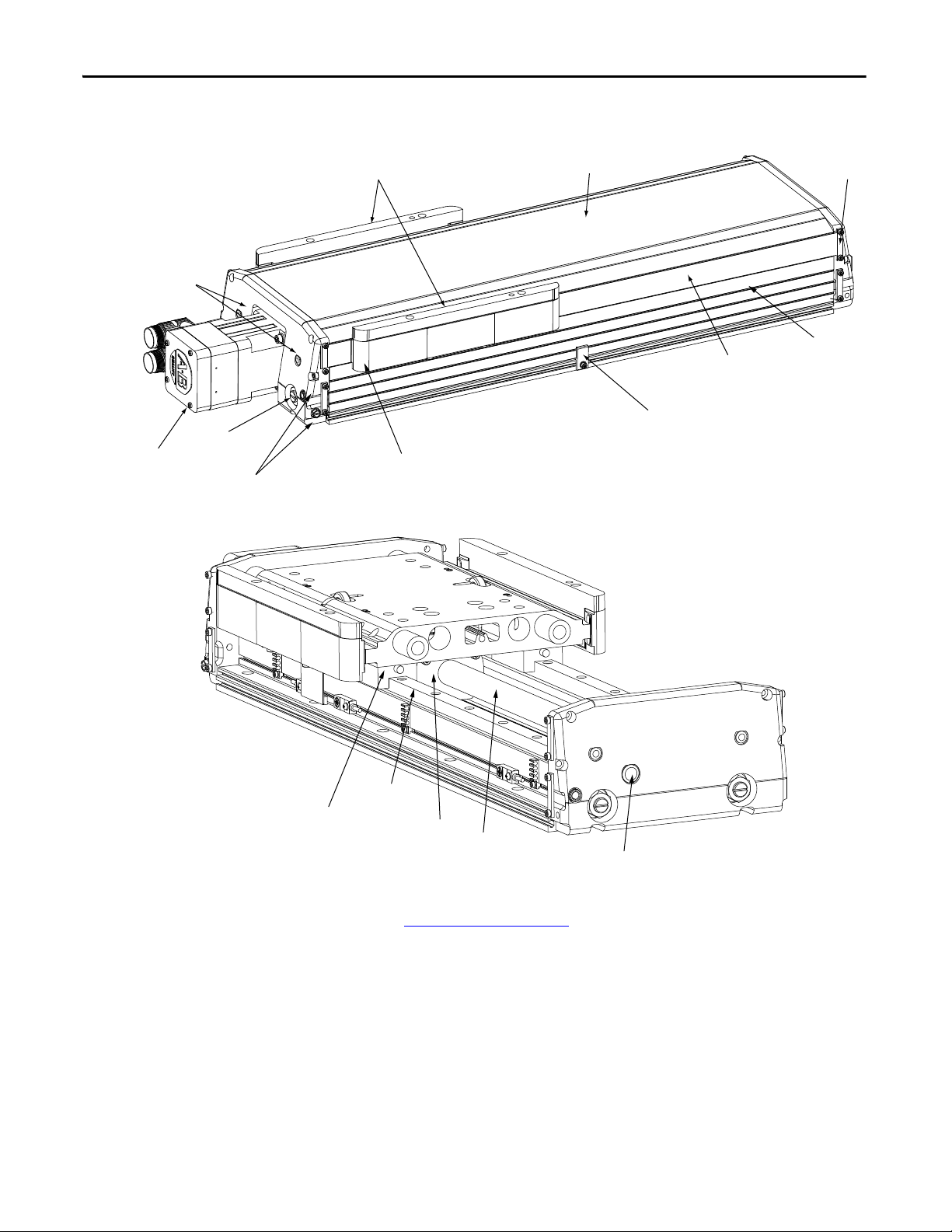
Chapter 2 Understanding Your Linear Stage
18
17
19
20
16
12 (4x)
13 (2x)
7 (2x)
8 (4x)
9 (4x)
2 (4x)
4
3
1
5 (2x)
21
Figure 4 - Components of the Ball Screw Linear Stage (MPAS-xxxxxx-VxxSxA)
Refer to Component Descriptions beginning on page 21 for the name and
description of each numbered item.
20 Rockwell Automation Publication MP-UM001D-EN-P - September 2013
Page 21

Understanding Your Linear Stage Chapter 2
Component Descriptions
Item Name Notes
1 Ground Screw and Ground Label Use the labeled M5 x 0.8 - 6H ground screw to connect the linear stage to a facility safety ground.
2 Bearing Lubrication Ports These capped ports provide access to the linear bearings without dismantling the linear stage. In addition, these
. Carriage
4 Top Cover This protective cover has magnetic edges that keep the upper edge of the strip seals in place. A cover is an option on
5 Side Cover These protective covers have magnetic edges that keep the lower edge of the strip seal in place. Side covers are an
6 Cable Carrier Module This assembly contains the power an d I/O wiring for direct drive linear stages. It facili tates quick and easy replacement
7 Stainless Steel Strip Seal These replaceable flexible stainless steel strips permit the linear stage to move while isolating the internal mechanism
8 Seal Guide These guides lets the strip seal to move smoothly around the carriage of the linear stage.
9 Seal Strip Clamps These clamps hold the strip seal in place. When replacing the seal strips, they are used to position it so it lays smooth
10 Magnetic Encoder Readhead This encoder readhead has a 5 micron resolution and very low maintenance needs.
11 Encoder Strip Part of the encoder system that provides magnetic encoded polarities to the encoder readhead.
12 Bearing These support bearings guide the carriage on the bearing rail and require periodic lubrication.
13 Bearing Rail These rails provide the linear track that the carriage assembly rides on, they must be kept free of debris.
14 Motor Coil This coil is par t of the two piece linear motor. When it is excited by a drive, it generates magnetic forces that interact
15 Magnet Track This track of powerful static magnets is the other half of a linear motor.
16 Ball Nut Lubrication Port This capped ports provide access to the ball nut without dismantling the linear stage.
17 Ball Screw Shaft This is part of the mechanical power system on ball screw linear stages. This shaft must be kept free of debris.
18 Ball Nut Transfers mechanical power from the ball screw shaft to the carriage. It requires periodic lubrication.
19 Side Cover Support These supports stabilize the side cover on long linear stages.
20 Rotary Motor A Rockwell Automation MPLS rotary motor drives the ball screw mechanis m. It is a specially configured MP-Series
21 Air Port Provides an external air supply connection for a ball screw linear stage. A maximum of 270 kPa (40 psi) of pressurized
This is where your load mounts. The carriage has both mounting holes and pilot guide holes.
tapped holes (M10 x 1.5 -6H) can be used to secure lifting hooks (not provided).
the direct drive linear stages.
option on the direct drive linear stages.
of this wear item. It is available as a spare part.
of the linear stage from the users environment. Keep the strip seals clean, and never apply a lubricant as this attracts
contaminants.
against the top and side covers.
with the magnet track creating motion.
rotary motor, and is available as a spare part.
air can be applied to minimize the ingress of particulates from a dusty environment.
Rockwell Automation Publication MP-UM001D-EN-P - September 2013 21
Page 22

Chapter 2 Understanding Your Linear Stage
Maintenance Intervals
This section lists typical maintenance intervals for your linear stage, and
references the section where maintenance procedures are described.
Lubrication Intervals
Refer to the Chapter 7 for lubrication procedures. The following lubrication
intervals are recommended.
• Direct drive linear stages every 6 months or 5000 km of travel
• Ball screw linear stages every 3 months or 150,000,000 revolutions
Cable Carrier Replacement
The cable carrier module’s useful lifetime is approximately 10,000,000 cycles.
Refer to the Chapter 8
for removal and replacement procedures.
22 Rockwell Automation Publication MP-UM001D-EN-P - September 2013
Page 23

Chapter 3
Planning Your Installation
Top ic Pa ge
General Safety Standards for Linear Stage Installations 23
UL Safety Standards for Linear Stage Installations 24
Mounting Restrictions 24
Requirements to be met when mounting your linear stage include the following.
General Safety Standards for Linear Stage Installations
General safety standards and requirements include, but are not limited to, the
following:
• ANSI/RIA R15.06, Industrial Robots and Robot Systems Safety
Requirements - Teaching Multiple Robots
• ANSI/NFPA 79, Electrical Standard for Industrial Machinery
• CSA/CAN Z434, Industrial Robots and Robot Systems- General Safety
Requirements
• EN60204-1, Safety of Machinery. Electrical Equipment of Machines
Rockwell Automation Publication MP-UM001D-EN-P - September 2013 23
Page 24

Chapter 3 Planning Your Installation
UL Safety Standards for Linear Stage Installations
All linear stage installations must follow UL 1740 - Standard for Safety for
Robots and Robotic Equipment.
UL 1740 covers robots and robotic equipment rated at 600V or less and intended
for installation in accordance with the National Electrical Code, ANSI/NFPA
70. Because end user installation of a robot and robotic equipment can vary for
each user application, guidelines for end-product installation can be evaluated to
the applicable sections of ANSI/RIA R15.06, Standard for Industrial Robots and
Robot Systems-Safety Requirements. Portions of the requirements in this
standard have been excerpted from the Robotic Industries Association's (RIA)
Standard for Industrial Robots and Robot Systems – Safety Requirements,
ANSI/RIA R15.06.
ANSI/RIA R15.06 specifically requires two safety features be in the design.
• A Power Enable light must be installed that meets all of these conditions:
– Must be amber or yellow in color.
– Must not have a screw type base or contain a filament.
– Must be visible from all approaches to the work cell.
– Must illuminate to indicate that drive power is available and motion is
possible.
For example, an Allen-Bradley 855T Control Tower Stack Light can be
used with socket mount status indicators. Incandescent bulbs are not
permitted.
• Provide a means of emergency movement without drive power available.
This must include a provision for a brake release on a ball screw linear
stage.
For additional information, refer to the Emergency Brake Release for Ball
Screw Linear Stage Example on page 38.
Unique features or functions associated with the robotic application, not
specifically addressed in UL 1740, shall also be evaluated to other applicable
standards and requirements. These can include, but are not limited to the
following:
• UL 3101-1, Electrical Equipment for Laboratory Use; Part 1: General
Requirements
• UL 544, Medical and Dental Equipment
• UL 79, Power Operated Pumps for Petroleum Product Dispensing
Systems
• ANSI/NFPA 79, Electrical Standard for Industrial Machinery
Mounting Restrictions
When locating your MPAS stage include the following:
24 Rockwell Automation Publication MP-UM001D-EN-P - September 2013
Page 25

Planning Your Installation Chapter 3
• Environmental Factors
• Mounting Surface Restrictions
• Mounting Orientations for Direct Drive Linear Stages
• Mounting Orientations for Ball Screw Linear Stages
• Clearance Requirements
Environmental Factors
Factor Applicability
Temperature The linear stage does not require any special cooling considerations. Avoid mounting it near any heat generating objects, such as a heat
Humidity Avoid excessive humidity that can cause condensation on metal surfaces and consequently stage corrosion. The maximum permissible
Access and interference When possible, locate the system where sufficient working space is available to perform periodic maintenance.
Dust and airborn e contaminants Avoid placing the stage in areas where excessive dust or other airborne contaminants are present. Chemical fumes or vapors can cause damage
Vibration The linear stage must be installed in a location free of excessive vibration.
Ambient light Sufficient light must be readily available to enable inspection, testing, and other functions to be performed on the stage.
register. Sustained average operating temperature must not be greater than 40 °C (104 °F), nor less than 0 °C (32 °F).
noncondensing humidit y is 80% relative.
Avoid installing where a trapping hazard or pinch point occurs as a result of interference with the building, structures, utilities, and other
machines and equipment.
to internal compon ents.
Mounting Surface Restrictions
Surface Restriction
Flatness Stages are to be bolted or clamped to a flat, stable, and rigid surface along its entire length. Flatness deviation in the mounting surface must
be less than or equal to 0.025 mm over a 300 x 300 mm (0.001 in. over a 12 x 12 in.) area.
Flatness must be maintained during operation of the linear stage.
Mounting Orientations for Direct Drive Linear Stages
Mounting Orientation Restriction
Ceiling - inverted surface A ceiling mount (inverted on a horizontal surface) is not recommended. Stages mounted in this orientation are subject to premature cable
Wall - horizontal Horizontal wall mount stages must be of the covered and sealed configuration.
Wall - vertical or incline Vertical wall mount or inclined stages must be of the covered and sealed configuration.
carrier failure.
Stages mounted horizontally on a wall must have a travel of 1 m (3.28 ft) or less. Stages with a travel length greater than 1 m (3.28 ft) are
subject to premature cable carrier failure.
Stages mounted vertically on a wall must have a travel of 1 m (3.28 ft) or less. Stages with a travel length greater than 1 m (3.28ft) are subject
to premature cable carrier failure.
Rockwell Automation Publication MP-UM001D-EN-P - September 2013 25
Page 26
Chapter 3 Planning Your Installation
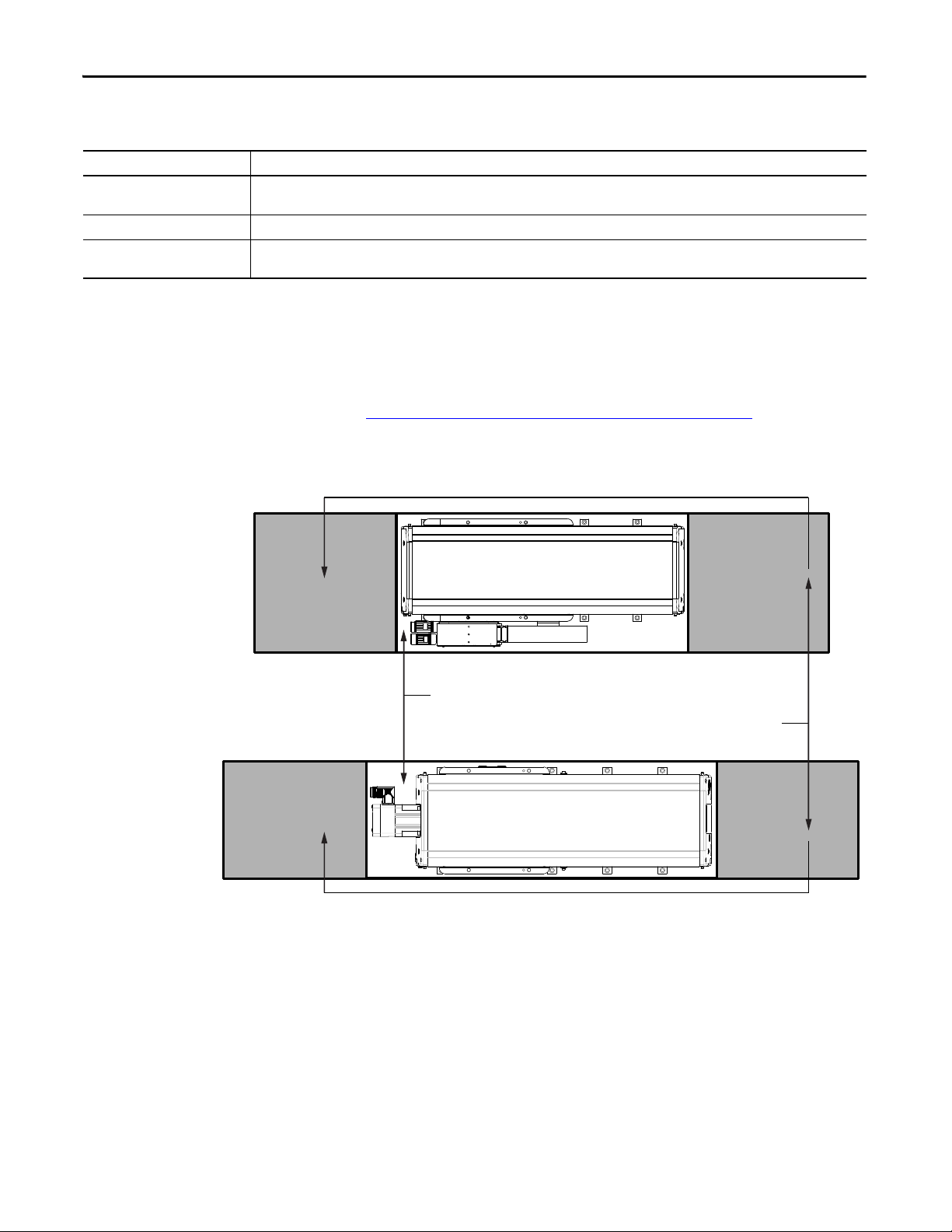
419 mm (16.5 in.) Clearance Both Ends for Lubrication Access
3.2 mm (0.125 in.) Clearance Around Entire Stage
MPAS-xxxxxxx-ALMx2C
MPAS-xxxxxxx-VxxSxA
Additional clearance is required for power
and feedback cables.
Mounting Orientations for Ball Screw Linear Stages
Mounting Orientation Restriction
Ceiling - inverted surface A ceiling mount (inverted on a horizontal surface) must be of the covered and sealed configuration, and have a travel of 300 mm (11.8 in.) or
Wall - horizontal A horizontal wall mount stages must be of the covered and sealed configuration.
Wall - vertical or incline Vertical wall mount or inclined stages must have a brake option. Application of the holding brake option through operating program settings
less.
prevents uncontrolled motion.
Clearance Requirements
The figures depict the minimum clearances for each stage type.
Power and feedback cables can impose additional clearance requirements. Refer
to Installation, Maintenance, and Replacement Kits on page 83
and bend radius requirements.
Figure 5 - Minimum Clearance Requirements
for connector
26 Rockwell Automation Publication MP-UM001D-EN-P - September 2013
Page 27
Mounting and Connecting
IMPORTANT
Top ic Pa ge
Unpacking, Handling, and Inspection 27
Linear Stage Storage 30
Mounting the Linear Stage 30
Connecting the Linear Stage 34
About the Air Option for Ball Screw Linear Stages 37
About the Brake Option for Ball Screw Linear Stages 37
Meeting UL Installation Standards for the Linear Stage 38
Chapter 4
Unpacking, Handling, and Inspection
Any person that teaches, operates, maintains, or repairs these linear stages
must be trained and demonstrate the competence to safely perform the
assigned task.
Inspect packaging to make certain no damage has occurred in shipment. Any
damage or suspected damage must be immediately documented. Claims for
damage due to shipment are usually made against the transportation company.
Contact Allen-Bradley immediately for further advice.
Be sure the information listed on the purchase order correlates to the information
on the packing slip for your linear stage and its accessories. Inspect the assemblies
and confirm, if applicable, the presence of specified options.
ATT EN TI ON : Direct drive linear stages contain powerful permanent magnets
that require extreme caution during handling. Do not disassemble the linear
stage. The forces generated by permanent magnets are very powerful and can
cause bodily injury.
Persons with pacemakers or automatic implantable cardiac defibrillators
(AICD) must maintain a minimum distance of 0.3 m (12 in.) from magnet
assemblies.
Additionally, unless absolutely unavoidable, a minimum distance of 1.5 m (5 ft)
must be maintained between magnet assemblies and other magnetic or ferrous
composite materials. Calipers, micrometers, laser equipment, and other types of
instrumentation must be nonmetallic.
Rockwell Automation Publication MP-UM001D-EN-P - September 2013 27
Page 28
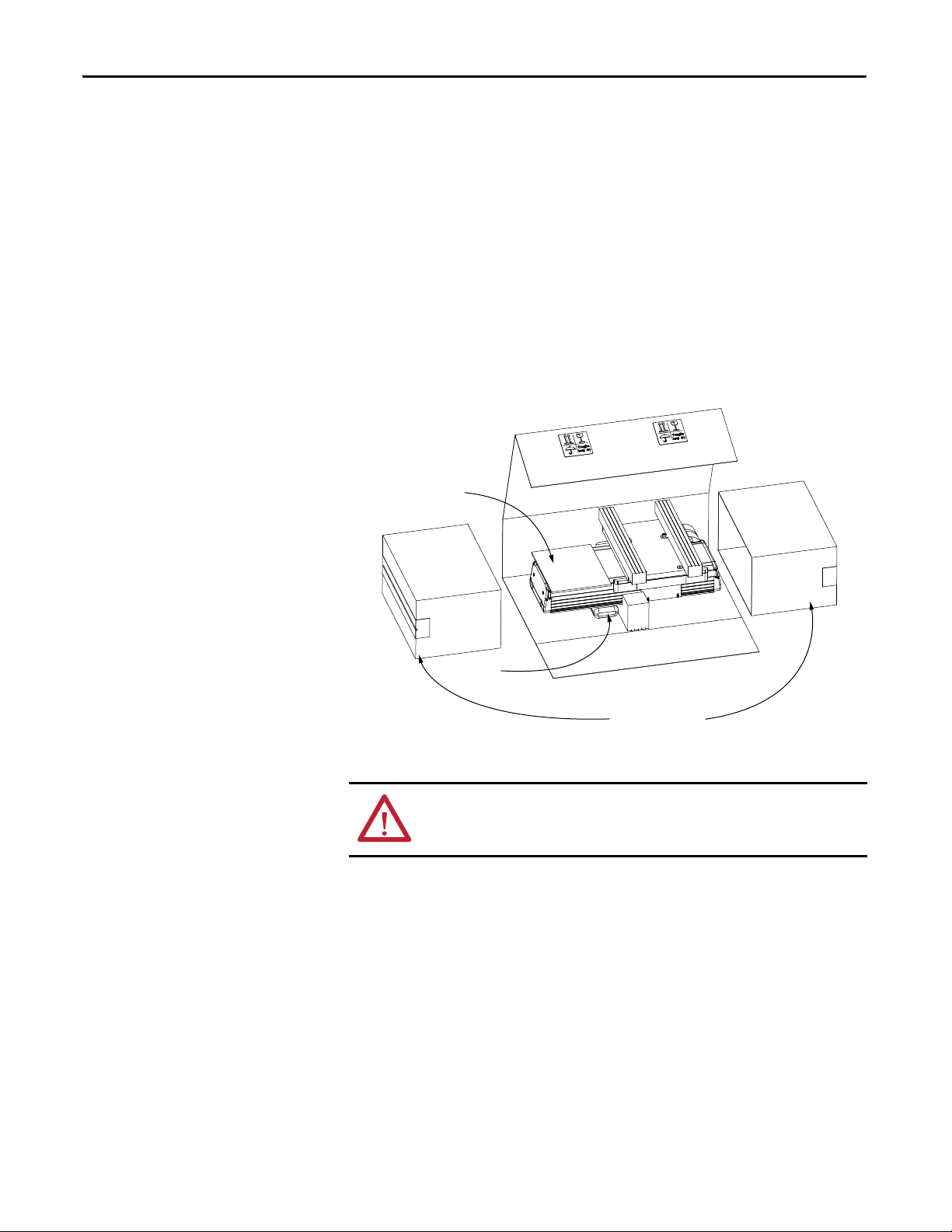
Chapter 4 Mounting and Connecting
User Manual
Packing End Caps
Desiccant
Unpacking Procedure
The following tools are recommended for unpacking the linear stage:
• Utility knife
• 2.5mm, 5mm, and 6mm hex keys
• Packing tape
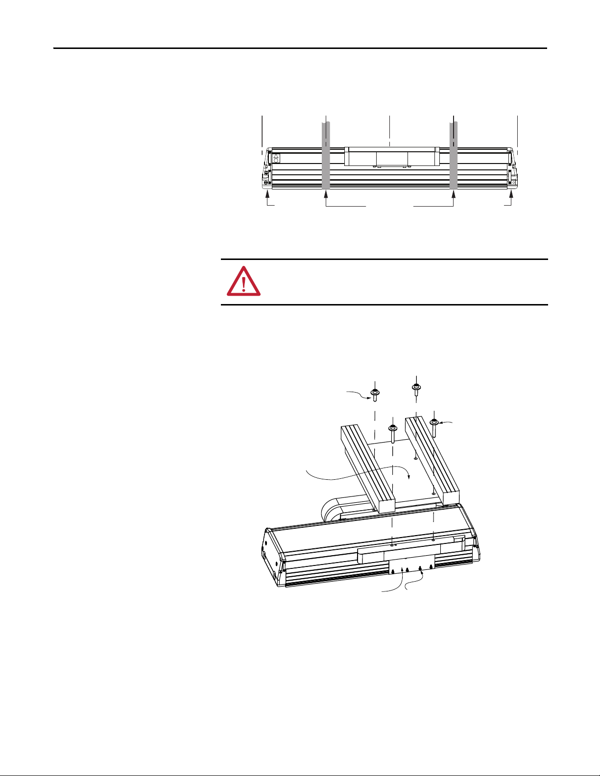
Unpack your linear stage by doing the following.
1. Place the carton on a flat stable surface with the tape seam side facing you.
2. Use a utility knife to score the packing tape at the edges of the carton.
3. Lift center cover to reveal the linear stage.
4. Remove the packing end caps.
ATT EN TI ON : Never attempt a single-person lift.
Personal injury and equipment damage can occur if the linear stage is handled
improperly
5. Remove the linear stage from the packaging supports.
• For stages shorter than 1 meter (39.3 in.), use two people and lift the
linear stage by grasping only the base near the end caps.
28 Rockwell Automation Publication MP-UM001D-EN-P - September 2013
Page 29
Mounting and Connecting Chapter 4
Support Straps
1/4 1/4 1/4 1/4
End Cap End Cap
Shipping Brace
3M SHCS, washer, and nut (x4)
Shipping Clamp
M6 x 75 SHCS (x2) for
MPAS-x6xxxxx (150 mm)
M6 x 75 SHCS (x2) for
MPAS-x8xxxxx (200 mm) or
MPAS-x9xxxxx (250 mm)
M6 x 30 SHCS (x2) for
MPAS-x6xxxxx (150 mm)
M8 x 30 SHCS (x2) for
MPAS-x8xxxxx (200 mm) or
MPAS-x9xxxxx (250 mm)
• For stages 1 meter (39.3 in.) or longer, use support straps at the 1/4
and 3/4 length points to avoid distorting the base. Use this support
system whenever the linear stage must be lifted.
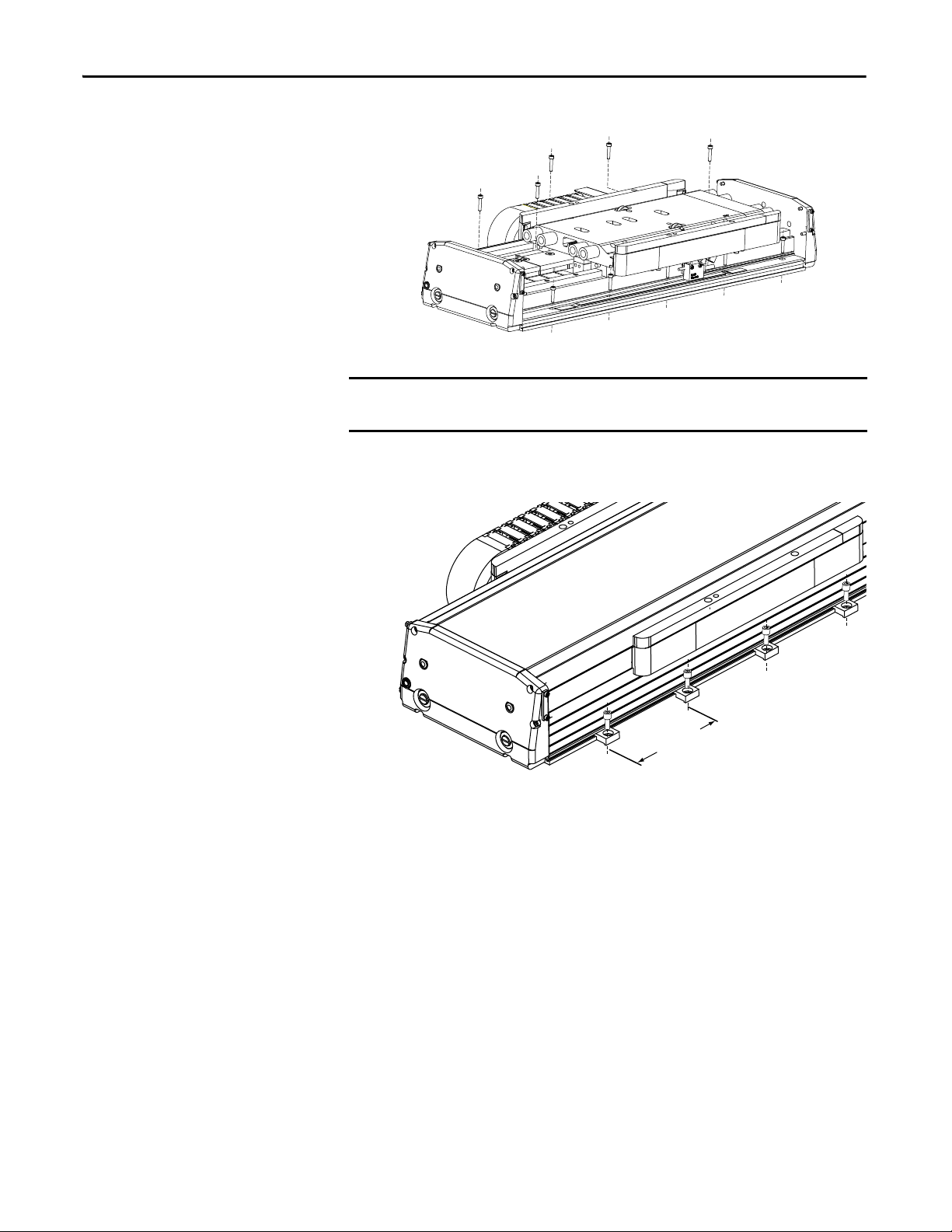
6. Move the linear stage to a solid support surface before removing the
shipping brace.
ATT EN TI ON : The carriage is free to move once the shipping brace is removed.
Use additional care when handling the linear stage after the brace is removed.
Unexpected carriage movement can cause personal injury.
7. Remove the four socket-head cap screws (SHCS) from the shipping brace.
The figure below lists the correct hex wrench for each linear stage.
8. Lift the shipping brace off the linear stage and set it aside.
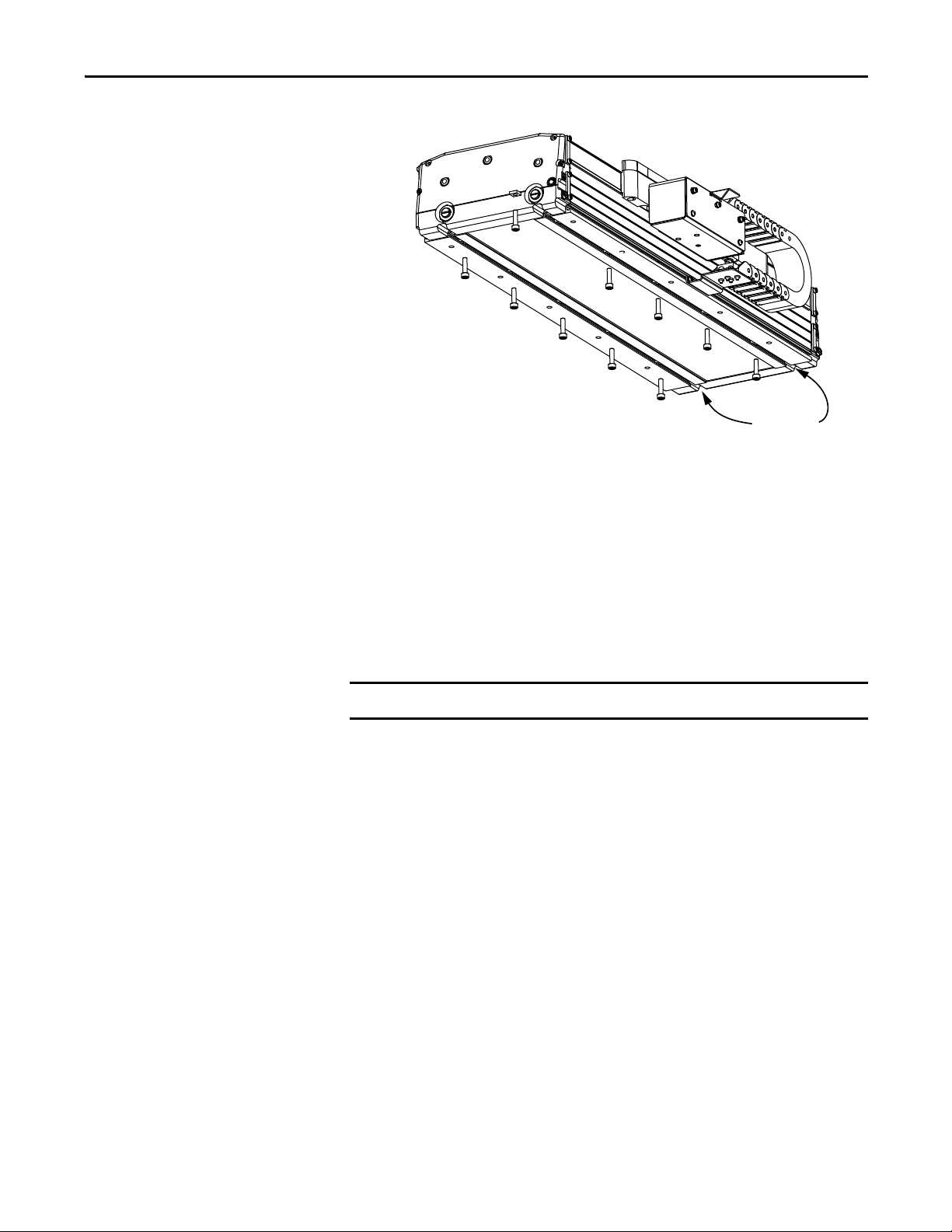
9. Remove the plastic wrap enclosing the linear stage and set it aside.
10. Remove the four SHCS that secure the shipping clamp.
11. Remove the four square nuts loosened in the previous step, by sliding each
Rockwell Automation Publication MP-UM001D-EN-P - September 2013 29
nut to the end of channel.
Page 30

Chapter 4 Mounting and Connecting
fasteners
stroke (cm) + 36 (cm)
12
----------------------------------------------------
round down 1+
2×=
fasteners
stroke (cm) + 26 (cm)
12
----------------------------------------------------
round down 1+
2×=
Store Packaging Material
Keep the carton and packing materials in case the linear stage needs to be
returned for warranty service or stored for an extended period of time.
1. Tape screws and clamp hardware to the plywood board brace.
2. Put the end caps in their original positions on the center cover and place all
packing material inside the carton.
3. Lightly tape carton closed and store in a dry place.
Linear Stage Storage
Mounting the Linear Stage
The linear stage storage area must be clean, dry, vibration free, and have a
relatively constant temperature. Refer to Environmental Specifications for MPSeries Linear Stages in the Kinetix Linear Motion Specifications Technical Data
GMC-TD002
for more detailed information.
This section discusses mounting methods and procedures for both linear stage
types.
Before You Begin the Mechanical Installation
The machine designer is the best person to determine the number and type of
fasteners to use when mounting your linear stage The following information is
supplied to assist in your decision-making.
Determine the Number of Fasteners Required
The length of the linear stage determines the number of mounting fasteners that
are required.
Use one of the following equations to calculate the required mounting hardware.
Figure 6 -
Figure 7 -
30 Rockwell Automation Publication MP-UM001D-EN-P - September 2013
Fasteners Required for Direct Drive Linear Stage (MPAS-
Fasteners Required for Ball Screw Linear Stage (MPAS-
xxxxxxx
-ALMx2C)
xxxxxxx- VxxSx
A)
Page 31

Mounting and Connecting Chapter 4
fasteners 19 1+202× 40 fasteners===
1940 mm strokelength 194.0cm=
fasteners
194 cm + 36
12
--------------------------------
230
12
---------
19.167===
round down 19=
For example, if you are mounting an MPAS-B8194F-ALM02C linear stage.
Determine the Type of Fastener to Use
There are three types of fasteners that can be used to mount the linear stage:
• Through bolt
• To e c li p
• Te e n ut
Toe clips are supplied with the catalog number MPAS-x6xxx linear stages, and
covered types of the catalog number MPAS-x8xxx and MPAS-x9xxx linear stages.
Refer to the following table for an illustration of each fastener type.
Table 1 - Mounting Fastener Options
Fasten er Catalog Number Illustration User Supplies
Through bolt
Toe clip MPAS-TOE M6 x 1.0 x16mm (min) Covered stages
Tee nut
(1) Through bolt mounting is not an option for the catalog number MPAS-x6xxxx-xxxxx (150 mm) linear stages.
(2) The Tee nut mount for a catalog number MPAS-x8xxxx-xxxxx (200 mm) linear stage is a square nut in a T-slot.
(3) Where x is the frame size of a stage, 6 = MPAS-x6xxxx-xxxxx (150 mm), 8 = MPAS-x8xxxx-xxxxx (200 mm), 9 = MPAS-x9xxxx-xxxxx (250 mm).
(4) You supply the bolts.
(1)
—
(2)
MPAS-x-TNU T
(3)
M5 x 1.0 x 16 mm (min) Uncovered stages
M6 x 1.0 Securing a linear stage from beneath the mounting surface
(4)
Recommended For
Rockwell Automation Publication MP-UM001D-EN-P - September 2013 31
Page 32
Chapter 4 Mounting and Connecting
IMPORTANT
120 mm
(4.72 in.)
Figure 8 - Through Bolt Mounting
Through bolt mounting is not available for the catalog number MPASx6xxxx-xxxxx (150 mm) stages.
An uncovered linear stage is a good candidate for through bolt mounting.
Figure 9 - Toe Clip Mounting
For covered linear stages, toe clips are the easiest method for mounting. On both
sides of the base, secure a toe clip every 120 mm (4.72 in.) with a M6 SHCS as
shown in Figure 9. Use the slots formed into the outside edge of the linear stage
base.
32 Rockwell Automation Publication MP-UM001D-EN-P - September 2013
Page 33
Mounting and Connecting Chapter 4
IMPORTANT
T-Slots
Figure 10 - Tee Nut Mounting
Tee nuts are used to mount the linear stage from underneath. Insert the Tee nuts
every 120 mm (4.72 in.) in both T-slots on the bottom of the linear stage. Secure
the Tee nuts by using M6 SHCS as shown in Figure 10.
Mount the Linear Stage
Follow these steps to install a linear stage on its mounting surface.
1. Be sure the mounting surface is clear of any and all foreign material.
Do not use abrasives to clean the surface.
If necessary, stone the mounting surface (acetone or methanol can be
applied as cleaning agent).
2. Verify the flatness of the mounting surface.
The total indicator reading (TIR) is 0.0254 mm (0.001 in.) per 300 mm
(12 in.). TIR or runout, correlates to an overall flatness of a surface .
Rockwell Automation Publication MP-UM001D-EN-P - September 2013 33
Page 34
Chapter 4 Mounting and Connecting
ATT EN TI ON : Do not attempt to move the linear stage by grasping the cable
junction box. Moving the linear stage in this manner damages the linear stage
and create a pinch or crush hazard. The junction box is attached to the carriage
that is free to move. Lifting the linear stage in this manner creates uncontrolled
movement of the heavy base. Always use a two-person lift and grasp the linear
stage by the base at the end caps Keeping fingers clear of the carriage’s path of
travel.
Two M10 x 1.5 holes (for 150 mm and 200 mm stages) or two
9/16 - 12 UNC holes (for 250 mm stages) are on each end plate (four total). These
tapped through holes can be used to install lifting hooks supplied by the customer.
Personal injury and equipment damage can occur if the linear stage is handled
improperly.
3. Lift the linear stage onto the prepared mounting surface.
4. Align the stage on the mounting surface, and insert the correct number of
mounting bolts. Refer to MP-Series Linear Stage Dimensions on page 75
for detailed mounting dimensions.
Connecting the Linear Stage
5. Torque all bolts to the values listed in Appendix F, Mounting Bolts and
Torque Values, beginning on page 103
Observe these guidelines when securing the linear stage:
• Consider both the mounting surface and the mounting hardware when
selecting a torque value.
• Always secure the linear stage by using all mounting holes.
The installation procedure assumes you have prepared your system for correct
electrical bonding and understand the importance of electrical bonding for
correct operation of the system. If you are unfamiliar with electrical bonding, the
section Attach the Ground Strap and Interface Cables
illustrates correct system grounding techniques.
ATT EN TI ON : Plan the installation of your linear stage so that you can perform
all cutting, drilling, tapping, and welding before installing the linear stage. Be
careful to keep any metal debris from falling into the stage. Metal debris or
other foreign matter can become lodged in the stage that can result in damage
to the stage.
.
briefly describes and
SHOCK HAZARD: To avoid hazard of electrical shock, perform all mounting and
wiring of the linear stage prior to applying power. Once power is applied,
connector terminals can have voltage present even when not in use.
34 Rockwell Automation Publication MP-UM001D-EN-P - September 2013
Page 35
Mounting and Connecting Chapter 4
M5 x 0.8 -6H
Ground Screw
Braided Ground Wire 12mm (0.5 in) min.
Lug
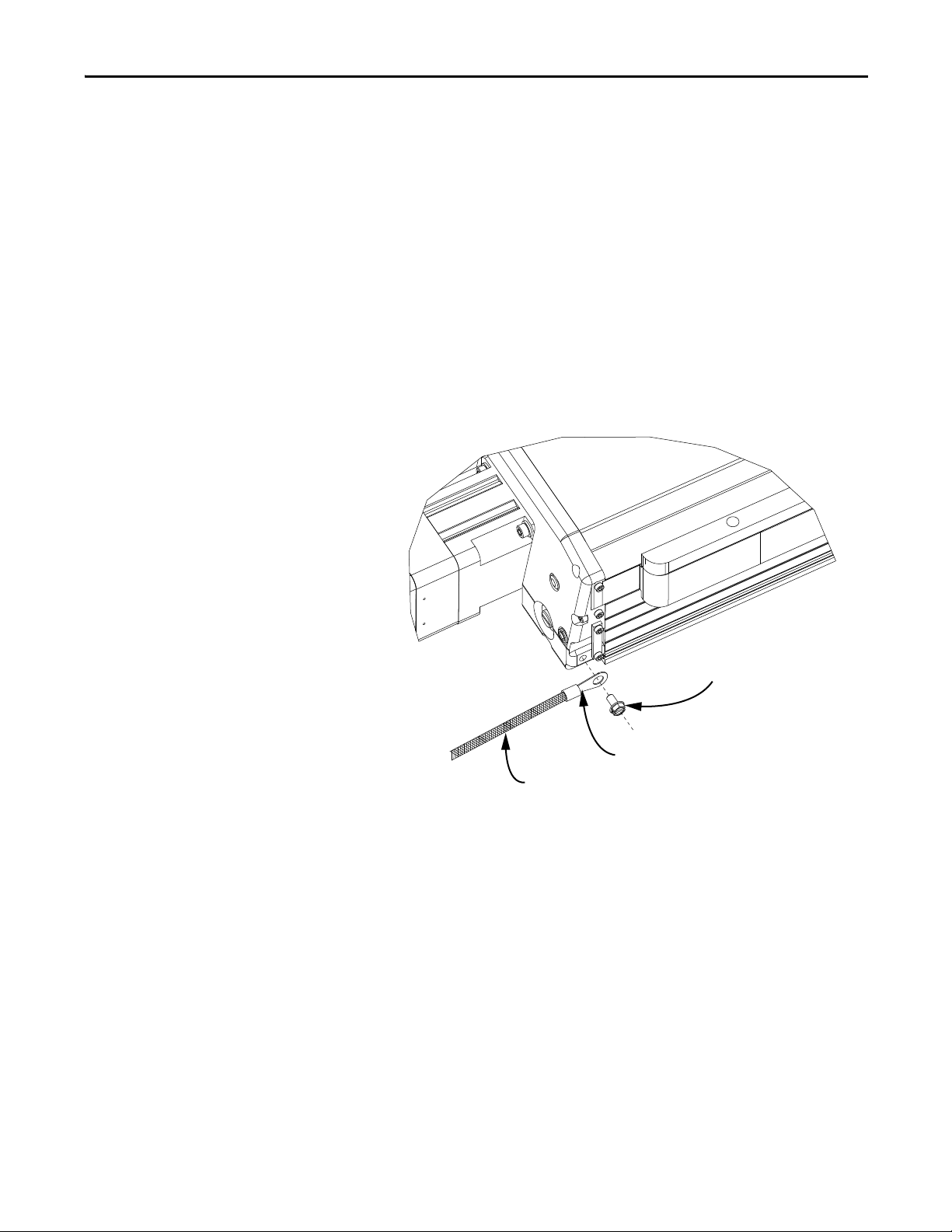
Attach the Ground Strap and Interface Cables
A ground strap and two cable connections are the only electrical connections
necessary between the linear stage and the drive system. The flat surfaces on the
power and feedback connectors must align during connection, and significant
resistance must not be felt when tightening either connector.
1. For electrical safety, connect the ground screw on the chassis of the linear
stage to the groundbus for your system.
To reduce the effects of electromagnetic interference (EMI), bond the
stage with a braided ground strap, 12 mm (0.5 in.) wide minimum, to a
grounded metal surface. This creates a low-impedance return path for
high-frequency energy.
2. Torque the ground screw at the linear stage to 2 N•m (18 lb•in.).
Rockwell Automation Publication MP-UM001D-EN-P - September 2013 35
Page 36
Chapter 4 Mounting and Connecting
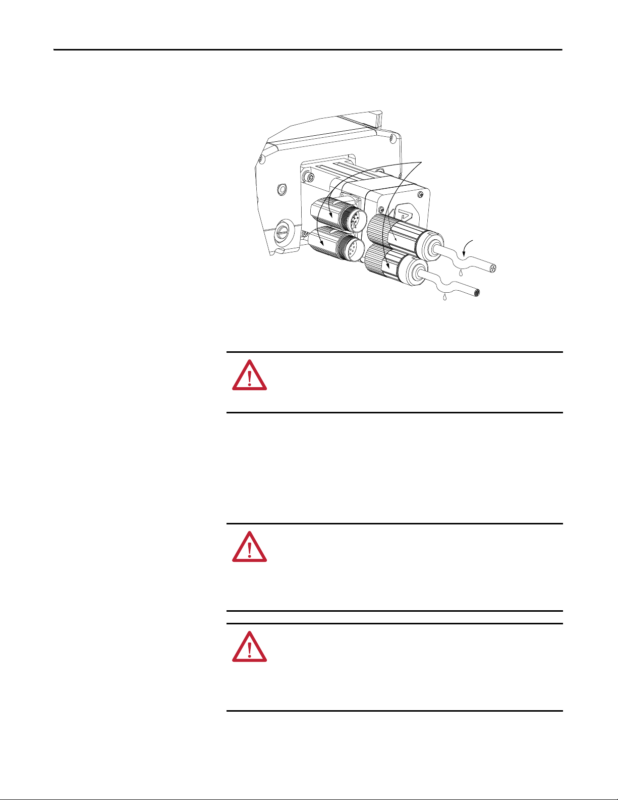
Align Flat Surfaces
Power/Brake
Connector
Feedback
Connector
Drip Loop
in Cable
3. Form a drip loop in each cable at a point directly before it attaches to the
motor.
4. Attach the feedback cable, and the combination power and brake cable to
the motor.
ATT EN TI ON : Do not connect or disconnect the motor feedback cable, or the
power and brake cable while power is applied to them.
Inadvertent pin connections can result in unexpected motion or result in
irreversible damage to the components.
a. Carefully align each cable connector with the respective motor
connector as shown in the diagram.
b. Do not apply excessive force when mating the cable and motor
connectors.
If the connectors do not go together with light hand force, realign and
try again.
ATT EN TI ON : Be sure that cables are installed and restrained to prevent uneven
tension or flexing at the cable connectors. Excessive and uneven lateral force at
the cable connectors can result in the connector’s environmental seal opening
and closing as the cable flexes.
Failure to observe these safety procedures could result in damage to the motor
and its components.
ATT EN TI ON : When installing a threaded DIN cable with a M4 designation, an
O-ring must be installed in the groove immediately adjacent to the body of the
linear thruster connector. This O-ring dampens the effects of vibration at the
cable-to-linear thruster connection.
Cables requiring O-rings include 2090-XXNFMF-Sxx (standard, non-flex)
feedback cables.
36 Rockwell Automation Publication MP-UM001D-EN-P - September 2013
Page 37
Mounting and Connecting Chapter 4
c. Fully seat the feedback connector and the power/brake connector.
• Hand tighten the collar of a threaded DIN (M4) connector six turns.
• Hand tighten the collar of a SpeedTec (M7) connector one-quarter turn.
ATT EN TI ON : Keyed connectors must be properly aligned and hand-tightened.
Improper alignment is indicated by the need for excessive force, such as the use of
tools, to fully seat connectors.
Connectors must be fully tightened for connector seals to be effective.
Failure to observe these safety procedures could result in damage to the motor,
cables, and connector components.
About the Air Option for Ball Screw Linear Stages
About the Brake Option for Ball Screw Linear Stages
A ball screw linear stage can connect to an external air supply via the air port,
item 21
on page 20. This can reduce the ingress of particulates in a dusty
environment.
• Air supplied to the ball screw stage must not exceed 270 kPa (40 psi).
• Plastic air tubing must be 6 mm (0.2362 in.) OD Teflon FEP tubing.
The brakes offered as options on the ball screw linear stages are holding brakes.
They are designed to hold the carriage in place up to the rated brake holding force.
The brakes release when voltage is applied to the brake coil. Voltage and polarity
supplied to the brake must be as specified to be sure of proper brake performance.
The brakes are not designed to stop the movement of a linear stage. Use the servo
drive inputs to stop motion. The recommended method of stopping motion is to
command the servo drive to decelerate to 0 mm/s (0 in/s), and engage the brake
after the servo drive has decelerated the linear stage to 0 mm/s (0 in/s).
If system main power fails, the brakes can withstand use as stopping brakes.
However, use of the brakes as stopping brakes creates rotational mechanical
backlash that is potentially damaging to the system, increases brake pad wear, and
reduces brake life. The brakes are not designed nor are they intended to be used
as a safety device.
Table 2 - Brake Specifications for Ball Screw Linear Stage Motors
Brake Response Time
Backlash
(brake engaged) Holding Force
Motor Cat. No.
MPAS-xxxxxx-V05xA 100 (0.004) 5187 (1166) 0.46…0.56 50 20 42
MPAS-xxxxxx-V20xA 1294 (291)
μm (in.) N (lb) A ms ms ms
Rockwell Automation Publication MP-UM001D-EN-P - September 2013 37
Coil Current
(at 24V DC)
Release
Engage Suppression via
MOV
Engage Suppression via
Diode
Page 38

Chapter 4 Mounting and Connecting
Meeting UL Installation Standards for the Linear Stage
Linear stage installations must follow UL 1740 - Standard for Safety for Robots
and Robotic Equipment.
Refer to UL Safety Standards for Linear Stage Installations
on page 24 for a brief
description of this standard.
ATT EN TI ON : UL 1740 requires all linear stage installations be equipped as
described below.
The design, operation, and verification of this implementation is the machine
builders responsibility.
A Power Enable light illuminates when drive power is applied and motion is
possible.
Emergency movement must be possible when drive power is not available to a
ball screw linear drive with a brake. See Figure 11 for an operator-controlled
circuit for a Kinetix 6000 drive that applies emergency power to release the brake.
Figure 11 - Emergency Brake Release for Ball Screw Linear Stage Example
Motor Brake
Motor Cable
2090-xxnpmf
Brake Release
Blk
Wht
Emergency
Switch
Dpdt
Emergency
Brake
Power
Supply
Rtn 24vRtn24v
Brake
Power
Supply
MBRK-
MBRK+
COM
PWR
DBRK-
DBRK+
Kinetix 6000
Brake Connector
6
5
4
3
2
1
38 Rockwell Automation Publication MP-UM001D-EN-P - September 2013
Page 39

Connector Data
A
CB
D
E
H
L
F
Intercontec P/N BKUA145NN00480200000
Mating Allen-Bradley Power Cable
2090-CPWM7DF-16AAxx (standard) or
2090-CPWM7DF-16AFxx (continuous-flex) or
2090-CPBM7DF-16AAxx (with brake)
Top ic Pag e
Linear Stage Power and Feedback Connections 39
PTC Thermal Signal 42
Chapter 5
Linear Stage Power and Feedback Connections
The following tables identify the power and feedback pinouts for circular
connectors for used with standard Allen-Bradley cables.
The direct drive and ball screw linear stages use different encoder types.
Consequently, the feedback connector signals are different for each of these
linear stage types.
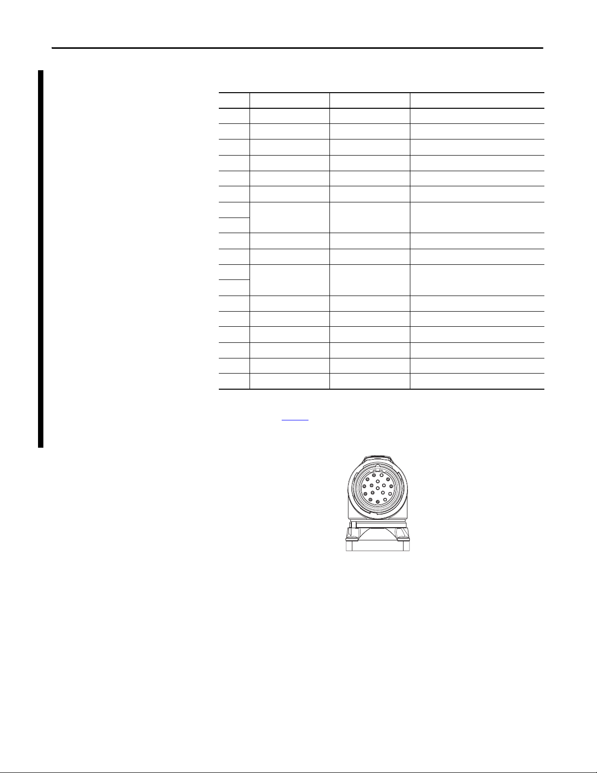
Table 3 - Power Connector
Pin Color
ARed U (A) Phase
B White V (B) Phase
CBlack W (C) Phase
D Green/Yellow Ground
F
White Brake+
G Black Brake-
(1) These are the wire colors for the leads on the direct drive linear stages (catalog number MPAS-xxxxxx-ALMx2C).
Wires for th e ball screw li near stages ( catalog numbe r MPAS-xxxxx x-V0xxSxA) are not field accessible.
(2) Brake+ and Brake- are available on only the ball screw linear stages having a rotary motor with a brake.
(1)
Signal
(2)
(2)
ATT EN TI ON : Disconnect input power supply before installing or servicing
stage.
Properly ground the stage as described in both this manual and the drive
manual
Rockwell Automation Publication MP-UM001D-EN-P - September 2013 39
Page 40
Chapter 5 Connector Data
Intercontec P/N AKU034NN004200000
Mating Cable Allen-Bradley Incremental Encoder Cable
2090-XXNFMF-Sxx (standard) flying leads or
2090-CFBM7DF-CDAFxx (continuous-flex) flying leads
1
2
3
4
5
6
7
8
9
10
11
12
13
14
15
16
17
Table 4 - Feedback Connector for Direct Drive Linear Stage
Pin Signal Name Wire Color
(2)
Signal Description
1 AM+ Yellow A Quad B TTL - A Differential
2 AM- White/yellow A Quad B TTL - A Differential
3 BM+ Brown A Quad B TTL - B Differential
4 BM- White/Brown A Quad B TTL -B Differential
5 IM+ Violet TTL - Index Mark Differential
6 IM- White/Violet TTL - Index Mark Differential
7 Reserved — —
8
9 +5V DC White/Red Encoder and Hall Sensor Power
10 Common Black Common
11 Reserved — —
12
13
PTC Temp+
(1)
Green
PTC Thermistor
14 Common White/Black Common
15 S1 White/Green TTL - Trapezoidal Hall Commutation
16 S2 Blue TTL - Trapezoidal Hall Commutation
17 S3 White/Blue TTL - Trapezoidal Hall Commutation
Case Shield — —
(1) PTC Temp- is connected to Common.
(2) These are the wire colors for the leads on the direct drive linear stages (catalog number MPAS-xxxxxx-ALMx2C).
Refer to Appendix B, Accessories
, for wire colors of interconnect cables.
40 Rockwell Automation Publication MP-UM001D-EN-P - September 2013
Page 41

Table 5 - Feedback Connector for Ball Screw Linear Stage
1
2
3
4
5
6
7
8
9
10
11
12
13
14
15
16
17
Intercontec P/N AEDC113NN00000222000
Mating Cable Allen-Bradley High Resolution Encoder Cable
2090-CFBM7DF-CEAAxx (standard) flying leads or
2090-CFBM7DD-CEAAxx (standard) D-sub or
2090-CFBM7DF-CEAFxx (continuous-flex) flying leads or
2090-CFBM7DD-CEAFxx (continuous-flex) D-sub
Connector Data Chapter 5
Pin Signal Name MPAS-
Axxxxx (230V)
Signal Description Signal Name MPAS-
Bxxxxx (460V)
1 S in+ Analog Differential 1V p-p Sin+
2 Sin- Analog Differential 1V p-p Sin-
3 Cos+ Analog Differential 1V p-p Cos+
4 Cos- Analog Differential 1V p-p Data-
5 Data+ Serial Data Differential Signal + Data+
6 Data- Serial Data Differential Signal - Data-
7 Reserved — Reserved
8
9 +5V DC 230V MPAS Encoder Power
10 Common 230V MPAS Encoder Common
11 Reserved 460V MPAS Encoder Power +9V DC
12 460V MPAS Encoder Common Common
13 TS+ PTC Thermistor TS+
14 TS- Common TS-
15 Reserved — Reserved
16
17
Case Shield — Shield
Rockwell Automation Publication MP-UM001D-EN-P - September 2013 41
Page 42

Chapter 5 Connector Data
PTC Thermal Signal
Temperature °C (°F) Resistance in Ohms
Up to 100 (212) ≤ 750
Up to 105 (221) ≤ 7500
Up to 110 (230) ≥ 10,000
(1) Measure thermistor resistance in a direct drive linear stage at pins 13 and 14 on the feedback
connector; see Feedback Connector for Direct Drive Linear Stage on page 40
(1)
for more information.
42 Rockwell Automation Publication MP-UM001D-EN-P - September 2013
Page 43

Configuration Guidelines
IMPORTANT
Top ic Pa ge
Required Files 43
Configuring Your Linear Stage 43
Configuring Ultraware Software for Linear Stages with Ultra3000 Drives 53
Setting Travel Limits 55
Home to Torque Programming for Kinetix Multi-axis Drives with Linear Stages 56
Chapter 6
Required Files
Configuring Your Linear Stage
Firmware revisions and software versions required to support the linear stages
include the following:
• RSLogix 5000 software, version 16.xx or the Logix Designer application
• Kinetix 2000 or Kinetix 6000 multi-axis drives
– Firmware revision 1.96 or later
– Motion Database file, version 4.6 or later
• Ultra3000 drives
– Firmware revision 1.52 or later
– Motion Database (.mdb) file, dated July 2007 or later
• Motion Analyzer software, version 4.4 or later
Download these files from
Rockwell Automation Technical Support at (440) 646-5800 for assistance.
Configure the linear stage by using the parameter settings described in this
chapter.
You are responsible for verifying that the servo control system safely controls
the linear stage with regard to maximum force, acceleration, and speed.
http://www.rockwellautomation.com/support/. Contact
ATT EN TI ON : Moving parts can injure. Before running the stage, make sure all
components are secure.
Check that the linear stage is clear of foreign matter and tools. Objects hit by the
moving stage can cause personnel injury or damage to the equipment.
Incorrect motor, Hall, or encoder wiring can cause uncontrolled motion.
Rockwell Automation Publication MP-UM001D-EN-P - September 2013 43
Page 44

Chapter 6 Configuration Guidelines
IMPORTANT
The type of Allen-Bradley drive connected to the linear stage determines the
configuration procedure. Refer to the following table to determine the
configuration procedures to follow.
If your servo drive is Start on page Continue with page
Kinetix 2000 (2093-xxxx-xxx) 41 51
Kinetix 6000 (2094-xxxx-xxx-x) 41
Ultra3000 SERCOS (2098-DSD-xxxx-SE) 41 N/A
Ultra3000 non-SERCOS (2098-DSD-xxxx) 49
If you are using a Kinetix 2000 or Kinetix 6000 drive, read and apply
Appendix E, Home to Torque-level Example
, to your system-level program.
This appendix provides information on using torque-level homing to reference
a known (home) position by monitoring torque while driving an axis into a
mechanical hard-stop.
44 Rockwell Automation Publication MP-UM001D-EN-P - September 2013
Page 45

Configuration Guidelines Chapter 6
Configuring the Logix Designer Application for Linear Stages with Kinetix Multi-axis Drives
The Logix Designer application parameters provide basic setup and tuning data
for MP-Series Integrated Linear Stages.
• Setting Axis Properties in the Logix Designer Application
provides basic
drive parameters for a linear stage in a table specific to the type of linear
stage, either direct drive linear or a ball screw.
• Tuning Linear Stages by Using the Logix Designer Application
begins on
page 44. It provides sections that describe how to complete these tasks:
– Tune Your Linear Stage
– Calculate and Configure the Loop Gain
– Setting Travel Limits
– only ball screw stages
– only ball screw stages
- both direct drive and ball screw stages
Setting Axis Properties in the Logix Designer Application
Use these parameter settings when configuring the ControlLogix drive system for
your linear stage. Parameter settings differ between the direct drive and ball screw
linear stages.
ATT EN TI ON : Incorrect parameter settings can result in uncontrolled motion,
with the potential for damage to the stage and machine.
Do not set the Positioning mode to Rotary for any linear stage. This results in
incorrect positioning of the linear stage.
Initiating a motion command on a stage with an incorrect Position mode setting
can result in damage to the stage and the machine.
The following steps assume the MP-Series linear stage and a Kinetix 2000 or
Kinetix 6000 servo drive are installed and wired as one axis of a motion system.
Direct Drive Linear Stages
Set these parameters in the appropriate Axis Properties tab of the Logix Designer
application for direct drive linear stages, catalog number MPAS-xxxxxx-
ALMx2C.
Axis Properties Tab Parameter Entry/Selection, with applicable distance unit settings
Millimeters Inches
Drive/Motor Motor Catalog Number Select one from the list
MPAS-A6xxxB-ALMO2C
MPAS-A6xxxB-ALMS2C
MPAS-A8xxxE-ALMO2C
MPAS-A8xxxE-ALMS2C
MPAS-A9xxxK-ALMO2 C
MPAS-A9xxxK-ALMS2 C
MPAS-B8xxxF-ALMO2C
MPAS-B8xxxF-ALMS2C
MPAS-B9xxxL-AL MO2 C
MPAS-B9xxxL-AL MS2 C
Drive Resolution 200
Drive Counts per Motor Millimeter
Rockwell Automation Publication MP-UM001D-EN-P - September 2013 45
Page 46

Chapter 6 Configuration Guidelines
(+)
(-)
(+)
(-)
Axis Properties Tab Parameter Entry/Selection, with applicable distance unit settings
Millimeters Inches
Motor Feedback Feedback Type TTL with Hall
Cycles 50
Per Millimeter
Conversion Positioning Mode Linear
Conversion Constant 200 drive counts / 1.0 mm 5080 drive counts / 1.0 in.
(1)
Hookup
Test Increment 70 mm, min for Ultra3000 drive
20 mm Kinetix 2000 drive
20 mm Kinetix 6000 drive
2.76 in. min for Ultra3000 drive
0.787 in. Kinetix 2000 drive
0.787 in. Kinetix 6000 drive
Drive Polarity Positive (see definition)
Homing Mode Active
Position 0 (or programmable)
Offset 5 mm, min 0.2 in., min
Sequence Torque Level-to-Marker
Direction Reverse Bi-directional
Torque Level 80%, min
Greater if the system friction, force, or weight exceeds 80% of the Continuous Force Rating at any point in the range
of motion
Speed 50 mm/s 1.97in/s
Return Speed 10 mm/s 0.39 in/s
Soft ware or Hardware L imits Neg ative Limit
Use Motion Analyzer to determine the maximum stopping distance in your application
or
Positive Limit
(1) The Command and Feedback test, accessed from the Hookup tab, does not verify the Hall Sensor wiring to a Kinetix 2000 or a Kinetix 6000 drive. The wire colors and continuity for the Hall signals must be
manually verified.
46 Rockwell Automation Publication MP-UM001D-EN-P - September 2013
Page 47

Ball Screw Drive Stages
(+)
(-)
Set these parameters in the appropriate Axis Properties tab of the Logix Designer
application for ball screw linear stages, catalog number MPAS-xxxxxx-VxxxxA.
Axis Properties Tab Parameter Entry/Selection, with applicable distance unit settings
Millimeters Inches
Drive/Motor Motor Catalog Number Select one from the list
MPAS-Axxxx1-V05S2A
MPAS-Axxxx1-V05S4A
MPAS-Axxxx2-V20S2A
MPAS-Axxxx2-V20S4A
MPAS-Bxxxx1-V05S2A
MPAS-Bxxxx1-V05S4A
MPAS-Bxxxx2-V20S2A
MPAS-Bxxxx2-V20S4A
Drive Resolution 200,000
Drive Counts per Motor Millimeter
Conversion Positioning Mode Linear
ATTENTION: Setting the Positioning Mode to Rotary can cause damage to the stage or
the machine due to incorrect positioning.
Configuration Guidelines Chapter 6
Conversion Constant 40,000 drive counts / 1.0 mm for 1,016,000 drive counts / 1.0 in. for
MPAS-Axxxx1-V05S2A
MPAS-Axxxx1-V05S4A
MPAS-Bxxxx1-V05S2A
MPAS-Bxxxx1-V05S4A
Conversion Constant 10,000 drive counts / 1.0 mm for 254,000 drive counts / 1.0 in. for
MPAS-Axxxx2-V20S2A
MPAS-Axxxx2-V20S4A
MPAS-Bxxxx2-V20S2A
MPAS-Bxxxx2-V20S4A
Hookup Test Increment 5 mm min 0.2 in., min
Drive Polarity Positive (see definition)
Rockwell Automation Publication MP-UM001D-EN-P - September 2013 47
Page 48

Chapter 6 Configuration Guidelines
IMPORTANT
IMPORTANT
TIP
Axis Properties Tab Parameter Entry/Selection, with applicable distance unit settings
Millimeters Inches
Homing Mode Active
Position 0 (or programmable)
Offset 5 mm, min 0.2 in., min
Sequence Torque Level-to-marker
Direction Reverse Bi-directional
Torque Level 50%, min
Speed 50 mm/s 1.97in./s
Return Speed 10 mm/s 0.39 in./s
Absolute Home is available for ball screw linear stages. For maximum range of motion, position the carriage so its proximal edge is 25.4 mm (1.0 in.)
from the inside edge of the end plate.
Soft ware or Hardware L imits Neg ative Limit
or
Positive Limit
Greater if the system friction, force, or weight exceeds 50% of the Continuous Force Rating at any point in the range
of motion.
Use Motion Analyzer to determine maximum stopping distance in your application
Tuning Linear Stages by Using the Logix Designer Application
This section documents the steps necessary to tune linear stages by using the
RSLogix 5000 software, version 16.xx or the Logix Designer application.
ATTENTION: The Tuning and Loop Gain procedures apply to only the ball
screw linear stages.
The Travel Limit procedures apply to both the direct drive and the ball screw
linear stages.
• Tuning your linear stage requires you to calculate and configure the loop
gain based on the actual measured inertia.
• Setting travel limits defines the minimum deceleration for your specific
application.
Tune Your Linear Stage
These procedures apply to only ball screw linear stages.
Set the following parameters in the Axis Properties tab of the Logix Designer
application to tune a ball screw drive linear stage (catalog number MPAS-xxxxxx-
VxxSxA).
1. In the Axis Properties dialog box, click Fault Actions >
Set Custom Stop Action > Custom Stop Attributes.
These parameter settings work best if the linear stage is installed in a
horizontal (table top) or a wall mount (vertical) orientation.
48 Rockwell Automation Publication MP-UM001D-EN-P - September 2013
Page 49
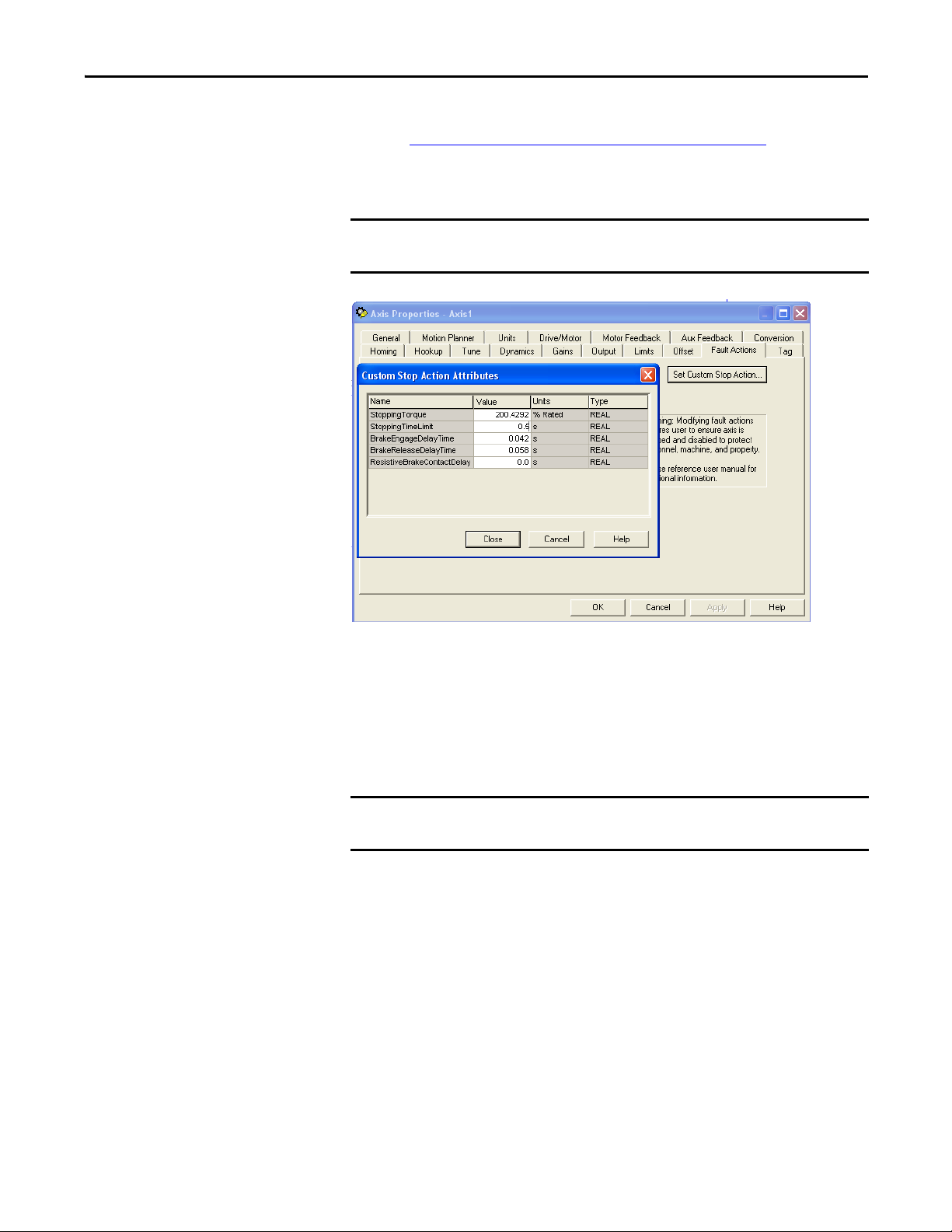
Configuration Guidelines Chapter 6
IMPORTANT
IMPORTANT
2. Set the Brake Engage and the Brake Release delay times to the values listed
in Brake Specifications for Ball Screw Linear Stage Motors
on page 89.
3. Reduce the default Stopping Time Limit from 10 seconds to 0.5 seconds,
as shown in the following display.
To prevent the carriage from moving, or falling when installed in a vertical
orientation, the Stopping Time Limit must be set to 0.99 seconds or less.
4. Select the Tune tab in the Axis Properties dialog box and enter the
following parameters.
a. Set the Travel Limit to no more than the travel length of the linear
stage.
b. Configure the appropriate Speed (velocity).
c. Configure the appropriate Torque/Force.
Check only Torque Offset, as shown below, if the linear stage is installed in a
non-horizontal mount position.
Rockwell Automation Publication MP-UM001D-EN-P - September 2013 49
Page 50
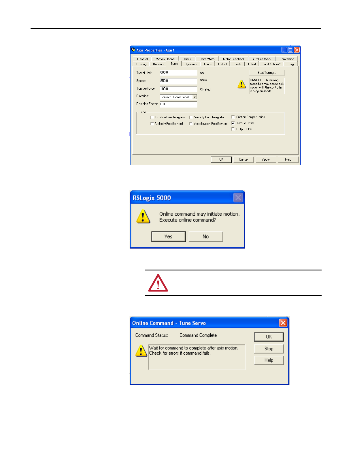
Chapter 6 Configuration Guidelines
5. On the Tune tab, click Start Tuning to access the Motion Initiation dialog
box.
6. Click Yes to begin tuning the linear stage.
ATTENTION: Motion occurs immediately after clicking Yes
Tun ing is c omp le te whe n th e Tun e S er vo dia lo g bo x ap pe ar s.
7. Select Yes to exit Tuning, and display the Tune Results dialog box.
50 Rockwell Automation Publication MP-UM001D-EN-P - September 2013
Page 51

Configuration Guidelines Chapter 6
IMPORTANT
Calculate and Configure the Loop Gain
These Loop Gain procedures apply to only ball screw linear stages.
You must calculate a position loop bandwidth based on the actual measured
inertia. This is done by using the values from the Tune Results dialog box for a
ball screw drive linear stage.
The Tune Results dialog box above shows a default Position Loop Bandwidth of
45.14153 Hz, and a Load Inertia Ratio of 6.8707952.
1. Calculate the Corrected Position Bandwidth as follows:
Corrected Position Loop Bandwidth = (Initial Position Loop Bandwidth
Result/(Initial Load Inertia Ratio Result +1)
For example, 5.73532 = 45.14153 / 7.8707952.
2. Enter the Corrected Position Bandwidth value 5.73532 as the Position
Loop Bandwidth and click OK.
Rockwell Automation Publication MP-UM001D-EN-P - September 2013 51
Page 52
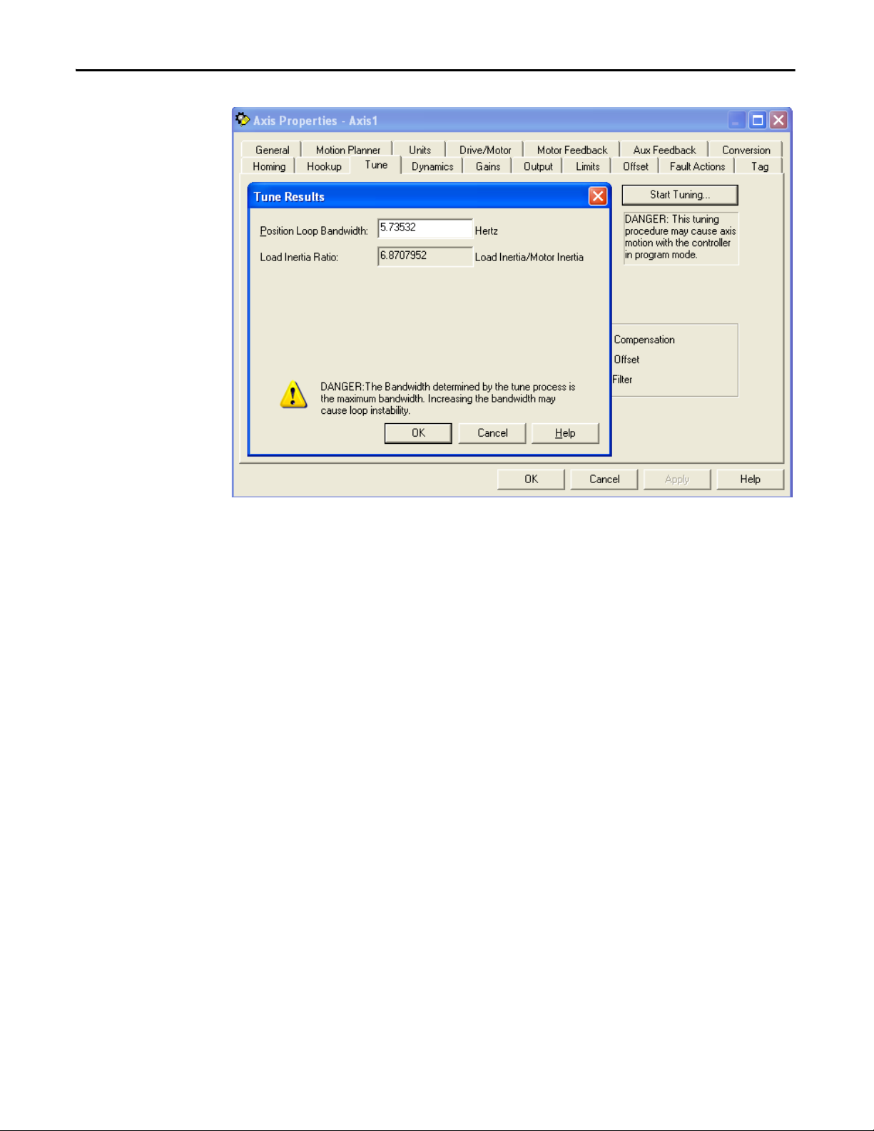
Chapter 6 Configuration Guidelines
3. Answer the remaining dialog boxes to apply the values.
The proper Position Bandwidth results in a stable starting point from that you
can adjust the gains to fit the application requirements.
52 Rockwell Automation Publication MP-UM001D-EN-P - September 2013
Page 53

Configuration Guidelines Chapter 6
Configuring Ultraware Software for Linear Stages with Ultra3000 Drives
The following steps assume that the MP-Series linear stage and an Ultra3000
servo drive are installed and wired as one axis of a motion system.
1. Connect a serial cable model, catalog number 2090-DAPC-D09xx, to the
CN3 connector on your Ultra3000 servo drive.
2. Apply ac input power to the Ultra3000 drive.
3. Establish communication with the Ultra3000 drive, and click Cancel
when the Ultra3000 motor database dialog box appears.
Clicking Cancel causes the Ultraware software to scan for online drives.
When a drive is found, an Online Drive icon displays in the Workspace.
4. Double-click the Online Drive icon to view the main Drive setup dialog
box.
5. Perform the action in the following table appropriate for your type of
linear stage.
If your linear stage is a Do this
Direct drive
MPAS-xxxxxx-ALMO2C
Ball Screw
MPAS-xxxxx-V05S2A, or MPAS-xxxxx-
V20S2A
Select your direct drive linear stage from the drop down in the
Motor Model dialog box, and then verify the data in the Motor
Field is correct for your direct drive linear stage.
Verify the data in the Model Field is correct for your ball screw
linear stage.
Auto Motor Iden (identification) is enabled for only ball screw linear stages.
Auto Motor Iden remotely identifies the motor, and then populates the
model field with the appropriate motor information. Direct drive linear
stages do not interact with Auto Motor Iden, and the model field data must
be manually selected for the appropriate motor information to load.
6. From the Displayed Units pull-down menu, choose User.
This programs Ultraware software to make distance moves in User Units
(mm or in.).
7. In the Motor Encoder Units pull-down menu, enter the appropriate values
from the following tables.
Velocity, position, and acceleration counts per unit are based on the
selected User Units (mm or in.).
Rockwell Automation Publication MP-UM001D-EN-P - September 2013 53
Page 54
Chapter 6 Configuration Guidelines
Table 6 - Scaling Parameters Values
User Unit Scaling Parameters
(1)
Distance Units for Ball Screw Linear Stages
Millimeters Inches
MPAS-xxxxxx-V05xxA MPAS-xxxxxx-V20xxAMPAS-xxxxxx-V05xxA MPAS-xxxxxx-V20xxA
Velocity Label mm/s mm/s in./s in./s
Velocity Scale 26214.4 6553.6 665845.76 166461.44
Position Label mm mm in. in.
Position Scale 26214.4 6553.6 665845.76 166461.44
Acceleration Label mm/s/s mm/s/s in./s/s in./s/s
Acceleration Scale 26214.4 6553.6 665845.76 166461.44
(1) User units are determined by the screw lead of the linear stage. The screw lead is defined in linear units of travel per revolution. For example, the travel per revolution of an MPAS-xxxxxx-V05xxA is 5 mm/
rev and that of an MPAS-xxxxxx-V20xxA is 20 mm/rev. MP-Series linear stages with a ball screw use a feedback device that provides 128 sin/cos cycles per revolution of the motor. The Ultra3000 drive
interpolates this signal by an additional 1024, causing the ma ximum count per internal motor revolution of the linear stage to be 131,072 counts/rev.
Table 7 - Direct Drive Linear Stage Distance Unit Settings
User Unit Scaling Parameters Distance Units
Millimeters Inches
Velocity Label mm/s in./s
Velocity Scale 200 5080
Position Label mm in.
Position Scale 200 5080
Acceleration Label mm/s/s in./s/s
Acceleration Scale 200 5080
54 Rockwell Automation Publication MP-UM001D-EN-P - September 2013
Page 55
Configuration Guidelines Chapter 6
IMPORTANT
J
1
2
---
M× V2×=
Setting Travel Limits
MP-Series Integrated Linear Stages are designed to use the software overtravel
limits available in the Logix Designer application and Ultraware software.
These Travel Limit procedures apply to both direct drive or ball screw linear
stages.
Overtravel limits must be set according to the maximum speed of the servo drive
system and the payload of the application. The Deceleration Distance before the
slide contacts the end-of-travel bumpers can be determined based on the
Deceleration Rate of the load, and the available peak force from the stage-drive
combination. Then use Motion Analyzer software to calculate the minimum
deceleration distance at the maximum speed of your application.
(1)
Software overtravel limits are preferred for these reasons.
• Hard-wired overtravel limit switches are typically in a position that does
not let the linear stage decelerate before mechanical damage occurs.
• Software overtravel limit switches can be precisely set, based on maximum
speed and load inertia. The stage comes to a complete stop before physical
damage occurs.
In addition to software overtravel limits, the end of travel bumpers for the linear
stage stops the carriage up to the ratings listed in the table.
Table 8 - Bumper Stop Energy Limits for Linear Stage End of Travel
Catalog Number Energy Limit Catalog Number Energy Limit Catalog Number Energy Limit
MPAS-x6xxx1-V05xxA 37.3 J (330 in-lb) MPAS-x8xxx1-V05xxA 22.7 J (201 lb-in) MPAS-x9xxx1-V05xxA 16.5 J (146 lb-in)
MPAS-x6xxx1-V20xxA MPAS-x8xxx1-V20xxA MPAS-x9xxx1-V20xxA
MPAS-x6xxx1-ALMx2C MPAS-x8xxx1-ALMx2C 45.5 J (403 lb-in) MPAS-x9xxx1-ALMx2C 35.2 J (312 lb-in)
ATT EN TI ON : If energy greater than the bumper capacity is anticipated in the
application, you must provide additional mechanical means for safely stopping
the carriage.
To calculate kinetic energy of the carriage with your payload use the formula
J = energy in Joules
M = moving mass (linear carriage + payload) [kg]
V = maximum velocity of stage in your application [m/s] (1
)
(1) Velocity and kinetic energy can be much higher due to uncontrolled, worst-case motion that is constrained by the length of stroke
and the power capacity of the motor-drive pairing.
Rockwell Automation Publication MP-UM001D-EN-P - September 2013 55
Page 56

Chapter 6 Configuration Guidelines
IMPORTANT
Home to Torque Programming for Kinetix Multi-axis Drives with Linear Stages
If you are using a Kinetix 2000 or Kinetix 6000 drive, read and apply Appendix E,
Home to Torque-level Example
Perform Home to Torque Programming after you have tuned your drive and
linear stage combination.
Successfully complete tuning by performing the steps starting on page 43
This appendix provides information on using torque-level homing to reference a
known (home) position by monitoring torque while driving an axis into a
mechanical hard-stop.
, to your system-level program.
.
56 Rockwell Automation Publication MP-UM001D-EN-P - September 2013
Page 57

Maintenance
IMPORTANT
Topic Page
Before You Begin 57
Recommended Maintenance Intervals 57
Bearing Lubrication 58
Strip Seal Cleaning 59
Cover Cleaning 59
Any person that teaches, operates, maintains, or repairs these linear
stages must be trained and demonstrate the competence to safely
perform the assigned task.
Chapter 7
Before You Begin
Recommended Maintenance Intervals
Use the following tools to lubricate and clean your linear stage.
ATT EN TI ON : Lockout and tagout input power before servicing.
• 0.36 meter (14 inches) or larger clamp with soft jaws
• Grease pump kit (catalog number MPAS-GPUMP) with tip type installed
and primed
• Grease cartridge (catalog number MPAS-CART), included in grease
pump kit.
• Air line having a maximum pressure of 68 kPa (10 psi)
• Lint-free cloth
• Isopropyl alcohol, as necessary for cleaning
Recommended maintenance and lubrication intervals are:
• direct drive linear stages every 6 months or 5000 km of travel, whichever
comes first
• ball screw linear stages every 3 months or 150,000,000 revolutions,
whichever comes first
.
Rockwell Automation Publication MP-UM001D-EN-P - September 2013 57
Page 58

Chapter 7 Maintenance
Bearing Lubrication Ports (two per end cap)
Ball Nut Lubrication Port
(one per linear stage)
Bearing Lubrication
Lubricate the linear stage bearings as shown and described below. Use the MPSeries Integrated Linear Stage grease pump kit, and additional grease cartridges as
necessary.
Figure 12 - Direct Drive Linear Stage Lubrication
Bearing Lubrication Ports (two per end cap)
Figure 13 - Ball Screw Linear Stage Lubrication
58 Rockwell Automation Publication MP-UM001D-EN-P - September 2013
1. Position the carriage at end of travel and clamp it to hold the linear stage
against end block.
ATT EN TI ON : Do not use clamp across the side panels. This deforms and
damages the side panels.
2. Remove the lubrication port protective caps on each end cap.
3. Insert the tip of the grease pump into the lubrication port, pushing in until
firm contact with the grease fitting is made.
4. Pump the handle until back pressure is felt, or a maximum of two strokes
are made.
5. Repeat step 3 and step 4 to the other lubrication ports.
6. Move the carriage to opposite end of travel and repeat steps 1…5.
Page 59

7. Remove the clamp.
IMPORTANT
8. Reinstall the protective caps on all the lubrication ports.
Maintenance Chapter 7
Strip Seal Cleaning
Cover Cleaning
Clean the strip seals, if installed, by using a lint free cloth lightly saturated with
isopropyl alcohol.
Repl ace the stri p seal if it cannot be clean ed, or if an uneve n or scored surface is
detected during cleaning.
A buildup of foreign material on the strip seal degrades the performance of the
linear stage. This buildup coupled with rapid movement of the carrier and the
resulting friction scores the surface and create a burnished appearance on the
strip seal.
Elements contributing to a typical buildup on the strip seals are dust, grease,
and other contaminants normally encountered in any operating environment
that is not strictly controlled.
Refer to the Strip Seal Removal on page 63
page 64 when performing this task.
Clean the covers at the same time you clean the strip seals. Use pressurized air and
a lint free cloth lightly saturated with isopropyl alcohol to remove any dirt or
grease.
and Strip Seal Replacement on
Rockwell Automation Publication MP-UM001D-EN-P - September 2013 59
Page 60

Chapter 7 Maintenance
Notes:
60 Rockwell Automation Publication MP-UM001D-EN-P - September 2013
Page 61

Removing and Replacing Components
Top ic Pag e
Before You Begin 61
Cable Carrier Assembly Removal 62
Cable Carrier Assembly Installation 62
Strip Seal Removal 63
Cover Removal 64
Cover Insta llation 64
Strip Seal Replacement 64
Side Cover Installation 65
Rotary Motor Replacement 66
Chapter 8
Before You Begin
ATT EN TI ON : Lockout and tagout input power before servicing.
ATT EN TI ON : These procedures are not applicable to both types of linear stages.
Direct drive and ball screw linear stages have unique configurations
Assemble these tools before you begin removal and replacement procedures.
• 2.5 mm, 3 mm, 4 mm, 5 mm, and 6mm hex keys
• 0.8mm (0.03in) shim
• Fine-point permanent marker
• Ruler
• Tin snips
• Loctite 222
• Phillips and flat-blade screwdrivers
Rockwell Automation Publication MP-UM001D-EN-P - September 2013 61
Page 62

Chapter 8 Removing and Replacing Components
TIP
Junction Box Side Cover
Junction Box Cover
Cable Carrier Module
Angle Bracket
End Bracket
Feedback Connector
Motor Power Connector
M3 0.5 X8 LG
Phillips Pan Head Screws (4x)
M4 X 0.7 X 8 LG BHCS (2x)
M4 X 0.7 X 10
LG SHCS (2x)
M3 X 0.5 X 8
LG SHCS (2x)
Cable Carrier Assembly Removal
Follow these directions to remove the cable carrier assembly.
Mark the location of the end bracket before removing the cable carrier, this
makes it easier to align it when reinstalling.
1. Remove the four pan head screws from junction box side cover.
2. Remove the two button head cap screws (BHCS) from the junction box
cover.
3. Remove the junction box cover assembly.
Figure 14 - Cable Carrier Removal
Cable Carrier Assembly Installation
ATT EN TI ON :
Never pull on wires when disconnecting power and feedback
connectors. Damage to circuit continuity can occur.
4. Separate the motor power connector by squeezing the side tabs and pulling
on the housing, but do not pull on the wires.
5. Separate the feedback connector from the circuit board by pushing on the
center tab and pulling up on the connector housing, but do not pull on the
wires.
6. Remove the two SHCS from the cable carrier angle bracket.
7. Lay the cable carrier out flat and mark the location of the end bracket.
8. Loosen, but not remove, the two SHCS securing the end bracket to the
base of the linear stage.
9. Remove the cable carrier.
Follow the Cable Carrier Assembly Removal procedure in reverse.
62 Rockwell Automation Publication MP-UM001D-EN-P - September 2013
Page 63

Removing and Replacing Components Chapter 8
IMPORTANT
Stainless Steel
Strip Seal (2x)
Strip Seal Clamp (4x)
Seal Guide (4x)
M3 SHCS (2 per guide)
M3 SHCS (8x)
M4 SHCS (2 per side)
Align the cable carrier by using the alignment marks made when the worn cable
carrier was removed.
Strip Seal Removal
Follow these directions to remove a strip seal.
Figure 15 - Linear Stage Seal Components
Handle strip seal material with care. The strip seal has sharp edges that can cut
if mishandled.
1. Loosen the strip seal clamps at each end of the linear stage.
2. Carefully grasp the end of the strip seal and slide it out of the linear stage.
Cover Removal
Follow these directions to remove a side cover.
1. Remove strip seals following the strip seal removal procedure.
2. Remove the four M4 screws securing the linear stage cover to the end caps.
3. Remove the cover.
Rockwell Automation Publication MP-UM001D-EN-P - September 2013 63
Page 64
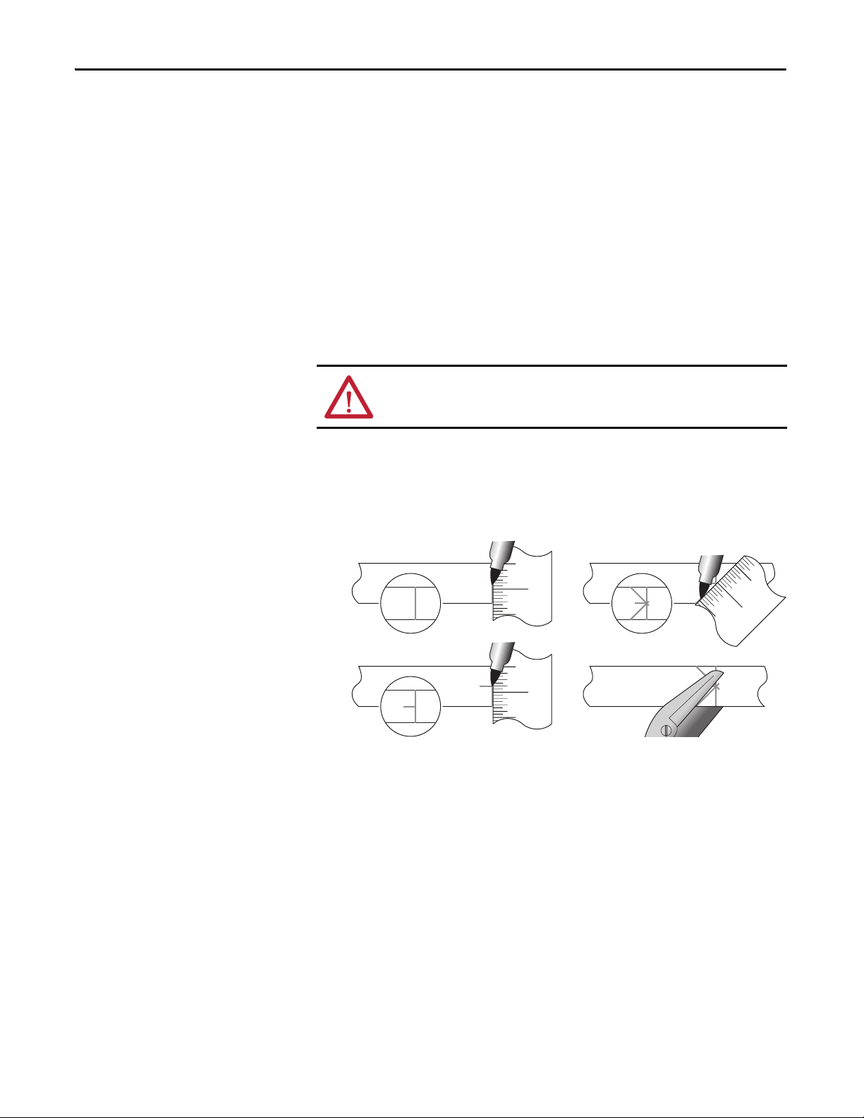
Chapter 8 Removing and Replacing Components
1) Mark needed strip length.
2) Mark strip width centerline.
3) Make two 45º marks to centerline.
4) Use tin snips to cut along 45º marks.
Cover Installation
Strip Seal Replacement
Follow these directions to install a cover.
1. Start at the end cap nearest the magnetic cautionary label or the MP
motor, and install two M4 x 25 SHCS.
2. Torque the M4 x 25 SCHS to 4 N•m (35 lb•in).
3. Make sure the cover contacts the end cap.
4. On the opposite end install two M4 x 30 SHCS and bottom out the screw.
The cover does not contact the end cap on this side and floats on the screw.
Follow these directions to replace the strip seals.
ATT EN TI ON : Handle strip seal material with care. The strip seal has sharp edges
that can cause personal injury if mishandled.
1. Remove power from the linear stage, and lock out and tag the power
source.
2. Follow the instructions below on how to measure, mark, and cut new strip
seals.
64 Rockwell Automation Publication MP-UM001D-EN-P - September 2013
3. Position the carriage at the midpoint of stage travel.
4. Expose the center metal section of the carriage’s seal strip guide by
loosening the screws securing the end clamps and those at the carriage seal
guide.
5. Thread the new strip seal, point end first, through the seal guides, the
carriage, and then the end clamps.
6. Center and smooth the strip seal against the top cover and the side panel
magnetic strips.
7. By using very light pressure, hold the seal guide against the strip seal, and
then tighten the seal guide.
8. Tighten one end clamp, but do not tighten the clamp on the other end.
Page 65

Removing and Replacing Components Chapter 8
Seal Guide
0.8 mm (0.03 in.) Shim
Strip Seal
TIP
9. Move the carriage by hand through the complete range of travel and make
sure the strip seal seats smoothly against the cover and side panel magnet
strips.
Pulling against the tightened end clamp helps to smooth the seal.
10. Once the seal lays flat and smooth against the top cover and side panel,
tighten the second end clamp.
11. With the outside edge of the end clamps as a guide, use tin snips to cut and
remove excess strip seal material.
12. Position the carriage at the far ends of travel.
13. Adjust the seal guide by inserting a 0.8 mm (0.03 in.) shim between the
seal guide and the strip seal.
Side Cover Installation
14. Return the linear stage to service.
Follow these directions to install a side cover.
1. Insert a side cover into the base of the linear stage by holding it with the
top slightly tilted outward and hooking the bottom of the side cover in the
channel near the bottom of the base.
If installing the side cover with strip seals in place use a flat-blade screwdriver
to lift the side cover by inserting the screwdriver under the cover between the
cover and the base.
2. Starting at the end cap adjacent to the ground screw, install one M4 SHCS
and torque it to 4 N•m (35 lb•in).
3. On the opposite end, install one M3 SHCS and torque it to 2.5 N•m
(20 lb•in).
Rockwell Automation Publication MP-UM001D-EN-P - September 2013 65
Page 66
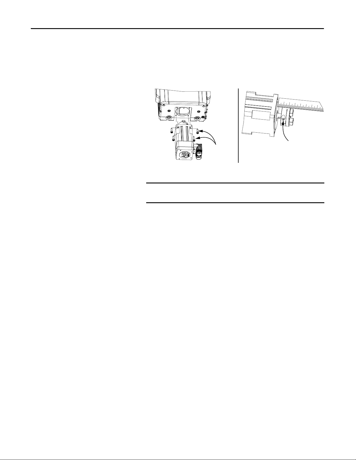
Chapter 8 Removing and Replacing Components
IMPORTANT
M5 SHCS (4x)
AB
M4 SHCS
Rotary Motor Replacement
Follow these directions to replace a rotary motor.
1. Disconnect the motor cables.
2. Remove the four M5 SHCS and lock washers that secure the motor to the
linear stage.
3. Remove the motor.
Measure the position of the coupling on the motor shaft as shown in
panel B of the diagram above.
4. Mark the measured coupling position on the new motor shaft.
5. Loosen the M4 SHCS in the coupling and remove the coupling from old
motor shaft.
6. Position the coupling on the new motor shaft, align it with the mark made
in step 4, and then tighten the coupling.
7. Align the coupling halves and install the motor.
8. Secure the motor with four M5 SHCS and lock washers.
9. Torque each cap screw to 4 N•m (35 lb•in), by using a diagonal tightening
sequence.
66 Rockwell Automation Publication MP-UM001D-EN-P - September 2013
Page 67
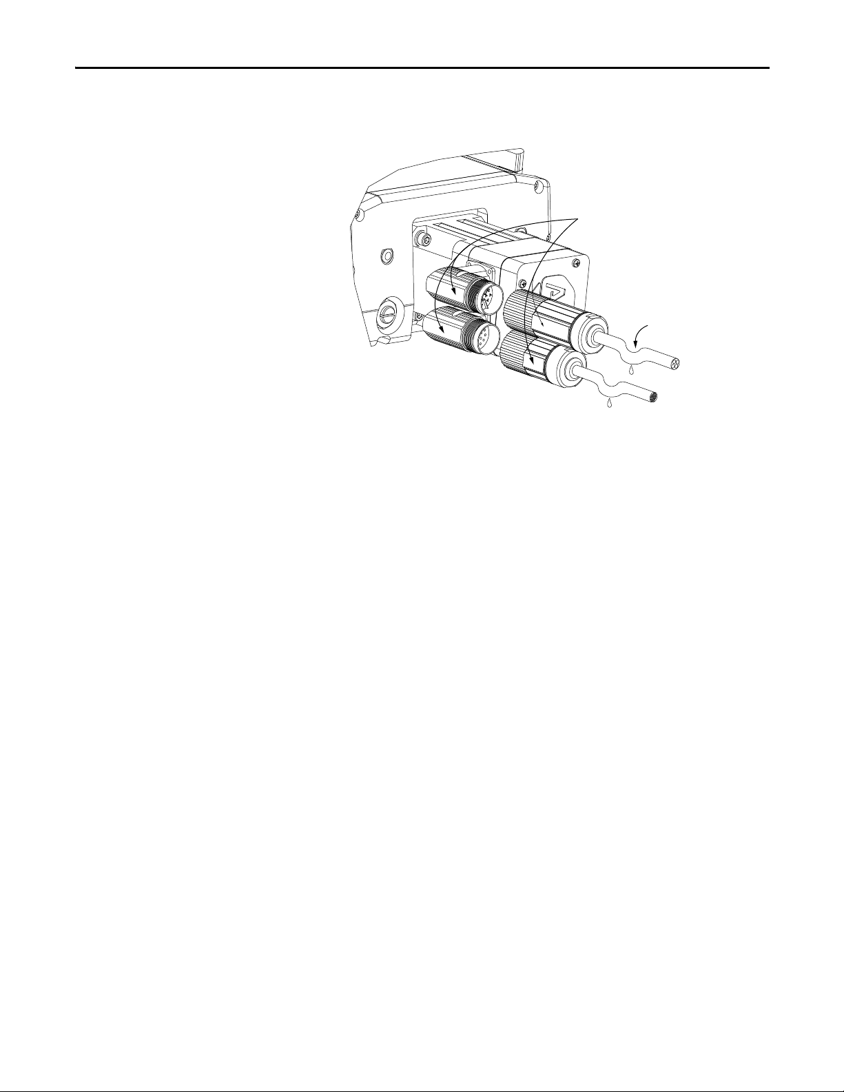
Removing and Replacing Components Chapter 8
Align Flat Surfaces
Power/Brake
Connector
Feedback
Connector
Drip Loop
in Cable
10. Attach the power and feedback cables to the motor, by aligning the flat
edges on the cable connector with those on the motor connector.
Rockwell Automation Publication MP-UM001D-EN-P - September 2013 67
Page 68

Chapter 8 Removing and Replacing Components
Notes:
68 Rockwell Automation Publication MP-UM001D-EN-P - September 2013
Page 69

Chapter 9
TIP
Troubleshooting
This chapter is divided into three sections:
• Use the diagnostic tables during axis commissioning
• Use the operational section to troubleshoot either a direct drive or ball
screw linear stage after the axis is up and running
• Use the thermistor measurement section when direct-drive operational
troubleshooting suggests
Top ic Pa ge
Troubleshooting During Commissioning and Start-up 69
Operational Troubleshooting 70
Troubleshooting During Commissioning and Start-up
Use this section to diagnose and correct troubles encountered while using Logix
Designer application to commission and start your linear stage.
Symptom Possible Cause Solution
Initialization stops at SERCOS Level 3
and Logix software reports Motor
Attribute Error.
Drive reporting error E04, E11, or E07. Incorrect feedback wiring. Verify feedback wiring. Refer
Incorrect motor catalog number. Enter correct motor catalog number.
Incorrect drive firmware. For Kinetix 6000 and Kinetix 2000
From using a previously defined axis. Delete and recreate the axis.
drives, verify the firmware revision is
1.96 or later,
For a Ultra3000 drive, verify the
firmware revision is 1.52 or later.
to Wiring Examples on page 87
.
In the Hookup tab of Axis Properties, click on the Test Command and Feedback
button to verify wiring and commissioning of your linear stage. The following
table lists possible solutions for problems encountered while performing this test.
Hookup testing can fail if friction and weight forces exceed 20% of the
stage’s continuous force rating.
Rockwell Automation Publication MP-UM001D-EN-P - September 2013 69
Page 70

Chapter 9 Troubleshooting
Symptom Possible Cause Solution
Linear stage, direct drive or ball
screw, passes Hookup testing but the
carriage jumps position when the
axis is enabled.
Direct drive linear stage fails Hookup
testing, but wiring is known to be
correct.
Wiring of the Hall signals with
relation to the motor’s power wiring
is incorrect.
Incorrect drive firmware. Verify the Kinetix 6000 drive or,
Verify wiring of Hall signals (S1, S2,
and S3) and power wires (U, V, and
W).
Kinetix 2000 drive has revision 1.96
or later firmware.
Verify you are using version 16.00 or
later of Logix software.
Operational Troubleshooting
Use this section to diagnose and correct troubles with a direct drive or ball screw
driven linear stage after it has been commissioned. Read the entire section to
understand the kinds of troubles you can encounter and the possible fixes.
The evaluation procedures for both the direct drive and ball screw linear stages
helps you determine if faulty stage operation simply indicates a need to lubricate
the stage or a more fundamental problem. To interpret error codes reported by
the drive, refer to Troubleshooting for Ball Screw Linear Stages on page 73
drive manuals referenced on page 10
.
or the
70 Rockwell Automation Publication MP-UM001D-EN-P - September 2013
Page 71

Troubleshooting Chapter 9
TIP
Extension Rod
11 mm (0.44 in.) min. diameter
150 mm (6 in.) approx. length
Motor Coupling
Before disconnecting,
mark the current position
on the motor shaft.
Direct Drive Linear Stage Evaluation Procedure
1. Power down the drive system.
2. Disconnect the drive from the linear stage.
ATTENTION: Lockout and tagout input power before servicing the
linear stage.
3. By hand, move the carriage through the entire range of motion. The
carriage must move freely and smoothly.
4. If excessive resistance is felt, clean and relubricate the linear bearings.
5. Perform the procedures for a direct drive linear stage listed in the
troubleshooting tables starting on page 72
6. If the problem persists, return for factory evaluation and possible repair.
.
Ball Screw Linear Stage Evaluation Procedure
1. Power down the drive system.
2. Disconnect the drive from the linear stage.
ATTENTION: Lockout and tagout input power before servicing the
linear stage.
3. Remove the rotary motor.
4. By hand, move the carriage through the entire range of motion. The
carriage must move freely and smoothly.
To make it easier to move a fine pitch stage, connect an 11 mm
extension rod to the motor coupling. Move the stage by turning
the extension with a hand wrench.
Rockwell Automation Publication MP-UM001D-EN-P - September 2013 71
Page 72
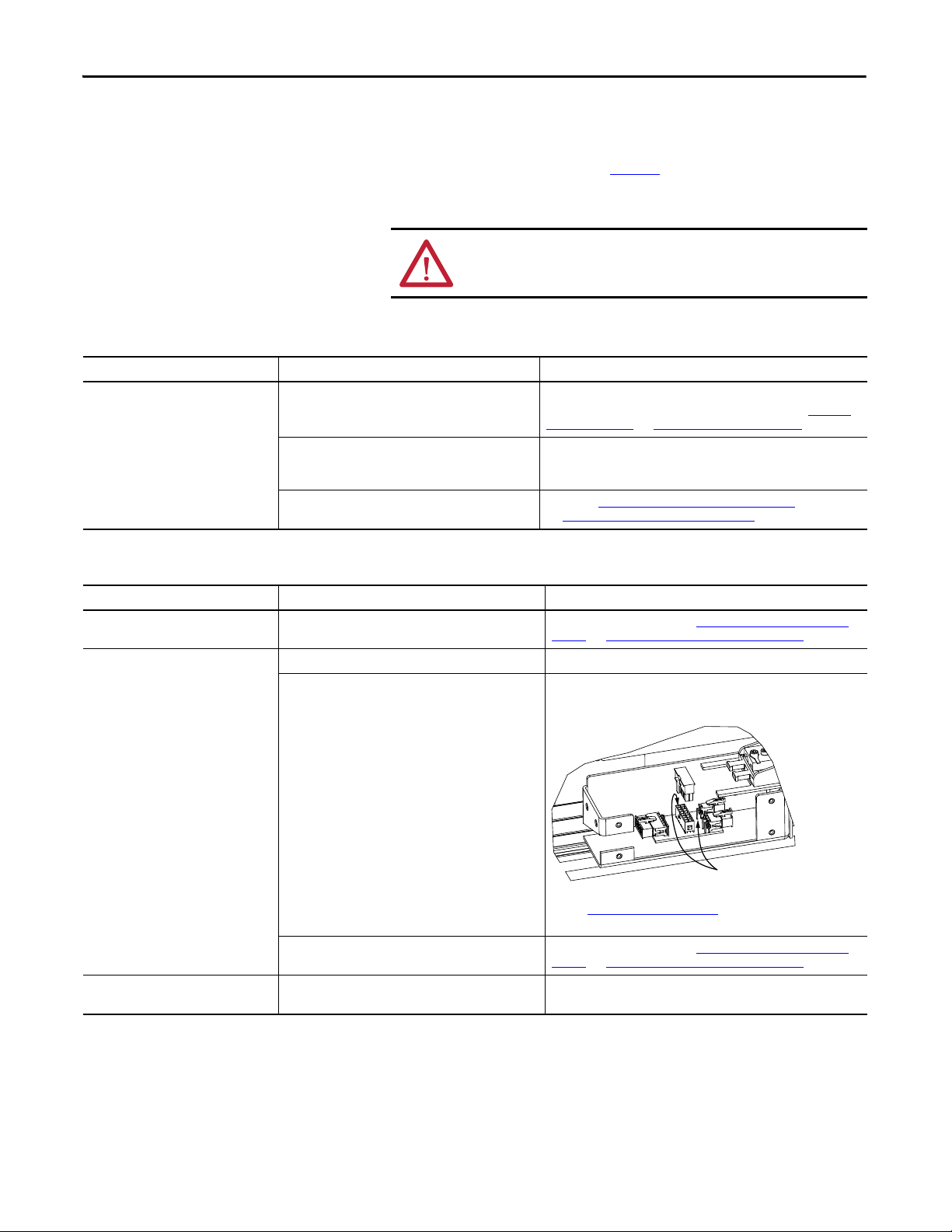
Chapter 9 Troubleshooting
Check resistance between J1 pin
8 and J2 pin 2
5. If excessive resistance is felt, clean and relubricate the linear bearings.
6. Perform the procedures for a ball screw linear stage listed in the
troubleshooting tables starting on page 72
.
7. If the problem persists, return for factory evaluation and possible repair.
ATTENTION: Lockout and tagout input power before servicing the
linear stage.
Table 9 - Troubleshooting for Direct Drive or Ball Screw Linear Stages
Symptom Possible Cause Solution
Kinetix 6000 drive or Kinetix 2000 drive
reporting error E19.
Ultra3000 reporting error E19, E22, or E23.
For sealed stages excess friction can be caused by
contamination on the strip seal.
Stage received a large impact. The ball screw or linear
bearings have become misali gned or there is damage to
the rails.
Linear bearing has excess friction. Refer to the Direct Drive Linear Stage Evaluation Procedure
Clean the strip seal with a clean, soft cloth wetted with isopropyl alcohol.
If problem persists, replace strip seal. Refer to instructions for Strip Seal
Removal on page 63 and Strip Seal Replacement on page 64.
Return stage to factory for evaluation and repair.
the Ball Screw Linear Stage Evaluation Procedure on page 71.
on page 71, or
Table 10 - Troubleshooting for Direct Drive Linear Stages
Symptom Possible Cause Solution
Intermittent reporting of error E11, E07, or
E20 by the drive.
Intermittent reporting of error E04 by the
drive.
Drive reporting error E07 or E20. Environment is electrically noisy and cable shield is
Cable carrier module exceeds its useful life of 10,000,000
cycles and is starting to fail.
Ambient temperature of the stage exceeds 40 °C (104 °F). Increase ventilation.
Thermistor circuit is defective. Disconnect the flex cable and probe the open Junction Box. At room
Cable carrier module exceeds its useful life of 10,000,000
cycles and is starting to fail.
compromised.
Replace cable carrier module. See Cable Carrier Assembly Removal on
page 62 and Cable Carrier Assembly Installation on page 62.
temperature 25 °C (77 °F), verify the resistance of the circuit is 100…200
Ohms. If not in range, return for factory service.
Refer to PTC Thermal Signal on page 42
at other temperature ranges.
Replace cable carrier module. See Cable Carrier Assembly Removal on
page 62 and Cable Carrier Assembly Installation on page 62.
Verify carrier cable module and extension cable shield termination are
secure.
for thermistor resistance values
72 Rockwell Automation Publication MP-UM001D-EN-P - September 2013
Page 73

Troubleshooting Chapter 9
Motor Power Connector Pin 1
Symptom Possible Cause Solution
Drive reporting error E05. Defective motor Disconnect the flex cable and probe the Motor Power connector (white
Mate-N-Lok) in the open Junction Box.
1. Measure the resistance between pins 1 and 2, pins 2 and 3, and pins 1
and 3, and evaluate the measurements with the following criteria:
– The resistance values varies depending on the MPAS model, but
must be less than 15 Ohms.
– The difference between the three resistance measurements must
be less than 1 Ohm.
2. There must be an open circuit between pins 1, 2, 3, and pin 4 (GND).
If any measurement is not in range, return for factory service.
Cable carrier module exceeds its useful life of 10,000,000
cycles and is starting to fail.
Replace cable carrier module. See Cable Carrier Assembly Removal on
page 62 and Cable Carrier Assembly Installation on page 62.
Table 11 - Troubleshooting for Ball Screw Linear Stages
Symptom Possible Cause Solution
Carriage is not moving but the controls
report axis motion.
Excessive carriage play. Motor coupling set screw is loose. Tighten motor coupling set screw.
Drive reporting error E05. Motor is damaged. Check that the phase-to-phase resistance of each motor phase. The
Kinetix 6000 drive or Kinetix 2000 drive
reporting error E19.
Ultra3000 drive reporting error E19, E22, or
E23.
Rotary motor coupling broken or slipping. Remove rotary motor and verify integrity of coupling.
Ball screw end blocks have excessive wear. Return stage to factory for service.
resistance must be equal, and not shorted to ground or to the shield.
Brake on the motor does not release. Manually release brake, and check that motor shaft is free to turn and the
bearing feels smooth.
Rockwell Automation Publication MP-UM001D-EN-P - September 2013 73
Page 74

Chapter 9 Troubleshooting
Notes:
74 Rockwell Automation Publication MP-UM001D-EN-P - September 2013
Page 75

Appendix A
Dimensions
Associated Kinetix publications listed in Additional Resources on page 10 and
information in product specifications can supersede the information in this
appendix.
Top ic Pag e
MP-Series Linear Stage Dimensions 75
MP-Series Linear Stage Dimensions
Linear stages are designed to metric dimensions. Inch dimensions are conversions
from millimeters. Untoleranced dimensions are for reference.
Rockwell Automation Publication MP-UM001D-EN-P - September 2013 75
Page 76

Appendix A Dimensions
7.6
(0.30)
239
(9.41)
165
(6.50)
(4X) M6 x 1.0-6H
37.0
(1.46)
12.0 (0.47)
25.0
(0.98)
25.0
(0.98)
167
(6.57)
165
(6.50)
54.5
(2.15)
(4X)
Ø 7.0 (0.28) Thru
Pilot Hole
45.0 (1.80)
130
(5.12)
30.0
(1.18)
125.5
(4.94)
46.8
(1.84)
181.5
(7.15)
8.5
(0.33)
31.9
(1.25)
92.0
(3.62)
150
(5.90)
123.8
(4.87)
Dimensions are in mm (in.)
Detail A
120 (4.72)
Toe Clamp/Tee Nut Spacing
Ø 13.0 (0.51) Through
Access Point to Lubricate
Ball Screw Nut
See Detail A
30.5 (1.20)
Mechanical Overtravel
(4X) M10 x 1.5-6H Through (2 per end cap)
Access point for lubricating linear bearings.
Provision to use lifting hooks (not provided).
Ground Screw
M5 x 0.8-6H
T- N ut
Mount to base by using
M6 x 1.0 hardware (optional accessory).
9.3 (0.37)
Depth, max
(S) Stage Length
(OAL) Overall Length
Toe Clamp is standard for
covered stages. Mount to base
by using M6 x 1.0 socket cap screw.
0.025 / 300 x 300 (0.001 / 12.0 x 12.0)
Flatness requirement for the surface
that this stage is being mounted to.
30.5 (1.20)
Mechanical Overtravel
The overall length (OAL) is measured to
the head of the screws that secure the
motor endcap.
Figure 16 - MP-Series Linear Stages (MPAS-A/B6xxx1/2-VxxSxA)
(1) If MPAS-A/B6xxx-V05S4A linear stage with brake, add 39 mm (1.53 in.) to dimension OAL.
(2) If MPAS-A/B6xxx-V20S4A linear stage with brake, add 39 mm (1.53 in.) to dimension OAL.
(3) If MPAS-A/B6xxx-V05S4A linear stage with brake, add 39 mm (1.53 in.) to dimension OAL.
Cat. No.
MPAS-
A/B6012x-VxxSxA 470 (18.5) 569 (22.4) 594 (23.4) A/B6036x-VxxSxA 710 (28.0) 809 (31.9) 834 (32.8)
A/B6018x-VxxSxA 530 (20.9) 629 (24.8) 654 (25.7) A/B6042x-VxxSxA 770 (30.3) 869 (34.2) 894 (35.2)
A/B6024x-VxxSxA 590 (23.2) 689 (27.1) 714 (28.1) A/B6054x-VxxSxA 890 (35.0) 989 (38.9) 1014 (39.9)
A/B6030x-VxxSxA 650 (25.6) 749 (29.5) 774 (30.5) A/B6066x-VxxSxA 1010 (39.8) 1109 (43.7) 1134 (44.6)
OAL
(20 mm/rev)
(2)
SOAL
(5 mm/rev)
(1)
mm (in.) mm (in.) mm (in.) mm (in.) mm (in.) mm (in.)
Cat. No.
MPAS-
SOAL
(5 mm/rev)
(3)
OAL
(20 mm/rev)
(2)
76 Rockwell Automation Publication MP-UM001D-EN-P - September 2013
Page 77

Figure 17 - MP-Series Linear Stages (MPAS-A/B8xxx1/2-VxxSxA)
Dimensions are in mm (in.)
Detail A
(2X) Ø 5.5 (0.22) Through
Pilot Hole
120 (4.72)
Toe Clamp/Square Nut Spacing
Ø 13.0 (0.51) Through
Access Point to Lubricate
Ball Screw Nut
See Detail A
25.4 (1.0)
Mechanical Overtravel
25.4 (1.0)
Mechanical Overtravel
Travel
(4X) M10 x 1.5-6H Through (2 per end cap)
Access point for lubricating linear bearings.
Provision to use lifting hooks (not provided).
Ground Screw
M5 x 0.8-6H
Square Nut
Mount to base by using
M6 x 1.0 hardware (optional accessory).
6.0 (0.24)
Depth, max
(S) Stage Length
(OAL) Overall Length
Toe Clamp is standard for
covered stages. Mount to base
by using M6 x 1.0 socket cap screw.
0.025 / 300 x 300 (0.001 / 12.0 x 12.0)
Flatness requirement for the surface
that this stage is being mounted to.
The overall length (OAL) is measured to
the head of the screws that secure the
motor endcap.
Dimensions Appendix A
8.5
(0.33)
37.8
(1.49)
232
(9.13)
130.8
(5.15)
200
(7.9)
5.22
(0.206)
46.8
(1.84)
215.7
(8.49)
25.4
(1.0)
239
(9.41)
30.0
(1.18)
130.8
(5.15)
(4X) M8 x 1.25-6H
(4X)
Ø 6.8 (0.27)
44.2
(1.74)
56.0
(2.20)
12.0 (0.47)
45.2 (1.78) Thru
25.4
(1.0)
216.8
(8.53)
105.4
(4.15)
Cat. No.
MPAS-
A/B8012x-VxxSxA 461 (18.1) 557 (21.9) 582 (22.9) A/B8054x-VxxSxA 881 (34.7) 977 (38.5) 1002 (39.5)
A/B8018x-VxxSxA 521 (20.5) 617 (24.3) 642 (25.3) A/B8066x-VxxSxA 1001 (39.4) 1097 (43.2) 1122 (44.2)
A/B8024x-VxxSxA 581 (22.9) 677 (26.6) 702 (27.6) A/B8078x-VxxSxA 1121 (44.1) 1217 (47.9) 1242 (48.9)
A/B8030x-VxxSxA 641 (25.2) 737 (29.0) 762 (30.0) A/B8090x-VxxSxA 1241 (48.8) 1337 (52.6) 1362 (53.6)
A/B8036x-VxxSxA 701 (27.6) 797 (31.4) 822 (32.4) A/B8102x-VxxSxA 1361 (53.6) 1457 (57.4) 1482 (58.4)
A/B8042x-VxxSxA 761 (29.9) 857 (33.7) 882 (34.7)
(1) If MPAS-A/B6xxx-V05S4A linear stage with brake, add 39 mm (1.53 in.) to dimension OAL.
(2) If MPAS-A/B6xxx-V20S4A linear stage with brake, add 39 mm (1.53 in.) to dimension OAL.
S OAL
mm (in.) mm (in.) mm (in.) mm (in.) mm (in.) mm (in.)
(5 mm/rev)
(1)
Rockwell Automation Publication MP-UM001D-EN-P - September 2013 77
OAL
(20 mm/rev)
(2)
Cat. No.
MPAS-
SOAL
(5 mm/rev)
(1)
OAL
(20 mm/rev)
(2)
Page 78

Appendix A Dimensions
281
(11.06)
46.8
(1.84)
8.5
(0.33)
38.3
(1.51)
172.2
(6.78)
249
(9.8)
30.0
(1.18)
105.4
(4.15)
5.60
(0.22)
239
(9.41)
130.8
(5.15)
(4X) M8 x 1.25-6H
(4X)
Ø 6.8 (0.27)
44.2
(1.74)
12.0 (0.47)
45.2 (1.78) Thru
265.8
(10.46)
25.4
(1.0)
56.4
(2.22)
264.7
(10.42)
25.4
(1.0)
281
(11.06)
46.8
(1.84)
8.5
(0.33)
38.3
(1.51)
172.2
(6.78)
249
(9.8)
30.0
(1.18)
105.4
(4.15)
5.60
(0.22)
239
(9.41)
130.8
(5.15)
(4X) M8 x 1.25-6H
(4X)
Ø 6.8 (0.27)
44.2
(1.74)
12.0 (0.47)
45.2 (1.78) Thru
265.8
(10.46)
25.4
(1.0)
56.4
(2.22)
264.7
(10.42)
25.4
(1.0)
Dimensions are in mm (in.)
Detail A
(2X) Ø 5.5 (0.22) Through
Pilot Hole
120 (4.72)
Toe Clamp/Tee Nut Spacing
Ø 13.0 (0.51) Through
Access Point to Lubricate
Ball Screw Nut
See Detail A
25.4 (1.0)
Mechanical Overtravel
25.4 (1.0)
Mechanical Overtravel
Travel
(4X) 9/16-12 UNC Through (2 per end cap)
Access point for lubricating linear bearings.
Provision to use lifting hooks (not provided).
Ground Screw
M5 x 0.8-6H
Tee Nut
Mount to base by using
M6 x 1.0 hardware (optional accessory).
6.5 (0.26)
Depth, max
(S) Stage Length
(OAL) Overall Length
Toe Clamp is standard for
covered stages. Mount to base
by using M6 x 1.0 socket cap screw.
0.025 / 300 x 300 (0.001 / 12.0 x 12.0)
Flatness requirement for the surface
that this stage is being mounted to.
The overall length (OAL) is measured to
the head of the screws that secure the
motor endcap.
Figure 18 - MP-Series Linear Stages (MPAS-A/B9xxx1/2-VxxSxA)
Cat. No.
MPAS-
A/B9012x-VxxSxA 461 (18.1) 557 (21.9) 582 (22.9) A/B9054x-VxxSxA 881 (34.7) 977 (38.5) 1002 (39.5)
A/B9018x-VxxSxA 521 (20.5) 617 (24.3) 642 (25.3) A/B9066x-VxxSxA 1001 (39.4) 1097 (43.2) 1122 (44.2)
A/B9024x-VxxSxA 581 (22.9) 677 (26.6) 702 (27.6) A/B9078x-VxxSxA 1121 (44.1) 1217 (47.9) 1242 (48.9)
A/B9030x-VxxSxA 641 (25.2) 737 (29.0) 762 (30.0) A/B9090x-VxxSxA 1241 (48.8) 1337 (52.6) 1362 (53.6)
A/B9036x-VxxSxA 701 (27.6) 797 (31.4) 822 (32.4) A/B9102x-VxxSxA 1361 (53.6) 1457 (57.4) 1482 (58.4)
A/B9042x-VxxSxA 761 (29.9) 857 (33.7) 882 (34.7)
(1) If MPAS-A/B6xxx-V05S4A linear stage with brake, add 39 mm (1.53 in.) to dimension OAL.
(2) If MPAS-A/B6xxx-V20S4A linear stage with brake, add 39 mm (1.53 in.) to dimension OAL.
(3) If MPAS-A/B6xxx-V20S4A linear stage with brake, add 39 mm (1.53 in.) to dimension OAL.
78 Rockwell Automation Publication MP-UM001D-EN-P - September 2013
SOAL
(5 mm/rev)
mm (in.) mm (in.) mm (in.) mm (in.) mm (in.) mm (in.)
(1)
OAL
(20 mm/rev)
(2)
Cat. No.
MPAS-
SOAL
(5 mm/rev)
(1)
OAL
(20 mm/rev)
(3)
Page 79

(4X) M6 x 1.0-6H
Dimensions are in mm (in.)
Detail A
120 (4.72)
Toe Clamp/
Tee Nut Spacing
Bracket ±51 (2.0)
from center of travel.
See Detail A
30.5 (1.20)
Mechanical
Overtravel
(4X) M10 x 1.5-6H Through (2 per end cap)
Access point for lubricating linear bearings.
Provision to use lifting hooks (not provided).
Ground Screw
M5 x 0.8-6H
T- N ut
Mount to base by using M6 x 1.0 hardware
(optional accessory).
9.3 (0.37)
Depth, max
(OAL) Overall Length
Toe Clamp is standard for
covered stages. Mount to base
by using M6 x 1.0 socket cap
screw.
0.025 / 300 x 300 (0.001 / 12.0 x 12.0)
Flatness requirement for the surface
that this stage is being mounted to.
30.5 (1.20)
Mechanical Overtravel
(CE) Cable Extensions
From End of Cable Carrier
Figure 19 - MP-Series Linear Stages (MPAS-A6xxxB-ALMx2C)
12.0 (0.47)
339
(13.35)
Dimensions Appendix A
Travel
(1.84)
8.5
(0.33)
32.0
(1.26)
46.8
181.5
(7.15)
92.0
(3.62)
150
(5.9)
238.6
(9.39)
25.0
(0.98)
(4X)
Ø 7.0 (0.28) Thru
45.0 (1.80)
123.8
(4.88)
Pilot Hole
(0.30)
7.6
30.0
(1.18)
165
(6.50)
130
(5.12)
87.0
(3.43)
104.5
(4.11)
25.0
(0.98)
167
(6.57)
Cat. No.
MPAS-
A6012B-ALMx2C 570 (22.4) 1220 (48.0) A6054B-ALMx2C 990 (39.0) 1020 (40.0)
A6018B-ALMx2C 630 (24.8) 1190 (47.0) A6066B-ALMx2C 1110 (43.7) 940 (37.0)
A6024B-ALMx2C 690 (27.2) 1170 (46.0) A6078B-ALMx2C 1230 (48.4) 890 (35.0)
A6030B-ALMx2C 750 (29.5) 1120 (44.0) A6090B-ALMx2C 1350 (53.1) 810 (32.0)
A6036B-ALMx2C 810 (31.9) 1090 (43.0) A6102B-ALMx2C 1470 (57.9) 1780 (70.0)
A6042B-ALMx2C 870 (34.3) 1070 (42.0) A6114B-ALMx2C 1590 (62.6) 1720 (68.0)
OAL CE
mm (in.) mm (in.) mm (in.) mm (in.)
Rockwell Automation Publication MP-UM001D-EN-P - September 2013 79
Cat. No.
MPAS-
OAL CE
Page 80
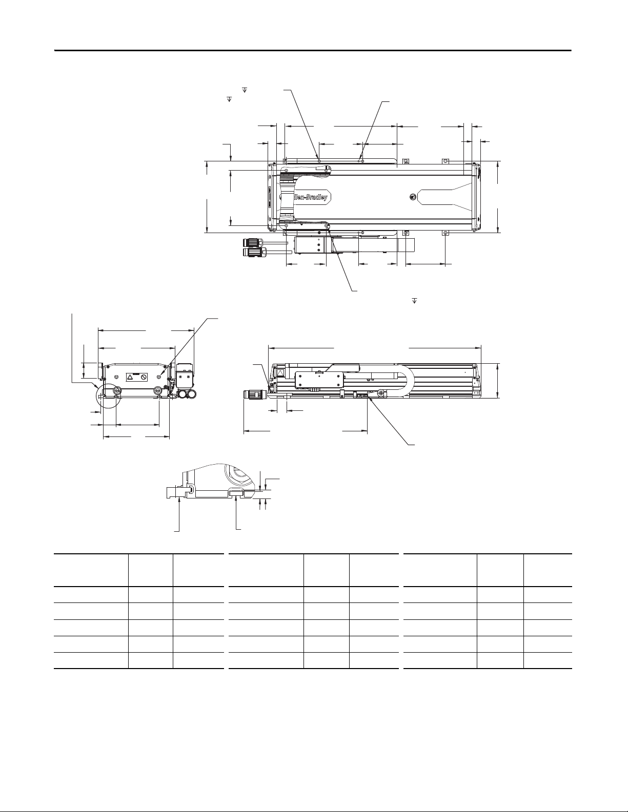
Appendix A Dimensions
25.4
(1.0)
339
(13.35)
130.8
(5.15)
104.1
(4.10)
216.7
(8.53)
116.4
(4.58)
Ø 5.8 (0.23) Thru
Ø 9.7 (0.38) Thru
14.2 (0.56)
120
(4.72)
35.0
(1.38)
105.5
(4.15)
(4X) M8 x 1.25-6H
(4X)
Ø 6.8 (0.27)
12.0 (0.47)
45.2 (1.78) Thru
215.7
(8.49)
166.6
(6.56)
28.0
(1.10)
232
(9.13)
288.9
(11.38)
46.8
(1.84)
8.5
(0.33)
37.8
(1.49)
130.8
(5.15)
200
(7.9)
5.2
(0.206)
25.4
(1.0)
Dimensions are in mm (in.)
Detail A
120 (4.72)
Toe Clamp/
Square Nut Spacing
Bracket ±51 (2.0)
from center of travel.
See Detail A
25.4 (1.0)
Mechanical Overtravel
(4X) M10 x 1.5-6H Through (2 per end cap)
Access point for lubricating linear bearings.
Provision to use lifting hooks (not provided).
Ground Screw
M5 x 0.8-6H
Square Nut
Mount to base by using M6 x 1.0 hardware
(optional accessory).
6.0 (0.24)
Depth, max
(OAL) Overall Length
Toe Clamp is standard for
covered stages. Mount to base
by using M6 x 1.0 socket cap screw.
0.025 / 300 x 300 (0.001 / 12.0 x 12.0)
Flatness requirement for the surface
that this stage is being mounted to.
25.4 (1.0)
Mechanical Overtravel
(CE) Cable Extensions
From End of Cable Carrier
(2X) Ø 5.5 (0.22) Through
Pilot Hole
Travel
Figure 20 - MP-Series Linear Stages (MPAS-A/B8xxxx-ALMx2C)
Cat. No.
MPAS-
A/B8014x-ALMx2C 581 (22.9) 1243 (49.0) A/B8044x-ALMx2C 881 (34.7) 1093 (43.0) A/B8104x-AL Mx2C 1481 (58.3) 1793 (71.0)
A/B8020x-ALMx2C 641 (25.2) 1218 (48.0) A/B8056x-ALMx2C 1001 (39.4) 1018 (40.0) A/B8128x-ALMx2C 1721 (67.8) 1668 (66.0)
A/B8026x-ALMx2C 701 (27.6) 1168 (46.0) A/B8068x-ALMx2C 1121 (44.1) 968 (38.0) A/B8152x-ALMx2C 1961 (77.2) 1543 (61.0)
OAL CE
mm (in.) mm (in.) mm (in.) mm (in.) mm (in.) mm (in.)
A/B8032x-ALMx2C 761 (30.0) 1143 (45.0) A/B8080x-ALMx2C 1241 (48.9) 918 (36.0) A/B8176x-ALMx2C 2201 (86.7) 1418 (56.0)
A/B8038x-ALMx2C 821 (32.3) 1118 (44.0) A/B8092x-ALMx2C 1361 (53.6) 843 (33.0) A/B8194x-ALMx2C 2381 (93.7) 1343 (53.0)
Cat. No.
MPAS-
OAL CE
Cat. No.
MPAS-
OAL CE
80 Rockwell Automation Publication MP-UM001D-EN-P - September 2013
Page 81
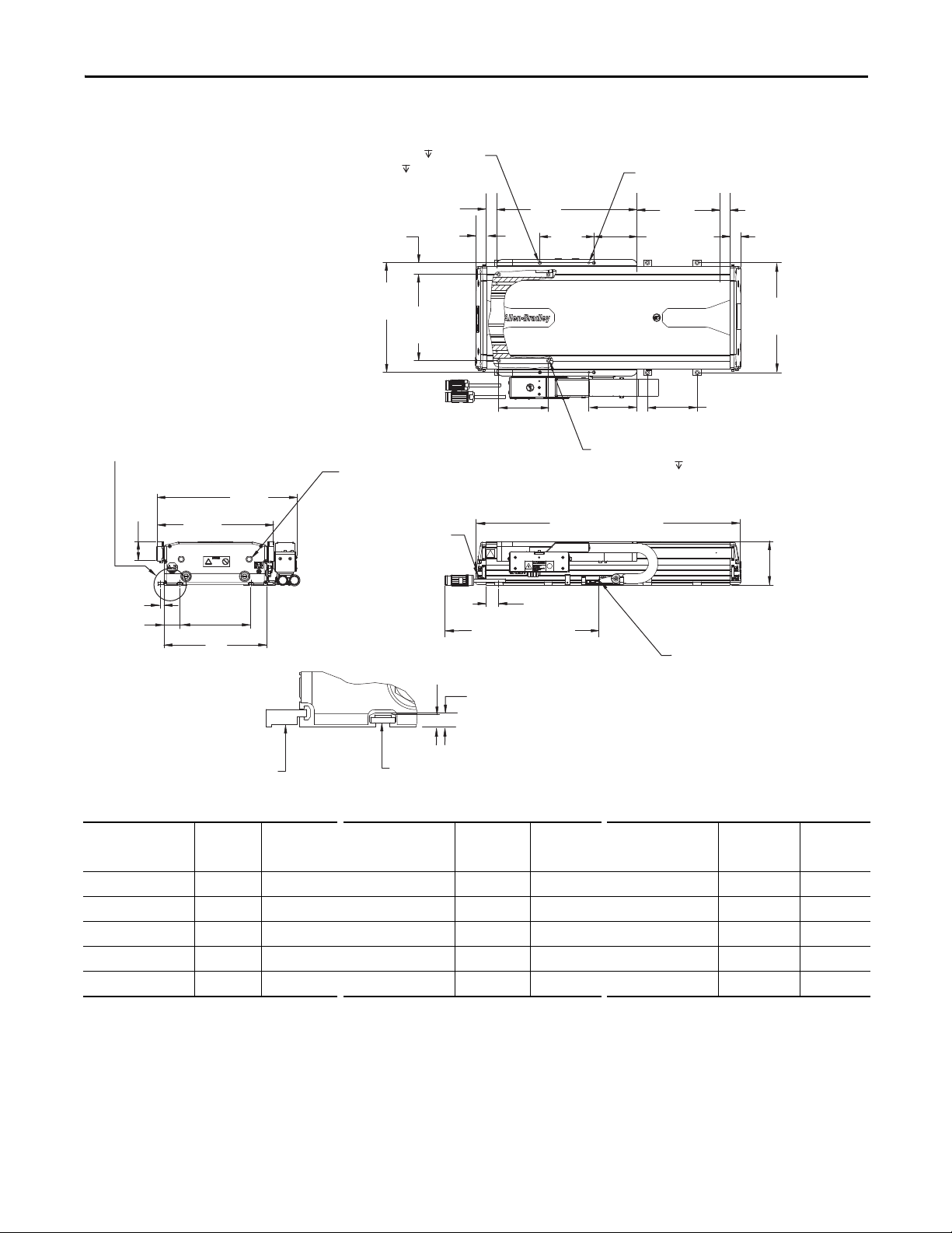
Figure 21 - MP-Series Linear Stages (MPAS-A/B9xxxx-ALMx2C)s
25.4
(1.0)
339
(13.35)
130.8
(5.15)
104.1
(4.10)
265.7
(10.46)
116.4
(4.58)
Ø 5.8 (0.23) Thru
Ø 9.7 (0.38) Thru
14.2 (0.56)
120
(4.72)
30.0
(1.18)
105.4
(4.15)
(4X) M8 x 1.25-6H
(4X)
Ø 6.8 (0.27)
12.0 (0.47)
45.2 (1.78) Thru
264.7
(10.42)
208.6
(8.21)
28.0
(1.10)
281
(11.06)
338.14
(13.31)
46.8
(1.84)
8.5
(0.33)
38.3
(1.51)
172.2
(6.78)
249
(9.8)
5.6
(0.22)
25.4
(1.0)
Dimensions are in mm (in.)
Detail A
120 (4.72)
Toe Clamp/T- Nut Spacing
Bracket ±51 (2.0)
from center of travel.
See Detail A
25.4 (1.0)
Mechanical Overtravel
Ground Screw
M5 x 0.8-6H
T- N ut
Mount to base by using M6 x 1.0 hardware
(optional accessory).
6.5 (0.26)
Depth, max
(OAL) Overall Length
Toe Clamp is standard for
covered stages. Mount to base
by using M6 x 1.0 socket cap
screw.
0.025 / 300 x 300 (0.001 / 12.0 x 12.0)
Flatness requirement for the surface
that this stage is being mounted to.
25.4 (1.0)
Mechanical Overtravel
(CE) Cable Extensions
From End of Cable Carrier
(2X) Ø 5.5 (0.22) Through
Pilot Hole
Travel
(4X) 9/16-12 UNC Through (2 per end cap)
Access point for lubricating linear bearings.
Provision to use lifting hooks (not provided).
Dimensions Appendix A
Cat. No.
MPAS-
OAL CE
mm (in.) mm (in.) mm (in.) mm (in.) mm (in.) mm (in.)
A/B9014x-ALMx2C 581 (22.9) 1243 (49.0) A/B9044x-ALMx2C 881 (34.7) 1093 (43.0) A/B9104x-ALMx2C 1481 (58.3) 1793 (71.0)
A/B9020x-ALMx2C 641 (25.2) 1218 (48.0) A/B9056x-ALMx2C 1001 (39.4) 1018 (40.0) A/B9128x-ALMx2C 1721 (67.8) 1668 (66.0)
A/B9026x-ALMx2C 701 (27.6) 1168 (46.0) A/B9068x-ALMx2C 1121 (44.1) 968 (38.0) A/B9152x-ALMx2C 1961 (77.2) 1543 (61.0)
A/B9032x-ALMx2C 761 (30.0) 1143 (45.0) A/B9080x-ALMx2C 1241 (48.9) 918 (36.0) A/B9176x-ALMx2C 2201 (86.7) 1418 (56.0)
A/B9038x-ALMx2C 821 (32.3) 1118 (44.0) A/B9092x-ALMx2C 1361 (53.6) 843 (33.0) A/B9194x-ALMx2C 2381 (93.7) 1343 (53.0)
Cat. No.
MPAS-
OAL CE
Cat. No.
MPAS-
OAL CE
Rockwell Automation Publication MP-UM001D-EN-P - September 2013 81
Page 82

Appendix A Dimensions
Notes:
82 Rockwell Automation Publication MP-UM001D-EN-P - September 2013
Page 83
Appendix B
Accessories
Top ic Pag e
Installation, Maintenance, and Replacement Kits 83
Installation, Maintenance, and Replacement Kits
Table 12 - Accessories Common to Ball Screw and Direct Drive Linear Stages
Description Catalog Number Comments
Grease Pump Maintenance Kit MPAS-GPUMP Includes grease pump, one grease cartridge, and all necessary tips.
Grease Cartridge MPAS-CART Refill cartridge for grease pump.
Toe Clamp Installation Kit MPAS-TOE 10 toe clamps per package
Tee Nut Installation Kit MPAS-6-TNUT 10 Tee nuts per package
Table 13 - Accessories for Ball Screw Linear Stages
Description Catalog Number Comments
Couplers MPAS-6-COUP
MPAS-8-COUP
MPAS-9-COUP
Rotary Servo Motors MPLS-A210E-V-x246 230V non-brake motor for 5 mm/rev ball screw
MPLS-A210E-V-x247 230V brake motor for 5 mm/rev ball screw
MPLS-B210E-V-x248 460V non-brake motor for 5 mm/rev ball screw
MPLS-B210E-V-x249 460V brake motor for 5 mm/rev ball screw
MPLS-A220H-V-x250 230V non-brake motor for 20 mm/rev ball screw
MPLS-A220H-V-x251 230V brake motor for 20 mm/rev ball screw
MPLS-B220H-V-x252 460V non-brake motor for 20 mm/rev ball screw
MPLS-B220H-V-x253 460V brake motor for 20 mm/rev ball screw
Strip Seal Replacement Kits MPAS-6xxx1-SEAL xxx = cm stroke:
MPAS-8xxx1-SEAL xxx = cm stroke:
MPAS-9xxx1-SEAL xxx = cm stroke:
Accessories available for installing linear stages, replacing items, and performing
maintenance at regular intervals are listed in the tables that follow.
MPAS-8-TNUT
MPAS-9-TNUT
012, 018, 024, 030, 036, 042, 054, or 066
012, 018, 024, 030, 036, 042, 054, 066, 078, 090, or 102
012, 018, 024, 030, 036, 042, 054, 066, 078, 090, or 102
Rockwell Automation Publication MP-UM001D-EN-P - September 2013 83
Page 84

Appendix B Acc essories
Table 13 - Accessories for Ball Screw Linear Stages (continued)
Description Catalog Number Comments
Side Covers Replacement Kits MPAS-6xxx1-SIDE xxx = cm stroke:
MPAS-8xxx1-SIDE xxx = cm stroke:
MPAS-9xxx1-SIDE xxx = cm stroke:
Top Cover Replacement Kits MPAS-6xxx1-TOP xxx = cm stroke:
MPAS-8xxx1-TOP xxx = cm stroke:
MPAS-9xxx1-TOP xxx = cm stroke:
012, 018, 024, 030, 036, 042, 054, or 066
012, 018, 024, 030, 036, 042, 054, 066, 078, 090, or 102
012, 018, 024, 030, 036, 042, 054, 066, 078, 090, or 102
012, 018, 024, 030, 036, 042, 054, or 066
012, 018, 024, 030, 036, 042, 054, 066, 078, 090, or 102
012, 018, 024, 030, 036, 042, 054, 066, 078, 090, or 102
Table 14 - Accessories for Direct Drive Linear Stages
Description Catalog Number Comments
Cable Carrier Modules MPAS-6xxxB-CABLE xxx = cm stroke:
MPAS-8xxxE-CABLE xxx = cm stroke:
MPAS-9xxxK-CABL E xxx = cm stroke:
Strip Seal Replacement Kits MPAS-6xxxB-SEAL xxx = cm stroke:
MPAS-8xxxE-SEAL xxx = cm stroke:
MPAS-9xxxK-SEAL xxx = cm stroke:
Side Covers Replacement Kit MPAS-6xxxB-SIDE xxx = cm stroke:
MPAS-8xxxE-SIDE xxx = cm stroke:
MPAS-9xxxK-SIDE xxx = cm stroke:
Top Cover Replacement Kit MPAS-6xxxB-TOP xxx = cm stroke:
MPAS-8xxxE-TOP xxx = cm stroke:
MPAS-9xxxK-TOP xxx = cm stroke:
012, 018, 024, 030, 036, 042, 054, 066, 078, 090, 102, or 114
014, 020, 026, 032, 038, 044, 056, 068, 080, 092, 104, 128, 152, 176, or 194
014, 020, 026, 032, 038, 044, 056, 068, 080, 092, 104, 128, 152, 176, or 194
012, 018, 024, 030, 036, 042, 054, 066, 078, 090, 102, or 114
014, 020, 026, 032, 038, 044, 056, 068, 080, 092, 104, 128, 152, 176, or 194
014, 020, 026, 032, 038, 044, 056, 068, 080, 092, 104, 128, 152, 176, or 194
012, 018, 024, 030, 036, 042, 054, 066, 078, 090, 102, or 114
014, 020, 026, 032, 038, 044, 056, 068, 080, 092, 104, 128, 152, 176, or 194
014, 020, 026, 032, 038, 044, 056, 068, 080, 092, 104, 128, 152, 176, or 194
012, 018, 024, 030, 036, 042, 054, 066, 078, 090, 102, or 114
014, 020, 026, 032, 038, 044, 056, 068, 080, 092, 104, 128, 152, 176, or 194
014, 020, 026, 032, 038, 044, 056, 068, 080, 092, 104, 128, 152, 176, or 194
84 Rockwell Automation Publication MP-UM001D-EN-P - September 2013
Page 85
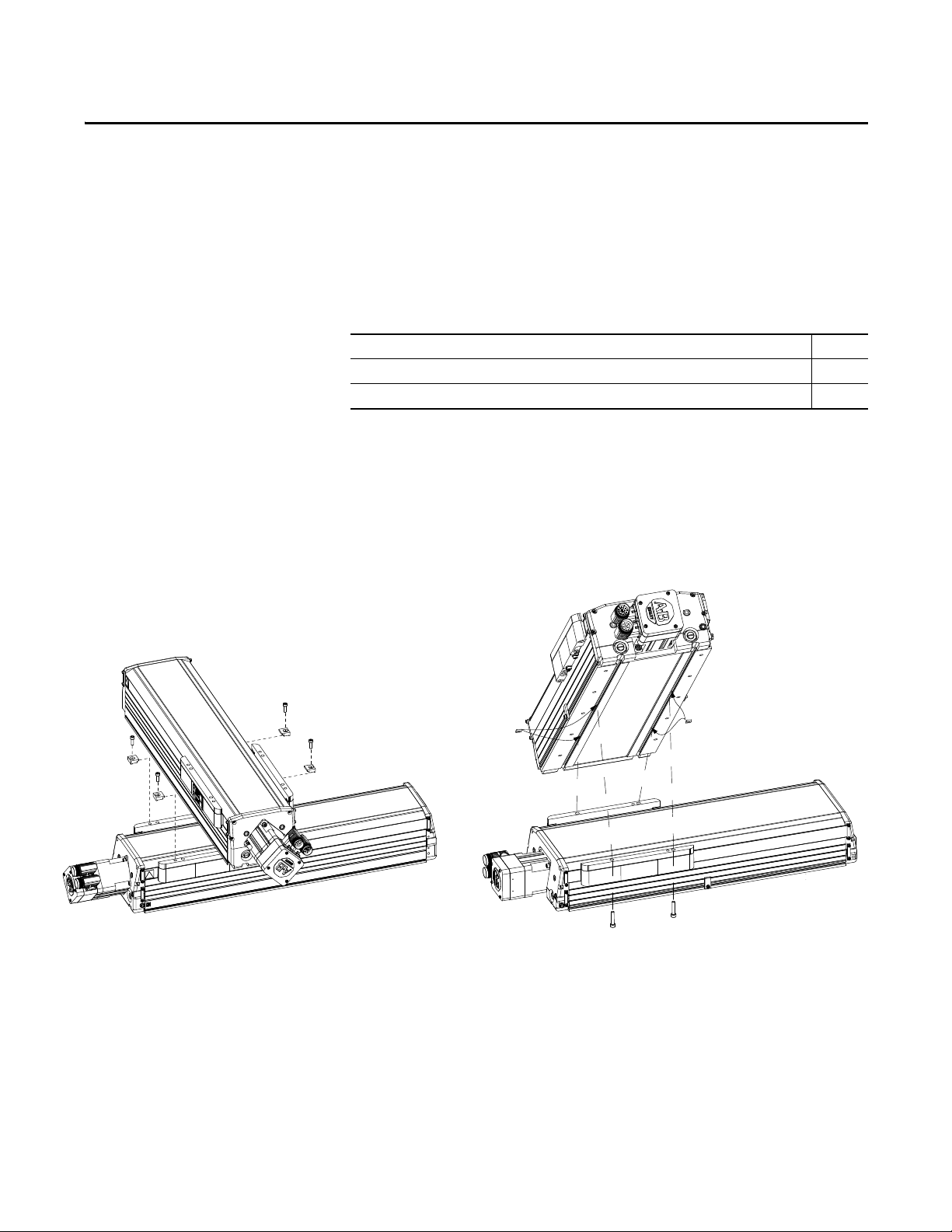
Appendix C
The MPAS-x8xxxx is capable of mounting to
the top of either a MPAS-x8xxxx or a MPAS-x9xxxx
by bolting through the slide on the bottom stage and
into T-nut slots on the top stage.
The MPAS-x6xxxx is capable of mounting to
the top of another MPAS-x6xxxx by bolting
through toe-clamps to the slide on the bottom stage.
Stacking Stages
This appendix provides information about center-stacked stage configurations.
Top ic Pag e
Stage Stacking 85
Specifications for Stacked Stages 86
Stage Stacking
Certain combinations of MPAS linear stages are designed to be stacked on top of
one another. Stacking forms an X-Y axis arrangement. A center-stack
arrangement mounts the top axis in the middle of the bottom axis. The top stage
is centered on the bottom stage.
Figure 22 - Stacking Stages
Rockwell Automation Publication MP-UM001D-EN-P - September 2013 85
Page 86

Appendix C Stacking Stages
Specifications for Stacked Stages
Linear stage specifications are based on mounting the stage to a precision base
along the entire length of the stage, and stage specifications follow this
convention. In the case of stacked stages, the top axis is no longer supported along
its entire length, and this alters both the precision and the load carrying capability
of that stage. Furthermore, linear stage specifications are based on a specified test
payload with a low center of gravity that is centered on the carriage. Deviations
from the test payload condition impacts the performance of both the top and
bottom linear stages.
The following table provides information about the payload that the top stage, or
axis, can carry without derating the life of its bearings from those specified for the
same stage mounted as a single-axis stage on a precision base.
Table 15 - Centered Stack Combinations Not Requiring Derating
Catalog Numbers of
Centered Stack Linear Stages
MPAS-x6xxxx on MPAS-x6xxxx
Ball Screw
or Direct Drive
MPAS-x8xxxx on MPAS-x8xxxx
Direct Drive
MPAS-x8xxxx on MPAS-x9xxxx
Direct Drive
MPAS-x8xxxx on MPAS-x8xxxx
Ball Screw
MPAS-x8xxxx on MPAS-x9xxxx
Ball Screw
Y-axis Travel Allowable Mass of Payload
300 10.0 kg (22 lb)
420 8.0 kg (17.6 lb)
540 5.0 kg (11 lb)
660 4.0 kg (8.8 lb)
320 14.0 kg (30.8 lb)
560 6.5 kg (14.3 lb)
800 3.0 kg (6.6 lb)
320 14.0 kg (30.8 lb)
560 6.5 kg (14.3 lb)
800 3.0 kg (6.6 lb)
300 14.0 kg (30.8 lb)
540 6.5 kg (14.3 lb)
780 3.0 kg (6.6 lb)
300 14.0 kg (30.8 lb)
540 6.5 kg (14.3 lb)
780 3.0 kg (6.6 lb)
(1)
(1) Payload is based solely on bearing and structure limitations.
For other stacking arrangements, please contact Rockwell Automation and ask
for Application Engineering.
86 Rockwell Automation Publication MP-UM001D-EN-P - September 2013
Page 87

Appendix D
Interconnect Diagrams
This appendix provides wiring examples to assist you in wiring an Bulletin MPAS
linear stage to a Allen-Bradley drive.
Top ic Pag e
Wiring Examples 87
Motor/Axis Module Wiring Examples 88
Wiring Examples
The notes below apply to the wiring examples on the pages that follow.
Not all of the notes apply to each example.
Note Information
1 Cable shield clamp must be used to meet CE requirements. No external connec tion to ground is required.
2 The Kinetix 2000 or Kinetix 6000 axis module referenced is either an individual axis module or the same axis module that resides within an multi-axis system.
3 For motor cable specifications, refer to the Kinetix Motion Control Accessories Technical Data, publication GMC-TD004.
4 MPAS-Axxxxxx encoders use the +5V DC supply. MPAS-Bxxxxxx encoders use +9V DC.
5 Use a flyback diode for noise suppression of the motor brake coil of an Ultra3000 drive. For more information, refer to System Design for Control of Electrical Noise,
publication GMC-RM001.
Rockwell Automation Publication MP-UM001D-EN-P - September 2013 87
Page 88

Appendix D Interconnect Diagrams
BR+
BR-
W
V
U
0
1
2
3
4
5
6
7
8
9
10
11
12
13
14
15
SIN+
SIN-
COS+
COS-
DATA+
DATA-
+5VDC
ECOM
GREEN
WHT/GREEN
GR A Y
WHT/GR AY
BLACK
WHT/BLACK
RED
WHT/RED
3
4
5
6
1
2
9
10
1
2
3
4
5
10
14
6
14
12
+9VDC
TS+
ORANGE
WHT/ORANGE
11
13
7
11
4
3
2
1
Green/ Yellow
Blue
Black
Brown
Black
White
GND
W
V
U
GND
Shield
W
V
U
TS-
COM
BLUE
AM+
AM-
BM+
BM-
IM+
IM-
+5VDC
ECOM
BLUE
WHT/BLUE
GREEN
WHT/GREEN
GR A Y
WHT/GR AY
BLACK
WHT/BLACK
RED
WHT/RED
1
2
3
4
5
10
14
6
12
TS-
S1
–
TS+
ORANGE
WHT/ORANGE
11
S2
S3
COM
YELLOW
WHT/YELLOW
13
8
3
4
5
6
1
2
14
15
16
17
12
11
13
9
10
D
C
B
A
F
G
D
C
B
A
MPAS-A/Bxxxx-V05SxA and
MPAS-A/Bxxxx-V20Sx A
Ball Screw Stages with
High Resolution Feedback
2090-CPWM7DF-16AAxx
(standard)
or 2090-CPBM7DF-16AAxx
(with brake)
Motor Power Cable
Note 3,5
Use 2090-CPWM7DF-16AFxx
cable for continuous-ex
non-brake applications.
Thermostat
Three-Phase
Motor Power
Brake
KINETIX 2000
IAM (inverter) or AM
Note 1
Cable Shield
Clamp Kit
Motor Power
(MP) Connector
Motor Feedback
(MF) Connector
(IAM/AM)
2090-CFBM7DF-CEAAxx (standard) or
2090-CFBM7DF-CEAFxx (continuous-ex)
(ying-lead) Feedback Cable
Notes 3, 4
Motor
Feedback
Motor Feedback
(MF) Connector
Thermostat
Three-Phase
Motor Power
Motor Feedback
(MF) Connector
(IAM/AM)
Refer to Low Prole Connector
illustration (lower left)
for proper grounding technique.
Exposed shield secured
under clamp
Clamp
Turn clamp over to hold
small cables secure
Clamp screw
Low Prole Connector
(2090-K2CK-D15M shown)
Grounding Technicque for
Feedback Cable Shield
Connection to Drive
2090-XXNFMF-Sxx (standard) or
2090-CFBM7DF-CDAFxx (continuous ex)
Feedback Cable
Motor
Feedback
Refer to Low Prole Connector
illustration (lower left)
for proper grounding technique.
2
3
1
4
MBRK +
MBRK -
PWR
COM
24V DC
User Supplied
Motor
Brake
(BC)
Connector
Motor Power Cable
connects to Motor Power (MP)
and Cable Shield Clamp
as shown above
MPAS-A/Bxxxx-ALMx2C
Direct Drives Stages with
Incremental Feedback
Motor/Axis Module Wiring Examples
Figure 23 - Wiring Examples for MP-Series Linear Stages and Kinetix 2000 Drives
88 Rockwell Automation Publication MP-UM001D-EN-P - September 2013
Page 89
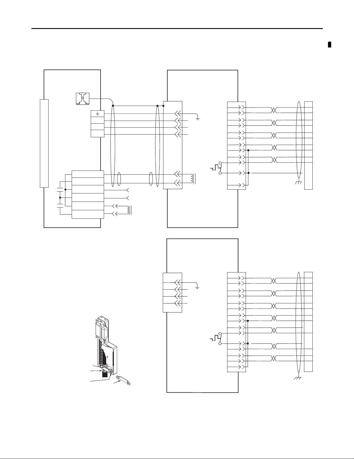
Interconnect Diagrams Appendix D
D
C
B
A
BR+
BR-
F
G
W
V
U
0
1
2
3
4
5
6
7
8
9
10
11
12
13
14
15
SIN+
SIN-
COS+
COS-
DATA+
DATA-
+5VDC
ECOM
GREEN
WHT/GREEN
GR A Y
WHT/GR AY
BLACK
WHT/BLACK
RED
WHT/RED
3
4
5
6
1
2
9
10
1
2
3
4
5
10
14
6
14
12
+9VDC
TS+
ORANGE
WHT/ORANGE
11
13
7
11
4
3
2
1
6
5
4
3
2
1
Green/ Yellow
Blue
Black
Brown
Black
White
GND
W
V
U
GND
Shield
W
V
U
MBRK -
MBRK +
COM
PWR
DBRK -
DBRK +
BR+
BR-
TS-
COM
BLUE
AM+
AM-
BM+
BM-
IM+
IM-
+5VDC
ECOM
BLUE
WHT/BLUE
GREEN
WHT/GREEN
GR A Y
WHT/GR AY
BLACK
WHT/BLACK
RED
WHT/RED
1
2
3
4
5
10
14
6
12
TS-
S1
–
TS+
ORANGE
WHT/ORANGE
11
S2
S3
COM
YELLOW
WHT/YELLOW
13
8
3
4
5
6
1
2
14
15
16
17
12
11
13
9
10
D
C
B
A
User Supplied
24V DC
MPAS-A/Bxxxx-V05SxA and
MPAS-A/Bxxxx-V20SxA
Ball Screw Stage with
High Resolution Feedback
Thermostat
Three-Phase
Motor Power
Brake
KINETIX 6000
IAM (inverter) or AM
Note 2
Cable Shield
Clamp
Note 1
Motor Power
(MP) Connector
Motor/Resistive
Brake (BC) Connector
Resistive Brake
Connections
Motor Feedback
(MF) Connector
(IAM/AM)
Motor
Feedback
Motor Feedback
(MF) Connector
MPAS-A/Bxxxx-ALMx2C
Direct Drive Stages with
Incremental Feedback
Thermostat
Three-Phase
Motor Power
Motor Feedback
(MF) Connector
(IAM/AM)
Refer to Low Prole Connector
illustration (lower left)
for proper grounding technique.
Exposed shield secured
under clamp
Clamp
Turn clamp over to hold
small cables secure
Clamp screw
Low Prole Connector
(2090-K6CK-D15M shown)
Grounding Technique for
Feedback Cable Shield
Connection to Drive
Motor
Feedback
Refer to Low Prole Connector
illustration (lower left)
for proper grounding technique.
Motor Power Cable
connects to Motor Power (MP)
and Cable Shield Clamp
as shown above
2090-CPWM7DF-16AAxx
(standard)
or 2090-CPBM7DF-16AAxx
(with brake)
Motor Power Cable
Note 3
Use 2090-CPWM7DF-16AFxx
cable for continuous-ex
non-brake applications.
2090-CFBM7DF-CEAAxx (standard) or
2090-CFBM7DF-CEAFxx (continuous-ex)
(ying-lead) Feedback Cable
Note 3,4
2090-XXNFMF-Sxx (standard) or
2090-CFBM7DF-CDAFxx (continuous-ex)
(ying-lead) Feedback Cable
Note 3,4
Figure 24 - Wiring Examples for MP-Series Linear Stages and Kinetix 6000 Drives
Rockwell Automation Publication MP-UM001D-EN-P - September 2013 89
Page 90

Appendix D Interconnect Diagrams
1
2
3
4
5
10
14
6
7
11
D
C
B
A
BR+
BR-
F
G
W
V
U
0
1
2
3
4
5
6
7
8
9
10
11
12
13
14
15
SIN+
SIN-
COS+
COS-
DATA+
DATA-
+5VDC
ECOM
GREEN
WHT/GREEN
GR A Y
WHT/GR AY
BLACK
WHT/BLACK
RED
WHT/RED
3
4
5
6
1
2
9
10
14
12
+9VDC
TS+
ORANGE
WHT/ORANGE
11
13
4
3
2
1
Green/ Yellow
Blue
Black
Brown
Black
White
GND
W
V
U
GND
Shield
W
V
U
D
C
B
A
TS-
COM
BLUE
AM+
AM-
BM+
BM-
IM+
IM-
+5VDC
ECOM
BLUE
WHT/BLUE
GREEN
WHT/GREEN
GR A Y
WHT/GR AY
BLACK
WHT/BLACK
RED
WHT/RED
1
2
3
4
5
10
14
6
12
TS-
S1
–
TS+
ORANGE
WHT/ORANGE
11
S2
S3
COM
YELLOW
WHT/YELLOW
13
8
3
4
5
6
1
2
14
15
16
17
12
11
13
9
10
BRK -
BRK+
43
44
+24VCOM
User Supplied
24V DC
Note 5
MPAS-A/BxxxxV05SxA and
MPAS-A/BxxxxV20SxA
Ball Screw Stage with
High Resolution Feedback
Thermostat
Three-Phase
Motor Power
Brake
Ultra3000
Digital Servo Drive
Note 2
Cable Shield
Clamp
Note 1
Motor Power
(TB1) Connector
Control Interface
(CN1) Connector
Motor Feedback
(CN2) Connector
Motor
Feedback
Motor Feedback
(CN2) Connector
MPAS-A/Bxxxx-ALMx2C
Direct Drive Stages with
Incremental Feedback
Thermostat
Three-Phase
Motor Power
Motor Feedback
(CN2) Connector
Motor
Feedback
Refer to Low Prole Connector
illustration (lower left)
for proper grounding technique.
Motor Power Cable
connects to Motor Power (TB1)
and Cable Shield Clamp
as shown above
Locking Tab
Cable Tie
Mounting Screws (2)
Shrink-wrapped
Insulation
Cable
Tie
Position cable shield against
this termination pad.
Cable
Shield
2090-CPWM7DF-16AAxx
(standard)
or 2090-CPBM7DF-16AAxx
(with brake)
Motor Power Cable
Note 3
Use 2090-CPWM7DF-16AFxx
cable for continuous-ex
non-brake applications.
2090-CFBM7DF-CEAAxx (standard) or
2090-CFBM7DF-CEAFxx (continuous-ex)
(ying-lead) Feedback Cable
Note 3,4
2090-XXNFMF-Sxx (standard) or
2090-CFBM7DF-CDAFxx (continuous ex)
Feedback Cable
Note 3,4
Grounding Technique for
Feedback Cable Shield
Connection to Drive
Figure 25 - Wiring Examples for MP-Series Linear Stages and Ultra3000 Drives
90 Rockwell Automation Publication MP-UM001D-EN-P - September 2013
Page 91

Appendix
E
Home to Torque-level Example
Use this appendix to become familiar with the Home to Torque-level sequence in
RSLogix 5000 software, version 16.xx or later or the Logix Designer application,
and the considerations required when using this homing method.
This document provides an example for a typical homing program routine. The
example shown does not claim to be complete and does not apply to any specific
application.
Top ic Pa ge
Applicable Drives 91
About Home to Torque-level Homing 92
Drive Bipolar Torque Limit Adjustment 94
Disable Soft Overtravel Limit 95
Ladder Code Example 95
Potentia l for Posi tion Error 102
Applicable Drives
This information in this document applies to the following drives.
Drive Type Catalog Number
Kinetix 2000 2093-AC05-MPx, 2093-AMxx
Kinetix 6000 2094-ACxx-Mxx, 2094-AMxx, 2094-ACxx-Mxx-S, 2094-AMxx-S,
2094-BCxx-Mxx, 2094-BMxx, 2094-BCxx-Mxx-S, 2094-BMxx-S
Rockwell Automation Publication MP-UM001D-EN-P - September 2013 91
Page 92

Appendix E Home to Torque-level Example
IMPORTANT
About Home to Torque-level Homing
Home to torque-level homing is a process that references a known position by
monitoring torque while driving an axis into a mechanical hard-stop. Once the
actual torque level reaches or exceeds a specified torque level for a set time of
500 ms, a status flag is set in the controller.
Because the process of home to torque-level requires axis motion,
the axis homing mode must be configured as Active.
Figure 26 - Axis Properties - Homing Tab
Table 16 - Torque-level Homing
Sequence Type Description
Torque Level Sets the Home Position after the output torque reaches the Torque Level value, reverses
Torque Level - Marker Sets the Home Position after the output torque reaches the Torque Level value, reverses
direction, and moves until the Homing Torque Above Threshold bit is low and the status
bit sets.
direction, and encounters an encoder marker.
When either the Torque Level or Torque Level - Marker homing option is
selected on the Homing tab, the Torque Level field is activated in the Active
Home Sequence Group. The units for this field are a percentage of the
continuous torque of the motor (% Continuous Torque) limited by the driverated current/motor-rated current ratio. This number is interpreted in the drive
as an absolute value and the range is 0 through the TorqueLimitPositive value.
The options for the Direction field when Torque Level or Torque Level - Marker
homing sequence is selected are only Forward Bi-directional and Reverse Bidirectional. Uni-directional homing is not possible, because the Home to Torquelevel sequence relies on a mechanical hard-stop.
92 Rockwell Automation Publication MP-UM001D-EN-P - September 2013
Page 93

Home to Torque-level Example Appendix E
Figure 27 - Position/Velocity Diagram for Torque-level Homing
Figure 28 - Position/Velocity Diagram for Torque-level - Marker Homing
Rockwell Automation Publication MP-UM001D-EN-P - September 2013 93
Page 94

Appendix E Home to Torque-level Example
IMPORTANT
Drive Bipolar Torque Limit Adjustment
When homing an axis to a mechanical hard-stop, set the Home Torque-level
value above the torque value required to move the system, but low enough not to
cause problems with the system mechanics. As part of the process of homing to a
torque limit, limit the Peak Torque value to a level 10% above the Home Torque
value to reduce the stresses on the mechanics and to eliminate the chance of an
over-current error.
The 10% value is an estimated starting point. This value can
need adjustment based on the application requirements.
Limit the Peak Torque value before issuing the homing instruction (MAH) and
reset the Peak Torque field to the original value after homing completes.
Figure 29 - Bipolar Torque Limit Adjustment
94 Rockwell Automation Publication MP-UM001D-EN-P - September 2013
Page 95

Home to Torque-level Example Appendix E
IMPORTANT
IMPORTANT
Disable Soft Overtravel Limit
Ladder Code Example
If the application requires the use of soft-overtravel limits (Limits tab) to
safeguard the system mechanics, disable the Soft Travel Limits for the axis to
home. The Soft Travel Limits are disabled to prevent an error from occurring
during the homing operation, but re-enable them after homing completes.
Those responsible for the application must determine when it is
safe and appropriate to disable soft-overtravel checking.
This example shows how to adjust the peak torque limit and disable the softovertravel limit checking when homing to a torque limit. The code uses a state
model methodology in that each rung of code needs to complete successfully
before moving to the next rung.
Because the home to torque-level sequence relies on the
mechanical end of travel for operation, Uni-directional homing is
not possible. You must choose between Forward Bi-directional or
Reverse Bi-directional.
Rung 11 of the ladder code checks to make sure that the axis position, after
homing, is within the Soft Travel Limits before re-enabling soft-overtravel limit
checking. In this example a 1.15 cm Offset move is configured in the Homing tab
and that is the final home position. The 0.5 cm is within the Soft Travel Limits
set on the Limits tab.
Table 17 - Tags Used
Tag Name Data Type Description
Saved_FaultConfig DINT Storage location for FaultConfigurationBits (motion attributes)
Clear_SoftOT_Mask DINT Set to -2.
Temp_FaultConfig DINT Temporary hold word for FaultConfigurableBits
SoftOT_Disabled BOOL Soft-overtravel checking disabled status bit
Saved_TQLim_Bipolar REAL Storage location for Peak Torque (TorqueLimitBipolar)
HomeTQ_Level REAL Home Torque Level from the Home tab in Axis Properties
Temp_TQLim_Bipolar REAL Temporary Peak Torque for Homing (10% higher than Home Torque Limit)
Axis_01_MI.MAH MOTION_INSTRUCTION Control for MAH instruction (by using a UDT)
Positive_Overtravel REAL Max Positive Soft- overtravel value
Negative_Overtravel REAL Max Negative Soft-over travel value
Saved_PosErrorTol REAL Storage location for Actual Position Error value
Temp_PosErrorTol REAL Temporary Position Error value for Homing
Bit 0 = so ft-overtravel limit checking
This masks the off soft-overtravel enable bit without changing the other configuration bits.
Rockwell Automation Publication MP-UM001D-EN-P - September 2013 95
Page 96
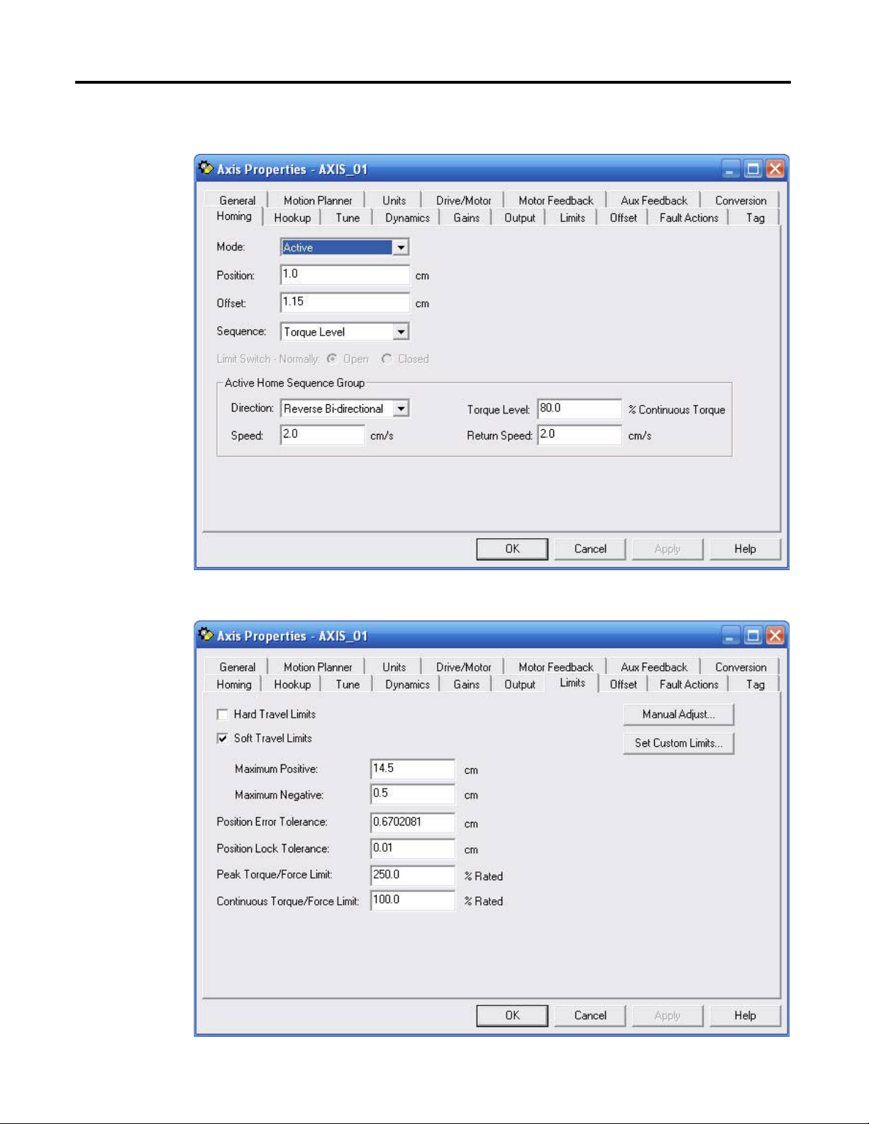
Appendix E Home to Torque-level Example
Figure 30 - Axis Properties - Homing Tab
Figure 31 - Axis Properties - Limits Tab
96 Rockwell Automation Publication MP-UM001D-EN-P - September 2013
Page 97

Figure 32 - Ladder Code Example
0
1
2
3
Home to Torque-level Example Appendix E
Rockwell Automation Publication MP-UM001D-EN-P - September 2013 97
Page 98
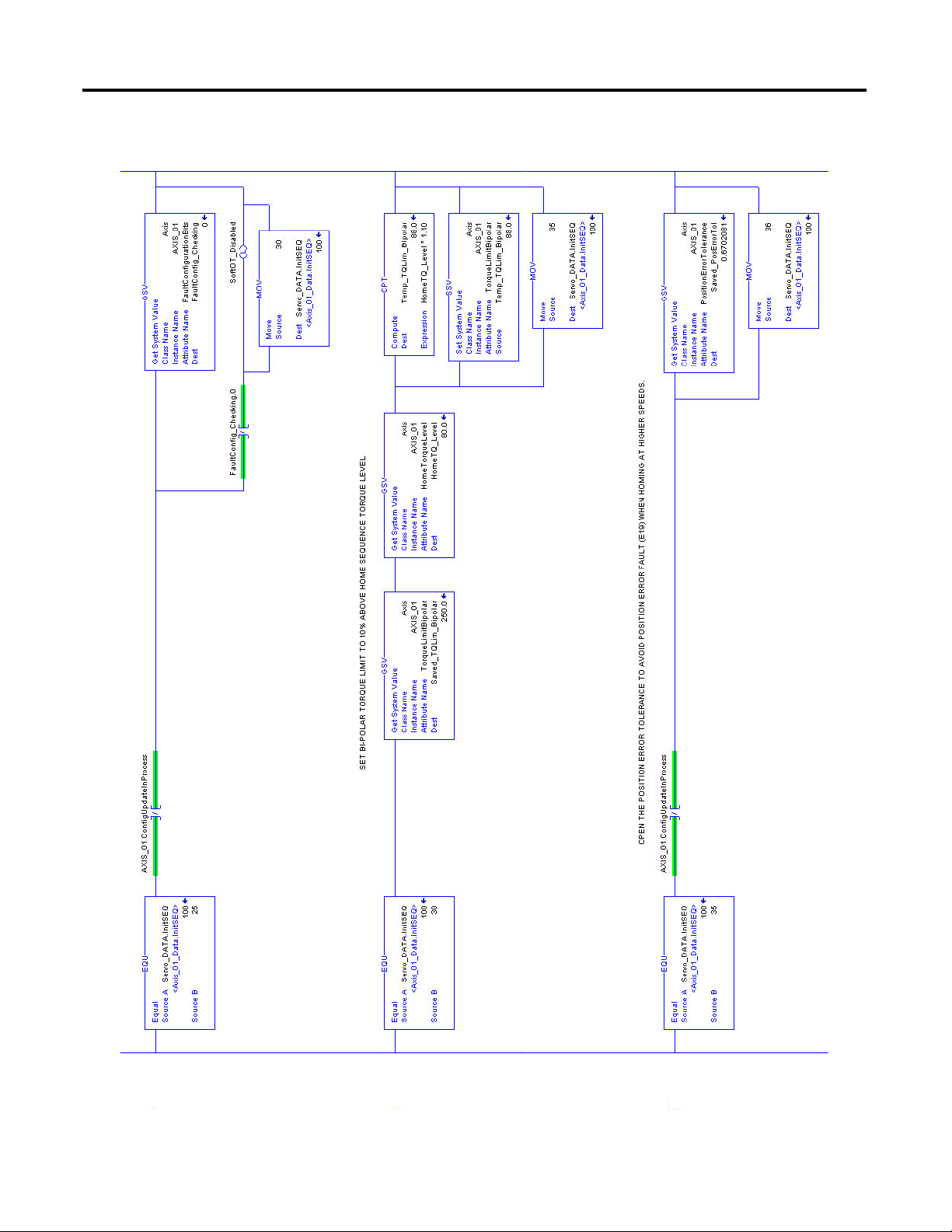
Appendix E Home to Torque-level Example
4
5
6
Figure 33 - Ladder Code Example, continued
98 Rockwell Automation Publication MP-UM001D-EN-P - September 2013
Page 99
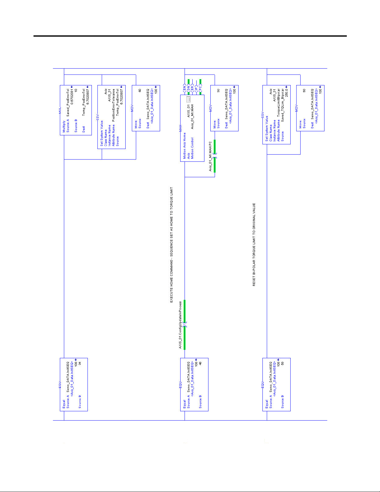
Figure 34 - Ladder Code Example, continued
7
8
9
Home to Torque-level Example Appendix E
Rockwell Automation Publication MP-UM001D-EN-P - September 2013 99
Page 100
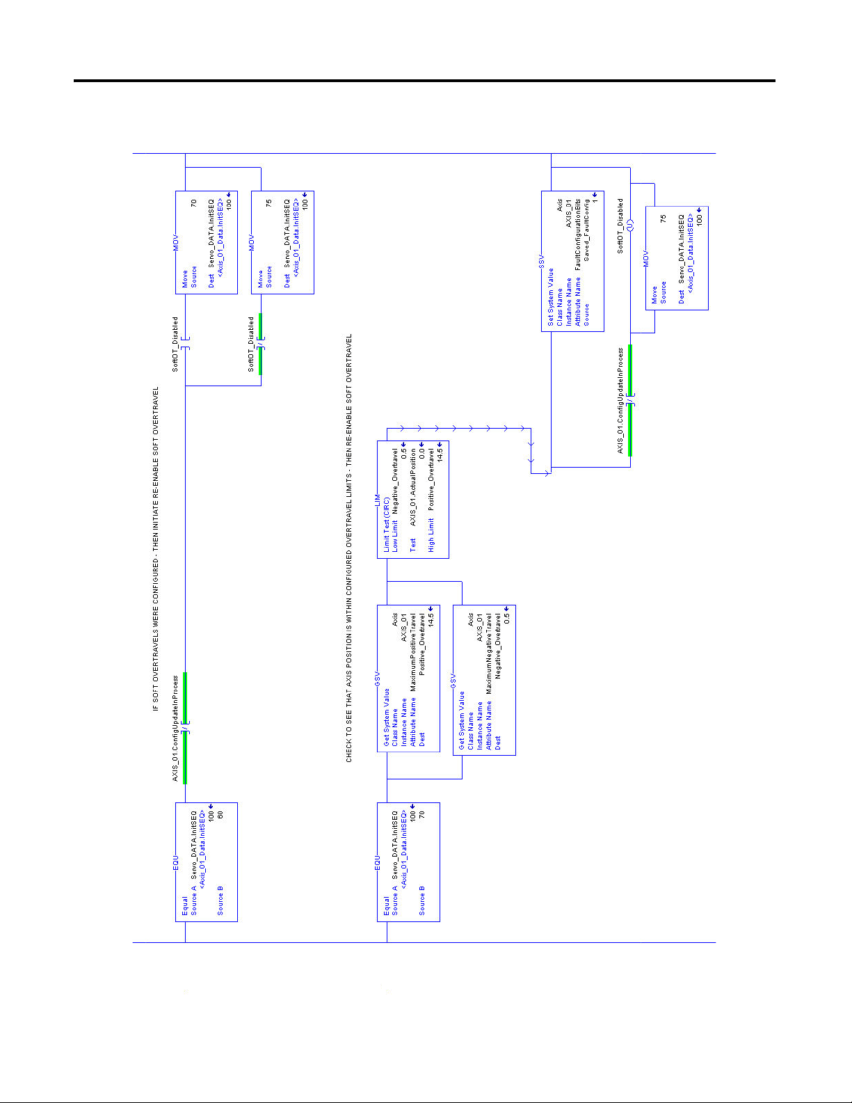
Appendix E Home to Torque-level Example
10
11
Figure 35 - Ladder Code Example, continued
100 Rockwell Automation Publication MP-UM001D-EN-P - September 2013
 Loading...