

Page 1

AllenBradley
Classic 1785 PLC5
Programmable
User
Controllers
(1785LT,
L
T2, LT3, L
Manual
T4)
Page 2

Important User Information
Because of the variety of uses for the products described in this
publication, those responsible for the application and use of this control
equipment must satisfy themselves that all necessary steps have been
taken to assure that each application and use meets all performance and
safety requirements, including any applicable laws, regulations, codes,
and standards.
The illustrations, charts, sample programs, and layout examples shown in
this guide are intended solely for purposes of example. Since there are
many variables and requirements associated with any particular
installation, Allen-Bradley does not assume responsibility or liability
(to include intellectual property liability) for actual use based on the
examples shown in this publication.
Allen-Bradley publication SGI-1.1, Safety Guidelines for the Application,
Installation, and Maintenance of Solid State Control (available from your
local Allen-Bradley office), describes some important differences between
solid-state equipment and electromechanical devices that should be taken
into consideration when applying products such as those described in
this publication.
Reproduction of the contents of this copyrighted publication, in whole
or in part, without written permission of Allen-Bradley Company, Inc.,
is prohibited.
Throughout this manual we use notes to make you aware of
safety considerations:
ATTENTION: Identifies information about practices or
circumstances that can lead to personal injury or death,
property damage, or economic loss.
Attention statements help you to:
identify a hazard
avoid the hazard
recognize the consequences
Important: Identifies information that is critical for successful application
and understanding of the product.
Page 3

Summary of Changes
Summary of Changes
This manual has been revised to cover only Classic PLC-5 programmable
controllers: PLC-5/10, -5/12, -5/15, and -5/25.
It has also been revised to include the accompanying design worksheets
that were formerly available as a separate publication: 1785-5.2. This
separate publication is no longer available; see Appendix B for these
worksheets.
For information about Enhanced and Ethernet PLC-5 processors, see the
Enhanced and Ethernet PLC-5 Programmable Controllers User Manual,
publication 1785-6.5.12.
i
Page 4

Table of Contents
Summary of Changes
Classic PLC5 Programmable Controllers
Purpose
Manual Organization
How to Use this Manual
of this Manual
. . . . . . . . . . . . . . . . . . . . . . . . . . . .
. . . . . . . . . . . . .
. . . . . . . . . . . . . . . . . . . . . . . . . . . . . . . .
. . . . . . . . . . . . . . . . . . . . . . . . . . . . . . . . .
. . . . . . . . . . . . . . . . . . . . . . . . . . . . . . .
Understanding Your System 11. . . . . . . . . . . . . . . . . . . . . . .
Using this Chapter 11. . . . . . . . . . . . . . . . . . . . . . . . . . . . . . . . . . .
Understanding the Terms Used in this Chapter 11
Designing Systems 12
Preparing Your Functional Specification 13
Introducing Classic PLC5 Processor Modules 15
Using the Classic PLC5 Processor as a Remote I/O Scanner 18
Using the Classic PLC5 Processor as a Remote I/O Adapter 19
. . . . . . . . . . . . . . . . . . . . . . . . . . . . . . . . . .
. . . . . . . . . . . . . . .
. . . . . . . . . . . . . . . . . . . .
. . . . . . . . . . . . . . .
. . . .
. . . .
Choosing Hardware 21. . . . . . . . . . . . . . . . . . . . . . . . . . . . . .
Chapter
Selecting
Selecting I/O Adapter Modules 24
Selecting
Selecting an Operator Interface 26
Choosing a Classic PLC5 Processor for Your Application 29
Selecting Power Supplies 29
Selecting Memory Modules 213
Selecting a Replacement Battery 213
Selecting
Selecting a PLC5 Processor Backup System 214
Selecting Link Terminators 215
Connecting a Programming Terminal to a Processor Module 215
Choosing Cables 215
Objectives
I/O Modules
I/O Chassis
Complementary I/O
. . . . . . . . . . . . . . . . . . . . . . . . . . . . . . . . . . . .
21. . . . . . . . . . . . . . . . . . . . . . . . . . . . . . . . . . .
21. . . . . . . . . . . . . . . . . . . . . . . . . . . . . . . . .
. . . . . . . . . . . . . . . . . . . . . . . . . .
26. . . . . . . . . . . . . . . . . . . . . . . . . . . . . . . . .
. . . . . . . . . . . . . . . . . . . . . . . . . .
. . . . . . .
. . . . . . . . . . . . . . . . . . . . . . . . . . . . . .
. . . . . . . . . . . . . . . . . . . . . . . . . . . . .
. . . . . . . . . . . . . . . . . . . . . . . . .
213. . . . . . . . . . . . . . . . . . . . . . . . . . .
. . . . . . . . . . . . . . .
. . . . . . . . . . . . . . . . . . . . . . . . . . . . .
. . . . .
iii
iii
iv
iv
i
Placing System Hardware 31. . . . . . . . . . . . . . . . . . . . . . . . .
Chapter
Determining the Proper Environment 31
Protecting Your Processor 34
Avoiding Electrostatic Damage 34
Laying
Planning
Laying Out the Backpanel Spacing 36
Grounding
Objectives
. . . . . . . . . . . . . . . . . . . . . .
. . . . . . . . . . . . . . . . . . . . . . . . . . . . .
. . . . . . . . . . . . . . . . . . . . . . . . . .
Out Y
our Cable Raceway 34. . . . . . . . . . . . . . . . . . . . . . . . .
Cabling
. . . . . . . . . . . . . . . . . . . . . . .
Configuration
31. . . . . . . . . . . . . . . . . . . . . . . . . . . . . . . . . . .
35. . . . . . . . . . . . . . . . . . . . . . . . . . . . . . . . . . . .
37. . . . . . . . . . . . . . . . . . . . . . . . . . . . . . .
Page 5

Table of Contentsii
Assigning Addressing Modes, Racks, and Groups 41. . . . . .
Chapter
Placing
Understanding the Terms Used in this Chapter 42
Choosing the Addressing Mode 43
Assigning Racks 49
Addressing
Choosing
Chapter
Identifying Classic PLC5 Processor Channels/Connectors 51
Configuring
Configuring a DH+ Link 53
Connecting a DH+ Link to Data Highway 510
Choosing Programming Terminal Connection 510
Objectives
I/O Modules in Chassis
. . . . . . . . . . . . . . . . . . . . . . . . . . . . . . . . . . . .
Complementary I/O
Communication
Objectives
Communication for Y
. . . . . . . . . . . . . . . . . . . . . . . . . . . . . . . .
41. . . . . . . . . . . . . . . . . . . . . . . . . . . . . . . . . . .
41. . . . . . . . . . . . . . . . . . . . . . . . . .
. . . . . . . . . . . . . . .
. . . . . . . . . . . . . . . . . . . . . . . . . .
412. . . . . . . . . . . . . . . . . . . . . . . . . .
51. . . . . . . . . . . . . . . . . . . . . . . . .
51. . . . . . . . . . . . . . . . . . . . . . . . . . . . . . . . . . .
. . . . . .
our Processor 53. . . . . . . . . . . . . .
. . . . . . . . . . . . . . . . . . .
. . . . . . . . . . . . . . . .
Planning Your System Programs 61. . . . . . . . . . . . . . . . . . . .
Chapter
Planning Application Programs 61
Using SFCs with PLC5 Processors 61
Preparing the Programs for Your Application 63
Addressing Data T
Using the Processor Status File 69
Objectives
able Files
61. . . . . . . . . . . . . . . . . . . . . . . . . . . . . . . . . . .
. . . . . . . . . . . . . . . . . . . . . . . . . .
. . . . . . . . . . . . . . . . . . . . . . .
. . . . . . . . . . . . . . . .
67. . . . . . . . . . . . . . . . . . . . . . . . . . . .
. . . . . . . . . . . . . . . . . . . . . . . . . .
Selecting Interrupt Routines 71. . . . . . . . . . . . . . . . . . . . . . .
Chapter
Using Programming Features 71
Writing
Understanding ProcessorDetected Major Faults 711
Objectives
a Fault Routine
71. . . . . . . . . . . . . . . . . . . . . . . . . . . . . . . . . . .
. . . . . . . . . . . . . . . . . . . . . . . . . . .
73. . . . . . . . . . . . . . . . . . . . . . . . . . . . . . . .
. . . . . . . . . . . . .
Transferring Discrete and BlockTransfer Data 81. . . . . . . . .
Chapter
Transferring Data Using Adapter Mode 81
Programming Discrete Transfer in Adapter Mode 84
Programming Block Transfer in Adapter Mode 87
Transferring Data Using Scanner Mode 816
Programming Discrete Transfer in Scanner Mode 816
Programming Block Transfer in Scanner Mode 817
Programming Considerations 821
Objectives
81. . . . . . . . . . . . . . . . . . . . . . . . . . . . . . . . . . .
. . . . . . . . . . . . . . . . . . . .
. . . . . . . . . . . . .
. . . . . . . . . . . . . . .
. . . . . . . . . . . . . . . . . . . .
. . . . . . . . . . . . .
. . . . . . . . . . . . . . .
. . . . . . . . . . . . . . . . . . . . . . . . . . .
Page 6

Table of Contents iii
Calculating
Chapter
Introduction to Classic PLC5 Processor Scanning 91
I/O ScanningDiscrete and Block Transfer 95
Instruction Timing and Memory Requirements 97
Program Constants 913
Direct and Indirect Elements 913
Program T
Objectives
iming 91. . . . . . . . . . . . . . . . . . . . . . . .
91. . . . . . . . . . . . . . . . . . . . . . . . . . . . . . . . . . .
. . . . . . . . . . . .
. . . . . . . . . . . . . . . . .
. . . . . . . . . . . . . . .
. . . . . . . . . . . . . . . . . . . . . . . . . . . . . . . . . .
. . . . . . . . . . . . . . . . . . . . . . . . . . . .
Maximizing System Performance 101. . . . . . . . . . . . . . . . . . . .
Chapter
Components of Throughput 101
Input and Output Modules Delay 101
I/O Backplane Transfer 102
Remote
Processor Time 106
Calculating Throughput 106
Objectives
I/O Scan T
. . . . . . . . . . . . . . . . . . . . . . . . . . . . . . . . . . . . .
101. . . . . . . . . . . . . . . . . . . . . . . . . . . . . . . . . . .
. . . . . . . . . . . . . . . . . . . . . . . . . . . . .
. . . . . . . . . . . . . . . . . . . . . . . . .
. . . . . . . . . . . . . . . . . . . . . . . . . . . . . . . .
ime 102. . . . . . . . . . . . . . . . . . . . . . . . . . . . . . . .
. . . . . . . . . . . . . . . . . . . . . . . . . . . . . . . .
Selecting Switch Settings A1. . . . . . . . . . . . . . . . . . . . . . . . .
Chassis Backplane with Classic PLC5 Processor A1. . . . . . . . . . . . .
Chassis Backplane with Adapter Module A2
Chassis Configuration Plug for Power Supply A3
Remote I/O Adapter Module 1771ASB Series C without
Complementary I/O
Remote I/O Adapter Module 1771ASB Series C with
Complementary I/O
SW1 A7
. . . . . . . . . . . . . . . . . . . . . . . . . . . . . . . . . . . . . . . . . . . . .
AdapterMode ProcessorsSW2 in a PLC5 or Scanner Module A8
AdapterMode ProcessorsSW2 in a PLC2/20, 2/30,
or Sub I/O Scanner Module System A9
AdapterMode ProcessorsSW2 in a PLC3 or PLC5/250
System with 8Word Groups A10
AdapterMode ProcessorsSW2 in a PLC3 or PLC5/250
System with 4Word Groups A11
SW3 A12
. . . . . . . . . . . . . . . . . . . . . . . . . . . . . . . . . . . . . . . . . . . . .
. . . . . . . . . . . . . . . . . . . . . . . . .
. . . . . . . . . . . . . . . . . . . . . . . . .
. . . . . . . . . . . . . . . . . . .
. . . . . . . . . . . . . . . .
A4. . . . . . . . . . . . . . . . . . . . . . . . . . . . . . . .
A6. . . . . . . . . . . . . . . . . . . . . . . . . . . . . . . .
. .
. . . . . . . . . . . . . . . . . . . .
Design Worksheets B1. . . . . . . . . . . . . . . . . . . . . . . . . . . . . .
Conventions Used in These Worksheets B1. . . . . . . . . . . . . . . . . . .
Prepare
Determine Control Strategy B4
Identify Chassis Locations B6
Select Module T
Total
Assign I/O Modules to Chassis and Assign Addresses B10
Select Adapter Modules B12
Place System Hardware B14
a Functional Specification
. . . . . . . . . . . . . . . . . . . . . . . . . . . . .
. . . . . . . . . . . . . . . . . . . . . . . . . . . . .
ypes and List I/O Points
I/O Module Requirements
. . . . . . . . . . . . . . . . . . . . . . . . . . . . . . .
. . . . . . . . . . . . . . . . . . . . . . . . . . . . . . .
B2. . . . . . . . . . . . . . . . . . . . . . . .
B7. . . . . . . . . . . . . . . . . . . .
B9. . . . . . . . . . . . . . . . . . . . . . . . . .
. . . . . . . . . .
Page 7

Table of Contentsiv
Configure
Determine Communication Requirements B17
Select a Classic PLC5 Processor B21
Select Power Supplies B23
Choose a Programming Terminal B24
Select Programming T
Select Operator Interface B26
Develop Programming Specifications B28
Switch Settings
erminal Configuration
B15. . . . . . . . . . . . . . . . . . . . . . . . . . . . . .
. . . . . . . . . . . . . . . . . . .
. . . . . . . . . . . . . . . . . . . . . . . .
. . . . . . . . . . . . . . . . . . . . . . . . . . . . . . . .
. . . . . . . . . . . . . . . . . . . . . . . . .
B25. . . . . . . . . . . . . . . . .
. . . . . . . . . . . . . . . . . . . . . . . . . . . . . .
. . . . . . . . . . . . . . . . . . . . . .
Page 8
Preface
Classic PLC5 Programmable Controllers
How to Use
Your Documentation
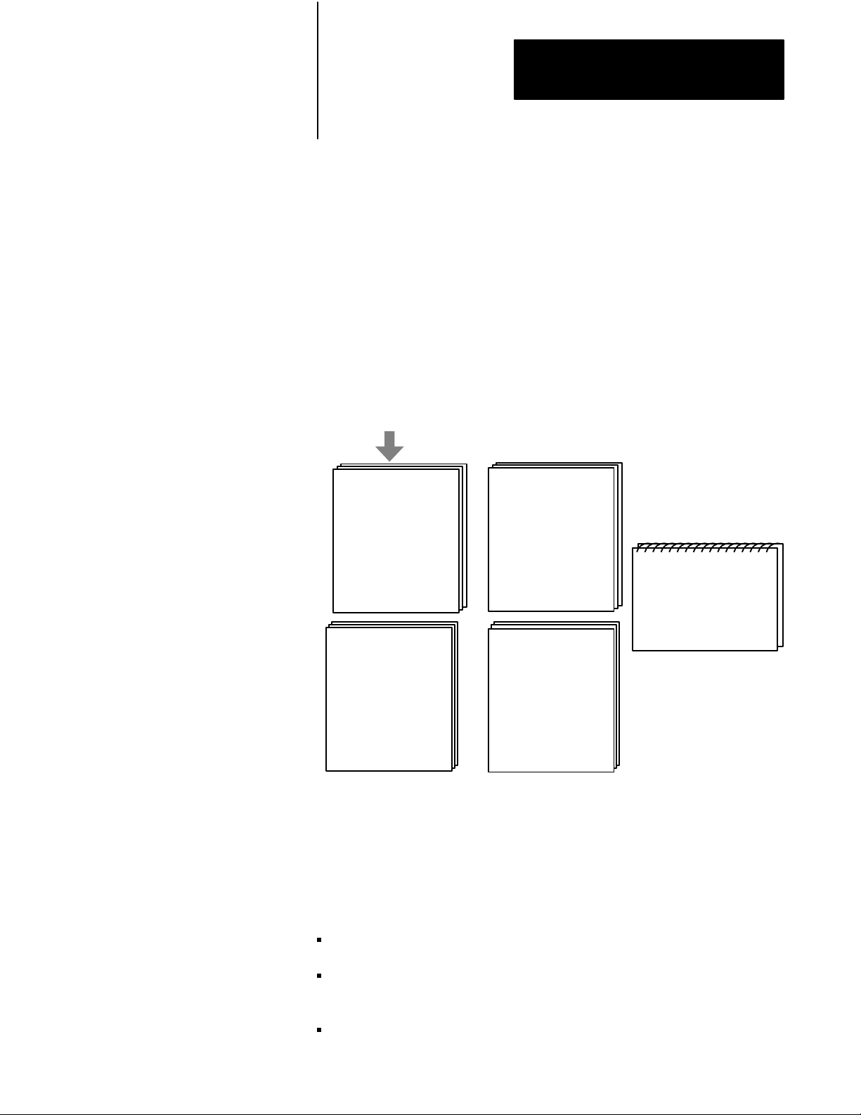
Your Classic PLC-5 Programmable Controllers documentation is organized
into manuals according to the tasks you perform. This organization lets
you easily find the information you want without reading through
information that is not related to your current task. The arrow in Figure 1
points to the book you are currently using.
Figure 1
Classic
PLC5 Programmable Controllers Documentation Library
Classic 1785 PLC5
Programmable Controllers
User Manual
Explanation of processor
functionality, system
design, and programming
considerations and worksheets
17856.2.1
6200 or AI Series Software
Classic 1785 PLC5
Programmable Controllers
Hardware Installation
How to install and set
switches for chassis,
PLC5 processor, how
to wire and ground
your system
17856.6.1
Instruction Set
Reference
Instruction execution,
parameters, status
bits and examples
1785 PLC5
Programmable Controllers
Quick Reference
Quick access to switches,
status bits, indicators,
instructions, SW screens
17857.1
Purpose
of this Manual
17856.1
For more information on 1785 PLC-5 programmable controllers or the
above publications, contact your local Allen-Bradley sales office,
distributor, or system integrator.
This manual is intended to help you design a Classic PLC-5 programmable
controller system. Use this manual to assist you in:
selecting the proper hardware components for your system
determining the important features of classic PLC-5 processors and how
to use those features
planning your classic PLC-5 system layout
iii
Page 9

Preface
Manual Organization
Chapter
/
Appendix
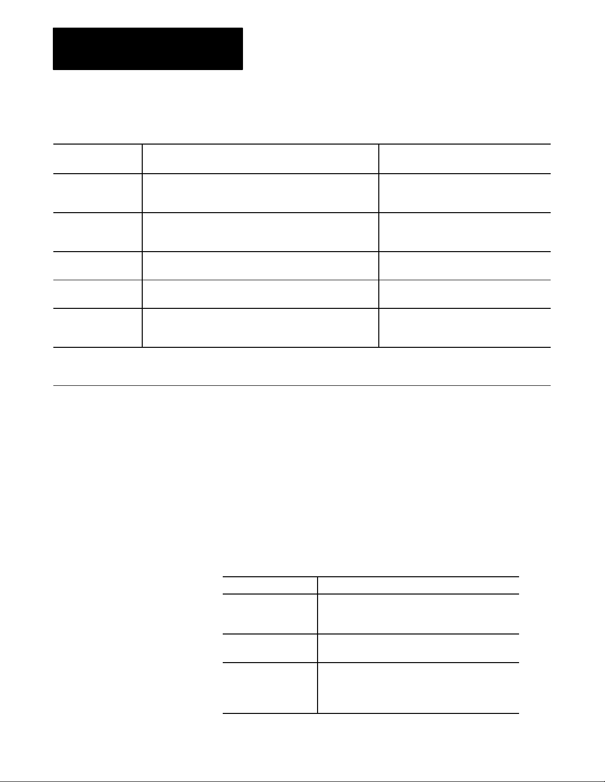
1 Understanding Your System Provides an overview of Classic PLC5 processors in different system configurations. Provides
2 Choosing Hardware Provides information on your hardware choices when you design a Classic PLC5 processor
3 Placing System Hardware Describes proper environment, Classic PLC5 processor protection, and prevention of
4 Assigning Addressing Mode,
Rack, and Groups
5 Choosing Communication Identifies each Classic 5 processor channel/connector, and explains how to configure your
6 Planning Your System Programs Explains the use of sequential function charts (SFCs). Provides guidelines and examples for
This manual has ten chapters and two appendices. The following table
lists each chapter or appendix with its corresponding title and a brief
overview of the topics covered in it.
Title Topics Covered
an introduction to Classic PLC5 processors and their primary features and configurations. Also
provides information on using a Classic PLC5 processor as a remote I/O scanner or a remote
I/O adapter.
system.
electrostatic damage for your Classic PLC5 programmable controller system. Also covers
raceway and cable layout, backpanel spacing, and grounding configurations.
Describes the I/O addressing modes that you can choose for your chassis. Explains how you
assign group and rack numbers to your I/O chassis. Also covers how you configure
complementary I/O by assigning rack and group addresses.
Classic PLC5 processor. Provides additional information about the Data Highway Plust
(DH+t) link, programming software, and programmingterminal connections.
preparing system programs. Provides a map of data table files and methods to address the
data table files. Explains how to use the processor status file.
7 Selecting Interrupt Routines Summarizes the conditions for which you would choose fault routines for your application.
Provides a definition of fault routines.
8 Transferring Discrete and
BlockTransfer Data
9 Calculating Program Timing Provides an overview of processor scan timing. Lists execution times and memory
10 Maximizing System Performance Explains how to calculate throughput, and provides methods for optimizing I/O scan time.
A Selecting Switch Settings Describes the switch settings for configuring a Classic PLC5 programmable controller system.
B Design Worksheets Provides worksheets to help the designer plan the system and the installer to install the system.
How to Use this Manual
Explains how your CLassic PLC5 processor transfers discrete and blocktransfer data in both
scanner and adapter modes.
requirements for bit and word instructions as well as file instructions.
The following flow chart demonstrates a thought process that you can use
when you plan your Classic PLC-5 programmable controller system.
iv
Page 10
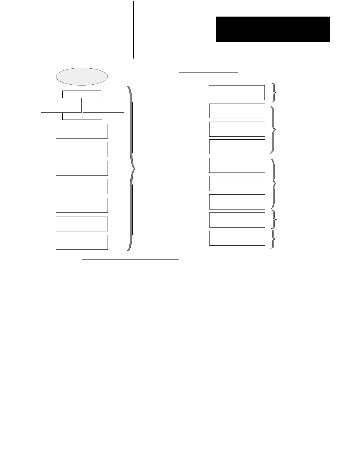
System Design
Determined
Select I/O
modules, terminals
Place
hardware
Preface
Assign
addressing
Configure processor
communication
Assigning
Addressing Mode,
Racks, and Groups
Select adapter modules
Select I/O chassis
Select power supply
Select PLC5 processor
Select batteries and
memory modules
Complementary I/O
selected?
Backup system
selected?
Choosing
Hardware
and
Placing
System
Hardware
Configure Data
Highway Plus
Select programming
software
Design SFCs
Data table layout and
processor status
Use fault routines
Transfer data in adapter
and scanner modes
I/O update and ladder
program scan times
Choosing
Communication
Planning Your
System Programs
Transferring
Discrete and
Block Data
Calculating
Program Timing
and Maximizing
System
Performance
Since your decisions cannot always be made as a part of a strictly linear
process, you can choose to complete tasks in parallel. When you select
your I/O modules, for example, you can also begin to lay out and address
your modules. Consult chapter 3, “Placing System Hardware,” to
determine environmental requirements, enclosures needed, cable layout,
and grounding requirements for your chassis and I/O links. Also, you can
choose to assess block-transfer timing when you determine where you will
place your block-transfer modules (in the processor-resident local I/O
chassis, extended-local I/O chassis, or remote I/O chassis).
v
Page 11

Chapter
Understanding Your System
1
Using this Chapter
Understanding the Terms
Used in this Chapter
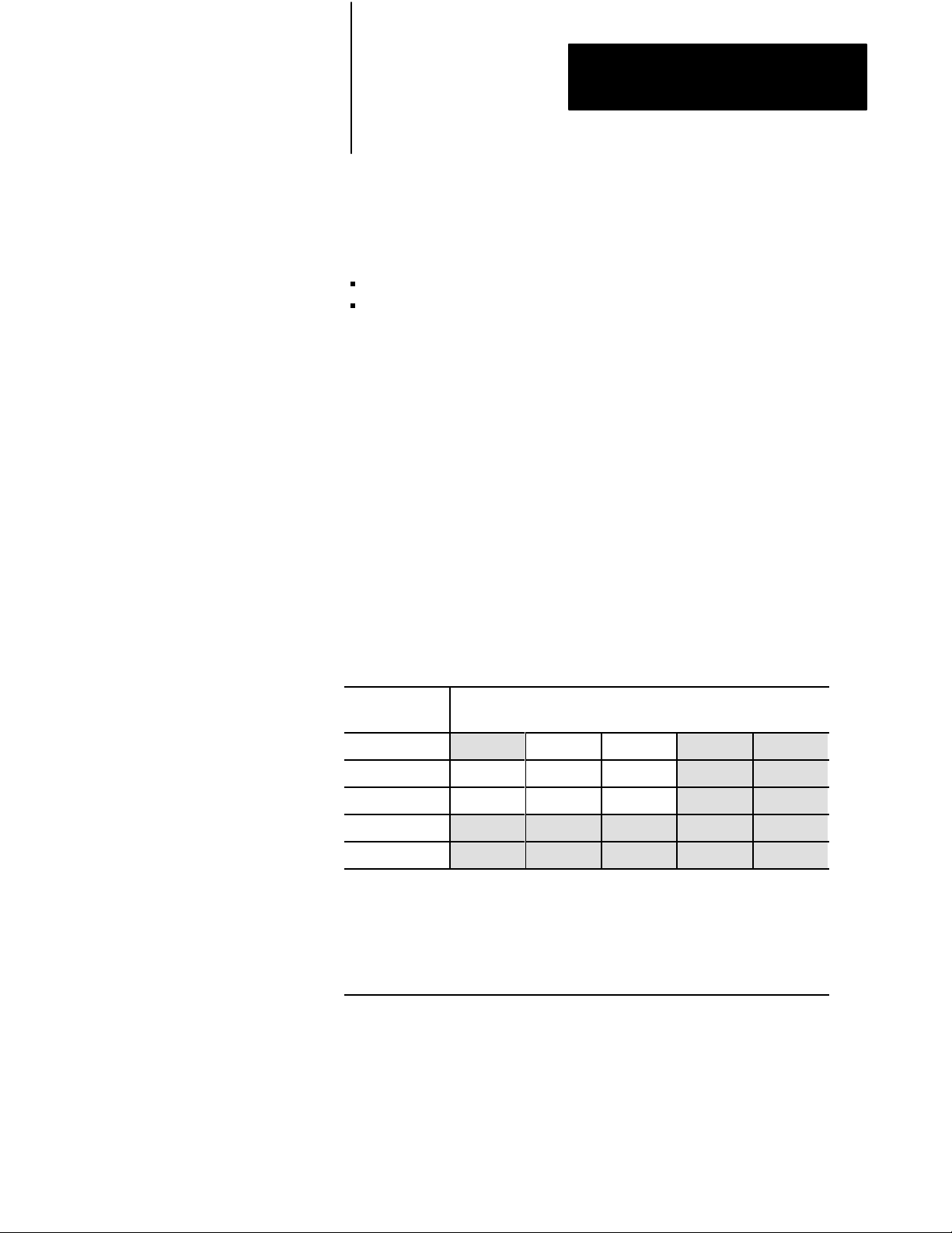
If you want to read about: Go to page:
Terms used in this chapter 11
Designing systems 12
Preparing your functional specification 13
Identifying Classic PLC5 processor features 15
Using the Classic PLC5 processor as a remote I/O scanner 18
Using the Classic PLC5 processor as a remote I/O adapter 19
Become familiar with the following terms and their definitions.
Term Definition
Processorresident
local I/O chassis
Processorresident
local I/O
Remote I/O link a serial communication link between a PLC5 processor port in scanner
the I/O chassis in which the PLC5 processor is installed
I/O modules located in the same chassis as the PLC5 processor
mode and an adapter as well as I/O modules that are located remotely
from the PLC5 processor
Remote I/O chassis the hardware enclosure that contains an adapter and I/O modules that
are located remotely on a serial communication link to a PLC5
processor in scanner mode
Discretetransfer data data (words) transferred to/from a discrete I/O module
Blocktransfer data data transferred, in blocks of data up to 64 words, to/from a block
transfer I/O module (for example, an analog module)
1-1
Page 12
Chapter 1
Understanding Your System
Designing
Centralized
Systems
control
is a
hierarchical system where control
over an entire process is
concentrated in one processor
Distributed
control
is a system in
which control and management
functions are spread throughout a
plant. Multiple processors handle
the control and management
functions and use a Data
Highway
or a bus system
for communication.
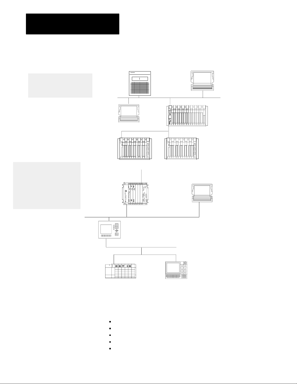
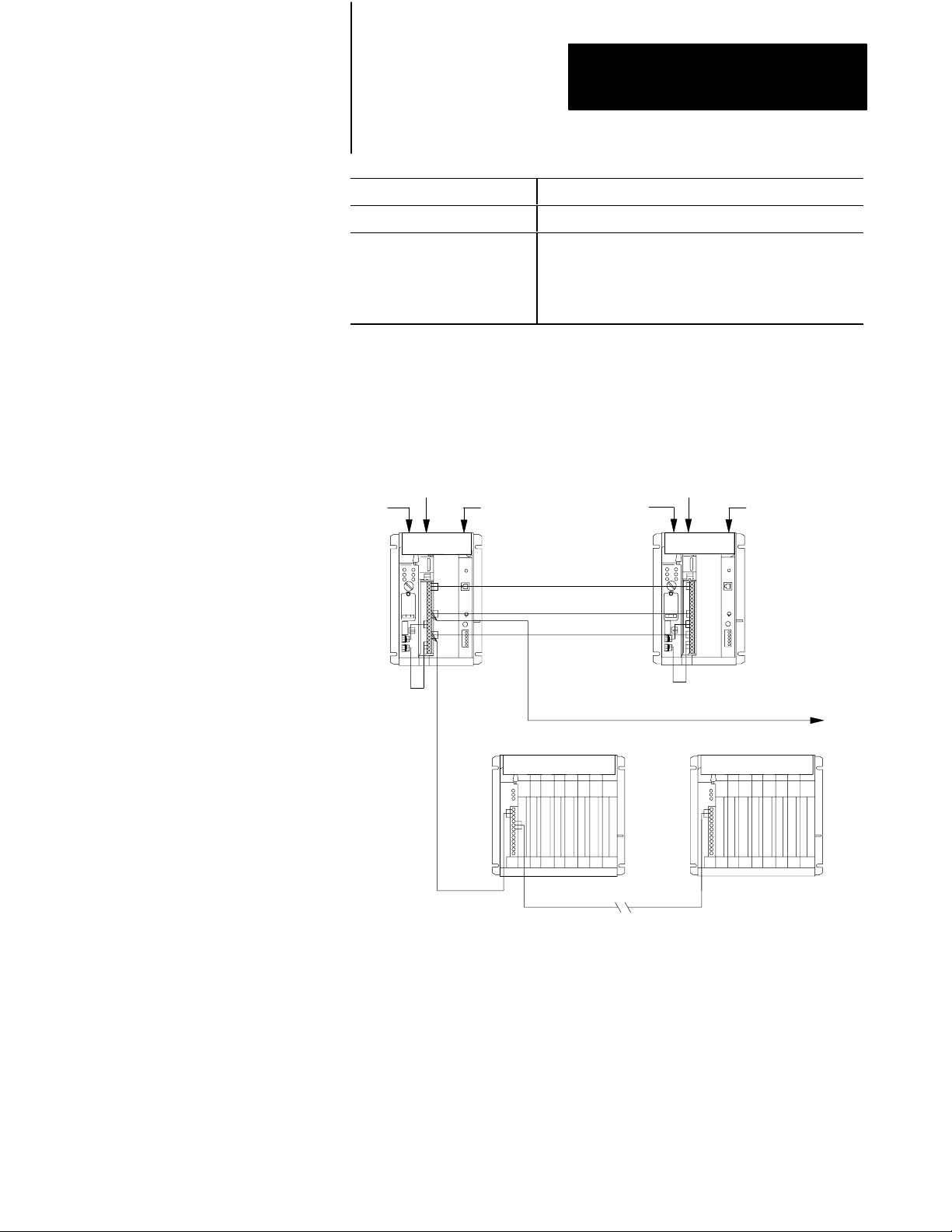
You can use Classic PLC-5 processors in a system that is designed for
centralized control or in a system that is designed for distributed control.
HP 9000
or VAX
Host
.
Programming
Terminal with
ControlView
Software
Remote I/O Link
Chassis with Chassis with
1771ASB
Remote I/O
Adapter
r
6200 VMS
INTERCHANGE
Software
Pyramid
Integrator
To DECnet
DH+ Link
Classic PLC5
Processor
1771ASB
Remote I/O
Adapter
Programming
Terminal
Programming Terminal
ControlView
INTERCHANGE
Software
DH+ Link
PanelView
Operator
Terminal
SLC 5/01 Processor
7slot Modular System
with 1747DCM Module
Remote I/O Link
Series 8600
CNC with
Remote I/O
Consider the following items as general guidelines when designing
your system.
Will your processor(s) be used in a centralized or distributed system?
What type of process(es) will be controlled by the PLC-5 system?
What processes will be controlled together?
What are the environmental and safety concerns?
What is the flow and functionality of your system?
18084
1-2
Page 13
System Design
Determined
Select I/O
modules, terminals
Place
hardware
Chapter 1
Understanding Your System
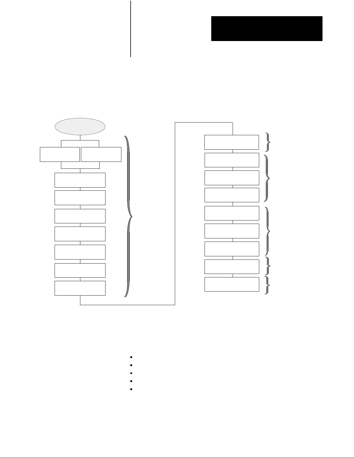
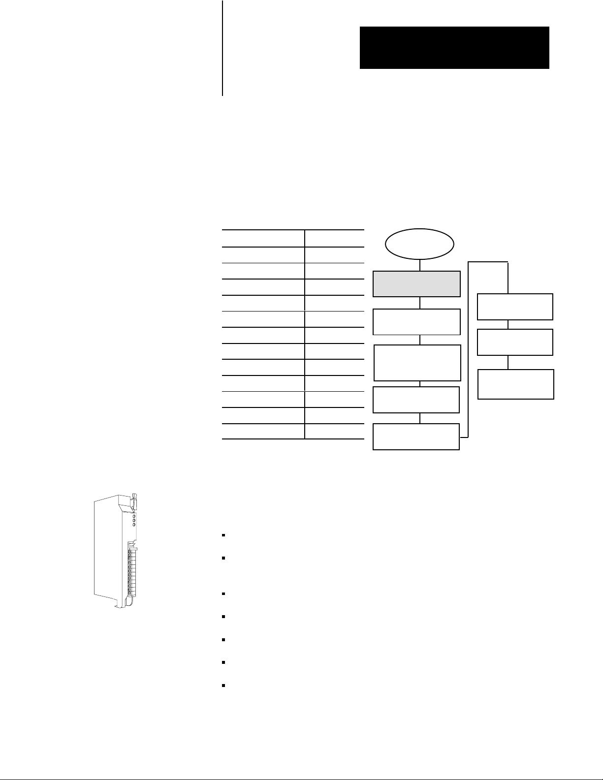
Determine the general criteria for your system. Use the chapters that
follow to guide you through the criteria and choices for selecting the major
Classic PLC-5 programmable controller system elements, as shown in
Figure 1.1.
Figure 1.1
Processor System Design Flow
PLC5
Assign
addressing
Configure processor
communication
Assigning
Addressing Mode,
Racks, and Groups
Select adapter modules
Select I/O chassis
Select power supply
Select Classic PLC5
processor
Select batteries and
memory modules
Complementary I/O
selected?
Backup system
selected?
Preparing Your
Functional Specification
Choosing
Hardware
and
Placing
System
Hardware
Configure Data
Highway Plus
Select programming
software
Design SFCs
Data table layout and
processor status
Use fault routines
Transfer data in adapter
and scanner modes
I/O update and ladder
program scan times
Choosing
Communication
Planning Your
System Programs
Transferring
Discrete and
Block Data
Calculating
Program Timing
and Maximizing
System
Performance
We recommend that you first develop a specification that defines your
hardware selection and your programming application. The specification
is a conceptual view of your system. Use it to determine your:
control strategy
hardware selection, layout, and addressing
sequential function chart (SFC)
special programming features
ladder-logic requirements
1-3
Page 14

Chapter 1
Understanding Your System
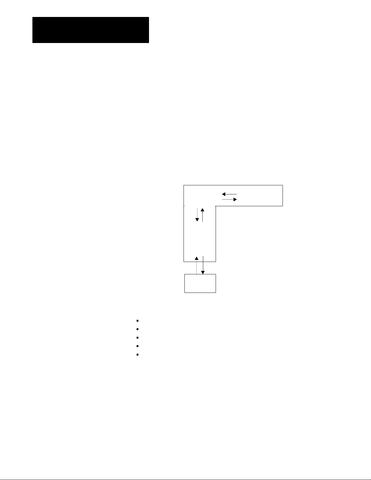
Figure 1.2 illustrates a program-development model that you can use.
Figure 1.2
ProgramDevelopment
Functional
Specification
(General Conception)
Model
Acceptance
Signoff
Detailed
Anaylsis
Program
Development
Testing
This model allows for the interaction of activities at the different levels.
Each section represents an activity that you perform. Prepare a functional
specification to start; then, prepare the detailed analysis.
Based on the detailed analysis, you can also develop your programs, enter
your programs, and test them. When testing is complete, you are ready to
implement the programs in your application. The detailed analysis can be
used as the basis for developing your testing procedures and requirements.
Because the functional specification is well thought out, it can be used as
the program sign-off document.
Functional Specification Content
1-4
The functional specification represents a very general view of your process
or a description of operation. Identify the events and the overall order in
which they must occur. Identify the equipment that you will need for your
process/operation. Generally indicate the layout of your system. If your
application requires a distributed control system, for example, indicate
where you will need remote I/O links. Also, you can have a process that is
located close to your processor. The process can require faster update time
than that provided by a remote I/O link, so you can select an extendedlocal I/O link for that process.
Important: Choose a communication rate for your remote I/O link at
which every device on the link can communicate.
Page 15

Chapter 1
Understanding Your System
The program-development portion of your functional specification can be
in any form: written statement; flowchart; or rough-draft MCPs, SFCs,
and subroutines. Use the form that is most familiar to you. We
recommend, however, that you generate rough-draft SFCs and subroutines
so that you have a better correspondence between your beginning diagrams
and your finished program.
Detailed Analysis
In this phase, you identify the logic needed to plan your programs. This
includes inputs, outputs, specific actions, and transitions between actions
(i.e., the bit-level details needed to write your program).
Program Development
Introducing
Classic PLC5
Processor Modules
You enter the programs either offline into your computer or online into a
processor. In the next phase, you test the programs that you have entered.
Once testing is complete, your resulting programs should match your
functional specification.
Checking for Completeness
When you complete the functional specification and the detailed analysis,
review them and check for missing or incomplete information such as:
input conditions
safety conditions
startup or emergency shutdown routines
alarms and alarm handling
fault detection and fault handling
message display of fault conditions
abnormal operating conditions
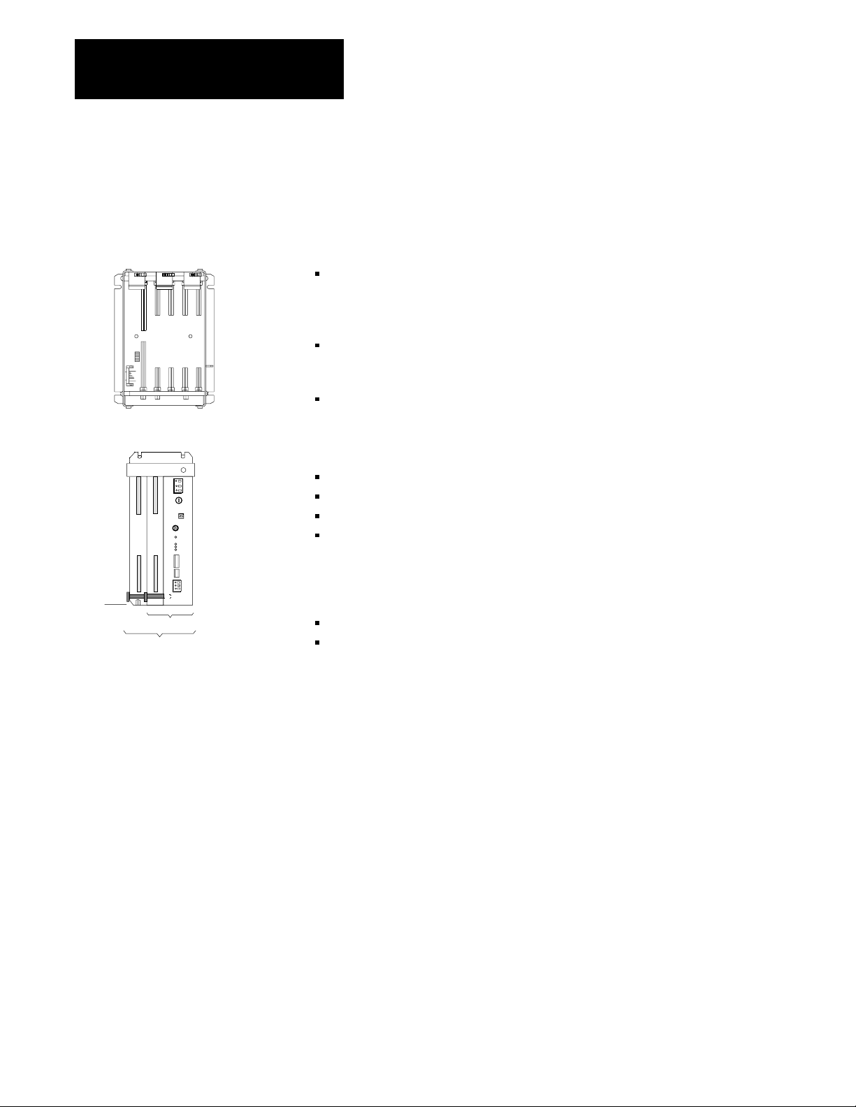
The following is a list of the PLC-5 processors and their catalog numbers.
Processor Catalog Number
PLC5/10t
PLC5/12t
PLC5/15t
PLC5/25t
1785LT4
1785LT3
1785LT
1785LT2
For information on other PLC-5 processors (Enhanced, Ethernet, or
ControlNet), see your Allen-Bradley representative.
1-5
Page 16

Chapter 1
Understanding Your System
Classic PLC5 Family Processor Features
From the family of PLC-5 processors, you can choose the processor(s)
that you need for your application. Features common to all Classic PLC-5
processors are:
same physical dimensions
use of the left-most slot in the 1771 I/O chassis
can use any 1771 I/O module in the processor-resident local I/O chassis
with up to 32 points per module
same programming software and programming terminals
same base set of instructions
ladder programs and SFCs can be used by any of the PLC-5 processors
Check with your Allen-Bradley sales office or distributor if you have
questions regarding any of the features of your PLC-5 processor.
Subprogram Calls
Use a subroutine to store recurring sections of program logic that can be
accessed from multiple program files. A subroutine saves memory
because you program repetitive logic only once. The JSR instruction
directs the processor to go to a separate subroutine file within the logic
processor, scan that subroutine file once, and return to the point
of departure.
For detailed information about how you generate and use subroutines, see
your programming software documentation set.
Sequential Function Charts
Use SFCs as a sequence-control language to control and display the state
of a control process. Instead of one long ladder program for your
application, divide the logic into steps and transitions. A step corresponds
to a control task; a transition corresponds to a condition that must occur
before the programmable controller can perform the next control task. The
display of these steps and transitions lets you see what state the machine
process is in at a given time.
1-6
For detailed information about how you generate and use SFCs, see you
programming software.
Ladder Logic Programs
A main program file can be an SFC file numbered 1-999; it can also be a
ladder-logic file program numbered 2-999 in any program file.
Page 17
Chapter 1
Understanding Your System
Consider using this technique:
SFC
Ladder Logic
If you are:
• defining the order of events in a sequential process
• more familiar with ladder logic than with programming
languages such as BASIC
• performing diagnostics
• programming discrete control
For detailed information about how you use ladder logic, see your
programming software documentation.
Backup System
The following diagram shows a typical PLC-5 backup system:
Local I/O Chassis
1785BCM Module
PLC5
Processor
1771P4S
Power Supply
HSSL
DH+ Link
Remote I/O Link
Local I/O Chassis
1785BCM Module
PLC5
Processor
1771P4S
Power Supply
DH+ LInk
Remote I/O Chassis Remote I/O Chassis
Remote I/O Link
18691
In a PLC-5 backup system configuration, one system controls the operation
of remote I/O and DH+ communications. This system is referred to as the
“primary system.” The other system is ready to take control of the remote
I/O and DH+ communications in the event of a fault in the primary system.
This is referred to as the “secondary system.”
See chapter 2, “Choosing Hardware,” to select backup system hardware.
See the PLC-5 Backup Communication Module User Manual, publication
1785-6.5.4, for more information on configuring a PLC-5 backup system.
1-7
Page 18
Chapter 1
Understanding Your System
Using the Classic PLC5
Processor as a Remote I/O
Scanner
Use scanner mode whenever you want a Classic PLC-5 processor to scan
and control remote I/O link(s). The scanner-mode processor also acts as a
supervisory processor for other processors that are in adapter mode.
The scanner-mode processor scans the processor memory file to read
inputs and control outputs. The scanner-mode processor transfers
discrete-transfer data and block-transfer data to/from the processor-resident
local rack as well as to/from modules in remote I/O racks.
A PLC-5 processor scans processor-resident local I/O synchronously to the
program scan. A PLC-5 processor scans remote I/O asynchronously to the
program scan, but the processor updates the input/output image data table
from the remote I/O buffer(s) synchronously to the program scan. This
occurs at the end of each program scan.
ProcessorResident
Local I/O Scan
Synchronous to
Program Scan
ScannerMode
PLC5
Processor
Input
Output
Remote
I/O
Buffer
Input
Output
Processor
Resident
I/O
Remote I/O
Scan
Asynchronous to
Program Scan
OutputInput
Remote I/O
Link
The scanner-mode PLC-5 processor can also:
gather data from node adapter devices in remote I/O racks
process I/O data from 8-, 16-, or 32-point I/O modules
address I/O in 2-, 1-, or 1/2-slot I/O groups
support a complementary I/O configuration
support block transfer in any I/O chassis
Configure the PLC-5/15 or -5/25 processor for scanner mode by setting
switch assembly SW1.
1-8
Page 19
Chapter 1
Understanding Your System
Using the Classic PLC5
Processor
as a Remote I/O Adapter
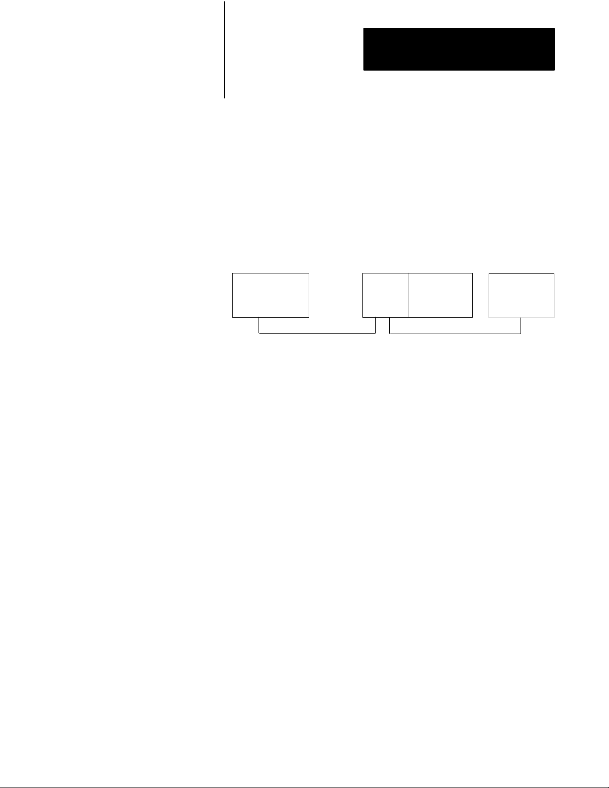
Use a Classic PLC-5 processor (except the PLC-5/10 processor) in adapter
mode when you need predictable, real-time exchange of data between a
distributed control PLC-5 processor and a supervisory processor. You
connect the processors via the remote I/O link (see Figure 1.3). You can
monitor status between the supervisory processor and the adapter-mode
PLC-5 processor at a consistent rate (i.e., the transmission rate of the
remote I/O link is unaffected by programming terminals and other
non-control-related communications).
Figure 1.3
AdapterMode
Supervisory
Processor
1
The following programmable controllers can operate as supervisory processors:
PLC2/20t and PLC2/30t processors
PLC3t and PLC3/10t processors
PLC5/11, 5/15, 5/20, 5/25, and 5/30 processors as well as PLC5/VMEt processors
PLC5/40, 5/40L, 5/60, 5/60L, and 5/80 processors as well as PLC5/40BVt and
PLC5/40LVt processors
PLC5/20Et, 5/40Et
PLC5/250t
2
All PLC5 family processors, except the PLC5/10, can operate as remote I/O adapter modules.
Communication
1
Remote I/O Link
PLC5
Processor
in Adapter
2
Mode
1771
I/O
Remote I/O Link
DL40
Message
Display
The PLC-5 processor in adapter mode acts as a remote station to the
supervisory processor. The adapter-mode PLC-5 processor can monitor
and control its processor-resident local I/O while communicating with the
supervisory processor via a remote I/O link.
The supervisory processor communicates with the PLC-5/12, -5/15, or
-5/25 adapter with either eight or four I/O image table words.
A PLC-5 processor transfers I/O data and status data using discrete
transfers and block transfers. You can also use block-transfer instructions
to communicate information between a supervisory processor and an
adapter-mode processor. The maximum capacity per block transfer is
64 words.
1-9
Page 20
Choosing Hardware
Chapter
2
Chapter
Objectives
Selecting I/O Modules
Use this chapter to guide you in the selection of system hardware for
your application.
To select: Go to page:
I/O modules 21
I/O adapters 24
Chassis 26
Operator interface 26
PLC5 processor 29
Power supplies 29
Memory modules 213
Batteries 213
Complementary I/O 213
Backup system 214
Termination resistor 215
Cables 215
System Design
Determined
Choosing Hardware
Placing System
Hardware
Assigning Addressing
Mode, Racks,
and Groups
Choosing
Communication
Planning Your
System Programs
Selecting Interrupt
Routines
Transferring Discrete
and Block Data
Calculating Program
Timing
You select I/O modules to interface your PLC-5 processor with machines
or processes that you have previously determined.
Use the following list and Table 2.A as guidelines for selecting I/O
modules and/or operator control interface(s).
How much I/O is required to control the process(es)?
Where will you concentrate I/O points for portions of an entire process
(when an entire process is distributed over a large physical area)?
What type of I/O is required to control the process(es)?
What is the required voltage range for each I/O module?
What is the backplane current required for each I/O module?
What are the noise and distance limitations for each I/O module?
What isolation is required for each I/O module?
2-1
Page 21
Chapter 2
Choosing Hardware
Table 2.A
Guidelines
Choose this type of
I/O module:
Discrete input module
and block I/O module
Discrete output module
and block I/O module
Analog input module Temperature transducers, pressure transducers, load cell transducers,
Analog output module Analog valves, actuators, chart recorders, electric motor drives,
Specialty I/O modules Encoders, flow meters, I/O communication, ASCII, RF type devices,
1
A 1791 block I/O module is a remote I/O device that has a power supply, remote I/O adapter, signal conditioning circuitry, and I/O
connections. A block I/O module does not require a chassis mount. It is used to control concentrated discrete remote I/O such as control
panels, pilot lights, and status indications.
For these types of field devices or operations (examples): Explanation:
Selector switches, pushbuttons, photoelectric eyes, limit switches,
1
circuit breakers, proximity switches, level switches, motor starter
contacts, relay contacts, thumbwheel switches
Alarms, control relays, fans, lights, horns, valves, motor
1
starters, solenoids
humidity transducers, flow transducers, potentiometers
analog meters
weigh scales, barcode readers, tag readers, display devices
for Selecting I/O Modules
Important: Determine addressing in conjunction with I/O module
selection. The selection of addressing and the selection of I/O module
density are mutually dependent.
Input modules sense ON/OFF or OPENED/
CLOSED signals. Discrete signals can be either
ac or dc.
Output module signals interface with ON/OFF or
OPENED/CLOSED devices. Discrete signals can
be either ac or dc.
Convert continuous analog signals into input
values for PLC processor.
Interpret PLC processor output to analog signals
(generally through transducers) for field devices.
Are generally used for specific applications such
as position control, PID, and external device
communication.
Selecting I/O Module Density
The density of an I/O module is the number of processor input or output
image table bits to which it corresponds. A bidirectional module with 8
input bits and 8 output bits has a density of 8. Table 2.B provides
guidelines for selecting I/O module density.
Table 2.B
Guidelines
Choose this I/O density: If you:
8point I/O module
16point I/O module
32point I/O module
for Selecting I/O Module Density
• currently use 8point modules
• need integral, separatelyfused outputs
• want to minimize cost per module
• currently use 16point modules
• need separately fused outputs with a special wiring arm
• currently use 32point modules
• want to minimize number of modules
• want to minimize the space required for I/O chassis
• want to minimize cost per I/O point
2-2
Page 22
Chapter 2
Choosing Hardware
Master/Expander I/O Modules
Some I/O modules (called “masters”) communicate with their expanders
over the backplane. These master/expander combinations either:
can time-share the backplane, or
cannot time-share the backplane
For masters that can time-share the backplane, you can use two masters in
the same chassis. For a master/expander combination that cannot
time-share the backplane, you cannot put another master/expander
combination in the same I/O chassis.
Example: The stepper-controller module (cat. no. 1771-M1, part of a
1771-QA assembly) and the servo-controller module (cat. no. 1771-M3,
part of a 1771-QC assembly) always act as masters and cannot time-share
the backplane. Therefore, you cannot put a second master module in the
same chassis with either of these modules.
Table 2.C summarizes the compatibility of master modules within a single
I/O chassis.
Table 2.C
Compatibility
1st Master
Module
1771IX
1771IF
1771OF
1771M1
1771M3
1
2
of Master Modules within a Single I/O Chassis
2nd Master Module
1
1771IX
1
1
1
1771IF1 1771OF1 1771M1 1771M3
2
Valid
2
Valid
2
Valid
These
modules have been superseded by 1771IXE, IFE, and OFE master modules that
do not exhibit the master/expander conflict in a chassis as 1771IX, IF
modules shown in this table.
These are the only master combinations that you can use in a single I/O chassis. These
combinations are valid with or without the module'
M3 have expander modules). Y
chassis; you can use any other intelligent I/O modules not shown here with these masters.
2
Valid
2
Valid
ou can use a maximum of two masters in the same
2
Valid
2
Valid
2
Valid
s associated expanders (1771M1 and
, and OF master
Important: Density is not relevant to an expander module because it
communicates only with its master; an expander module does not
communicate directly with an adapter.
2-3
Page 23
Chapter 2
Remote I/O Adapter
I/O Density
Choosing Hardware
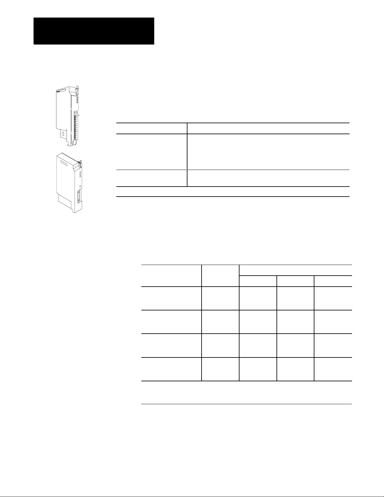
Selecting I/O Adapter
Modules
ASB
ALX
Select I/O adapter modules to interface your PLC-5 processor with I/O
modules. Use Table 2.D as a guide when you select I/O adapter modules.
Table 2.D
Guidelines
Choose: When your requirements are:
1771AS or 1771ASB
Remote I/O Adapter Module
(or 1771AM1, AM2 chassis
with integral power supply and
adapter module)
1771ALX ExtendedLocal I/O
Adapter Module
1
1771ASB
series C and later have 230.4 kbps communication rate in addition to 57.6 kbps and 1
for Selecting Adapter Modules
1
a remote I/O link with:
• 57.6 kbps with a distance of up to 10,000 cable feet or
• timing that isn't critical enough to place I/O modules in a processor local
I/O chassis or an extendedlocal I/O chassis
an extendedlocal I/O link with timing that is critical and all extendedlocal
I/O chassis are located within 100 ft of the processor.
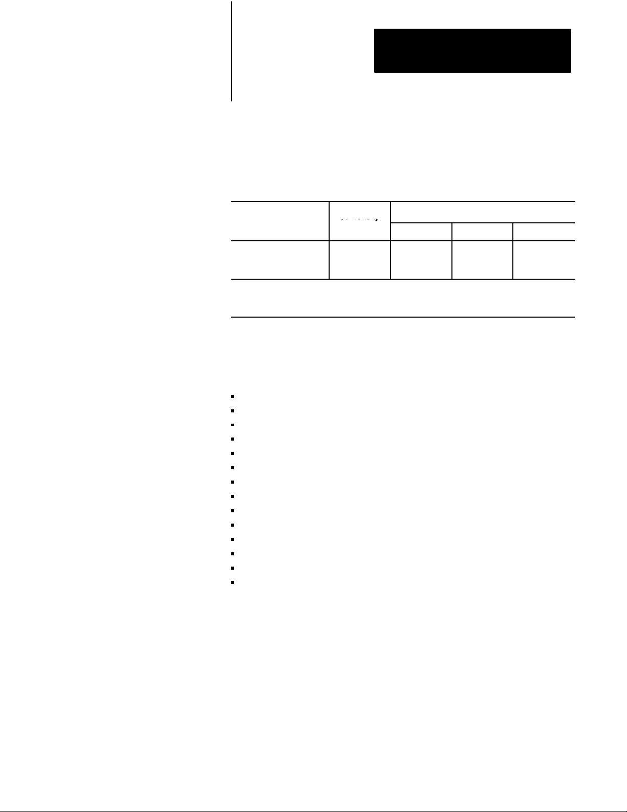
17 71AS/ASB Remote I/O Adapter Modules
Table 2.E shows the I/O density per module and addressing modes you can
use with I/O chassis and remote I/O adapter modules.
Table 2.E
Chassis/Adapter Module Combinations
I/O
15.2 kbps.
Remote I/O Adapter I/O Density
Module Cat. No.
1771AS 8
1771ASB
Series A
1771ASB
Series B, C, and D
1771AM2 8
1
Conditional
adjacent slots (even/odd pair) of the I/O chassis beginning with slot 0. If you cannot pair the
modules this way
module placement; you must use an input module and an output module in two
, leave the adjacent slot empty
per Module
16
32
8
16
32
8
16
32
16
32
.
2Slot 1Slot 1/2Slot
Yes
1
No
Yes
1
No
Yes
1
No
Addressing
No
No
No
Yes
Yes
1
Yes
Yes
1
Yes
Yes
1
No
No
No
No
No
No
Yes
Yes
Yes
Yes
Yes
Yes
Using the 1771-ASB Series C or D adapter module, you can choose one of
three communication rates: 57.6 kbps, 115.2 kbps, or 230.4 kbps.
2-4
Page 24
Chapter 2
Module C
I/O Density
Choosing Hardware
1771ALX ExtendedLocal I/O Adapter Module
Table 2.F shows the I/O density per module and addressing modes you can
use with I/O chassis and extended-local I/O adapter modules.
Table 2.F
Chassis/Extended Local I/O Adapter Module Combinations
I/O
at. No.
1771ALX
Series A
1
Conditional
module placement; you must use an input module and an output module in two adjacent slots (even/
odd pair) of the I/O chassis beginning with slot 0. If you cannot pair the modules this way
empty.
I/O Density
per Module
8
16
32
2Slot 1Slot 1/2Slot
Yes
1
No
Addressing
Yes
Yes
1
, leave the adjacent slot
Other Devices on an I/O Link
Other devices that you can use on a remote I/O link are:
PLC-5 processor in adapter mode
PLC-5/250 remote scanner in adapter mode
PLC interface module for digital ac and dc drives
remote I/O adapter for Bulletin 1336 drives
RediPANELt pushbutton and keypad modules
Datalinert
PanelView (see operator interface)
F30D option module (for T30 plant-floor terminal)
8600 or 9/SERIES CNC with remote I/O adapter option
CVIMt in adapter mode
Pro-Spect 6000 Fastening System with remote I/O adapter option
1747-DCM module (to SLC-500 rack)
1771-DCM module
1771-GMF robot (remote I/O interface module)
Yes
Yes
Yes
See the appropriate Allen-Bradley product catalog for more information on
these devices.
2-5
Page 25
Chapter 2
Choosing Hardware
Selecting
I/O Chassis
4-Slot
1771A1B
An I/O chassis is a single, compact enclosure for the processor,
power-supply modules, remote and extended-local I/O adapter modules,
and I/O modules. The left-most slot of the I/O chassis is reserved for the
processor or adapter module. Consider the following when selecting
a chassis:
When you determine the maximum number of I/O in your application,
allow space for the I/O slots dedicated to power-supply modules,
communication modules, and other intelligent I/O modules.
You must use series B or later chassis with 16- and 32-point
I/O modules.
Allow space for future addition of I/O modules to chassis.
I/O chassis available are:
4-slot (1771-A1B)
8-slot (1771-A2B)
12-slot—rack mount (1771-A3B), panel mount (1771-A3B1)
16-slot (1771-A4B)
You can also choose a chassis with an integral power supply and remote
I/O adapter (show at left). The two types are:
1771AM1
1771AM2
Selecting an Operator
Interface
1-slot (1771-AM1)
2-slot (1771-AM2)
PanelView and ControlView are operator interface products or packages
that communicate with a PLC-5 processor. Use Table 2.G as a guideline
when selecting either PanelView or ControlView for your PLC-5
programmable controller system. Use Table 2.H for a comparison of
PanelView and ControlView features.
2-6
Page 26

Table 2.G
Guidelines
Chapter 2
Choosing Hardware
for Selecting an Operator Interface
Choose this
operator interface:
PanelView
1
For these types of
operations (examples):
Starts/stops, auto/manual operations,
setpoints, outputs, alarms
Explanation:
Used as an operator window to enter commands that make process adjustments such
as starts/stops and loop changes. Can also be used for alarming operations. Can
communicate with a single PLC5 processor on a remote I/O link. Has a fixed number
of devices and amount of data that it can handle. Has builtin error checking. Is an
industrialhardened CRT with pushbuttons, solid state memory and processor, and no
moving parts (i.e., disk drive).
Utilizes pass through, which is the ability to download/upload via DH+/remote I/O links.
ControlView
1
Refer
1
Store, display, and manipulate data
on process performance (i.e., trends,
process graphics, formulas, reports,
and journals)
to your local AllenBradley sales of
Used as an operator window that communicates with a PLC5 processor on Data
Highway Plus (DH+) link. Designed for use as an information link. Can communicate
to multiple PLC processors. ControlView is a software package that runs on an IBMr
DOSbased personal computer.
fice or AllenBradley distributor for more information on PanelV
iew and ControlV
iew.
Table 2.H
Comparison
of PanelV
Category PanelView ControlView
Communication with
PLC processor
Remote I/O
5 block transfers per terminal maximum (32 words per transfer)
1 discrete transfer per terminal (64 words maximum, one way)
This is 8 racks of transfer
Graphics Character graphics
Create screens with PanelBuilder software
Monochrome or color (8 of 16 colors displayed at a time)
Number of
Screens per
Terminal/Workstation
8 to 12 screens of medium complexity typical
200 objects maximum per screen
Limited by terminal memory size: 128 Kbytes
Data Capacity 200 objects maximum per screen 10,000 points maximum in database
Communication
Limited by blocktransfer and discretetransfer timing
Rate
Depends on PLC processor and remote I/O link size
Hardware Keypad or Touchscreen terminals, color or monochrome
AllenBradley, IBM, or compatible computer required for
PanelBuilder software
Programming PanelBuilder software
Menudriven with fillintheblank information entry
Use PanelBuilder to create application file that defines
screens, messages, alarms, then download application file to
PanelView terminal
Messages 496 maximum per terminal Not Applicable
Alarms 496 maximum per terminal 2000 points with Alarming option
Security 8 levels 16 levels with individual operator login capability
Options Remote serial port
EEPROM or EPROM memory
iew and ControlV
DH+ link
Data Highway
Data Highway II Native Mode
Pixel Graphics
Create screens with Mouse Grafix editor option or C Toolkit
EGA, VGA, or equivalent with 256K RAM
Monochrome or color monitor
Limited only by hard disk capacity
50 data entry locations per screen
50 tags per command list per screen
300 tags/points maximum per screen
8 scan classes, each with userconfigurable foreground and
background update times; limited by performance of Data
Highway, DH+, or Data Highway II link
AB, IBM, or compatible computer with 286 or 386
processor, math coprocessor, hard disk required at each
operator station
Create data base online via the menu. Menudriven,
fillintheblank information entry, or import data via the ASCII
import capability
Create screens with the mouse GRAFIX editor option or C
toolkit option
Individual objects with security
Screen lockout
Lots of software options
iew Features
2-7
Page 27

Chapter 2
Choosing Hardware
For more information on selecting and configuring PanelView, see:
PanelView Operator Terminal and PanelBuilder Development Software
User Manual, cat. no. 2711-ND002 version C, PN40061-139-01—
request latest revision
Replacing Node Adapter Firmware for PanelView Terminals Installation
Data, PN40062-236-01—request latest revision
For more information on selecting and configuring ControlView, see:
ControlView Core User Manual, publication 6190-6.5.1
ControlView Allen-Bradley Drivers User Manual,
publication 6190-6.5.5
ControlView Networking User Manual, publication 6190-6.5.9
Other Operator Interfaces
You can use the following as operator interfaces in your PLC-5
processor system:
RediPANEL pushbutton and keypad modules
Dataliner
1784-T47 and 1784-T53 programming terminals
See the appropriate Allen-Bradley product catalog for more information on
these operator interfaces.
2-8
Page 28
Chapter 2
Choosing Hardware
Choosing
a Classic PLC5
Processor for Your
Application
Processor/
No.
Cat.
PLC5/10
(1785LT4)
PLC5/12
(1785LT3)
PLC5/15
(1785LT)
PLC5/25
(1785LT2)
Processor/
Cat. No.
PLC5/10
(1785LT4)
PLC5/12
(1785LT3)
PLC5/15
(1785LT)
PLC5/25
(1785LT2)
Maximum User
Memory Words
6 K
6 K
6 K expandable
to 10 K or 14 K
13 K
expandable to
17 K or 21 K
Number of Remote I/O, ExtendedLocal
I/O, and DH+ Ports
•
1 DH+
•
1 DH+
•
1 Remote I/O (Adapter Only)
•1
DH+
•
1 Remote I/O (Adapter or Scanner)
•1
DH+
•
1 Remote I/O (Adapter or Scanner)
EEPROM Module
Memory (W
Module Number
8 K (1785MJ)
8 K (1785MJ)
8 K (1785MJ)
8 K (1785MJ) or
16 K (1785MK)
ords) &
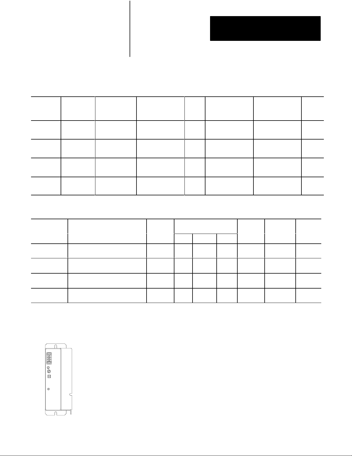
Choose from the following PLC-5 processors.
Table 2.I
PLC5 Processor Selection ChartPart 1
Classic
Total I/O Maximum
(any mix)
•
512 (32I/O modules)
•
256 (16I/O modules)
•
128 (8I/O modules)
•
512 (32I/O modules)
•
256 (16I/O modules)
•
128 (8I/O modules)
•
512 (any mix) or
•
512 in + 512 out
(complementary)
•
1024 (any mix) or
•
1024 in + 1024 out
(complementary)
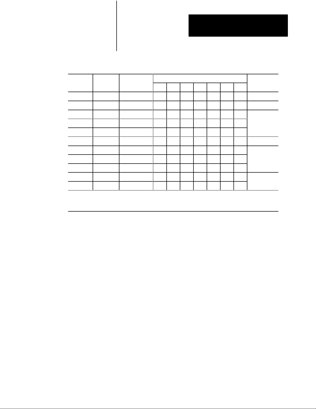
Table 2.J
PLC5 Processor Selection ChartPart 2
Classic
Maximum
Number of
I/O Racks
1 1 0 0 0 2.5A
4 1 0 0 0
4 13 0 12 0
8 17 0 16 0
Analog
I/O Max
256
256
512
1024
Maximum Number of I/O
Chassis
Total
Program Scan T
K W
2 ms (discrete logic)
8 ms (typical)
2 ms (discrete logic)
8 ms (typical)
2 ms (discrete logic)
8 ms (typical)
2 ms (discrete logic)
8 ms (typical)
Ext Local
ord
Remote
ime /
Number of
RS232/
422/ 423
ports
I/O Scan time/Rack
(in a single Chassis,
extlocal or remote)
N/A
•
10 ms @ 57.6 kbps
(remote)
•
10 ms @ 57.6 kbps
(remote)
•
10 ms @ 57.6 kbps
(remote)
Remote I/O
Transmission
1
Rates
57.6 kbps
57.6 kbps
57.6 kbps
Multiple
MCPs /
Quantity
No / 1
No / 1
No / 1
No / 1
Backplane
Current
Load
2.5A
2.5A
2.5A
Selecting Power Supplies
1771P7
Use the following steps as guidelines for selecting a power supply for a
chassis that contains a PLC-5 processor, a 1771-AS or -ASB remote I/O
adapter module, or a 1771-ALX extended-local I/O adapter module.
1. Determine the input voltage for the power supply.
2. Calculate the total backplane current draw for I/O modules by
adding together the backplane current draw for each I/O module in
that chassis.
2-9
Page 29

Chapter 2
Choosing Hardware
3. Add to the total of the I/O module backplane current draw either:
a. 3.3 Amps when the chassis will contain a PLC-5 processor
(maximum current draw for any PLC-5 processor) or
b. 1.2 Amps when the chassis will contain either a remote I/O
1771-AS or -ASB module or a 1771-ALX extended-local I/O
adapter module
4. If you leave slots available in your chassis for future expansion:
a. list backplane current draw for future I/O modules
b. add the total current draw for all expansion I/O modules to the
total calculated in step 3.
5. Determine whether the available space for the power supply is in the
chassis or mounted external to the chassis.
Choose your power supply from Table 2.K or Table 2.L using the input
voltage requirement and the total backplane current draw as determined in
the previous steps, 1 through 5.
See the Automation Products Catalog, publication AP100, for more
information on power supplies.
Powering a Chassis Containing a PLC5 Processor
Table 2.K lists the power-supply modules that you can use with a Classic
PLC-5 processor.
2-10
Page 30
Chapter 2
Power
Input
Output Current
Power Supply
Choosing Hardware
Table 2.K
Powering
Power
Input Output Current
Supply
1771P3 120V ac 3 6 11 11 chassis, 1slot
1771P4 120V ac 8 11 16 16 chassis, 2slot
1771P4S 120V ac 8 11 16 16
1771P4S1 100V ac 8 16
1771P4R 120V ac 8/16/24
1771P5 24V dc 8 16 chassis, 2slot
1771P6S 220V ac 8 16
1771P6S1 200V ac 8 16
1771P6R 220V ac 8/16/24
1771P7 120/220V ac 16
1771PS7 120/220V ac 16
1
See
publication 17712.136 for more information.
2
Y
ou cannot use an external power supply and a slotbased power supply module to power the same chassis;
they are not compatible.
Power
a Chassis Containing a Classic PLC5 processor
Output Current (in Amps) When Parallel with:
(in Amps)
P3 P4 P4S P4S1 P5 P6S P6S1
1
1
Power Supply
Location
chassis, 1slot
chassis, 1slot
2
external
2-11
Page 31

Chapter 2
Power
Input
Output Current
Power Supply
Choosing Hardware
Powering a Remote I/O Chassis Containing a 1771AS or 1771ASB or
an ExtendedLocal I/O Chassis Containing a 1771ALX
Table 2.L lists the power supply modules that you can use with a remote
I/O chassis or an extended-local I/O chassis.
Table 2.L
Powering
a Remote I/O Chassis (Containing a 1771AS or ASB)
or an ExtendedLocal I/O Chassis (Containing a 1771ALX)
Power
Input Output Current
Supply
Power
(in Amps)
1771P3 120V ac 3 6 11 11 chassis, 1slot
1771P4 120V ac 8 11 16 16 chassis, 2slot
1771P4S 120V ac 8 11 16 16
1771P4S1 100V ac 8 16
1771P4R 120V ac 8/16/24
1771P5 24V dc 8 16 chassis, 2slot
1771P6S 220V ac 8 16
1771P6S1 200V ac 8 16
1771P6R 220V ac 8/16/24
1771P1 120/220V ac 6.5
1771P2 120/220V ac 6.5
1771P7 120/220V ac 16
1771PS7 120/220V ac 16
Output Current (in Amps) When Parallel with:
P3 P4 P4S P4S1 P5 P6S P6S1
1
1
Power Supply
Location
chassis, 1slot
chassis, 1slot
2
external
2-12
1777P2 120/220V ac 9
1777P4 24V dc 9
1
See
publication 17712.136 for more information.
2
Y
ou cannot use an external power supply and a slotbased power supply module to power the same chassis;
they are not compatible.
Page 32

Chapter 2
Choosing Hardware
Selecting
Memory Modules
Selecting a Replacement
Battery
Select a memory module from Table 2.M for your PLC-5 processor.
Table 2.M
Processor Memory Modules
PLC5
Nonvolatile Memory Backup (EEPROM) RAM Memory (CMOS)
Words Catalog Number (and Processor) Words Catalog Number (and Processor)
8 K 1785MJ 4 K 1785MR (PLC5/15 and 5/25)
16 K 1785MK (PLC5/25) 8 K 1785MS (PLC5/15 and 5/25)
A battery ships with your PLC-5 processor. Select a replacement battery
using Table 2.N and Table 2.O. See the Allen-Bradley Guidelines for
Handling Lithium Batteries, publication ICCG-5.14, for more information.
Table 2.N
Processor
Processor Battery
PLC5/10, 5/12, 5/15,
and 5/25
1
The
their part number TL 5104 and type AEL/S.
Batteries
1770XY is a 3.6 V
1
1770XY, AA
lithium
olt AA size lithium thionyl chloride battery manufactured by T
Function
Retains the processor memory and the
memory in an optional CMOS RAM module
if the processor is not powered.
adiran as
Selecting
Complementary I/O
Table 2.O
Average
Battery Life
Battery Temperature Power Off 100%
1770XY
60° C
25° C
(Average)
329 days
2 years
Power Off 50%
(Average)
1.4 years
3.3 years
You configure complementary I/O by assigning an I/O rack number of one
I/O chassis (primary) to another I/O chassis (complementary). You
complement I/O functions in the primary chassis with opposite functions in
the complementary chassis. Use chapter 4, “Assigning Addressing Mode,
Racks, and Groups,” in conjunction with the following selection of
complementary I/O hardware.
2-13
Page 33

Chapter 2
Choosing Hardware
Use the following modules in either primary or complementary I/O chassis
opposite any type of module:
Communication Adapter Module (1771-KA2)
Communication Controller Module (1771-KE)
PLC-2 Family/RS-232-C Interface Module (1771-KG)
Fiber Optics Converter Module (1771-AF)
DH/DH+ Communication Adapter Module (1785-KA)
DH+/RS-232C Communications Interface Module (1785-KE)
Use the following modules in either primary or complementary I/O chassis
opposite any type of module. However, these modules do not work as
standalone modules; each one has an associated master module. Use care
when placing the master modules in the I/O chassis (refer to the paragraph
on Master/Expander I/O modules):
Analog Input Expander Module (1771-E1, -E2, -E3)
Analog Output Expander Module (1771-E4)
Servo (Encoder Feedback) Expander Module (1771-ES)
Pulse Output Expander Module (1771-OJ)
Selecting
a PLC5 Processor
Backup System
A PLC-5 processor backup system contains two of each of the following
hardware components:
Classic PLC-5 processor module
Processor Catalog Number
PLC5/15 1785LT Series B
PLC5/25 1785LT2
1785-BCM Series C Backup Control Module (for 2 channels)
1785-BEM Backup Expansion Module (for 2 additional channels)
Power supply
Local chassis
Important: The PLC-5 backup system does not back up I/O in the
processor-resident local chassis. Do not install I/O in the processorresident local chassis of a backed up system.
Refer to the PLC-5 Backup Communication Module User Manual,
publication 1785-6.5.4, for more information on configuring a PLC-5
processor backup system.
2-14
Page 34

Chapter 2
Choosing Hardware
Selecting Link Terminators
Connecting a
Programming Terminal to a
Processor Module
Terminate remote I/O links by setting switch assembly SW3. If you cannot
use an 82-Ohm terminator because of devices that you place on your I/O
link (see the table below for a list of these devices), you must use 150-Ohm
terminators. Using the higher resistance reduces the quantity of devices to
16 that you can place per remote I/O link. Also, this limits your
communication rates to 57.6 kbps and 115.2 kbps.
DH+ Network Terminator
Terminate your DH+ network with a 150-Ohm, 1/2-watt terminator.
If you have this processor: Terminate a DH+ link by:
PLC5/10, 5/12, 5/15, or 5/25 Setting switch assembly SW3 of the PLC5
processor (refer to your Classic 1785 PLC5 Family
Programmable Controllers Hardware Installation
Manual, publication 17856.6.1).
Connect the programming terminal directly to the processor through the
D-shell DH+ COMM INTFC connector on the front panel. You can also
connect the programming terminal remotely to a DH+ link through the
3-pin connector or at a remote station.
Choosing Cables
Select cables from the options listed below. See chapter 3, “Placing System
Hardware,” to determine the lengths that you will need for cables in
your system.
Remote I/O Link
Use Belden 9463 twinaxial cable (1770-CD) to connect your PLC-5
processor to remote I/O adapter modules.
Connect your I/O devices using:
single-conductor wire (analog and some discrete applications)
multi-conductor cable (analog and some discrete applications)
multi-conductor shielded cable (some specialty I/O modules and
low-voltage dc discrete modules)
2-15
Page 35

Chapter 2
PLC 5/10, 5/12, 5/15
1784 KT, KT2
1784 CP
Choosing Hardware
See the Classic 1785 PLC-5 Programmable Controllers Hardware
Installation Manual, publication 1785-6.6.1, and the installation data for
the I/O modules that you have selected for more information on I/O wiring.
Also, see Allen-Bradley Programmable Controller Wiring and Grounding
Guidelines, publication 1770-4.1, and Control, Communication and
Information Reference Guide, publication ICCG-1.2, for more information.
Programming Terminal
The cable that you use to connect a processor to a programming terminal
depends on the communication device used. Table 2.P lists the cables that
you need for different configurations.
Table 2.P
Cables
for Connecting a Classic PLC5 Processor and Programming
Terminal
If you have this device: With this
PLC5/10, 5/12, 5/15, 1784KT, KT2 1784CP
or 5/25
6160T60, 6160T70, 6121
IBM PC/AT (or compatible)
1784T47, 6123, 6124
IBM PC/XT (or compatible)
6120, 6122 1785KE 1784CYK
communication device:
,
1784KL, KL/B
1784KTK1 1784CP5
1784PCMK 1784PCM5
1785KE 1784CAK
1785KE 1784CXK
Use this cable:
You can also use a 1770-KF2/B communication interface to connect to a
PLC-5 processor. You build your own cables to connect your
programming terminal via the COM1 or COM2 serial ports to the
1770-KF2/B. For the cable pin assignments, see the Classic 1785 PLC-5
Programmable Controller Hardware Installation Manual, publication
1785-6.6.1.
2-16
Page 36

Chapter
Placing System Hardware
3
Chapter
Objectives
Determining the Proper
Environment
A well-planned layout is essential to the proper installation of your Classic
PLC-5 programmable controller system. Read this chapter for information
on placing hardware.
System Design
If you want to read about: Go to
page:
Proper environment 31
Protecting your system 34
Avoiding electrostatic damage 34
Planning your raceway layout 34
Planning your cabling 36
Grounding your system 37
Determined
Choosing Hardware
Placing System
Hardware
Assigning Addressing
Mode, Racks,
and Groups
Choosing
Communication
Planning Your
System Programs
Selecting Interrupt
Routines
Transferring Discrete
and Block Data
Calculating Program
Timing
Place the processor in an environment with conditions that fall within the
guidelines described in Table 3.A.
Table 3.A
Proper
Environmental Conditions For Y
Environmental Condition Acceptable Range
Operating temperature
Storage temperature
Relative humidity 5 to 95% (without condensation)
0 to 60° C (32 to 140° F)
40 to 85° C (40 to 185° F)
our Processor
Separate your programmable controller system from other equipment and
plant walls to allow for convection cooling. Convection cooling draws a
vertical column of air upward over the processor. This cooling air must
not exceed 60
If the air temperature exceeds 60
° C (140° F) at any point immediately below the processor.
° C, install fans that bring in filtered air or
recirculate internal air inside the enclosure, or install air-conditioning/heatexchanger units.
3-1
Page 37

Chapter 3
Placing System Hardware
To allow for proper convection cooling in enclosures containing a
processor-resident chassis and remote I/O chassis, follow these guidelines.
Minimum spacing requirements for a
processorresident chassis:
102mm
(4")
51mm(2")
Area reserved for disconnect.
transformer, control relays, motor
starters or other user devices.
(6")
51mm
(2")
Wiring Duct
153mm
153mm
(6")
• Mount the I/O chassis horizontally.
• Allow 153 mm (6 in) above and below the chassis.
• Allow 102 mm (4 in) on the sides of each chassis.
• Allow 51 mm (2 in) vertically and horizontally between
any chassis and the wiring duct or terminal strips.
• Leave any excess space at the top of the enclosure,
where the temperature is the highest.
102mm
(4")
13081
3-2
Page 38

153mm (6")
102mm
(4")
51mm (2")
51mm (2")
Area reserved for disconnect.
transformer, control relays,mot or
starters or other user devices.
153mm
(6")
Wiring Duct
Chapter 3
Placing System Hardware
Minimum spacing requirements for a remote
I/O chassis:
• Mount the I/O chassis horizontally.
• Allow 153 mm (6 in) above and below all
chassis. When you use more than one
chassis in the same area, allow 152.4 mm
(6 in) between each chassis.
• Allow 102 mm (4 in) on the sides of each
chassis. When you use more than one
chassis in the same area, allow 101.6 mm
(4 in) between each chassis.
• Allow 51 mm (2 in) vertically and
horizontally between any chassis and the
wiring duct or terminal strips.
• Leave any excess space at the top of
the enclosure, where the temperature is
the highest.
102mm
(4")
102mm
(4")
153mm (6")
Wiring Duct
18749
3-3
Page 39

Chapter 3
Placing System Hardware
Protecting Your Processor
Avoiding Electrostatic
Damage
You provide the enclosure for your processor system. This enclosure
protects your processor system from atmospheric contaminants such as oil,
moisture, dust, corrosive vapors, or other harmful airborne substances. To
help guard against EMI/RFI, we recommend a steel enclosure.
Mount the enclosure in a position where you can fully open the doors. You
need easy access to processor wiring and related components so that
troubleshooting is convenient.
When you choose the enclosure size, allow extra space for transformers,
fusing, disconnect switch, master control relay, and terminal strips.
ATTENTION: Under some conditions, electrostatic
discharge can degrade performance or damage the processor
module. Read and observe the following precautions to guard
against electrostatic damage.
Wear an approved wrist strap grounding device when
handling the processor module.
Laying Out Your
Cable Raceway
Touch a grounded object to discharge yourself before
handling the processor module.
Do not touch the backplane connector or connector pins.
When not handling the processor module, keep it in its
protective packaging.
The raceway layout of a system reflects where the different types of I/O
modules are placed in I/O chassis. Therefore, you should determine
I/O-module placement prior to any layout and routing of wires. When
planning your I/O-module placement, however, segregate the modules
based on the conductor categories published for each I/O module so that
you can follow these guidelines. These guidelines coincide with the
guidelines for “the installation of electrical equipment to minimize
electrical noise inputs to controllers from external sources” in IEEE
standard 518-1982.
3-4
Page 40

Chapter 3
Placing System Hardware
To plan a raceway layout, do the following:
categorize conductor cables
route conductor cables
Categorize Conductors
Segregate all wires and cables into categories as described in the Industrial
Automation Wiring and Grounding Guidelines, publication 1770-4.1. See
the installation data for each I/O module that you are using for information
about its classification.
Route Conductors
To guard against coupling noise from one conductor to another, follow the
general guidelines for routing cables described in the Industrial
Automation Wiring and Grounding Guidelines, publication 1770-4.1. You
should follow the safe grounding and wiring practices called out in the
National Electrical Code (NEC, published by the National Fire Protection
Association, in Quincy, Massachusetts), and local electrical codes.
Planning Cabling
DH+ Link Cabling
At a DH+ transmission rate of 57.6 kbps, do not exceed 3,048 cable-m
(10,000 cable-ft) for a trunkline cable length or 30.5 cable-m (100 cable-ft)
for a dropline cable length.
Remote I/O Link Cabling
Refer to Table 3.B for remote I/O link trunkline cable length restrictions.
Table 3.B
Maximum
Transmission Rate Maximum Cable Length
57.6 kbps 3,048 m (10,000 ft)
115.2 kbps 1,524 m (5000 ft)
230.4 kbps 762 m (2500 ft)
Important: All devices on the remote I/O link must be communicating at
the same transmission rate.
Cable Lengths per Communication Rate
3-5
Page 41

Chapter 3
Placing System Hardware
Laying Out the
Backpanel Spacing
1771A1B
1771A2B
1771A3B1
1771A4B
Power
Connector
193mm
(7.60")
Side
Use 6.35 mm (0.25 inch) mounting bolts to attach the I/O chassis to the
enclosure backpanel.
Figure 3.1
Chassis
1
Dimensions (Series B)
315mm
(12.41")
591mm
(23.25")
337mm
(13.25")
464mm
(18.25")
210mm
(8.25")
16slot 1771
12slot
8slot
4slot
254mm
(10")
1771A3B
217mm
(8.54")
Side
1
171mm
(6.75")
339mm
(13.53")
610mm
483mm
(19.01")
229mm
(9.01")
465mm
(18.31")
(24.01")
356mm
(14.01")
484mm
(19")
Front
1
Total
maximum depth dimension per installation will be dependent upon module wiring and connectors.
16slot 1771A4B
12slot 1771A3B1
8slot 1771A2B
4slot 1771A1B
9mm
(.34")
26mm
(1.02")
178mm
(7")
130mm
(5.10")
12450I
3-6
Page 42

Chapter 3
Placing System Hardware
Figure 3.2
Chassis and 1771P2 Power Supply Dimensions
I/O
591mm
Use .25" dia
mounting bolts
(4 places)
(23.25")
337mm
(13.25")
464mm
(18.25")
210mm
(8.25")
16-slot
12-slot
8-slot
4-slot
Grounding Configuration
315mm
(12.41")
Clearance depth is 204 mm (8 in) for 8 I/O connection points per module.
1771P1
1771P2
1771P7
1771PS7
Power Supply
91mm
(3.6")
483mm
(19.01")
229mm
(9.01")
610mm
(24.01")
356mm
(14.01")
See Figure 3.3 for the recommended grounding configuration for remote
I/O systems.
Figure 3.3
Recommended
Grounding Configuration for Remote I/O Systems
254mm
(10")
16-slot 1771-A4B
12-slot 1771-A3B1
8-slot 1771-A2B
4-slot 1771-A1B
12451I
Enclosure
Ground
Bus
Grounding Electrode Conductor
To Grounding
Electrode
System
I/O Chassis Wall
Star
Washer
Ground Lug
Ground
Lug
Nut
15561
3-7
Page 43

Chapter
4
Assigning Addressing Modes,
Racks, and Groups
Chapter
Objectives
This chapter conveys basic hardware addressing concepts and gives you
guidelines with which to choose the addressing modes (including
complementary I/O), racks, and groups to use in your system.
System Design
If you want to read about: Go to
page:
Placing I/O modules in chassis 41
Understanding terms 42
Choosing I/O addressing mode 43
Rack number assignments 49
Addressing complementary I/O 412
Determined
Choosing Hardware
Placing System
Hardware
Assigning Addressing
Mode, Racks,
and Groups
Choosing
Communication
Planning Your
System Programs
Selecting Interrupt
Routines
Transferring Discrete
and Block Data
Calculating Program
Timing
Placing I/O Modules
in Chassis
Place I/O modules in a chassis depending on the electrical characteristics
of the modules. The placement is made left to right, with the left-most
position being closest in the chassis to the PLC-5 processor or the I/O
adapter module. The placement order is as follows:
1. block-transfer modules (all types)
2. dc input modules, placed left to right from lowest to highest voltages
3. dc output modules, placed left to right from lowest to highest voltages
4. ac input modules, placed left to right from lowest to highest voltages
5. ac output modules, placed left to right from lowest to highest voltages
4-1
Page 44

Chapter 4
Assigning Addressing Modes,
Racks, and Groups
The following guidelines are for placing block-transfer modules.
Place as many modules as possible for which you need fast
block-transfer times in your processor-resident local I/O chassis .
Place modules that need fast block-transfer times (but space is not
available in processor-resident local I/O chassis) in an extended-local
I/O chassis.
Place modules in which timing is not as critical as in other
block-transfer modules in remote I/O chassis.
ac output modules should always be the furthest I/O modules from any
block-transfer modules in the same chassis.
Understanding the Terms
Used in this Chapter
Become familiar with the following terms and their definitions:
An I/O group is an addressing unit that corresponds to an input
image-table word (16 bits) and an output image-table word (16 bits). An
I/O group can contain up to 16 inputs and 16 outputs; and it can occupy 2-,
1-, or 1/2-module slots for addressing purposes.
Output or
Input
Terminals
00
01
02
03
04
05
06
07
10
11
12
13
14
15
16
17
Output
Terminals
00
01
02
03
04
05
06
07
10
11
12
13
14
15
16
17
Input
Terminals
00
01
02
03
04
05
06
07
10
11
12
13
14
15
16
17
4-2
2Slot I/O Module Group 1Slot I/O Module Group
(I/O Group #0) (I/O Group #0)
13073
Page 45

Chapter 4
Assigning Addressing Modes,
Racks, and Groups
An I/O rack is an addressing unit that corresponds to 8 input image-table
words and 8 output image-table words. A rack contains 8 I/O groups.
Choosing the
Addressing Mode
I/O Group Numbers
1234
0
.
567
13074
Depending on I/O chassis size and I/O group size, an I/O rack can occupy
a fraction of an I/O chassis, a full I/O chassis, or multiple I/O chassis.
Select an addressing mode for each chassis independently, based on the
type and density of the I/O modules contained therein. When you select
addressing mode, limit the number of remote I/O adapters and I/O modules
to the maximum number that the PLC-5 processor can support.
Using 2Slot Addressing
When you select 2-slot addressing, the processor addresses two I/O
module slots as one I/O group. Each physical 2-slot I/O group corresponds
to one word (16 bits) in the input image table and one word (16 bits) in the
output image table. The type (unidirectional or bidirectional) and density
of a module that you install determines the number of bits that are used in
each word.
Important: You cannot use 32-point I/O modules with 2-slot addressing.
4-3
Page 46

Chapter 4
Assigning Addressing Modes,
Racks, and Groups
8-Point I/O Modules
Eight-point digital discrete I/O modules have a maximum of eight inputs or
up to eight outputs. Because they do not interfere with each other’s I/O
image, you can place any mix of 8-point I/O modules (including
bidirectional modules, such as block-transfer modules) in any order.
2Slot I/O Group with Two 8pt Input Modules
2-Slot
I/O Group
Input
Terminals
00
01
02
03
04
05
06
07
Input
Terminals
10
11
12
13
14
15
16
17
2Slot I/O Group with One 8pt Input Module
and One 8pt Output Module
2-Slot
I/O G roup
Input
Terminals
00
01
02
03
04
05
06
07
Output
Terminals
10
11
12
13
14
15
16
17
Output ImageTable Word Corresponding to the I/O Group.
17 16 15 14 12 10 07 06 05 03 02 01 00041113
Unused
Input ImageTable Word Corresponding to the I/O Group.
17 16 15 14 12 10 07 06 05 03 02 01 00041113
This
I/O group uses 16 bits of the input image table.
4-4
11867
Output ImageTable Word Corresponding to the I/O Group.
17 16 15 14 12 10 07 06 05 03 02 01 00041113
Output Bits Used
Input ImageTable Word Corresponding to the I/O Group.
17 16 15 14 12 10 07 06 05 03 02 01 00041113
This
I/O group uses 8 bits of the input image table and
Unused
Input Bits UsedAlways 0
8 bits of the output image table.
14965
Page 47

Chapter 4
Assigning Addressing Modes,
Racks, and Groups
16-Point I/O Modules
Sixteen-point digital discrete I/O modules have up to 16 inputs or up to
16 outputs. A 16-point I/O module uses a full word in the input or output
image table.
2Slot I/O Group with One 16pt Input Module
and One 16pt Output Module
2-Slot
I/O Group
Input
Terminals
00
01
02
03
04
05
06
07
10
11
12
13
14
15
16
17
Output
Terminals
00
01
02
03
04
05
06
07
10
11
12
13
14
15
16
17
01234567
IOIOIOIOIOIOIOIO
Word #
Word #
Output Image Table
0
1
2
3
4
5
6
7
I/O Group Designation
I/O Chassis Containing
16pt Modules
Input/Output Designation
Input Image Table
0
1
2
3
4
5
6
7
Output ImageTable Word Corresponding to the I/O Group.
17 16 15 14 12 10 07 06 05 03 02 01 00041113
Input ImageTable Word Corresponding to the I/O Group.
17 16 15 14 12 10 07 06 05 03 02 01 00041113
This
I/O group uses 16 bits of the input image table and
16 bits of the output image table.
15559
Because
each 16pt module uses a full word in the
image table, the only type of module that you can install
in a 2slot I/O group with a 16pt input module is an 8 or
16pt output module that performs a complementary
function (inputs and outputs complement each other).
Since all blocktransfer modules are bidirectional,
they cannot be used to complement either input or
output modules.
4-5
Page 48

Chapter 4
Assigning Addressing Modes,
Racks, and Groups
Using 1Slot Addressing
When you select 1-slot addressing, the processor addresses one I/O
module slot as one I/O group. Each physical slot in the chassis
corresponds to an input and output image-table word. The type
(unidirectional or bidirectional) and density of module that you install
determines the number of bits used in these words.
1Slot
I/O Group with One 16pt Digital Discrete
I/O Module
1-Slot
I/O Group
Input
Terminals
0
01
02
03
04
05
06
07
10
11
12
13
14
15
16
17
or
1-Slot
I/O G roup
Output
Terminals
00
01
02
03
04
05
06
07
10
11
12
13
14
15
16
17
8-Point I/O Modules
You can place any mix of 8- or 16-point I/O modules
(including bidirectional modules such as
block-transfer modules) in any order with 1-slot
addressing. The 8- or 16-point modules do not
interfere with the I/O image of the other 8- or
16-point modules.
16-Point I/O Modules
A single 16-point module uses an entire word of the
processor image table.
Block-Transfer Module Addressing
To address a single-slot block transfer module in a
1-slot I/O group, use the assigned I/O rack and group
numbers of the slot (in which the module resides) and
0 for the module number. To address a double-slot
block-transfer module, use the assigned I/O rack
number, the lower assigned I/O group number, and 0
for the module number.
Output ImageTable Word Corresponding to the I/O Group.
17 16 15 14 12 10 07 06 05 03 02 01 00041113
Input ImageTable Word Corresponding to the I/O Group.
17 16 15 14 12 10 07 06 05 03 02 01 00041113
A single 16pt module uses an entire word of image table.
4-6
11869
Page 49
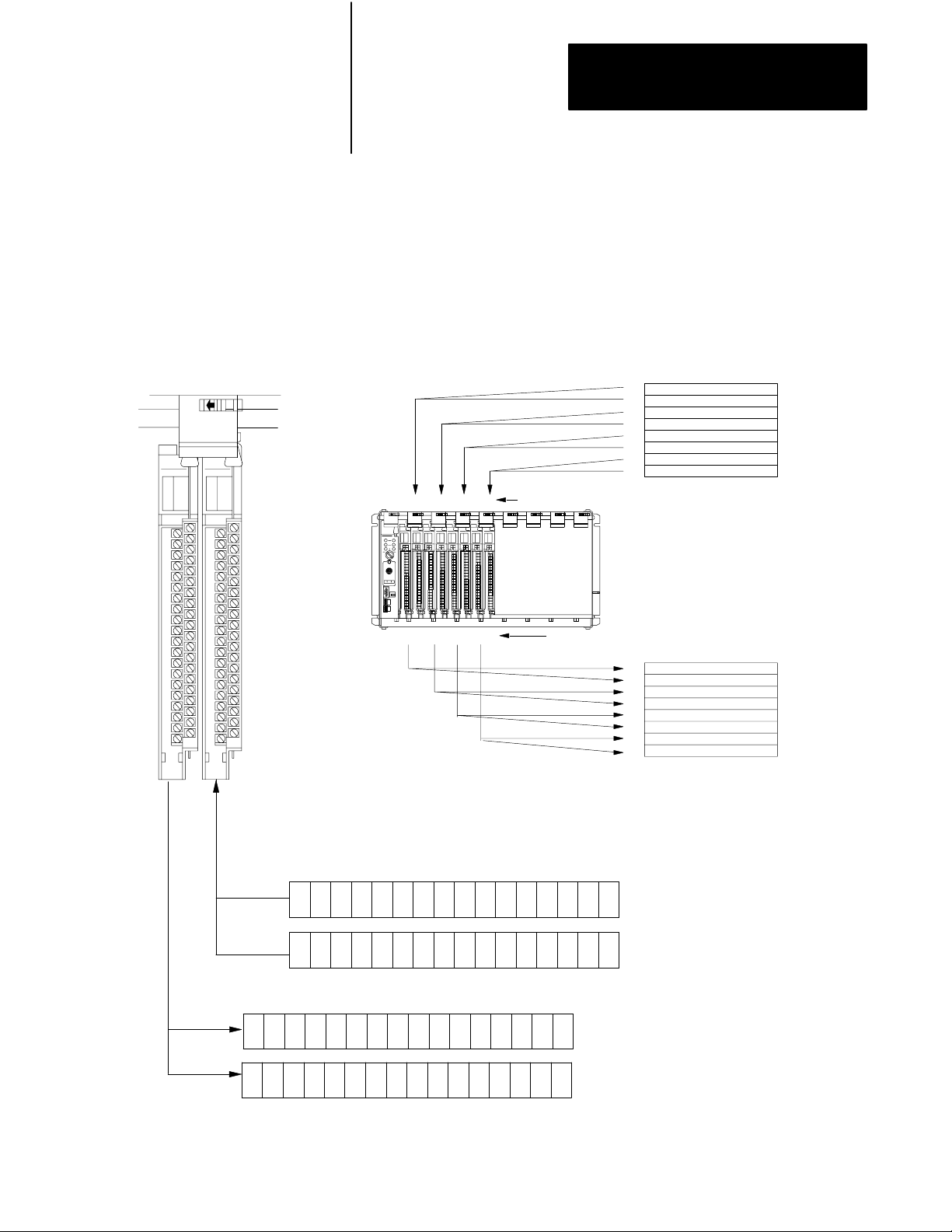
Chapter 4
Assigning Addressing Modes,
Racks, and Groups
32-Point I/O Modules
To use 32-point I/O modules with 1-slot addressing, you must install, as a
pair, an input module and an output module in two adjacent slots (even/odd
pair) of the I/O chassis, beginning with I/O slot 0. If you cannot pair the
modules in this way, one of the two slots of the pair must be empty. For
example, if I/O slot 0 holds a 32-point input module, I/O slot 1 must hold
an 8-, 16-, or 32-point output module (or a module using the backplane for
power only); otherwise the slot must be empty.
1Slot
I/O Group with 32pt I/O Modules
Slot 0
Input Module
I/O Group 0, 1
Slot 1
Output Module
I/O Group 0, 1
2301
IOI IOIOO
4567
Wor d #
I/O Group Designation
I/O Chassis with 1Slot Addressing
Input/Output Designation
Word #
Output Image Table
0
1
2
3
4
5
6
7
Input Image Table
0
1
2
3
4
5
6
7
Output ImageTable Words Corresponding to I/O Groups 0 and 1.
06
07
17 16 15 14 12
17 16 15 14 12
Input
ImageT
able W
ords
17 16 15 14 12
17 16 15 14 12
13
13
07
07
11
11
10
10
06
06
05 03
13
13
Corresponding to I/O Groups 0 and 1.
10
11
10
11
06
07
04
05 03
04
05 03
05 03
02 01
02 01 00
04
04
02 01 00
02 01 00
00
000
001
000
001
14258
4-7
Page 50

Chapter 4
Assigning Addressing Modes,
Racks, and Groups
1/2Slot
I/O Group with One 32pt Input Module
17 010 7
17 10 07
Input Word 0
Output Word 0
Unused
Using 1/2Slot Addressing
When you select 1/2-slot addressing, the processor addresses one-half of
an I/O module slot as one I/O group. Each physical slot in the chassis
corresponds to two input and two output image-table words. The type
(unidirectional or bidirectional) and density of the module that you install
determines the number of bits that are used in each word.
You can mix 8-, 16- and 32-pt I/O modules
in any order in the I/O chassis because 32
input bits and 32 output bits are available in
ImageTable
Words Allocated
for I/O Group 0
the image table for each I/O slot. When you
use 8- and 16-pt I/O modules with 1/2-slot
addressing, however, you use fewer total I/O
bits in our image table.
1/2-Slot
I/O Group
0
1/2-Slot
I/O Group
1
Input
01
03
05
07
11
13
15
17
01
03
05
07
11
13
15
17
Input
#
-
-
-
-
#
00
02
04
06
10
12
14
16
00
02
04
06
10
12
14
16
-
1/2-Slot
I/O Group
0
1/2Slot
I/O Group
1
456
2
0
3
1
IIOO
I/O Group Designation
7
Word #
0
1
2
3
4
5
6
7
I/O Chassis with 1/2Slot Addressing
Input/Output Designation
Word #
0
1
2
3
4
5
6
7
Output Image Table
I
nputImageTable
14974
Not
Used
Always
0
Input Word 1
17 10 07
Output Word 1
17 10 07
Unused
This I/O group uses two words of the image table.
4-8
ImageTable
Words Allocated
for I/O Group 1
Page 51

Chapter 4
Assigning Addressing Modes,
Racks, and Groups
Summary
Table 4.A summarizes the guidelines for selecting an addressing mode.
Addressing
Mode
2slot
1slot
1/2slot
Table 4.A
Addressing
Guidelines
• Two I/O module slots = 1 group
• Each physical 2slot I/O group corresponds to one word (16 bits) in the input image table and one word
(16 bits) in the output image table
• When you use 16point I/O modules, you must install as a pair an input module and an output module in
an I/O group; if you use an input module in slot 0, you must use an output module in slot 1 (or it must be
empty). This configuration gives you the maximum usage of I/O.
• You cannot use a blocktransfer module and a 16point module in the same I/O group because
blocktransfer modules use 8 bits in both the input and output table. Therefore, 8 bits of the 16point
module would conflict with the blocktransfer module.
• You cannot use 32point I/O modules.
• One I/O module slot = 1 group
• Each physical slot in the chassis corresponds to one word (16 bits) in the input image table and one
word (16 bits) in the output image table
• When you use 32point I/O modules, you must install as a pair an input module and an output module in
an even/odd pair of adjacent I/O group; if you use an input module in slot 0, you must use an output
module in slot 1 (or it must be empty). This configuration gives you the maximum usage of I/O.
• Use any mix of 8 and 16point I/O modules, blocktransfer or intelligent modules in a single I/O chassis.
Using 8point modules results in fewer total I/O.
• One half of an I/O module slot = 1 group
• Each physical slot in the chassis corresponds to two words (32 bits) in the input image table and two
words (32 bits) in the output image table
• Use any mix of 8, 16, and 32point I/O or blocktransfer and intelligent modules. Using 8point and
16point I/O modules results in fewer total I/O.
• With the processorresident local rack set for 1/2slot addressing, you cannot force the input bits for the
upper word of any slot that is empty or that has an 8point or 16point I/O module. For example, if you
have an 8point or a 16point I/O module in the first slot of your local rack (words 0 and 1 of the I/O
image table, 1/2slot addressing), you cannot force the input bits for word 1 (I:001) on or off.
Mode Summary
Assigning
Racks
The number of racks in a chassis depends on the chassis size and the
addressing mode:
If using this
chassis size:
4slot 1/4 rack 1/2 rack 1 rack
8slot 1/2 rack 1 rack 2 racks
12slot 3/4 rack 11/2 racks 3 racks
16slot 1 rack 2 racks 4 racks
With 2slot
addressing,
rack type is:
With 1slot
addressing,
rack type is:
With 1/2slot
addressing,
rack type is:
4-9
Page 52
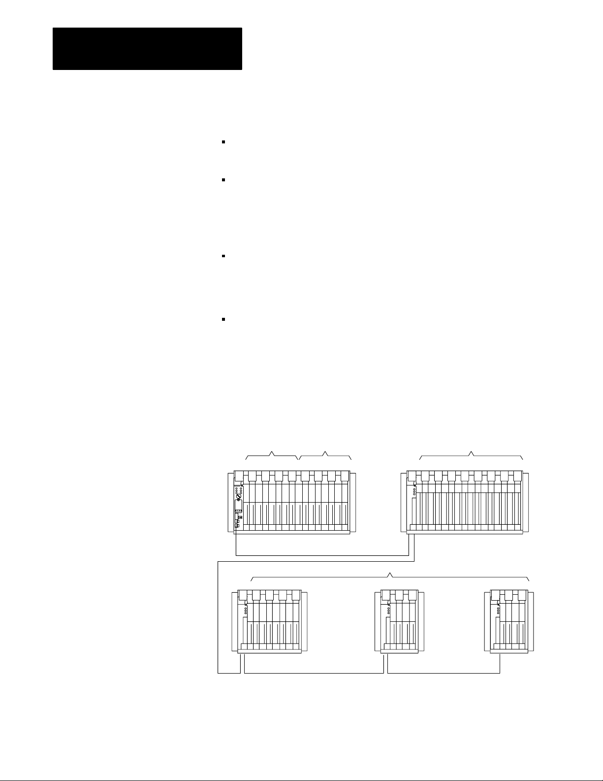
Chapter 4
Assigning Addressing Modes,
Racks, and Groups
When assigning rack numbers, use the following guidelines:
One I/O rack number is eight I/O groups, regardless of the addressing
mode that you select.
You can assign from one to four racks in your processor-resident
local chassis (128 inputs and 128 outputs) depending on the chassis
size and addressing mode. You cannot split a processor-resident local
I/O rack over two or more chassis or assign unused processor-resident
local I/O groups to remote I/O racks.
The default address of the processor-resident local rack is 0. You can
change the default to 1 by setting bit 2 in the processor control word
(S:26) on the processor configuration screen; you must also change the
mode of the processor from run to program to run.
An extended-local I/O and a remote I/O chassis cannot be addressed by
the same I/O rack number. For example, if an 8-slot extended-local I/O
chassis is configured as I/O groups 0-3 of I/O rack 2, an 8-slot remote
I/O chassis cannot be configured as I/O groups 4-7 of I/O rack 2.
Remote I/O Racks
You can assign a remote I/O rack to a fraction of a chassis, a single I/O
chassis, or multiple I/O chassis:
I/O Rack No.0 I/O Rack No.1
01 23 45 67 01 23 45 67 0123 456 7
16slot chassis, two racks
One
Power source not indicated Power source not indicated
I/O Rack No.3
5
0123
4slot chassis, 1/2 rack
One 2slot chassis, 1/4 rack each
Power source not indicated
4
Two
Power source not indicated
I/O Rack No.2
16slot chassis, one rackOne
67
16466
4-10
Page 53

Chapter 4
Assigning Addressing Modes,
Racks, and Groups
When assigning remote I/O rack numbers, use the following guidelines:
Limit the number of remote I/O rack numbers to those that your PLC-5
processor can support.
The PLC-5 processor and the 1771-ASB adapter module automatically
allocate the next higher rack number(s) to the remaining I/O groups of
the chassis. For example, if you select 1/2-slot addressing for your
processor-resident local chassis and you are using a 16-slot (1771-A4B)
chassis, the processor will address racks 0, 1, 2, and 3 in this chassis.
BlockTransfer Module Racks Using 1/2Slot Addressing
To address a block-transfer module in a 1/2-slot I/O group, use the
assigned rack number, the lower assigned I/O group number of the slot(s)
in which the module resides, and 0 for the module number (Figure 4.4).
Figure 4.4
Example
I/O Group
Number
BlockT
This example is valid for a singleslot
ransfer Module Address Using 1/2Slot Addressing
Rack 0 Rack 1 Rack 2 Rack 3
0–3 4–7 0–3 4–7 0–3 4–7 0–3 4–7
BT module only.
Rack = 2
Group = 4
Slot = 0
4-11
Page 54

Chapter 4
Assigning Addressing Modes,
Racks, and Groups
Addressing
Complementary I/O
You configure complementary I/O by assigning an I/O rack number of one
I/O chassis (primary) to another I/O chassis (complementary),
complementing modules I/O group for I/O group. The I/O modules in the
complementary chassis perform the opposite function of the corresponding
modules in the primary chassis.
The PLC-5/15 and -5/25 processors operating as a remote I/O scanner
support complementary I/O.
Use these guidelines when you configure your remote system for
complementary I/O:
Assign the complementary I/O rack number to a chassis of any size.
Do not place an input module opposite an input module; they will use
the same bits in the input image table.
You can place an output module opposite another output module; they
use the same bits in the output image table. This allows you to use one
output module to control a machine and use the other module with the
same address to control an annunciator panel to display the machine
condition. We do not, however, recommend this placement of modules
for redundant I/O.
You cannot configure the PLC-5 processor-resident local chassis with
complementary I/O. The PLC-5 processor communicates with each
processor-resident local I/O chassis as if it were a full I/O rack (eight
I/O groups). Thus, if the processor-resident local chassis contains four
I/O groups, the remaining four I/O groups of that I/O rack are unused;
you cannot assign them to another chassis.
You cannot use complementary I/O with a chassis that uses a
combination of 32-point I/O modules and 1-slot addressing or 16-point
I/O modules with 2-slot addressing.
Important: For the PLC-5/15 and -5/25 processors, an autoconfigure is
performed before the scanner begins communicating with the adapter.
Placing the Modules with 2Slot Addressing
Figure 4.5 shows a possible module placement to configure
complementary I/O using 2-slot addressing.
4-12
Page 55

Chapter 4
Assigning Addressing Modes,
Racks, and Groups
Primary 16Slot
Chassis
I/O Group
Number
Complementary
16Slot Chassis
Primary 16Slot
Chassis
I/O Group
Number
Complementary
Chassis Not
Allowed
Except for Output
Figure 4.5
Complementary
I
I
8
8
021 34567
O8O
8
O
I
16
16
02134567
Outputs in the complementary chassis use the same bits in the output image table as
the outputs in the primary chassis.
O
8
I
8I8
I16O
O
8
16
I/O Configurations with 2Slot Addressing
I
8
I
O
M
E
P
T
Y
16
O8O
O8O
8
8
1
13
16
E
M
P
T
Y
Example A
I
16
I
O
16
O
16
16
Example B
BT
E
M
P
T
Y
I
O
8
BT
2
O
8
3
O
16
16
BT
E
M
P
T
Y
Double–slotBTDouble–slot
O
16
E
E
M
M
P
T
Y
I
O
16
16
O
P
8
T
333
Y
I
O
16
16
BT
E
M
O
P
8
T
3
Y
I
O
16
16
I = Input Module O = Output Module BT = Block Transfer Module 8 = 8point I/O Modules 16 = 16 point I/O Modules
1 Output modules use the same output image transfer bits
2 Can be 8point input or output module or singleslot block transfer module
3 Must be empty if corresponding primary slot is block transfer module
13079
4-13
Page 56

Chapter 4
Assigning Addressing Modes,
Racks, and Groups
Placing the Modules with 1Slot Addressing
Figure 4.6 shows a possible module placement to configure
complementary I/O using 1-slot addressing.
Primary 16Slot
Chassis
I/O Group
Number
Complementary
16Slot Chassis
Primary 16Slot
Chassis
I/O Group
Number
Complementary
16Slot Chassis
Figure 4.6
Complementary
IIO IOO
021 34567
OO I I O OI
I
I
I
I
021 34567
O
O
O
O
I/O Configurations with 1Slot Addressing
O
BT
1
E
M
P
T
3
12
Y
Example A
I
I
I
I
O
O
O
O
Example B
Double–slot
BT
01234567
E
M
P
T
3
Y
I
01234567
O
OI I I OO
I, O,
IIIOOO
BT
I
I
I
I
I
O
O
O
O
O
I
O
I
O
4-14
I = Input Module (8 or 16point)
O = Output Module (8 or 16point)
BT = Block Transfer Module
1 Output modules use the same output image table bits
2 Can be input or output module (8 or 16point) singleslot block transfer module
3 Must be empty if corresponding primary slot is block transfer module
13080
Page 57

Chapter 4
Assigning Addressing Modes,
Racks, and Groups
Placing the Modules with 1/2Slot Addressing
Figure 4.7 shows a possible module placement to configure
complementary I/O using 1/2-slot addressing.
Figure 4.7
Complementary
Primary 12Slot
Chassis
I/O Group
Number
Complementary
12Slot Chassis
Primary 12Slot
Chassis
I/O Group
Number
Complementary
12Slot Chassis
I/O Configurations with 1/2Slot Addressing
IIO IOO
O
1
BT
Double-slot
BT
01
E
E
M
OO I I O OI
M
P
P
T
T
33
12
Y
Y
Example A
I
I
I
I
I
I
I
I
I
01 232345456767010123234545676701012323454567
O
O
O
O
O
O
O
O
O
Example B
I, O ,
BT
I
O
OI
67
IO
I
O
I
O
I = Input Module (8, 16, 32point)
O = Output Module (8, 16, 32point)
BT = Block Transfer Module
1 Output modules use the same output image table bits
2 Can be input or output module (8 or 16point) singleslot block transfer module
3 Must be empty if corresponding primary slot is block transfer module
14261
4-15
Page 58

Chapter 4
Assigning Addressing Modes,
Racks, and Groups
Placing Complementary I/O Modules
See Table 4.B for a summary of 8-, 16-, and 32-point I/O module
placement guidelines. See Table 4.C for a summary of block-transfer
module placement guidelines.
Table 4.B
Placement
Complementary I/O
Addressing
Method
Types of Modules Used: Placement
2Slot 8 point
1Slot 8 point, 16point,
1/2Slot 8 point, 16point, 32point
Table 4.C
Placement
Complementary I/O
Addressing
Method
Using singleslot modules: Using doubleslot modules:
2Slot
• The right slot of the primary I/O group can be
another singleslot block transfer module, or an
8point input or output module.
• The left slot of the complementary I/O group must be
empty.
• In the right slot of the complementary I/O group, you
can place an 8point output module; this slot must be
empty if the corresponding slot in the primary I/O
group is a singleslot block transfer module.
Summary for 8, 16, and 32point Modules Used in
Guidelines
Install input modules opposite output modules and output modules
opposite input modules.
Summary for Blocktransfer Modules Used in
BlockTransfer Placement Guidelines in Primary Chassis
• The left slot of the complementary I/O group must be
empty.
• In the right slot of the complementary I/O group, you
can only place an 8point output module (if any).
4-16
1Slot Leave the corresponding I/O group in the
complementary chassis empty.
1/2Slot Leave the corresponding I/O group in the
complementary chassis empty.
• The left slot of the two corresponding I/O slots in the
complementary chassis must be empty.
• In the right slot of the two corresponding I/O slots in
the complementary chassis, you can place an input,
output, or singleslot block transfer module (if any);
the modules can be either 8point or 16point I/O
modules.
• The left slot of the two corresponding I/O slots in the
complementary chassis must be empty.
• In the right slot of the two corresponding I/O slots in
the complementary chassis, you can place an input,
output, or singleslot block transfer module (if any);
the modules can be 8point ,16point and/or 32point
I/O modules.
Page 59

Chapter
Choosing Communication
5
Chapter
Objectives
Identifying Classic PLC5
Processor
Channels/Connectors
Use this chapter to choose the appropriate communication for
your application.
If you want to read about: Go to
Identifying channels for the processor 52
Configuring communication for
your processor
Configuring Data Highway
Plus (DH+)
Connecting DH+ to
Data Highway
Choosing programming software 5-10
Choosing programming
terminal connections
page:
53
53
510
510
This section illustrates and describes the processor front-panels. After you
are familiar with the processor hardware, see page 5-3 for information on
configuring communication.
System Design
Determined
Choosing Hardware
Placing System
Hardware
Assigning Addressing
Mode, Racks,
and Groups
Choosing
Communication
Planning Your
System Programs
Selecting Interrupt
Routines
Transferring Discrete
and Block Data
Calculating Program
Timing
5-1
Page 60

Chapter 5
Choosing Communication
Figure 5.1
Processor
PLC5/10 Processor PLC5/12, 5/15,
Communication
Indicator
ACTIVE/FAULT
(green/red)
Keyswitch
Connect
programming
terminal here
Connect
DH+
link here
Front Panels
Battery
Indicator (red)
Processor
RUN/FAULT
Indicator
(green/red)
FORCE
Indicator
(amber)
Battery
Holder
Write the DH+
network station
number on this label
PLC5 family
member
designation
and 5/25 Processors
REM I/O Indicator
ACTIVE/FAULT
(green/red)
Adapter
Indicator
(green)
Connect
remote
I/O link here
P
R
O
G
Connector Name Connector
Description
Type
Programming terminal 9pin, Dshell Use this connector to directly connect a programming terminal to the processor. This programming
terminal connector has a parallel connection with the 3pin DH+ communications link connector.
DH+ communications link 3pin Use this connector to connect to DH+ communications link.
Remote I/O 3pin Use this connector for the remote I/O link. (This connector is not available for a PLC5/10 processor.)
5-2
Page 61

Chapter 5
Choosing Communication
Configuring Communication
for Your Processor
You select scanner or adapter mode for your PLC-5 processor by setting
switches.
Configure Processor Communication
You configure the processor by setting switch assemblies SW1 and SW2
on the processor. See Appendix A for information on switch settings.
Follow these steps to plan configuration for your processor.
1. Select scanner or adapter mode on switch assembly SW1 (the
PLC-5/10 and -5/12 can not be configured as scanners).
2. If you select adapter mode, assign a rack address (rack number 0-77
octal) on switch assembly SW2. The supervisory processor uses this
address to reference the adapter-mode processor.
3. If you select adapter mode, specify the simulated chassis size, either
an 8-slot or 16-slot I/O chassis, and the corresponding first I/O group
on switch assembly SW2. The simulated chassis size and first I/O
group determine the number of discrete-transfer data words (4 words
for an 8-slot chassis, 8 words for a 16-slot chassis) that the processor
transfers to and from the supervisory processor during the
supervisory processor’s remote I/O scan.
Configuring a DH+ Link
Note that the actual size of the chassis has no bearing on the
simulated size of the chassis.
You can use a DH+ link for data transfer to higher level computers and as a
multiple PLC-5 processor programming link. A PLC-5 processor can
communicate over a DH+ link with other processors and with a
programming terminal. You can connect a maximum of 64 stations to a
DH+ link. The network operates under a token-passing protocol with data
transfer at 57.6 kbps.
See your programming software documentation set to configure a
processor for DH+ communication.
Estimating Data Highway Plus Link Performance
Many factors can affect the performance of your DH+ link, including:
nodes
size and number of messages
message destination
internal processing time
5-3
Page 62

Chapter 5
Choosing Communication
Nodes
Nodes affect transmission time in the following ways:
During one complete token rotation, each node on the DH+ link
receives the token whether or not it has something to send.
Each node spends from 1.5 ms (if it has no messages to send) to 38 ms
(maximum time allotted) with the token, assuming there are no retries
(Figure 5.2).
Figure 5.2
Token
Passing
Station
Min.
1.5 ms
the token
with
1
DH+ link
Station
5
Station
4
Station
3
Station
2
Max. 38 ms
with the token
Size and Number of Messages
A PLC-5 processor encodes messages into packets for transmission on the
DH+ link. The maximum number of data words in a packet depends on
the sending station and command type. This limit comes from the network
protocol, which limits a station to transmitting a maximum of 271 bytes
per token pass. A station can send more than one message in a token pass,
provided that the total number of combined command and data bytes does
not exceed 271.
If a message exceeds the maximum packet size allotted, however, the
sending station will require more than one token pass to complete the
message. For example, if a PLC-5 processor wants to send a 150-word
message, it will have to transmit two messages, possibly requiring many
token rotations.
5-4
The number of messages a station has to send also affects throughput time.
For example, if a station has three messages queued and a fourth is
enabled, the fourth message may have to wait until the previous three
are processed.
Page 63

Chapter 5
Choosing Communication
Message Destination
Throughput times vary depending on whether a receiving station can
process the message and generate a reply before that station receives the
token. Figure 5.3 assumes that station 1 wants to send a message to
station 4.
Figure 5.3
Message
DestinationExample 1
Station
5
Message
Station
4
Station
1
Station
2
Station 1 has the token. Only the station that has the token can send a
message. Station 1 sends the message to station 4. Now station 1 must
pass the token on to the next highest station number, which is station 2.
Station 2 has the token. Assume that station 2 has messages to send and
holds the token for 30 ms. During this time, station 4 has processed the
message from station 1 and has a reply queued up. When finished, station
2 passes the token on to the next highest station number, which is station 4.
Station 4 can now reply to the message from station 1. This completes the
message transaction.
In Figure 5.3, station 4 has had time to process the message and generate a
reply. But, that is not the case with station 2 in Figure 5.4.
Figure 5.4
Message
DestinationExample 2
Station
5
Station
4
Station
1
Message
Station
2
5-5
Page 64

Chapter 5
Choosing Communication
In Figure 5.4, we assume that station 1 wants to send the identical message
as shown in Figure 5.3 but to station 2. Station 1 has the token. Station 1
sends the message to station 2 and then passes the token on to station 2.
Now station 2 has the token but has not had time to generate a reply to
station 1. So station 2 sends any other messages it has queued and then
passes the token on to station 4. Stations 4, 5, and 1 all receive the token
in order and send any messages they have queued. The token then returns
to station 2, which then sends its reply to station 1. In this example, it took
an extra token pass around the network to complete the message
transaction even though the message was identical to the one shown in
Figure 5.3.
Internal Processing Time
Internal processing time depends on how busy a given processor on the
network is when sending or receiving a message.
For example, processor A has just received a READ request from
processor B on the network. If processor A already has three messages of
its own to send, the reply to the READ request from processor B will have
to wait until the station completes the processing of the messages queued
ahead of it.
Average DH+ Link Response Time Test Results
This section shows graphically the results of testing performed on a DH+
link where the number of stations and words sent in the message varies.
Figure 5.5 shows the average response time of messages of varying sizes
on a DH+ link with a varying numbers of stations. It also gives you an
idea of the typical response time you can expect on a given DH+ link.
5-6
Page 65

Chapter 5
Choosing Communication
Response
Time
(Sec)
Figure 5.5
Average
5.0
4.5
4.0
3.5
3.0
2.5
2.0
1.5
1.0
0.5
0.0
1 2 3 4 5 6 7 8 9 10 11 12 13 14 15 16 17 18 19 20 21 22
Response T
Number of PLC5 Processors
ime for all PLC5 Processors
Figure 5.6 shows the effect of a programming terminal on message
response time under various configurations.
40
Figure 5.6
Response
%
T
ime Increase (%)
50 W
100 W
•
+
250 W
X
500 W
W=Words
Effect
on
Response
Time
(%)
%
35
%
30
%
25
%
20
%
15
%
10
5
%
0
%
1 2 3 4 5 6 7 8 9 10111213141516171819202122
Number of PLC5 Processors
Test Setup
One to 22 PLC-5 processors were used with one programming terminal
online. Each PLC-5 processor executes 1K of ladder logic.
X
50 W
100 W
•
+
250 W
500 W
W=Words
5-7
Page 66

Chapter 5
Choosing Communication
Initial testing was done with one PLC-5 processor writing data to another
PLC-5 processor. The response time was recorded. Additional PLC-5
processors were added to the network, each writing the same amount of
data to a PLC-5 processor at the next highest station address. Four
separate tests were run using data transmissions of 50, 100, 250, and
500 words.
Application Guidelines
Consider the following application guidelines when configuring a DH+
link for your system.
Configure the number of nodes on your network dependent on the size
and frequency of messages exchanged between devices.
Limit the number of nodes on your network when you are trying to
achieve fastest control response time.
Do not add or remove nodes from the network during machine or
process operation. If the network token resides with a device that is
removed, the token may be lost to the rest of the network. The network
is automatically re-established, but it could take several seconds.
Control would be unreliable or interrupted during this time.
Include watchdog timers in logic programs for DH+ transfer of data (to
provide an orderly shutdown if failure occurs).
Do not program processors online during machine or process operation.
This could result in long bursts of DH+ activity that could increase
response time.
When possible, add a separate DH+ link for programming processors to
keep effects of the programming terminal from the process DH+ link.
Connecting Devices to DH+ Link
You can connect devices on a DH+ link with:
daisy-chain connection
trunkline/dropline connection
5-8
See Figure 5.7. Also, see the Data Highway and Data Highway Plus Cable
Guide, publication 1770-6.2.1, for complete network wiring instructions.
Page 67

Chapter 5
Choosing Communication
PLC5 PLC5 PLC5 PLC5
Daisychain configuration
PLC5 PLC5 PLC5
Figure 5.7
Examples
of DH+ Link Connections (DaisyChain and
Trunkline/Dropline)
T50
1
SH
2
When the processor is an end
device, terminate the link.
Station connector (see notes)
Trunkline/dropline configuration
T50
Notes:
Once a programming terminal is connected to one processor, it can
communicate with each processor you connect on DH+.
Use only AllenBradley station connectors.
13061
5-9
Page 68

Chapter 5
Choosing Communication
The PLC-5 processor has two connectors that are electrically identical.
Connection to either one provides the same communication link. These
connectors are:
9-pin D-shell DH+ COMM INTFC connector
3-pin DH+ COMM INTFC connector
Connecting a DH+ Link
to Data Highway
Choosing Programming
Terminal Connection
You can connect DH+ links to Data Highway via a communication
interface such as the 1785-KA module. The 1785-KA module allows
nodes on a DH+ link to communicate with nodes on Data Highway or on
another DH+ link.
See your local Allen-Bradley sales office or distributor for more
information on connecting DH+ to Data Highway. Also, see the Data
Highway/Data Highway Plus Protocol and Command Set, publication
1770-6.5.16, for more information.
You can connect your programming terminal to a PLC-5 processor in
several ways:
direct connect to the DH+ link
remote connection (DH+ to Data Highway to DH+)
serial connections
Direct Connect to DH+ Link
Use a 1784-KT to connect a T53 or IBM-compatible programming
terminal directly to a processor or to a DH+ link that connects processors
(Figure 5.8).
5-10
Page 69

Chapter 5
Choosing Communication
Figure 5.8
Connection
to DH+ Link through 1784KT Communication
Interface Module
DH+ link
1784CP
T53 or IBM compatible
with 1784KT
PLC5/10,
or 5/25 processor
5/12 5/15,
Use a 1784-KL/B to connect a T47 programming terminal directly to a
processor or to a DH+ link that connects processors (Figure 5.9).
Figure 5.9
Connection
Interface Module
to DH+ Link through 1784KL Communication
DH+ link
1784CP
T47 with 1784KL
PLC5/10,
or 5/25 processor
5/12,
5/15,
Remote Connection
The remote programming configurations available with the 1784-KT,
1784-KT2, and 1784-KL boards provide you communication with
processors on other DH+ links in the network to expand the range of
processors that you can use for program development (Figure 5.10).
5-11
Page 70

Chapter 5
Choosing Communication
Figure 5.10
Example
DH+ to Data Highway to DH+ Link Configuration
1785KA
Data Highway
Remote DH+ link
PLC5/10, 5/12, 5/15, 5/25
processor
17195
Serial Connections
You can connect a programming terminal to a PLC-5/10, -5/12, -5/15, or
-5/25 processor through a serial port (COM1 or COM2) on the terminal
with one of the following communication modules:
1785-KE Series A or B Communication Interface Module
(resides in a 1771 I/O rack)
1770-KF2, Series B Communication Interface Module
(desktop unit as shown in Figure 5.12)
Important: The communication driver is interrupt-driven; the serial port
must support hardware interrupts. On most machines, COM1 and COM2
support these interrupts.
5-12
Page 71

Chapter 5
Choosing Communication
Figure 5.11
1785KE
(Series B) Connection through an RS232C Serial Port
DH+ link
T53 serial port
COM1 or COM2
Figure 5.12
1770KF2/B
1785KE Series B
PLC5/10, 5/12, 5/15, or
5/25 processor
Connection through an RS232C Serial Port
DH+ link
T53 serial port
COM1 or COM2
1770KF2/B
PLC5/10, 5/12, 5/15, or
5/25 processor
5-13
Page 72

Chapter
6
Planning Your System Programs
Chapter
Objectives
This chapter covers basic programming considerations for planning a
Classic PLC-5 programmable controller system.
System Design
Determined
If you want to read about: Go to
Planning application programs 61
Using SFCs 61
Preparing programs for
your application
Addressing the data table 67
Using the processor status file 69
See your programming software documentation for a discussion of the
instructions used in ladder-logic programming.
page:
63
Choosing Hardware
Placing System
Hardware
Assigning Addressing
Mode, Racks,
and Groups
Choosing
Communication
Planning Your
System Programs
Selecting Interrupt
Routines
Transferring Discrete
and Block Data
Calculating Program
Timing
Planning Application
Programs
Using SFCs with
PLC5 Processors
Use the functional specification that you previously developed to define
your programming application. The specification is a conceptual view of
your application and is used to determine your main program, sequential
function chart (SFC), and logic requirements.
In planning and developing the programs for your application, we
recommend that you use the program-development model shown in
chapter 1, “Understanding Your System.”
Use SFCs as a sequence-control language by which you can control and
display the state of a control process. Instead of one long program for
your application, divide the logic into steps and transitions. The display of
these steps and transitions lets the user see what state the machine process
is in at a given time.
6-1
Page 73

Chapter 6
Planning Your System Programs
008
012
002
Initial
Step
003
Each step corresponds to a control task (displayed as a box); each step is
related to a program file that contains the logic for the associated control
task. Each transition (displayed as a horizontal line) examines conditions,
specified in an associated program file, that determines when the processor
007
011
005
can continue to the next task.
Deciding How to Use an SFC
After you identify the major areas of machine operation, convert the
004
006
009
010
logical paths and steps that you labeled in your design specification to SFC
013
014
015
If you have: Then draw: Using these rules:
An independent machine state A step with its transition A step must always be followed by a transition.
building blocks. Table 6.A helps explain when to use which SFC
building blocks.
Important: At this point, do not worry about the actual logic for each step
and transition. After you complete the SFC, you can develop the logic.
Table 6.A
Deciding
When to Use the SFC Structures
A clearly defined chain of events that
occur sequentially
For example, in one heattreating
area, the temperature must ramp up
at a particular rate; maintain the
temperature for a certain duration,
then cool at a particular rate.
Two or more alternative paths where
only one is selected
For example, depending on a build
code, one station must either drill or
polish.
Two or more parallel paths that must
be scanned simultaneously at
least once
For example, communications and
block transfers must occur while
control logic is executing.
A simple path of steps
and transitions
A selection branch The transitions beginning each path are scanned from left
A simultaneous branch All paths are active in the structure.
For design purposes, number steps and transitions
consecutively from 2.
Start the path with a step; end the path with a transition.
to right. The first true transition determines the path taken.
You can define up to 7 parallel paths.
6-2
Page 74

Chapter 6
Planning Your System Programs
Application Example for SFCs
For typical SFC applications, an SFC program controls the order of events
in your process by issuing commands. A command, such as
fwdcyr_cmd
to move a conveyor forward, is simply a data table storage bit (for example
B3:0/7) that you set up in the SFC. You then program the logic for
fwdcyr_cmd in a separate ladder program to control the actual outputs to
move the conveyor.
You can have only one main program file, which is either an SFC or a
ladder-logic program. You enter the programs into your computer using the
SFC or ladder editor. For more information on entering SFCs or ladder
logic, see your programming software documentation set.
Programming Considerations for SFCs
Use the information in Table 6.B for SFC rules for special programming.
Preparing the Programs
for Your Application
Table 6.B
Rules for Special Programming Considerations
SFC
If you have: Use these rules:
To jump within the SFC Use a GOTO statement and label.
A step that needs to be run in
multiple places within the SFC
A step that can be ignored based on
logic conditions
An SFC branch structure within
another branch structure (nesting)
A miniSFC (compressed steps)
within the main SFC
To reset the logic in an SFC program Set the SFR instruction to reset the chart.
To disable an MCP Set the disable bit on the Processor Configuration screen.
See your programming software documentation for further information on any of the techniques listed in this table.
Repeat the step where needed or use a global subroutine that gets called
from multiple steps.
Create two selection branches, one with and one without the step; or
place the step in a subroutine; or combine the step with another step that
is segregated by an MCR zone.
Nest the branch structures. The software supports as many levels of
nested branches as you can store based on processor memory.
Create an SFC macro. A macro begins a with a step; the transition for the
ending step follows the macro.
This section uses a drill-machine application example. Information on the
program entry phase is in the programming software documentation set.
You can use only one main program; but you can still apply some of
the steps by incorporating them into your main SFC and supporting
ladder programs.
6-3
Page 75

Chapter 6
Planning Your System Programs
FWD
AUTO
Organizing a Machine Example
This section uses an example of a specific machine operation to show how
to identify conditions and actions and how to group the actions into steps
of machine operation.
Figure 6.1
Hardware
OFF
Block Diagram and Description of Machine Process
L oad
St a t i on
FWD
FWD
Conveyor
Motor
Advance
Assembly
NC
..
LS2
Held Open
A description of this operation might be as follows:
1. The operator starts the conveyor by selecting AUTO.
2. The operator puts a block of wood onto the conveyor.
3. The wood moves into position and actuates LS1.
4. When the wood is in position:
a. the conveyor stops
b. CL1 clamps the wood
c. the drill station moves forward
5. The drill station moves forward and closes LS3. This
action turns on the drill motor.
Drill
Motor
LS1
..
NO
.. ..
NO NO
6. The drill station moves to full depth and closes LS4. This action:
a. stops forward motion of the drill station
b. initiates a 2second dwell
7. The drill station backs up after the 2second dwell.
8. The drill motor stops when LS3 is released.
9. The drill station reaches home position and opens LS2. This action:
a. stops the reverse motion
b. opens the clamp
c. starts the conveyor forward
10. The wood is ejected when LS5 toggles to indicate that the cycle is complete.
LS4LS3
LS5
..
NO
load
Un
St a t i on
Clamp
CL1
6-4
Page 76

Chapter 6
Planning Your System Programs
We recommend that you then create a rough-draft SFC to represent the
operation (see Figure 6.2).
Figure 6.2
Machine Example Functional Specification
Drill
Step
Transition
initialization
010 AUTO operator starts cycle
conveyor forward
011 LS1 wood in position
drill
012 LS4 hole drilled
dwell
013 TMR1 dwell timer done
reverse drill
014 LS2 station home
eject
015 LS5 wood ejected
Creating the Detailed Analysis for Your Functional Specification
Begin determining the details of your process as discussed in chapter 1,
“Understanding Your System.” Identify the hardware requirements.
Table 6.C identifies hardware requirements for the inputs and outputs of
the drill machine.
6-5
Page 77

Chapter 6
Planning Your System Programs
Table 6.C
Hardware
Input Part Description
AUTO selector switch select automatic mode
LS1 N.O. limit switch part in place
LS2 N.C. limit switch drill station home
LS3 N.O. limit switch drill motor on
LS4 N.O. limit switch drill station at full depth
LS5 N.O. limit switch cycle complete
DSF drive motor move drill station forward
DSB drive motor move drill station back
DM drill motor drill motor on
CL1 electric clamp clamp 1 on
CMF drive motor move conveyor forward
TMR1 timer dwell timer
Requirements for the Inputs and Output of the Drill Example
Use the hardware requirements (with the functional specification) to
match the inputs and outputs with the actions of the process. Table 6.D
shows the hardware requirements with the general description of the drill
machine example.
Table 6.D
of Conditions and Actions for the Drill Example
List
When this happens: This happens:
AUTO switch closes Conveyor moves forward (CMF = on)
LS1 closes Conveyor stops
Clamp holds wood
Drill station advances
LS3 closes Drill motor starts (DM = on)
LS4 closes Drill station stops
Dwell timer starts
Timer done Drill station backs up (DSB = on)
LS3 opens Drill motor stop (DM = off)
LS2 opens Drill station stops
Clamp releases wood
Conveyor starts
LS5 closes Wood is ejected
(CMF = off)
(CL1 = on)
(DSF = on)
(DSF = off)
(TMR1 = on)
(DSB = off)
(CL1 = off)
(CMF = on)
6-6
Page 78

Chapter 6
Planning Your System Programs
Once you identify the individual actions, you can add these actions to
your plan to complete your program. Once you have an SFC program that
defines the individual machine actions for your process, you can create a
ladder-logic program that controls the outputs of those machine actions. It
does not matter in what order you program these rungs. This program
merely contains the ladder logic that defines a command for each machine
action in your process.
Program Entry
When you finish your detailed analysis, you have your main program
planned. Now, enter your program into your terminal.
Addressing Data T
Input Output
ExamineData ReturnResults
DATA STORAGE
I/O Image Files
BlockTransfer Files
Other Data Files
PROGRAM FILES
able Files
DataData
PLC-5 memory is divided into two areas: data and program-file storage.
Areas of Storage Description
Data All of the data the processor examines or changes is stored in files in data
storage areas of memory. These storage areas store:
•Data received from input modules
•Data to be sent to output modules; this data represents decisions made
by the logic
•Intermediate results made by the logic
•Preloaded data such as presets and recipes
•Control instructions
•System status
Program Files You create files for program logic, depending on the method you are using:
ladder logic, sequential function charts, and/or structured text. These files
contain the instructions to examine inputs and outputs and return results.
Data Table Memory
You can address data files in different formats when you write your
programs. Refer to Table 6.E for valid data table file-type specifications.
6-7
Page 79

Chapter 6
Planning Your System Programs
Table 6.E
T
able Memory Usage
Data
Memory Used in Over
File Type
Output Image O 0 2 1/word
Input Image I 1 2 1/word
Status S 2 2 1/word
Bit (binary) B 3 2 1/word
Timer T 4
Counter C 5
Control R 6
Integer N 7
FloatingPoint F 8
ASCII A 3999 2
BCD D 3999 2 1/word
Undefined 9999 2 0
1
This
is the default file number
File Type
Identifier
. For this file type, you can assign any file number from 3 thru 999.
File
Number
1
1
1
1
1
head for Each File
(16bit words)
2 3/structure
2 3/structure
2 3/structure
2 1/word
2 2/float word
Memory Used
(16bit words) per
Word, Float Word,
Character, or Structure
1
/2 per character
Data table files are contiguous in memory. Size in words for I/O files
0 and 1 are:
For this processor: Files O0 and I1 memory size:
PLC5/10, 5/12, 5/15 Is fixed at 32 words
PLC5/25 Varies from 3264 words (32 is the default)
6-8
Status file 2 is fixed at 32 words for each processor. Files 3-999 vary in
size. These files contain only the number of words corresponding to the
highest address that you assign. Each B, N, A, and D file can be 1,000
words maximum. Each F file can be 1,000 float words (32-bit words)
maximum. Each T, C, R, and SC file can be 1,000 structures maximum.
Page 80

Data Table Addressing Formats
Address Type Description Example
Chapter 6
Planning Your System Programs
Logical address Alphanumeric coded format to specify
the data location
I/O image address Logical address format, but relates
physical locations in the I/O chassis to
memory locations in the I/O image file
Indirect address Logical address format, but allows you to
change address values in the base
address with your ladder logic program
Indexed address Index prefix (#) is followed by a logical
address format, but it adds an index
value (offset) from processor status file
to the base address
Symbolic address ASCII character string that relates the
address (file, structure, word, or bit) to a
descriptive, meaningful name that you
assign
Using
the Processor
Status File
Use the Processor Status screen to monitor:
processor status information
major and minor faults
STIs
program scan times
I/O status
N23:0 addresses an integer file 23, word 0
I:017/17 addresses input file word 017 (octal), bit 17 (octal), which corresponds to
rack 01, module group 7, and terminal 17
N[N7:6]:0 has the file number as the variable
The file number is stored in integer file 7, word 6
When #N23:0 is the indexed address and the offset value stored in the processor
status file is 10, then
•the base address is integer file 23, word 0
•and the offset address is integer file 23, word 10
For example, a floating point address F10:0 could be given a symbolic address of
Calc_1. These symbols are a feature of the programming software and not of the
processor. Guidelines for setting up an address are as follows:
•Start the name with an alphabetic character.
•The symbol must begin with a letter and can have up to 10 of the following
characters: AZ (upper and lower case), 09, underscore (_) and @.
•You can substitute a symbolic address for structure, word, or bit addresses.
•Record the symbols you define and their corresponding logical addresses.
Processor status data is stored in status file S2. See Table 6.F.
6-9
Page 81

Chapter 6
Planning Your System Programs
Table 6.F
Processor
This word of the status file: Stores:
Arithmetic flags
S:0
S:1
S:2
S:3 to S:6
S:8 Last program scan duration (in ms)
S:9 Maximum program scan duration (in ms)
S:10 Minor fault bits
S:11 Major fault bits
S:12 Fault code storage location
S:13 Program file where fault occurred
S:14 Rung number where fault occurred
S:16 I/O status file number storage location
S:18
S:19 Processor clock month
S:20 Processor clock day
S:21 Processor clock hour
S:22 Processor clock minute
S:23 Processor clock second
S:24 Indexed addressing offset
S:25 (PLC5/12, 5/15, 5/25 only) I/O adapter image file
S:26 User control bits for processor startup routine
• bit 0= carry
• bit 1 = overflow
• bit 2= zero
• bit 3 = sign
Processor status and flags
Switch settings:
• bits 0 5 = DH+ station #
• bit 7 = set is scanner; reset is adapter (PLC5/15, 5/25 only)
• bit 11, 12 = HW addressing
• bit 13, 14 = EEPROM
• bit 15 = set is memory unprotected
Active Node table:
Word Bits DH+ Station #
3 015 0017
4 015 2037
5 015 4057
6 015 6077
Processor clock year
Status File Addresses
bit 12
0 0 illegal
1 0 1/2slot
0 1 1slot
1 1 2slot
bit 13
0 0 EEPROM transfer if processor memory bad
0 1 EEPROM transfer disabled
1 1 EEPROM transfer at powerup
bit 11
bit 14
6-10
Page 82

This word of the status file: Stores:
S:28 Program watchdog setpoint (in ms)
S:29 Fault routine file
S:30 STI setpoint (in ms)
S:31 STI file number
Chapter 6
Planning Your System Programs
6-11
Page 83

Chapter
Selecting Interrupt Routines
7
Chapter
Objectives
Using Programming
Features
This chapter covers interrupt routines that you can choose to include when
you program your system.
System Design
Determined
If you want to read about: Go to
page:
Using programming features 71
Writing a fault routine 73
Choosing Hardware
Placing System
Hardware
Assigning Addressing
Mode, Racks,
and Groups
Choosing
Communication
Planning Your
System Programs
Selecting Interrupt
Routines
Transferring Discrete
and Block Data
Calculating Program
Timing
Use your design specification to determine if you need one or more of the
following programming features:
If a portion of logic
should execute:
Immediately on
detecting conditions
that require a startup
Immediately on
detecting a major fault
Example:
Restart the system
after the system has
been shut down
Send critical status
to a supervisory
processor via DH+
after detecting a
major fault
program execution control
power-up routines
Use: By doing the following:
Powerup/Fault
Routine
Fault Routine Create a separate file for a controlled response to a major fault. The first fault
Create a separate file for a controlled startup procedure for the first time that you
start a program or when you start a program after system down time. The
processor executes the powerup/fault routine to completion.
detected determines which fault routine is executed. The processor executes the
fault routine to completion. If the routine clears the fault, the processor resumes
the main logic program where it was interrupted. If not, the processor faults and
switches to program mode.
7-1
Page 84
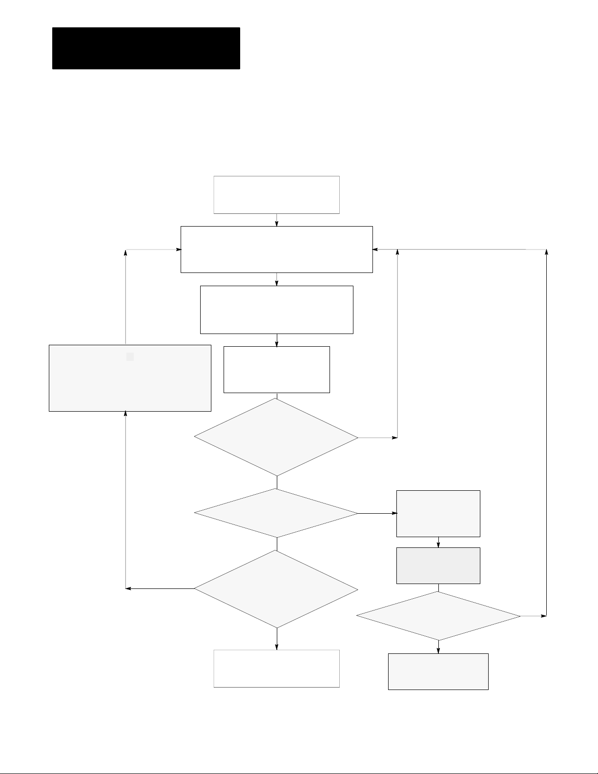
Chapter 7
Selecting Interrupt Routines
Program Execution States
User programs in the Classic PLC-5 processor are always in one of the
following five states: completed, ready, executing, waiting, or faulted.
Completed State
Program has completed execution
or has not yet started execution
Ready State
Program would be executing if it were of a higher priority;
all programs pass through this state; there can be
several programs in this state at any given time
Rescheduling Operation
Waiting State
While block transfer is taking place,
a rescheduling operation is performed
and lowerpriority programs are executed
(unless all other executions are prohibited by
a UID/UIE zone around the block transfer)
Yes
Waiting State
Program is ready for execution but is waiting
for some event to occur (such as an input to
transition or a timer to complete)
Executing State
Program is executing; only
one program can be in this
state at one time
Has a new program
with a higher priority
become ready?
(e.g., an MCP, STI, PII)
No
Does the program fault?
No
Does the program request
a remote block transfer?
(STI and PII routines only)
No
Completed State
Program has completed execution
or has not yet started execution
Rescheduling Operation
Yes
Yes
Does an appropriate fault routine
Faulted State
A runtime error
has occurred within
the program
Program counter is
adjusted to point to
next instruction
choose to clear the fault?
No
All active user programs
are aborted and processor
enters faulted state
Rescheduling Operation
Yes
7-2
Page 85

Chapter 7
Selecting Interrupt Routines
Writing a Fault Routine
You can write a fault routine that the processor runs when it detects a
major fault. For example, if your program file becomes corrupted, you can
tell the processor to interrupt the current program, run your fault routine
and then continue processing the original program.
This section shows you how to set and write a fault routine and how to
protect your processor from powering up in run mode after a power loss.
Responses to a Major Fault
When the processor detects a major fault, the processor immediately
interrupts the current program. If a fault routine exists (i.e., specified in
S:29 as a fault routine), the processor runs that fault routine program for
recoverable faults. Then, depending on the type of fault, the processor:
returns to the current ladder program file if the processor can recover
from the fault
enters fault mode if the processor cannot recover from the fault
For example, the rung in Figure 7.3 includes an instruction that causes
a major fault.
Figure 7.3
Ladder Logic for a Fault
Sample
A
][
B
Causes a
major fault
C
In the example in Figure 7.3, the processor runs the fault routine after
detecting the fault. If the fault routine resets the faulted bits, the processor
returns to the next instruction in the program file that follows the one that
faulted and outputs on the remainder of the rung.
If you do not program a fault routine for fault B, the processor
immediately faults.
The bits in word 11 of the processor status file indicate the type of major
fault. See Table 7.G to determine whether a fault is recoverable.
7-3
Page 86

Chapter 7
Selecting Interrupt Routines
Table 7.G
Response
This
00 Corrupted program file
01 Corrupted address in ladder program (see fault codes 1019)
02 Programming error (see fault codes 2029)
05 Startup protection fault (see word 26, bit 1)
07 Usergenerated fault; processor jumped to fault routine
08 Watchdog faulted
13 STI file does not contain ladder logic or does not exist
03 Processor detected an SFC fault (see fault codes 7479)
04 Processor detected an error when assembling a ladder
09 System is configured wrong; you installed a RAM cartridge but
10 Nonrecoverable hardware error
14 Fault routine does not contain ladder logic or does not exist
15 Fault routine program file does not contain ladder logic
to Major Faults (W
bit:
Indicates this fault: And the fault is:
Processor sets bit 5; if your fault routine does not reset this bit,
the processor inhibits startup
(see fault codes 09)
program file (see fault code 70)
configured the system for an EEPROM or you violated 32point
I/O module placement rules for 1slot addressing
ord 11 of the Status File)
Recoverable
hfl i
the fault routine
can instruct the
processor to clear
the fault and then
the fault and then
resume scanning
pg
the program.
Notrecoverable
Not recoverable
the processor
enters fault mode
without scanning
without scanning
the fault routine.
A remote block transfer from a fault routine causes the processor to stop
scanning all programs until the block transfer completes.
Major Fault Codes
Table 7.H lists major fault codes. The processor stores the fault code in
word 12 of the processor status file.
7-4
Page 87

Chapter 7
Selecting Interrupt Routines
Table 7.H
Fault Codes
Major
Code Fault
0009 Reserved for userdefined fault codes
12 Bad integer operand type, restore new processor memory file
13 Bad mixed mode operation type, restore new processor memory file
14 Not enough operands for instruction, restore new processor memory file
15 Too many operands for instructions, restore new processor memory file
16 Corrupted instruction, probably due to restoring an incompatible processor memory file
17 Can't find expression end; restore new processor memory file
18 Missing end of edit zone; restore new processor memory file
20 You entered too large an element number in an indirect address
21 You entered a negative element number in an indirect address
22 You tried to access an undefined program file
23 You used a negative file number, you used a file number greater than the number of existing files, or
you tried to indirectly address files 0, 1, or 2
24 You tried to indirectly address a file of the wrong type
30 You tried to jump to one too many nested subroutine files
31 You did not enter enough subroutine parameters
32 You jumped to an invalid (nonladder) file
1
33
34 You entered a negative preset or accumulated value in a timer instruction
35 You entered a negative time variable in a PID instruction
36 You entered an outofrange setpoint in a PID instruction
37 You addressed an invalid module in a block transfer, immediate input, or immediate output instruction
38 You entered a return instruction from a nonsubroutine file
39 FOR instruction with missing NXT
40 The control file is too small for the PID, BTR, BTW, or MSG instruction
41 NXT instruction with missing FOR
42 You tried to jump to a deleted label
4469 Reserved
70 The processor detected duplicate labels
74 SFC file error detected
75 The SFC has too many active functions
77 SFC missing file or of wrong type for step, action, transition; or
78 The processor cannot continue to run the SFC after power loss
79 You tried to download an SFC to a processor that cannot run SFCs; or
80 You incorrectly installed a 32point I/O module in a 1slot configuration (PLC5/15, 5/25)
81 You illegally set an I/O chassis backplane switch; either switch 4 or 5 must be off
You entered a CAR routine file that is not 68000 code
Subchart is created but empty; or
SC or timer file specified in SFC empty or too small
This specific PLC does not support this enhanced SFC
7-5
Page 88

Chapter 7
Selecting Interrupt Routines
Important: If the PLC-5 processor detects a fault in the fault routine
(double fault condition), the PLC-5 processor goes directly to fault mode
without completing the fault routine.
Programming a Fault Routine
If you choose to program a fault routine, first have the fault routine
examine the major fault information recorded by the PLC-5 processor and
decide whether to do the following before the PLC-5 processor
automatically goes to fault mode:
set an alarm
clear the fault
shutdown in an orderly manner
On detecting a major fault, the PLC-5 processor immediately suspends the
program file it was running and, if programmed, runs the fault routine file
once to completion. If the PLC-5 processor does not run a fault routine, or
the fault routine does not clear the fault, the PLC-5 processor automatically
switches to fault mode.
Set an Alarm
You may need an alarm to signal when a major fault occurs. Put this rung
first in your fault routine program
alarm
output
and combine it with a counter. You can also set an alarm in your fault
routine to signal when the fault routine clears a major fault.
Clearing the Fault
If you decide to clear the fault in the fault routine, place the ladder logic
for clearing the fault at the beginning of the fault routine. You can
compare the fault code with a reference.
Compare fault code with a reference—Identify the possible major faults
and then select only those your application will let you safely clear. These
are your reference fault codes.
From the fault routine, examine the major fault code that the processor
stores in S:12. Use an FSC instruction to compare the fault code to the
reference file that contains “acceptable” fault codes (word-to-file
comparison). If the processor finds a match, the FSC instruction sets the
found (.FD) bit in the specified control structure. Use a MOV instruction
to clear the fault in S:11. Then jump to the end of the fault routine to
quickly complete running the fault routine.
7-6
Page 89

Chapter 7
Selecting Interrupt Routines
In Figure 7.4, #N10:0 is the reference file.
Figure 7.4
Example
Last rung in fault routine
of Comparing a Major Fault Code with a Reference
R6:0
][
FD
FSC
FILE SEARCH/COMPARE
Control
Length
Position
Mode
Expression
S:12 = #N10:0
MOV
MOVE
Source
Dest
S:11
0
R6:0
20
ALL
R6:0
RES
R6:0
U
IN
EN
DN
0
ER
10
JMP
10
][LBL
TND
The processor completes the scan of the fault routine. If the routine clears
S:11, the processor returns to the program file and resumes program
execution. If the fault routine does not clear S:11, the processor executes
the rest of the fault routine and goes into FAULTED mode.
Important: If the fault routine clears the major fault, the processor
completes the fault routine and returns to the next instruction in the
program file that follows the one that contained the faulted instruction.
The remainder of the rung is executed. It appears that the fault never
occurred. The fault routine execution continues until you correct the
cause of the fault.
7-7
Page 90

Chapter 7
Selecting Interrupt Routines
Using Shutdown Logic
Shutdown programming should include the following considerations.
Store initial conditions and reset other data to achieve an orderly
start-up later.
Monitor the shutdown of critical outputs. Use looping if needed to
extend the single fault routine scan time up to the limit of the
processor watchdog timer so that your program can confirm that critical
events took place.
Testing a Fault Routine
To test a fault routine, use a JSR instruction to jump to the fault routine.
Send a fault code as the first input parameter of the JSR instruction. The
processor stores the fault code in status word 12 and sets the corresponding
bit in word 11.
You may detect and set your own faults using fault codes 0-9 or by using
the processor-defined fault codes 10-87.
Setting Up a Fault Routine
You can write multiple fault routine programs and store them in multiple
fault routine files, but the logic processor runs only one fault routine
program when the PLC-5 processor detects a major fault. The number of
the fault routine the PLC-5 processor runs is stored in word 29 of the
processor status file. Typically, you enter a fault routine file number with
the programming software and change the specified fault routine file from
the ladder program.
To set up a fault routine, you need to:
enable the fault routine by entering a fault routine file number in the
status file
create the program file and enter fault routine logic
clear a major fault (other than by the fault routine)
7-8
Enabling a Fault Routine
To enable a fault routine, store the program file number (3-999) of the file
that contains the fault routine logic in word 29 of the processor status file.
When the processor encounters a major fault, the processor runs the fault
routine logic to handle the fault.
Page 91

Chapter 7
Selecting Interrupt Routines
If you do not specify a program file number, the processor immediately
enters fault mode after detecting a fault.
Changing the Fault Routine File Number from Ladder Logic
You can change the specified fault routine from ladder logic by copying a
new fault routine file number into word 29 of the processor status file.
Figure 7.5 shows an example program for changing the fault routine
file number.
Figure 7.5
Example
of Changing the Fault Routine File Number
MOV
MOVE
Source
Dest S:29
ATTENTION: Do not corrupt the program-file number of the
fault routine or use the same file for any other purpose. If the
file number that you specify results in a non-existent fault
routine, the processor immediately enters fault mode after
detecting a fault. Unexpected machine operation may result
with damage to equipment and/or injury to personnel.
Clearing a Major Fault
You can clear a major fault with one of the following methods.
Use the programming software to clear the major fault.
12
For more information about using the programming software to
clear major faults, see the chapter on clearing faults in the
programming software documentation set.
Turn the keyswitch on the PLC-5 processor from REM to PROG
to RUN.
Important: Clearing a major fault does not correct the cause of the fault.
The PLC-5 processor might continue to repeat the fault cycle until you
correct the cause(s) for the major fault.
7-9
Page 92

Chapter 7
Selecting Interrupt Routines
Setting PowerUp Protection
You can set your processor so that after a power loss the processor does not
come up in run mode. Bit 1 in word 26 of the processor status file sets
power-up protection. Table 7.I shows the states for this bit.
Table 7.I
and Resetting the PowerUp Protection Bit
Setting
If word 26, bit 1 Is: After power loss, the processor:
Set (1) Scans the fault routine before returning to normal program scan
Reset (0) Powers up directly at the first rung on the first program file
Set word 26, bit 1 manually from the processor status screen (see the
chapter on using status data in programming software documentation). Or
you can latch this bit through ladder logic. When set, the processor scans
the fault routine once to completion after the processor recovers from a
power loss. You can write the fault routine to determine whether or not the
processor’s current status permits the processor to respond correctly to
ladder logic—i.e., whether to allow or inhibit the startup of the processor.
Allowing or Inhibiting Powerup
Bit 5 of status word 11 indicates whether or not you want to power up the
processor after a loss of power. After a power loss, the processor
automatically sets this bit; Table 7.J shows how you can change it from
your fault routine.
Table 7.J
and Resetting the Startup Bit
Setting
If the fault routine
makes word 11, bit 5:
Set (1) Faults at the end of scanning the fault routine.
Reset (0) Resumes scanning the processor memory file.
Important: You can use JMP and LBL instructions to scan only
the portion of the fault routine associated with a particular fault or
power-up condition.
For information about startup protection on SFCs, see the programming
software documentation set.
Then the processor:
Leave this bit set to inhibit startup.
Reset this bit to allow startup
7-10
Page 93

Chapter 7
Selecting Interrupt Routines
Understanding
ProcessorDetected
Major Faults
In general, if the processor detects a hardware fault, it sets a major fault
and resets I/O. If the processor detects a run-time error, it sets a major
fault bit and the remote I/O racks are set according to their last state
switch. Module outputs in remote racks remain in their last state or they
are de-energized, based on how you set the last state switch in the 1771
I/O chassis.
To decide how to set this switch, evaluate how the machines in your
process will be affected by a fault. For example, how will the machine
react to outputs remaining in their last state or to outputs being
automatically de-energized? What is each output connected to? Will
machine motion continue? Could this cause the control of your process to
become unstable?
To set this switch, see the Classic 1785 PLC-5 Family Programmable
Controllers Hardware Installation Manual, publication 1785-6.6.1.
Important: In the PLC-5 processor local chassis, outputs are
reset—regardless of the last state switch setting—when one of the
following occurs:
processor detects a run-time error
you set a status file bit to reset a local rack
you select program or test mode
Fault in a ProcessorResident Local I/O Rack
The chassis that contains the Classic PLC-5 processor is the
processor-resident local I/O chassis. If a problem occurs with the chassis
backplane, the input and output data table bits for the resident local I/O
rack are left in their last state. The processor sets a minor fault and
continues scanning the program and controlling extended-local and remote
I/O.
Your ladder program should monitor the I/O rack fault bits and take the
appropriate recovery action (covered later in this section).
ATTENTION: If a resident local I/O rack fault occurs and
you have no recovery methods, the input image table and
outputs for the faulted rack remain in their last state. Potential
personnel and machine damage may result.
7-11
Page 94

Chapter 7
Selecting Interrupt Routines
Fault in a Remote I/O Chassis
In general, when a remote I/O chassis faults, the processor sets an I/O rack
fault bit and then continues scanning the program and controlling the
remaining I/O. The outputs in the faulted rack remain in their last state or
they are de-energized, based on how you set the last state switch in the
1771 I/O chassis.
ATTENTION: If outputs are controlled by inputs in a different
rack and a remote I/O rack fault occurs (in the inputs rack), the
inputs are left in their last non-faulted state. The outputs may
not be properly controlled and potential personnel and machine
damage may result. Make sure that you have recovery methods.
Recovering from a ProcessorResident Local I/O or Remote I/O
Rack Fault
In the PLC-5 processor, you can monitor I/O rack faults using processor
status bits and then recover from the fault using a fault routine or
ladder logic.
Using Status Bits to Monitor Rack Faults
There are two types of status bits used to display information about your
I/O system: global status bits and I/O rack status bits.
The global status bits are set if a fault occurs in any one of the
logical racks.
Processor Possible Logical Rack Bits
PLC5/105/12, or 5/15 4
PLC5/25 8
Each bit represents an entire rack, no matter how many chassis make up a
rack. (Remember that you can have up to four chassis configured as
quarter racks to make up one logical rack.) These bits are stored in the
lower eight bits of words 7, 32, and 34 of the status file.
7-12
For more information on these global status bits, see your programming
software documentation set.
Page 95

Chapter 7
Selecting Interrupt Routines
The I/O rack status bits, also known as the “partial rack status bits,” are
used to monitor the racks in your I/O system. The software automatically
creates an integer data file to store this information when an I/O status file
is defined. This file contains 2 words of status bits for every rack
configured in your system. The number of the data file that contains this
I/O information is stored in word 16 (low byte) of the status file. You must
enter this information on the processor status screen. For more information
on monitoring I/O status with I/O rack status bits, see your programming
software documentation set.
Using Fault Routine and Ladder Logic to Recover
You may want to configure a I/O rack fault as a minor fault if you have the
appropriate fault routine and ladder logic to perform an orderly shutdown
of the system. You can program ladder logic in several ways to recover
from a I/O rack fault. These methods are:
user-generated major fault
reset input image table
fault zone programming
Methods:
Usergenerated
major fault
Reset input
image table
Fault zone
programming
method
Description:
You jump to a fault routine when a remote I/O rack fault occurs. In other words, if the status bits
indicate a fault, you program the processor to act as if a major fault occurred (i.e., jump to the
fault routine). You then program your fault routine to stop the process or perform an orderly
shutdown of your system. When the processor executes the endoffile instruction for the fault
routine, a usergenerated major fault is declared.
You monitor the status bits and, if a fault is detected, you program the processor to act as if a
minor fault occurred. After the status bits indicate a fault, use the I/O Status screen to inhibit the
remote rack that faulted. You then use ladder logic to set or reset critical input image table bits
according to the output requirements in the nonfaulted rack.
If you reset input image table bits, during the next I/O update, the input bits are set again to their
last valid state. To prevent this from occurring, your program should set the inhibit bits for the
faulted rack. The global inhibit bits control the input images on a rackbyrack basis; the partial
rack inhibit bits control the input images on a 1/4 rack basis. For more information on these
bits, see the programming software documentation set.
This method requires an extensive and careful review of your system for recovery operations.
For more information on inhibiting I/O racks, see your programming software documentation set
Using fault zone programming method, you disable sections of your program with MCR zones.
Using the status bits, you monitor your racks; when a fault is detected, you control the program
through the rungs in your MCR zone. With this method, outputs within the MCR zone must be
nonretentive to be deenergized when a rack fault is detected.
For more information, see your programming software documentation.
7-13
Page 96

Chapter
8
Transferring Discrete and BlockTransfer Data
Chapter
Objectives
This chapter covers discrete and block transfer of I/O data when a
processor is configured for either adapter or scanner mode. Discretetransfer data are words transferred to/from a digital discrete I/O module.
Block-transfer data is transferred, in blocks of data of up to 64 words,
to/from a block-transfer I/O module (such as an analog module).
System Design
If you want to read about: Go to
Adapter mode:
Discretetransfer data
Blocktransfer data
Example ladder logic
Scanner mode:
Discretetransfer data
Blocktransfer data
Programming considerations 821
page:
81
84
87
810
816
816
817
Determined
Choosing Hardware
Placing System
Hardware
Assigning Addressing
Mode, Racks,
and Groups
Choosing
Communication
Planning Your
System Programs
Selecting Interrupt
Routines
Transferring Discrete
and Block Data
Calculating Program
Timing
Transferring Data Using
Adapter Mode
You can transfer data in adapter mode in two ways.
If you want to transfer: Use this method:
Wordsto/fromadigitalI/Omodule DiscretedatatransferWords to/from a digital I/O module Discretedata transfer
Blocks of data (up to 64 words) to/from a
blocktransfer module (such as an analog module)
Block transfer
The processor transfers discrete and block I/O data in a similar way.
The adapter-mode processor and the supervisory processor automatically
discrete transfer I/O data between themselves via the supervisory
processor’s remote I/O scan.
8-1
Page 97
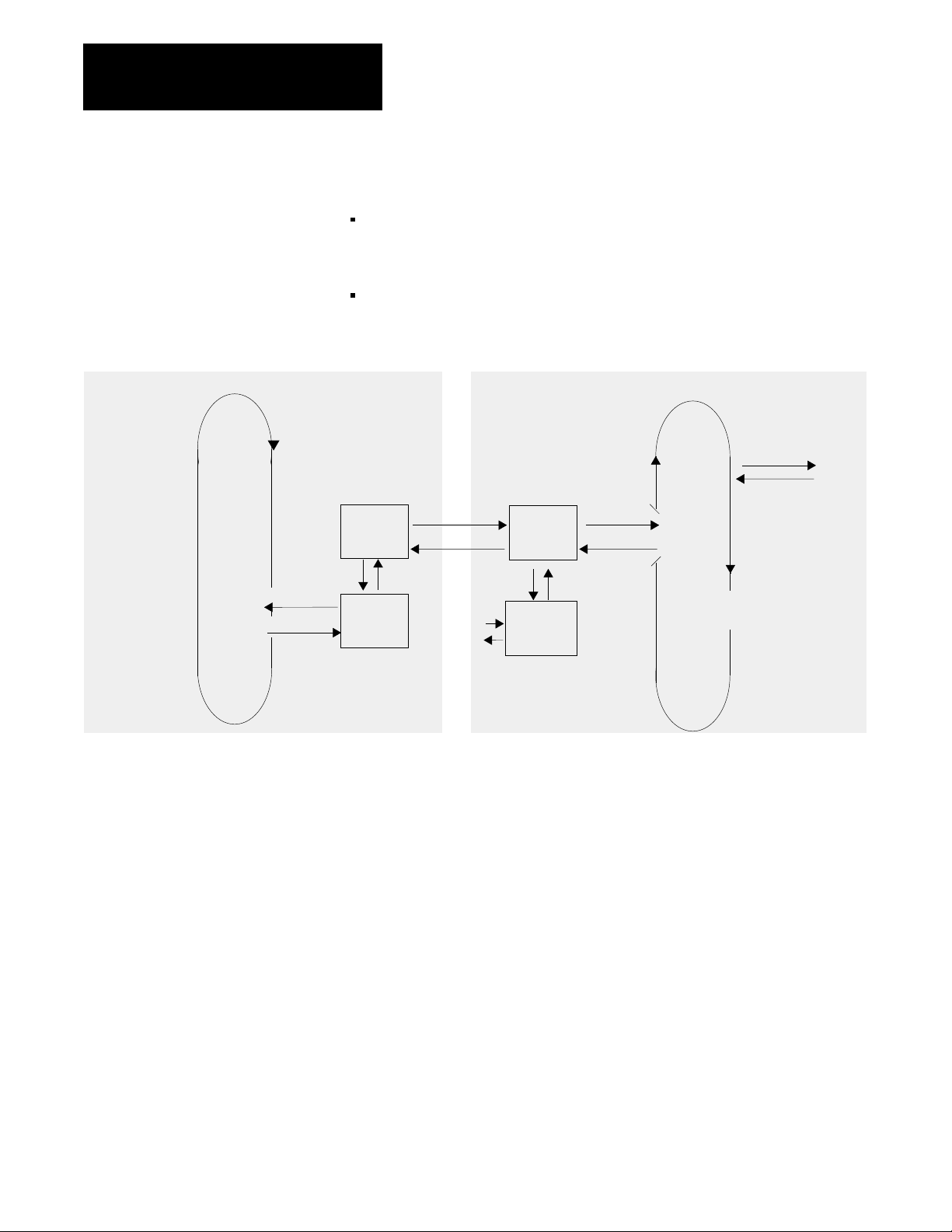
Chapter 8
Transferring Discrete and BlockTransfer Data
During each remote I/O scan:
the supervisory processor transfers 2, 4, 6 or 8 words—depending on
whether the adapter-mode processor is configured as a 1/4, 1/2, 3/4 or
full rack
the adapter-mode processor transfers 2, 4, 6 or 8 words—depending on
whether the adapter-mode processor is configured as a 1/4, 1/2, 3/4 or
full rack
Supervisory Processor in Scanner Mode
Remote I/O
Buffer
Read Inputs
Write Outputs
Remote I/O Scan
I/O Image
Table
Figure 8.1 shows the transfers between supervisory processor output file
and adapter-mode processor input file as well as between adapter-mode
processor output file and supervisory processor input file.
Data Exchange
Data Exchange
x
y
I/O Image
Table
Processor
Resident
Rack
PLC5 Processor in Adapter Mode
Read Inputs
Write Outputs
Data
Exchange
Housekeeping
Immediate I/O
IOT (x)
IIN (y)
Logic
Scan
Program Scan
8-2
Page 98

Chapter 8
Transferring Discrete and BlockTransfer Data
Supervisory Processor
PLC2 0X0-0X7
PLC3 OXX0-OXX7
PLC5 O:X0-O:X7
Supervisory Processor
PLC2 1X0-1X7
PLC3 IXX0-IXX7
PLC5 I:X0-I:X7
Figure 8.1
Automatic
I/O Transfer between Supervisory and
AdapterMode Processors
Supervisory Processor
Word
0
1
2
3
4
5
6
7
Word
0
1
2
3
4
5
6
7
Word 0 is reserved for block transfer and status.
Output File
Supervisory Processor
Input File
AdapterMode Processor
I:30 - I:37 (or adapter image file)
0003040710131417 0003040710131417
Input File
AdapterMode Processor
O:30 - O:37 (or adapter image file)
0003040710131417 0003040710131417
Output File
15298
If data from the supervisory processor is intended to control outputs of the
adapter-mode processor, the ladder logic in the adapter-mode processor
must move the data from its input file (I/O rack 3 or the adapter image file)
to its output file (local I/O). Use XIC and OTE instructions for bit data;
use move and copy instructions for word data.
If you want the supervisory processor to read data from a data file in the
adapter-mode processor, ladder logic in the adapter-mode processor must
move that data to its output file (I/O rack 3 or the adapter image file) for
transfer to the supervisory processor.
8-3
Page 99

Chapter 8
Transferring Discrete and BlockTransfer Data
Programming
Discrete
Transfer in Adapter Mode
For the supervisory processor, use the adapter’s configured I/O rack
number to receive data or store data for transfer.
Using Rack 3 (Addresses 0:300:37 and I:30I:37)
Rack 3 is the default discrete-transfer file for PLC-5/12, -5/15, and -5/25
processors. Typically, each output instruction in one processor should have
a corresponding input instruction in the other processor. The rack number
determines the addresses you use.
The ladder logic in the supervisory processor uses the rack number
(0-76 octal) of the adapter-mode processor.
Condition the ladder logic in the adapter processor with I30/10. When
set, this bit indicates a communication failure between the adapter and
supervisory processors.
Creating an Adapter Image FilePLC5/12, 5/15, and 5/25 Processors
If you use 1/2-slot addressing in a 16-slot chassis, you need rack 3
addresses for scanning processor-resident local I/O on the adapter-mode
processor. In this case, you can create an adapter image file for
transferring data. Before you create an adapter image file, make sure that
these conditions are true:
the PLC-5 processor is in adapter mode
the adapter-mode processor is in a 1771-A4B I/O chassis
you are using 1/2-slot addressing
you have not inhibited rack 3 by setting the rack inhibit bit 3 in
processor status word 27
To create the adapter image file, create a 16-word integer file. This file
must be 16 words regardless of whether you use 4-word or 8-word
transfers. This file must be a unique integer file, for use only as an adapter
image file. Words 0-7 are used for output; words 8-15 are used for input.
Bits are numbered in decimal 0-15 for each word.
To tell the processor which file is the adapter image file, enter the file
number in word 25 of the processor status file. You enter this file number
on the processor status screen. For more information about the processor
status screen, see the chapter on using status data in the programming
software documentation.
Important: If you are using an adapter image file (instead of the rack 3
image), then you cannot use block transfers between the supervisor and the
adapter-mode processor.
8-4
Page 100

Chapter 8
Transferring Discrete and BlockTransfer Data
Condition the ladder logic in the adapter-mode processor with word 8, bit 8
decimal of the adapter image file. When set, this bit indicates a
communication failure between the adapter and supervisory processors.
ATTENTION: Do not program block transfers to a
supervisory processor if you create an adapter image file.
Transferring Bits between Supervisory and AdapterMode Processors
Figure 8.2 shows ladder logic for transferring bit 17 of the supervisory
processor’s output image word 7 and bit 16 of the adapter-mode
processor’s output image word 5. The x represents the adapter-mode
processor’s rack number; rack 3 is the simulated rack for the adapter-mode
processor. This example assumes 1-slot or 2-slot hardware addressing.
Figure 8.2
Transferring
Supervisory Processor (PLC2) Adapter Processor (PLC5)
0x7
Ix5
16
17
Bits Using Rack 3 in the AdapterMode Processor
I:37
17
When the supervisory processor sets its output file bit 0x:7/17, input file bit
I:37/17 in the adapter-mode processor is automatically set. In the same
way, when the adapter-mode processor sets output file bit O:35/16, input
file bit Ix:5/16 in the supervisory processor is automatically set.
Figure 8.3 shows the ladder logic if you created an adapter image file
because you need rack 3 addresses for local I/O. This example uses N51
as the adapter image file.
Figure 8.3
Transferring
Supervisory Processor (PLC2) Adapter Processor (PLC5)
0x7
Bits Using Your Own Adapter Image File
N51:15
O:35
16
16
Ix5
17
15
N51:05
14
8-5
 Loading...