

Page 1
Allen-Bradley
ControlNet
KT Emulation
Dual-port
Interface
Specification
(Cat. No. 1784-DPC1)
Reference
Manual
product icon
Page 2

Important User Information Because of the va riety of uses for the products described in this publi-
cation, those responsible for the application and use of this control
equipment must satisf y themselves that all necessary steps have been
taken to assure that each application and use meets all performance
and safety requirement s, including any applicable laws, regulations,
codes and standards.
The illustrations, charts, sample programs and layout examples
shown in this guide are intended solely for ex am p le. Si nce there are
many variables and requirements associated with any particular
installati on, Alle n-Bradley does not assume responsibility or liability
(to include intellectual property liability) for actual use based upon
the examples shown in this publication.
Allen-Bradley publ ication SGI- 1.1, Safety Guideline s for the Appli ca-
tion, Installation and Maintenance of Solid State Control (available
from your local Allen-Bradle y of fice) describes s ome i mpo rt ant
differences bet ween solid-state equipment and electromechanical
devices which should be taken into consideration when applying
products such as those described in this publication.
Reproduction of the contents of this copyrighted publication, in
whole or in part, without written permission of Allen-Bradley
Company, Inc., is prohibited.
Throughout this manual we use notes to make you aware of safety
consideration s:
A TTENTION: Identifies infor mation about practi ces
or circumstances that can lead to personal injury or
!
Attention helps you to:
• identify a hazard
• avoid the hazard
• recognize the consequences
Important: Identifies information that is critical for successful appli-
cation and understand ing of the pro duct.
ControlNet is a trademark of ControlNet International.
Data Highway Plus, DH+ and PLC-5 are trademarks and PLC-2 and PLC-3 are registered trademarks of Allen-Bradley Company,
Inc.
death, property damage, or economic loss.
Page 3

Preface
Preface
Read this preface to familiarize yourself with the rest of the manual.
This preface covers the following topics:
• why you should use this manual
• who should use this manual
• what reference material and previous exposure you should have
• what you receive with this package
• what terms and conventions you should know before you begin
the first chapter
Why You Should Use This Manual
Reference Material and Previous Exposure
What You Receive with This Package
You should use this manual if you:
• want to build a driver for the 1784-KTCX card that is specific to
your computer operatin g syste m.
You should have the following background and materials:
• ControlNet Network System Overview (Pub. 1786-2.12)
• Contr olNet Cable System Planning and Installation Manual
(Pub. 1786-6.2.1)
• the programming manual for the tar get programmable
controllers.
• the hardware reference ma nua l for the host personal computer or
workstation.
• a comprehensive knowledge of Contr olNet network operations
and functions.
With this package you should receive:
• one Dual-Port Interface Specifications Reference M an u al
(Publication 1784-6.2.4).
• software license
Publication 1784-6.2.4 - September 1997
Page 4

P-2 Preface
What You Receive with This Package
As you read this manual, you need to know that:
This: Refers to this:
KTCX card 1784-KTCX card
BA Base address of the KTCX card as installed.
DP ADDR The dual-port address. I t i s lo cated at 03000h
(3000:0000h) beyond the installed address of
the KT module.
DP ADDR :0800h to :0806h Memory-mapped hardware addresses.
hhex code
host Personal computer or wo rkstation of driver.
XXXXXh XXXX:XXXXh
node The point at which devices interface with the
network.
sending no de (also originating node ) The (originating) nod e sending the com mand
or message.
receiving node The node sending the reply to the command.
local network The netwo rk containi ng the origin ating node.
PCCC Programmable Controller Communication
Commands
LSAP Link Service Access Point
on-link node A node on the local network.
Publication 1784-6.2.4 - September 1997
Page 5

Preface 3
Allen-Bradley Support Allen-Bradley offers support services worldwide, with over 75
Sales/Support Of fices, 512 authorized Distributors and 260
authorized Systems Int egra tors located throughout the United States
alone, plus Allen-Bradley representatives in every major country in
the world.
Local Product Support
Contact your local Allen- Bradley representative for:
• sales and order support
• product technic al training
• warranty support
• support service agreements
Technical Product Assistance
If you need to contact Allen-Bradley for technical assistance, please
review the information in the T rouble shoot ing chapter first . Then call
your local Allen-Brad ley representative.
Your Questions or Comments on this Manual
If you find a problem with this manual, please notify us of it on the
enclosed Publicat ion Problem Report.
If you have any suggestions for how this manual could be made more
useful to you, please contact us at the address below:
Allen-Bradley Company, Inc.
Automation Group
T echnical Communication, Dept. 602V, T122
P.O. Box 2086
Milwaukee, WI 53201-2086
Publication 1784-6.2.4 - September 1997
Page 6

P-4 Preface
Notes:
Publication 1784-6.2.4 - September 1997
Page 7

Table of Contents
Overview of the KTCX Card Environment
What Your Driver Must Do at Start-up
Chapter 1
What This Chapter Covers. . . . . . . . . . . . . . . . . . . . . . . . . . . . . . . . . . . . . . .1-1
ControlNet Network En vi ronment . . . . . . . . . . . . . . . . . . . . . . . . . . . . . . . . .1-1
The ControlNet System Overview . . . . . . . . . . . . . . . . . . . . . . . . . . . . . . .1-1
Node Addressing and Node Table . . . . . . . . . . . . . . . . . . . . . . . . . . . . . . .1-2
Control and Configuration of Programmable Logic Controllers. . . . . . . . . .1-3
Off-link Messaging . . . . . . . . . . . . . . . . . . . . . . . . . . . . . . . . . . . . . . . . . .1-3
Data Flow: Application to Dual-port Interface to Network. . . . . . . . . . . . . . . .1-3
Reserved Sections for Sy stem Memory and M ailboxes . . . . . . . . . . . . . . .1-4
LTCX Card Requirements . . . . . . . . . . . . . . . . . . . . . . . . . . . . . . . . . . . . . . .1-4
Selected Hardware In terrupt and Address. . . . . . . . . . . . . . . . . . . . . . . . .1-4
Selected I/O Address . . . . . . . . . . . . . . . . . . . . . . . . . . . . . . . . . . . . . . . .1-4
Segment:Offset Notation and Base Address . . . . . . . . . . . . . . . . . . . . . . .1-5
Operating States. . . . . . . . . . . . . . . . . . . . . . . . . . . . . . . . . . . . . . . . . . . . . .1-6
KTCX States and Trans iti ons. . . . . . . . . . . . . . . . . . . . . . . . . . . . . . . . . . .1-6
Chapter 2
What This Chapter Covers. . . . . . . . . . . . . . . . . . . . . . . . . . . . . . . . . . . . . . .2-1
Using the KTCX Memory-Mapped Hardware . . . . . . . . . . . . . . . . . . . . . . . . .2-1
Initializing the KTCX Card . . . . . . . . . . . . . . . . . . . . . . . . . . . . . . . . . . . . . . .2-2
Usage With Interrupts . . . . . . . . . . . . . . . . . . . . . . . . . . . . . . . . . . . . . .2-3
KTCX Card Shutdow n . . . . . . . . . . . . . . . . . . . . . . . . . . . . . . . . . . . . . .2-3
Restarting the KTCX Card After Shutdown. . . . . . . . . . . . . . . . . . . . . . .2-3
How Your Driver Operates the KTCX Card
Chapter 3
What This Chapter Covers. . . . . . . . . . . . . . . . . . . . . . . . . . . . . . . . . . . . . . .3-1
General Communication Configurations . . . . . . . . . . . . . . . . . . . . . . . . . . . .3-1
Message Timeouts . . . . . . . . . . . . . . . . . . . . . . . . . . . . . . . . . . . . . . . .3-1
Data Transmission and Reception. . . . . . . . . . . . . . . . . . . . . . . . . . . . .3-1
Typical Communication s Methodology. . . . . . . . . . . . . . . . . . . . . . . . .3-2
Solicited Messaging . . . . . . . . . . . . . . . . . . . . . . . . . . . . . . . . . . . . . . . 3 -2
Unsolicited Messaging . . . . . . . . . . . . . . . . . . . . . . . . . . . . . . . . . . . . .3-2
Multi-Message Queuing . . . . . . . . . . . . . . . . . . . . . . . . . . . . . . . . . . . .3-2
Send and Receive Overview . . . . . . . . . . . . . . . . . . . . . . . . . . . . . . . . . . . . .3-2
Operating the Send and Receive Flags . . . . . . . . . . . . . . . . . . . . . . . . .3-2
General Packet Structure . . . . . . . . . . . . . . . . . . . . . . . . . . . . . . . . . . . . . . .3-3
Send Mailbox . . . . . . . . . . . . . . . . . . . . . . . . . . . . . . . . . . . . . . . . . . . . . . . .3-4
Procedure for Sending Data to the KTCX Send Mai lbox . . . . . . . . . . . . .3-4
Send Packet Examples . . . . . . . . . . . . . . . . . . . . . . . . . . . . . . . . . . . . .3-4
Send Data Memory Map. . . . . . . . . . . . . . . . . . . . . . . . . . . . . . . . . . . .3-6
Receive Mailbox . . . . . . . . . . . . . . . . . . . . . . . . . . . . . . . . . . . . . . . . . . . . . .3-7
Procedure for Receiving Data from the KTCX Receive Box. . . . . . . . . . .3-7
Receive Processes: Polled and Interrupt . . . . . . . . . . . . . . . . . . . . . . . .3-7
Code Examples for Poll ed and Interrupt Messaging. . . . . . . . . . . . . . . .3-8
Publication 1784-6.2.4 - March 1997
Page 8

toc–ii Ta ble of Contents – C ontrolNet KT Emulation Dualport Interface Specification
Receive Examples. . . . . . . . . . . . . . . . . . . . . . . . . . . . . . . . . . . . . . . . .3 -8
Receive Data Memory Map. . . . . . . . . . . . . . . . . . . . . . . . . . . . . . . . . .3-9
Example Code for Polled and Interrupt Messaging
Defined Statements for the KTCX Card
Appendix A
Network Configurations for Polled and Interrupt Messaging. . . . . . . . . . . . . .A-1
Example Code for Polled Messaging . . . . . . . . . . . . . . . . . . . . . . . . . . . . . . .A-2
Example Code for Interrupt Messaging . . . . . . . . . . . . . . . . . . . . . . . . . . . . .A -3
Appendix B
KTCX Card Definitions. . . . . . . . . . . . . . . . . . . . . . . . . . . . . . . . . . . . . . . . . .B-1
Structures that Access the
KT Dual-port. . . . . . . . . . . . . . . . . . . . . . . . . . . . . . . . . . . . . . . . . . . . . . . . .B-2
Publication 1784-6.2.4 - March 1997
Page 9

Chapter
1
Overview of the KTCX Card Environment
What This Chapter Covers T o build a driver that handles all the conditions of your system, you
must be familiar with:
• ControlNet Networ k Enviro nment
• Hardware and Software Interface of the KTCX Card
• Data Flow From Application to KTCX Dual-port Interface to
Network
• KTCX Card Requirements and Operating S tat es
ControlNet Network Environment
Read the following sections be fo re building your driver:
• The ControlNet System Overv iew
• Node Addressing and Node Table
• Control and Configuration of Programmable Controllers
• Off-l ink Messaging
The ControlNet System Overview
ControlNet networks allow you to combine the benefits of several
networks into one. I/O, PLC interloc king, peer-to- pe er messaging,
and programming can all be handled on the same link. The
ControlNet network's 99 nodes, redundant media, high throughput
and determinism, allow your netwo rk to handle large distributive
processes, large amounts of remote and analog data, and high-spe ed
discrete remote and analog data.
The KTCX card connects the host to a ControlNet network environment. The KTCX card's KT Emulation allows unscheduled messaging and programming to be handled on the ControlNet network.
Unscheduled messa ges are performed during the unsc heduled time in
the network update interval and are non-deterministic. The traffic
load of your scheduled messaging determines how much time is
available for unsche duled messaging. More information on unscheduled messages can be found in the ControlNet Network System Over-
view (1786-2.9).
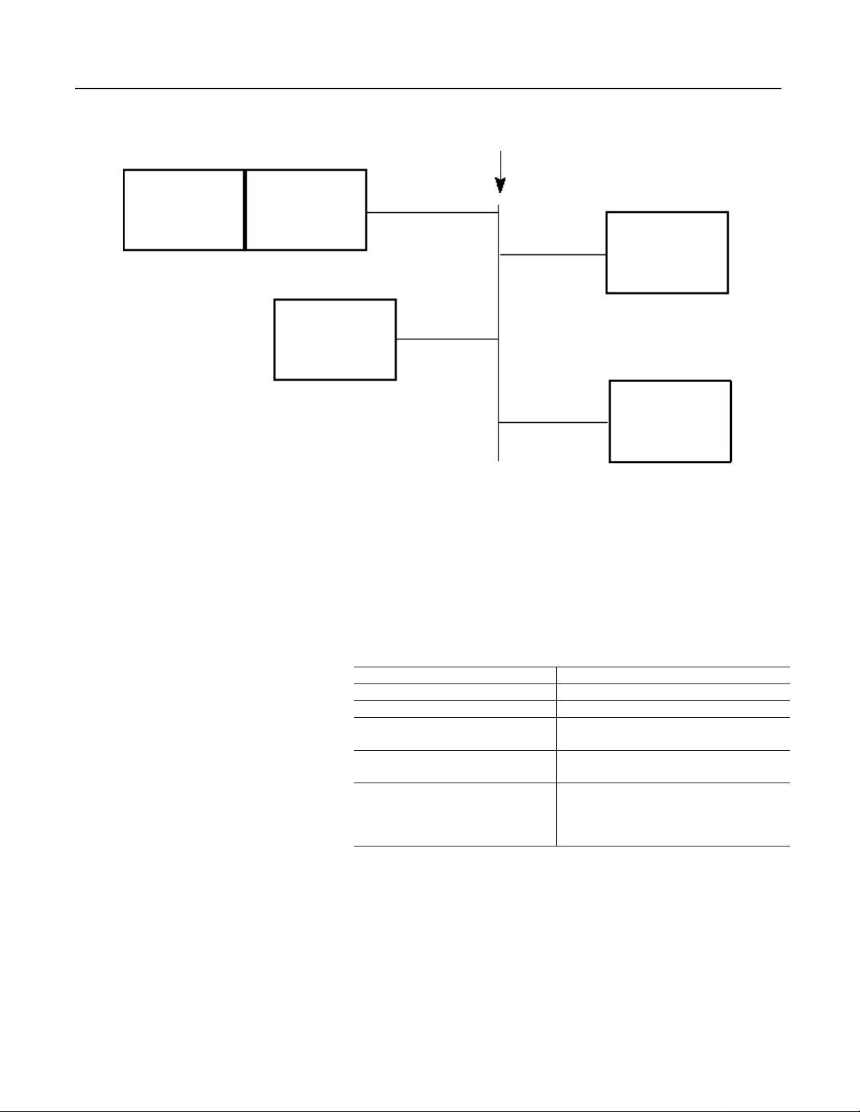
Figure 1.1 outlines the configuration of a t ypical ControlNet network
environment.
Publication 1784-6.2.4 - September 1997
Page 10
1-2 Over view of the K TCX Car d Envi ronm ent
Figure 1.1 ControlNet Network Overview
ControlNet Network
Host PC with
ISA/EISA Bus Interface
ControlNet Taps: 1786-TPR
KTCX Ca rd
1771 ACN
I/O Adapters
1786-TPYR
1786-TPS
1786-TPYS
ControlNet Tap
ControlNet Tap
ControlNet Tap
ControlNet Tap
1794 ACN
Flex I/O Adapters
PLC-5C Processors
Node Addressing and Node Table
The KTCX does not maintain an active node table. However, to
accommodate existing applications the KTCX emulates an active
node table. All nodes will appear to be act ive when the KTCX is
online whether they a re active or not. Thi s is to allow ol d applic ations
to communicate with the KTCX card. The operatin g states described
in the emulated node table are defined as follows:
Puiblication 1784-6.2.4 - September 1997
Card Network State Node Table Entry Status
Reset 0xFF’s
Off-line 0xFF’s
Lonely The node’s entry is it s address. Ever ything else
reads 0xFF.
Listen-only The node’s entry is its address. Everything else
reads 0xFF.
On-line All entries are initialized to the next node
address. For example, 0x02 points to node
0x03. Node 0x03 points to node 0x04. Node
0x04 points to node 0x05 and so on.
Page 11
Overview of the KTCX C ard Environment 1-3
Control and Configuration of Programmable Logic Controllers
To configure a programmable controller, you must refer to the applicable processor manua l that came with the programmable controller.
This processor manual, along with the controller’s programming
manual, shows you how to control and program your devic e.
Off-link Messaging
The KTCX does not support off-link connections within the
ControlNet network envi ronment.
Data Flow: Application to
Dual-port Interface to
Network
Data Flow
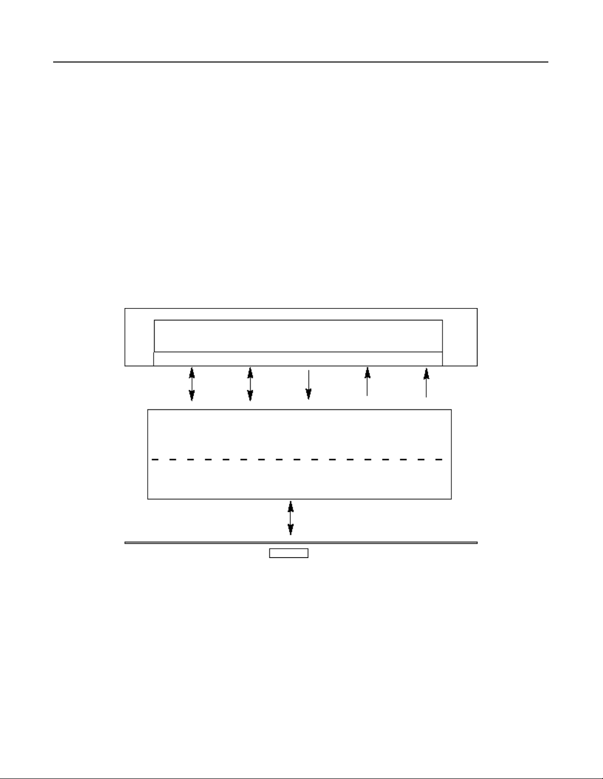
To control and monitor devices properly, the host application
program(s) must communicate correctly with the other node(s) on the
network. Data flows to and from the host application as shown in the
directional pathwa ys in Figure 1.2.
Figure 1.2
Data Flow through KTCX Card Dual-port Interface
Host Application
Driver
Flags Status Send Mailbox Receive Mailbox Node Table
Dual-port
PC/Workstation
KTCX Card
Data Flow
ControlNet
Network
Publication 1784-6.2.4 - September 1997
Page 12

1-4 Over view of the K TCX Car d Envi ronm ent
Reserved Sections for System Memory and Mailboxes
The KTCX card reserves sections of the dual-port’s 2K memory to
use as “mailboxes.” These mailboxes hold an d transf er packets of
data, commands, and status inf or mation for both the KTCX card and
the application running on the host.
Important: You cannot mix 8-bit and 16-bit cards within a 64K
segment boundary. That is, a Series A card cannot be placed in the
same segment range of D000:000 - DFFF:0000 or C000:0000 CFFF:0000. The eight bit card may not work. Two cards (one 8-bit
and one 16-bit) can be placed with one in the C000:0000 CFFF:0000 range and one in the D000:0000 - DFFF:0000 range.
KTCX Card Requirements This section describe s the requirements and operating state s of the
KTCX card:
• the KTCX card's selected hardwa re interrupt and address
• the KTCX card's selected I/ O addre ss
• the “segment:offset” notation as it appli es to the base address
• the KTCX's initial state memory configuration
• the KTCX's operating sta tes
Selected Hardware Interrupt
The KTCX card can generate a hardware interrupt to the host PC or
workstation to sig nal that it has received a packet of data. The card is
set to be polled by defa u lt. Th e K TCX card must be configured
through the application to generate an interrupt. Refer to the
1784-KTCX Installation Manual (Pub. 1784-5.20) for more information about available ad dresse s. Interrupts support ed by the KTCX
card are 3, 4, 5, 7, 10, 11, 12, and 15.
Selected I/O Address
The 1784-KTCX Installation Manual (Pub. 1784-5.20) describes the
establishment of the I/O address. Make sure the current setting does
not conflict with an othe r card on the host. If interrupts are used, refer
to the example code in Appendix A.
Puiblication 1784-6.2.4 - September 1997
Page 13

Overview of the KTCX C ard Environment 1-5
Selected Base Address
The KTCX dual-port is 16K in size. See the 1784-KTCX Installation
Manual (Pub. 1784-5.20) for a ll the available dual-port and I/O
addresses and their respe ctive settings. The KT Emulation dual-port
location is the same as the 1784-KT. For example: if the dual-port
address is at 0D000h, then the KT Emulation dual -port address starts
at 0D300h.
Segment:Offset Notation and Base Address
The KTCX card’s dual-port emulation interface is 2048 bytes RAM
and 7 bytes that mimic the KT’s 7 bytes of memory-mapped hardware. The dua l-port RAM contains all the host-accessible memory,
registers, and flags.
The address of this dual-por t RAM is 300h:0 in beyond the host base
address at which you install the KTCX card. Refer to Table 1.A for
examples of how to calculate a dual-port address from the base
address. You will find the complete list of possible installation
addresses for KT modules in the 1784-KTCX Installation Manual
(Pub.1784-5.20).
Table 1.A“Segment:Offset” Notation for Dual-port Addresses
If you install the
KTCX card at:
C000:0000h C300:0000h C300:0000h to C300:0806h
D400:0000h D700:0000h D700:0000h to D700:0806h
The dual-port RAM
starts at:
The valid range of dual-port
addresses is:
Important: Since a c hange in the segment a ddress doe s not aff ect the
offset addresses, we refer only to the offset addresses throughout this
document.
Publication 1784-6.2.4 - September 1997
Page 14

1-6 Over view of the K TCX Car d Envi ronm ent
Operating States The KTCX card has five operating states: r eset, off-line, lonely,
listen-only and on-line.
Reset
The card is on the network and waiting for start-up procedure to be
placed on-line.
Off-Line
The initial state of the KTCX card at start-up must be off-line. In the
off-line mode, the KTCX card is not on the ControlNet network a nd
can neither send nor receive messages nor build the node table.
T o properly close the host applica tion and shut down the host, you
must take the KTCX car d off l ine . For a det ailed explanati on, see the
section in Chapter 2 “Taking the KTCX Card Off-Line.”
Lonely
This node is the only active node on the network.
Listen-Only
The node is on the networ k and l istening for network parameters from
the keeper node to bring it on-lin e.
On-Line
The KTCX card is on the network, available to other nodes and able
to send and receive messages. The host appl ication must select the
KTCX card and specify the node address to place it on-line.
The KT alive flag's value transi tions depend on the state of the card.
The states and transiti ons are defined by the following table:
KTCX States and Transitions
State Description
0 KT emulation has not been initiated or the card is off-line.
Writing to the flag will not change the value.
4 Communications are being initiated. The card has detected the
star t-up s tring and will now transition to state 3.
3 The card has gone into listen-only mode and is now waiting for
the keeper node to bring it on-line. This byte will continue to
rewrite itself ever y 10ms.
2 The card is now on-lin e and is ready for PCCC (Prog rammable
Controller Communication Commands) messaging. This byte
will continue to rewrite itself every 10ms.
Puiblication 1784-6.2.4 - September 1997
Page 15
Overview of the KTCX C ard Environment 1-7
Transition Description
A The initialization code (C3,...,0) has been placed in the dual-port and
offset 802h is set to 1.
B KT emulation is placing the card in listen-only mode. The card is now
waiting for the keeper to bring it on-line.
C The KT_alive flag is continually being written with a 3 every 10 ms.
D The card is transitioning to the on-line state and the KT_alive flag is
being set to 2.
E The KT_ alive flag is continually being written with a 2 every 10 ms.
F The card has gone into listen-only due to a network reset command.
G The card has detected a new initialization string and is going back to
its initialization state.
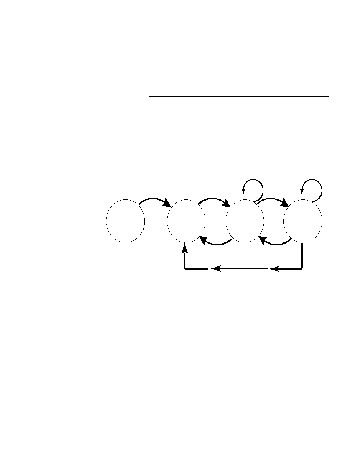
If the alive flag does not change value, then the KTCX card has been
taken off -line or the card has not been initialize d. Figure 1.3 provide s
a state diagram for a further descript ion of the states and transitions.
Figure 1.3
Explanation of KTCX Alive States and Transitions
AB
0 234
Important: The card will transition from the listen-only or on-line
states to the lonely state wheneve r the node becomes the only active
node on the network. The card will also trans ition to listen-only or
on-line when it is in the lonely state if it is joined by another active
node on the network.
C
G
G
D
F
E
Publication 1784-6.2.4 - September 1997
Page 16

1-8 Over view of the K TCX Car d Envi ronm ent
Notes:
Puiblication 1784-6.2.4 - September 1997
Page 17

Chapter
2
What Your Driver Must Do at Start-up
What This Chapter Covers This chapter explains the start-up requirements of the KTCX card.
Your driver must:
• Use the KTCX Memory-Mapped Hardware
• Initializ e the KTCX Card
Using the KTCX Memory-Mapped Hardware
Before you begin building your dri ver, you must be familiar with the
KTCX card's memory-mapped hardware. There are sev en memorymapped addresses, but byte :0800h is r eserved. The KTCX maps the
dual-port just like the 1784-KT. However, some funct ions such as
diagnostics are not required. These unnecessary functions are designated by “N/A”, not applicable. The following sections describe
memory-mapped hardware bytes :0801h through :0806h.
Table 2.A Initial State Memory Map of du a l-port
Byte Description
:0000h KTCX KT
Emulation Mode
:0001h KTCX KT
Emulation Mode
:0002h KTCX KT
Emulation Mode
:0003h KTCX KT
Emulation Mode
:0004h KTCX Link State INI FFh = off-line
:0005h Link Address INI (node address) R W N/A
:0006h Link Protocol INI N/A N/A N/A
:0007h Link Baud Rate INI N/A N/A N/A
:0008h Link Termination
Resistor
:0009h Reserved --- --- --- All reserved bytes must be set to 00h.
:000Ah Reserved --- --- --:000Bh Reserved --- --- --:000Ch Reserved --- --- --:000Dh Reserve d --- --- --:000Eh Reserved --- --- --:000Fh Reset Diagnostic
Counters
:0010h Reserved --- --- --- All reserved bytes must be set to 00h.
Function
INI C3h R W Your application must set th e se byt es to in iti ali ze the
INI 00h R W
INI 00h R W
INI 00h R W
INI N/A N/A N/A
CMD N/A N/A N/A
1
Contents = Meaning
00h = on-line
Typical Access
KTCX Host
R . W N/A
2
Comments
KTCX card.
Publication 1784-6.2.4 - September 1997
Page 18

2-2 What Your Driver Must Do at Start-up
:0011h Reserved --- --- --:0012h KTCX_alive STAT 02h = KTCX is
functioning
:0013h KTCX_dupe_node STAT 00h = KTCX address
Valid
01h = KTCX duplicate
found
:0014h KTCX_off_KTCX CMD 01h = shutdown
KTCX
Note: First write 00h
to byte :0015h.
:0015h KTCX_stopped_flag STAT FFh = KTCX stopped W R/W This byte is responsible for shutting the KTCX card
:0016h KTCX Module State INI N/A N/A N/A
➀ CMD = Command From Host to KTCX; DIAG = Diagnostic Counter; STAT=Status; INI = Initialization; N/A = Not Applicable
➁ R = Read; W = Write
W R/W See KTCX Alive section in chapter one.
W R A value other than 00h means the installed KTCX
address is the same as another station on the link.
R W Host command to KTCX to shut K TCX down. The
KTCX scans for 01h every 10 msec. However, if an
interrupt is used, then shutdo wn is preforme d
immediately.
down.
Initializing the KTCX Card To bring the KTCX card in KT Emulation mode and communicat ing
on the network, follow these steps (See Appendix B for the defines):
1. Reset the hardware by performing the following sequence:
outportb( H186RESET, 0 );// hold the card in reset
outportb( H186RUN, 0 ); // start the card
2. Wait 4 seconds for the operating state to change to start-up.
3. Load the following sequence into the dual-port:
Offset Value (Range) Comments
0000h 0xC3
0001h 0x00
0002h 0x00
0003h 0x00
0004h 0x00 on-line
0005h 1-99 node address
0014h 0x00 free from shutdown
4. Release the card by writing a 1 to byte offset 0802h.
5. Monitor the offse t 0012h (KTCX_alive flag until it transitions
from state 4 to state 2 at which time the card is online. This
process takes a bout 5 s econds .) I f the ke eper node is non-ex istent,
the KTCX_alive flag will stay in state 3 until a keeper node is in
the network. Once the card is online (KT alive flag = 2), PCCC
messages may be transmitted.
Publication 1784-6.2.4 - September 1997
Page 19

What Your Driver Must Do at Start-up 2-3
Usage With Interrupts
The KTCX, by default, is set up to be poll operated even if the card
has been set up to interrupt the host. Bit s 0 and 1 at byte off set 801h
must be set to configure the card for interrupts. Table 2.B show you
how to set bits 0 and 1 to in order to conf igure your card to m eet your
specifications.
Table 2.B Bit Values for Configuring the dual-port
Value=0 Value=1
Bit 0 do not interrupt when send
box is available
Bit 1 do not interrupt when data is
available in receive box
interrupt when send box is
available
interrupt when data is available in receive box
KTCX Card Shutdown
Use the following instructions to shutdown the KTCX car d. ( Refer to
example code for details):
1. Write an FFh into byte offset 0004h (KTCX link state)
2. Write an 01h into byte offset 0014h (KTCX_off_KTCX)
3. Wa it until byte offset 0015h (KTCX_stopped_flag) transitions to
an FFh. This should complete in 0.5 seconds. If not, there is a
critical error.
4. Write a 01h into byte offset 803h.
5. Write a 04h into byte offset 0012h.
6. Write a 00h into byte offset 014h.
Restarting the KTCX Card After Shutdown
After card shutdown, the emulation can be restarted without hard
resetting the card by retur ning to ste p 2 in “Initializing the KTCX
Card”
Publication 1784-6.2.4 - September 1997
Page 20

2-4 What Your Driver Must Do at Start-up
Notes:
Publication 1784-6.2.4 - September 1997
Page 21

Chapter
How Your Driver Operates the KTCX Card
What This Chapter Covers To make sure that each pa cket of information gets to its proper
destination wit hout error, your driver needs to know how to correctly
operate the KTCX card. So that you have the pertinent information
necessary to operate the KTCX card, this chapter describes the
following:
• General Communications Configurations
• Send and Receive Overview
• General Packet Structure
• Send Mailbox
• Receive Mailbox
• Acknowledgment Confirmation Area
3
General Communication Configurations
From the originating station you can communicate to any station,
such as 1770-KFCs, PLC5s, or KTCX Cards with applications that
support PCCC messaging in a ControlNet network.
Message Timeouts
The 1784-KT card did not allow for timeouts on a per message basis
but due to the nature of ControlNet, ti meout conditions can vary
depending on th e network parameter s. To accommodate this function,
the word at offset 084h is used to set this tim eout in seconds. If the
value is 0 then the timeout value is set to 120 seconds by default. Any
other value will set the timeout to that specific value. The timeout
value can range from 1 to 320 seconds. If no other node exists on the
network, the message timeout value will be substantially less.
Data Transmission and Reception
The KTCX can have a total of 15 outstanding messages. See the
example code in Appendix A for details.
Important: The KTCX uses a 186EC 20 MHz or (series A) or 25
MHz (series B) so the timings between operations will be different
when compared to the KT family of products.
Publication 1784-6.2.4 - September 1997
Page 22

3-2 How Your Driver Operates the KTCX Card
Typical Communications Methodology
To send data you must:
• Build the data packet.
• Send the data packet.
• If expecting a reply, follow the receive data methodology when
T o receive data you must:
• Receive an interrupt from the KTCX card if using interrupts, or
• Copy the packet from the Receive Mailbox.
• Return the application to the mainstream.
Solicited Messaging
In the case of solicite d messaging where the card behaves as a client,
all messages are transmitted to the destination.
the reply arrives.
monitor receive mailboxe s if not.
Send and Receive Overview
Unsolicited Messaging
The card supports unsolic ited messaging from devices like the
PLC5-C and KFC o p era tor i nter fac es .
Multi-Message Queuing
The application that keeps tr ack of the transaction numbers (TNS)
must handle multi-messa ge queuing. It must ass ociate the ord er of incoming and out-going message packets. The receiving node always
returns the TNS unchanged. Always keep the same TNS when
responding to a remote request, otherwise the remote sender will not
recognize the packet is associated with the original request .
Use the following procedure s to send and receive messages and
commands.
Operating the Send and Receive Flags
Two flags—Access Request and Data Valid—control each send and
receive mailbox. When sendi ng commands or mess ages, use the Send
Access Request flag (byte 0080h) and the Send Data Valid flag (byte
0081h). When receiving commands or message s, use the Receive
Access Request flag (byte 0480h) and the Receive Data Valid flag
(byte 0481h).
Publication 1784-6.2.4 - September 1997
The host and the KTCX card transfer control of these bytes during
each transmission. When both these bytes are set to 00h, the KT card
has control of the mailbox. When both of these bytes are set to 01h,
then the host has control of the mailbox.
Page 23

How Your Driver Operates the KTCX Card 3-3
Important: The mailbox is in an invalid state if both the Access
Request and the Data Valid bytes show opposing values (one shows
00h and the other 01h).
Reading and Writing Access Reques t and Data Valid Flags.
The order in which you read these flags must be as follows.
T o read access request and data valid flags:
1. Read the Access Request byte (0080h for sending or 0480h for
receiving).
2. Read the Data Valid byte (0081h for sending or 0481h for
receiving).
The order in which you write these flags must be as follows.
To write access request a nd data valid flags:
1. Write the Data Valid byte (0081h for sending or 0481h for
receiving).
2. Write the Access Request byte (0080h for sending or 0480h for
receiving).
General Packet Structure The general form of PCCC message packets is a combination of
protocol command, and data bytes:
• Protocol bytes make sure that the packet gets to its destination,
handling routing, error checking, and error recovery. The
protocol bytes are the set of inst ructi ons and data that th e prot ocol
layer returns. This layer is emulated by the KTCX card.
• PLC commands and transaction identification control the PLC
and provide a serialized mea ns of tracking packets.
• Data bytes contain the information from the application or PLC.
For more information on the contents of the PCCC message packet,
refer to the DF1 Protocol and Command Set (Pub. 1770-6.5. 16).
Refer to table 3.A to see the structure of a typical packet .
Tab le 3.A Typical Packet Structure
Protocol Bytes
Command and ID Bytes
Packet Data By tes
PLC Commands
Transaction ID
Application Data
Publication 1784-6.2.4 - September 1997
Page 24

3-4 How Your Driver Operates the KTCX Card
Send Mailbox The dual-port’s send mailbox (bytes: 0082h - :047Fh) can hold up to
1021 bytes. However, you must refer to the DF1 Protocol and
Command Set (Pub. 1770-6.5.16) for the exact size requirements of
packets for each message type. As you develop your driver, you
should refer to the following items in this section:
• Procedure for Sending Data to the KTCX Send Box
• Send Data Packets Examples
• Send Data Me mo ry Map
Procedure for Sending Data to the KTCX Send Mailbox
A TTENTION: Failure to execute the fol lowing steps
can cause your card to behave improperly and cause
!
T o send a packet to the Send Box in the KTCX:
1. Verify that the ACCESS byte is 01h.
damage to your system.
2. Verify that the VALID byte is 01h.
3. Trans fer the message or command packet into the send mailbox.
4. Send the packet by writing 00h to VALID.
5. Write 00h to ACCESS flag.
Now the card is aware of the message packet.
Send Packet Examples
Refer to the following examples as you develop the se nd packet portion of your driver.
Send Packet Procedure #1: Diagnostic Status.
The following steps describe a typical procedure for sending a packet
requesting diagnostic status.
1. The host application buil ds a Diagnostic Status command packet
in a buffer.
2. The host polls the Send Access Request byte (0080h)
3. Host polls the Send Data Valid byte (0081h). If the values of
0080h and 0081h are 01h then the host proceeds.
Publication 1784-6.2.4 - September 1997
4. The host places the Diagnosti c Status packet into the mailbox
beginning at location :0082h.
5. The host zeros the Send Data Valid and Send Access Request
bytes.
Page 25

How Your Driver Operates the KTCX Card 3-5
6. The KTCX card ta kes t he pa cket and sets the S end Data Valid and
Send Access Request bytes to 01h.
7. The KTCX card transmits the packet.
8. The KTCX card receives the response packet.
9. The KTCX card checks the receive mailbox.
10. The KTCX card places the response into the receive mailbox and
then resets the Receive Access Request and Receive Data Valid
bytes to 01h. The host has access to the receive mailbox.
11. The host checks the Receive Access Request and Receive Data
Valid b yte s. If both are 01h, then it copies the Diagnostic Status
Reply packet from the KTCX’s dual-port into its own buffer.
12. The host resets the Receive Data Valid and Receive Access
Request bytes to 00h to allow the KTCX to use the mailbox for
the next packet.
13. The host applicati on acts upon the contents of the Diagnostic Status Reply in the buffer as needed.
Send Packet Example #2: Memory Map of Diagnostic Status
Command.
T abl e 3.B shows what addresses 0082h through 047Fh would contain
during a typical on-link ( local) Diagnostic Status Command. The
transaction number (TNS) to node 5 is 0605h, and the Diagnostic
Status command is 06, function 03.
Table 3.D Memory Map of a Diagnostic Command
Byte Description Contents = Meaning
:0082h Length N/A
:0083h Length N/A
:0084h Reserved N/A
:0085h Reserved N/A
:0086h Destination N/A
:0087h Control N/A
:0088h Packet Type N/A
:0089h Link Service
Access Point
:008Ah CMD (PCCC) N/A
:008Bh Message Status N/A
:008Ch TNS (low byte) N/A
:008Dh TNS (high byte) N/A
:008Eh FUNCTION N/A
:008Fh
:047Fh
DATA N/A
N/A
Publication 1784-6.2.4 - September 1997
Page 26

3-6 How Your Driver Operates the KTCX Card
Send Data Memory Map
Refer to Table 3.C to determine the u se of each dual -po rt addr es s as
you send packets.
Table 3.E Send Data Memory Map
Byte Description
:0080h Send Access
Request
Function
STAT 00h = KTCX control
1
Contents = Meaning
01h = host control
:0081h Send Data Valid STAT 00h = KTCX control
Typical Access
KTCX . . . . . Host
R/W . . . .R/W This is one of the send mailbox control bytes. The proper
R/W . . . R/W This is one of the send mailbox control bytes. The proper
01h = host control
:0082h Length (lo byte) PKTCX --- R . . . . . . . .W Indicates length of the mailbox data in two bytes.
:0083h Length (hi byte) PKTCX --- R . . . . . . . W
:0084h Reserved --- --- --- All reserved bytes must be set to 00h.
:0085h Reserved --- --- ---
:0086h Destination PKTCX --- R . . . . . .. . W Destination ad dress of packe t.
:0087h Control PKTCX 05h R . . . . . . . W Always 05h.
:0088h Packet Type PKTCX 00h R . . . . . . . W Packet type is always 00h.
:0089h Link Service
PKTCX 00h = on-lin k packet R . . . . . . . W Off-link packets need 11 extra bytes which we insert starting
Access Point
:008Ah CMD (PCCC) PKTCX --- R . . . . . . . .W Sent to the destination to effect a command or command
:008Bh Message Status PKTCX --- R . . . . . . . .W Indicates status of message transmission. Command and
:008Ch TNS (low byte) PKTCX --- R . . . . . . . .W The transaction numbers are a 16-bit, 2-byte sequential
:008Dh TNS (high byte) PKTCX --- R . . . . . . .. W
:008Fh
DATA PKTCX --- R . . . . . . . .W Bytes 008Fh-047Fh contain the data to be transmitted (and
:047Fh
2
Comments
order for setting them is 0081h (Send Data Valid) first, then
0080h.
order for setting them is 0081h first, then 0080h (Send
Access Request).
at byte 008Ah. The remaining bytes (008Ah-047Fh) are
shifted 11 places higher. Link Service Access Point (LSAP)
specifies the type of packet and offset.
sequence. Used in comb ination with :008Eh. Refer to
Protocol and Command Set (Pub. 1770-6.5.16)
.
reply messages may contain one of the status codes listed in
the
DF1 Protocol and Command Set (Pub. 1770-6.5.16)
tracking numbers. They make sure that commands and their
replies remain associated. If the host issues a command,
then it must generate and track the TNS. Otherwise, the
issuing PLC or another KTCX card generates the TNS.
the response packet, if any).
DF1
.
1 CMD = Command From Host to KTCX; DIAG = Diagnostic Counter; STAT=Status; INI = Initialization; N/A = Not Applicable
2
R = Read; W = Write
Publication 1784-6.2.4 - September 1997
Page 27

How Your Driver Operates the KTCX Card 3-7
Receive Mailbox To receive packe ts, your driver must check to see that the Receive
Access Request byte (0480h) and the Receive Data Valid byte
(0481h) indicate tha t the mail box is available to it (shown by 01h in
both bytes). Then your driver must copy the packet from the dua lport’s receive mailbox (b ytes 0482h - 07EFh). This mailbox can hold
up to 877 bytes. After copying the packet into its own buffer area,
your driver must sign al the KTCX that it i s done b y zeroin g va lid the n
access bytes.
As you develop your driver, you should be familiar with:
• Procedure for Receiving Data from the KTCX Receive Box
• Receive Processes: Polled and Interrupt
• Receive Packet Examples
• Code Examples for Polled and Interrupt
• Receive Dat a Me mo ry Map
T o read a message in the Receive Box of the KTCX:
Procedure for Receiving Data from the KTCX Receive Box
A TTENTION: Failure to execute the following ste ps
can cause your card to behave improperly and cause
!
1. Verify that the ACCESS byte is 01h.
2. Verify that the VALID byte is 01h.
3. Read the receive box's message.
4. Write a 00h to VALID to send the packet to the receiv e box.
5. Write a 00h to ACCESS flag.
Now the receive box will return the message packet.
damage to your system.
Receive Processes: Polled and Interrupt
You may receive messages via two processes: polled or interrupt.
Process Definition
polled In this mode, the h ost m us t mon it or the R ece iv e A cc ess Requ est an d t he Receiv e
Data Valid bytes to dete rmine when a packet is available for processing.
interrupt The KTCX can send a n int err upt to th e h ost a fte r placi ng a packet in to th e re ceiv e
mailbox. Receive interrupts cannot be disabled in software.
Publication 1784-6.2.4 - September 1997
Page 28

3-8 How Your Driver Operates the KTCX Card
Polled
In the standard KTCX pollin g procedure the c ard can transmi t around
50 messages per second. To have a faster t ransmissi on ra te, the hos t t o
KTCX interrupt word located at offset 3FFCh should be written to
after the send flags have been set. This should be done on a per
message basis.
Interrupt
The KTCX interrupt word is at offse t 3FFCh in the dual -port. When
the host is interrupted, offset 3FFCh (assuming the dual- port address
is 0D000h) must be read in order for the interrupt to be cleared. This
offset is the second to last word in the dual-port. Refer to Appendix A
for example code for setting the card to int errupt.
Interrupts for Multi-Tasking Operations
You may p refe r the i nter ru pt m et hod in multi-tasking operations to
avoid the overhead involved in polling each card. In multi-tasking
systems that ha ve a priori ty a rbitrat or , th e prim ary tas k can be th e poll
routine or the int errupt manage r. Once the KTCX places data into the
receive mailbox, it waits until the host removes it before proceeding.
Important: The 1784-KTCX card cannot shar e int errupts.
Code Examples for Polled and Interrupt Messaging
See Appendix A for example code for both the polled and inter rupt
messaging processes.
Receive Examples
Refer to the following examples as you develop the receive packet
portion of your driver.
Receive Packet Example #1: Memory Map of Message.
T able 3.D shows what addresses:0 482h through:07EFh would
contain during a typical message.
Table 3.F Receive Messag e Example Memory Map
Byte Description Contents = Meaning
:0482h Length 0Bh (low byte)
:0483h Length 00h (high byte)
:0484h SRC (address of packet)
:0485h LSAP(type
designation)
:0486h CMD (PCCC CMD, if any)
:0487h STS (error status of received packet
:0488h TNS (low byte)
:0489h TNS (high byte)
:048Ah:0
7EFh
DATA Data from sender, if any
00h = on-link packet
off-link N/A
Publication 1784-6.2.4 - September 1997
Page 29

How Your Driver Operates the KTCX Card 3-9
Receive Packet Example #2: Interrupt Method.
The following steps describe a typical procedure for receiving a
packet with an interrupt.
1. The KTCX card sets the hardware interrupt.
2. The host removes the packet from the receive mailbox.
3. The host writes 00h to byte 0481h to clea r the Receive Data Valid
flag.
4. The host writes 00h to byte 0480h to clear the Receive Access
Request flag .
Receive Packet Example #3: Polled Method.
The following steps describe a typical procedure for receiving a
packet with the polled method.
1. The host monitors Receive Access Reque st and Receive Data
Valid flags. When both go to 01h data is available.
2. The host removes the packet from the receive mailbox.
3. The host writes 00h to byte 0481h to clea r the Receive Data Valid
flag.
4. The host writes 00h to byte 0480h to clear the Receive Access
Request flag .
Receive Data Memory Map
Refer to Table 3.E to determine the use of each dual-port address as
you receive packets.
Table 3.G Receive Data Memory Map
Byte Description
:0480h Receive A ccess
Request
:0481h Receive Data Valid STAT 00h= KTCX control
:0482h Length (lo byte) PKTCX --- R . . . . . . . .W Indicates length of the mailbox data in two bytes.
:0483h Length (hi byte) PKTCX --- R . . . . .. . . W
:0484h SRC PKTCX --- R . . . . . . . W This is the originating source of the message packet.
Function
STAT 00h= KTCX control
1
Contents = Meaning
01h= host control
01h = host control
Typical Access
KTCX . . . . . Host
R/W . . . R/W This is one of the receive mailbox control bytes. Set 0481h
R/W . . . . R/W This is one of the receive mailbox control bytes. The proper
2
(Receive Data Valid) first, then set 0480h (Receive Access
Request).
order for setting them is :0481h first, then :0480h (Receive
Access Request).
Comments
Publication 1784-6.2.4 - September 1997
Page 30

3-10 How Your Driver Operates the KTCX Card
:0485h Link Service
Access Point
PKTCX 00h= on-link packet R . . . . . . . W Off-link packets need 11 extra bytes which we start at byte
:0468h. The remaining bytes (:0486h-:07EFh) are shifted 11
places higher. LSAP specifies the type of packet and offset.
:0486h CMD (PCCC) PKTCX --- R . . . . . . . . W PCCC command code sent with bit 6 set to 01h. Refer to the
DF1 Protocol and Command Set (Pub. 1770-6.5.16).
:0487h Me ssage Status PKTCX --- R . . . . .. . . W Indicates status of message transmission. Command mes-
sages always contain 00h. Reply messages may contain one
of the status codes listed in the DF1 Protocol and Command
Set (Pub. 1770-6.5.16).
:0488h TNS (low byte) PKTCX --- R . . . . . . . W The transaction numbers are 16-bit, 2-byte sequential track-
ing numbers. They make sure that commands and their
associated replies remain associated. If the host issues a
command, then it must generate and track the TNS.
:0489h TNS (high byte) PKTCX --- R . . . . . . . W Otherwise, the issuing PLC generates the TNS.
:048Ah
:07EFh
➀ CMD = Command From Host to KTCX; DIAG = Diagnostic Counter; STAT=Status; INI = Initialization; N/A = Not Applicable
➁ R = Read; W = Write
DATA PKTCX --- R . . . . . . . W Bytes :048Ah-:07EFh contain the data to be transmitted (and
the response to packet, if any).
Publication 1784-6.2.4 - September 1997
Page 31

Appendix
A
Example Code for Polled and Interrupt Messaging
Important: All en-Bradley assumes no liability for the use of the
example code in this document. It is provi ded strictly as a guide for
you to help you configure your 1784-KTCX card.
Network Configurations
for Polled and Interrupt
Messaging
The following network confi gur ations are applicable for both the
polled and interrupt ex amples.
Assume the following:
• PLC5 programmable controller is at node 1
• KTC dual-port address is at 0xD000
• KTC I/O address is 0x220
•IRQ 5
Important: The following example code is written in Borland C,
version 3.1.
Global variables:
int iCard=1;
char stack[1024]; //temporary stack for interrupt
int __SS, __SP; //temporary stack switch
volitale int iNumInts;//general counter
/* The following variables are used as part of emulation mode processing */
/* Pointer to the KT dualport */
DP *pDP=MK_FP(0xD3 00, 0);
/* Pointer to location 0x802 (assert card)*/
char *pRun=MK_FP(0xD300, 0x803);
/* Pointer to location 0x803 (deassert card) */
char *pReset=MK_FP(0xD300, 0x803);
/* Pointer to KT interrupt enable flag. */
char *pIntMode=MK_FP(0xD300, 0x801);
/*Send flag polled by main cod e and se t by interr upt ha ndle r. When tr ue,t he send bo x is avai labl e.*/
volatile int fSend Box Available;
/* Same as send but for receive box.*/
volatile int fRecvBox Available;
/* Holds the address of the previous interrupt handler (if any) */
void interrupt (*oldhandler)(void);
/* ID host and status transmission string */
char abIDHost[]={6,0,0,1,3,0};
1784-6.2.4 - September 1997
Page 32

A-2 Example Code for Polled an d Interrupt Messa ging
Example Code for Polled Messaging
/* reset the card */
outportb( H186RESET, 0);
outportb( HRESETON, 0);
/* start the card */
outportb( HRESETOFF, 0);
outportb( H186RUN, 0);
/* wait a bit for the card to initialize itself */
delay(4000);
/* Load initialization string into the kt dualport */
cprintf("\r\nStarting up emulation mode...wait 1/2 second\r\n");
pDP->comm.unused1[0] =0xC3;
pDP->comm.unused1[1] =0x00;
pDP->comm.unused1[2] =0x00;
pDP->comm.unused1[3] =0x00;
pDP->comm.online =0x00;
pDP->comm.nodeaddr =0x08;
pDP->comm.shutdown_trig =0x00;
*pRUN=1;
cprintf("Heartbeat:%2d,Run:%2d\r",pDP->comm.heartbeat,*pRun,*pReset);
delay(500);
/* monitor heartbeat flag for transition to 2 */
pHBPr ev = pDP->comm.heartbeat;
while (pDP->comm.heartbeat !=2
{
*pReset); pHBPrev = pDP->comm.heartbeat;
}
/* transmit 10 id host and status */
/* make sure we have the send flags (must be 0) */
if ((pDP->comm.send.shake1 !=1) || (pDP->comm.send.shake2 !=1))
{
}
cprintf("Transmit 10 packets of ID Host and Status \r\n");
for (i= 0; i < 10; ++i)
{
}
if (pHBPrev != pDP->comm.heartbeat)
{
}
cprintf("Critical Error: Send box not available\r\n");
exit(0);
/* wait for the send box to be available */
while ((pDP->comm.send.shake1 != 1) && (pDP->comm.send.shake2 ! = 1))
{
}
/* place an id host and stat message into the dualport */
pDP->c omm.send. len = 11;
pDP->c omm.send. dst = 1;
pDP->comm.send.lsap = 0;
memcpy(&pDP->comm.send.data.[0],abIDHost,sizeof(abIDHost);
/* release the send box */
pDP->comm.send.shake2 = 0;
pDP->comm.send.shake1 = 0;
/* wait for the response message */
while ((pDP->comm.rev.shake1 !=1) && (pDP->comm.rev.shake2 !=1))
{
}
/* Print the response out */
ptr = pDP-> comm.rev .data;
cprintf("Response %2d: -,i);
for (j=0; j < pDP->comm.rev.len.; ++j)
{
}
cprintf("\n\r");
/* release the receive box */
pDP->c omm.rev.s hake2 = 0;
pDP->c omm.rcv.s hake1 = 0;
cprintf("\r\n Heartbeat: %2d, Run %2d, Stop %2d\r",pDP->comm.heartbeat,*pRun,
cprintf("%02X", *(ptr+j));
The following example code shows how to setup for polled messaging over the dual-port.
1784-6.2.4 - September 1997
Page 33

Example Cod e for Polled and Inter rupt Messaging A-3
/* shutdown KT emulation */
cprintf("Taking KT Emulation Mode offline (shutdown emulation)\r\n");
pDP->comm.online =0xff
pDP->comm.shutdown_trig=0x01;
cprintf("Waiting for KT stopped flag to go to 0xFF......\r");
while (!kbhit() && (pDP->comm.shutdown_stat != -1))
{
}
cprintf("KT has been shutdown \r");
*pReset = 1;
pDp->comm.heartbeat = 4;
PDp->comm.shutdown_trig = 0
Example Code for Interrupt Messaging
/* Interrupt driven test */
cprintf("Running emulation under interrupts\r\n");
/* Hold the card in reset while the interrupt system is being setup */
outpo rtb( H186RESET,0 );
outportb( HRESETON,0 );
/* Set the card up to interrupt on IRQ5 */
outpor tb (HIRQCTR L1,0);
outpor tb (HIRQCTR L2,IRQ5_HMASK);
/* setup the interrupt vector */
oldhan dler = getvec t(0xD);
setvec t(0xD, KTCI RQHandler);
/* unmask th e interrupt */
outport(0x20+1, inport(0x20+1) & ~0x20);
iNumInts=0;
/* release the KTC. This will activate the card */
i = *(int *) MK_FP(0xd000, 0x3ffc);
outportb( HRESETOFF, 0);
outpo rtb( H186RUN, 0xff );
/* There should be at least one interrupt at this time */
delay (40 00);
/* Load the initializing string into the dualport */
cprintf("\r\nStarting up emulation mode...wait 1/2 second\r\n");
pDP->comm.unused1[0]=0xC3;
pDP->comm.unused1[1]=0x00;
pDP->comm.unused1[2]=0x00;
pDP->comm.unused1[3]=0x00;
pDP->comm.online =0x00;
pDP->comm.nodeaddr=0x08;
pDP->comm.shutdown_trig=0x00;
*pRun = 1;
cprintf(" Heartbeat: %2d, Run: %2d, Stop: %2d\r", pDP->comm.heartbeat, *pRun, *pReset);
delay(500)
/* monitor heartbeat flag for transition to 2 */
pHBPr ev = pDP->comm.heartbeat;
while ((!kbhit()) && (pDP->comm.heartbeat !=2))
{
if (pHBPrev != pDP->comm.heartbeat)
{
The following example code shows how to run interrupt messaging
over the dual-port.
pDP->comm.heartbeat;
}
cprintf("\r\n---->%5d"iNumInts);
/* monitor the send and receive flags that are set by the interrupts */
/* turn on the KT interrupts */
*pIntMode = 0x01 |/*on transmit interrupts*/
/* check if send box is available */
fSendBoxAvailable=(((pDP->comm.send.shake1==1) && (pDPcomm.rev.shake2 ==1)) - TRUE :FALSE);
/* check if receive box is available */
fSendBoxAvailable=(((pDP->comm.rev.shake1 ==1) && (pDP-comm.rev.shake2==1)) - TRUE :FALSE);
}
0x02; /*on receive interrupts*/
cprintf("\r\nHeartbeat:%2d,Stop %2d\r",pDP->comm.heartbeat,*pRun,*pReset); pHBPrev =
1784-6.2.4 - September 1997
Page 34

A-4 Example Code for Polled an d Interrupt Messa ging
/* Transmit 10 requests and wait for 10 responses */
for (i=0; i < 10;)
{
}
/* SHUTDOW N the interrupt system */
/* mask the in terrupt */
outport(0x20+1, inport(0X20+1) | 0X20);
/* turn of the KTC interrupt trigger */
outportb( HIRQCTRL1, 0 );
outpo rtb( HIRQCTRL2,0 );
/* restore the vector */
setvec t(0xD, oldh ander);
cprint f("\r\n-- -->%5d",iNumInt s);
/* shutdown KT emulation */
cprintf("Taking KT Emulation mode offline (shutdown emulation)\r\n");
pDP->comm.online=0xff;
pDP->comm.shutdown_trig=0x01;
cprintf("Waiting for KT stopped flag to go to 0xFF.....\r");
while (!kbhit() & &(pDP->comm.shutdown_stat ! = -1))
{
}
cprintf("KT has been shutdown \r");
*pReset = 1;
pDp->comm.heartbeat = 4;
PDp->comm.shutdown_trig = 0
/* check if the send box is available */
if (fSendBoxAvailable == TRUE)
}
}
/* check if the receive box is available */
if (fRecvBoxAvailable == TRUE)
{
}
/* Place an id host and stat message into the dualport */
pDP->c omm.send. len = 0x11;
pDP->c omm.send. dst = 1;
pDP->comm.send.lsap = 0;
memcpy (&pDP->co mm.send.data[0] , abIDHost, size of(a bIDHost));
/* release the send box */
fSendBoxAvailable = FALSE;
pDP->comm.send.shake2 = 0;
pDP->comm.send.shake1 = 0;
/* Print the response out */
ptr=pDP->comm.rev.data;
cprint("Response %2d: -,i):
for (j=0; j <pDP->comm.rev.len; ++j)
{
cprintf("%02X", *(ptr+j));
}
cprintf("\n\r");
/* release the receive box */
fRecvBoxAvailable = FALSE;
pDP->comm.rev.shake2= 0;
pDP->comm.rcv.shake1= 0;
i++;
1784-6.2.4 - September 1997
Page 35

Appendix
Defined Statements for the KTCX Card
KTCX Card Definitions Important: Allen-Bradley assumes no liability for the use of the
example code in this document. It is provi ded strictly as a guide for
you to help you configure your 1784-KTCX card.
This appendix describes the definitions a nd their corresponding
values that are used to set-up and run this card:
B
int iCard ; //Global variable that is assigned
// 0=0x200, 1=0x220,...., 15=0x3e0
#define BASE ( ( iCard * 0x20 ) + 0x200 )
#define SHIFT 0x200
prior to the macros being invoked
/* ISA/EISA interface board register addresses */
# define HRESETON 0x00 * SHIFT + BASE + 3 // reset SMAC # define HRESETOFF 0x00 * SHIFT + BASE + 2 // reset SMAC clear # define HPTON 0x02 * SHIFT + BASE + 3 // prog terminal on # define HPTOFF 0x02 * SHIFT + BASE + 2 // prog terminal off # define HIO8 0x06 * SHIFT + BASE + 2 // 8 bit host # define HIO16 0x06 * SHIFT + BASE + 3 // 16 bit host # define HFAULTON 0x08 * SHIFT + BASE + 3 // KTC processor reset # define HFAULTOFF 0x08 * SHIFT + BASE + 2 // KTC processor run mode # define HIRQCTRL1 0x34 * SHIFT + BASE + 3 // interrupt control reg 1 # define HIRQCTRL2 0x38 * SHIFT + BASE + 2 // interrupt control reg 2
/* Interrupt s elect bits for the AT card control registers
HIRQCTL1,.*/
# define IRQ2_HMASK 0x04 # define IRQ3_HMASK 0x05 # define IRQ5_HMASK 0x06 # define IRQ7_HMASK 0x07 # define IRQ10_HMASK 0x08 # define IRQ11_HMASK 0x09 # define IRQ12_HMASK 0x0a # define IRQ15_HMASK 0x0b
Publication 1784-6.2.4 - September 1997
Page 36

B-2 Defined Statements for the KTCX Card
Structures that Access the KT Dual-port
These struct ures are used to provide easier access to the KT dual-port
and are referenced by the example code sections in the previous
sections.
Important: The following example code is wri tten in Borland C,
version 3.1.
-------------------------------------------------------File Name: kt.h
Application: KT Emulator for the KTCX Card.
Description: Header file for the KT Emulator
--------------------------------------------------------
#indef KT_H #define KT_H
#define KT_VERSION 0x07 // This value goes up at dp+7F9
#define KT_TxInt (1<<0) // Bit Mask for Tx Interrupts
#define KT_RxInt (1<<1) // Bit Mask for Rx Interrupts
#indef TRUE
#endif
#ifndef FALSE
#endif
--------------------------------------------------------/*Dual-port STRUCTURES */
/* These are structures that allow easy access to dual-port bytes */
/* for each of the different dual-port configurations (loaders, diagnostics etc.) */.
------------------------------------------------------------/* For use during communications ( the first two are sub-structures*/
#define TRUE 1
#define FALSE 0
typedef struct
{
}SENDBOX;
typedef struct
{
}RCVBOX;
signed char shake1; /* First handshake byte */
signed char shake2; /* Second handshake byte */
int len; /* Length of packet, starting with unused1 below */
char unused1[2];
char dst; /* Destination node address of packet */
char unused2[2]; /* CNTL and TYPE, neither of which are used in KT */
char lsap; /* LSAP */
char data[1024-6]; /* The rest of mailbox (880 less the above) */
signed char shake1; /* First handshake byte */
signed char shake2; /* Second handshake byte */
int len; /* Length of packet starting with src */
char src; /* Destination of packet */
char lsap; /* LSAP */
char data[880-6]; /* The rest of the mailbox (880 less the above) */
Publication 1784-6.2.4 - September 1997
Page 37

typedef struct
{
}DP COMM;
typedef union
{
} DP;
#endif
Defined Statements for the KTCX Card B-3
signed char unused1[4];
signed char online; // Online/offline indicator
signed char nodeaddr; // Node address set by the application
signed char unused2[9];
signed char reset_ctrs; // Reset diagnostic counters command
signed char unused3[2]
signed char heartbeat; // Alive heartbeat
signed char dupnode; // Dupe node notification
signed char shutdown_trig; // Trigger to make KT shutdown
signed char shutdown_stat; // Response to shutdown_trig
signed char unused_ctrs1[22];
unsigned ctr_msgsent; // Number of messages sent (16-bit)
unsigned ctr_msgrcvd; // Number of messages received (16-bit)
signed char unused_ctrs2[9];
signed char num_nodes // Number of active nodes
signed char ac_stat; // ACK Confirm - status
signed char ac_dst; // ACK Confirm - dst of msg.
signed char ac_lsap; // ACK Confirm - lsap of msg.
signed char ac_err; // ACK Confirm - error
unsigned ac_tns // ACK Confirm - tns of msg.
char ant_low[64]; // Low ANT, no des 0-63
SENDBOX send; // Send mailbox
RCVBOX rev; // Receive mailbox
signed char termname[8]; // Terminal name string (8-byte ASCII)
signed char termid; // Terminal ID (0x1B is the KT)
signed char version; // KT firmware version
signed char unused7[6]; // This goes to the end of 2K
signed char unused8; // dp + 0x800
signed char kt_intmask; // dp + 0x801
signed char unused9[14]; // Reserv ed
unsign ed char by te[sizeof (DP_COMM)];
DP_COM M comm;
Publication 1784-6.2.4 - September 1997
Page 38

B-4 Defined Statements for the KTCX Card
Notes:
Publication 1784-6.2.4 - September 1997
Page 39

Glossary
BA—
The installed Base Address of the KTCX card.
DP—
A mnemonic for dual-port interf ace .
DP ADDR—
The starting address of the dual-port RAM, located 03000 hex above
the installed base addre ss of the KTCX card.
Connecte d M essaging—
Messages initiate d when a PLC-5C opens a connecti on and sends a
message through it.
Host—
The computer running the applicat ion( s).
Interrupt—
Configuration where the KTCX card notif ies the host of an available
packet.
Keeper Nod e—
The node that keeps track of the network configuration and scheduling data.
Local Node—
The originating workst ation or personal computer
containing the KTCX card.
Lonely—
The KTCX operating state where the KTCX card is the only active
node on the network.
Listen-only—
The KTCX operating state that where the KTCX card is on the network and waiting for the keeper node to bring it on-line.
LSAP—
Link Service Access Point.
NAK—
Negative acknowledgmen t. An ASCII control character transmitted
by a receiver as a negative response to the sender.
Network—
The ControlNet network.
Publication 1784-6.2.4 - September 1997
Page 40

G-2
Node—
An address on a ControlNet network.
Node Table—
A table of the active nodes on the network.
NODEL—
A mnemonic for NO DELivery.
NUI (Network Update Interval)—
A single occurrence of network update time (NUT).
NUT (Netw ork U pd a te Time )—
Repetitive time interval in which data can be sent on the ControlNet
network.
Off Line—
The state where the KTCX card is not on the network and is unable to
send or receive messages.
On Line—
The KTCX card is on the network and available to send and receive
messages to and from other nodes.
On Link—
A node on the same ControlNet network as the
originating node.
Originating Node—
The ControlNet node tha t initiates and sends a command or message.
Packet—
A group of data and control-bit seque nces in a specified
format (transfer red as one entity).
Publication 1784-6.2.4 - September 1997
Page 41

G-3
PCCC—
Programmable Controller Communication Commands. These are
commands for communicating with Allen-Bradley
programmable logic contr ollers.
PLCTM Controller—
An Allen-Bradley program mable control ler. This is a stored progr am
device.
Polled—
Configuration where the host must monitor the Receive Access
Request and the Receive Data Valid bytes to det ermine when a packet
is available for processing.
Receive Packet—
A packet of data received from another node.
Receiver—
The node which receives a message or command.
Remote Node—
The target node of the ori ginating node.
Requestor—
The node which sent a packet to request data.
Reset—
The operating state where the card is on the network and waiting for
the start-up procedure to be placed on- line.
Send Pack et—
A data packet or command packet sent to another node.
Sender—
The node which sends a message or command.
Solicited Messaging—
Deterministic and rep eatable message
transfers that are continuous and asynchronous to the ladder-logic
program scan on a ControlNet network.
Station—
A node on the network.
TNS—
TraNSaction number . An incremental serial number attached to all
packets. This number maintains associativity for all network transactions.
Publication 1784-6.2.4 - September 1997
Page 42

G-4
Timeout—
The time allotted for a message packet response.
Unconnected Messaging—
Standard messages sent on the
unscheduled bandwidt h of a ControlNe t network.
Unsolicited Messaging—
Non-deterministic messages transferred through ladder-i nitiated communication or programming devi ces on a Contr olNet network. The
KTCX card performs unsolicited messaging through connected and
unconnected messaging.
Publication 1784-6.2.4 - September 1997
Page 43

Index
A,
access request byte,
receive 3-7,
send 3-4,
Allen-Bradley P-3,
contacting for assistance P-3,
C,
Card Requirements,
SelSegment,
Offset Notation and Base Address 1-5,
Cmessage timeouts 3-1,
Communication,
send example,
of memory map of diagnostic status 3-5,
communications methodology,
sending data,
receiving data 3-2,
configuring dual-port bit values,
interrupt dual-port bit values,
polled dual-port bit values,
initializi ng the KTCX card 2-3,
configuring progra mmable controllers 1-3,
contacting Allen-B radley for assistance P-3,
polled procedure A-2,
example code for polled procedures,
example code for interrupt pr oc edures 3-8,
G,
Glossary of Terms G-1,
H,
hardware interrup ts,
hardware addresses 1- 4,
I,
I/O address 1-4,
interrupts,
multi-tasking ope rations 3-8,
K,
KTCX alive state a nd transition diagra m 1-2, 1-3, 1-7,
KTCX alive states,
alive flag states and transitions,
KTCX alive transitons 1-6,
KTCX card shutdown,
shutting down the KTCX card 2- 3,
KTCX memory mapped hardware,
initial state memory map of dual- port 2-1,
D,
data flow diagram 1-3,
data valid byte,
receive 3-7,
defined statements,
access to the KT dual-port B-2,
interrupt selec t bits for AT control registers B-1,
ISA/EISA interface board register address B-1,
Diagnostics,
receive example,
of memory map of message 3-8,
send example,
of diagnostic status 3-4,
of memory map of diagnostic status 3-5,
E,
example code,
global variables A-1,
interrupt processes A-3,
L,
listen-only,
Operating States 1-6,
lonely,
Operating States 1-6,
Publication 1784-6.2.4 - September 1997
Page 44

I–2 Index
M,
Memory M ap,
receive data 3-9,
send data 3-6,
multi-messaging que uing 3-2,
multiple interrupts,
interrupts,
receive mailbox 3-8,
N,
node table,
node address 1-2,
O,
off-line,
Operating States 1-6,
off-link messagin g 1-3,
on-line,
Operating States 1-6,
P,
Packets,
memory ma p ,
send data 3-6,
send example,
of diagnostic status 3-4,
of memory map of diagnostic status 3-5,
PCCC message packets,
message packets 3-3,
R,
receive mailbox,
memory ma p ,
receive data 3-9,
Receive Examples 3-8,
receive processes,
interrupt 3-8,
polled 3-8,
receive memory map,
receive example 3-8,
receive packet example,
interrupt method 3-9,
polled 3-9,
Receive Processes,
polled or interrupt 3- 7,
receiving data from the receive mailbox,
receive mailbox 3-7,
reset,
Operating States 1-6,
restarting the KTCX card,
initializing the KTCX card 2-3,
S,
segment offset notation,
dual-port address es 1-5,
Send and Receive Overview,
Unsolicitied Messaging 3-2,
send data valid byte,
send data packets 3-4,
send flag operation,
receive flag operat ion,
access request flag,
data valid flag 3-2,
Send Mailbox,
memory ma p ,
send data 3-6,
send mailbox,
send packet examples 3-4,
sending data to the send mailbox box,
send mailbox 3-4,
solicited messaging 3- 2,
syst em memory,
mailboxes 1-4,
T,
The ControlNet Network Environment,
The ControlNet Network 1-1,
transaction numbers,
multi-message queuing 3- 2,
transmitting dat a,
receiving data,
outstanding message capa bility 3-1,
troubleshooti ng,
contacting Allen-Bradley P-3,
U,
unscheduled messagin g 1-1,
using the ktcx card with interr upts,
initializi ng the KTCX card,
interrupts 2-3,
Publication 1784-6.2.4 - September 1997
Page 45

Allen-Bradley
Publication Problem Report
If you find a problem with our documentation, please complete and return this form.
Pub. Name
Cat. No. Pub. No. Pub. Date Part No.
Check Prob lem(s) Type: Describe Problem(s): Internal Use Only
Compl eteness
What information is missing?
1784-KTCX Reference Manual
1784-KTCX 1784-6.2.4 955130-47September 1997
text illus trationTechnica l Accu racy
procedure/step
example
explanation
illustration
guideline
other
definition
feature
info in manu al
(accessibility)
info not in
manual
Clarity
What is unclear?
Sequence
What is not in the right order?
Other Comments
Use back for more comments.
Your Name Location/Phone
Return to: Marketing Communications, Allen-Bradley Co., 1 Allen-Bradley Drive, Mayfield Hts., OH 44124-6118Phone: (216) 646-3176
FAX: (216)646- 4320
Publication ICCG-5.21-August1995 PN955107-82
Page 46

Other Com ments
PLEASE FASTEN HERE (DO NOT STAPLE)
PLEASE FOLD HERE
BUSINESS REPLY MAIL
FIRST-CLASS MAIL PERMIT NO. 18235 CLEVELAND OH
POSTAGE WILL BE PAID BY THE ADDRESSEE
1 ALLEN BRADLEY DR
MAYFIELD HEIGHTS OH 44124-9705
NO POSTAGE
NECESSARY
IF MAILED
IN THE
UNITED STATES
PLEASE REMOVE
Page 47

Page 48

Allen-Bradley, a Rockwell Automation Business, has been helping its customers improve productivity and
quality for more than 90 years. We design, manufacture and support a broad range of automation products
worldwide. They include logic processors, power and motion control devices, operator interfaces, sensors
and a variety of software. Rockwell is one of the world’s leading technology companies.
Worldwide representation.
Argentina • Australia • Austria • Ba hr ain • Belgium • Brazil • Bulgaria • Canada • Chile • Chi n a , PRC • Colombia • Costa Rica • Croatia • Cyprus • Czech Republic • Denmark
• Ec uado r • Egypt • El Salvador • Finland • Fran ce • Germany • Greece • Guatemala • Honduras • Hong Kong • Hungary • Iceland • India • Indonesia • Ireland • Israel •
Italy • Jamaica • Ja pa n • Jordan • Korea • Kuwait • Lebanon • Malaysia • Mexico • Nether lands • New Zea lan d • Norway • Pakistan • Peru • Philip pines • Poland • Portugal
• Puerto Rico • Qatar • Romania • Russia-CIS • Saudi Arabia • Sing apor e • Slovakia • Sloveni a • South Africa, Republic • Spain • Sweden • Switz erl and • Taiwan • Thailand
• Turkey• United Arab Emirates • United Kingdom • United States • Uruguay • Venezuela • Yugoslavia
Allen-Bradley Headquarters, 1201 South Second Street, Milwaukee, WI 53204 USA, Tel: (1) 414 382-2000 Fax: (1) 414 382-4444
Publication 1784-6.2.4 - Sep tember 1997
Copyright 1997 Alle n- Bradley Company, Inc. Printed in USA
PN 955130- 47
 Loading...