

Page 1
Plastic Molding Module
(Cat. No. 1771-QDC)
Clamp and Eject Mode
Page 2

Important User Information
Because of the variety of uses for this product and because of the differences
between solid state products and electromechanical products, those responsible
for applying and using this product must satisfy themselves as to the
acceptability of each application and use of this product. For more information,
refer to publication SGI–1.1 (Safety Guidelines For The Application,
Installation and Maintenance of Solid State Control).
The illustrations, charts, and layout examples shown in this manual are intended
solely to illustrate the text of this manual. Because of the many variables and
requirements associated with any particular installation, Allen–Bradley
Company cannot assume responsibility or liability for actual use based upon the
illustrative uses and applications.
No patent liability is assumed by Allen–Bradley Company with respect to use of
information, circuits, equipment or software described in this text.
Reproduction of the contents of this manual, in whole or in part, without written
permission of the Allen–Bradley Company is prohibited.
Throughout this manual we make notes to alert you to possible injury to people
or damage to equipment under specific circumstances.
ATTENTION: Tells readers where people may be hurt, machinery
may be damaged, or economic loss can occur if procedures are not
followed properly.
ATTENTION helps you:
- identify a hazard
- avoid the hazard
- recognize the consequences
Important: Identifies information that is especially important for successful
application and understanding of the product.
Important: We recommend you frequently backup your application programs
on appropriate storage medium to avoid possible data loss.
1993 Allen-Bradley Company
PLC is a registered trademark of Allen-Bradley Company
ProSet, PanelView
, PanelBuilder
, Inc.
, Inc.
, and ERC are trademarks of AllenBradley Company
, Inc.
Page 3

Summary of Changes
Summary of Changes
Summary of Changes
We revised this publication to include changes due to upgrading the
1771-QDC/B module to a 1771-QDC/C.
For These Changes Refer to Page or Chapter
Lossofsensor detection
input range changed back to 0.00 to 10V dc
Added the section, Record I/O Ranges 21
Added data codes to configuration worksheets. Chapter 3 and Appendix A
Reversed the order of chapters 3 and 4 to present the
download procedure for the MCC block before the download
procedure for the other data blocks.
Revised the download procedure for the MCC block
(chapter 3) and for other command blocks (chapter 4).
Changed the chapter title to better describe the task. Chapter 6
Added data codes to Configuration Block worksheets.
Added headers to improve the organization
Added data codes to Profile Block worksheets.
Added headers to improve the organizatrion
36, 311
A3, A4
Chapters 3 and 4
Chapter 7 and Appendix A
Chapter 7
Chapter 8 and Appendix A
Chapter 8
Placed 2page worksheets on facing pages Chapter 8
Changed the title Test Your Values to Test for Linearity. Chapter 9
Changed our recommendation on module calibration. 113
Added Block ID codes to blank worksheets. Appendix A
Revised the index. Index
Minor corrections as found
To Help You Find Changes
To help you find these changes, we added change bars as shown to the left.
Page 4

Table of Contents
Summary of Changes 11. . . . . . . . . . . . . . . . . . . . . . . . . . . .
Using This Manual P1. . . . . . . . . . . . . . . . . . . . . . . . . . . . . . .
Manual
Objectives
Audience P2
Use
Related
. . . . . . . . . . . . . . . . . . . . . . . . . . . . . . . . . . . . . . . . . .
of T
erms P2. . . . . . . . . . . . . . . . . . . . . . . . . . . . . . . . . . . . . . .
Publications
Overview of the Clamp and Eject Mode 11. . . . . . . . . . . . . . .
P1. . . . . . . . . . . . . . . . . . . . . . . . . . . . . . . . . . .
P4. . . . . . . . . . . . . . . . . . . . . . . . . . . . . . . . . .
Chapter
Clamp and Eject Mode Operation 11
Clamp Control 12
Ejector Control 18
Objectives
. . . . . . . . . . . . . . . . . . . . . . . . . . . . . . . . . . . . . .
. . . . . . . . . . . . . . . . . . . . . . . . . . . . . . . . . . . . . .
11. . . . . . . . . . . . . . . . . . . . . . . . . . . . . . . . . . .
. . . . . . . . . . . . . . . . . . . . . . . .
Install the QDC Module 21. . . . . . . . . . . . . . . . . . . . . . . . . . .
Chapter
Record
Set Module Jumpers 22
Key Your I/O Chassis 25
Install Your QDC Module 26
Wire
Ground and Shield Your I/O Devices 29
Plan for ESTOPs and Machine Interlocks 211
Objectives
I/O Ranges
the QDC Module
21. . . . . . . . . . . . . . . . . . . . . . . . . . . . . . . . . . .
21. . . . . . . . . . . . . . . . . . . . . . . . . . . . . . . . . .
. . . . . . . . . . . . . . . . . . . . . . . . . . . . . . . . .
. . . . . . . . . . . . . . . . . . . . . . . . . . . . . . . . .
. . . . . . . . . . . . . . . . . . . . . . . . . . . . . . .
27. . . . . . . . . . . . . . . . . . . . . . . . . . . . . . . .
. . . . . . . . . . . . . . . . . . . . . .
. . . . . . . . . . . . . . . . . .
Configure the QDC Module's Inputs and Outputs 31. . . . . . . .
Chapter
Select Module Parameters and I/O Ranges 32
Determine Initial Sensorconfiguration Values 35
Download
Use the Setoutput Operation to Move the Clamp and Ejector 39
Complete your Sensor Configuration 311
Optional Configurations 317
Objectives
MCC V
alues to the QDC Module
. . . . . . . . . . . . . . . . . . . . . .
. . . . . . . . . . . . . . . . . . . . . . . . . . . . . . .
31. . . . . . . . . . . . . . . . . . . . . . . . . . . . . . . . . . .
. . . . . . . . . . . . . . . . .
. . . . . . . . . . . . . . . .
37. . . . . . . . . . . . . . . . .
. . . .
Overview of Remaining Configuration Procedures 41. . . . . .
Chapter
Configuration Concepts 41
Special Command and Status Blocks 42
Overview of the Remaining Configuration Procedures 43
Enter Data Table Values and Download Command Blocks 44
Objectives
41. . . . . . . . . . . . . . . . . . . . . . . . . . . . . . . . . . .
. . . . . . . . . . . . . . . . . . . . . . . . . . . . . . .
. . . . . . . . . . . . . . . . . . . . . .
. . . . . . . . . .
. . . . . . .
Page 5

Table of Contentsii
Jog Your Machine 51. . . . . . . . . . . . . . . . . . . . . . . . . . . . . . .
Chapter
Determine
Jog Your Machine 54
Configure Jogs for the Screw and Injection Cylinder 56
Objectives
Initial Clamp and Ejector Jog V
. . . . . . . . . . . . . . . . . . . . . . . . . . . . . . . . . . .
51. . . . . . . . . . . . . . . . . . . . . . . . . . . . . . . . . . .
alues 52. . . . . . . . . . . . . .
. . . . . . . . . . .
Select Command and Status Bits to Sequence
Machine Operation 61. . . . . . . . . . . . . . . . . . . . . . . . . . .
Chapter
Assess Your Logic Requirements 61
Use
Chapter
Use Configuration Command Block Worksheets 72
Procedure to Determine and Record Worksheet Values 724
Determine
Select the T
Determine Word Selections: Set ERC Values and Timer Presets 726
Determine Unselected Valve Setoutput Values 728
Set your Accel/Decel Ramp Rates 731
Determine Setoutput Values for End of Profiles 732
Set Pressure Control Limits 733
Set V
Set Profile Gain Constants and Pressure Alarm Setpoints 737
Enter and Download your Worksheet Values 738
Objectives
. . . . . . . . . . . . . . . . . . . . . . . .
Bit T
ables 62. . . . . . . . . . . . . . . . . . . . . . . . . . . . . . . . . . . . . .
Objectives
. . . . . . . . . . . . . .
. . . . . . . . .
Bit Selections: Assign Module Outputs for
Your Control Valves 724. . . . . . . . . . . . . . . . . . . . . . . . . . . . . . . .
ype of PID Algorithm
. .
. . . . . . . . . . . . . . .
. . . . . . . . . . . . . . . . . . . . . . . .
. . . . . . . . . . . . . .
. . . . . . . . . . . . . . . . . . . . . . . . . . . . .
elocity Control Limits
. . . . . . .
. . . . . . . . . . . . . . . .
61. . . . . . . . . . . . . . . . . . . . . . . . . . . . . . . . . . .
71. . . . . . . . . . . . . . . . . . . . . . . . . . . . . . . . . . .
725. . . . . . . . . . . . . . . . . . . . . . . . .
735. . . . . . . . . . . . . . . . . . . . . . . . . . . . . .
Load
Initial Profile V
Chapter
Determine and Enter Setpoints for the Clamp Close Profile (CPC) 81
Determine Bit Selections for Worksheet 8A 84
Determine Word Values for Worksheet 8A 85
Enter and Download Your Worksheet Values 87
Determine and Enter Clamp Open Profile (OPC) 88
Determine Bit Selections for Worksheet 8B 810
Determine Word Values for Worksheet 8B 811
Enter and Download your Worksheet Values 813
Determine and Enter Ejector Profile (EPC) 814
Determine Bit Selections for Worksheet 8C 816
Determine Word Values for Worksheet 8C 819
Enter and Download your Worksheet Values 822
Objectives
alues for Machine Tuning 81. . . . . . . . . .
81. . . . . . . . . . . . . . . . . . . . . . . . . . . . . . . . . . .
.
. . . . . . . . . . . . . . . . .
. . . . . . . . . . . . . . . . . .
. . . . . . . . . . . . . . . .
. . . . . . . . . . . . . .
. . . . . . . . . . . . . . . . .
. . . . . . . . . . . . . . . . . .
. . . . . . . . . . . . . . . .
. . . . . . . . . . . . . . . . . .
. . . . . . . . . . . . . . . . .
. . . . . . . . . . . . . . . . . .
. . . . . . . . . . . . . . . .
Page 6

Table of Contents iii
Span Your Clamp and Ejector Valves 91. . . . . . . . . . . . . . . . .
Chapter
Span Your Low Pressure Close Valve 93
Span Your Clamp Close Pressure Valve(s) 99
Span Your Clamp Close Velocity (Flow) Valve(s) 914
Span Your Clamp Open Pressure Valve(s) 918
Span Your Clamp Open Velocity (Flow) Valve(s) 923
Span Your Ejector Pressure Valve(s) 927
Span Your Ejector Velocity (Flow) Valve(s) 934
Objectives
91. . . . . . . . . . . . . . . . . . . . . . . . . . . . . . . . . . .
. . . . . . . . . . . . . . . . . . . . .
. . . . . . . . . . . . . . . . . .
. . . . . . . . . . . . . .
. . . . . . . . . . . . . . . . . .
. . . . . . . . . . . . . .
. . . . . . . . . . . . . . . . . . . . . .
. . . . . . . . . . . . . . . . . .
Tune Your Machine 101. . . . . . . . . . . . . . . . . . . . . . . . . . . . . .
Chapter
Chapter Assumptions 101
Openloop or Closedloop? 102
What to do Next 103
Tune in Closedloop Mode 103
Other Tuning Considerations 1011
Objectives
. . . . . . . . . . . . . . . . . . . . . . . . . . . . . . . . . . . . .
101. . . . . . . . . . . . . . . . . . . . . . . . . . . . . . . . . . .
. . . . . . . . . . . . . . . . . . . . . . . . . . . . . . . . .
. . . . . . . . . . . . . . . . . . . . . . . . . . . . .
. . . . . . . . . . . . . . . . . . . . . . . . . . . . .
. . . . . . . . . . . . . . . . . . . . . . . . . . . .
Troubleshoot with LED's 111. . . . . . . . . . . . . . . . . . . . . . . . . .
Chapter
Use
Module
Objectives
LED'
s to Troubleshoot Your QDC Module 111. . . . . . . . . . . . . . .
Calibration
111. . . . . . . . . . . . . . . . . . . . . . . . . . . . . . . . . . .
113. . . . . . . . . . . . . . . . . . . . . . . . . . . . . . . . . . .
Blank Worksheets A1. . . . . . . . . . . . . . . . . . . . . . . . . . . . . . .
Page 7

Using This Manual
Preface
Manual
Objectives
Use this preface to familiarize yourself with this manual so you can use it
effectively. This manual shows you how to apply the QDC module to your
molding machine in the minimum length of time.
Since this manual is task oriented, we recommend that you perform these
tasks in the following order:
Perform this task: As discussed in this chapter:
Browse through the entire manual to become familiar with
its contents.
Overview of clamp and eject operation: how the QDC
module controls the clamp and eject phases of your
injection molding system.
Install the QDC module. This includes such tasks as wiring
and setting jumpers.
Configure the QDC module mode to match your specific
application. This includes configuring your QDC module to
communicate to the different inputs and outputs.
Overview of remaining configuration procedures that you
are to perform through the remainder of this manual.
Jog the Clamp and Ejector. This task requires jog setpoints
to be configured along with jog pressure alarm setpoints.
Set up communications between your PLC and the QDC
module. This task includes selecting command and status
bits that you use when writing your ladder logic.
Load initial configuration values for the QDC module. This
task requires you to determine and enter values into the
clamp and ejector configuration blocks.
Load your initial profile values for the QDC module. This
task is performed in preparation to run and span your
machine's valves.
Span your clamp and ejector valves. This is done using
setoutput and openloop modes.
Tune the machine in closedloop mode. Chapter 10
Troubleshoot problems that may occur during module
operation.
Refer to this appendix for a blank copy of each worksheet
contained in this manual.
All chapters
Chapter 1
Chapter 2
Chapter 3
Chapter 4
Chapter 5
Chapter 6
Chapter 7
Chapter 8
Chapter 9
Chapter 11
Appendix A
P-1
Page 8

Preface
Using this Manual
Audience
of T
Use
erms
Before attempting to apply the QDC module to a molding machine we
assume that you are:
an injection molding professional
an experienced programmer (especially with A-B PLC-5 processors)
familiar with hydraulics
We use these abbreviations:
Abbreviated Name: Item:
QDC module 1771QDC Plastic Molding Module
PLC Processor PLC5 Programmable Controller
T47 or T50 terminal 1784T47 or 1784T50 Industrial Terminal
ProSet 600 Software
PanelView Terminal PanelView Operator Interface Terminal (2711KC1)
ERC
ProSet 600 Injection Molding Operator Interface
Software (6500PS600)
Expert Response Compensation
The following table presents other terms we use in this manual:
Term: Definition:
Selected Valve In multivalve systems, depending on the configured profile, the QDC
module controls one valve and presets the setting of the remaining
valves to produce moldingmachine profiles. We call the valve being
controlled by the QDC module's algorithms the selected valve.
Multiple axis of control, such as the clamp and ejector cylinders, may
require additional control valves.
Unselected Valves In multivalve systems, depending on the configured profile, the QDC
module controls one valve and presets the remaining valves to
produce moldingmachine profiles. We call the valves that are
preset with an open loop percentage setpoint the unselected valves.
Profile A group of mold/part setpoints which define a given machine
operation to the QDC module.
Command Block Blocks downloaded from the PLC data table to the QDC module to
make configuration changes or to initiate machine actions.
Status Block Blocks used by the QDC module to relay information to the PLC
processor about the QDC module's current operating status.
Profile Block Command block containing mold/part setpoints.
Configuration Block Command block containing machine setpoints.
Direct Acting Valve An analog control valve that delivers increasing velocity or pressure
with increasing signal input.
Reverse Acting Valve An analog control valve that delivers increasing velocity or pressure
with decreasing signal input.
P-2
Page 9

Preface
Using this Manual
Command Blocks
Command blocks provide the parameters that control machine operation.
Command blocks are transferred from the PLC processor to the QDC
module by means of block transfer write (BTW) instructions in software
ladder logic. Command block abbreviations are:
Acronym: Description:
MCC Module Configuration Block
JGC Jog Configuration Block
FCC First Clamp Close Configuration Block
SCC Second Clamp Close Configuration Block
TCC Third Clamp Close Configuration Block
LPC Low Press Clamp Close Configuration Block
CPC Clamp Close Profile Block
FOC First Clamp Open Configuration Block
SOC Second Clamp Open Configuration Block
TOC Third Clamp Open Configuration Block
OSC Clamp Open Slow Configuration Block
OPC Clamp Open Profile Block
EAC Ejector Advance Configuration Block
ERC Ejector Retract Configuration Block
EPC Ejector Profile Block
DYC Dynamic Command Block
CLC Clamp & Eject ERC Values Block
Status Blocks
Status blocks report current status of molding-machine operation. Status
blocks are returned from the QDC module to the PLC processor by means
of block transfer read (BTR) instructions in software ladder logic. Status
block abbreviations are:
Acronym: Description:
SYS System Status Block
CPS Clamp Close Profile Status Block
OPS Clamp Open Profile Status Block
EPS Ejector Profile Status Block
CLS Clamp & Eject ERC Values Status Block
P-3
Page 10

Preface
Using this Manual
Word and Bit Numbering
The QDC module stores data in command and status blocks. Each word
location in a command or status block is identified by an alphanumeric
code containing the block acronym and word number. For example, word
09 of the Module Configuration Command Block (MCC) is identified as
MCC09.
Identify bits in a word location by adding bit numbering to the abbreviated
word location. For example:
Specific: MCC09-B15 General: MCCxx-Byy
where:
MCC = Module Configuration Command Block
xx=word number (01-64)
B = bit identifier
yy = bit number (00-15)
Related
Publications
The following table lists documentation necessary for the successful
application of the QDC Module:
Publication
17856.6.1 PLC5 Family Programmable
6200N8.001 6200 PLC5 Programming
17716.5.88 Plastic Molding Module
17716.5.85
17716.5.86
17716.5.93
17714.10 Plastic Molding Module
#:
Use this documentation: To:
Controller Installation Manual
Software Documentation Set
Reference Manual
Plastic Molding Module User
Manual for other modes
Application Guide
Install the PLC processor and I/O modules.
Select instructions and organize memory
when writing ladder logic to run your machine.
Information on block transfers between PLC
processor and QDC module. Also,
information on PLC data transfer logic.
Configure, program, install, and operate your
QDC module to control molding operations.
Help select the module mode and match your
QDC module to your hydraulic layout.
P-4
Page 11

Preface
Using this Manual
Reference information for the QDC module is contained in a separate
document titled “Plastic Molding Module Reference Manual”. Take time
now to familiarize yourself with this reference manual’s content and
purpose. The four sections, in brief, include:
a summary of each data block used by the QDC module for all
command and status blocks (abbreviated command and status blocks)
the programming error codes returned by the QDC module on a block
by block basis as well as recommended procedures to correct these
errors
a detailed listing and explanation of each command word and bit used
by the QDC module, as well as each status word and bit returned from
the QDC module
operational, mechanical, electrical, and environmental specifications
about your module
If you have purchased the Pro-Set 600 software, you also need the
following documentation:
Publication
65006.5.11 ProSet 600 Software
65006.5.12 ProSet 600 Software
65006.5.13 ProSet 600 Software
65006.5.14 ProSet 600 Software
65006.5.15 ProSet 600 Software
#:
Use this documentation: To:
Designer's Guide
Assembly Manual
Overlay Installation Manual
Customization Manual
Reference Manual
Select the ProSet 600 software that matches
the requirements of your molding machine.
Transfer your ProSet 600 software from a
floppy to your hard drive. Add overlays into
your PLC processor and PanelView application
files.
Install ProSet 600 overlay(s) into your
application files.
Customize your ProSet 600 build for your
machine control requirements.
Support customizing your software
control system.
P-5
Page 12

Chapter
1
Overview of the Clamp and Eject Mode
Chapter
Objectives
Clamp and Eject Mode Operation
Clamp Phase: Description:
1st Close
2nd Close
3rd Close
Low Pressure
Close
This chapter presents an overview of the 1771-QDC Plastic Molding
Module’s Clamp and Eject Mode. A summary of clamp and eject features
is followed by sample applications of the QDC Module in Clamp and Eject
Mode.
Important: This manual assumes you have already read your Plastic
Molding Module Application Guide (pub. no. 1771-4.10) and have chosen
Clamp and Eject as your QDC module’s mode of operation.
When you select the Clamp and Eject mode of operation, you can use the
following phases:
Table 1.A
Glossary
You can program a singlestep clampclose profile and not use a second or third profile. Or, you can program up to
three clampclose profiles that let you do the following at up to three different points in the clampclose phase:
• pick up a third mold plate
• set cores
• pick up or drop out pumps to change clamp speed or pressure
To guard against damaging the mold when the two mold surfaces make contact and to detect part obstructions, you
close the mold slowly with low pressure in closedloop or openloop control. Low Pressure Close can only be
controlled through a pressure vs. position profile.
of Clamp and Eject Mode
1st Open
2nd Open
3rd Open
Open Slow
Eject Phase: Description:
Ejector Advance You advance the ejector in a singlestep or in multiple steps using closedloop or openloop control. Multiple strokes
Ejector Retract You retract the ejector in a singlestep or in multiple steps using closedloop or openloop control. Multiple strokes
Tip Strokes You can shake the part off the ejector tip by programming rapid singlestroke interim ejector cycles starting after the
Forward Dwell You can pause after the first advance stroke or before the last retract stroke to let a robot remove the part when the
You can program a singlestep clampopen profile and not use a second or third profile. Or, you can program up to
three clampopen profiles that let you do the following at up to three different points in the clampopen phase:
• drop out a third mold plate
• pull cores
• drop out or pick up pumps to change clamp speed or pressure
To decelerate the moving platen to accurately position it before ejecting of the part.
may be programmed.
may be programmed.
first advance stroke and ending before the last retract stroke.
ejectors are extended.
1-1
Page 13
Chapter 1
Overview of the Clamp and Eject Mode
Clamp Control
Ejector retract
Ejector advance
You control clamp operation with these phases:
clamp close
low pressure close
clamp open
open slow
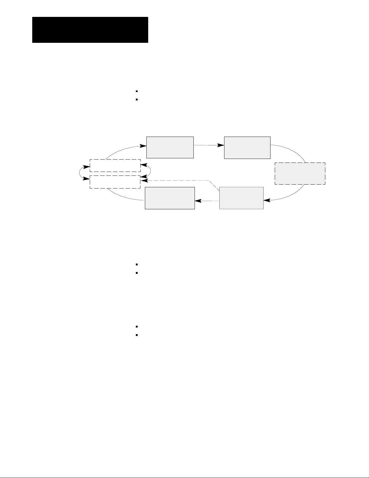
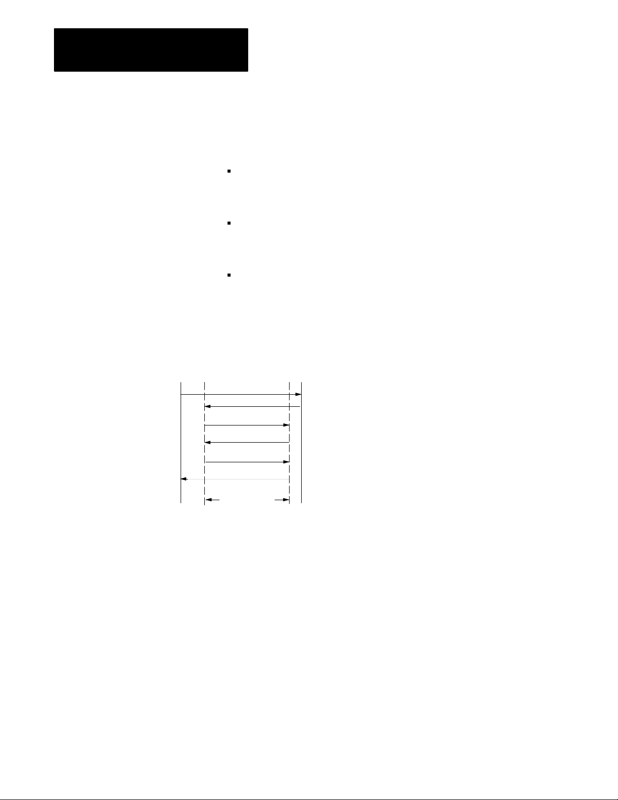
Figure 1.1
Clamp
1st
Close
Open
Slow
Portion of a T
ypical Machine Cycle
2nd
Close
3rd
Open
3rd
Close
Low Pressure
Close
2nd
Open
Clamp Close
Inject
1st
Open
Three separate clamp close profiles may be configured:
first close
second close
third close
You may select from these control modes:
velocity vs. position
pressure vs. position
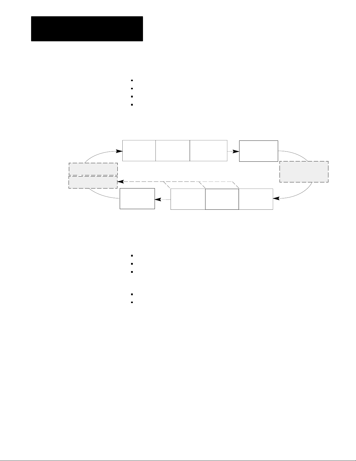
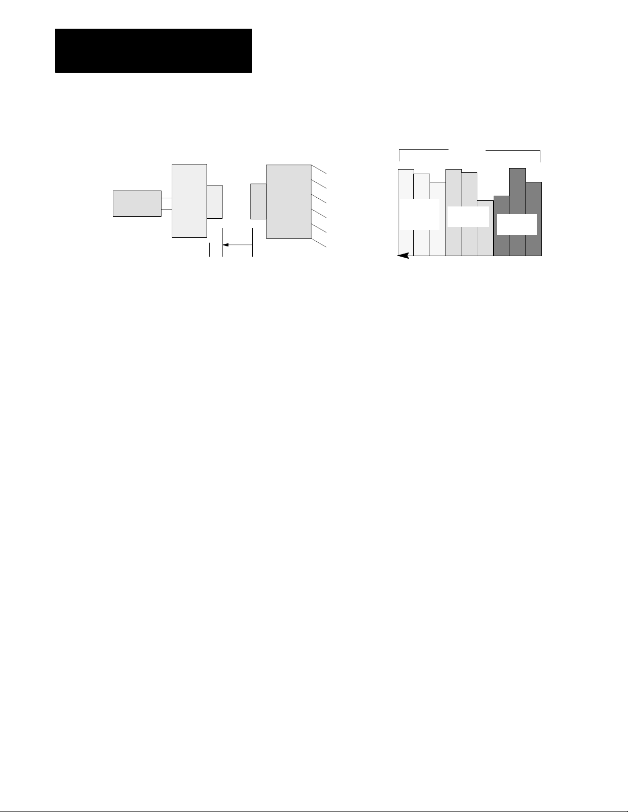
Use Clamp Close to move the platen from the fully open position (L) to
some position X at a relatively high velocity or pressure. X is a position
relatively close to the stationary platen yet far enough away to allow
deceleration into Low Pressure Close. This prevents the platens from
coming together at a high velocity.
1-2
Page 14
Chapter 1
Overview of the Clamp and Eject Mode
Clamp
Cylinder
L
Moving
Platen
Figure 1.2
Example
Clamp Close
0
X
Stationary
Platen
Velocity
1st
Close
Profile
2nd
Close
Profile
Position
3rd
Close
Profile
Three different close profiles have been provided to allow you to initiate
the following operations between profiles:
pick up the 3rd plate of a mold (on a floating 3-plate mold) or set cores
program other events for all valves
either automatically bridge between profiles or allow user programming
to decide when to begin the next profile
Each of these three profiles is subdivided into three position segments
(shown above each profile as in Figure 1.3). You can change clamp
velocity or pressure up to three times in each profile, or up to nine times
for the entire clamp close phase.
Clamp
Cylinder
L
Moving
Platen
Figure 1.3
Example
Clamp Close Position Segments
Stationary
Platen
0
X
11
1st
Close
Profile
Velocity
Segments
2
3
2nd
Close
Profile
Position
2
1
3
3rd
Close
Profile
2
3
Important: You may use as many or as few profiles and/or segments
within profiles as needed for your molding application. If using a single
close fast motion, use the first segment of the 1st close profile. The Low
Pressure Close Profile must follow.
After completing the last segment in each profile, the QDC module either
switches immediately to the next programmed segment of the next desired
profile or waits for a command from your PLC program to continue.
After completing the last configured close profile, the QDC module either
switches immediately to the first programmed segment of Low Pressure
Close, or waits for a command from your PLC program to continue.
1-3
Page 15

Chapter 1
Overview of the Clamp and Eject Mode
Low Pressure Close
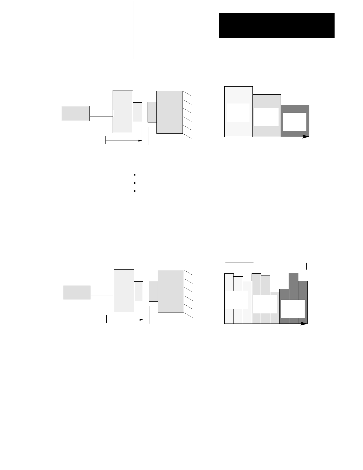
Use the Low Pressure Close Profile to decelerate closing motion to guard
against damaging the mold halves and detect for part obstructions. The
pressure setpoint that you select to control low pressure close should
prohibit the mold from fully closing if there is an obstruction. Up to two
low pressure close profile segments may be used.
You will use the pressure vs. position control mode for low pressure close.
Clamp
Cylinder
Figure 1.4
Example
Low Pressure Close
Moving
Platen
L
0
X
Stationary
Platen
Low Pressure Close
Segments
1
2
Pressure
Position
Important: If you need only one Low Pressure Close segment, configure
the 1st segment of the Low Pressure Close Profile.
The QDC notifies your PLC program when this profile is complete and
automatically uses end-of low pressure close set-output values to build
tonnage (on a hydraulic machine) or lockup your toggle (on a toggle
machine).
1-4
Page 16
Chapter 1
Overview of the Clamp and Eject Mode
Clamp Open
You can open the mold fast with three profiles of the Clamp Open phase:
first open
second open
third open
You may select from these control modes:
velocity vs. position
pressure vs. position
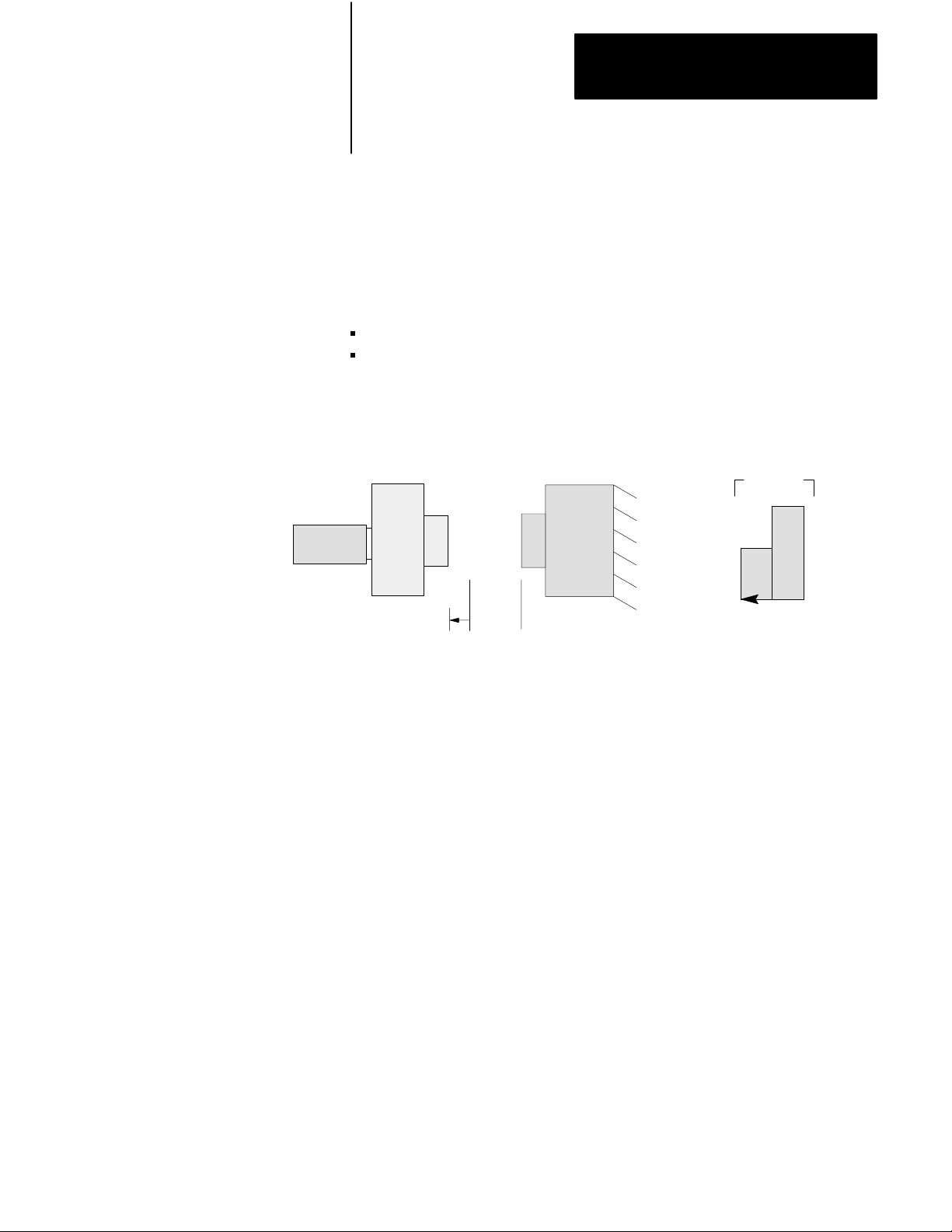
Use Clamp Open to move the platen from the fully closed position (0) to
some position Y at a relatively high velocity or pressure. Y is a position
relatively close to your fully open position (L), yet far enough away to
allow deceleration into Open Slow. This is to increase positioning
accuracy at the full open position (L).
Clamp
Cylinder
Moving
Platen
Figure 1.5
Example
L0
Y
Clamp Open
Stationary
Platen
Three different open profiles have been provided to allow you to initiate
the following operations between profiles:
drop off the third plate of a mold (on a floating 3-plate mold) or pull
cores
program other events for all valves
either automatically bridge between profiles or allow user programming
to decide when to begin the next profile.
Each of these three profiles is subdivided into three position segments
(shown above each profile in Figure 1.6). You can change clamp velocity
or pressure up to three times in each profile, or up to nine times for the
entire clamp open phase.
Velocity
3rd
Open
Profile
2nd
Open
Profile
Position
1st
Open
Profile
1-5
Page 17
Chapter 1
Overview of the Clamp and Eject Mode
Clamp
Cylinder
Moving
Platen
Figure 1.6
Example
L0
Y
Clamp Open Position Segments
Stationary
Platen
33
3rd
Open
Profile
Velocity
Segments
2
1
2nd Open
Profile
Position
2
3
1
1st Open
Profile
Important: You may use as many or as few profiles and/or segments
within profiles as needed. If using a single open motion, use the first
segment of the 1st open profile. The Open Slow Profile must follow.
After completing the last segment in each profile, the QDC module either
switches immediately to the next programmed segment of the next
programmed profile or waits for a command from your PLC program to
continue.
2
1
After completing the last configured open profile, the QDC module either
switches immediately to the first programmed segment of Open Slow, or
waits for a command from your PLC program to continue.
1-6
Page 18
Chapter 1
Overview of the Clamp and Eject Mode
Open Slow
Use the Open Slow Profile to accurately position the clamp for ejecting the
part(s). You may decelerate clamp motion twice with this profile using up
to two profile segments.
You may select from these control modes:
velocity vs. position
pressure vs. position
Figure 1.7
Example
Clamp
Cylinder
Open Slow
Moving
Platen
L0Y
Stationary
Platen
Open Slow
Segments
2
Velocity
Position
Important: If you need only one open slow motion, configure only the 1st
segment of the Open Slow Profile.
1
1-7
Page 19
Chapter 1
Overview of the Clamp and Eject Mode
Ejector Control
Ejector retract
Ejector advance
In this section, we describe Eject operation for expelling parts from the
mold. The operation consists of:
ejector advance
ejector retract
Figure 1.8
and Eject Portion of a T
Clamp
Clamp Close
(Multiphase)
Open Slow
ypical Machine Cycle
Low Pressure
Close
Inject
Clamp Open
(Multiphase)
Ejector Advance
The QDC module starts advancing the ejector after detecting either one of
these events that you configure/program:
clamp position reaching a pre-determined setpoint
command from the user PLC program
You may advance the ejector while the clamp is still opening the mold, or
wait until the mold is fully open.
Up to three ejector advance profile segments may be used. You may select
from these control modes:
velocity vs. position
pressure vs. position
1-8
Page 20
Chapter 1
Overview of the Clamp and Eject Mode
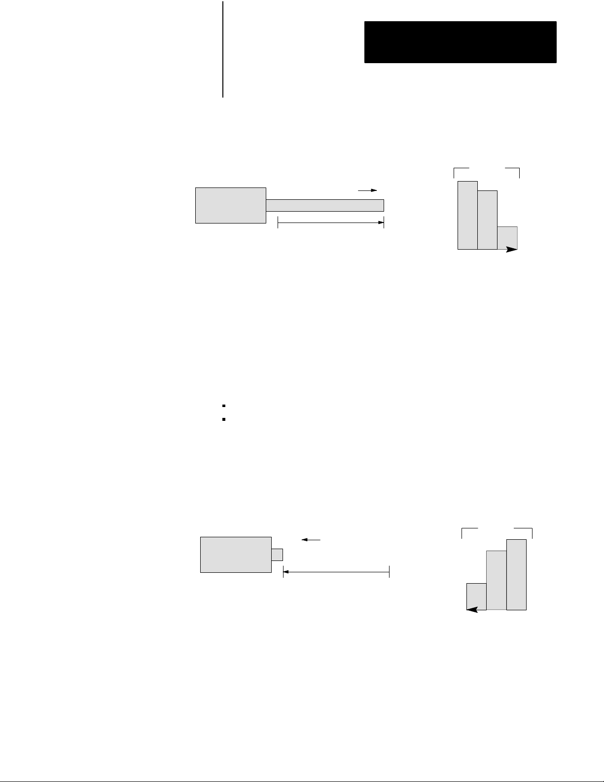
Figure 1.9
Example
Ejector
Ejector Advance
0
Velocity
Fully Advanced Position
Ejector Advance
1
Velocity
Position
Segments
2
3
Important: If you need only one ejector advance motion, configure only
the 1st Advance segment.
Ejector Retract
After the ejector advance is completed, ejector retract is executed. Similar
to advancing the ejector, you retract it with up to three profile segments.
You may select from these control modes:
velocity vs. position
pressure vs. position
Figure 1.10
Example
Ejector
Ejector Retract
0
Velocity
Fully Advanced Position
Ejector Retract
3
Velocity
Position
Segments
2
1
1-9
Page 21
Chapter 1
Overview of the Clamp and Eject Mode
Other Eject Features
The QDC Module gives you the following additional features:
the ability to repeat the ejector cycle a number of times, changing from
advance to retract determined either automatically or by command from
your PLC program
Ejector Forward Dwell - the ability to pause after completing the first or
last ejector advance stroke. Use this feature so a robot can pick off a
part when ejectors are fully extended
Ejector “Tip” Strokes - the ability to “shake” the part off the ejector.
You may program interim single-segment advance and retract tip strokes
that occur after the first advance stroke and before the last retract stroke
Full
Retract
Figure 1.11
Advance,
First Full Advance
Tip Retract
Tip Advance
Tip Retract
Retract and T
:
:
Last Retract
Tip Strokes
1
ip Strokes
1
1
Full
Advance
= Ejector Forward Dwell
1-10
Page 22

Chapter
Install the QDC Module
2
Chapter
Objectives
Record I/O Ranges
This chapter guides you through the process of installing your QDC
module to assure reliable, safe performance. Major topics described in this
chapter include how to:
set module jumpers
key your I/O rack
install your module
wire I/O devices to your module
ground your system
plan for E-STOPs and Machine Interlocks
To match your QDC module to your I/O devices, record the I/O ranges of
your I/O devices on Worksheet 2-A. You will use this information in this
chapter for setting jumper plugs, and in chapter 3 to configure the module’s
inputs and outputs with software.
Circle or check your selections for I/O ranges on Worksheet 2-A.
Worksheet 2A
I/O Ranges
Record
I/O Connection: Voltage 1: Voltage 2: Current:
Input 1 (Ejector position) 0 to 10V dc 1 to 5V dc 4 to 20 mA
Input 2 (Ejector pressure) 0 to 10V dc 1 to 5V dc 4 to 20 mA
Input 3 (Clamp position) 0 to 10V dc 1 to 5V dc 4 to 20 mA
Input 4 (Clamp pressure) 0 to 10V dc 1 to 5V dc 4 to 20 mA
Output 1 10 to 10V dc 0 to 10V dc 4 to 20 mA
Output 2 10 to 10V dc 0 to 10V dc 4 to 20 mA
Output 3 10 to 10V dc 0 to 10V dc 4 to 20 mA
Output 4 10 to 10V dc 0 to 10V dc 4 to 20 mA
2-1
Page 23

Chapter 2
Install the QDC Module
Set Module Jumpers
Before installing the QDC module, you must use jumper plugs to configure
the I/O ranges that you selected with Worksheet 2-A.
Access and Position the Jumpers
Access the jumpers and set them as follows:
ATTENTION: To avoid damage to internal circuits, observe
handling precautions and rid yourself of any electrostatic
charge. Also, this should be done on an anti-static work station.
1. Remove the label-side cover plate by removing the four screws.
2. Remove the circuit board from the module housing by removing the
two screws located center-front at the swingarm catch.
3. Carefully turn over the circuit board so it is oriented as in figure 2.1.
Handle it by the edges to avoid touching conductors or components.
4. Locate the jumpers (Figure 2.1).
5. Set the jumper plugs as shown in Table 2.A using a small needle-nose
pliers (Figure 2.1).
6. After setting the jumper plugs, re-assemble the module.
2-2
Page 24
Chapter 2
Install the QDC Module
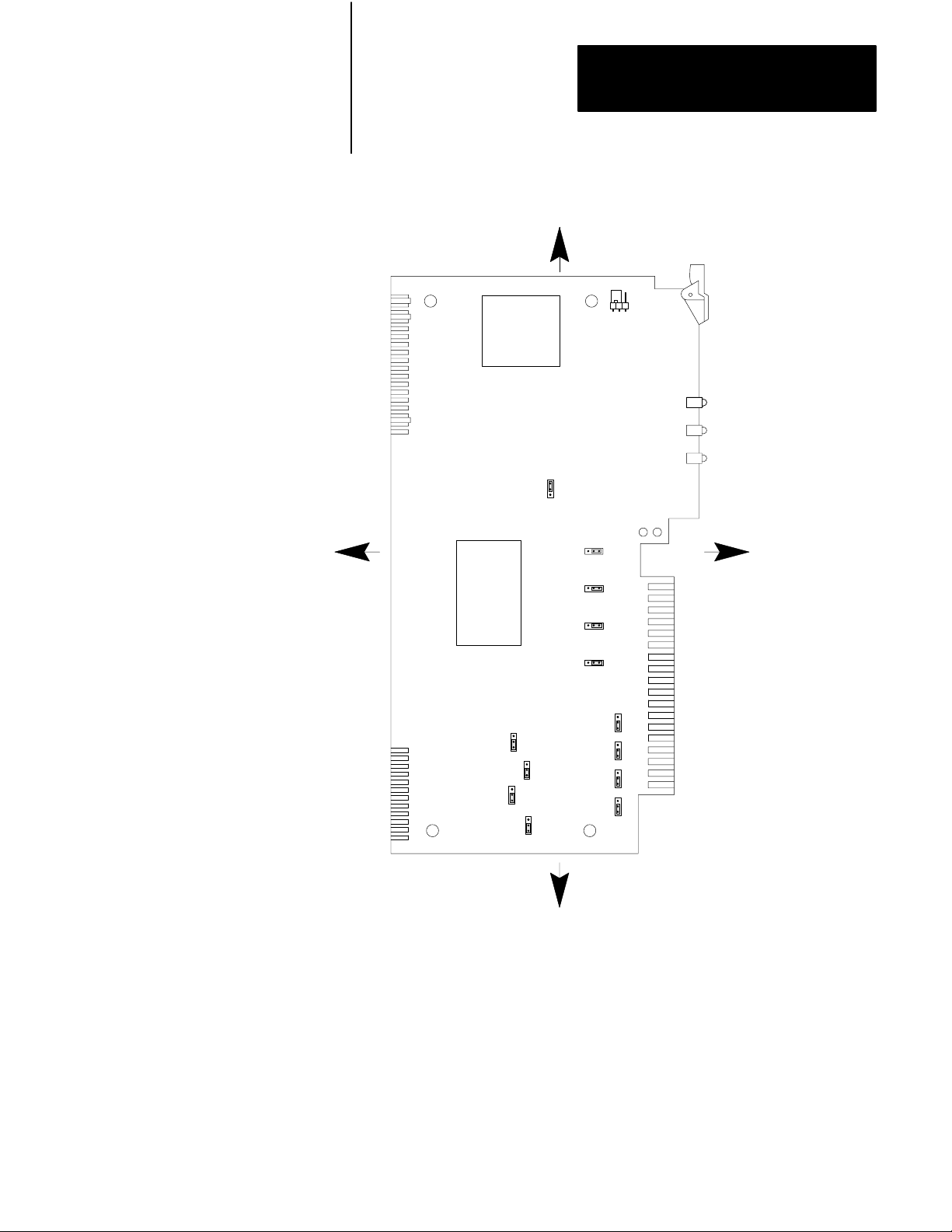
Figure 2.1
Jumper
LEFT
Locations on the QDC Module'
TOP
E5
s Circuit Board
E1
E6
RIGHT
E7
E8
E9
E10
E11
E12
E15
E16
E14
E13
E17
BOTTOM
10908I
Important: We define jumper plug positions as left, right, top, and bottom.
This represents the position of the jumper plug on the 3-pin connector
relative to the orientation of the circuit board shown above.
2-3
Page 25

Chapter 2
Install the QDC Module
Table 2.A
Jumper
Settings
Jumper: Function: Setting:
E1 Run/Calibrate Calibrate = right
Run = left
E5 I/O Density Standard = top
Do not use bottom position
E6
E7
E8
E9
E10
E14
E13
E17
E11
E12
E15
E16
1
Factory Defaults
Input 1 (Ejector position)
Input 2 (Ejector pressure)
Input 3 (Clamp position)
Input 4 (Clamp pressure)
Output 1 (Valve 1)
Output 2 (Valve 2)
Output 3 (Valve 3)
Output 4 (Valve 4)
Output Range 1 (Valve 1)
Output Range 2 (Valve 2)
Output Range 3 (Valve 3)
Output Range 4 (Valve 4)
Voltage = right
Current = left
Current = top
Voltage = bottom
-10 to +10V dc = top
0 to +10V dc or 4 to 20mA = bottom
1
1
1
1
1
Important: If you select current output with jumper plugs E10, E14, E13,
and/or E17, then you must select the 4 to 20mA jumper position with E11,
E12, E15, and/or E16.
ATTENTION: If an output is unconnected, set the jumper
(E11, E12, E15, and/or E16) that corresponds to that output to 0
- 10V dc (bottom position). Setting the jumpers for –10 to
+10V dc and later configuring the output as “unconnected” may
cause the QDC module to output –10V dc on that channel. This
occurs when the system is stopped or when a system reset
occurs and all outputs are forced to 0% (i.e. 0% output equals
–10V dc).
2-4
Page 26
Chapter 2
Install the QDC Module
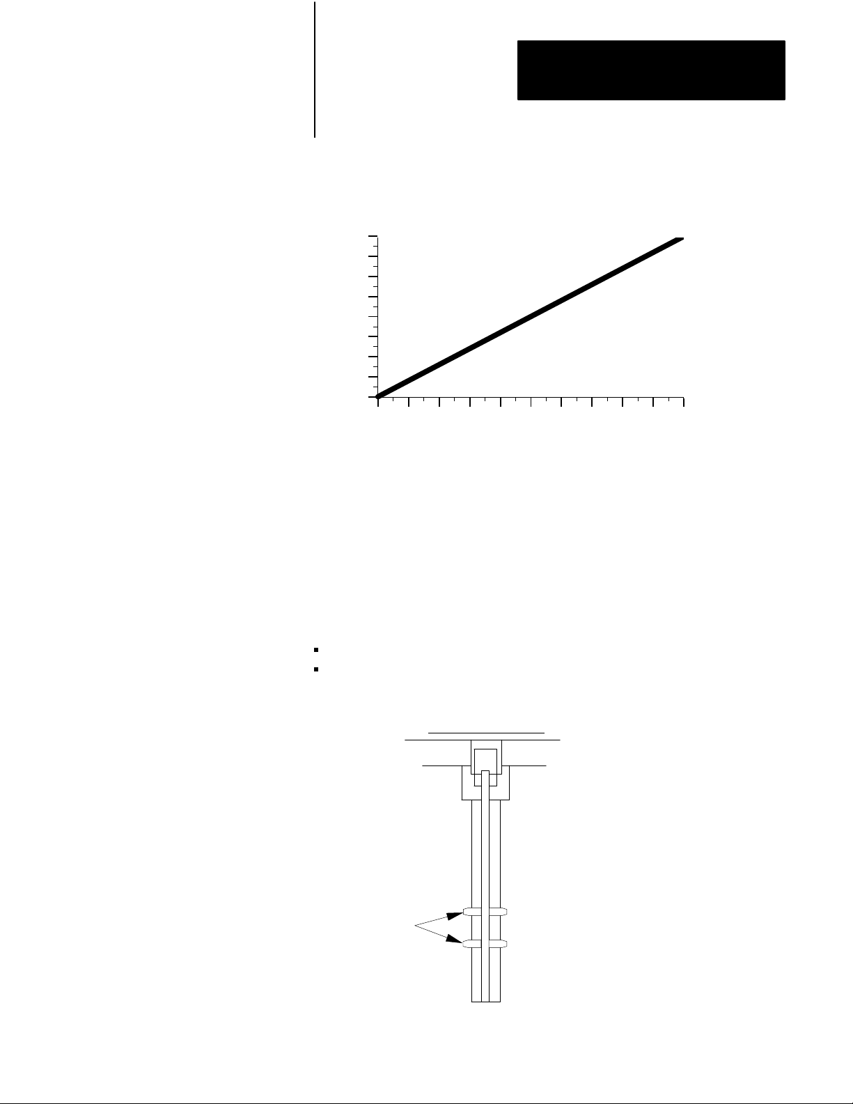
Important: Selecting –10 to +10V dc with jumper E11, E12, E15, and/or
E16 sets the QDC module for bi-directional valve operation. The
relationship to percentage output is as follows:
10
8
5
3
0
-3
Output Voltage
-5
-8
-10
0 102030405060708090100
%
Output Requested
Key Your I/O Chassis
Use the plastic keying bands, shipped with each I/O chassis, for keying I/O
slots to accept only one type of module. This is done to prevent the
inadvertent installation of the wrong module into the wrong slot.
The QDC module is slotted in two places on the rear edge of the circuit
board. The position of the keying bands on the backplane connector must
correspond to these slots to allow insertion of the module.
Place keying bands between the following terminal numbers labeled on the
backplane connector of your I/O chassis (see Figure 2.2):
between 20 and 22
between 26 and 28
Figure 2.2
Positions
Keying
2
4
6
8
10
12
14
16
18
20
Keying
Bands
22
24
26
28
30
32
34
36
1771QDC
12676
2-5
Page 27

Chapter 2
Install the QDC Module
Install Your QDC Module
To install your QDC module in an I/O chassis, complete the following:
1. First, turn off power to the I/O chassis.
ATTENTION: Remove power from the 1771 I/O chassis
backplane and wiring arm before removing or installing a QDC
module.
Failure to remove power from the backplane could cause injury
or equipment damage due to possible unexpected operation.
Failure to remove power from the backplane or wiring arm
could cause module damage, degradation of performance, or
injury.
2. Place the module in the plastic guides on the top and bottom of the
slot that slides the module into position.
Important: Be aware that Pro-Set 600 software expects your Clamp and
Eject QDC module to be placed in slot 1 of your I/O rack. If you choose to
install your QDC module in some other slot, some modifications to your
PLC application program may be necessary (refer to your Pro-Set 600
documentation for details).
3. Do not force the module into its backplane connector. Apply firm,
even pressure on the module to seat it properly.
4. Snap the chassis latch over the top of the module to secure it.
5. Connect the wiring arm to the module.
2-6
Page 28
Chapter 2
Install the QDC Module
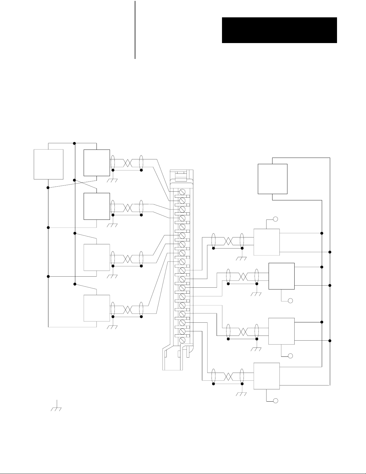
Wire the QDC Module
+
Customer
PS
–
Ejector
Position
Sensor
Ejector
Pressure
Sensor
Clamp
Position
Sensor
Clamp
Pressure
Sensor
Use the swingarm (1771-WF) supplied with the QDC module to wire I/O
devices (Figure 2.3). The field wiring arm lets you install or remove the
QDC module from the I/O chassis without rewiring. Swingarm terminals
are numbered in descending order, from the top down, starting with
terminal 18 (Table 2.B).
Figure 2.3
W
iring and Grounding
I/O
+
–
+
–
+
–
+
–
Input 3
Input 4
Input 1
Input 2
–
Customer
PS
18
+
–
+
Amplifier
Valve 1
+
–
+
–
To Valve 1
+
–
Amplifier
Valve 2
Amplifier
Valve 3
+
–
To Valve 2
+
–
17
16
15
14
13
12
11
10
9
8
7
6
5
4
3
2
1
Output 1
Output 2
Output 3
Earth Ground
Wiring Arm
1771WF
Output 4
+
–
Amplifier
Valve 4
To Valve 3
+
–
To Valve 4
10909I
2-7
Page 29
Chapter 2
Install the QDC Module
Table 2.B
and Eject Mode
Clamp
I/O Terminal Designations
Transducer: I/O Designation: Terminal:
Ejector position Input 1 (+)
(-)
Ejector pressure Input 2 (+)
(-)
Input common 14
Clamp position Input 3 (+)
(-)
Clamp pressure Input 4 (+)
(-)
Valve 1 Output 1 (+)
Output common
Valve 2 Output 2 (+)
Output common
Valve 3 Output 3 (+)
Output common
Valve 4 Output 4 (+)
Output common
Not used 01
18
17
16
15
13
12
11
10
09
08
07
06
05
04
03
02
2-8
ATTENTION: The QDC module has ESD protection to 20KV,
but you can damage the module by accidental application of the
wrong voltage to the I/O terminals. Do not exceed:
This voltage: On these terminals: When in:
+12V dc input (18 thru 10) any mode
+12V dc output (09 thru 02) voltage mode
+24V dc output (09 thru 02) current mode
Page 30
Chapter 2
Install the QDC Module
Ground and Shield
our I/O Devices
Y
Input Sensor
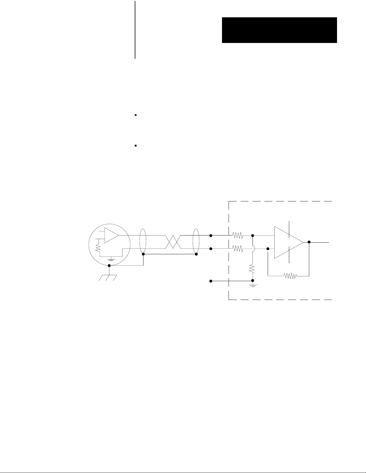
Analog inputs and outputs are sensitive to electrical noise interference.
Take care to shield them properly.
Guidelines:
Use 22-gage (or larger) twisted-pair cable, 100% shielded with drain
wire, such as Belden 8761 (or equivalent). For cable distances over
50 ft, use 18-gage cable such as Belden 8760 (or equivalent)
Ground the cable shield at one end only; generally at the sensor or
amplifier end, not at the I/O chassis (see Figure 2.4 and Figure 2.5)
Figure 2.4
Shielding
Differential Inputs
QDC Module Input
18
17
+15V
+
–
Connect the cable shield
and case ground to earth
ground at the Input Sensor
14
No User Connections.
For Test Purposes, Only.
-15V
Input Module Common
should float
109102
2-9
Page 31

Chapter 2
Install the QDC Module
Figure 2.5
Shielding
QDC Module Output
Singleended Outputs
Customer Valve Amplifier
+
–
9
8
Connect the cable shield
to earth ground at the valve
amplifier
Input
Ground
Chassis Ground
17182
ground the cable shields to a low-impedance earth ground of less than
1/8 ohm
do not connect any ground to input common (terminal 14) except as
specified below under Grounding Exceptions
place high-voltage class A wiring and low-voltage class B wiring in
separate grounded conduits
in parallel runs, separate the class A and B conduit by at least 1 foot
where conduit runs must cross, cross them at right angles
For additional grounding recommendations, refer to the Allen-Bradley
Programmable Controller Wiring and Grounding Guidelines (pub. no.
1770-4.1).
Exceptions
If you experience unacceptable electrical noise interference, then try one or
both of the following alternative grounding connections:
connect the input cable shield to input common (terminal 14) after
disconnecting the shield from the transducer
connect the output cable shield to output common (terminal 8, 6, 4,
and/or 2) after disconnecting it from the valve amplifier
2-10
Page 32

Chapter 2
Install the QDC Module
Plan for ESTOPs and
Machine Interlocks
You must consider the installation of Emergency Stop switches and
machine interlocks when performing the following system tasks:
designing your system
assembling mechanical/hydraulic components
wiring system components
developing system ladder logic
ATTENTION: The Electrical Standard for Industrial
Machinery (NFPA 79-1987) requires an emergency stop that,
when actuated, shall de-energize all electrical power circuits
which provide electrical energy to sustain machine motion.
Maintained contact “Emergency Stop” push buttons are
recommended.
ATTENTION: The American National Standard for Plastics
Machinery -- Horizontal Injection Molding Machines -- for
Construction, Care, and Use (ANSI B151.1-1984) requires
hydraulic, mechanical, and electrical interlocks to prevent
inadvertent clamp closing with a safety gate in an open position.
In addition, we strongly recommend that the electrical
interlocks consist of redundant devices and that the control
circuit be so arranged that malfunction or improper sequencing
of either redundant device prevents further operation of the
machine.
ATTENTION: NEMA Standards Publication ICS1.1, Safety
guidelines for the Application, Installation, and Maintenance of
Solid State Control recommends that the emergency stop and
safety gate electrical interlocks should directly control their
appropriate functions through an electromechanical device
independent of the solid state logic.
The next page shows an illustration of a typical grounded PLC power
distribution circuit. For ungrounded systems or for more information on
grounding and wiring guidelines, refer to Allen-Bradley Programmable
Controller Wiring and Grounding Guidelines (pub. no. 1770-4.1) .
2-11
Page 33

Chapter 2
Install the QDC Module
Disconnect
Figure 2.6
PLC Power Distribution with Interlocks
Typical
L1
L2
L3
Incoming
AC
Use any number
of E-Stop switches
in Series
CRM
Input
Device
1FU
2FU
3FU
H
H
1
H
3
4
H
2
Step-down
Transformer
4
FUSE
X
X
1
2
Start
CRM
I/O Chassis
Power Supply
1
LN
GND
3
** See WARNING for Interlock Wiring Instructions **
2
Output
Input
Device
Module
Wiring
Arm
Output
Module
Wiring
Arm
CRM
1
5
L1
L2
L3
Back-Panel
Ground Bus
Equipment
Grounding
Conductors
CRM
To Motor
Starters
Enclosure
Wall
Grounding Electrode
Conductor to
Grounding Electrode
System
Connect
When
Applicable
User DC
Supply
+–
To DC I/O
Devices
1
To minimize EMI generation, you should connect a suppression network: for 120V AC, use Allen-Bradley
cat. no. 700-N24; for 220/240V AC, use cat. no. 599-KA04.
2
To minimize EMI generation, you should connect a suppression network: for 120V AC, use Allen-Bradley
cat. no. 599-K04; for 220/240V AC, use cat. no. 599-KA04.
3
For a power supply with a groundable chassis, this represents connection to the chassis only. For a power supply
without a groundable chassis, this represents connection to both the chassis and the GND terminal.
In many applications, a second transformer provides power to the input circuits and power supplies for isolation from the
4
output circuits.
Reference the current NEC code and ANSI B151.1 for additional wiring guidelines.
•
5
To minimize EMI generation, suppression networks should be connected across coils of electromagnetic devices.
•
2-12
10907I
Page 34

Chapter
Configure the QDC Module's
Inputs and Outputs
3
Chapter
Objectives
Your QDC module needs to know the characteristics of your clamp and
ejector sensors. In this chapter, we describe how to determine these
characteristics and download them to the QDC module. Topics include:
signal ranges from pressure and position sensors
minimum and maximum sensor signals corresponding to
minimum and maximum pressures and positions
alarm values and travel limits
We describe how to configure the QDC module in these sections:
select module parameters and I/O ranges
determine initial sensor configuration values
download configuration values to the QDC module
use the set-output operation to move the clamp and ejector
complete sensor configuration
optional sensor configurations
Important: You must properly configure the QDC module using
procedures in this chapter before attempting further configurations.
Important: If you have not already done so, install Pro-Set 600 software.
The procedures in this and the next several chapters assume that you have.
3-1
Page 35

Chapter 3
Configure the QDC Module's
Inputs and Outputs
Command and Status Blocks Used
The following table contains a list of command blocks you are to configure
throughout the course of this chapter. You may reference these command
blocks in sections 1 and 3 of the Plastic Molding Module Reference
Manual (pub. no. 1771-6.5.88).
Block: Type: Use in this Chapter: ProSet 600 Files:
Select
Module Parameters
and I/O Ranges
Module Configuration (MCC) Command Configure Module I/O
operating parameters
Module Configuration (MCC) Command Select Input Ranges for I/O B35
Module Configuration (MCC) Command Select Output Ranges for I/O B35
Module Configuration (MCC) Command Determine Initial Sensor Con
figuration values
Module Configuration (MCC) Command Determine Software Travel
Limits
Module Configuration (MCC) Command Enter Pressurealarm and
Timedelay Setpoints
B35
N41
N41
N41
You select module parameters and I/O ranges by setting configuration bits
in control words. First determine and write down correct settings using
Worksheet 3-A thru Worksheet 3-C as follows:
To Configure: In Control Word: Starting At
ProSet 600 Address:
Module Parameters MCC02 B35/528 Worksheet 3-A
Use this Worksheet:
3-2
Input Range MCC03 B35/544 Worksheet 3-B
Output Range MCC04 B35/560 Worksheet 3-C
Page 36

Worksheet 3A
Selecting Module Parameters
Chapter 3
Configure the QDC Module's
Inputs and Outputs
Control W
ProSet 600 Addr. B35/bit
ord MCC02Bxx
15 14 13 12
11 10
09 08 07 06 05 04 03 02 01 00
543 542 541 540 539 538 537 536 535 534 533 532 531 530 529 528
Value 0 0 0 0 0 0 0 0 0 0 1 0 1 0 0
Code:
0
or 1
Your value
Required initial value
loaded by ProSet 600
Select System Operation with bits 05 and 04
Clamp and Eject 1 0
Select Singleunit Operation with bit 03 = 1
(0 generates a programming error)
Select English = 0 or
metric = 1 with bit 00
Example: If you select Clamp and Eject operation with English units:
MCC02 = 00000000 00101000
Selecting I/O Ranges for your Sensors
Next, configure the QDC module’s I/O ranges to match the machine
sensors and valves. Refer to Worksheet 2-A from chapter 2 which you
filled out when setting the QDC module’s jumpers. Apply this information
to Worksheet 3-B for input ranges and Worksheet 3-C for output ranges.
Worksheet 3B
Input Ranges for your Sensors
11 10
09 08 07 06 05 04 03 02 01 00
Control W
ord MCC03Bxx
ProSet 600 Addr. B35/bit
Selecting
15 14 13 12
559 558 557 556 555 554 553 552 551 550 549 548 547 546 545 544
Value 1 1 1 1 1 1 1 1
Select Input 4 (Clamp Pressure) Range with bits 07, 06
Select Input 3 (Clamp Position) Range with bits 05, 04
Code:
0
or 1
Your value
Required initial value
loaded by ProSet 600
Select Input 2 (Ejector Pressure) Range with bits 03, 02
Select Input 1 (Ejector Position) Range with bits 01, 00
Example: If you select an input range of 4-20mA for all four inputs,
MCC03 = 11111111 10101010.
Important: Software input/output selections must match the jumper
settings for each respective input/output.
Input Range
0 - 10V dc 0 0
1 - 5V dc 0 1
4 - 20 mA 1 0
Not connected 1 1
3-3
Page 37

Chapter 3
Configure the QDC Module's
Inputs and Outputs
Worksheet 3C
Selecting Output Ranges for your V
alves
Control W
ProSet 600 Addr. B35/bit
Value 1 1 1 1 1 1 1 1
Code:
ord MCC04Bxx
0
or 1
Your value
Required initial value
loaded by ProSet 600
15 14 13 12
575 574 573 572 571 570 569 568 567 566 565 564 563 562 561 560
Select Output 4 Range with bits 07, 06
Select Output 3 Range with bits 05, 04
Select Output 2 Range with bits 03, 02
Select
Output 1 Range with bits 01, 00
11 10
09 08 07 06 05 04 03 02 01 00
Example: If you select 0-10 vdc for all four output ranges,
MCC04 = 11111111 01010101.
Important: Software input/output selections must match the jumper
settings for each respective input/output.
Output Range
-10 to +10 vdc 0 0
0 to +10 vdc 0 1
4 to 20 mA 1 0
Not connected 1 1
3-4
Page 38

Chapter 3
Configure the QDC Module's
Inputs and Outputs
Determine
Initial
Sensorconfiguration Values
To determine initial sensor configuration values, refer to Table 3.A, and to
the specifications that accompanied your sensors, valves, and cylinders.
Write down applicable values on Worksheet 3-D.
Important: You must enter floating-point numbers and percentages as
integers, so we recommend that you write them in Worksheet 3-D in the
following format: Use an assumed decimal point position that depends on
the range value. For example:
If the Range is: And You Want to
Enter this Value:
0 099.99% 75% 07500
0 99.99 inch 7.32 inch 00732
0 0999.9 mm 432.6 mm 4326
4.00 020.00 mA 16mA 01600
0 010.00 vdc 5.6 vdc 00560
0 009.99 sec 0.47 sec 00047
0 09999 PSI 321 PSI 00321
0 0999.9 Bar 222 Bar 2220
Use this
Format:
Table 3.A
Determining
Category: If: Then Use a Value Equal to:
Minimum Position
(Lines 1 and 9)
Maximum Position
(Lines 2 and 10)
Analog Signal @ Min Position your sensors are forwardacting low end of your selected range
(Line 3 and 11) your sensors are reverseacting high end of your selected range
Analog Signal @ Max Position your sensors are forwardacting high end of your selected range
(Line 4 and 12) your sensors are reverseacting low end of your selected range
Minimum Pressure
(Lines 5 and 13)
Maximum Pressure
(Lines 6 and 14)
Initial Sensorconfiguration V
N/A zero
the
mold is fully closed, the
and the ejector retract position is zero
N/A minimum range value specified by the
N/A maximum range value specified by the
alues for W
position is zero
orksheet 3D
full travel of the sensor
manufacturer
manufacturer
3-5
Page 39

Chapter 3
Configure the QDC Module's
Inputs and Outputs
Category: If: Then Use a Value Equal to:
Analog Signal @ Min Pressure your sensors are forwardacting low end of your selected range
(Lines 7 and 15) your sensors are reverseacting high end of your selected range
Analog Signal @ Max Pressure your sensors are forwardacting high end of your selected range
(Lines 8 and 16) your sensors are reverseacting low end of your selected range
T
able 3.A (continued)
Determining Initial Sensorconfiguration V
alues for W
orksheet 3D
Worksheet 3D
Determining
Initial Sensorconfiguration V
alues
Enter Your Initial Values Here
Input Control Word ProSet
1 MCC37 N41:33 0 Minimum Ejector Position Ejector Axis Measured from zero
MCC38 N41:34 Maximum Ejector Position Ejector Axis Measured from zero
MCC39 N41:35 Analog Signal @ Min Ejector Position Input Signal Range
MCC40 N41:36 Analog Signal @ Max Ejector Position Input Signal Range
2 MCC45 N41:41 0 Minimum Ejector Pressure Ejector Pressure
MCC46 N41:42 Maximum Ejector Pressure Ejector Pressure
MCC47 N41:43 Analog Signal @ Min Ejector Pressure Input Signal Range
MCC48 N41:44 Analog Signal @ Max Ejector Pressure Input Signal Range
3 MCC23 N41:19 0 Minimum Clamp Position Clamp Axis Measured from zero
MCC24 N41:20 Maximum Clamp Position Clamp Axis Measured from zero
MCC25 N41:21 Analog Signal @ Min Clamp Position Input Signal Range
MCC26 N41.22 Analog Signal @ Max Clamp Position Input Signal Range
4 MCC31 N41:27 0 Minimum Clamp Pressure Clamp Pressure
MCC32 N41:28 Maximum Clamp Pressure Clamp Pressure
MCC33 N41:29 Analog Signal @ Min Clamp Pressure Input Signal Range
MCC34 N41:30 Analog Signal @ Max Clamp Pressure Input Signal Range
1
Incremental Distance
00.00
000.0 to 999.9 Millimeters
600 Addr
to 99.99 Inches
. Value Description Units
2
Input
Signal Range
00.00 to 10.00V dc or
01.00 to 05.00V dc or
04.00 to 20.00MADC
3
2
2
3
3
2
2
2
2
3
3
2
2
Pressure
0000 to 9999 PSI
000.0 to 999.9 Bar
1
1
1
1
3-6
Page 40

Chapter 3
Configure the QDC Module's
Inputs and Outputs
Download MCC Values to the QDC Module
Use this download procedure now and later in this chapter. The procedure
requires you to complete the following general steps:
enter MCC values into the PLC-5 data table
download them to the QDC module (PLC-5 processor in run mode)
correct any data entry (programming) errors
Next we describe the general steps:
Enter MCC Values into Your PLC5 Data Table
With your programming terminal, enter values from Worksheet 3-A thru
Worksheet 3-D into your PLC-5 data table as follows:
1. Switch the PLC-5 processor to program mode.
2. Display your PLC-5 data table.
3. Locate the data file for storing the MCC block. PLC-5 data table
word addresses are listed on the worksheets.
4. Enter the value for each word and bit.
When you enter bit selections in words prefixed with file identifier B
(example: B34), the PLC-5 processor automatically switches the radix to
binary format so you can conveniently enter binary data.
Download MCC Values to the QDC Module
To download the MCC block to the QDC module, switch the PLC-5
processor from program to run mode. Pro-Set 600 software downloads the
MCC block to the QDC module for you.
Important: You can verify that the MCC block was successfully downloaded or that you made a data entry (programming) error by evaluating
the following words that Pro-Set 600 software continuously reports to the
PLC-5 processor.
If: And: Then:
SYS01B08 = 1
(B34/8)
SYS19B00 = 1
(B34/288)
N/A QDC module accepted a valid MCC.
SYS61 = 1
(ID code for MCC block
stored in N40:213)
You made a programming error in MCC.
Read the error code in SYS62 (N40:214) , and
look up the error in Section 2 of QDC Module
Reference Manual, publication 17716.5.88.
3-7
Page 41

Chapter 3
Configure the QDC Module's
Inputs and Outputs
Important: Pro-Set 600 software downloads all command blocks when
your PLC-5 processor enters run mode after a valid MCC block is
accepted. All programming errors reported in SYS62 (N40:214) are
referenced to the MCC block until SYS01-B08 = 1.
Correct Any Dataentry (Programming) Errors in MCC
Upon receipt of the MCC block, the QDC module tests data for data-entry
errors, such as a value out of range. When it detects an error, the QDC
module halts operation until you correct the error. For a complete list of
error codes to help you correct a programming error, refer to Section 2 of
the Plastic Molding Module Reference Manual, publication 1771-6.5.88.
You must correct errors by entering the changed configuration values into
your PLC-5 data table and downloading the new values to the QDC
module as outlined above. Pro-Set 600 software continues to attempt to
download the MCC block to the QDC module until an MCC block is
accepted and the QDC module returns SYS01-B08 = 1.
Important: The QDC module must receive a valid MCC block before you
can download additional blocks.
3-8
Page 42

Chapter 3
Configure the QDC Module's
Inputs and Outputs
Use the Setoutput
Operation to Move the
Clamp and Ejector
To finish configuring the QDC module, you actuate the clamp and ejector
with the QDC module’s set-output operation. Set-output applies
percentage output values to your valves to move your clamp or ejector
cylinder in a controllable fashion. You apply a percentage output signal to
each module output so you can move each actuator over its intended range.
Sensor spanning values can then be refined per the actual values monitored
by the QDC module.
ATTENTION: Do not rely on pressure valves connected to the
QDC module for pressure relief. Use them only for pressure
control below the setting of the system pressure-relief valve.
ATTENTION: A value of zero in set-output words N41:121 N41:124 does not necessarily correspond to zero pressure or
flow. If you have configured jumper E11, E12, E15, and/or E16
for bi-directional valve operation, an output of 0% gives
–10vdc, 50% gives 0vdc (see chart). Amplifier electronics or
spool-null offsets may also allow pressure or flow at zero volts
signal input. Consult your valve and amplifier specifications for
more details.
Output Voltage
-10
10
8
5
3
0
-3
-5
-8
0 102030405060708090100
%
Output Requested
3-9
Page 43

Chapter 3
Configure the QDC Module's
Inputs and Outputs
ATTENTION: As soon as you enable set-output operation, the
QDC module’s outputs drive the connected valves according to
the values you entered into DYC09 - DYC12 (Pro-Set 600
words N41:121 - N41:124). Be sure these values RESULT IN
NO MOVEMENT until you adjust them one-at-a-time with
your programming terminal in the procedures that follow.
Actuating the Clamp and Ejector with Setoutput Operation
1. Enter values that result in no motion in these DYC words:
Output: In Data Word: At ProSet 600
Address:
1 DYC09 N41:121
2 DYC10 N41:122
3 DYC11 N41:123
4 DYC12 N41:124
2. Enable set-output operation by entering a 1 in DYC01-B08 (Pro-Set
600 address B35/392). The QDC module sets outputs 1 - 4 to
percentage values that you entered in DYC09 - DYC12 respectively.
3. With your programming terminal, slowly increase the %-output value
of one output as you observe the corresponding movement.
Important: The DYC is constantly transferred to the QDC module by
Pro-Set 600 software, so changes you make to %-output values are
immediately implemented.
3-10
Page 44

Chapter 3
Configure the QDC Module's
Inputs and Outputs
Complete your Sensor Configuration
Enter Your Final Sensorconfiguration V
alues Here
Complete the procedure for configuring the QDC module to match its
sensors by spanning them over their intended range with the machine in
operation. Here we describe how you determine:
clamp position sensor values
ejector position sensor values
clamp pressure sensor values
ejector pressure sensor values
In the procedures that follow, measure and record:
minimum and maximum positions
corresponding signal values
minimum and maximum pressures
corresponding signal values
After determining these values, write them down on Worksheet 3-E.
Important: You must complete this configuration before proceeding to
any other chapters on module configuration.
Worksheet 3E
Sensorconfiguration V
Final
alues
Input Control Word ProSet 600 Addr. Value Description Units
1 MCC37 N41:33 0 Minimum Ejector Position Ejector Axis Measured from zero
MCC38 N41:34 Maximum Ejector Position Ejector Axis Measured from zero
MCC39 N41:35 Analog Signal @ Min Ejector Position Input Signal Range
MCC40 N41:36 Analog Signal @ Max Ejector Position Input Signal Range
2 MCC45 N41:41 0 Minimum Ejector Pressure Ejector Pressure
MCC46 N41:42 Maximum Ejector Pressure Ejector Pressure
MCC47 N41:43 Analog Signal @ Min Ejector Pressure Input Signal Range
MCC48 N41:44 Analog Signal @ Max Ejector Pressure Input Signal Range
3 MCC23 N41:19 0 Minimum Clamp Position Clamp Axis Measured from zero
MCC24 N41:20 Maximum Clamp Position Clamp Axis Measured from zero
MCC25 N41:21 Analog Signal @ Min Clamp Position Input Signal Range
MCC26 N41:22 Analog Signal @ Max Clamp Position Input Signal Range
4 MCC31 N41:27 0 Minimum Clamp Pressure Clamp Pressure
MCC32 N41:28 Maximum Clamp Pressure Clamp Pressure
MCC33 N41:29 Analog Signal @ Min Clamp Pressure Input Signal Range
MCC34 N41:30 Analog Signal @ Max Clamp Pressure Input Signal Range
1
Incremental Distance
00.00
to 99.99 Inches
000.0 to 999.9 Millimeters
2
Input Signal Range
00.00 to 10.00V dc or
01.00 to 05.00V dc or
04.00 to 20.00MADC
3
Pressure
0000 to 9999 PSI
000.0 to 999.9 Bar
2
2
3
3
2
2
2
2
3
3
2
2
1
1
1
1
3-11
Page 45

Chapter 3
Configure the QDC Module's
Inputs and Outputs
Determine Clamp Position Sensor Values
Important: The following procedure and subsequent set-up information
must be utilized for every different mold used on a hydraulic machine. On
a toggle clamp (with die height adjust), it must be completed only once.
ATTENTION: Incorrect values entered in DYC09 through
DYC12 may result in rapid clamp motion and potential damage
to your mold and cylinder seals. We strongly recommend
utilizing a “dummy” mold on hydraulic machines and no mold
on toggle machines.
To complete the configuration for your clamp position sensor, do the
following:
Important: If your position sensor has zero and span potentiometers to set
the zero reference and linear resolution, do so during this procedure.
1. Move the clamp forward until it reaches its mechanical close stop.
This is the zero position.
2. Remove clamp pressure and/or flow to stop clamp movement.
3. Record this position value (usually 0000) on line 9 of Worksheet 3-E
for MCC23.
4. With your programming terminal, read the signal level returned in
SYS35 (Pro-Set 600 address N41:187) from your position sensor.
You may wish to zero your position sensor at this time.
5. Record this value on line 11 of Worksheet 3-E for MCC25 (should be
at minimum signal if you zeroed your position sensor in step 4).
6. Move the clamp backward to the mechanical open stop.
7. Remove clamp pressure and/or flow to stop clamp movement.
8. Measure the distance travelled by the clamp.
3-12
9. Record this distance on line 10 of Worksheet 3-E for MCC24.
10.With your programming terminal, read the signal level returned in
SYS35 (Pro-Set 600 address N41:187) from your positioning sensor.
You may wish to span your position sensor at this time.
Page 46

Chapter 3
Configure the QDC Module's
Inputs and Outputs
11. Record this value on line 12 of Worksheet 3-E for MCC26.
You may now download your adjusted values to the QDC module using
the MCC download procedure presented earlier in this chapter.
Determine Ejector Position Sensor Values
ATTENTION: Make sure your clamp is open sufficiently to
allow full ejector travel before proceeding.
To complete the configuration for your ejector position sensor, do the
following:
Important: If your position sensor has zero and span potentiometers to set
the zero reference and linear resolution, do so during this procedure.
1. Move the ejector backward to the mechanical retract stop. This is the
zero position.
2. Remove ejector pressure and/or flow to stop ejector movement.
3. Record this position value (usually 0000) on line 1 of Worksheet 3-E
for MCC37.
4. With your programming terminal, read the signal level returned in
SYS33 (Pro-Set 600 address N41:185) from your position sensor.
You may wish to zero your position sensor at this time.
5. Record this value on line 3 of Worksheet 3-E for MCC39 (should be
at minimum signal if you zeroed your position sensor in step 4).
6. Move the ejector forward to the mechanical advance stop.
7. Remove ejector pressure and/or flow to stop ejector movement.
8. Measure the distance travelled by the ejector.
9. Record this distance on line 2 of Worksheet 3-E for MCC38.
10.With your programming terminal, read the signal level returned in
SYS33 (Pro-Set 600 address N41:185) from your positioning sensor.
You may wish to span your sensor at this time.
11. Record this value on line 4 of Worksheet 3-E for MCC40.
3-13
Page 47

Chapter 3
Configure the QDC Module's
Inputs and Outputs
12.Return your ejector to the fully retracted position.
You may now download your adjusted values to the QDC module using
the MCC download procedure presented earlier in this chapter.
Determine Values for the Clamp Pressure Sensor (if used)
To complete the configuration for your clamp pressure sensor, enter
minimum and maximum pressures and corresponding signal levels from
manufacturer’s specifications in MCC31 - MCC34. Most applications
require no further spanning. If your application requires greater accuracy,
follow the procedure below:
1. Release system pressure to obtain minimum pressure at the clamp.
2. Read the pressure gauge at the clamp.
3. Record this minimum pressure value (usually 0000) on line 13 of
Worksheet 3-E for MCC31.
4. With your programming terminal, read the signal level returned in
SYS36 (Pro-Set 600 address N41:188) from your pressure sensor.
You may wish to zero your pressure sensor at this time.
5. Record this signal level on line 15 of Worksheet 3-E for MCC33
(should be at min signal if you zeroed your pressure sensor in step 4).
ATTENTION: Use extreme caution during the next steps
because you stress the hydraulic system to its maximum rated
pressure. Loose fittings or faulty components could fail, causing
possible damage to equipment and/or injury to personnel.
6. Re-torque all hydraulic connections and joints before proceeding.
7. Boost system pressure to obtain maximum pressure at the clamp.
Max system pressure may be obtained by positioning the clamp at
full open while keeping the clamp open valve in the maximum open
position. This forces the cylinder to press against the mechanical
limits of its travel and builds max system pressure. Also, if you
wish, you may move the clamp to its full forward (mold close)
position, and allow full system pressure to force the mold closed.
3-14
8. Read the pressure gauge at the clamp (maximum system pressure
should be read at full open or full close) while the clamp is
mechanically bound from moving further.
9. Record this maximum pressure on line 14 of Worksheet 3-E for
MCC32.
Page 48

Chapter 3
Configure the QDC Module's
Inputs and Outputs
10.With your programming terminal, read the signal level returned in
SYS36 (Pro-Set 600 address N41:188) from your pressure sensor.
You may wish to span your pressure sensor at this time.
11. Record this signal level on line 16 of Worksheet 3-E for MCC34.
12.Release pressure.
You may now download your adjusted values to the QDC module using
the MCC download procedure presented earlier in this chapter.
Determine Values for the Ejector Pressure Sensor (if used)
ATTENTION: Make sure your clamp is sufficiently open to
allow full travel of the ejectors without obstruction.
To complete the configuration for your ejector pressure sensor, enter
minimum and maximum pressures and corresponding signal levels from
manufacturer’s specifications in MCC45 - MCC48. If you require greater
accuracy, follow this procedure:
1. Release system pressure to obtain minimum pressure at the ejector.
2. Read the pressure gauge at the ejector.
3. Record this minimum pressure value (usually 0000) on line 5 of
Worksheet 3-E for MCC45.
4. With your programming terminal, read the signal level returned in
SYS34 (Pro-Set 600 address N41:186) from your pressure sensor.
You may wish to zero your pressure sensor at this time.
5. Record this signal level on line 7 of Worksheet 3-E for MCC47
(should be min signal if you zeroed your pressure sensor in step 4).
ATTENTION: Use extreme caution during the next steps
because you stress the hydraulic system to its maximum rated
pressure. A rupture could occur, causing possible damage to
equipment and/or injury to personnel.
6. Re-torque all hydraulic connections and joints before proceeding.
3-15
Page 49

Chapter 3
Configure the QDC Module's
Inputs and Outputs
7. Boost system pressure to obtain maximum pressure at the ejector.
Max system pressure may be obtained by positioning the ejector at
its fully advanced or retracted position while keeping the valve open
that causes motion in that direction. This forces the cylinder to press
against the mechanical limits of its travel and builds max system
pressure.
8. Read the pressure gauge at the ejector (for maximum pressure reading
ejector must be fully forward while the ejector is mechanically bound
from moving farther).
9. Record this maximum pressure on line 6 of Worksheet 3-E for
MCC46.
10.With your programming terminal, read the signal level returned in
SYS34 (Pro-Set 600 address N41:186) from your pressure sensor.
You may wish to span your sensor at this time.
11. Record this signal level on line 8 of Worksheet 3-E for MCC48.
12.Release pressure.
You may now download your adjusted values to the QDC module using
the MCC download procedure presented earlier in this chapter.
3-16
Page 50

Chapter 3
Configure the QDC Module's
Inputs and Outputs
Optional Configurations
Your QDC module also gives the option of configuring the following
features:
Use this Option: For this Benefit:
Software Travel Limits to guard against damaging the mold assembly or seals
Pressure Alarm Time Delay to warn of excessive pressure without nuisance alarms
Digital Filter to compensate for noise on position inputs
Configure Software Travel Limits
You may want to use the software restrictions to stop the travel of your
clamp or ejector before either reaches its maximum limits (configured
earlier in this chapter).
Figure 4.1
Software
Restrictions
Physical Travel Range
dd
Safe Zone
d = deadband
Max SWTL Min SWTL
Max Position Min Position
11019I
During normal machine operation and whenever your cylinder travels
outside the safe zone (outside the specified software travel limits, SWTL),
the QDC module:
sets an alarm status bit
forces its outputs to zero
ignores all profile commands (allowing only set-output and jogs) until
you jog the cylinder back through the deadband into the safe zone at
either end
The deadband guards against sensor noise flickering the SWTL alarms and
requires that the operator jog the cylinder a set distance away from the
software overtravel. We recommend a value of 00.10 inch as a starting
deadband. Your sensor may require a greater deadband.
ATTENTION: The QDC module ignores SWTL alarms when
jogging or when performing a set-output operation.
3-17
Page 51

Chapter 3
Configure the QDC Module's
Inputs and Outputs
Configure the QDC module for SWTL as follows:
1. Determine these SWTL values for clamp and/or ejector travel with
respect to the range of physical travel.
SWTL deadband
Maximum SWTL
Minimum SWTL
2. Record non-zero SWTL values on Worksheet 3-F. Zero values
disable the corresponding SWTLs.
ATTENTION: Leaving your SWTL settings at zero (MCC27,
MCC28, MCC41, MCC42) inhibits the QDC module from
performing this safety function.
Worksheet 3F
Configuration V
SWTL
alues
Enter Your SWTL Configuration Values Here
Control Word ProSet 600 Addr. Value Description Units
MCC27 N41:23 Clamp Minimum SWTL Clamp Axis Measured from zero
MCC28 N41:24 Clamp Maximum SWTL Clamp Axis Measured from zero
MCC29 N41:25 10 Clamp SWTL Deadband As noted
MCC41 N41:37 Ejector Minimum SWTL Ejector Axis Measured from zero
MCC42 N41:38 Ejector Maximum SWTL Ejector Axis Measured from zero
MCC43 N41:39 10 Ejector SWTL Deadband As noted
1
Incremental Distance
00.00 to 99.99 Inches
000.0 to 999.9 Millimeters
1
1
You may now download your adjusted values to the QDC module using
the MCC download procedure presented earlier in this chapter.
1
1
1
1
3-18
Page 52

Chapter 3
Configure the QDC Module's
Inputs and Outputs
Set Up Maximum Pressure Alarms and Time Delays
The QDC module continuously monitors clamp and ejector pressure
inputs. When it detects that the pressure equals or exceeds a preset
pressure alarm setpoint, the QDC module sets an alarm bit. A setpoint of
zero disables the associated alarm.
To guard against nuisance alarms caused by noise spikes or pressure
transients, you can set a time-delay so the QDC module must monitor
continuous excessive pressure for an amount of time before setting the
high pressure alarm. A setpoint of zero disables this delay.
Configure the QDC module for pressure alarms as follows:
1. Determine these values for clamp and/or ejector pressure alarms:
pressure-alarm setpoint
time-delay setpoint
2. Record non-zero setpoints on Worksheet 3-G for the pressure alarms
and time delays you want to use.
3. Download them to the QDC module using the procedures presented
earlier in this chapter.
Worksheet 3G
Pressurealarm
Enter Your Pressurealarm and T
Control Word ProSet 600 Addr. Value Description Units
MCC35 N41:31 Clamp Pressurealarm Setpoint Clamp Pressure
MCC36 N41:32 Clamppressure Timedelay Setpoint Time
MCC49 N41:45 Ejector Pressurealarm Setpoint Ejector Pressure
MCC50 N41:46 Ejectorpressure Timedelay Setpoint Time
1
Time
00.00
and T
imedelay Setpoints
imedelay Values Here
to 00.99 Seconds
2
Pressure
0000 to 9999 PSI
000.0 to 999.9 Bar
Measured in Seconds
Measured in Seconds
2
1
2
1
3-19
Page 53

Chapter 3
Configure the QDC Module's
Inputs and Outputs
Configure a Digital Filter for Position Inputs from Clamp and Ejector
You can enable an optional digital filter on position inputs. This filter is
used to reduce electrical noise from potentiometer-type position sensors or
other external noise picked up by your input circuits.
To determine if you need a digital filter, move the clamp or ejector very
slowly. With your programming terminal, look for erratic position
numbers reported for clamp and/or ejector position by examining these
words:
For this Input: In Word: Look at this ProSet 600 Address:
Clamp SYS27 N41:179
Ejector SYS25 N41:177
Configure the QDC Module for a Digital Input Filter as follows:
To determine the time constant (0 - 00.10 sec), start with a small value
such as 00.01. A value of zero disables the filter.
To Filter this Input: In Word: Enter a Filter Time Constant in:
Clamp MCC30 N41:26
Ejector MCC44 N41:40
ATTENTION: Increasing the value of the time constant
decreases the QDC module’s capability to respond quickly to
travel limits and/or to accurately locate programmed positions.
This could result in damaging the mold assembly with possible
personal injury. We recommend keeping time filter entries
under 00.10.
For example, with a clamp velocity of 20”/sec, a 00.01 time constant
allows 0.20” of travel before the QDC module can react to a travel limit.
Important: If you have a noisy potentiometer-type position sensor and
digital filtering slows the QDC module’s response time too much, consider
replacing the sensor with a non-contact, linear-displacement type.
3-20
Download the time constants to the QDC module using the procedures
presented earlier in this chapter.
Page 54

Chapter
Overview of Remaining
Configuration Procedures
4
Chapter
Objectives
Configuration Concepts
This chapter introduces you to the remaining procedures necessary to
successfully configure your QDC module. You must follow the procedures
in the given order. Please use this chapter as a guide.
The QDC module communicates with your PLC-5 processor through
“Blocks”. Blocks are made up of several 16-bit words stored in the PLC-5
data table. These areas of the PLC data table are accessed by the QDC
module through the 1771 backplane. There are two types of blocks:
Command Blocks - these blocks are downloaded from the PLC data
table to the QDC module to make configuration changes or initiate
machine actions
Status Blocks - These blocks are used by the QDC module to relay
information to the PLC processor about the QDC module’s current
operating status
The configuration process detailed over the next several chapters makes
extensive use of command and status blocks. You will:
enter important operating data into all applicable command blocks
read machine operating data in status blocks to assist you in the
configuration procedures
Command Blocks
The QDC module is configured through a series of blocks known as
command blocks. Command blocks are an area of the PLC data table
containing machining commands, set-up, and operating information for the
QDC module. On power-up, or when initiated by a user, command blocks
are downloaded from the PLC data table to the QDC module.
4-1
Page 55

Chapter 4
Overview of the Remaining
Configuration Procedures
There are two basic types of command blocks. They are presented in the
following table:
Type: Which Contain: Examples:
Configuration Blocks Information necessary to configure your
module to run a certain portion of a profile
Profile Blocks Actual process setpoints necessary to
produce a desired part.
Valve spanning
information for the 1st
clamp close profile
1st clamp close profile
operating setpoints
Status Blocks
The QDC module returns critical operating status and values to the PLC
data table through status blocks. Like configuration blocks, status blocks
are areas of PLC data table. Status blocks, however, contain actual
machine operation information rather than machine setpoints and action
commands.
Type: Which Contain: Examples:
Status Blocks Information about machine operation and
QDC module operating status.
The molding machine is
currently performing an
ejection operation.
Special Command and Status Blocks
A few special command and status blocks are the Module Configuration
Block, Dynamic Command Block, and the System Status Block.
Types: Description: Examples:
Module Configuration
Block (MCC)
Dynamic Command
Block (DYC)
System Status Block
(SYS)
Contains configuration information used
throughout all phases of machine
operation
Includes all commands necessary to jog,
run, and stop any applicable machine
phase or operation.
Returns to the PLC processor information
relevant to common module parameters.
Sensor spanning information
and global alarm setpoints
Request that the ejectors
advance
Actual voltages and
engineering units read back at
the four QDC module inputs
4-2
Page 56

Chapter 3
Overview of the Remaining Configuration Procedures
Overview of the Remaining
Configuration Procedures
Step: Procedure: Enter this Information: Refer to:
1 Jog Your Machine Machine jog pressure and flow setpoints are
2 Write a PLC Program to
3 Enter Values in Clamp and
4 Enter Initial Clamp and Eject
Configuration procedures detailed over the next several chapters are
outlined below. The procedures are sequential in nature: configuration
information determined in initial chapters is needed in later chapters.
Coordinate Phases
Eject Configuration Blocks
Profile Values
entered into the Jog Configuration (JGC) block.
You actually jog your clamp and ejector with
commands in the Dynamic Command Block (DYC)
to further refine your jog configuration.
Jog pressure alarm setpoints are configured.
The QDC module offers many machine operation
options to meet nearly any injection molding
machine's requirements.
PLC ladder logic is required to cycle the machine in
the desired manner.
Valves/Outputs responsible for controlling pressure
or flow, Valve spanning values, Ramp rates.
Initial machine operation setpoints (pressure,
velocity, position, time setpoints, other partspecific
information)
Chapter 5
Chapter 6
Chapter 7
(Refined in Chapters
9 & 10)
Chapter 8
(Procedurally tuned
in Chapters 9 & 10)
5 Span your Machine's Valves Configuration parameters necessary to accurately
span your clamp and eject valves are modified.
Profile Pressure Alarms are set.
6 Tune Your Machine Topics to consider when machine and part tuning
are discussed.
Chapter 9
Chapter 10
4-3
Page 57

Chapter 4
Overview of the Remaining
Configuration Procedures
Enter Data T
able V
alues and
Download Command Blocks
We refer to these procedures throughout this manual whenever you must:
enter data table values
download command blocks
Enter Values into Your PLC Data Table
With your programming terminal, enter worksheet values into your PLC-5
data table as follows:
1. Switch the PLC-5 processor to
PROGRAM mode.
2. Display your PLC-5 data table
3. Locate the data files for storing the subject block as specified on
individual worksheets.
4. Enter the value for each word and bit.
When you set bits in words prefixed with file identifier B (example: B34),
the PLC-5 processor automatically switches the radix to binary format.
Download Command Blocks
Use this procedure to send one or more command blocks from PLC-5 data
table to QDC module while leaving the PLC-5 processor in Run mode.
(As an alternative, Pro-Set 600 software forces the PLC-5 processor to
download all command blocks to the QDC module when you switch the
processor from
PROGRAM to RUN
or power it up.)
Important: The following procedure does NOT apply to the MCC block.
It has its own download procedure described in chapter 3.
Important: Before you can use the following procedure, you must first
have successfully downloaded a valid MCC block to the QDC module.
We define the following data words and functions used in the procedure to
download command blocks.
This Word: At Address: Provides this Function:
DYC61 N40:173 Requests that the QDC module return an error if it finds one in the
designated data block. The QDC module reports the error in SYS61
and SYS62.
SYS61 N40:213 The QDC module reports the ID of the data block containing the
error (identified in SYS62). This word will match a nonzero DYC61.
SYS62 N40:214 The QDC module reports the error code in this word. This error
code relates to the data block whose ID is reported in SYS61.
4-4
Page 58

Chapter 3
Overview of the Remaining
Configuration Procedures
Learn the following procedure because you will use it often.
1. For the block you want to download (subject block), get its ID
number from Table 4.A and enter it into DYC61.
Table 3.A
Information
Required to Download a Command Block
Block to
Download:
JGC 02 1
FCC 03 2 CPC
SCC 04 3 CPC
TCC 05 4 CPC
LPC 06 5 CPC
CPC 07 6
FOC 17 17 OPC
SOC 18 18 OPC
TOC 19 19 OPC
OSC 20 20 OPC
OPC 21 21
EAC 22 22 EPC
ERC 23 23 EPC
EPC 24 24
ProSet 600
Block ID.:
ProSet 600
Download Bit B21/:
Companion
Block:
2. Confirm that the QDC module returns the ID in SYS61.
Important: If the value returned in SYS61 is NOT the ID number
you entered, you have an error in the MCC or DYC block:
If SYS61 has
this value:
1 MCC Refer to chapter 3 Correct Any Dataentry Errors in MCC"
25 DYC Go to steps 8 and 9 of this procedure.
This block
has errors:
Fix them as follows:
Fix MCC and DYC errors before starting the download procedure
MCC and DYC errors are corrected when SYS61≠ 1 or 25, but
when SYS61=DYC61=ID number of the subject block
When you have done all three: Then:
1. Corrected all errors in MCC and DYC blocks
2. Entered the ID of the subject block in DYC61
3. Downloaded the subject block
The QDC module immediately
reports any programming errors it
detected in the subject block
4-5
Page 59

Chapter 4
Overview of the Remaining
Configuration Procedures
3. Start the download procedure by setting the corresponding download
bit (Table 4.A) in your PLC-5 data table.
4. Watch the bit you set in step 3 and wait for Pro-Set 600 software to
reset it to zero. This indicates the PLC-5 processor has transferred
the block to the QDC module.
5. Observe the value of SYS62 (N40:214) in your PLC-5 data table:
If SYS62 = 0, the QDC module detected no errors. Go to step 6.
If SYS62 ≠ 0, the QDC module detected an error. Go to step 8.
6. Since the QDC module did not detect a programming error, check
Table 4.A to see if the subject block has a required companion block.
Important: When downloading multiple subject blocks that share the
same companion block, you may download the companion block:
after each subject block
once after the last subject block
To simplify troubleshooting your data entry (programming) errors during
initial configuration procedures, we recommend that you download the
companion block after each subject block. Otherwise, the procedure to
correct multiple errors becomes too complex.
7. Complete the procedure as follows:
a. If subject block has a required companion block, return to step 2
and repeat the procedure for the next block or companion block.
b. If the subject block is the companion block, download it.
Return to step 2 to download additional blocks if required.
8. The QDC module detected a programming error. Interpret the error
code returned by the QDC module in SYS62. The code identifies the
first detected programming error in the subject block whose ID is
reported in SYS61 (N40:213). Refer to Section 2 of the Plastic
Molding Module Reference Manual (publication 1771-6.5.88) for
how to interpret and correct the cause of programming errors.
9. Correct the error in the PLC-5 data table corresponding to the subject
block. Since you may have more than one programming error in the
subject block, return to step 4 and repeat the download procedure
until you have corrected all errors in this block. Then SYS62 = 0.
4-6
Page 60

Jog Your Machine
Chapter
5
Chapter
Objectives
Jogging your machine is similar to operating it in set output; percent output
values are applied to your four QDC module outputs in order to obtain the
desired motion. The jog configuration block (JGC) allows you to set up
jog parameters for your QDC outputs for close and open clamp jogging
and advance and retract jogging of the ejector.
Although the QDC module may not be directly controlling your machine’s
screw or injection cylinder jogs, your hydraulics may require valves
connected to your Clamp and Ejector QDC outputs to go to a certain
position to assure proper screw and inject cylinder jog functions. The
QDC jog configuration block allows you to set up these indirect jog values.
This chapter describes how to:
configure all jog block values necessary to jog your clamp and ejector
test these jog values and make changes if necessary
configure values which may indirectly affect your machine’s screw and
inject cylinder jogs
Command and Status Blocks Used
Block: Type: Is Used to Do This: ProSet 600 Files Used:
Dynamic (DYC) Command Execute jogs B35
Jog (JGC) Command Set jog set output values
and jog alarm setpoints
System (SYS) Status View jog alarms
Check for command block
programming errors
N41
B35, N41
5-1
Page 61

Chapter 5
Jog Your Machine
Determine Initial Clamp and Ejector Jog Values
Enter Your Initial Values Here
Control Block
Word
Clamp, Forward Jog
JGC33 N41:89 Set Output Values Output #1 % Signal Output
JGC34 N41:90 Output #2 % Signal Output
JGC35 N41:91 Output #3 % Signal Output
JGC36 N41:92 Output #4 % Signal Output
Clamp, Reverse Jog
JGC41 N41:97 Set Output Values Output #1 % Signal Output
JGC42 N41:98 Output #2 % Signal Output
JGC43 N41:99 Output #3 % Signal Output
JGC44 N41:100 Output #4 % Signal Output
Ejector, Advance Jog
JGC49 N41:105 Set Output Values Output #1 % Signal Output
JGC50 N41:106 Output #2 % Signal Output
JGC51 N41:107 Output #3 % Signal Output
JGC52 N41:108 Output #4 % Signal Output
Ejector, Retract Jog
JGC57 N41:113 Set Output Values Output #1 % Signal Output
JGC58 N41:114 Output #2 % Signal Output
JGC59 N41:115 Output #3 % Signal Output
JGC60 N41:116 Output #4 % Signal Output
Jog Pressure Alarms
JGC07 N41:63 Clamp Jog Pressure Alarm Setpoint Clamp pressure
JGC08 N41:64 Ejector Jog Pressure Alarm Setpoint Ejector pressure
ProSet 600 Addr. Value Description Units
Worksheet 5-A outlines all values necessary to successfully configure your
QDC module for clamp and ejector jogs. Enter initial values to allow
minimal actuator motion during jogs. Later in this chapter, we gradually
increase these values until we reach the desired jog values.
At this time, also enter in jog high pressure setpoints in Worksheet 5-A.
The QDC module sets an alarm any time clamp or ejector pressure equals
or exceeds the respective value during clamp and ejector jogs. A zero
entry inhibits alarm actuation.
Important: High clamp pressure and high ejector pressure alarms (set in
chapter 3), are also active during jog functions.
Worksheet 5A
Clamp and Eject Jog Configuration V
Initial
1
Pressure
0000 to 9999 PSI
000.0 to 999.9 Bar
alues
2
%
Signal Output
00.00 to 99.99 %
2
2
2
2
2
2
2
2
2
2
2
2
2
2
2
2
1
1
5-2
Page 62

Chapter 5
Jog Your Machine
ATTENTION: Up to 4 different valves may be connected to
your QDC module for clamp and eject control. Although all 4
may not be directly involved with clamp and eject jogs,
consider their indirect effects when setting jog set output values.
ATTENTION: A value of 0 entered in your data table does not
necessarily correspond to zero pressure or flow. For an output
configured +
volts signal output (see the following graph). Amplifier
electronics or spool offsets may also be designed such that zero
volts signal input does not result in no flow or pressure. Please
consult your valve and amplifier specifications for more details.
10VDC, an output of 50% corresponds to zero
10
8
5
3
0
-3
Output Voltage
-5
-8
-10
0102030405060708090100
%
Output Requested
Enter and Download Initial Clamp and Eject Jog Values
Utilizing the same procedure outlined in chapter 3, enter your initial clamp
and eject jog values in Worksheet 5-A. To download the Jog Configuration
block (JGC), refer to the download procedure outlined in chapter 4.
5-3
Page 63

Chapter 5
Jog Your Machine
Jog Your Machine
Word 1 in the Dynamic Command block (DYC01) is used to enable and
disable individual jogs. Word 1 in the System Status block (SYS01) may
also be used to monitor the QDC module’s reaction to jog commands.
Below are two quick cross-reference tables identifying the jog enable and
status bits for the clamp and ejector:
Table 5.A
Clamp
and Eject Jog Enable Bits
Command Block Word: ProSet 600 Address: Description:
DYC01B12 B35/396 Execute Clamp Jog Forward
DYC01B13 B35/397 Execute Clamp Jog Reverse
DYC01B14 B35/398 Execute Ejector Jog Advance
DYC01B15 B35/399 Execute Ejector Jog Retract
Table 5.B
and Eject Jog Status Bits
Clamp
Status Block Word: ProSet 600
Address:
Description:
SYS01B12 B35/12 Clamp Jog Forward in Progress
SYS01B13 B35/13 Clamp Jog Reverse in Progress
SYS01B14 B35/14 Ejector Jog Advance in Progress
SYS01B15 B35/15 Ejector Jog Retract in Progress
Take time now to develop ladder logic (independent of Pro-Set 600
software) to jog the clamp and ejector with the QDC module. You need to
monitor switches on your operator control panel, and set corresponding
command bits.
We provide a programming example (Figure 5.1) for jog control for
instructional purposes only. Your application-specific programming may
vary significantly from this example.
Important: You may also need to develop ladder logic that changes the
direction of clamp and ejector travel hydraulically when you command the
QDC module to jog in reverse.
5-4
Page 64

Chapter 5
Jog Your Machine
Figure 5.1
Example
Rung 6:0
| EMERGENCY DYC02/15 |
| STOP ********** |
| CONDITION SOFTWARE |
| EXISTS E–STOP |
| B3 B35 |
+––––] [–––––––––––––––––––––––––––––––––––––––––––––––––––––––––––––––( )–––––+
| 0 415 |
Rung 6:1
| CYCLE | |DIRECTION DYC01/12 |
| CONTROL | MANUAL |SOLENOIDS ********** |
| SELECTOR |CLAMP JOG |ALIGNED TO CLAMP JOG |
| (A/S/M) IN| FORWARD |MOVE CLAMP FORWARD |
| “MANUAL” | ALLOWED |FORWARD COMMAND |
| I:003 B11 B11 B35 |
+––––] [––––––––] [––––––––] [–––––––––––––––––––––––––––––––––––––––––( )–––––+
| 05 5 11 396 |
Rung 6:2
| CYCLE | |DIRECTION DYC01/13 |
| CONTROL | MANUAL |SOLENOIDS ********** |
| SELECTOR |CLAMP JOG |ALIGNED TO CLAMP JOG |
| (A/S/M) IN| REVERSE |MOVE CLAMP REVERSE |
| “MANUAL” | ALLOWED |REVERSE COMMAND |
| I:003 B11 B11 B35 |
+––––] [––––––––] [––––––––] [–––––––––––––––––––––––––––––––––––––––––( )–––––+
| 05 6 12 397 |
Rung 6:3
| CYCLE | MANUAL |DIRECTION DYC01/14 |
| CONTROL | EJECTOR |SOLENOIDS ********** |
| SELECTOR | JOG |ALIGNED TO EJECT JOG |
| (A/S/M) IN| ADVANCE |ADVANCE ADVANCE |
| “MANUAL” | ALLOWED |EJECTOR COMMAND |
| I:003 B11 B11 B35 |
+––––] [––––––––] [––––––––] [–––––––––––––––––––––––––––––––––––––––––( )–––––+
| 05 7 13 398 |
Rung 6:4
| CYCLE | MANUAL |DIRECTION DYC01/15 |
| CONTROL | EJECTOR |SOLENOIDS ********** |
| SELECTOR | JOG |ALIGNED TO EJECT JOG |
| (A/S/M) IN| RETRACT |RETRACT RETRACT |
| “MANUAL” | ALLOWED |EJECTOR COMMAND |
| I:003 B11 B11 B35 |
+––––] [––––––––] [––––––––] [–––––––––––––––––––––––––––––––––––––––––( )–––––+
| 05 8 14 399 |
Jog Programming
5-5
Page 65

Chapter 5
Jog Your Machine
Jog your clamp and ejector in both the advance and retract directions.
Experiment with the values entered in the Jog Configuration block (JGC)
until you obtain the desired jog operation.
The JGC must be downloaded to the QDC module each time a value in the
command block is changed for the new value to take effect. Refer to the
download procedure outlined in chapter 4.
If You Observe This Condition: Then Make This Adjustment:
Configure Jogs for the Screw and Injection Cylinder
Rough Jerky Acceleration/Deceleration
(Hammering hydraulics)
Sluggish Acceleration/Deceleration 1) Boost jog pressure
1) Decrease jog pressure
2) Decrease jog setpoint
Although this QDC module may not be directly controlling your machine’s
screw or injection cylinder jogs, your hydraulics may require valves
connected to this QDC module’s outputs to go to a certain position to
assure proper screw and injection cylinder jog functions. The QDC jog
configuration block allows you to set up these indirect jog values.
1. Whenever the appropriate inject cylinder or screw jog bit is set in
dynamic control block word 1 (DYC01), the jog configuration block
(JGC) values corresponding to the respective jog are applied to the
QDC outputs.
2. In Worksheet 5-B, enter values which must be applied to the Clamp
and Eject QDC module in order to successfully execute injection
cylinder and screw rotate jogs.
Important: Jog-specific high pressure alarms are not activated in a Clamp
and Eject QDC module during screw rotate and inject cylinder jogs.
5-6
Page 66

Chapter 5
Jog Your Machine
Worksheet 5B
Inject and Screw Rotate Jog Configuration V
Mode)
Enter Your Initial Values Here
Control Word ProSet 600 Addr. Value Description Units
Inject, Forward Jog
JGC17 N41:73 Set Output Values Output #1 Percent Signal Output
JGC18 N41:74 Output #2 Percent Signal Output
JGC19 N41:75 Output #3 Percent Signal Output
JGC20 N41:76 Output #4 Percent Signal Output
Inject, Reverse Jog
JGC25 N41:81 Set Output Values Output #1 Percent Signal Output
JGC26 N41:82 Output #2 Percent Signal Output
JGC27 N41:83 Output #3 Percent Signal Output
JGC28 N41:84 Output #4 Percent Signal Output
Screw Rotate Jog
JGC09 N41:65 Set Output Values Output #1 Percent Signal Output
JGC10 N41:66 Output #2 Percent Signal Output
JGC11 N41:67 Output #3 Percent Signal Output
JGC12 N41:68 Output #4 Percent Signal Output
1
Percent
Signal Output
00.00 to 99.99 %
alues (for Clamp and Eject
1
1
1
1
1
1
1
1
1
1
1
1
5-7
Page 67

Chapter 5
Jog Your Machine
Download Jog Configuration Block (JGC)
Utilizing the same procedure outlined in chapter 3, enter your initial inject
and screw rotate jog values in Worksheet 5-B. To download this block ,
refer to the download procedure outlined in chapter 4.
Word 1 in the Dynamic Command block (DYC01) is used to enable and
disable individual jogs. Word 1 in the System Status Block (SYS01) may
also be used to monitor the QDC module’s reaction to jog commands.
Below are two quick cross-reference tables identifying the jog enable and
status bits for the inject cylinder and screw rotate:
Table 5.C
Cylinder and Screw Rotate Jog Enable Bits
Inject
Control Block Word: ProSet 600 Address: Description:
DYC01B09 B35/393 Execute Screw Rotate Jog
DYC01B10 B35/394 Execute Inject Cylinder Jog Forward
DYC01B11 B35/395 Execute Inject Cylinder Jog Reverse
Table 5.D
Cylinder and Screw Rotate Jog Status Bits
Inject
Status Block Word: ProSet 600 Address: Description:
SYS01B09 B35/9 Screw Rotate Jog in Progress
SYS01B10 B35/10 Inject Cylinder Jog Forward in
Progress
SYS01B11 B35/11 Inject Cylinder Jog Reverse in
Progress
5-8
Page 68

Chapter
6
Select Command and Status Bits
to Sequence Machine Operation
Chapter
Assess Y
Objectives
our
Logic Requirements
In this chapter, we provide you with tables of command and status bits that
you use to write ladder logic to:
monitor input devices on your Ready Panel or operator station
step your QDC module through machine cycles
We suggest how to access your logic requirements and how to use bit
tables to write your machine’s sequential ladder logic based on those logic
requirements. This ladder logic depends on your machine’s hydraulic
configuration.
You must add your own ladder logic according to your machine’s
sequencing requirements.
If you need to: Then you must add:
Execute clampopen and clampclose phases
without interruption
Execute the ejector profile without interruption no additional ladder logic
Jog your machine ladder logic (see chapter 5)
Stop at the end of a profile ladder logic to start the next profile
Start a profile on command ladder logic
Stop and notify at the end of the ejector stroke ladder logic to continue the ejector profile
no additional ladder logic
Important: We present information about command and status bits in this
chapter. For your convenience, a cross-reference between Pro-Set 600
software and QDC module bit addresses is listed in Table 6.I and Table 6.J
at the end of this chapter. If you need a more thorough description of these
bits, refer to section 3 of the Plastic Molding Module Reference Manual
(pub. no. 1771-6.5.88).
6-1
Page 69

Chapter 6
Select Command and Status Bits
to Sequence Machine Operation
Use Bit Tables
Table 6.B Manual (nonprofiled) Command and status bits to control and monitor
Table 6.C Automatic (profiled) Command bits to control profiles To enable: toggle command bit (0 to 1 to 0).
Table 6.D Automatic (profiled) Status and command bits to link automatic
Table 6.E Automatic (profiled) Command bits to interrupt clamp movement see table
Table 6.F Automatic (profiled) Miscellaneous status bits to trigger clamp action 0 = disabled, 1 = enabled
Table 6.G Automatic (profiled) Command bits to enable/disable ejector profiles see table
Table 6.H Automatic (profiled) Miscellaneous status bits to trigger ejector
Table 6.I --- Status bits for clamp and eject mode see table
Table 6.J --- Command bits for clamp and eject mode see table
Table 6.A lists the tables included in this chapter along with specific
information found in each:
Table 6.A
T
able Summary
Bit
Type of Function: What the Table Contains: How You Implement Commands:
To enable: set command bit (0 to 1)
manual jog, direct setoutput, and stop
functions during a machine cycle
action
To terminate: reset command bit (1 to 0)
Terminated by the QDC module automatically.
To force early termination: set stop bit (0 to 1),
or initiate another automatic function.
Input conditions and permissives to initiate
subsequent machine movements:
(1 = enabled, 0 = disabled)
0 = disabled, 1 = enabled
Table 6.B
Command
To Initiate this action: Set this bit: The QDC module sets this
Unassigned # 1 Jog DYC01B09 SYS01B09
Unassigned # 2 Jog DYC01B10 SYS01B010
Unassigned # 3 Jog DYC01B11 SYS01B11
Clamp Forward Jog DYC01B12 SYS01B12
Clamp Reverse Jog DYC01B13 SYS01B13
Ejector Advance Jog DYC01B14 SYS01B14
Ejector Retract Jog DYC01B15 SYS01B15
Direct Setoutput DYC01B08 SYS01B08
Stop DYC02B15 SYS02B15
and Status Bits for Manual Control in Clamp and Eject Mode
bit during execution:
6-2
Page 70

Chapter 6
Select Command and Status Bits
to Sequence Machine Operation
Table 6.C
Command
To initiate this
profile/movement:
1st Clamp Close DYC02B00 - -
2nd Clamp Close DYC02B01 1st Clamp Close CPC03B08
3rd Clamp Close DYC02B02 2nd Clamp Close CPC03B09
Low Pressure Close DYC02B03 3rd Clamp Close CPC03B10
1st Clamp Open DYC02B10 - -
2nd Clamp Open DYC02B11 1st Clamp Open OPC03B08
3rd Clamp Open DYC02B12 2nd Clamp Open OPC03B09
Clamp Open Slow DYC02B13 3rd Clamp Open OPC03B10
First Ejector
Advance
Ejector Continue DYC03B15 Previous Ejector Stroke EPC03B12
Bits for Automatic Functions in Clamp and Eject Mode
Toggle this bit: Or the profile/movement
starts automatically after:
DYC02B14 On Clamp Position During
Open
If this bit is
Reset:
EPC03B08 and
EPC03B09
Table 6.D
and Command Bit Interaction for Automatic Functions
Status
in Clamp and Eject Mode
For this
Profile/Movement:
1st Clamp Close SYS21B00 SYS02B00 SYS02B00 SYS21B00 CPC03B08 SYS22B00
2nd Clamp Close SYS21B01 SYS02B01 SYS02B01 SYS21B01 CPC03B09 SYS22B01
3rd Clamp Close SYS21B02 SYS02B02 SYS02B02 SYS21B02 CPC03B10 SYS22B02
Low Pressure Close SYS21B03 SYS02B03 SYS02B03 SYS21B03 --- SYS22B03
1st Clamp Open SYS21B10 SYS02B10 SYS02B10 SYS21B10 OPC03B08 SYS22B10
2nd Clamp Open SYS21B11 SYS02B11 SYS02B11 SYS21B11 OPC03B09 SYS22B11
3rd Clamp Open SYS21B12 SYS02B12 SYS02B12 SYS21B12 OPC03B10 SYS22B12
Clamp Open Slow SYS21B13 SYS02B13 SYS02B13 SYS21B13 --- SYS22B13
Ejector Advance SYS21B14 SYS02B14 SYS21B14 SYS02B14 EPC03B12 SYS22B14
Intermediate Ejector
Retract
During Execution
this bit is:
SET RESET SET RESET also SET also SET
SYS21B14 SYS02B14 SYS21B14 SYS02B14 EPC03B12 SYS22B15
At Completion
this bit is:
At completion
If this Then this
command bit is: status bit is:
Final Ejector Retract SYS21B14 SYS02B14 SYS02B14 SYS21B14 --- SYS22B15
6-3
Page 71

Chapter 6
Select Command and Status Bits
to Sequence Machine Operation
Table 6.E
Command
Bit Description: QDC Block Addr.:
0 = start 2nd clamp close profile @ endof 1st
1 = stop and setoutput @ endof 1st
0 = start 3rd clamp close profile @ endof 2nd
1 = stop and setoutput @ end of 2nd
0 = start LP close profile @ endof 3rd
1 = stop and setoutput @ endof 3rd
0 = start 2nd clamp open profile @ endof 1st
1 = stop and setoutput @ endof 1st
0 = start 3rd clamp open profile @ endof 2nd
1 = stop and setoutput @ endof 2nd
0 = start clamp open slow profile @ endof 3rd
1 = stop and setoutput @ endof 3rd
Bits to Interrupt Clamp Movement Between Profiles
CPC03B08
CPC03B09
CPC03B10
OPC03B08
OPC03B09
OPC03B10
Table 6.F
Miscellaneous
Reason for Using: Bit Description: QDC Block
Status Bits to T
rigger New Clamp Events
Addr.:
To drop pump adders, or shift solenoids Clamp in moldprotect zone SYS03B00
To add pump adders, or shift solenoids for
tonnage build or lockup
To start inject cycle Tonnage complete SYS03B02
To drop pump adders, or shift solenoids Clamp in openslow zone SYS03B06
To idle the machine until starting next action Mold fully open SYS03B07
To prevent starting next cycle when machine is
in auto mode
To start next cycle with machine in auto mode Cycle complete SYS03B11
To reopen the clamp when the part is stuck LP close watchdog timeout SYS04B03
Mold safe SYS03B01
Opendwell timer is timing SYS03B09
6-4
Page 72

Chapter 6
Select Command and Status Bits
to Sequence Machine Operation
Table 6.G
Command
Bit Description: QDC Block Addr.:
0 = start ejector profile on clamp position
1 = start ejector profile on command
0 = ejector profile enabled
1 = ejector profile disabled
0 = run ejector profile without interruption
1 = stop and notify @ end of ejector stroke
Bits to Enable or Disable Ejector Profiles
EPC03B08
EPC03B09
EPC03B12
Table 6.H
Miscellaneous
Reason for Using: Bit Description: QDC Block
To shift solenoids before starting next
ejector stroke after the 1st advance
stroke
To prevent starting ejector retract Ejector forward dwell timer is timing SYS03B10
To start ejector retract Ejector fully advanced SYS03B12
Status Bits to T
rigger New Ejector Events
Ejector profile stopped at end of
stroke
Addr.:
SYS03B08
To start ejector retract when
tip stroking is ON
To start ejector advance when
tip stroking is ON
To start ejector advance Ejector fully retracted SYS03B15
Ejector is beyond tip advance position SYS03B13
Ejector is inside tip retract position SYS03B14
6-5
Page 73

Chapter 6
Select Command and Status Bits
to Sequence Machine Operation
Table 6.I
Bits for Clamp and Eject Mode
Status
Category: Bit Status
(when = 1):
Jog Status unassigned # 1 jog SYS01B09 B35/09
unassigned # 2 jog SYS01B10 B35/10
unassigned # 3 jog SYS01B11 B35/11
executing clamp forward jog SYS01B12 B35/12
executing clamp reverse jog SYS01B13 B35/13
executing ejector advance jog SYS01B14 B35/14
executing ejector retract jog SYS01B15 B35/15
Profile Complete 1st clamp close profile complete SYS02B00 B35/16
2nd clamp close profile complete SYS02B01 B35/17
3rd clamp close profile complete SYS02B02 B35/18
LP close profile complete SYS02B03 B35/19
1st clamp open profile complete SYS02B10 B35/26
2nd clamp open profile complete SYS02B11 B35/27
3rd clamp open profile complete SYS02B12 B35/28
clamp open slow profile complete SYS02B13 B35/29
ejector profile complete SYS02B14 B35/30
Busy Status no action (outputs at zero) SYS02B15 B35/31
Miscellaneous Status clamp in mold protection zone SYS03B00 B35/32
mold safe SYS03B01 B35/33
tonnage complete SYS03B02 B35/34
clamp in openslow zone SYS03B06 B35/38
mold open SYS03B07 B35/39
ejector stopped at end of stroke SYS03B08 B35/40
mold open dwell timer is timing SYS03B09 B35/41
ejector forward dwell timer is timing SYS03B10 B35/42
cycle complete SYS03B11 B35/43
ejector fully advanced SYS03B12 B35/44
ejector beyond tip advance position SYS03B13 B35/45
ejector inside tip retract position SYS03B14 B35/46
ejector fully retracted SYS03B15 B35/47
QDC Block
Addr.:
ProSet
Addr.:
6-6
Page 74

Chapter 6
Select Command and Status Bits
to Sequence Machine Operation
Table 6.I
Category: Bit Status
Watchdog Status 1st clamp close watchdog timed out SYS04B00 B35/48
Profile Status executing 1st close profile SYS21B00 B35/320
executing 2nd close profile SYS21B01 B35/321
executing 3rd close profile SYS21B02 B35/322
executing LP close profile SYS21B03 B35/323
executing 1st clamp open profile SYS21B10 B35/330
executing 2nd clamp open profile SYS21B11 B35/331
executing 3rd clamp open profile SYS21B12 B35/332
executing clamp open slow profile SYS21B13 B35/333
executing ejector profile SYS21B14 B35/334
Endof Profile
Setoutput Status
(continued)
(when = 1):
2nd clamp close watchdog timed out SYS04B01 B35/49
3rd clamp close watchdog timed out SYS04B02 B35/50
LP close watchdog timed out SYS04B03 B35/51
1st clamp open watchdog timed out SYS04B10 B35/58
2nd clamp open watchdog timed out SYS04B11 B35/59
3rd clamp open watchdog timed out SYS04B12 B35/60
clamp open slow watchdog timed out SYS04B13 B35/61
ejector watchdog timed out SYS04B14 B35/62
tonnage watchdog timed out SYS04B15 B35/63
executing endof 1st clamp close
setoutput
executing endof 2nd clamp close
setoutput
executing endof 3rd clamp close
setoutput
executing endof LP close setoutput SYS22B03 B35/339
executing endof 1st clamp open
setoutput
executing endof 2nd clamp open
setoutput
executing endof 3rd clamp open
setoutput
executing endof clamp open slow
setoutput
executing endof ejector advance
setoutput
executing endof ejector retract
setoutput
QDC Block
Addr.:
SYS22B00 B35/336
SYS22B01 B35/337
SYS22B02 B35/338
SYS22B10 B35/346
SYS22B11 B35/347
SYS22B12 B35/348
SYS22B13 B35/349
SYS22B14 B35/350
SYS22B15 B35/351
ProSet
Addr.:
6-7
Page 75

Chapter 6
Select Command and Status Bits
to Sequence Machine Operation
Table 6.J
Command
Operation: Function Enabled
Nonprofiled execute setoutput DYC01B08 B35/392
Action Commands execute unassigned # 1 jog DYC01B09 B35/393
execute unassigned # 2 jog DYC01B10 B35/394
execute unassigned # 3 jog DYC01B11 B35/395
execute clamp forward jog DYC01B12 B35/396
execute clamp reverse jog DYC01B13 B35/397
execute ejector advance jog DYC01B14 B35/398
execute ejector retract jog DYC01B15 B35/399
Profile Action execute 1st clamp close profile DYC02B00 B35/400
Commands execute 2nd clamp close profile DYC02B01 B35/401
execute 3rd clamp close profile DYC02B02 B35/402
execute LP clamp close profile DYC02B03 B35/403
execute 1st clamp open profile DYC02B10 B35/410
execute 2nd clamp open profile DYC02B11 B35/411
execute 3rd clamp open profile DYC02B12 B35/412
execute clamp open slow profile DYC02B13 B35/413
execute ejector profile DYC02B14 B35/414
Stop Command execute all stop (outputs = zero) DYC02B15 B35/415
Miscellaneous reset tonnage watchdog timer DYC03B00 B35/416
Commands reset SYS01B08 DYC03B08 B35/424
Logical Bridge setoutput @ endof 1st clamp close profile
and Configuration Bits for Clamp and Eject Mode
(when = 1):
reset latched alarms DYC03B09 B35/425
reset complete bits DYC03B10 B35/426
continue ejector profile DYC03B15 B35/431
(0 = start 2nd clamp close profile)
setoutput @ endof 2nd clamp close profile
(0 = start 3rd clamp close profile)
setoutput @ endof 3rd clamp close profile
(0 = start clamp LP close profile)
setoutput @ endof 1st clamp open profile
(0 = start 2nd clamp open profile)
setoutput @ endof 2nd clamp open profile
(0 = start 3rd clamp open profile)
setoutput @ endof 3rd clamp open profile
(0 = start clamp open slow profile)
setoutput @ endof all ejector strokes
(0 = start each new stroke @ end of previous)
QDC Block
Addr.:
CPC03B08 B37/296
CPC03B09 B37/297
CPC03B10 B37/298
OPC03B08 B37/616
OPC03B09 B37/617
OPC03B10 B37/618
EPC03B12 B39/172
ProSet
Addr.:
6-8
Page 76

Chapter 6
Select Command and Status Bits
to Sequence Machine Operation
Table 6.J
Operation: Function Enabled
Configured
Protection from
Clampzone
Overrun
Additional Ejector
Configuration
(continued)
(when = 1):
If a clamp close profile overruns the
mold protection zone:
0 = start LPclose profile
1 = stop and zero outputs
If a clamp open profile overruns the
clamp open slow zone
0 = start open slow profile
1 = stop and zero outputs
start ejector profile on command from PLC
processor
(0 = start ejector profile on position during
clamp open profile)
disable ejector profile
(0 = enable ejector profile)
change intermediate strokes to tip strokes
(0 = all ejector strokes are full strokes)
execute forward dwell after 1st advance stroke
(0 = execute forward dwell after last advance
stroke)
QDC Block
Addr.:
CPC03B11 B37/299
OPC03B11 B37/619
EPC03B08 B39/168
EPC03B09 B39/169
EPC03B13 B39/173
EPC03B15 B39/175
ProSet
Addr:
6-9
Page 77

Chapter
7
Load Initial Configuration Values
Chapter
Objectives
This chapter describes how to prepare the machine to run clamp and
ejector control profiles. Major topics include how to:
use configuration command block worksheets
set your accel/decel ramp rates
set pressure control limits
set velocity control limits
enter and downloading your worksheet values
This chapter helps you determine and enter values into the clamp and
ejector configuration blocks. The configuration blocks provide the QDC
module with information on how you want to run your clamp and ejectors.
Important: Do not start this chapter until you have:
spanned your sensors, and moved hydraulic cylinders (chapter 3)
jogged the clamp and ejector (chapter 5)
Command and Status Blocks Used
The following table contains a list of command blocks you are to configure
throughout the course of this chapter. You may reference these command
blocks in Sections 1 and 3 of the Plastic Molding Module Reference
Manual (pub. no. 1771-6.5.88). The following table also provides you
with important information for getting ready to run profiles:
Command and Status Blocks
used in this Chapter:
First Clamp Close (FCC) Command Enter Configuration Values B37, N43
Second Clamp Close (SCC) Command Enter Configuration Values B37, N43
Third Clamp Close (TCC) Command Enter Configuration Values B37, N43
Low Pressure Close (LPC) Command Enter Configuration Values B37, N43
First Clamp Open (FOC) Command Enter Configuration Values B37, N43
Second Clamp Open (SOC) Command Enter Configuration Values B37, N43
Third Clamp Open (TOC) Command Enter Configuration Values B37, N43
Clamp Open Slow (OSC) Command Enter Configuration Values B37, N43
Ejector Advance (EAC) Command Enter Configuration Values B39, N45
Ejector Retract (ERC) Command Enter Configuration Values B39, N45
System Status (SYS) Status View Programming Errors B35, N41
Type: Used in this chapter to: ProSet
600 Files:
7-1
Page 78

Chapter 7
Load Initial Configuration Values
Use Configuration Command Block Worksheets
This chapter walks you through a configuration procedure that helps you
fill out all of the following configuration block worksheets. Worksheets
for each of the command blocks are given followed by the information to
fill them in later in this chapter.
Configure Clamp and Eject Blocks
Ten different blocks need to be configured before you are ready to enter
profile setpoint values in chapter 8. Worksheets to configure each of these
blocks are given later in this chapter. These blocks and worksheets are:
Clamp Close
1. First Clamp Close (FCC)
2. Second Clamp Close (SCC)
3. Third Clamp Close (TCC)
4. Low Pressure Close (LPC)
Clamp Open
1. First Clamp Open (FOC)
2. Second Clamp Open (SOC)
3. Third Clamp Open (TOC)
4. Clamp Open Slow (OSC)
Ejectors
1. Ejector Advance (EAC)
2. Ejector Retract (ERC)
7-2
Page 79

Chapter 7
Load Initial Configuration Values
The QDC module incorporates close fast functionality with three separate
close profiles (refer to chapter 1 of this manual for more information):
First Close (FCC)
Second Close (SCC)
Third Close (TCC)
By allowing up to three separate, segmented profiles, the QDC module
increases your mold closing control flexibility. Also, the final clamp close
profile, characterized by pressure control, is Low Pressure Close (LPC).
The QDC module incorporates Break-Away Open and Open Fast
functionality through the use of three separate open profiles:
First Clamp Open (FOC)
Second Clamp Open (SOC)
Third Clamp Open (TOC)
The QDC module controls Open Slow utilizing the Clamp Open Slow
(OSC) profile. Ejector Advance (EAC) and Ejector Retract (ERC) are also
configured in this chapter.
Important:
The majority of the configuration parameters are similar from block to
block. For example, all phases need the “selected” valve identified for
pressure control, and the set-output values for all “unselected” valves
need to be identified. Because of this, worksheets for each
configuration block are found at the beginning of the chapter.
At the beginning of each configuration section, please note the control
block and words which contain this configuration parameter. After each
section is discussed, fill in values for the mentioned words in the
appropriate worksheets that follow.
The valve spanning procedure in chapter 9 of this manual requires
preset values in many of the configuration block words. The
worksheets on the following pages have many of the required initial
values already filled in for you. Other words require that you enter
values based on your machine’s specific hydraulic configuration.
7-3
Page 80

Chapter 7
Load Initial Configuration Values
Worksheet 7A
First Clamp Close (FCC) Configuration Block
Control W
ProSet 600 Addr. B37/bit
ord FCC01Bxx
15 14 13 12 11 10 09 08 07 06 05 04 03 02 01 00
15 14 13 12 11 10 09 08 07 06 05 04 03 02 01 00
Value 0 0 0 0 0 0 0 0 0 0 0 0 0 0 1 1
FCC
Block Identifier
Control W
ProSet 600 Addr. B37/bit
ord FCC02Bxx
15 14 13 12 11 10 09 08 07 06 05 04 03 02 01 00
31 30 29 28 27 26 25 24 23 22 21 20 19 18 17 16
Value 0 0 0 0 0 0 0 0 1 0
Velocity Control Valve
000 = Output 1
001 = Output 2
010 = Output 3
011 = Output 4
Code:
Pressure Control Valve
000 = Output 1
001 = Output 2
010 = Output 3
011 = Output 4
Your value
7-4
0
or 1
Required initial value
loaded by ProSet 600
Pressure Algorithm Selection
0 = Dependent Gains
1 = Independent Gains
Page 81

Chapter 7
Load Initial Configuration Values
Worksheet 7A
(continued)
First Clamp Close (FCC) Configuration Block
Enter Y
our V
alues Here
Control Word ProSet 600 Addr. Value Description Units
FCC05 N43:1 1000
FCC06 N43:2 1000
Minimum ERC PercentageVelocity
Minimum ERC PercentagePressure
FCC08 N43:4 0 Profile Watchdog Timer Preset Time
FCC09 N43:5 * Output #1 SetOutput Value during Profile Percent Signal Output
FCC10 N43:6 * Output #2 SetOutput Value during Profile Percent Signal Output
FCC11 N43:7 * Output #3 SetOutput Value during Profile Percent Signal Output
FCC12 N43:8 * Output #4 SetOutput Value during Profile Percent Signal Output
FCC17 N43:13 0 Output #1 Acceleration Ramp Rate during Profile Percent Signal Output per Second
FCC18 N43:14 0 Output #2 Acceleration Ramp Rate during Profile Percent Signal Output per Second
FCC19 N43:15 0 Output #3 Acceleration Ramp Rate during Profile Percent Signal Output per Second
FCC20 N43:16 0 Output #4 Acceleration Ramp Rate during Profile Percent Signal Output per Second
FCC25 N43:21 0 Output #1 Deceleration Ramp Rate during Profile Percent Signal Output per Second
FCC26 N43:22 0 Output #2 Deceleration Ramp Rate during Profile Percent Signal Output per Second
FCC27 N43:23 0 Output #3 Deceleration Ramp Rate during Profile Percent Signal Output per Second
FCC28 N43:24 0 Output #4 Deceleration Ramp Rate during Profile Percent Signal Output per Second
FCC33 N43:29 * Output #1 SetOutput Value at Endof Profile Percent Signal Output
FCC34 N43:30 * Output #2 SetOutput Value at Endof Profile Percent Signal Output
FCC35 N43:31 * Output #3 SetOutput Value at Endof Profile Percent Signal Output
FCC36 N43:32 * Output #4 SetOutput Value at Endof Profile Percent Signal Output
FCC41 N43:37 0 Pressure Minimum Control Limit Pressure
FCC42 N43:38 System
Pressure
Pressure Maximum Control Limit Pressure
FCC43 N43:39 * Selected Pressure Valve Output for Minimum Percent Signal Output
FCC44 N43:40 * Selected Pressure Valve Output for Maximum Percent Signal Output
FCC45 N43:41 0 Velocity Minimum Control Limit Velocity along Axis
FCC46 N43:42 Max Velocity per
Velocity Maximum Control Limit Velocity along Axis
OEM specs*
FCC47 N43:43 * Selected Velocity Valve Output for Minimum Percent Signal Output
FCC48 N43:44 * Selected Velocity Valve Output for Maximum Percent Signal Output
FCC49 N43:45 100 Proportional Gain for Pressure Control None
FCC50 N43:46 400 Integral Gain for Pressure Control Inverse Time (Algorithm)
FCC51 N43:47 0 Derivative Gain for Pressure Control Time (Algorithm)
FCC52 N43:48 200 Proportional Gain for Velocity Control Inverse Time (Algorithm)
FCC53 N43:49 0 Feed Forward Gain for Velocity Control None
FCC57 N43:53 0 Profile High Pressure Alarm Setpoint Pressure
1
Time
00.00 to 99.99 Seconds 00.00 to 99.99 Inches per Second 0000 to 9999 PSI
5
Percent Signal Output per Second
0000 to 9999
2
Velocity along Axis
000.0 to 999.9 Millimeters per Sec
6
Inverse T
ime (Algorithm)
00.00 to 99.99 Minutes 00.00 to 99.99 Minutes
00.00 to 99.99 Seconds
3
Pressure
000.0 to 999.9 Bar
7
T
ime (Algorithm)
Percent
Percent
1
1
Time
8
8
3
3
2
2
7
3
4
Percent Signal Output
00.00 to 99.99
8
Percent
00.00 to 99.99
4
4
4
4
4
4
4
4
4
4
4
4
6
6
5
5
5
5
5
5
5
5
*Refer to the appropriate section later in this chapter for information on this parameter
7-5
Page 82

Chapter 7
Load Initial Configuration Values
Worksheet 7B
Second Clamp Close (SCC) Configuration Block
Control W
ProSet 600 Addr. B37/bit
ord SCC01Bxx
15 14 13 12 11 10 09 08 07 06 05 04 03 02 01 00
79 78 77 76 75 74 73 72 71 70 69 68 67 66 65 64
Value 0 0 0 0 0 0 0 0 0 0 0 0 0 1 0 0
SCC
Block Identifier
Control W
ProSet 600 Addr. B37/bit
ord SCC02Bxx
15 14 13 12 11 10 09 08 07 06 05 04 03 02 01 00
95 94 93 92 91 90 89 88 87 86 85 84 83 82 81 80
Value 0 0 0 0 0 0 0 0 1 0
Velocity Control Valve
000 = Output 1
001 = Output 2
010 = Output 3
011 = Output 4
Code:
Your value
Pressure Control Valve
000 = Output 1
001 = Output 2
010 = Output 3
011 = Output 4
7-6
0
or 1
Required initial value
loaded by ProSet 600
Pressure Algorithm Selection
0 = Dependent Gains
1 = Independent Gains
Page 83

Chapter 7
Load Initial Configuration Values
Worksheet 7B
(continued)
Second Clamp Close (SCC) Configuration Block
Enter Y
our V
alues Here
Control Word ProSet 600 Addr. Value Description Units
SCC05 N43:61 1000
SCC06 N43:62 1000
Minimum ERC PercentageVelocity
Minimum ERC PercentagePressure
SCC08 N43:64 0 Profile Watchdog Timer Preset Time
SCC09 N43:65 * Output #1 SetOutput Value during Profile Percent Signal Output
SCC10 N43:66 * Output #2 SetOutput Value during Profile Percent Signal Output
SCC11 N43:67 * Output #3 SetOutput Value during Profile Percent Signal Output
SCC12 N43:68 * Output #4 SetOutput Value during Profile Percent Signal Output
SCC17 N43:73 0 Output #1 Acceleration Ramp Rate during Profile Percent Signal Output per Second
SCC18 N43:74 0 Output #2 Acceleration Ramp Rate during Profile Percent Signal Output per Second
SCC19 N43:75 0 Output #3 Acceleration Ramp Rate during Profile Percent Signal Output per Second
SCC20 N43:76 0 Output #4 Acceleration Ramp Rate during Profile Percent Signal Output per Second
SCC25 N43:81 0 Output #1 Deceleration Ramp Rate during Profile Percent Signal Output per Second
SCC26 N43:82 0 Output #2 Deceleration Ramp Rate during Profile Percent Signal Output per Second
SCC27 N43:83 0 Output #3 Deceleration Ramp Rate during Profile Percent Signal Output per Second
SCC28 N43:84 0 Output #4 Deceleration Ramp Rate during Profile Percent Signal Output per Second
SCC33 N43:89 * Output #1 SetOutput Value at Endof Profile Percent Signal Output
SCC34 N43:90 * Output #2 SetOutput Value at Endof Profile Percent Signal Output
SCC35 N43:91 * Output #3 SetOutput Value at Endof Profile Percent Signal Output
SCC36 N43:92 * Output #4 SetOutput Value at Endof Profile Percent Signal Output
SCC41 N43:97 0 Pressure Minimum Control Limit Pressure
SCC42 N43:98 System
Pressure
Pressure Maximum Control Limit Pressure
SCC43 N43:99 * Selected Pressure Valve Output for Minimum Percent Signal Output
SCC44 N43:100 * Selected Pressure Valve Output for Maximum Percent Signal Output
SCC45 N43:101 0 Velocity Minimum Control Limit Velocity along Axis
SCC46 N43:102 Max Velocity per
Velocity Maximum Control Limit Velocity along Axis
OEM specs*
SCC47 N43:103 * Selected Velocity Valve Output for Minimum Percent Signal Output
SCC48 N43:104 * Selected Velocity Valve Output for Maximum Percent Signal Output
SCC49 N43:105 100 Proportional Gain for Pressure Control None
SCC50 N43:106 400 Integral Gain for Pressure Control Inverse Time (Algorithm)
SCC51 N43:107 0 Derivative Gain for Pressure Control Time (Algorithm)
SCC52 N43:108 200 Proportional Gain for Velocity Control Inverse Time (Algorithm)
SCC53 N43:109 0 Feed Forward Gain for Velocity Control None
SCC57 N43:113 0 Profile High Pressure Alarm Setpoint Pressure
1
Time
00.00 to 99.99 Seconds 00.00 to 99.99 Inches per Second 0000 to 9999 PSI
5
Percent Signal Output per Second
0000 to 9999
2
Velocity along Axis
000.0 to 999.9 Millimeters per Sec
6
Inverse T
ime (Algorithm)
00.00 to 99.99 Minutes 00.00 to 99.99 Minutes
00.00 to 99.99 Seconds
3
Pressure
000.0 to 999.9 Bar
7
T
ime (Algorithm)
Percent
Percent
1
1
Time
8
8
3
3
2
2
7
3
4
Percent Signal Output
00.00 to 99.99
8
Percent
00.00 to 99.99
4
4
4
4
4
4
4
4
4
4
4
4
6
6
5
5
5
5
5
5
5
5
*Refer to the appropriate section later in this chapter for information on this parameter
7-7
Page 84

Chapter 7
Load Initial Configuration Values
Worksheet 7C
Third Clamp Close (TCC) Configuration Block
Control W
ProSet 600 Addr. B37/bit
ord TCC01Bxx
15 14 13 12 11 10 09 08 07 06 05 04 03 02 01 00
143 142 141 140 139 138 137 136 135 134 133 132 131 130 129 128
Value 0 0 0 0 0 0 0 0 0 0 0 0 0 1 0 1
TCC
Block Identifier
Control W
ProSet 600 Addr. B37/bit
ord TCC02Bxx
15 14 13 12 11 10 09 08 07 06 05 04 03 02 01 00
159 158 157 156 155 154 153 152 151 150 149 148 147 146 145 144
Value 0 0 0 0 0 0 0 0 1 0
Velocity Control Valve
000 = Output 1
001 = Output 2
010 = Output 3
011 = Output 4
Code:
Your value
Pressure Control Valve
000 = Output 1
001 = Output 2
010 = Output 3
011 = Output 4
7-8
0
or 1
Required initial value
loaded by ProSet 600
Pressure Algorithm Selection
0 = Dependent Gains
1 = Independent Gains
Page 85

Chapter 7
Load Initial Configuration Values
Worksheet 7C
(continued)
Third Clamp Close (TCC) Configuration Block
Enter Y
our V
alues Here
Control Word ProSet 600 Addr. Value Description Units
TCC05 N43:121 1000
TCC06 N43:122 1000
Minimum ERC PercentageVelocity
Minimum ERC PercentagePressure
TCC08 N43:124 0 Profile Watchdog Timer Preset Time
TCC09 N43:125 * Output #1 SetOutput Value during Profile Percent Signal Output
TCC10 N43:126 * Output #2 SetOutput Value during Profile Percent Signal Output
TCC11 N43:127 * Output #3 SetOutput Value during Profile Percent Signal Output
TCC12 N43:128 * Output #4 SetOutput Value during Profile Percent Signal Output
TCC17 N43:133 0 Output #1 Acceleration Ramp Rate during Profile Percent Signal Output per Second
TCC18 N43:134 0 Output #2 Acceleration Ramp Rate during Profile Percent Signal Output per Second
TCC19 N43:135 0 Output #3 Acceleration Ramp Rate during Profile Percent Signal Output per Second
TCC20 N43:136 0 Output #4 Acceleration Ramp Rate during Profile Percent Signal Output per Second
TCC25 N43:141 0 Output #1 Deceleration Ramp Rate during Profile Percent Signal Output per Second
TCC26 N43:142 0 Output #2 Deceleration Ramp Rate during Profile Percent Signal Output per Second
TCC27 N43:143 0 Output #3 Deceleration Ramp Rate during Profile Percent Signal Output per Second
TCC28 N43:144 0 Output #4 Deceleration Ramp Rate during Profile Percent Signal Output per Second
TCC33 N43:149 * Output #1 SetOutput Value at Endof Profile Percent Signal Output
TCC34 N43:150 * Output #2 SetOutput Value at Endof Profile Percent Signal Output
TCC35 N43:151 * Output #3 SetOutput Value at Endof Profile Percent Signal Output
TCC36 N43:152 * Output #4 SetOutput Value at Endof Profile Percent Signal Output
TCC41 N43:157 0 Pressure Minimum Control Limit Pressure
TCC42 N43:158 System Pressure Pressure Maximum Control Limit Pressure
TCC43 N43:159 * Selected Pressure Valve Output for Minimum Percent Signal Output
TCC44 N43:160 * Selected Pressure Valve Output for Maximum Percent Signal Output
TCC45 N43:161 0 Velocity Minimum Control Limit Velocity along Axis
TCC46 N43:162 Max Velocity per
Velocity Maximum Control Limit Velocity along Axis
OEM specs*
TCC47 N43:163 * Selected Velocity Valve Output for Minimum Percent Signal Output
TCC48 N43:164 * Selected Velocity Valve Output for Maximum Percent Signal Output
TCC49 N43:165 100 Proportional Gain for Pressure Control None
TCC50 N43:166 400 Integral Gain for Pressure Control Inverse Time (Algorithm)
TCC51 N43:167 0 Derivative Gain for Pressure Control Time (Algorithm)
TCC52 N43:168 200 Proportional Gain for Velocity Control Inverse Time (Algorithm)
TCC53 N43:169 0 Feed Forward Gain for Velocity Control None
TCC57 N43:173 0 Profile High Pressure Alarm Setpoint Pressure
1
Time
00.00 to 99.99 Seconds 00.00 to 99.99 Inches per Second 0000 to 9999 PSI
5
Percent Signal Output per Second
0000 to 9999
2
Velocity along Axis
000.0 to 999.9 Millimeters per Sec
6
Inverse T
ime (Algorithm)
00.00 to 99.99 Minutes 00.00 to 99.99 Minutes
00.00 to 99.99 Seconds
3
Pressure
000.0 to 999.9 Bar
7
T
ime (Algorithm)
Percent
Percent
1
1
Time
8
8
3
3
2
2
7
3
4
Percent Signal Output
00.00 to 99.99
8
Percent
00.00 to 99.99
4
4
4
4
4
4
4
4
4
4
4
4
6
6
5
5
5
5
5
5
5
5
*Refer to the appropriate section later in this chapter for information on this parameter
7-9
Page 86

Chapter 7
Load Initial Configuration Values
Worksheet 7D
Clamp Low Pressure Close (LPC) Configuration Block
Control Word LPC01Bxx
ProSet 600 Addr. B37/bit
15 14 13 12 11 10 09 08 07 06 05 04 03 02 01 00
207 206 205 204 203 202 201 200 199 198 197 196 195 194 193 192
Value 0 0 0 0 0 0 0 0 0 0 0 0 0 1 1 0
LPC
Block Identifier
Control Word LPC02Bxx
ProSet 600 Addr. B37/bit
15 14 13 12 11 10 09 08 07 06 05 04 03 02 01 00
223 222 221 220 219 218 217 216 215 214 213 212 211 210 209 208
Value 0 0 0 0 0 0 0 0 1 0 0 0 0
Pressure Control Valve
Code:
Your value
000 = Output 1
001 = Output 2
010 = Output 3
011 = Output 4
7-10
0
or 1
Required initial value
loaded by ProSet 600
Pressure Algorithm Selection
0 = Dependent Gains
1 = Independent Gains
Page 87

Chapter 7
Load Initial Configuration Values
Worksheet 7D
(continued)
Clamp Low Pressure Close (LPC) Configuration Block
Enter Y
our V
alues Here
Control Word ProSet 600 Addr. Value Description Units
LPC06 N43:182 1000
Minimum ERC PercentagePressure
LPC07 N43:183 0 Tonnage Watchdog Timer Preset Time
LPC08 N43:184 0 Profile Watchdog Timer Preset Time
LPC09 N43:185 * Output #1 SetOutput Value during Profile Percent Signal Output
LPC10 N43:186 * Output #2 SetOutput Value during Profile Percent Signal Output
LPC11 N43:187 * Output #3 SetOutput Value during Profile Percent Signal Output
LPC12 N43:188 * Output #4 SetOutput Value during Profile Percent Signal Output
LPC17 N43:193 0 Output #1 Acceleration Ramp Rate during Profile Percent Signal Output per Second
LPC18 N43:194 0 Output #2 Acceleration Ramp Rate during Profile Percent Signal Output per Second
LPC19 N43:195 0 Output #3 Acceleration Ramp Rate during Profile Percent Signal Output per Second
LPC20 N43:196 0 Output #4 Acceleration Ramp Rate during Profile Percent Signal Output per Second
LPC25 N43:201 0 Output #1 Deceleration Ramp Rate during Profile Percent Signal Output per Second
LPC26 N43:202 0 Output #2 Deceleration Ramp Rate during Profile Percent Signal Output per Second
LPC27 N43:203 0 Output #3 Deceleration Ramp Rate during Profile Percent Signal Output per Second
LPC28 N43:204 0 Output #4 Deceleration Ramp Rate during Profile Percent Signal Output per Second
LPC33 N43:209 * Output #1 SetOutput Value at Endof Profile Percent Signal Output
LPC34 N43:210 * Output #2 SetOutput Value at Endof Profile Percent Signal Output
LPC35 N43:211 * Output #3 SetOutput Value at Endof Profile Percent Signal Output
LPC36 N43:212 * Output #4 SetOutput Value at Endof Profile Percent Signal Output
LPC41 N43:217 0 Pressure Minimum Control Limit Pressure
LPC42 N43:218 System Pressure Pressure Maximum Control Limit Pressure
LPC43 N43:219 * Selected Pressure Valve Output for Minimum Percent Signal Output
LPC44 N43:220 * Selected Pressure Valve Output for Maximum Percent Signal Output
LPC49 N43:225 100 Proportional Gain for Pressure Control None
LPC50 N43:226 400 Integral Gain for Pressure Control Inverse Time (Algorithm)
LPC51 N43:227 0 Derivative Gain for Pressure Control Time (Algorithm)
LPC57 N43:233 0 Profile High Pressure Alarm Setpoint Pressure
1
Time
00.00 to 99.99 Seconds
5
Inverse T
ime (Algorithm)
00.00 to 99.99 Minutes 00.00 to 99.99 Minutes
00.00 to 99.99 Seconds
2
Pressure
0000 to 9999 PSI
000.0 to 999.9 Bar
6
T
ime (Algorithm)
3
Percent
Signal Output
00.00 to 99.99
7
Percent
00.00 to 99.99
4
7
Percent
1
1
3
3
3
3
3
3
3
3
2
2
3
3
5
6
1
Time
2
Percent Signal Output per Second
0000 to 9999
4
4
4
4
4
4
4
4
*Refer to the appropriate section later in this chapter for information on this parameter
7-11
Page 88

Chapter 7
Load Initial Configuration Values
Worksheet 7E
First Clamp Open (FOC) Configuration Block
Control W
ProSet 600 Addr. B37/bit
ord FOC01Bxx
15 14 13 12 11 10 09 08 07 06 05 04 03 02 01 00
335 334 333 332 331 330 329 328 327 326 325 324 323 322 321 320
Value 0 0 0 0 0 0 0 0 0 0 0 1 0 0 0 1
FOC
Block Identifier
Control W
ProSet 600 Addr. B37/bit
ord FOC02Bxx
15 14 13 12 11 10 09 08 07 06 05 04 03 02 01 00
351 350 349 348 347 346 345 344 343 342 341 340 339 338 337 336
Value 0 0 0 0 0 0 0 0 1 0
Velocity Control Valve
000 = Output 1
001 = Output 2
010 = Output 3
011 = Output 4
Code:
Your value
Pressure Control Valve
000 = Output 1
001 = Output 2
010 = Output 3
011 = Output 4
7-12
0
or 1
Required initial value
loaded by ProSet 600
Pressure Algorithm Selection
0 = Dependent Gains
1 = Independent Gains
Page 89

Chapter 7
Load Initial Configuration Values
Worksheet 7E
(continued)
First Clamp Open (FOC) Configuration Block
Enter Y
our V
alues Here
Control Word ProSet 600 Addr. Value Description Units
FOC05 N43:301 1000
FOC06 N43:302 1000
Minimum ERC PercentageVelocity
Minimum ERC PercentagePressure
FOC08 N43:304 0 Profile Watchdog Timer Preset Time
FOC09 N43:305 * Output #1 SetOutput Value during Profile Percent Signal Output
FOC10 N43:306 * Output #2 SetOutput Value during Profile Percent Signal Output
FOC11 N43:307 * Output #3 SetOutput Value during Profile Percent Signal Output
FOC12 N43:308 * Output #4 SetOutput Value during Profile Percent Signal Output
FOC17 N43:313 0 Output #1 Acceleration Ramp Rate during Profile Percent Signal Output per Second
FOC18 N43:314 0 Output #2 Acceleration Ramp Rate during Profile Percent Signal Output per Second
FOC19 N43:315 0 Output #3 Acceleration Ramp Rate during Profile Percent Signal Output per Second
FOC20 N43:316 0 Output #4 Acceleration Ramp Rate during Profile Percent Signal Output per Second
FOC25 N43:321 0 Output #1 Deceleration Ramp Rate during Profile Percent Signal Output per Second
FOC26 N43:322 0 Output #2 Deceleration Ramp Rate during Profile Percent Signal Output per Second
FOC27 N43:323 0 Output #3 Deceleration Ramp Rate during Profile Percent Signal Output per Second
FOC28 N43:324 0 Output #4 Deceleration Ramp Rate during Profile Percent Signal Output per Second
FOC33 N43:329 * Output #1 SetOutput Value at Endof Profile Percent Signal Output
FOC34 N43:330 * Output #2 SetOutput Value at Endof Profile Percent Signal Output
FOC35 N43:331 * Output #3 SetOutput Value at Endof Profile Percent Signal Output
FOC36 N43:332 * Output #4 SetOutput Value at Endof Profile Percent Signal Output
FOC41 N43:337 0 Pressure Minimum Control Limit Pressure
FOC42 N43:338 System Pressure Pressure Maximum Control Limit Pressure
FOC43 N43:339 * Selected Pressure Valve Output for Minimum Percent Signal Output
FOC44 N43:340 * Selected Pressure Valve Output for Maximum Percent Signal Output
FOC45 N43:341 0 Velocity Minimum Control Limit Velocity along Axis
FOC46 N43:342 Max Speed per
Velocity Maximum Control Limit Velocity along Axis
OEM specs*
FOC47 N43:343 * Selected Velocity Valve Output for Minimum Percent Signal Output
FOC48 N43:344 * Selected Velocity Valve Output for Maximum Percent Signal Output
FOC49 N43:345 100 Proportional Gain for Pressure Control None
FOC50 N43:346 400 Integral Gain for Pressure Control Inverse Time (Algorithm)
FOC51 N43:347 0 Derivative Gain for Pressure Control Time (Algorithm)
FOC52 N43:348 200 Proportional Gain for Velocity Control Inverse Time (Algorithm)
FOC53 N43:349 0 Feed Forward Gain for Velocity Control None
FOC57 N43:353 0 Profile High Pressure Alarm Setpoint Pressure
1
Time
00.00 to 99.99 Seconds 00.00 to 99.99 Inches per Second 0000 to 9999 PSI
5
Percent Signal Output per Second
0000 to 9999
2
Velocity along Axis
000.0 to 999.9 Millimeters per Sec
6
Inverse T
ime (Algorithm)
00.00 to 99.99 Minutes 00.00 to 99.99 Minutes
00.00 to 99.99 Seconds
3
Pressure
000.0 to 999.9 Bar
7
T
ime (Algorithm)
Percent
Percent
1
1
Time
8
8
3
3
2
2
7
3
4
Percent Signal Output
00.00 to 99.99
8
Percent
00.00 to 99.99
4
4
4
4
4
4
4
4
4
4
4
4
6
6
5
5
5
5
5
5
5
5
*Refer to the appropriate section later in this chapter for information on this parameter
7-13
Page 90

Chapter 7
Load Initial Configuration Values
Worksheet 7F
Second Clamp Open (SOC) Configuration Block
Control Word SOC01Bxx
ProSet 600 Addr. B37/bit
15 14 13 12 11 10 09 08 07 06 05 04 03 02 01 00
399 398 397 396 395 394 393 392 391 390 389 388 387 386 385 384
Value 0 0 0 0 0 0 0 0 0 0 0 1 0 0 1 0
SOC
Block Identifier
Control Word SOC02Bxx
ProSet 600 Addr. B37/bit
15 14 13 12 11 10 09 08 07 06 05 04 03 02 01 00
415 414 413 412 411 410 409 408 407 406 405 404 403 402 401 400
Value 0 0 0 0 0 0 0 0 1 0
Velocity Control Valve
000 = Output 1
001 = Output 2
010 = Output 3
011 = Output 4
Code:
Your value
Pressure Control Valve
000 = Output 1
001 = Output 2
010 = Output 3
011 = Output 4
7-14
0
or 1
Required initial value
loaded by ProSet 600
Pressure Algorithm Selection
0 = Dependent Gains
1 = Independent Gains
Page 91

Chapter 7
Load Initial Configuration Values
Worksheet 7F
(continued)
Second Clamp Open (SOC) Configuration Block
Enter Y
our V
alues Here
Control Word ProSet 600 Addr. Value Description Units
SOC05 N43:361 1000
SOC06 N43:362 1000
Minimum ERC PercentageVelocity
Minimum ERC PercentagePressure
SOC08 N43:364 0 Profile Watchdog Timer Preset Time
SOC09 N43:365 * Output #1 SetOutput Value during Profile Percent Signal Output
SOC10 N43:366 * Output #2 SetOutput Value during Profile Percent Signal Output
SOC11 N43:367 * Output #3 SetOutput Value during Profile Percent Signal Output
SOC12 N43:368 * Output #4 SetOutput Value during Profile Percent Signal Output
SOC17 N43:373 0 Output #1 Acceleration Ramp Rate during Profile Percent Signal Output per Second
SOC18 N43:374 0 Output #2 Acceleration Ramp Rate during Profile Percent Signal Output per Second
SOC19 N43:375 0 Output #3 Acceleration Ramp Rate during Profile Percent Signal Output per Second
SOC20 N43:376 0 Output #4 Acceleration Ramp Rate during Profile Percent Signal Output per Second
SOC25 N43:381 0 Output #1 Deceleration Ramp Rate during Profile Percent Signal Output per Second
SOC26 N43:382 0 Output #2 Deceleration Ramp Rate during Profile Percent Signal Output per Second
SOC27 N43:383 0 Output #3 Deceleration Ramp Rate during Profile Percent Signal Output per Second
SOC28 N43:384 0 Output #4 Deceleration Ramp Rate during Profile Percent Signal Output per Second
SOC33 N43:389 * Output #1 SetOutput Value at Endof Profile Percent Signal Output
SOC34 N43:390 * Output #2 SetOutput Value at Endof Profile Percent Signal Output
SOC35 N43:391 * Output #3 SetOutput Value at Endof Profile Percent Signal Output
SOC36 N43:392 * Output #4 SetOutput Value at Endof Profile Percent Signal Output
SOC41 N43:397 0 Pressure Minimum Control Limit Pressure
SOC42 N43:398 System Pressure Pressure Maximum Control Limit Pressure
SOC43 N43:399 * Selected Pressure Valve Output for Minimum Percent Signal Output
SOC44 N43:400 * Selected Pressure Valve Output for Maximum Percent Signal Output
SOC45 N43:401 0 Velocity Minimum Control Limit Velocity along Axis
SOC46 N43:402 Max Velocity per
Velocity Maximum Control Limit Velocity along Axis
OEM specs*
SOC47 N43:403 * Selected Velocity Valve Output for Minimum Percent Signal Output
SOC48 N43:404 * Selected Velocity Valve Output for Maximum Percent Signal Output
SOC49 N43:405 100 Proportional Gain for Pressure Control None
SOC50 N43:406 400 Integral Gain for Pressure Control Inverse Time (Algorithm)
SOC51 N43:407 0 Derivative Gain for Pressure Control Time (Algorithm)
SOC52 N43:408 200 Proportional Gain for Velocity Control Inverse Time (Algorithm)
SOC53 N43:409 0 Feed Forward Gain for Velocity Control None
SOC57 N43:413 0 Profile High Pressure Alarm Setpoint Pressure
1
Time
00.00 to 99.99 Seconds 0000 to 9999 PSI
5
Velocity along Axis
00.00 to 99.99 Inches per Second 00.00 to 99.99 Minutes 00.00 to 99.99 Minutes
000.0 to 999.9 Millimeters per Sec 00.00 to 99.99 Seconds
2
Pressure
000.0 to 999.9 Bar
6
Inverse T
ime (Algorithm)
3
Percent
Signal Output
00.00 to 99.99
7
T
ime (Algorithm)
8
Percent
8
Percent
1
2
2
5
5
7
1
Time
2
4
Percent Signal Output per Second
0000 to 9999
8
Percent
00.00 to 99.99
3
3
3
3
3
3
3
3
3
3
3
3
6
6
4
4
4
4
4
4
4
4
*Refer to the appropriate section later in this chapter for information on this parameter
7-15
Page 92

Chapter 7
Load Initial Configuration Values
Worksheet 7G
Third Clamp Open (TOC) Configuration Block
Control W
ProSet 600 Addr. B37/bit
ord T
OC01Bxx 15 14 13 12 11 10 09 08 07 06 05 04 03 02 01 00
463 462 461 460 459 458 457 456 455 454 453 452 451 450 449 448
Value 0 0 0 0 0 0 0 0 0 0 0 1 0 0 1 1
TOC
Block Identifier
Control W
ProSet 600 Addr. B37/bit
ord T
OC02Bxx 15 14 13 12 11 10 09 08 07 06 05 04 03 02 01 00
479 478 477 476 475 474 473 472 471 470 469 468 467 466 465 464
Value 0 0 0 0 0 0 0 0 1 0
Velocity Control Valve
000 = Output 1
001 = Output 2
010 = Output 3
011 = Output 4
Code:
Pressure Control Valve
000 = Output 1
001 = Output 2
010 = Output 3
011 = Output 4
Your value
7-16
0
or 1
Required initial value
loaded by ProSet 600
Pressure Algorithm Selection
0 = Dependent Gains
1 = Independent Gains
Page 93

Chapter 7
Load Initial Configuration Values
Worksheet 7G
(continued)
Third Clamp Open (TOC) Configuration Block
Enter Y
our V
alues Here
Control Word ProSet 600 Addr. Value Description Units
TOC05 N43:421 1000
TOC06 N43:422 1000
Minimum ERC PercentageVelocity
Minimum ERC PercentagePressure
TOC08 N43:424 0 Profile Watchdog Timer Preset Time
TOC09 N43:425 * Output #1 SetOutput Value during Profile Percent Signal Output
TOC10 N43:426 * Output #2 SetOutput Value during Profile Percent Signal Output
TOC11 N43:427 * Output #3 SetOutput Value during Profile Percent Signal Output
TOC12 N43:428 * Output #4 SetOutput Value during Profile Percent Signal Output
TOC17 N43:433 0 Output #1 Acceleration Ramp Rate during Profile Percent Signal Output per Second
TOC18 N43:434 0 Output #2 Acceleration Ramp Rate during Profile Percent Signal Output per Second
TOC19 N43:435 0 Output #3 Acceleration Ramp Rate during Profile Percent Signal Output per Second
TOC20 N43:436 0 Output #4 Acceleration Ramp Rate during Profile Percent Signal Output per Second
TOC25 N43:441 0 Output #1 Deceleration Ramp Rate during Profile Percent Signal Output per Second
TOC26 N43:442 0 Output #2 Deceleration Ramp Rate during Profile Percent Signal Output per Second
TOC27 N43:443 0 Output #3 Deceleration Ramp Rate during Profile Percent Signal Output per Second
TOC28 N43:444 0 Output #4 Deceleration Ramp Rate during Profile Percent Signal Output per Second
TOC33 N43:449 * Output #1 SetOutput Value at Endof Profile Percent Signal Output
TOC34 N43:450 * Output #2 SetOutput Value at Endof Profile Percent Signal Output
TOC35 N43:451 * Output #3 SetOutput Value at Endof Profile Percent Signal Output
TOC36 N43:452 * Output #4 SetOutput Value at Endof Profile Percent Signal Output
TOC41 N43:457 0 Pressure Minimum Control Limit Pressure
TOC42 N43:458 System Pressure Pressure Maximum Control Limit Pressure
TOC43 N43:459 * Selected Pressure Valve Output for Minimum Percent Signal Output
TOC44 N43:460 * Selected Pressure Valve Output for Maximum Percent Signal Output
TOC45 N43:461 0 Velocity Minimum Control Limit Velocity along Axis
TOC46 N43:462 Max Velocity per
Velocity Maximum Control Limit Velocity along Axis
OEM specs*
TOC47 N43:463 * Selected Velocity Valve Output for Minimum Percent Signal Output
TOC48 N43:464 * Selected Velocity Valve Output for Maximum Percent Signal Output
TOC49 N43:465 100 Proportional Gain for Pressure Control None
TOC50 N43:466 400 Integral Gain for Pressure Control Inverse Time (Algorithm)
TOC51 N43:467 0 Derivative Gain for Pressure Control Time (Algorithm)
TOC52 N43:468 200 Proportional Gain for Velocity Control Inverse Time (Algorithm)
TOC53 N43:469 0 Feed Forward Gain for Velocity Control None
TOC57 N43:473 0 Profile High Pressure Alarm Setpoint Pressure
1
Time
00.00 to 99.99 Seconds 0000 to 9999 PSI
5
Velocity along Axis
00.00 to 99.99 Inches per Second 00.00 to 99.99 Minutes 00.00 to 99.99 Minutes
000.0 to 999.9 Millimeters per Sec 00.00 to 99.99 Seconds
2
Pressure
000.0 to 999.9 Bar
6
Inverse T
ime (Algorithm)
3
Percent
Signal Output
00.00 to 99.99
7
T
ime (Algorithm)
8
Percent
8
Percent
1
3
3
3
3
3
3
3
3
2
2
3
3
5
5
3
3
7
1
Time
2
4
Percent Signal Output per Second
0000 to 9999
8
Percent
00.00 to 99.99
6
6
4
4
4
4
4
4
4
4
*Refer to the appropriate section later in this chapter for information on this parameter
7-17
Page 94

Chapter 7
Load Initial Configuration Values
Worksheet 7H
Clamp Open Slow (OSC) Configuration Block
Control Word OSC01Bxx
ProSet 600 Addr. B37/bit
15 14 13 12 11 10 09 08 07 06 05 04 03 02 01 00
527 526 525 524 523 522 521 520 519 518 517 516 515 514 513 512
Value 0 0 0 0 0 0 0 0 0 0 0 1 0 1 0 0
OSC
Block Identifier
Control Word OSC02Bxx
ProSet 600 Addr. B37/bit
15 14 13 12 11 10 09 08 07 06 05 04 03 02 01 00
543 542 541 540 539 538 537 536 535 534 533 532 531 530 529 528
Value 0 0 0 0 0 0 0 0 1 0
Velocity Control Valve
000 = Output 1
001 = Output 2
010 = Output 3
011 = Output 4
Code:
Pressure Control Valve
000 = Output 1
001 = Output 2
010 = Output 3
011 = Output 4
7-18
0
or 1
Your value
Required initial value
loaded by ProSet 600
Pressure Algorithm Selection
0 = Dependent Gains
1 = Independent Gains
Page 95

Chapter 7
Load Initial Configuration Values
Worksheet 7H
(continued)
Clamp Open Slow (OSC) Configuration Block
Enter Y
our V
alues Here
Control Word ProSet 600 Addr. Value Description Units
OSC05 N43:481 1000
OSC06 N43:482 1000
Minimum ERC PercentageVelocity
Minimum ERC PercentagePressure
OSC08 N43:484 0 Profile Watchdog Timer Preset Time
OSC09 N43:485 * Output #1 SetOutput Value during Profile Percent Signal Output
OSC10 N43:486 * Output #2 SetOutput Value during Profile Percent Signal Output
OSC11 N43:487 * Output #3 SetOutput Value during Profile Percent Signal Output
OSC12 N43:488 * Output #4 SetOutput Value during Profile Percent Signal Output
OSC17 N43:493 0 Output #1 Acceleration Ramp Rate during Profile Percent Signal Output per Second
OSC18 N43:494 0 Output #2 Acceleration Ramp Rate during Profile Percent Signal Output per Second
OSC19 N43:495 0 Output #3 Acceleration Ramp Rate during Profile Percent Signal Output per Second
OSC20 N43:496 0 Output #4 Acceleration Ramp Rate during Profile Percent Signal Output per Second
OSC25 N43:501 0 Output #1 Deceleration Ramp Rate during Profile Percent Signal Output per Second
OSC26 N43:502 0 Output #2 Deceleration Ramp Rate during Profile Percent Signal Output per Second
OSC27 N43:503 0 Output #3 Deceleration Ramp Rate during Profile Percent Signal Output per Second
OSC28 N43:504 0 Output #4 Deceleration Ramp Rate during Profile Percent Signal Output per Second
OSC33 N43:509 * Output #1 SetOutput Value at Endof Profile Percent Signal Output
OSC34 N43:510 * Output #2 SetOutput Value at Endof Profile Percent Signal Output
OSC35 N43:511 * Output #3 SetOutput Value at Endof Profile Percent Signal Output
OSC36 N43:512 * Output #4 SetOutput Value at Endof Profile Percent Signal Output
OSC41 N43:517 0 Pressure Minimum Control Limit Pressure
OSC42 N43:518 System Pressure Pressure Maximum Control Limit Pressure
OSC43 N43:519 * Selected Pressure Valve Output for Minimum Percent Signal Output
OSC44 N43:520 * Selected Pressure Valve Output for Maximum Percent Signal Output
OSC45 N43:521 0 Velocity Minimum Control Limit Velocity along Axis
OSC46 N43:522 Max Velocity per
Velocity Maximum Control Limit Velocity along Axis
OEM specs*
OSC47 N43:523 * Selected Velocity Valve Output for Minimum Percent Signal Output
OSC48 N43:524 * Selected Velocity Valve Output for Maximum Percent Signal Output
OSC49 N43:525 100 Proportional Gain for Pressure Control None
OSC50 N43:526 400 Integral Gain for Pressure Control Inverse Time (Algorithm)
OSC51 N43:527 0 Derivative Gain for Pressure Control Time (Algorithm)
OSC52 N43:528 200 Proportional Gain for Velocity Control Inverse Time (Algorithm)
OSC53 N43:529 0 Feed Forward Gain for Velocity Control None
OSC57 N43:533 0 Profile High Pressure Alarm Setpoint Pressure
1
Time
00.00 to 99.99 Seconds 00.00 to 99.99 Inches per Second 0000 to 9999 PSI
5
Percent Signal Output per Second
0000 to 9999
2
Velocity along Axis
000.0 to 999.9 Millimeters per Sec
6
Inverse T
ime (Algorithm)
00.00 to 99.99 Minutes 00.00 to 99.99 Minutes
00.00 to 99.99 Seconds
3
Pressure
000.0 to 999.9 Bar
7
T
ime (Algorithm)
Percent
Percent
1
1
Time
8
8
4
4
4
4
4
4
4
4
3
3
4
4
2
2
4
4
7
3
4
Percent Signal Output
00.00 to 99.99
8
Percent
00.00 to 99.99
6
6
5
5
5
5
5
5
5
5
*Refer to the appropriate section later in this chapter for information on this parameter
7-19
Page 96

Chapter 7
Load Initial Configuration Values
Worksheet 7I
Ejector Advance (EAC) Configuration Block
Control Word EAC01Bxx
ProSet 600 Addr. B39/bit
15 14 13 12 11 10 09 08 07 06 05 04 03 02 01 00
15 14 13 12 11 10 09 08 07 06 05 04 03 02 01 00
Value 0 0 0 0 0 0 0 0 0 0 0 1 0 1 1 0
EAC
Block Identifier
Control Word EAC02Bxx
ProSet 600 Addr. B39/bit
15 14 13 12 11 10 09 08 07 06 05 04 03 02 01 00
31 30 29 28 27 26 25 24 23 22 21 20 19 18 17 16
Value 0 0 0 0 0 0 0 0 1 0
Velocity Control Valve
000 = Output 1
001 = Output 2
010 = Output 3
011 = Output 4
Code:
Your value
Pressure Control Valve
000 = Output 1
001 = Output 2
010 = Output 3
011 = Output 4
7-20
0
or 1
Required initial value
loaded by ProSet 600
Pressure Algorithm Selection
0 = Dependent Gains
1 = Independent Gains
Page 97

Chapter 7
Load Initial Configuration Values
Worksheet 7I
(continued)
Ejector Advance (EAC) Configuration Block
Enter Y
our V
alues Here
Control Word ProSet 600 Addr. Value Description Units
EAC05 N45:1 1000
EAC06 N45:2 1000
Minimum ERC PercentageVelocity
Minimum ERC PercentagePressure
EAC08 N45:4 0 Profile Watchdog Timer Preset Time
EAC09 N45:5 * Output #1 SetOutput Value during Advance Percent Signal Output
EAC10 N45:6 * Output #2 SetOutput Value during Advance Percent Signal Output
EAC11 N45:7 * Output #3 SetOutput Value during Advance Percent Signal Output
EAC12 N45:8 * Output #4 SetOutput Value during Advance Percent Signal Output
EAC17 N45:13 0 Output #1 Acceleration Ramp Rate during Advance Percent Signal Output per Second
EAC18 N45:14 0 Output #2 Acceleration Ramp Rate during Advance Percent Signal Output per Second
EAC19 N45:15 0 Output #3 Acceleration Ramp Rate during Advance Percent Signal Output per Second
EAC20 N45:16 0 Output #4 Acceleration Ramp Rate during Advance Percent Signal Output per Second
EAC25 N45:21 0 Output #1 Deceleration Ramp Rate during Advance Percent Signal Output per Second
EAC26 N45:22 0 Output #2 Deceleration Ramp Rate during Advance Percent Signal Output per Second
EAC27 N45:23 0 Output #3 Deceleration Ramp Rate during Advance Percent Signal Output per Second
EAC28 N45:24 0 Output #4 Deceleration Ramp Rate during Advance Percent Signal Output per Second
EAC33 N45:29 * Output #1 SetOutput Value at Endof Advance Percent Signal Output
EAC34 N45:30 * Output #2 SetOutput Value at Endof Advance Percent Signal Output
EAC35 N45:31 * Output #3 SetOutput Value at Endof Advance Percent Signal Output
EAC36 N45:32 * Output #4 SetOutput Value at Endof Advance Percent Signal Output
EAC41 N45:37 0 Pressure Minimum Control Limit Pressure
EAC42 N45:38 System Pressure Pressure Maximum Control Limit Pressure
EAC43 N45:39 * Selected Pressure Valve Output for Minimum Percent Signal Output
EAC44 N45:40 * Selected Pressure Valve Output for Maximum Percent Signal Output
EAC45 N45:41 0 Velocity Minimum Control Limit Velocity along Axis
EAC46 N45:42 Max Velocity per
Velocity Maximum Control Limit Velocity along Axis
OEM specs*
EAC47 N45:43 * Selected Velocity Valve Output for Minimum Percent Signal Output
EAC48 N45:44 * Selected Velocity Valve Output for Maximum Percent Signal Output
EAC49 N45:45 100 Proportional Gain for Pressure Control None
EAC50 N45:46 400 Integral Gain for Pressure Control Inverse Time (Algorithm)
EAC51 N45:47 0 Derivative Gain for Pressure Control Time (Algorithm)
EAC52 N45:48 200 Proportional Gain for Velocity Control Inverse Time (Algorithm)
EAC53 N45:49 0 Feed Forward Gain for Velocity Control None
EAC57 N45:53 0 Profile High Pressure Alarm Setpoint Pressure
1
Time
00.00 to 99.99 Seconds 00.00 to 99.99 Inches per Second 0000 to 9999 PSI
5
Percent Signal Output per Second
0000 to 9999
2
Velocity along Axis
000.0 to 999.9 Millimeters per Sec
6
Inverse T
ime (Algorithm)
00.00 to 99.99 Minutes 00.00 to 99.99 Minutes
00.00 to 99.99 Seconds
3
Pressure
000.0 to 999.9 Bar
7
T
ime (Algorithm)
Percent
Percent
1
1
Time
8
8
4
4
4
4
4
4
4
4
3
3
4
4
2
2
4
4
7
3
4
Percent Signal Output
00.00 to 99.99
8
Percent
00.00 to 99.99
6
6
5
5
5
5
5
5
5
5
*Refer to the appropriate section later in this chapter for information on this parameter
7-21
Page 98

Chapter 7
Load Initial Configuration Values
Worksheet 7J
Ejector Retract (ERC)Configuration Block
Control W
ProSet 600 Addr. B39/bit
ord ERC01Bxx
15 14 13 12 11 10 09 08 07 06 05 04 03 02 01 00
79 78 77 76 75 74 73 72 71 70 69 68 67 66 65 64
Value 0 0 0 0 0 0 0 0 0 0 0 1 0 1 1 1
ERC
Block Identifier
Control W
ProSet 600 Addr. B39/bit
ord ERC02Bxx
15 14 13 12 11 10 09 08 07 06 05 04 03 02 01 00
95 94 93 92 91 90 89 88 87 86 85 84 83 82 81 80
Value 0 0 0 0 0 0 0 0 1 0
Velocity Control Valve
000 = Output 1
001 = Output 2
010 = Output 3
011 = Output 4
Code:
Your value
Pressure Control Valve
000 = Output 1
001 = Output 2
010 = Output 3
011 = Output 4
7-22
0
or 1
Required initial value
loaded by ProSet 600
Pressure Algorithm Selection
0 = Dependent Gains
1 = Independent Gains
Page 99

Chapter 7
Load Initial Configuration Values
Worksheet 7J
(continued)
Ejector Retract (ERC) Configuration Block
Enter Y
our V
alues Here
Control Word ProSet 600 Addr. Value Description Units
ERC05 N45:61 1000
ERC06 N45:62 1000
Minimum ERC PercentageVelocity
Minimum ERC PercentagePressure
ERC09 N45:65 * Output #1 SetOutput Value during Retract Percent Signal Output
ERC10 N45:66 * Output #2 SetOutput Value during Retract Percent Signal Output
ERC11 N45:67 * Output #3 SetOutput Value during Retract Percent Signal Output
ERC12 N45:68 * Output #4 SetOutput Value during Retract Percent Signal Output
ERC17 N45:73 0 Output #1 Acceleration Ramp Rate during Retract Percent Signal Output per Second
ERC18 N45:74 0 Output #2 Acceleration Ramp Rate during Retract Percent Signal Output per Second
ERC19 N45:75 0 Output #3 Acceleration Ramp Rate during Retract Percent Signal Output per Second
ERC20 N45:76 0 Output #4 Acceleration Ramp Rate during Retract Percent Signal Output per Second
ERC25 N45:81 0 Output #1 Deceleration Ramp Rate during Retract Percent Signal Output per Second
ERC26 N45:82 0 Output #2 Deceleration Ramp Rate during Retract Percent Signal Output per Second
ERC27 N45:83 0 Output #3 Deceleration Ramp Rate during Retract Percent Signal Output per Second
ERC28 N45:84 0 Output #4 Deceleration Ramp Rate during Retract Percent Signal Output per Second
ERC33 N45:89 * Output #1 SetOutput Value at Endof Retract Percent Signal Output
ERC34 N45:90 * Output #2 SetOutput Value at Endof Retract Percent Signal Output
ERC35 N45:91 * Output #3 SetOutput Value at Endof Retract Percent Signal Output
ERC36 N45:92 * Output #4 SetOutput Value at Endof Retract Percent Signal Output
ERC41 N45:97 0 Pressure Minimum Control Limit Pressure
ERC42 N45:98 System Pressure Pressure Maximum Control Limit Pressure
ERC43 N45:99 * Selected Pressure Valve Output for Minimum Percent Signal Output
ERC44 N45:100 * Selected Pressure Valve Output for Maximum Percent Signal Output
ERC45 N45:101 0 Velocity Minimum Control Limit Velocity along Axis
ERC46 N45:102 Max Velocity per
Velocity Maximum Control Limit Velocity along Axis
OEM specs*
ERC47 N45:103 * Selected Velocity Valve Output for Minimum Percent Signal Output
ERC48 N45:104 * Selected Velocity Valve Output for Maximum Percent Signal Output
ERC49 N45:105 100 Proportional Gain for Pressure Control None
ERC50 N45:106 400 Integral Gain for Pressure Control Inverse Time (Algorithm)
ERC51 N45:107 0 Derivative Gain for Pressure Control Time (Algorithm)
ERC52 N45:108 200 Proportional Gain for Velocity Control Inverse Time (Algorithm)
ERC53 N45:109 0 Feed Forward Gain for Velocity Control None
1
Time
00.00 to 99.99 Seconds 00.00 to 99.99 Inches per Second 0000 to 9999 PSI
5
Percent Signal Output per Second
0000 to 9999
2
Velocity along Axis
000.0 to 999.9 Millimeters per Sec
6
Inverse T
ime (Algorithm)
00.00 to 99.99 Minutes 00.00 to 99.99 Minutes
00.00 to 99.99 Seconds
3
Pressure
000.0 to 999.9 Bar
7
T
ime (Algorithm)
Percent
Percent
1
Time
8
8
3
3
2
2
7
4
Percent Signal Output
00.00 to 99.99
8
Percent
00.00 to 99.99
4
4
4
4
4
4
4
4
4
4
4
4
6
6
5
5
5
5
5
5
5
5
*Refer to the appropriate section later in this chapter for information on this parameter
7-23
Page 100

Chapter 7
Load Initial Configuration Values
Procedure to Determine and
Record W
orksheet V
alues
Determine Bit Selections: Assign Module Outputs for Your Control Valves
Follow this procedure to complete each worksheet.
1. Decide which profiles you will and will not use.
2. Read the text for the subject parameter.
3. Determine your initial value for that parameter and add it to each
corresponding worksheet at the listed configuration word address.
Important: Block identifier codes are already recorded for you.
Selected Velocity Control Valve
(FCC02,
The QDC module is capable of controlling clamp and ejector movement
using a velocity versus position algorithm. Since up to four valves may be
connected to your QDC module, you must inform the QDC module what
valve you want it to control when utilizing this algorithm. Enter the
appropriate values into your configuration worksheets depending on your
valve configuration.
SCC02, TCC02, FOC02, SOC02, TOC02, OSC02, EAC02, ERC02)
B02 B01 B00 Selects:
0 0 0 Output #1 Used for Velocity Control
0 0 1 Output #2 Used for Velocity Control
0 1 0 Output #3 Used for Velocity Control
0 1 1 Output #4 Used for Velocity Control
Selected Pressure Control Valve
(FCC02,
The QDC module can also control clamp and ejector movement using a
pressure versus position algorithm (This is the only algorithm possible in
the Low Pressure Close profile). Again, you must inform the QDC module
what valve you want it to control when utilizing this algorithm. Enter the
appropriate values into your configuration worksheets depending on your
valve configuration.
SCC02, TCC02, LPC02, FOC02, SOC02, TOC02, OSC02, EAC02, ERC02)
B06 B05 B04 Selects:
0 0 0 Output #1 Used for Pressure Control
0 0 1 Output #2 Used for Pressure Control
0 1 0 Output #3 Used for Pressure Control
7-24
0 1 1 Output #4 Used for Pressure Control
 Loading...