

Page 1

AllenBradley
ASCII I/O Module
(Cat.
No. 1771-DA)
User
Manual
Page 2

Table of Contents
To Our Customers 11. . . . . . . . . . . . . . . . . . . . . . . . . . . . . . .
Overview of This Manual 11. . . . . . . . . . . . . . . . . . . . . . . . . . . . . .
Intended Audience 11
Notational Conventions 11
Some Tips on Using This Manual 12
Typical
Applications
. . . . . . . . . . . . . . . . . . . . . . . . . . . . . . . . . . .
. . . . . . . . . . . . . . . . . . . . . . . . . . . . . . . .
. . . . . . . . . . . . . . . . . . . . . . . .
13. . . . . . . . . . . . . . . . . . . . . . . . . . . . . . . . . .
Getting Started With Y
PLC2 Family Processors 22. . . . . . . . . . . . . . . . . . . . . . . . . . . . . .
What You Need to Get Started 22
Reading Data from Your ASCII Device 210
Writing
Data to Y
PLC3 Processors 218
What You Need T
Reading Data from Your ASCII Device 228
Writing
Data to Y
our ASCII Device 214. . . . . . . . . . . . . . . . . . . . . . . .
o Get Started
our ASCII Device 232. . . . . . . . . . . . . . . . . . . . . . . .
our ASCII Module
. . . . . . . . . . . . . . . . . . . . . . . . . .
. . . . . . . . . . . . . . . . . . . . .
. . . . . . . . . . . . . . . . . . . . . . . . . . . . . . . . . . .
. . . . . . . . . . . . . . . . . . . . .
21. . . . . . . . . . . . . .
218. . . . . . . . . . . . . . . . . . . . . . . . . .
Choosing Module Features 31. . . . . . . . . . . . . . . . . . . . . . . .
Chapter
Choosing
Choosing the Mode of Module Operation, IW1(0204) 313
Using BCD Delimiters (Report Generation Mode, Only), IW4(1016) 314
Justifying Margins, IW3(03) 315. . . . . . . . . . . . . . . . . . . . . . . . . . . . .
Using the EndofString Delimiter, IW3(1016) 317
Setting String Length, IW2(0013) 318
Determining Block Transfer Length 320
Removing the Fill Character (Data Mode, Only), IW4(1016) 321
Removing Header and Trailing Characters, IW4(0003, 0407) 323
Choosing
Choosing Transmission Mode, IW1(0507) 325
Choosing
Selecting Delay for Carriage Return, IW3(0607) 326
Setting Remaining Bits in IW1(1017) 326
Selecting
Recording
Objectives
the Mode of Communication
I/O Buf
fer Size, IW3(0002) 324. . . . . . . . . . . . . . . . . . . . .
Single or Multiple T
the Number of Initialization W
Bit Settings in Initialization W
ransfers, IW2(17) 325. . . . . . . . . . . . . . .
31. . . . . . . . . . . . . . . . . . . . . . . . . . . . . . . . . . .
31. . . . . . . . . . . . . . . . . . . . .
. . . . . . . . . .
. . . . . . . . . . . . . . . .
. . . . . . . . . . . . . . . . . . . . . . . .
. . . . . . . . . . . . . . . . . . . . . . .
. . . . .
. . . .
. . . . . . . . . . . . . . . . . .
. . . . . . . . . . . . . .
. . . . . . . . . . . . . . . . . . . . . .
ords, IW1(0001) 329. . . . . . . .
ords 330. . . . . . . . . . . . . . . . .
Page 3

Table of Contentsii
ASCII
I/O Module T
utorial 41. . . . . . . . . . . . . . . . . . . . . . . . . .
Chapter
PLC2 Family Processors 42
Adding
Setting
Expanding
Changing
Justifying
Demonstrating EndofString Delimiter 49
Removing the Fill Character 414
Removing Header and Trailing Characters 415
Demonstrating Data Conversion 417
Selecting Report Generation Mode, Data Conversion,
Formatting a SingleLine Message 421
Formatting a MultiLine Message 424
PLC3 Processors 427
Adding
Setting
Expanding
Changing
Justifying
Demonstrating EndofString Delimiter 435
Removing the Fill Character 440
Removing Header and Trailing Characters 442
Selecting Report Generation Mode, Data Conversion,
Formatting a SingleLine Message 446
Formatting a MultiLine Message 449
Demonstrating Data Conversion 452
Summary 455
Objectives
Initialization Rungs
Bits in Initialization W
the Number of Initialization W
the Module'
Data
and BCD Delimiter
Initialization Rungs
Bits in Initialization W
the Number of Initialization W
the Module'
Data
and BCD Delimiter
. . . . . . . . . . . . . . . . . . . . . . . . . . . . . . . . . . . . . . . . .
s String Length (Read, Only) 45. . . . . . . . . . . .
. . . . . . . . . . . . . . . . . . . . . . . . . . . . . . . . . . .
s String Length (Read, Only) 432. . . . . . . . . . . .
41. . . . . . . . . . . . . . . . . . . . . . . . . . . . . . . . . . .
. . . . . . . . . . . . . . . . . . . . . . . . . . . . . .
42. . . . . . . . . . . . . . . . . . . . . . . . . . . . .
ords 44. . . . . . . . . . . . . . . . . . . . . . . .
ords 45. . . . . . . . . . . . . . . .
47. . . . . . . . . . . . . . . . . . . . . . . . . . . . . . . . . . . . . .
. . . . . . . . . . . . . . . . . . . . .
. . . . . . . . . . . . . . . . . . . . . . . . . . . .
. . . . . . . . . . . . . . . . . .
. . . . . . . . . . . . . . . . . . . . . . . . .
419. . . . . . . . . . . . . . . . . . . . . . . . . . . . . . . .
. . . . . . . . . . . . . . . . . . . . . . . .
. . . . . . . . . . . . . . . . . . . . . . . . .
427. . . . . . . . . . . . . . . . . . . . . . . . . . . . .
ords 430. . . . . . . . . . . . . . . . . . . . . . . .
ords 432. . . . . . . . . . . . . . . .
434. . . . . . . . . . . . . . . . . . . . . . . . . . . . . . . . . . . . . .
. . . . . . . . . . . . . . . . . . . . .
. . . . . . . . . . . . . . . . . . . . . . . . . . . .
. . . . . . . . . . . . . . . . . .
443. . . . . . . . . . . . . . . . . . . . . . . . . . . . . . . .
. . . . . . . . . . . . . . . . . . . . . . . .
. . . . . . . . . . . . . . . . . . . . . . . . .
. . . . . . . . . . . . . . . . . . . . . . . . .
Handshaking 51. . . . . . . . . . . . . . . . . . . . . . . . . . . . . . . . . . .
Chapter
Understanding Handshaking Fundamentals 51
Reading Status and/or Data from the Module 53
Objectives
51. . . . . . . . . . . . . . . . . . . . . . . . . . . . . . . . . . .
. . . . . . . . . . . . . . . . .
. . . . . . . . . . . . . . . .
Function of Control and Status Bits 61. . . . . . . . . . . . . . . . . .
Chapter
Command Words 61
Initialization Words 63
Status Words 613
Objectives
. . . . . . . . . . . . . . . . . . . . . . . . . . . . . . . . . . . .
. . . . . . . . . . . . . . . . . . . . . . . . . . . . . . . . . . .
. . . . . . . . . . . . . . . . . . . . . . . . . . . . . . . . . . . . . . .
61. . . . . . . . . . . . . . . . . . . . . . . . . . . . . . . . . . .
Page 4

Table of Contents iii
Troubleshooting 71. . . . . . . . . . . . . . . . . . . . . . . . . . . . . . . .
Chapter
Recognizing
How You Interpret Status Indicators 72
How You Interpret Codes in Status Word One 74
Testing the ASCII Module and Cables 77
Objectives
Initialization Errors
71. . . . . . . . . . . . . . . . . . . . . . . . . . . . . . . . . . .
71. . . . . . . . . . . . . . . . . . . . . . . . . .
. . . . . . . . . . . . . . . . . . . . . . .
. . . . . . . . . . . . . . . .
. . . . . . . . . . . . . . . . . . . . .
PLC2 Family Processors A1. . . . . . . . . . . . . . . . . . . . . . . . .
Complete Getting Started Program, PLC2 Family A1. . . . . . . . . . . . .
Block Transfer Programming A3
Block Transfer Timing A5
Example Read (Only) Program A15
Example Write (Only) Program A18
Example Read/Write Program A19
Example Application Write Program A22
For PLC-3 Family Processor A26
Complete Getting Started Program, PLC-3 A26
Block Transfer Programming A30
Example Read (Only) Program A41
Example Write (Only) Program A45
Example Read/Write Program A47
Example Application Read/Write Program A50
. . . . . . . . . . . . . . . . . . . . . . . . . . . .
. . . . . . . . . . . . . . . . . . . . . . . . . . . . . . . . .
. . . . . . . . . . . . . . . . . . . . . . . . . .
. . . . . . . . . . . . . . . . . . . . . . . . . .
. . . . . . . . . . . . . . . . . . . . . . . . . . .
. . . . . . . . . . . . . . . . . . . . . . .
. . . . . . . . . . . . . . . . . . . . . . .
. . . . . . . . . . . . . . . . .
. . . . . . . . . . . . . . . . . . . . . . . . . . . .
. . . . . . . . . . . . . . . . . . . . . . . . . .
. . . . . . . . . . . . . . . . . . . . . . . . . .
. . . . . . . . . . . . . . . . . . . . . . . . . . .
. . . . . . . . . . . . . . . . . .
For PLC3 Family Processor B1. . . . . . . . . . . . . . . . . . . . . . .
Complete Getting Started Program, PLC3 B1. . . . . . . . . . . . . . . . . .
Block Transfer Programming B5
Example Read (Only) Program B16
Example Write (Only) Program B20
Example Read/Write Program B22
Example Application Read/Write Program B25
. . . . . . . . . . . . . . . . . . . . . . . . . . . .
. . . . . . . . . . . . . . . . . . . . . . . . . .
. . . . . . . . . . . . . . . . . . . . . . . . . .
. . . . . . . . . . . . . . . . . . . . . . . . . . .
. . . . . . . . . . . . . . . . . .
ASCII Conversion Tables C1. . . . . . . . . . . . . . . . . . . . . . . . . .
Specifications D1. . . . . . . . . . . . . . . . . . . . . . . . . . . . . . . . . .
Page 5

To Our Customers
Preface
Overview of This Manual
This manual tells you in a tutorial manner how to install and use your
ASCII module.
In
Chapter
1
2
3
4 Handshaking
5
6 T
Appendix
Getting Started with
Y
our ASCII Module
Choosing Module
Features
ASCII Module T
Functions of Control
and Status Bits
roubleshooting Y
Module
Entitled W
Read data from your ASCII module and write data to it
using an industrial terminal
Choose module features so you can match your ASCII
module with your ASCII device
utorial
our ASCII
Select and demonstrate module features, and format
messages
Program the handshaking logic that controls
communication between your ASCII module and your PC
processor
Select desired features and read module status by
describing the function of bits in command and status
words
Interpret status indicators and status codes, and use a
simple program to test your ASCII module.
Program block transfer communication and estimate the
time required for read/write handshaking. W
included numerous example programs
e W
ill Show Y
ou How T
o
e have
Intended Audience
Notational Conventions
Index
Locate concepts and definitions in the text
We assume that you are familiar with operating and programming your
Allen-Bradley controller. Because of the functions that your module
performs, your programming skills should include file manipulation and
message formatting. Refer to the Programming and Operations Manual
for your PLC-2 family controller or to the Programming Manual for your
PLC-3 controller.
Some chapters in this manual contain examples of how you enter data or
commands. When you read these chapters, remember the following
notational conventions:
1
Page 6

Preface
To Our Customers
A symbol or word in brackets represents a single key you would press.
These include keys such as [ENTER], [SHIFT], or [
].
Spaces would be entered as shown, except that the space preceding and
following the brackets is not an entered space. (We put a space before
the left bracket and after the right bracket to make it easier to read).
Numbers and capital letters not in brackets would be entered as shown.
Punctuation such as commas, and symbols such as / would be entered
as shown.
For example, typical data and a typical command that you would enter on
the industrial terminal keyboard are as follows:
Enter: ALLEN 123/AB[ENTER] (data)
Enter: DD,O3:0,[SHIFT]%A[ENTER] (PLC-3 command)
Some Tips on Using This Manual
We have included numerous examples of CRT displays resulting from
data or commands that you enter. All CRT displays are shown with a
shaded background. Enter all commands on the industrial terminal
keyboard. The only exception is for some PLC-3 entries where we tell
you to use the PLC-3 front panel.
Read chapters 1 and 2 before proceeding to other chapters of this manual
that pertain to your needs. For example, you may want to use only
selected module features (chapter 3) and read only selected bit
descriptions (chapter 5).
We have developed forms to assist you in selecting module features and in
troubleshooting. Make a copy of each of the following and refer to them
as needed.
Initialization Words for Data Mode Form 5175, chapter 2
Initialization Words for Report
Generation Mode Form 5176, chapter 2
Command and Status Words Figure 5.2-5.4 chapter 5
Fault Status Table 6.E, chapter 6
2
Page 7

Preface
To Our Customers
You will use several procedures frequently in the tutorial chapters of this
manual. You may want to memorize the steps or have a reference copy of
the following procedures:
Reading Data From Your ASCII Device
Writing Data To Your ASCII Device
Setting Bits in Initialization Words
Typical Applications
You can use an ASCII I/O module to input data to the processor from a
data source such as a bar code reader, output messages from the processor
to a display device, or bidirectionally exchange messages and/or data
between an intelligent data terminal and the processor. Typical examples
are as follows:
Type
of
Devices
Bar code readers
Keypads Input
Dotmatrix scrolling
displays, terminals, or
printers
Intelligent data
terminals
Computers Input/Output
Device Applications
Input
Output
Input/Output
Part recognition, sorting, inventory control
Enter values, change data
Display warnings or diagnostic messages,
print production reports
Enter values, change data, monitor or
troubleshoot a process
Exchange data files
3
Page 8

Chapter
2
Getting Started With Your ASCII Module
ASCII is the acronym for American Standard Code for Information
Interchange. The standard includes a 7-bit code for 128 data and control
characters.
With your ASCII I/O module you can transfer data, by means of the I/O
scan, from an ASCII device to the PC processor data table, and vice versa.
The module has two modes of operation, data mode and report generation
mode. In data mode, you can transfer ASCII, BCD, or hex characters.
Generally, use this mode to transfer data to the processor data table. In
report generation mode, you can include BCD values in the string of
ASCII characters. Generally, use this mode when you want to transfer
messages.
You can use your ASCII module with any Allen-Bradley programmable
controller that has an expandable data table, block transfer capability, and
uses the 1771 I/O structure. If you use a PLC-2/20 controller (cat. no.
1772-LP2), your programming will be lengthier because its processor
does not have file move or block transfer instructions.
Getting Started with Your ASCII Module is a hands-on exercise. By
going step by step through two easy examples, you will quickly learn
operation of your module’s basic features.
This chapter is divided into two sections, one for PLC-2 family
processors, the other for PLC-3 processors. Proceed to the section that
pertains to your processor.
21
Page 9

Chapter 2
Getting Started with Your ASCII Module
PLC2 Family Processors
What You Need to Get Started
You will demonstrate the operation of your ASCII module by reading data
from the industrial terminal to the processor data table, and by writing
data from the data table to the industrial terminal. You will use your
industrial terminal as an ASCII device for entering data (read), and for
displaying data (write).
You will need to set up a PC processor with an I/O chassis, power supply,
industrial terminal, cables, and your ASCII module. You will need about
an hour to complete the tutorial exercises in this chapter, and about two
hours to complete those of chapter 3, once you have the equipment
operating properly.
Equipment That You Need
You will need the following equipment (Table 1.A) using your existing
system and/or spare equipment.
Table 1.A
Equipment
(PLC2 Family)
22
Equipment
ASCII I/O module
Industrial T
PLC2 Family Keytop Overlay
Alphanumeric Keytop Overlay
Processor Interface Cable
IT/DH Adapter Cable
Processor PLC2/20, 2/30
I/O Interconnect Cable 1777CB, CA
Local Adapter Module
T
ermination Plug
erminal 1770T3
I/O Chassis
Power Cable
Catalog Number
1771DA
1770KCB
1771KAA optional
1772TC
1770CB (figure 1.4)
1771A1, A2, A4
1771CJ, CK
1771AL
1777CP
Page 10

Chapter 2
Getting Started with Your ASCII Module
or
Processor
MiniPLC2/15
Power Supply
Power Cable
1771P1
1771CL
Note: You must use battery back-up.
The ASCII module draws 1.3A from the backplane. Be sure that the total
current drain of all modules in the chassis does not exceed the maximum
for the backplane and power supply.
If you use an existing system, consider disconnecting all other chassis
except the one containing your ASCII module. Disconnect field wiring
arms from output modules for safety purposes.
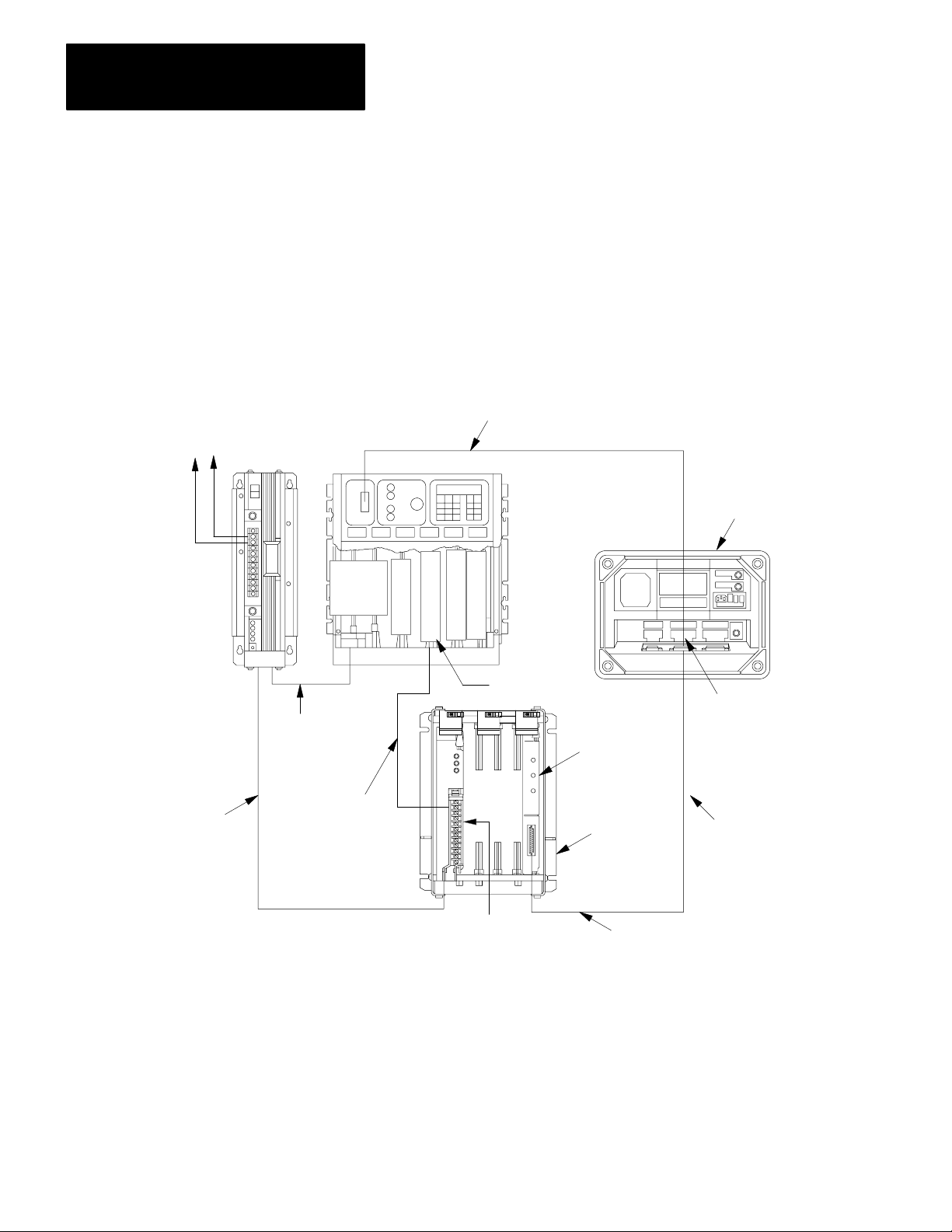
How to Connect Your Equipment
Connect your equipment with the appropriate cables (Figure 1.1 for
Mini-PLC-2/15 controllers, Figure 1.2 for PLC-2/20 or-2/30 controllers).
Be sure that the end of your IT/DH adapter cable labeled CHANNEL B is
connected to channel B on the industrial terminal.
23
Page 11
Chapter 2
Getting Started with Your ASCII Module
1771-P1
Power Supply
1771-CL
Power Cable
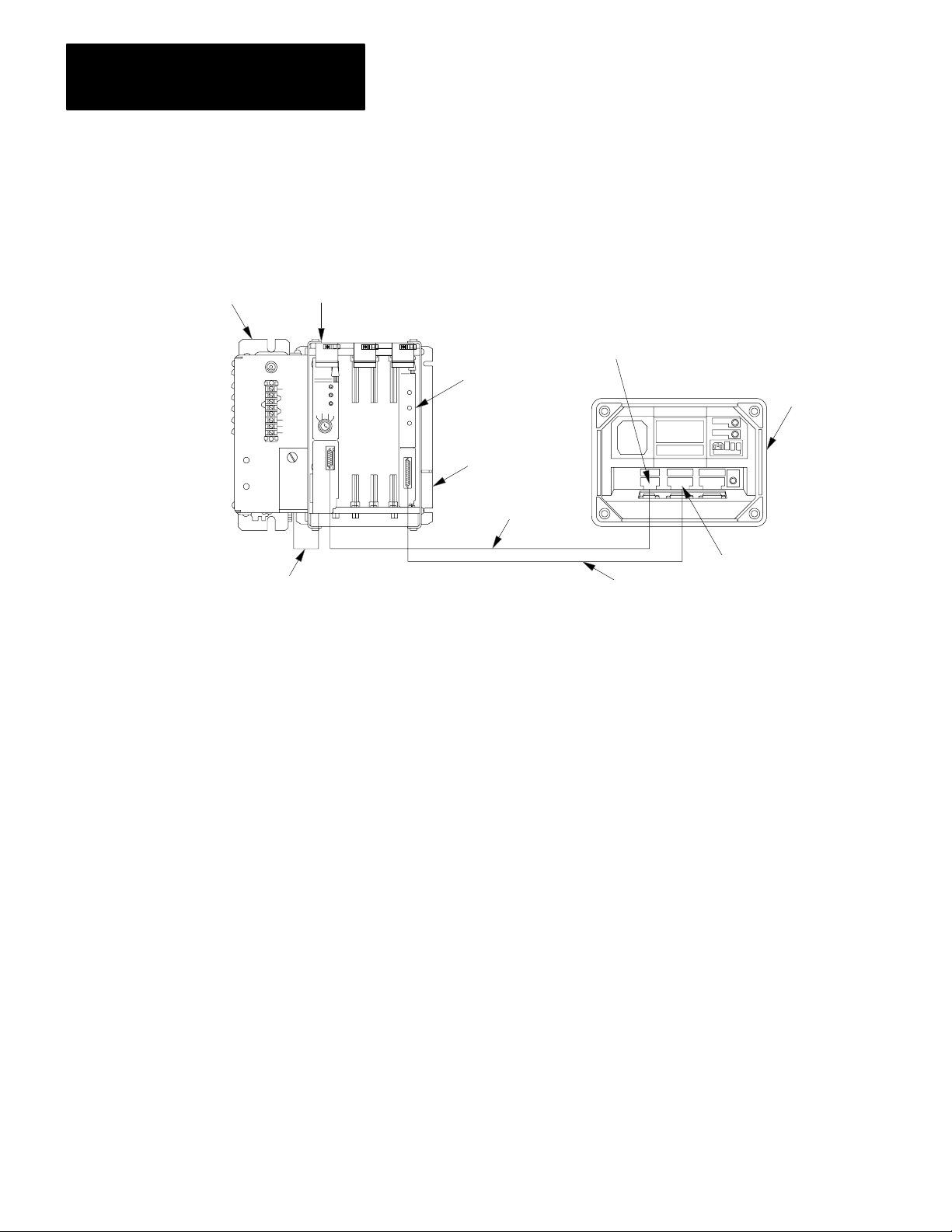
Figure 1.1
Connections
Mini-PLC-2/15
Processor
for MiniPLC2/l5 Controller
Module Group 1,
Slot 1
1771-DA ASCII
I/O Module
1771-A1, -A2, -A4
I/O Chassis
1772-TC
Processor Interface Cable
See WARNING in section titled How
to Connect Your Equipment." Using Channels
A & B
Channel A
1770-T3
Industrial Terminal
(rear view)
Channel B
1770-CB IT/DH
Adapter Cable
11817
1. Connect the power cable between the power supply and the I/O
chassis. The cable connects to the backplane of the I/O chassis
behind the processor/adapter slot.
2. Connect the processor interface cable between the PC processor and
channel A on the industrial terminal.
3. Connect the IT/DH adapter cable between the ASCII module and
channel B on the industrial terminal.
24
Page 12
Chapter 2
Getting Started with Your ASCII Module
1771-CK,-CJ
PowerCable
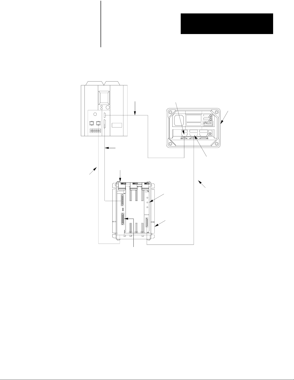
Figure 1.2
Connections
PLC-2/30
Processor
1771-ALLocal
AdapterModule
for PLC2/20 or PLC2/30 Controller
1772-TCProcessor
InterfaceCable
1771-CA,-CB
I/OInterconnect
Cable
ModuleGroup1,
Slot1
ChannelA
1771-DAASCII
I/OModule
See WARNING in section titled How
to Connect Your Equipment." Using Channels
A & B
1770-T3
IndustrialTerminal
(rearview)
ChannelB
1770-CBIT/DH
AdapterCable
1771-A1,-A2,-A4
I/OChassis
1777-CP
TerminationPlug
11818
4. (PLC-2/20, -2/30, only) Connect the I/O interconnect cable between
the PC processor and the I/O adapter module
If the IT/DH adapter cable is too short or not available, make your own.
It should not exceed 50 feet (Figure 1.4).
Using Channels A and B
You may or may not be able to connect cables to channels A and B at the
same time depending on the revision of your industrial terminal.
25
Page 13

Chapter 2
Getting Started with Your ASCII Module
Industrial terminals manufactured before May 1982 allow cross talk
between channels A and B. As a result, data table values could be altered.
Therefore, you should alternate cables between channels for the tutorials
of this manual when using these terminals. When using a series A
industrial terminal, you must alternate cables.
Your industrial terminal has a date code stamped in white on the upper
right corner of the rear label. If your industrial terminal (cat. no.
1770-T3/TA series B) is date coded T 8218 or earlier, or is not date coded,
alternate cables and observe the following warning:
WARNING: When cables are connect to channels A and B at
the same time, cross talk between these channels could cause
the processor to misread inputs and/or misapply outputs, with
possible damage to equipment and/or injury to personnel. For
this reason, do not remove the slide bar that prevents you from
connecting cables to channels A and B at the same time.
If your industrial terminal (cat. no. 1770-T3/TA series B) is date coded T
8219 or later, you can use channels A and B at the same time.
If alternating between channels A and B, connect the 1770-CB cable to
channel B when using the industrial terminal in alphanumeric mode as a
data terminal. Connect the 1772-TC cable to channel A when using the
industrial terminal in PLC-2 (ladder diagram) mode.
As an alternative, use a second industrial terminal in alphanumeric mode
on channel B, or use a Silent 700 data terminal. Connect either to the
1770-CB cable.
Checking ASCII Module Configuration
Your module is configured for RS-232-C operation when shipped from
the factory. If you suspect that its internal configuration (settings of
internal programing plugs) has been altered, you should check module
configuration (refer to section titled Choosing the Mode of
Communication in chapter 3). Do this as follows:
26
1. Remove covers from the module’s printed circuit board.
Page 14

Chapter 2
Getting Started with Your ASCII Module
2. Locate the programming plugs and set them according to RS-232-C
without control lines (figure 2.8).
Entering the ““Getting Started Program””
You may want to record on tape the ladder diagram of your application
program before proceeding because you will need to load ASCII logic
into a cleared memory for chapters 1 and 3.
Using your industrial terminal, enter the ““Getting Started Program””
(Figure 1.3) into processor memory. At this point, you do not need to
understand how the program works, but you should enter it exactly as
shown.
27
Page 15
Chapter 2
Getting Started with Your ASCII Module
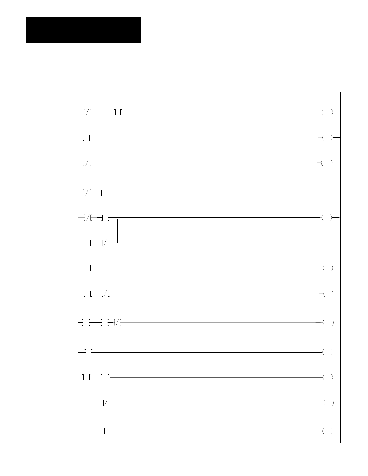
Figure 1.3
Getting
LADDER DIAGRAM DUMP
020
02
252
07
020
02
063
15
252
15
252
327
G
000
063
17
200
15
200
Started Program" (PLC2 Family)
START
200
PUT
000
200
07
063
TON
.01
PR 300
AC 000
035
00
15
15
03500252
15
03500252
15
251
063
G
000
020
063
G
000
02001252
02001252
=
100
01
247
=
200
16
16
020
00
200
L
OFF 15
200
U
OFF 15
020
01
020
L
OFF 00
020
U
OFF 00
200
L
ON 16
200
U
ON 16
28
Page 16

Chapter 2
Getting Started with Your ASCII Module
011
BLOCK XFER READ
DATA ADDR:
MODULE ADDR:
BLOCK LENGTH:
FILE:
BLOCK XFER WRITE
DATA ADDR:
MODULE ADDR:
BLOCK LENGTH:
FILE:
252 - 271
200 - 217
030
111
16
031
111
16
EN
17
111
DN
17
011
EN
16
111
DN
16
020
END 00460
NOTE: Configure the data table for two racks using [SEARCH][5][0]
before entering this program.
Installing Your ASCII Module
Be sure that power to the I/O chassis is turned off when installing (or
removing) your ASCII module as follows:
1. Remove power from the I/O chassis.
2. Insert the ASCII module in rack 1, module group 1, slot 1. The
program makes the processor communicate with the ASCII module
at that specific location. (If you must use another rack location and
are familiar with block transfer operation, change the rack, group,
and slot number of the module address in the block transfer read and
write instructions, accordingly.)
02
3. Turn on power to the I/O chassis. Three LED indicators on the
ASCII module illuminate momentarily. Their functions are:
FAULT: Normally off. This red LED indicator illuminates when the
module detects an internal fault.
29
Page 17

Chapter 2
Getting Started with Your ASCII Module
BUFFER FULL: Normally off. This yellow LED indicator
illuminates when the input buffer becomes full.
CHANNEL ACTIVE: This green LED indicator illuminates when
the industrial terminal is on, properly connected to the ASCII
module’s interface port, and set for alphanumeric mode.
Reading Data from Your ASCII
Device
In this demonstration, you will enter data and observe how it is stored in
the processor data table. You will use the industrial terminal in
alphanumeric mode as an ASCII data terminal when you enter data. Then
you will change the industrial terminal to PLC-2 mode and observe the
transferred data by displaying the contents of the block transfer read file.
You will use the following procedures:
In
Procedure
P1
P2
P3
P4
Set your industrial terminal to alphanumeric mode
Enter your data
Set your industrial terminal to PLC2 mode
See how data is stored in the data table
Y
ou W
ill
Later in this chapter and in chapter 3 you will combine these procedures
with others. The order in which you will perform them may vary.
Even if you are familiar with these procedures, we suggest that you read
them completely. If you deviate from them, proper operation may not
occur.
210
If you have not already done so, load the “Getting Started Program”
(Figure 1.3) into processor memory.
Procedure P1
Set Your Industrial Terminal to Alphanumeric Mode
1. Turn on the industrial terminal.
2. Insert the Alphanumeric Keytop Overlay (cat. no. 1770-KAA).
Page 18

Chapter 2
Getting Started with Your ASCII Module
To avoid switching keytop overlays every time you change the industrial
terminal operating mode, you can label numbers, letters, and [RETURN]
on the corresponding keytops of the PLC-2 family overlay.
3. Select alphanumeric mode.
Press 12 on the keyboard
The ASCII module’s CHANNEL ACTIVE LED illuminates.
4. Set the communication rate to 300 baud.
Press 13 [RETURN]
The cursor in the upper left corner of a blank screen tells you the terminal
is ready for your input.
5. Change the processor mode select switch to the RUN/PROG
position. (Failure to do this step now will prevent a transfer.)
Procedure P2
Enter Your Data
1. Be sure the processor mode select switch is in the RUN/PROG
position.
2. Enter data such as your first name followed by a couple of numbers.
Enter 11 characters including a space between your name and
numbers (Table 1.B).
211
Page 19

Chapter 2
Getting Started with Your ASCII Module
Table 1.B
Commonly
ASCII Hex ASCII Hex ASCII Hex
space 20
0 30
1 31
2 32
3 33
4 34
5 35
6 36
7 37
8 38
9 39
Used Data Characters
A 41
B 42
C 43
D 44
E 45
F 46
G 47
H 48
I 49
J 4A
K 4B
L 4C
M 4D
N 4E
O 4F
P 50
Q 51
R 52
S 53
T 54
U 55
V 56
W 57
X 58
Y 59
Z 5A
The industrial terminal displays the characters as you enter them. If
characters are not displayed, check the program that you loaded into
memory. If you find no errors, refer to Need Help? below.
3. Change the processor mode select switch to the PROG position.
(Failure to do this step now will prevent correct operation.)
Procedure P3
Set Your Industrial Terminal to PLC-2 Mode
1. Press [MODE SELECT]
2. Change the keytop overlay to PLC-2 family.
3. Select PLC-2 mode.
Press 11 on the keyboard
Procedure P4
See How Data Is Stored in the Data Table
1. Move the cursor to the rung containing the read block transfer
instruction (rung 14). The cursor will illuminate the instruction title
BLOCK XFER READ.
2. Display the contents of the read block transfer file in hex.
212
Page 20

Chapter 2
Getting Started with Your ASCII Module
Press [DISPLAY] 1
Results The industrial terminal displays the name and numbers (first 10
characters) that you entered in step 2. For example,
ALLEN 12345 would be displayed as:
POSITION FILE
001 E010
002 0000
003 414C
004 4C45
005 4E20 N
006 3132 1 2
007 3334 3 4
DA
TA
ASCII Equivalent
status word one
status word two
A L
L E
Entering the eleventh character caused the module to transfer the data.
Note the space entered between ALLEN and 12345.
The display of status word one (E010) and status word two (0000)
indicates normal status of the module.
3. Terminate this display by pressing [CANCEL COMMAND], and
return to ladder diagram.
Need Help?
If your display was all zeros, the data did not transfer. You may have
altered the procedure.
Did you enter your program exactly as shown?
Did the module’s CHANNEL ACTIVE LED go on?
Did you perform Procedure P1 before P2?
Did you perform Step 1 in Procedure P2?
Did you perform Step 3 in Procedure P2?
213
Page 21
Chapter 2
Getting Started with Your ASCII Module
If you are still having trouble, refer to “Testing the ASCII Module and
Cables,” to verify communication between the ASCII module and the
industrial terminal. If you suspect a cable problem, check the 1770-CB
cable (Figure 1.4).
Then try again, starting at Procedure P1.
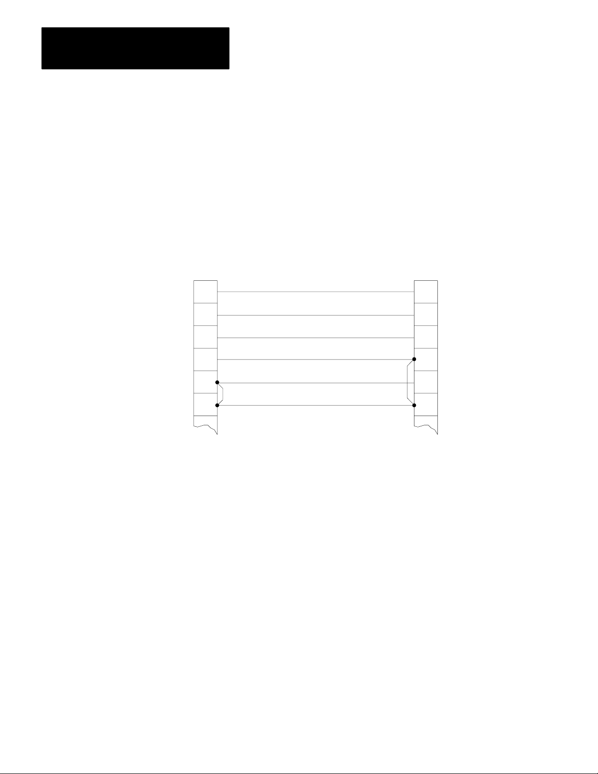
Figure 1.4
Minimum
Connections in the 1770CB Cable
1
2
3
7
18
25
ASCII Module
Interface Port
* Protective Ground
Transmitted Data
Received Data
Ground
1
2
3
7
18
25
Industrial Terminal
Channel B
Connectors:
25pin DShell
Male Connector
Cable Kit
1770XXP (each
end)
Cable:
Belden 8723 or
equivalent
* In cable but not
required for ASCII
module
11819
Writing Data to Your ASCII
Device
214
In this demonstration, you will load data characters into the write block
transfer file and observe how they are displayed. You will use the
industrial terminal in PLC-2 mode to load data. Then you will change the
industrial terminal to alphanumeric mode and observe the transferred data.
Page 22

Chapter 2
Getting Started with Your ASCII Module
You will use the following procedures where Procedures P1 and P3 are
repeated from the section titled Reading Data from Your ASCII Device.
In
Procedure
Y
ou W
ill
P3
P5
P1
Set your industrial terminal to PLC2 mode
Load data into the write block transfer file
Set your industrial terminal to alphanumeric mode (and
observe the transferred data)
Procedure P3
Set Your Industrial Terminal to PLC-2 Mode
NOTE: Skip this procedure if your processor is already in PLC-2 mode.
1. Press [MODE SELECT]
2. Check that the PLC-2 family keytop overlay is in place.
3. Select PLC-2 mode.
Press 11 on the keyboard
The beginning of your ladder diagram program will be displayed.
Procedure P5
Load Data into an Instruction File
1. Check that the processor mode select switch is in the PROG position.
2. Move the cursor to the instruction whose file you want to load
(BLOCK XFER WRITE).
3. Display the file in hex.
Press [DISPLAY] 1
4. Load new data starting in position 003 for a write block transfer
instruction, position 001 for other file instructions. (Positions 001
and 002 are reserved for command words in a write block transfer
instruction.)
215
Page 23

Chapter 2
Getting Started with Your ASCII Module
For example, load the following hex codes that are equivalent to
BRADLEY 12345 as follows: (Note the space between BRADLEY and
12345.)
POSITION FILE
003 4252 B R
004 4144 A D
005 4C45
006 5920 Y
007 3132 1 2
008 3334 3 4
009 3500 5
DA
TA
ASCII Equivalent
L E
Check your display of FILE DATA to be sure that you entered all data
exactly as shown.
Don’t forget to press [INSERT][
] after entering data in each position.
Use the shift key to enter the hex character C.
Procedure P1
Set Your Industrial Terminal to Alphanumeric Mode
216
1. Insert the alphanumeric keytop overlay.
2. Select alphanumeric mode.
Press [MODE SELECT] 12
3. Set the communication rate to 300 baud.
Press 13 [RETURN]
The module’s CHANNEL ACTIVE LED turns on.
4. Change the processor mode select switch to the RUN/PROG
position.
Page 24

Chapter 2
Getting Started with Your ASCII Module
Results The following display appears at the upper left corner of the
industrial terminal:
BRADLEY 12345
5. Terminate the display and return to ladder diagram. Use the PLC-2
family keytop overlay.
Press [MODE SELECT] 11
Summary
Now that you have demonstrated the transfer of data from your ASCII
device to the data table and vice versa, you are ready to use these
procedures further. First, read the next chapter, “Choosing Module
Features.” It defines key words and concepts. Then in chapter 3, “ASCII
Tutorial”, you will use these procedures to demonstrate operating
characteristics of your module.
217
Page 25

Chapter 2
Getting Started with Your ASCII Module
PLC3 Processors
What You Need To Get Started
You will demonstrate the operation of your ASCII module by reading data
from the industrial terminal to the processor data table, and by writing
data from the data table to the industrial terminal. You will use your
industrial terminal as an ASCII device for entering data (read), and for
displaying data (write).
You will set up a test I/O chassis with a PC processor, power supply,
industrial terminal, cables, and your ASCII module. You will need about
an hour to complete the procedures in this chapter and about two hours to
complete the procedures in chapter 3.
You may want to record your application ladder diagram program before
proceeding because you will need to load ASCII logic into a cleared
memory for tutorial chapters 1 and 3 in this manual.
Equipment That You Need
You will need the following equipment (Table 1.C) using your existing
system and/or spare equipment.
218
Page 26

Chapter 2
Getting Started with Your ASCII Module
Table 1.C
Equipment
PLC3 Main Chassis
Main Processor Module
I/O ScannerProgrammer Interface Module
Memory Module
Power Supply
Industrial T
PLC3 Keytop Overlay
I/O Chassis
Remote I/O Adapter Module
ASCII i/O Module
T
winaxial I/O Interface Cable
IT/DH Adapter Cable
PLC3 Industrial T
Chassis Power Cable
I/O Power Cable
Terminators
[1]
[2]
(PLC3)
Equipment
erminal
erminal Cable
Supplied with the Industrial T
Supplied with the PLC3 Main Chassis
erminal
Catalog Number
1775A1
1775L1,L2
1775S4A
1775MR
1775P1
1770T4
1770KDA
1771Al,A2,A4
1771AS
1771DA
1770CD
1770CB
1775CAT
1775CAP
1775CH
1775XT
[1]
[2]
If you use an existing system, place the ASCII module in a chassis on a
separate channel. Use a spare scanner module (cat. no. 1775-S4A,-S4B)
if necessary.
The ASCII module draws 1.3A from the backplane. If you place the
module in a chassis containing other modules, be sure that the total
current drain of all modules in the chassis does not exceed the maximum
for the backplane and power supply.
219
Page 27
Chapter 2
Getting Started with Your ASCII Module
How to Connect Your Equipment
Connect your equipment using the appropriate cables (Figure 1.5).
120V AC
L2
L1
1775-P1
Power Supply
1775-CAP
Chassis
Power Cable
Figure 1.5
Connections
UNIT
(CPU)
RAM
G
CENTRAL
PROCESSIN
for PLC3 Controller
1775-CAT
Industrial Terminal Cable
O
I/O
S
M
C
E
A
M
N
O
N
R
E
Y
R
O
P
P
T
T
I
I
O
O
N
N
A
A
L
L
1775-S4A
Scanner
PLC-3
Processor Chassis
1771-DA ASCII
I/O Module
1771-T4
Industrial Terminal
(rear view)
Channel B
Change Cables
as required
220
1771-CH
I/O Power
Cable
1770-CD
Twinaxial Cable,
10,000 ft. Max.
total each
I/O Channel
1771-AS Romote
I/O Adapter Module
1771-A1, -A2, -A4
I/O Chassis
1772-TC
Processor Interface Cable
1770-CB IT/DH
Adapter Cable
1. Connect the chassis power cable between the power supply and the
processor chassis.
11820
Page 28
Chapter 2
Getting Started with Your ASCII Module
2. Connect the I/O power cable between the power supply and the I/O
chassis.
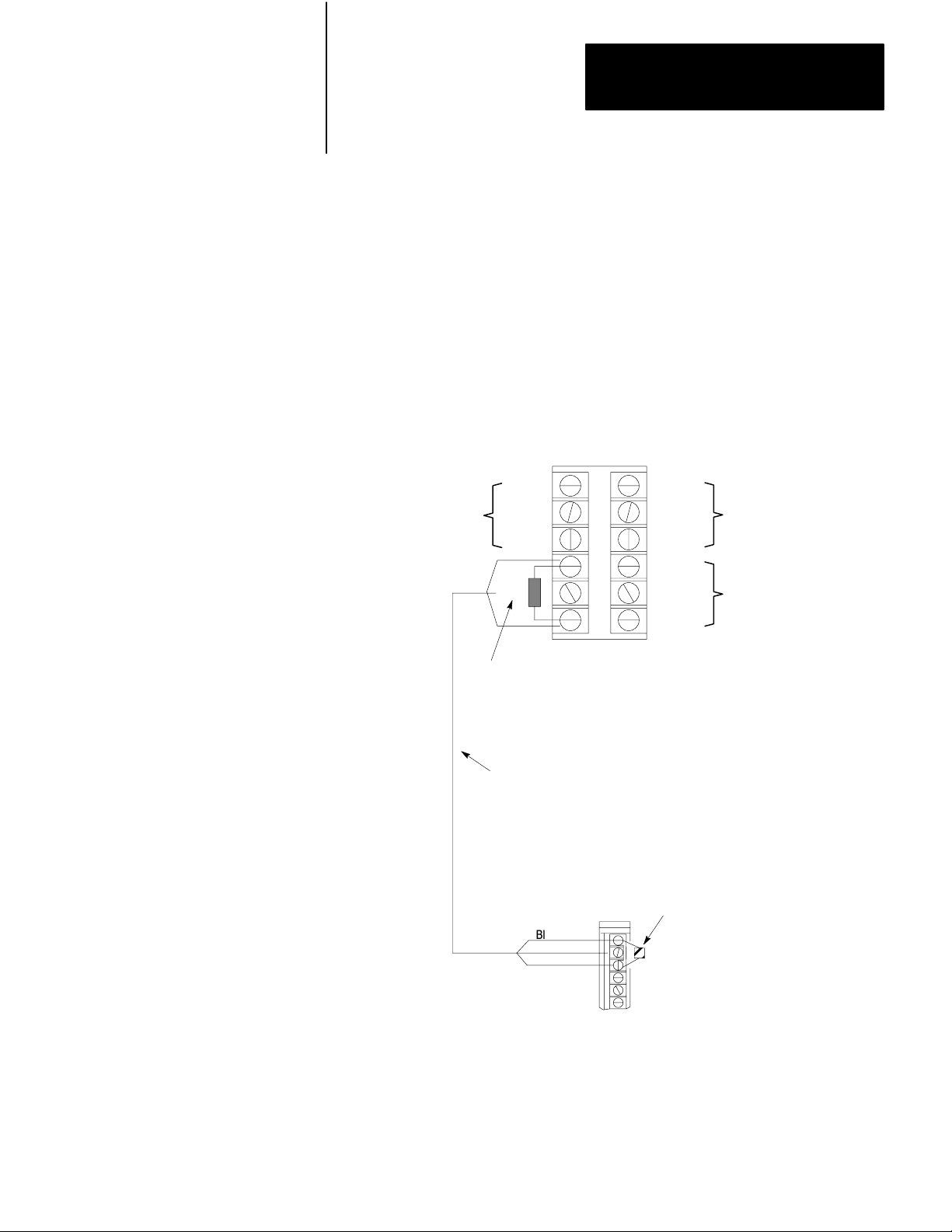
3. Connect the twin axial cable between the I/O scanner in the
processor chassis and the remote I/O adapter module in the I/O
chassis (Figure 1.6).
Figure 1.6
Twinaxial
Cable T
erminations
Terminals on I/O Scanner Module
Channel
No. 3
Channel
No. 1
Line 1
Shield
Line 2
Blue
Shield
Clear
Line 2
Terminator Resistor
(Cat. No. 1770-XS or 1770-XT)
150 ohm 0.5 W
1770CD Twinaxial Cable
Terminals on field Wiring Arm
of 1770-AS Adapter Module
Blue
Shield
Clear
Line 1
Shield
Line 2
Line 1
Shield
Line 2
Terminator Resistor
(Cat. No. 1770-XT)
150 ohm 0.5 W
Channel
No. 4
Channel
No. 2
Absence of a terminator resistor can cause block
NOTE:
transfer errors
4. Connect the industrial terminal cable between channel B of the
industrial terminal and the processor chassis.
11821
221
Page 29
Chapter 2
Getting Started with Your ASCII Module
5. Connect the IT/DH adapter cable between the ASCII module and
Channel B
Periodically you will have to switch the cables that connect to channel B
of the industrial terminal.
channel B of the industrial terminal.
You will use the industrial terminal cable (cat. no. 1775-CAT) when
using the industrial terminal in PLC-3 mode and entering or displaying
data in the PLC-3 data table.
You will use the IT/DH adapter cable (cat. no. 1770-CB) when using
the industrial terminal in alphanumeric mode as an ASCII device
connected to your ASCII module.
Be sure to observe the labels on the cable connectors and connect each
to its designated port.
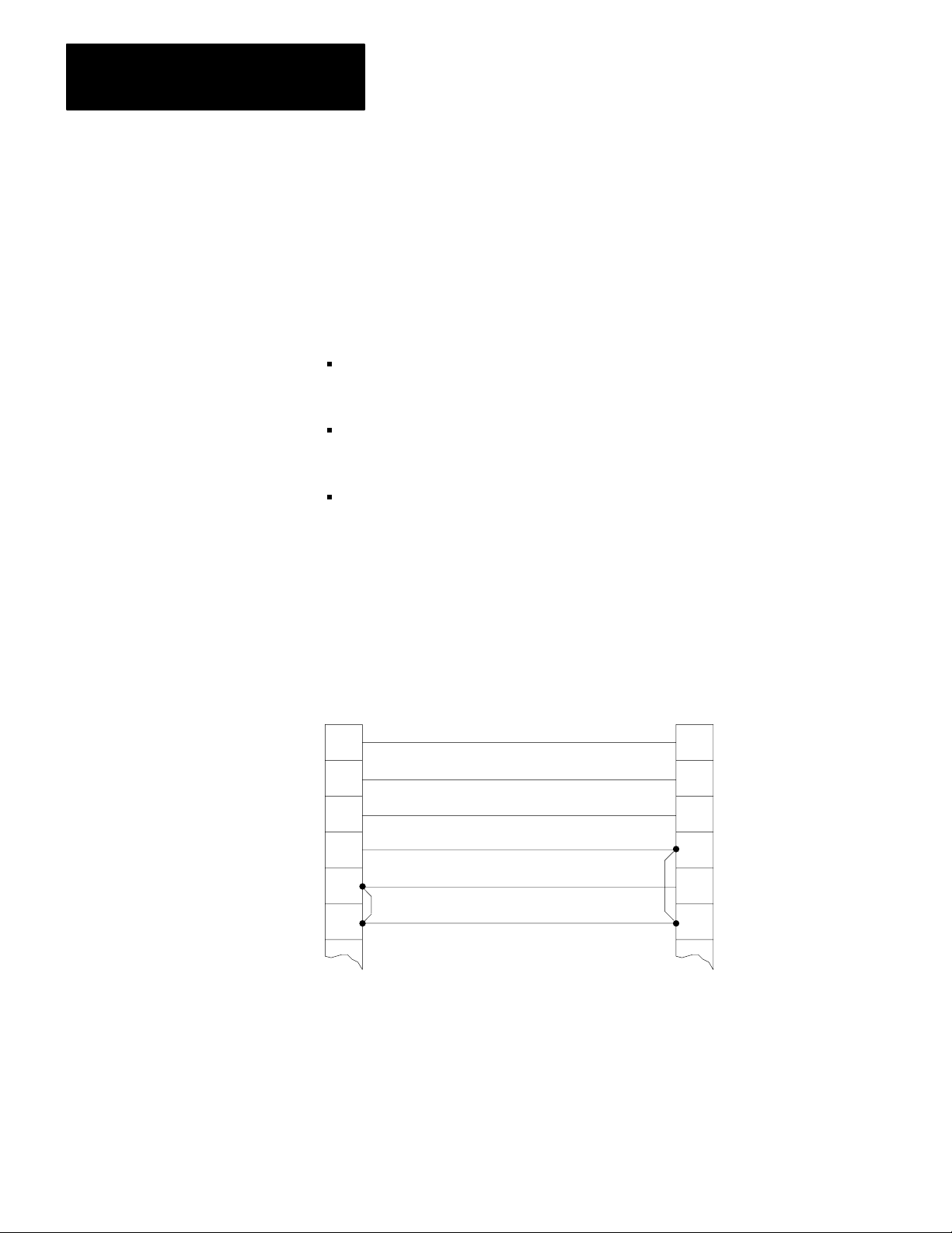
Also, if the IT/DH adapter cable is too short or not available, make your
own. It should not exceed 50 feet (Figure 1.7).
Figure 1.7
Minimum
18
25
ASCII Module
Interface Port
Connections in the 1770CB Cable
1
2
3
7
* Protective Ground
Transmitted Data
Received Data
Ground
1
2
3
7
18
25
Industrial Terminal
Channel B
Connectors:
25pin DShell
Male Connector
Cable Kit
1770XXP (each
end)
Cable:
Belden 8723 or
equivalent
* In cable but not
required for ASCII
module
222
11819
Page 30

Chapter 2
Getting Started with Your ASCII Module
Refer to your PLC-3 Programmable Controller Installation and Operation
Manual (publication 1775-800) for additional installation information
such as switch settings for the adapter module and I/O chassis, and for
grounding information.
Checking ASCII Module Configuration
Your module is configured for RS-232-C operation when shipped from
the factory. If you suspect that its internal configuration (settings of
internal programming plugs) has been altered, you should check module
configuration (refer to section titled ”Choosing the Mode of
Communication,” in chapter 2). Do this as follows:
1. Remove the covers from the module’s printed circuit board.
2. Locate the programming plugs, and set them according to RS-232-C
without control lines (Figure 2.8).
Entering the Getting Started Program"
Using your industrial terminal, enter the “Getting Started Program”
(Figure 1.8) into processor memory. At this point, you do not need to
understand how the program works, but you should enter it exactly as
shown.
223
Page 31

Chapter 2
Getting Started with Your ASCII Module
Figure 1.8
Getting
I0001
00
WO005:0000
00
WO003:0000
07
WO003:000015WO002:0000
WO003:000015WO002:0000
WO005:000002WO003:0000
WO005:000002WO003:0000
Started Program" (PLC3)
15
15
15
15
RUNG NUMBER RM0
RUNG NUMBER RM1
RUNG NUMBER RM2
RUNG NUMBER RM3
RUNG NUMBER RM4
MOV
MOVE FROM A TO R
A : WO001:0000
0000000000000000
R : WO002:0000
0000000000000000
WO002:0000
07
WO005:0000
02
WO002:0000
L
15
WO002:0000
U
15
224
I0001
02
I000102WO005:0000
03
WO005:0000
04
WO005:000004WO003:0000
16
WO005:000004WO003:0000
16
RUNG NUMBER RM5
RUNG NUMBER RM6
RUNG NUMBER RM7
RUNG NUMBER RM8
RUNG NUMBER RM9
WO005:0000
U
03
WO005:0000
04
WO005:0000
L
03
WO002:0000
L
16
WO002:0000
U
16
Page 32

Chapter 2
Getting Started with Your ASCII Module
RUNG NUMBER RM10
001
1
0
001
1
0
CNTL
EN
12
CNTL
DN
15
CNTL
EN
13
CNTL
EN
02
CNTL
DN
05
CNTL
ER
03
WO005:0000
00
WB004:0000
15
WB004:0000
05
WB004:0000
17
RUNG NUMBER RM11
BTR
BLOCK XFER READ
RACK :
GROUP :
MODULE :
DATA :
LENGTH =
CNTL :
BTW
BLOCK XFER WRITE
RACK :
GROUP :
MODULE :
DATA :
LENGTH =
CNTL :
1=HIGH
FO003:0000
FB004:0000
1=HIGH
FO002:0000
FB004:0000
1. Connect the 1775-CAT cable to channel B of the industrial terminal.
2. Turn on power to the I/O chassis and PLC-3 controller.
3. Turn off the memory protect switch on the front panel of the PLC-3
controller.
4. Select program load mode on the PLC-3 front panel.
Press [SHIFT][LIST] 3 [ENTER]
5. Turn on the industrial terminal. It should automatically display
ladder diagram mode. If not,
Press [SHIFT][MODE]1
6. Enter the following key sequence on the industrial terminal keyboard
before entering your program.
Press[INSERT][SHIFT][RUNG][ENTER]
225
Page 33

Chapter 2
Getting Started with Your ASCII Module
The displayed power bars will be replaced by I’s at the left and right
margins of the screen. The prompt EDITING will blink.
7. Enter your instructions and addresses. Refer to the PLC-3
NOTE: Be sure that you have entered the prefix F (file) in the addresses
of your block transfer read (BTR) and block transfer write (BTW)
instructions. Create a (nominal) 64 word file for your BTR and BTW data
files as follows:
where the <> symbols are not entered but designate data that you enter.
Example file addresses are O3:0 and O2:0.
Programming Manual (publication 1775-801) as needed.
Press CR,<file address>100,Y [ENTER]
8. Assemble your program.
Press ASM,Y[ENTER]
The power bars now become solid lines.
9. Check your program using the consecutive display mode starting
with the first rung.
Press [SHIFT][DISPLAY][ENTER]SR[ENTER]
Use [RUNG
↓] and [RUNG ↑] as needed to move from rung to rung.
Installing Your ASCII Module
Be sure that power to the I/O chassis is turned off when installing (or
removing) your ASCII module as follows:
1. Turn off power to the I/O chassis.
226
2. Insert the ASCII module in rack 1, module group 1, slot 1. The
program makes the processor communicate with the ASCII module
at that specific location. (If you must use another rack location and
are familiar with programming block transfer instructions, change
Page 34

Chapter 2
Getting Started with Your ASCII Module
the rack, group, and slot number of the module address in the block
transfer read and write instructions, accordingly.)
3. Turn on power to the I/O chassis. Three LED indicators on the
ASCII module illuminate momentarily. Their functions are:
FAULT: Normally off. This red LED indicator illuminates when the
module detects an internal fault.
BUFFER FULL: Normally off. This yellow LED indicator illuminates
when the input buffer becomes full.
CHANNEL ACTIVE: This green LED indicator illuminates when the
industrial terminal is on, properly connected to the ASCII module’s
interface port, and set for alphanumeric mode.
227
Page 35

Chapter 2
Getting Started with Your ASCII Module
Reading Data from Your ASCII
Device
In this demonstration you will enter data and observe how it is stored in
the processor data table. You will use the industrial terminal in
alphanumeric mode as an ASCII data terminal when you enter data. Then
you will change the industrial terminal to PLC-3 mode and observe the
transferred data by displaying the contents of the block transfer read file.
You must alternate cables that connect to channel B of the industrial
terminal, one cable for alphanumeric mode, the other for PLC-3 mode.
You will simulate the action of an input bit through the PLC-3 front panel
to enable a write block transfer.
You will use the following procedures.
In
Procedure
P1
P2
P3
P4
Connect the 1770CB cable, and set your industrial
terminal to alphanumeric mode
Enter your data
Connect the 1775CA
terminal to PLC3 mode
See how data is stored in the data table
Y
ou W
ill
T cable, and set your industrial
Even if you are familiar with these procedures, read them completely. If
you deviate from these procedures, proper operation may not occur.
If you have not already done so, load the “Getting Started Program”
(Figure 2.8) into processor memory.
Procedure 1
Set Your Industrial Terminal to Alphanumeric Mode
1. Turn on the industrial terminal.
2. Connect the 1770-CB cable to channel B of the industrial terminal.
3. Select alphanumeric mode.
Press [SHIFT][MODE] 2
The CHANNEL ACTIVE LED on the module illuminates.
228
Page 36

Chapter 2
Getting Started with Your ASCII Module
4. Set operating parameters:
Communication rate to 300 baud. Press A (as needed) until the
communication rate, as displayed on the screen, reaches 300 baud.
Hardware handshaking to ON. Press D
DUPLEX to FULL. Press F
B and C to any setting.
E, and G thru M to OFF.
Press [ENTER] to load parameters.
The prompt, ENTERING ALPHANUMERIC TERMINAL MODE, tells
you the terminal is ready for your input.
Procedure P2
Enter Your Data
1. Check that the PLC-3 controller is operating in run monitor. Use the
PLC-3 front panel.
Press [SHIFT][LIST] 2 [ENTER]
2. Enter data, such as your first name, followed by a couple of numbers.
Enter 11 characters counting the space between your name and
numbers. Select the characters from commonly used data characters
(Table 1.D).
Table 1.D
Commonly
Used Data Characters
ASCII Hex ASCII Hex ASCII Hex
space 20 A 41 N 4E
0 30 B 42 O 4F
1 31 C 43 P 50
2 32 D 44 Q 51
3 33 E 45 R 52
4 34 F 46 S 53
5 35 G 47 T 54
6 36 H 48 U 55
7 37 I 49 V 56
229
Page 37

Chapter 2
Getting Started with Your ASCII Module
The industrial terminal displays the characters as you enter them. If
characters are not displayed, check the program that you loaded into
memory. Check step 3, operating parameters, for errors. If you find no
errors, refer to Need Help? below.
Procedure P3
Set Your Industrial Terminal to PLC-3 Mode
ASCII HexASCIIHexASCIIHex
8 38 J 4A W 57
9 39 K 4B X 58
L 4C Y 59
M 4D Z 5A
1. Connect the 1775-CAT cable to channel B.
2. Display your ladder diagram.
Press [SHIFT][MODE]1
Procedure P4
See How Data Is Stored in the Data Table
1. Display the block transfer read file. Enter the address of that file
(O3:0) with the following key sequence.
Press DD,O3:0, [SHIFT]%A [ENTER]
Results The name and numbers (11 characters or more) that you entered
are displayed. For example, if you had entered
ASCII 7890123
230
the space between ASCII and 78790123 would count as an entered
character, and your display would show 10 characters as follows:
RADIX
= %A START = W
WORD #
00000 E0H11H 00H00H ASCII 789000H00H
0 1 2 3 4 5 6 7
A011:0248
Page 38

Chapter 2
Getting Started with Your ASCII Module
2. Display the same file in hex.
Press,%H [ENTER]
The following display appears:
RADIX
= %A START = W
WORD #
00000 E011 0000 4153 4349 4920 3738 3930 0000
0 1 2 3 4 5 6 7
A011:0248
3. You can display the file in other number bases by replacing the H in
step 2 with D for decimal, B for binary, or A for ASCII.
Compare the following displays.
Number
Base
ASCII (A)
Hex (H)
Decimal (D)
Display
A S C I I 7 8 9 0 00H00H
41 53 43 49 49 20 37 38 39 30 0000
41 53 43 49 49 20 37 38 39 30 000
Zero V
alue
Results Entering the eleventh character caused the module to transfer the
data.
Status word one (E011) and status word two (0000) indicate normal
operation of the module. These are shown in display words 0 and 1,
respectively.
4. Terminate this display and return to ladder diagram.
Press [SHIFT][MODE]1
Need Help?
If your display was all zeros (00H00H), ASCII display), the data did not
transfer. You may have altered the procedure.
Did you enter your program exactly as shown?
Did the module’s CHANNEL ACTIVE LED go on?
Did the CHANNEL 1 LED on your scanner go on?
Did the ACTIVE LED on your adapter go on?
Have you configured your PLC-3 controller (LIST function)?
231
Page 39

Chapter 2
Getting Started with Your ASCII Module
If you are still having trouble, refer to “Testing the ASCII Module and
Cables,” to verify communication between the ASCII module and the
industrial terminal. If you suspect a cable problem, check the 1770-CB
cable (Figure 1.7).
Then try again starting with Procedure P1.
Writing Data to Your ASCII
Device
In this demonstration you will load data characters into the write block
transfer file and observe how they are displayed by the industrial terminal.
You will use the industrial terminal in PLC-3 mode to load data. Then
you will change the industrial terminal to alphanumeric mode and observe
the transferred data.
The procedures that you will follow are described below.
In
Procedure
P3 Connect
P5 Load
P1 Connect
P6
the 1775CA
mode
data into the file
the 1770CB cable, and set your industrial terminal to alphanu
mode
meric
Enable the transfer of new data
T cable, and set your industrial terminal to PLC3
Y
ou W
ill
Procedure P3
Set Your Industrial Terminal to PLC-3 Mode
232
NOTE: Skip this procedure if the industrial terminal is already in PLC-3
mode.
1. Connect the 1770-CAT cable to channel B.
2. Set your industrial terminal to PLC-3 mode, and display the
beginning of your ladder diagram program.
Press [SHIFT][MODE]1
Procedure P5
Load Data into a File
1. Place the processor in program load mode using the PLC-3 front
panel.
Page 40

Chapter 2
Getting Started with Your ASCII Module
Press [SHIFT][LIST]3[ENTER]
2. Display the file that you want to load by entering the address of that
file (O2:0) with the following key sequence.
Press DD,O2:0,[SHIFT]%A[ENTER]
3. Load ASCII data into the file starting with the third word (display
word 2) for block transfer instructions (the first word for file move
instructions). The first and second words of a write block transfer
instruction are reserved for command words (handshaking). Press
[ENTER] and [ ] after loading each word.
For example, if you load the following:
BRADLEY 1234
Your file will appear as
RADIX
= %A START = W
WORD #
00000 60H00H 00H00H BRADLE Y 123 4
0 1 2 3 4 5 6 7
A011:0248
4. Change the display to hex and observe how the equivalent data is
displayed.
Press,[SHIFT]%H[ENTER]
Your file display will change to the following:
RADIX
= %A START = W
WORD #
00000 E011 0000 4252 4144 4C45 5920 3132 3334
0 1 2 3 4 5 6 7
A011:0248
Check the display of data to be sure that you entered all data exactly as
shown.
Procedure P1
Set Your Industrial Terminal to Alphanumeric Mode
233
Page 41

Chapter 2
Getting Started with Your ASCII Module
1. Connect the 1770-CB cable to channel B.
2. Select alphanumeric mode.
3. Check operating parameters:
Press [SHIFT][MODE]2
Communication rate is 300 baud.
Hardware handshaking is ON.
DUPLEX is FULL.
B and C are any setting.
E, and G thru M are OFF.
Press [ENTER] to load parameters.
The module’s CHANNEL ACTIVE LED turns on.
4. Change the operation of your PC-3 controller to run monitor from
the PLC-3 front panel.
Press [SHIFT][LIST]2[ENTER]
Procedures P6
Enable the Transfer of New Data
1. Set bit I001/02 to enable program logic (the write block transfer
handshaking) using the PLC-3 front panel.
Press [CLEAR][SHIFT]I0[SHIFT][BIT]1[BIT]2
[DISPLAY]
The front panel displays the bit address with an asterisk showing its
status, 1 or 0.
234
I000:0001/02*0
2. Set the bit using the PLC-3 front panel.
Press 1 [ENTER]
Results The industrial terminal displays
Page 42

Chapter 2
Getting Started with Your ASCII Module
BRADLEY 12345
at the upper left corner of the screen.
3. Reset the bit using the PLC-3 front panel.
Press 0 [ENTER]
4. Terminate the display and return to ladder diagram by connecting the
1770-CB cable to channel B, and entering the following keystrokes
on the industrial terminal keyboard.
Press [SHIFT][MODE]1
Summary
Now that you have demonstrated how data is transferred from your ASCII
device to the data table and vice versa, you are ready to use these
procedures further. Next, read “Choosing Module Features,” Chapter 2.
It will define key words and concepts. Then, in Chapter 3, “ASCII
Tutorial,” you will use these procedures to demonstrate operating
characteristics of your module.
235
Page 43

Chapter
Choosing Module Features
3
Chapter Objectives
Choosing the Mode of
Communication
Because of the many types of ASCII devices available and the variety of
possible applications, you must configure your module according to the
ASCII device and specific application that you have chosen. To do this,
you must make some decisions. We will show you how to configure your
module using programming plugs and by setting bits in initialization
words.
Following the description of each module feature, we will show you how
to record your decision whether to use the feature, and when appropriate,
the quantity pertaining to the feature. At the end of this chapter, you will
consolidate your decisions on a worksheet. You can use the worksheet to
configure your module for your specific ASCII device and application.
This manual uses the following notation when referring to initialization
words and bits. There are four initialization words to configure your
module: IW1, IW2, IW3, and IW4. Bits within an initialization word are
shown in parentheses after the word. For example, bits 10 thru 17 in
initialization word three would appear as IW3(10-17).
The ASCII module responds to three modes of communication.
RS-232-C
Current Loop, 20mA
A-B Long Line
RS232C
Use this mode for communicating up to approximately 50 cable feet
between a printer or CRT and the ASCII module. The Electronics
Industry Association (EIA) standard RS-232-C sets data and control line
voltage levels for serial data communication. Data transmission is
negative true logic: -5 to -15Vdc for a logic 1, +5 to +15Vdc for a logic 0.
Control line commands are positive true logic: +5 to +15Vdc for enable,
-5 to -15Vdc for inhibit. The standard also specifies a 25-pin connector
and defines pin functions. Most systems use only the following pins:
31
Page 44

Chapter 3
Choosing Module Features
Pin Signal
2
transmit
data
receive data
3
request to send
4
clear to send
5
ground
7
Refer to Table 2.A for a detailed listing of RS-232-C pin functions.
Table 2.A
RS232C
Pin
No
2 T
3
4
5
6
7
8
Connector Pin Functions
Signal Name
ransmitted Data
Received Data
Request to Send
Clear to Send
Data Set Ready
Signal Ground
Receive Line Signal
Detector
EIA
Circuit
BA DTE
BB 1771DA
CA DTE T
CB 1771DA
CC 1771DA
AB
CF 1771DA
Source Functions
(DCE)
(DCE)
(DCE)
(DCE)
Data T
ransfer to
1771DA (DCE)
Data T
ransfer to DTE
ells the 1771DA data is
transmitted.
T
ells DTE that data is
transmitted. Enabled only
if pin 4 is Vdc (of
T
ells DTE that 1771DA
(DCE) is ready
Common ground for all
signals thru interface port
on 1771DA.
T
ied to +12V dc
f).
.
32
20
Data T
erminal Ready
CD DTE T
ells 1771DA (DCE) that
DTE is ready
+V dc to send or receive.
. Must be
Current Loop
Use the current loop for communicating up to approximately 500 cable
feet between your ASCII device and ASCII module. A current loop has
high immunity to errors caused by electrical noise, has no signal
attenuation, eliminates ground loops, and is low cost.
A current loop is a loop that carries current (generally 20mA) between
electronic equipment by means of a twisted pair of wires. A transmitting
device in the loop transmits digital signals by interrupting the current
Page 45

Chapter 3
Choosing Module Features
flow. A receiving device in the loop senses the interruptions. By
convention, a logic 1 corresponds to the presence of loop current; a logic
0 corresponds to the absence of loop current.
A current loop transmitter or receiver can be either of two types: active
(source) or passive (sink). An active transmitter supplies current to the
loop. Any receivers or other transmitters within that loop must be passive
units that accept the supplied loop current. Alternately, an active receiver
supplies current to passive transmitters or other passive receivers in the
loop.
Current sources that power a current loop vary in complexity. The
simplest is a resistor and voltage source. More complex current sources
contain active elements or integrated circuits to provide constant current
under various power supply and load conditions.
Refer to Table 2.B and Table 2.C for a detailed listing of current loop pin
functions.
Pin No.
11
12
18
24
Pin No.
11
Table 2.B
Current
Passive Receive/Passive T
Signal Name
Module T
Module Receiver Circuit
Module T
Module Receiver Circuit Return
Module T
Control and Return
ransmitter Circuit
ransmitter Circuit Return
Table 2.C
Current Loop Connector Pin Functions
Passive Receive/Active T
Signal Name
ransmitter
, Circuit
Loop Connector Pin Functions
ransmit
Source Function
Peripheral or Power Supply Controls current loop, allowing
Peripheral Device
ransmit
Source Function
peripheral device to read data
Completes current loop, allowing
transfer of data to 1771DA
Return for module transmitter circuit
Return for module receiver circuit
Controls current loop, allowing
peripheral device to read data. Serves
as return for transmitter circuit.
12
13
24
Module Receiver Circuit
Module T
Module Receiver Circuit Return
ransmitter Circuit Source
Peripheral Device
1771DA
Completes current loop, allowing
transfer of data to 1771DA
Supplies current for current loop
interface
Return for module receiver circuit
33
Page 46

Chapter 3
Choosing Module Features
AB Long Line
Use A-B Long Line for communicating up to 5000 cable feet between an
industrial terminal, serving as an ASCII device, and the ASCII module.
Refer to Table 2.D for a detailed listing of A-B Long Line pin functions.
Table 2.D
AB
Long Line Connector Pin Functions
Pin No.
2 T
7 T
11
25
Signal Name
ransmitted Data
ransmitted Data Return Return for transmitted data
Received Data
Received Data Return
AB Long Line Device
1771DA
Source Function
Data T
ransfer to 1771DA
Data transfer to AB Long Line Device
Return for received data
Selecting the Communication Mode
The communication mode that you choose depends on the cable distance
from your ASCII device to your ASCII module, and on characteristics of
your ASCII device (Table 2.E).
Table 2.E
of Communication
Mode
If Distance is
Less Than
50 feet
And Y
our ASCII Device is a
Data T
erminal Equipment (DTE) and conforms
to RS232C
without control lines
with control lines
Then Choose this
T
ransmission Mode
RS232C (Figure 2.1)
4wire cable
8wire cable
34
Data Set (modem) and conforms to RS232C
without control lines
with control lines
500 feet
5000 feet AB industrial terminal or contains a line driver
DTE and provides a 20mA current source for
the transmit line, only
DTE and requires a 20mA external current
source for its transmit line
DTE and provides 20mA current sources for
transmit and receive lines
receiver for AB long line operation.
RS232C (Figure 2.2)
4wire cable
8wire cable
Current Loop (Figure 2.3)
The module powers its own transmit line.
Current Loop (Figure 2.4)
Y
ou add the power supply for the DTE.
Current Loop (Figure 2.5)
The module operates in passive transmit.
AB Long Line (Figure 2.6)
Page 47

Chapter 3
Choosing Module Features
The functions of the cable conductors (Figure 2.1 thru Figure 2.7) are
referenced to your ASCII device, not to your ASCII module.
Figure 2.1
RS232C
Connections (50 ft. max): Data T
erminal to Data Set
(Refer to specifications in Appendix D)
Device
Data Terminal
Equipment (DTE)
Drain Wire (Shield)
2
Transmit
7
Receive
3
4
Transmitted Data (BA)
Signal Ground (AB)
Received Data (BB)
Request to Send (CA)
ASCII Module
Data Set (DCE)
2
7
3
4
To I/O
Chassis
Ground
Receive
Transmit
2
Belden
8723
or
Equiv.
Belden
8778
or
Equiv.
Control
Lines
20
5
6
8
NOTE: (AB) thru (CD) refer to RS232C circuit labels.
Clear to Send (CB)
Data Set Ready (CC)
Received Line Signal Detector
Data Terminal Ready
1 Tied to +12Vdc
Solder
an external ground wire (14 ga.) to the drain wire at the cable connector
2
Connect it to the I/O chassis ground lug. Ground the shield at this end only
1
5
6
8
20
.
.
11822
35
Page 48

Chapter 3
Choosing Module Features
Receive
Transmit
Device
Data Set (DCE)
2
7
3
4
Figure 2.2
RS232C
Connections (50 ft. max): Data Set to Data Set
(Refer to specifications in Appendix D)
Drain Wire (Shield)
Received Data (BB)
Signal Ground (AB)
Transmitted Data (BA)
Request to Send (CA)
ASCII Module
(DCE)
2
7
3
4
To I/O
Chassis
Ground
Receive
Transmit
2
Belden
8723
or
Equiv.
Belden
8778
or
Equiv.
Control
Lines
20
5
6
8
Clear to Send (CB)
Data Set Ready (CC)
Received Line Signal Detector
1
Data Terminal Ready
1 Tied to +12Vdc
Solder
an external ground wire (14 ga.) to the drain wire at the cable connector
2
Connect it to the I/O chassis ground lug. Ground the shield at this end only
NOTE: (AB) thru (CD) refer to RS232C circuit labels.
5
6
8
20
.
.
11822
36
Page 49

Chapter 3
Choosing Module Features
When configured for current loop and you use terminals 13 and 11 for
transmit, your ASCII module powers its own transmit loop (Figure 2.3
and Figure 2.4). Your module can accept an active receive current loop
powered by the ASCII device. In this case, module operation is passive
transmit and you use module terminals 11 and 18 (Figure 2.5).
Figure 2.3
Loop Connections (500 ft. Max): Device is Active T
Current
(Refer to specifications in Appendix D)
ransmit, Passive Receive
ASCII ModuleDevice
Transmit with
Current Source
Passive Receive
Drain Wire (Shield)
Transmitted Data
Return
Received Data
Return
1
an external ground wire (14 ga.) to the drain wire at the cable connector
Solder
Connect it to the I/O chassis ground lug. Ground the shield at this end only
To I/O
Chassis
Ground
12
24
13
11
.
.
1
(+)
Passive
Receive
(-)
(+)
Transmit with
Current Source
(-)
11823
Belden
8723
or
Equiv.
37
Page 50

Chapter 3
Choosing Module Features
Figure 2.4
Loop Connections (500 ft. max): Device is Passive T
Current
(Refer to specifications in Appendix D)
ransmit, Passive Receive
ASCII ModuleDevice
Passive Transmit
Passive Receive
Drain Wire (Shield)
Transmitted Data
4-20mA mark state
Power
+-
Supply
Received Data
Return
1
Solder
an external ground wire (14 ga.) to the drain wire at the cable connector
Connect it to the I/O chassis ground lug. Ground the shield at this end only
Figure 2.5
Loop Connections (500 ft max.): Device is Active T
Current
(Refer to specifications in Appendix D)
Drain Wire (Shield)
Return
ASCII ModuleDevice
To I/O
Chassis
Ground
(+)
12
Passive
Receive
(-)
24
(+)
13
Transmit with
Current Source
(-)
11
.
.
ransmit, Active Receive
.
To I/O
Chassis
Ground
1
Belden
8723
or
Equiv.
11824
1
38
Transmitted Data
Transmit with
Current Source
Return
Received Data
Receive with
Current Source
1
Solder
an external ground wire (14 ga.) to the drain wire at the cable connector
Connect it to the I/O chassis ground lug. Ground the shield at this end only
Return
NOTE: Device and its power supply must float in respect to the module for passive transmit.
(+)
12
24
11
Passive
Receive
(-)
(+)
Belden
8723
or
Equiv.
Passive
Transmit
(-)
18
.
.
11825
Page 51

Chapter 3
Choosing Module Features
Use a 25-pin male D-shell connector such as Amp DB-25P for your cable
connections to the ASCII module. Terminate the shield to pin 1 at the
module end only.
Figure 2.6
AB
Long Line Connections (5000 ft max)
Receive
Channel B
Drain Wire (Shield)
2
25
3
18 25
1
Solder
an external ground wire (14 ga.) to the drain wire at the cable connector
Connect it to the I/O chassis ground lug. Ground the shield at this end only
Transmitted Data
Return
Received Data
Return
.
.
ASCII ModuleIndustrial Terminal
Figure 2.7
RS232C
Simplex W
rite Connections
(Refer to Specifications in Appendix D)
2
7
11
11826
To I/O
Chassis
Ground
Receive
Transmit
1
Belden
8723 or
Equiv.
ASCII ModuleDevice
(DTE)
Drain Wire (Shield)
7 7
Receive Transmit
3 3
Belden
8723
or
Equiv.
[1]
Solder
an external ground wire (14 ga.) to the drain wire at the cable connector
Connect it to the I/O chassis ground lug. Ground the shield at this end only
NOTE: Jumper pin 2 to pin 18 at the module end of the cable (special case).
Signal Ground (AB)
Received Data (BB)
.
.
(DCE)
To I/O
Chassis
Ground
2
18
11827
[1]
39
Page 52

Chapter 3
Choosing Module Features
Setting the Module's Programming Plugs
Implement your choice of cable configuration by setting programming
plugs inside the module. Remove the module’s left-hand cover plate (the
one without the labels). Locate and adjust the programming plugs
according to Figure 2.8.
NOTE: The locations of programming plug sockets (Figure 2.8) are
labeled El thru E16 on the printed circuit board. The settings of
programming plugs are defined as follows:
IN refers to the plug jumpering the pair of pins at the designated
location.
1-2 or 2-3 refers to the pins on which you insert the plug. Pins 1 and
3 are labeled on the circuit board next to the pins.
OUT refers to removing the plug or inserting it on only one pin
(electrically floating). You can store up to four plugs in the area
labeled JUMPER STORAGE at the right-hand side of the board.
SPECIAL CASE When operating an ASCII device in RS-232-C simplex
write mode without a transmit line from the ASCII device (Figure 2.7),
jumper pin 2 to pin 18 at the cable connector (module end of cable) and
insert a programming plug in location E16 on the ASCII module.
Re-assemble the module after you have finished setting and/or checking
the programming plugs.
310
Page 53

Chapter 3
Choosing Module Features
Figure 2.8
Programming
Plug Locations and Settings
Jumper
Storage
E2
E4
E3
E5
E6
E8
E7
E9
E12
E16
E15
E14
E11
E10
E13
Bottom
of
Module
RS-232-C
Programming
Plug
Location
E-1
E-2
E-3
E-4
E-5
E-6
E-7
E-8
E-9
E-10
E-11
E-12
E-13
E-14
E-15
[2]
E-16
[1]
3-prong connector:
[2]
See Special Case, Choosing the Mode of Communication"
[3]
Remove E4 when initializing the module (IW 1 B05, B06, B07) in half-duplex mode
Without
Control
Lines
[1]
1-2
Out
[3]
In
In
In
Out
Out
Out
1-2
Out
In
In
In
In
Out
12 place programming plug toward pin 1 as labeled
on the circuit board
23 place programming plug toward pin 3 as labeled
on the circuit board
With
Control
1-2
Out
Out
In
In
Out
Out
Out
1-2
Out
In
In
In
In
Out
Current
Loop
[1]
2-3
In
[3] [3]
In
Out
In
In
In
1-2
2-3
Out
In
Out
Out
Out
In
A-B
Long
Line
Operation
1-2
Out
In
Out
In
Out
In
1-2
2-3
In
Out
Out
Out
Out
In
311
Page 54

Chapter 3
Choosing Module Features
Setting and Recording Initialization Words
The remaining features are configured by using initialization words.
These words are write block transferred to the module at power-up or
upon command. You will record your selections of module features by
writing codes (0 or 1) for corresponding initialization bits. You can do
this with either of the initialization word forms at the end of this chapter.
Use one form for data mode operation of the module, the other form for
report generation mode of operation. These modes of operation are
described next in this chapter. You can also record your selections in the
space provided in the text that describes each module feature. Then, at
the end of the chapter, you will be asked to rewrite the codes onto the
appropriate initialization word form. You will use this information in
chapter 4 when you demonstrate module features.
312
Page 55

Chapter 3
Choosing Module Features
Choosing the Mode of Module
Operation, IW1(0204)
The mode of module operation that you choose depends on the
application and type of ASCII device. Typically, use data mode when you
are reading data from an ASCII device, such as a bar code reader. Use
report generation mode when you are writing messages to an ASCII data
terminal (Table 2.F).
Table 2.F
of Module Operation
Mode
Use When
Data Mode
Report Generation Mode
All
of your data is converted by the ASCII module and stored in the data
table as a single data
sions:
2 ASCII characters per word
1 ASCII character per word
3 BCD characters per word
4 BCD characters per word
4 Hex characters per word
String length is from 1 to 62 characters
Y
ou want to select right to left justified margins and/or data
You want to mix ASCII characters with BCD values. In addition to the
ASCII characters per word that your module uses in report generation
2
mode,
you must choose one of the following types of data conversion:
3 BCD characters per word
4 BCD characters per word
type using any one of the following data conver
String length is from 1 to 999 characters
Your
margin is left justified for ASCII data but right justified for BCD val
within the ASCII data
ues
Select data mode using code 000, or report generation mode using code
001. Record your selection in IW1(02-04) using the initialization word
form (found at the end of this chapter) or the boxes below.
Mode of
Operation
IW1
04 03
02
313
Page 56

Chapter 3
Choosing Module Features
Choosing Data Conversion, IW2(1416)
Data conversion refers to the number and type of characteers that you
store in a data table. word. The selections of data conversion from which
you choose depend on the mode of module operation (Table 2.G).
Table 2.G
Data
Conversion
When In
Data mode, you must select one type of data
conversion (quantity and type of characters
per word). T
must reinitialize the module.
Report generation mode, your text is 2 ASCII
characters per word. You must select either 3
BCD or 4 BCD characters per word for your
BCD values within your text.
o change data conversion, you
Select One
2 ASCII/word
3 BCD/word
4 BCD/word
1 ASCII/word
4 Hex/word
3 BCD/word
4 BCD/word
Using Code
000
001
010
011
100
001
010
Record your selection based on your choice of module operation by
writing the code in IW2(14-16) using the form (found at the end of this
chapter) or the boxes below.
Data
Conversion
IW2
16 15
14
Using BCD Delimiters (Report
Generation Mode, Only),
IW4(1016)
314
A BCD delimiter is a character that you place before and after BCD
values. It tells the ASCII module to interpret the values as BCD, not as
ASCII for conversion.
In report generation mode when using BCD values with ASCII data
characters, you must separate BCD values by means of a delimiter. For
example, if you want to use the BCD value of 297 in a message and you
have selected the asterisk (0101010 in binary or 2A in hex) as the BCD
delimiter, you would place the asterisk before and after the BCD value,
*297*. Otherwise, the 7-bit ASCII equivalent of BCD 297 would be
transferred as unwanted characters.
Page 57

Chapter 3
Choosing Module Features
Select the BCD delimiter from the following hex characters:: 0A-0F,
1A-1F, 2A-2F, 3A-3F, 4A-4F, 5A-5F, 6A-6F, or 7A-7F.
Do not use:
Any character that otherwise would appear in the message
The end-of-string delimiter that you will select later
ASCII characters and their codes are listed in tables in appendix C.
Record your selection by writing either the 7-bit binary code, or the
2-digit hex code for the BCD delimiter in IW4(10-16) using the form
(found at the end of this chapter) or the boxes below.
BCD Delimiter
Justifying Margins, IW3(03)
IW4
17161514131211
0
10
NOTE: The module defaults to the colon (:) as the BCD delimiter if you
do not use initialization word four (IW4). However, if you use IW4, you
must enter a BCD delimiter.
Margin justification refers to the manner in which data is displayed by
your ASCII device or stored in the data table (Table 2.H).
Margin justification is particularly evident when the number of data
characters transferred is less than maximum.
Your choice of margin justification depends on the mode of module
operation (Table 2.I).
315
Page 58

Chapter 3
Choosing Module Features
Table 2.H
Justification
Margin
Left
Right
When
Justified
Each New Line Is Displayed
with the Same
Left margin
Example: T
ext is left justified.
Example: Dollar values are right
Right margin
justified
and Data Is Stored in the Data
T
able by Placing
The first character in the upper byte of the
lowest word address. Blanks or zeros fill the
higher word addresses.
Example: PLC2 Family
ABCD
EF00
0000
Example: PLC3 Family
A B C D E F 0 0 0 0 0 0
The last character in the lower byte of the
highest word address. Blanks or zeros fill the
lower word addresses.
Example: PLC2 Family
0000
00AB
CDEF
Example: PLC3 Family
0 0 0 0 0 0 A B C D E F
When
Module
Mode of
Operation Is
Data Mode
Report
Generation
Mode
Table 2.I
Margin Justification/Mode of Operation
Y
our Justification Is
Either left or right (you select)
ASCII data is left justified. BCD values, contained in the string of ASCII data, are right
justified.
Record your selection based on your choice of module operation. If you
choose data mode, choose either left justification IW3(03) =1 or right
justification IW3(03)=0. Record your selection by writing a 1 or 0 in
IW3(03) using the form (found at the end of this chapter) or the box pn
the next page.
316
Page 59

Chapter 3
Choosing Module Features
If you choose report generation mode, the module ignores this bit.
Margin
Justification
Using the EndofString
Delimiter, IW3(1016)
IW3
03
When the module encounters the end-of-string delimiter in data received
from the ASCII device, the module allows the read block transfer of data
to the processor. If your ASCII device generates an end-of-string
delimiter, use that delimiter. (Refer to the specifications of your device.)
When you use the carriage return as the end-of-string delimiter and the
data terminal encounters the end-of-string delimiter, the print head or the
cursor of the data terminal returns to the left margin. When using a data
terminal, select any ASCII character as the end-of-string delimiter, except
the same character as the BCD delimiter. You will get an initialization
error and the module will not operate.
In most applications, you will select an end-of-string delimiter. If you do
not select an end-of-string delimiter, the module will default to the null
(CTRL 0) as the end-of-string delimiter.
Refer to tables in appendix C.5 for the complete list of ASCII characters
and their codes.
Sending EndofString Delimiter to Processor (Report Generation Mode,
Only), IW3(04)
In report generation mode, you may want to send the end-of-string
delimiter code to the processor. You would do this if you want to display
single-line messages, and your program uses the carriage return as the
end-of string delimiter. You may also want line feed with each carriage
return. In this kind of report generation application, you would send the
end-of-string delimiter to the processor by setting IW3(04)=1. You would
enable line feed on carriage return by setting IW3(05)=1.
317
Page 60

Chapter 3
Choosing Module Features
Record the 7-bit ASCII code in binary or hex for the end-of-string
delimiter in IW3(10-16) using the form (found at the end of this chapter)
or the boxes on the next page.
End-of-String Delimiter
Setting String Length,
IW2(0013)
IW4
17161514131211
0
10
String length is the maximum number of characters that your ASCII
module can transfer as a unit from the ASCII device to the processor data
table. You set the string length to match that of your ASCII device (data
mode), or according to your message requirements (report generation
mode) up to the maximum that the module can handle. The maximum
number of characters that your ASCII module can handle as a string
depends on the module’s mode of operation. In data mode, the module can
handle a string of up to 62 characters per block transfer. In report
generation mode, the module can handle a string of up to 999 characters,
transferred over several block transfers.
The string of characters sent from the device to the module can be fixed or
varied in length. Refer to the specifications of your ASCII device. Some
ASCII devices generate the same string length for each transfer by adding
fill characters, described later, when the amount of data in each transfer
varies. The device adds fill characters and an end-of-string delimiter at
the end of each message (Table 2.J).
318
Page 61

Table 2.J
Length
String
If Your ASCII Device
Chapter 3
Choosing Module Features
Y
ou Determine Maximum
String Length By
Automatically places the endofstring delimiter to separate
data such as bar codes
Is a data terminal Setting the string length to the
Setting the module'
the (longest) length that the ASCII
device can transmit (module in data
mode)
longest message or line, and
entering the endofstring delimiter
at the end of each message or line
(report generation mode)
s string length to
You will use the string length to determine the block length of the read
block transfer instruction and the size of the data table file that receives
the string. Refer to section titled Determining Block Transfer Length,
P. 2-20, and to section titled Choosing Single or Multiple Transfers
IW2(17) P. 2-25 for additional information.
If the string length from the ASCII device exceeds the string length that
you set for the module, the next character (beyond the set string length)
received in the module’s input buffer causes the module to transfer the
string. That character and any additional characters remain in the input
buffer until the next transfer.
Set the string length equal to the longest string of characters that your
ASCII device can generate in your application. Record the string length
in IW2(11-13) by writing the BCD value of the string length using the
form (found at the end of this chapter) or the boxes below.
ASCII Characters/String
IW2
13 12
11 10 07 06
05 04 03 02 01 00
319
Page 62

Chapter 3
Choosing Module Features
Determining Block Transfer Length
Initialization WRITE Block
17 16 15 14 13 12 11 10 07 06 05 04 03 02 01 00
Command Word No. 1
Command Word No. 2
Initialize Data Word No. 1
Initialize Data Word No. 2
Initialize Data Word No. 3
Initialize Data Word No. 4
The highest number of words that you can transfer in one block transfer is
64. You must include two command words in each write block transfer
and two status words in each read block transfer in addition to your data
words. You can also transfer up to four initialization words (Figure 3.9).
Figure 2.9
Lengths for Read and W
Block
WRITE Block
17 16 15 14 13 12 11 10 07 06 05 04 03 02 01 00
Command Word No. 1
Command Word No. 2
64 Words, max. Data
rite Block T
ransfers
READ Block
17 16 15 14 13 12 11 10 07 06 05 04 03 02 01 00
Status Word No. 1
Status Word No. 2
64 Words, max. Data
320
The longest data string read from the ASCII device determines the block
length of the read block transfer instruction. In the PLC-2 family, the read
and write block lengths must be equal to ensure correct operation. For
PLC-3 processors, the block lengths can be different.
Page 63

Chapter 3
Choosing Module Features
Compute block length by dividing the number of data characters in the
longest string length by the type of data storage, i.e. 1, 2, 3, or 4
characters per word. For example, a string of 80 data characters having 2
ASCII characters per word, data storage would require a block transfer
block length of 42 words. Don’t forget to add two status words or two
command words.
80/2 + 2 = 40 + 2 = 42
A string of 37 data characters having 3 BCD characters per word of data
storage would require a block length of 15 words. Round remainders to
the next highest whole number.
37/3 + 2 = 12 1/3 + 2 = 13 + 2 = 15
Removing the Fill Character
(Data Mode, Only), IW4(1016)
When you have a mix of BCD and ASCII data characters in report
generation mode, allow space for right justification of BCD values within
the data string. Overestimate your read block transfer block length.
Observe how the transferred data is stored, then reduce the block length if
possible.
Some ASCII devices add fill characters such as spaces, nulls, or some
ASCII symbol when sending data to the module. These devices have the
capability to vary the number of data characters, and to add fill characters
so that the sum of data and fill characters is always the same for each
transfer.
The module removes the fill character that you select whenever the
module encounters it in the data received from the device. For example,
suppose the device inserted a dash as the fill character (2D in hex) after
data characters, and varied the number of data characters sent to the
module. Then the device generated the following two transfers:
31 33 32 35 36 39 38 2D 2D 2D 2D first transfer
37 35 39 31 2D 2D 2D 2D 2D 2D 2D second transfer
321
Page 64

Chapter 3
Choosing Module Features
The module would remove the fill character and store the data as follows
(assume right justified data, a string length of 11, and two ASCII
characters per word).
First
Transfer
2020 2020
2020 2020
2031 2020
3332 2020
3536 3735
3938 3931
Second
Transfer
The module removed the fill characters inserted by the device (2D hex),
right justified the data, and added its own fill character (20 hex).
Select any ASCII character as the fill character that the module will
remove except:
- Any character that otherwise would be included in the data
- The end-of-string delimiter that you chose in section titled Using the
End-of-String Delimiter, IW3(10-16), P. 2-17.
ASCII characters and their codes are listed in tables in appendix A.
322
Record your selection by writing the 7-bit ASCII code in binary or hex in
IW4(10-16) for the fill character to be removed. Use the form (found at
the end of this chapter) or the boxes below.
Removed Fill Character
IW4
17 16
0
15
14 13
12
10
11
Your ASCII Module Inserts Fill Characters
The module has two non-selectable internal fill characters, the space (20
hex) that is displayed at a data terminal as a space and the null (00 hex)
that is not displayed. When justifying data, the module inserts fill
characters according to the data conversion that you have selected. It
Page 65

Chapter 3
Choosing Module Features
inserts a space (20 hex) for one ASCII or two ASCII characters per word
conversion, or it inserts a zero (00 hex) for BCD and hex data conversion.
The module also adds a fill character to justified BCD data. The fill
character that it inserts is a zero for each missing digit. The module also
inserts zeros leading a BCD number, if necessary, to align the BCD
number on a word boundary (right justified).
Removing Header and Trailing
Characters, IW4(0003, 0407)
Some ASCII devices, such as bar code readers, generate a series of
characters that precede and/or trail data characters. Often, some or all of
these leading or trailing characters contain no information of use to the PC
processor. If your ASCII device generates header and/or trailing
characters that are not used, you can remove them. You can remove up to
15 characters of either type (Figure 2.10). If you do not want to remove
any, set the corresponding bits to zero.
Figure 2.10
Removing
Header and Trailing Characters
Header
Characters
Remove up to 15 header and/or trailing characters
Data String
Data Characters
Trailing
Characters
11829
Record the number of trailing characters in IW4(04-07) and the number of
header characters in IW4(00-03) that you want to remove. Write the
binary code for the numbers on the form (found at the end of this chapter)
or in the boxes below.
Removed
Trailing
Characters
02
03
01
00
323
IW4
Removed
Trailing
Characters
07 06
05
04
Page 66

Chapter 3
Choosing Module Features
Choosing I/O Buffer Size,
IW3(0002)
Your ASCII module has a 1536 word (3072 byte) buffer for I/O data. The
percentage of buffer memory that you choose for input and output
depends on the operation of your ASCII device, and on relative
transmission rates into and out of the ASCII module’s I/O buffer. You
should proportion the size of your input and output buffers for maximum
storage (Table 2.K) so that the buffer does not fill and result in loss of
data, a condition known as spillover.
Table 2.K
Buffer Size
I/O
When Your ASCII Device
Is bidirectional
Can only generate input data to the ASCII module
Is bidrectional but most data is read from the ASCII
device
Is bidirectional but most data is written to your ASCII
device
And When
Y
ou want to divide buf
Y
ou want to maximize the number of characters that the
module'
s input buf
Same as block above
Y
ou want to maximize the number of characters that the
module'
s output buf
fer space equally
fer can store before spilling data
fer can store before spilling data
Select
50% Input
50% Output
100% Input
75% Input
25% Output
25% Input
75% Output
Using
Code
000
001
010
011
Can only display data
Same as block above
100% Output
Record the percentage of input to output that you want the buffer to have
by writing the corresponding 3-digit code in IW3(00-02). Use the form
(found at the end of this chapter) or the boxes below.
I/O
Buffer Size
IW3
02 01
00
100
324
Page 67

Chapter 3
Choosing Module Features
Choosing Transmission Mode,
IW1(0507)
If Y
our
ASCII Device Is
Full Duplex
Simplex Read
Simplex W
Half Duplex
rite
That your ASCII device displays data sent to the ASCII module
That no data is displayed
Only the transmission of data from your ASCII device
Only the display of data received by your ASCII device
That your ASCII device displays data sent to the ASCII module
That no data is displayed
The transmission mode that you choose is determined by the
specifications of your ASCII device and the requirements of your
application (Table 2.L).
Table 2.L
of T
Mode
And Your Application Requires
ransmission
Then Select
Full Duplex with Echo
Full Duplex without
Echo
Simplex Read or Full
Duplex
Simplex W
Duplex
Half Duplex with Echo
Half Duplex without
Echo
rite or Full
Using Code
000
001
010
011
100
101
Choosing Single or Multiple
Transfers, IW2(17)
Record the mode of transmission selection by writing the 3-digit code in
IW1(05-07). Use the form (found at the end of this chapter) or the boxes
below.
Mode
Transmission
IW1
07 06
05
Choose single transfer when you want the module to send a single string
to the processor in each block transfer, or when the string is long enough
to require more than one block transfer.
Choose multiple transfers when your ASCII device transmits short strings
(31 characters per string or less) at a high rate of transmission. Then the
module will include more than one string in each block transfer. The
highest number of strings that you can transfer in one block transfer is the
number of complete strings that the module can load into 62 (or fewer)
block transfer words.
325
Page 68

Chapter 3
Choosing Module Features
Record your choice by writing a 0 (single transfer) or 1 (multiple transfer)
in IW2(17). Use the form (found at the end of this chapter) or the boxes
below.
Single
or Multiple
Transfers
Selecting Delay for Carriage
Return, IW3(0607)
IW2
17
When using an unbuffered data terminal, select a time for the ASCII
module to delay outputting data while the mechanical carriage return is
operating. Your selections are:
Delay Time (ms)
0 00
50 01
100 10
200 11
Code
Record your selection by writing the code in IW3(07,06) using the form
(found at the end of this chapter) or the boxes below.
Delay for
Carriage Return
Setting Remaining Bits in
IW1(1017)
326
IW3
07 06
Set the remaining bits in initialization word one according to the
specifications of your ASCII device.
Page 69

Chapter 3
Choosing Module Features
Communication Rate
Match the communication rate of your ASCII module with that of your
ASCII device. Set bits IW1(10-12) accordingly. Your selections are:
Communication
Rate
300
baud
600 baud
1200 baud
2400 baud
4800 baud
9600 baud
1
10 baud
Code
000
001
010
011
100
101
110
Number of Data Bits
Your ASCII device generates either seven or eight data bits per character
(Figure 2.11). The ASCII module neither stores nor outputs the eighth bit,
but must know if it is there. Use the default value (eight bit data) if this
information is not available. Set bit IW1(113) accordingly.
Figure 2.11
Byte Storage in Module
Data
Bit 1 Bit 2 Bit 3 Bit 4 Bit 5 Bit 6 Bit 7
Eighth bit is ignored by the ASCII Module
0
Bit 8
11830
327
Page 70

Chapter 3
Choosing Module Features
Parity
Your ASCII device generates either odd, even, or no parity bit with each
character (Figure 2.12). Use the default value (no parity) if this
information is not available. Set bits IW1(14,15) accordingly.
Figure 2.12
Data on RS232C Line
Serial
Bit 1 Bit 2 Bit 3 Bit 4 Bit 5 Bit 6 Bit 7 Bit 8
or Marker
Start BitLast Stop Bit
Optional
Parity Bit, Optional
Stop Bits
Optional
11831
Number of Stop Bits
Your ASCII device generates either one or two stop bits (Figure 2.12).
Use the default value (one stop bit) if this information is not available.
Set bit IW1(16) accordingly.
ACK/NAK
Some ASCII devices require an ACK/NAK response from the ASCII
module. An acknowledgment of no errors found in a string (ACK) or
acknowledgment of an error found in the string (NAK) is required by
some ASCII devices in order to complete its transmission. Other ASCII
devices do not require acknowledgment.
328
The ASCII module does not require an ACK/NAK to complete its
transmission. Most ASCII devices do not require transmission
acknowledgment. Set bit IW1(17) accordingly.
Page 71

Chapter 3
Choosing Module Features
Record features that apply to your ASCII device by writing a 0 or 1 in
corresponding bits IW1(10-17) using the form (found at the end of this
chapter) or the boxes below.
Bit Number
Selecting the Number of
Initialization Words, IW1(0001)
IW1
17 16
15
14 13
12
10
11
Communciation rate code
Number of Data Bits: 0=8, 1=7
Parity: 0=Odd, 1=Even
Parity Enable: 0=No, 1=Yes
Stop Bits: 0=one, 1=two
ACK/NAK: 0=No, 1=Yes
Select the number of initialization words for transfer to the ASCII module
after deciding which of the module features are required for your ASCII
device and application. You select module features by setting bits in four
initialization words. Set the number of initialization words equal to the
highest numbered initialization word used. For example, if you need a
feature found in word four, you must select all four initialization words.
Number
of W
ords Code
W
ord 1
W
ords l and 2
W
ords 1, 2, and 3
W
ords 1, 2, 3, and 4
00
01
10
11
Review your selections of module features. Record the code for the
number of initialization words that you need in IW1(00-01). Use the form
(found at the end of this chapter) or the boxes below.
Number of
Initialization
Words
IW1
01 00
329
Page 72

Chapter 3
Choosing Module Features
Recording Bit Settings in Initialization Words
The next two pages are forms for recording bit settings in the four
initialization words. Form 5l75 is for data mode operation of your
module; form 5176 for report generation mode. Copy these forms and use
them to record your selections of module features.
You will use the information that you record on these forms in chapter 3
to set bits in initialization words and to demonstrate the features that you
have selected.
330
Page 73

Form 5175
Initialization Words for Data Mode
Chapter 3
Choosing Module Features
IW1
Record
Your
Selections
IW2
Record
Your
Selections
17 16 15 14 13 12 11 10 07 06 05 04 03 02 01 00
ACK
NAK
0 = *
Yes
Hex Equivalent
Rate Data Conversion Number of ASCII Characters Per String
0 = *
Single
Multi.
Stop
Parity
Bits
Enable
0 = 1*
No
Stop
1 =
1 = 2
Stop
Bits
17 16 15 14 13 12 11 10 07 06 05 04 03 02 01 00
1 =
0 = *
Bit
0 0 0 = 2 ASCII
0 0 1 = 3 BCD
0 1 0 = 4 BCD
0 1 1 = 1 ASCII
1 0 0 = 4 Hex
No
1 =
Yes
Parity
Odd,
even
0 = *
Odd
1 =
Even
No. of
bits
0 = 8*
Bit
Data
1 = 7
Bit
Data
Communication
Rate
000 = 300 Baud*
001 = 600 Baud
010 = 1200 Baud
011 = 2400 Baud
100 = 4800 Baud
101 = 9600 Baud
110 = 110 Baud
111 = 110 Baud
BCD Digit 2 BCD Digit 1 BCD Digit 0
000=Full Duplex w/Echo*
001=Full Duplex w/o Echo
010=Simplex Read
011=Simplex Write
100=Half Duplex w/Echo
101=Half Duplex w/o
Echo
Mode of
Transmission
Default = 10, Maximum = 62
Mode of
Operation
0 0 0
Number of
Initialization
Words
00 = Word 1*
01 = Words
1 & 2
10 = Words
1, 2 & 3
11 = Words
1, 2, 3 & 4
IW3
Record
Your
Selections
IW4
Record
Your
Selections
Hex Equivalent
17 16 15 14 13 12 11 10 07 06 05 04 03 02 01 00
Enable
EOS
Del.
0 = *
Yes
1 = No
0 0 0 0
Hex Equivalent
17 16 15 14 13 12 11 10 07 06 05 04 03 02 01 00
0 0 0 0
Hex Equivalent
EndofString Delimiter
(EOS Del.)
Null * (CTRL 0)
Fill Character Removed Number of Trailing Characters
( : ) *
Must not be same as IW3 (10 16)
Delay for CR LF ifCRSend
00 = 0 ms*
01 = 50 ms
10 = 100 ms
11 = 200 ms
Removed
0 * 15
binary
0 = *
No
1 =
Yes
EOS
Del
0 = *
No
1 =
Yes
Data
Just.
0 = *
Right
1 =
Left
Number of Header Characters
I/O Buffer Split
Input/Output
%
000 = 50 / 50 *
001 = 100 / 0
010 = 75 / 25
011 = 25 / 75
100 = 0 / 100
Removed
0 * 15
binary
* = default value
11833
331
Page 74

Chapter 3
Choosing Module Features
Form 5176
Initialization Words for Report Generation Mode
IW1
Record
Your
Selections
IW2
Record
Your
Selections
17 16 15 14 13 12 11 10 07 06 05 04 03 02 01 00
ACK
NAK
0 = *
Yes
Hex Equivalent
Rate Data Conversion Number of ASCII Characters Per String
0 = *
Single
Multi.
Stop
Parity
Bits
Enable
0 = 1*
No
Stop
1 =
1 = 2
Stop
Bits
17 16 15 14 13 12 11 10 07 06 05 04 03 02 01 00
1 =
0 = *
Bit
0 0 1 = 3 BCD
0 1 0 = 4 BCD
No
1 =
Yes
Parity
Odd,
even
0 = *
Odd
1 =
Even
No. of
bits
0 = 8*
Bit
Data
1 = 7
Bit
Data
Communication
Rate
000 = 300 Baud*
001 = 600 Baud
010 = 1200 Baud
011 = 2400 Baud
100 = 4800 Baud
101 = 9600 Baud
110 = 110 Baud
111 = 110 Baud
BCD Digit 2 BCD Digit 1 BCD Digit 0
000 = Full Duplex w/Echo*
001 = Full Duplex w/o
Echo
010 = Simplex Read
011 = Simplex Write
100 = Half Duplex w/Echo
101 = Half Duplex w/o
Echo
Mode of
Transmission
Default = 124, Maximum = 999
Mode of
Operation
0 0 0
Number of
Initialization
Words
00 = Word 1*
01 = Words
1 & 2
10 = Words
1, 2 & 3
11 = Words
1, 2, 3 & 4
IW3
Record
Your
Selections
IW4
Record
Your
Selections
Hex Equivalent
Hex Equivalent
Hex Equivalent
332
17 16 15 14 13 12 11 10 07 06 05 04 03 02 01 00
Enable
EOS
Del.
0 = *
Yes
1 = No
0 0 0 0
17 16 15 14 13 12 11 10 07 06 05 04 03 02 01 00
0 0 0 0
EndofString Delimiter
(EOS Del.)
Null * (CTRL 0)
Fill Character Removed Number of Trailing Characters
( : ) *
Must not be same as IW3 (10 16)
Delay for CR LF ifCRSend
00 = 0 ms*
01 = 50 ms
10 = 100 ms
11 = 200 ms
Removed
0 * 15
binary
0 = *
No
1 =
Yes
EOS
Del
0 = *
No
1 =
Yes
Data
Just.
0 = *
Right
1 =
Left
Number of Header Characters
I/O Buffer Split
Input/Output
%
000 = 50 / 50 *
001 = 100 / 0
010 = 25 / 75
011 = 25 / 75
100 = 0 / 100
Removed
0 * 15
binary
* = default value
11833
Page 75

ASCII I/O Module Tutorial
Chapter
4
Chapter Objectives
You will use three general procedures in this tutorial.
Setting bits in your initialization words
Reading data from your industrial terminal
Writing data to your industrial terminal
You will observe the results of setting bits in your initialization words by
reading data from or writing data to your ASCII device. The procedures
for reading and writing data were covered in chapter 1. The procedure for
setting bits in your initialization words is covered after you have added
initialization logic to your program.
As in chapter 1, this chapter is divided into two parts. One is for PLC-2
family processors, the other is for the PLC-3 processor. Proceed to the
part that pertains to your processor.
41
Page 76

Chapter 4
ASCII I/O Module Tutorial
PLC2 Family Processors
Adding Initialization Rungs
020
1
02
252
2
07
252
3
07
020
4
10
062
5
15
020
6
02
063
327
G
000
063
You must add initialization rungs to your “Getting Started Program”.
Place the processor mode select switch in the PROG position and insert
the additional rungs exactly as shown (Figure 3.1).
To insert one or more rungs into your program, place the cursor on the
output instruction in the previous rung. Press [INSERT][RUNG], then
enter the instructions for one rung. You must press [INSERT][RUNG]
before inserting each new rung.
Figure 3.1
Program
W
ith Initialization Rungs (PLC2 Family)
START
200
PUT
000
200
07
020
L
OFF 10
062
TON
0.1
PR 005
AC 000
020
U
OFF 10
063
TON
0.1
PR 300
AC 000
Add
These
Rungs
42
15
252
7
15
252
15
17
200
15
200
15
035
00
Page 77

Chapter 4
ASCII I/O Module Tutorial
10
15
20
12
13
14
16
18
19
11
17
8
035
00
035
9
00
063
G
000
020
01
063
G
000
020
01
020
01
020
01
020
020
10
10
252
252
251
=
100
247
=
200
252
16
252
15
16
15
020
00
END 00460
FILE TO FILE MOVE
COUNTER ADDR:
POSITION:
FILE LENGTH:
FILE A:
FILE R:
RATE PER SCAN:
BLOCK XFER READ
DATA ADDR:
MODULE ADDR:
BLOCK LENGTH:
FILE:
BLOCK XFER WRITE
DATA ADDR:
MODULE ADDR:
BLOCK LENGTH:
FILE:
FILE TO FILE MOVE
COUNTER ADDR:
POSITION:
FILE LENGTH:
FILE A:
FILE R:
RATE PER SCAN:
060
001
020
400 - 423
202 - 225
020
030
111
252 - 271
031
111
200 - 217
061
001
004
570 - 573
202 - 205
004
16
16
200
L
OFF 15
200
U
OFF 15
020
01
020
L
OFF 00
020
L
OFF 00
200
L
ON 16
200
U
ON 16
060
EN
17
060
DN
15
011
EN
17
111
DN
17
011
EN
16
111
DN
16
061
EN
17
061
DN
15
200
17
020
02
Add
This
Rung
Add
These
Rungs
43
Page 78

Chapter 4
ASCII I/O Module Tutorial
Setting Bits in Initialization Words
Set bits in your initialization words to select desired module features as
follows:
1. Place the cursor on the file-to-file move instruction in rung 18. It
contains the file of initialization words.
2. Display the file.
Press [DISPLAY]1 for hex, or [DISPLAY] 0 for binary.
The file is displayed either in hex or binary as follows:
HEXADECIMAL
DATA MONITOR
POSITION FILE DATA
001
002
0000
0000
POSITION
001
002
BINARY
DATA MONITOR
FILE DATA
00000000 00000000
00000000 00000000
Header information was deleted for brevity.
44
3. Enter initialization data into each file word by pressing [INSERT]
after you have entered data into the command buffer at the bottom of
the screen. Press [
] to move to the next file word.
Enter data in binary or hex. Binary is easier to understand because you
set actual bits. Hex is faster and more convenient when you can convert
from binary to hex as follows (Table 3.A)
Table 3.A
Binary/Hex
Binary Hex Binary Hex Binary Hex Binary Hex
0000 0
0001 1
0010 2
0011 3
Conversion
0100 4
0101 5
0110 6
0111 7
1000 8
1001 9
1010 A
1011 B
1100 C
1101 D
1110 E
1111 F
4. Terminate data entry and return to ladder diagram.
Press [CANCEL COMMAND]
You will often use the above procedure and the procedures from chapter 1
in this tutorial.
Page 79

Chapter 4
ASCII I/O Module Tutorial
Expanding the Number of
Initialization Words
The module has four words that you use to select operating features. You
do this by setting one or more bits for each feature that you want to use.
You increase the number of initialization words according to the module
features that you want to use. For example, if you want a feature that is
selected in initialization word three, you must use initialization words one,
two, and three.
1. Set your module for initialization words one, two, and three using
bits 00 and 01 of initialization word one, IWl (00-01). Use the
procedure in the section titled “Setting Bits in Initialization Words,”
P. 3-4.
Results Position 001 contains initialization word one (IW1). This chapter
will show both the binary and hex display.
File
Data
POSITION
001
Hex Binary
0020 00000000 00000010
Changing the Module's String
Length (Read, Only)
String length is a 3-digit BCD number. You can set the string length in
BCD, or you can set the BCD digits in binary. The binary equivalent of
BCD and Hex is identical for 0 thru 9.
1. Set the string length to 15 characters in IW2 (00-13) using the
procedure in the section titled “Setting Bits in Initialization Words”.
DISPLAY The file-to-file move instruction displays your setting as
follows:
File
Data
POSITION
002
Hex Binary
0015 00000000 00010101
45
Page 80

Chapter 4
ASCII I/O Module Tutorial
2. Demonstrate the string length by entering 16 data characters. When
you enter the 16th data character, the module transfers the string of
15 characters to the read block transfer file in the data table, where
you can observe it. (The sixteenth character is not transferred but
remains as the first character in the input buffer.) Do the following
example where the processor will read data from your ASCII
module. Refer to the procedures in section titled “Reading Data
from Your ASCII Device”, P. 1-28.
Enter ALLEN BRADLEY 12 (enter spaces as shown)
Procedure
Procedure P2 Enter your data
Procedure P3 Set your industrial terminal to PLC2 mode
Procedure P4 Observe how data is stored in the data table
P1 Set your industrial terminal to alphanumeric mode
Results The read block transfer file displays the 15 data characters in
positions 003 thru 010 (Table 3.B).
Table 3.B
String
Length Display
Position
001
002 0000
003 2041 A
004 4C4C LL
005 454E EN 15
File Data
A010 or E010 status word one
status word two
ASCII Equivalent
46
006 2042 B
007 5241 RA
008 444C DL
009 4559 EY
010 2031 I
transferred
characters
The space (20) in position 003 was placed there by the module due to
right justification of data.
Page 81

Chapter 4
ASCII I/O Module Tutorial
Initialization Error
If the characters were not displayed when you entered them
(ALLEN-BRADLEY 12), and the display of transferred data contained
only the code X4XX in status word one, you have an initialization error.
(X is any value.) Repeat the procedure in section titled “Setting Bits in
initialization Words” (P. 3-4), exactly as shown setting IWl (00-01)=10 in
binary or 2 in hex. A setting of IW1 (00-01)=11 in binary or 3 in hex will
not work in this example.
Justifying Data
The module justifies data before it transfers this data to the processor data
table. The module left justifies data by placing the first character in the
upper byte of the first word address of the file. The module right justifies
data by placing the last character in the lower byte of the last word of the
file.
You can tell the difference between the storage of left and right justified
data by looking at the first and last words. In left justified data, spaces or
fill characters, if needed, are added to the last file word. In right justified
data, space or fill characters, if needed, are added to the first file word.
If the number of characters transferred is less than the string length that
you set in IW2(00-13), the module completes the string by inserting fill
characters or spaces. Fill characters or spaces are stored ahead of the data
(lower addresses) for right justified data, or following the data (higher
addresses) for left justified data.
Demonstrating Margin Justification Storage
In this demonstration, you compare data table storage of right justified
data with left justified data. When the module operates in data mode,
margins are right justified (default) unless you select left justified. The
demonstration in the section titled “Changing the Module’s String Length
(Read, Only)” showed data table storage of right justified data
(Table 3.B). In this demonstration, you set the margin justification bit
IW3(03) for left justification, repeat the procedures in “Changing the
Module’s String Length (Read, Only)” (P. 3-5) and compare the two
displays.
1. Set IW3(03) for left justification using the procedure in section titled
“Setting Bits in Initialization Words”
47
Page 82

Chapter 4
ASCII I/O Module Tutorial
Display Your file-to-file move instruction displays your setting as
follows:
File
Data
POSITION
003
Hex Binary
0008 00000000 000010000
2. Repeat step 2 of section titled “Changing the String Length.”
Results The read block transfer file displays the 15 data characters in
positions 003 thru 010 with the data left justified (Table 3.C).
Table 3.C
Length, Left Justified
String
POSITION
001
002
003
004
005
006
007
008
009
010
FILE DA
E010
0000
414C
4C45
4E20
4252
4144
4C45
5920
3120
TA
ASCII Equivalent
status word one
status word two
A L
L E
N
B R
A D
L E
Y
1
48
The module placed the space (20) in position 010 because it left justified
the data.
Displaying Right Justified Data
In this demonstration, assume that your margin justification bit IW3(03)
had been reset for right justification (in data mode, only), and that
initialization words one and two are set as follows: IW1=0002 and
IW2=0015.
1. Use file-to-file move instruction to store data you want write block
transferred to your industrial terminal for display. Load your
file-to-file move instruction (rung 15) exactly as shown (Table 4.D)
starting in position 001. Use the procedure in section titled “Writing
Data to Your ASCII Device”, P. 1-14.
Procedure
Procedure P5 Load data into the filetofile move instruction
P3 Set your industrial terminal to PLC2 mode
Page 83

Table 3.D
String Length, Right Justified
Chapter 4
ASCII I/O Module Tutorial
POSITION
001
002
003
004
005
006
007
008
FILE DA
2020
2020
2020
2020
2042
5241
444C
4559
TA
ASCII Equivalent
B
R A
D L
E Y
2. Display the data on your industrial terminal using the procedure in
entitled “Writing Data to Your ASCII Device”, P.1-14.
Set your industrial terminal to alphanumeric mode. Switch the processor
mode select switch to the RUN/PROG position.
Results Your industrial terminal displays the following:
BRADLEY
BRADLEY is displayed in a position eight spaces from the left margin.
This example is equivalent to transferring seven right justified data
characters when the set string length is 15 characters and the data
conversion is 2 ASCII characters per word.
Demonstrating EndofString
Delimiter
In this demonstration you will select an end-of-string delimiter and
demonstrate its use.
Select the carriage return (CR) as the end-of-string delimiter and set
IW3(10-16) accordingly. The ASCII code for carriage return is 0D in
hex, 0001101 in binary.
1. Set IW3(10-16) for the end-of-string delimiter, CR, and reset the
margin justification bit IW3(03) to zero for right justification using
the procedure in section titled “Setting Bits in Initialization Words”,
P. 3-4.
49
Page 84

Chapter 4
ASCII I/O Module Tutorial
DISPLAY The file-to-file move instruction displays your setting as
follows:
FILE
DA
TA
POSITION
003 0D00 00001
Hex Binary
101 00000000
String Length Less Than Module's String Length
Whenever the ASCII module receives an end-of-string delimiter from the
ASCII device, it transfers the data in its input buffer to the processor. To
demonstrate this, you will enter a data string less than the set string length
as determined by IW2(00-13).
1. Enter: 12345[RETURN]
Refer to the procedures in section titled “Reading Data from Your ASCII
Device”, P. 1-10.
Procedure
Procedure P2 Enter your data
Procedure P3 Set your industrial terminal to PLC2 mode
Procedure P4 Observe how data is stored in the data table
P1 Set your industrial terminal to alphanumeric mode
Results The read block transfer file displays the five character string in
positions 003 thru 010 (Table 3.E).
410
Table 3.E
Length < String Length, Right Justified
String
POSITION
001
002
003
004
005
006
007
008
009
010
FILE DA
E011
0000
2020
2020
2020
2020
2020
2031
3233
3435
TA
ASCII Equivalent
status word one
status word two
1
2 3
4 5
Page 85

Chapter 4
ASCII I/O Module Tutorial
Notice the following:
The new string (data and fill characters) completely replaced the
previous data.
The data is right justified.
Fill character spaces (20) were added by the ASCII module.
String Length Greater Than Module's String Length
When the module receives a string of data greater than the set string
length, it does the following:
Immediately transfers the number of characters equal to its set string
length to the processor.
Sets bit 14 in status word one, Input String>Maximum, SW1(14). Bit
14 is immediately reset when the processor confirms receipt of data.
Retains the balance of data in its input buffer.
Transfers the balance of data with new data when it receives enough
new data to complete the string, or when the new data contains an
end-of-string delimiter.
In this demonstration you will enter a string of data greater than the set
string length and observe its storage in the data table. (The set string
length, IW2(00-13), is 15 characters.)
1. Enter 12345678901234567890
Do not enter [RETURN]
Refer to procedures in section titled “Reading Data from Your ASCII
Device”, P. 1-10.
Procedure
Procedure P2 Enter your data
Procedure P3 Set your industrial terminal to PLC2 mode
Procedure P4 Observe how data is stored in the data table
P1 Set your industrial terminal to alphanumeric mode
Results The read block transfer file displays the number of characters
equal to the string length, 15, in positions 003 thru 010 (Table 3.F).
411
Page 86

Chapter 4
ASCII I/O Module Tutorial
Table 3.F
Transfer
of Full String
POSITION
001
002
003
004
005
006
007
008
009
010
FILE DA
E011
0000
2031
3233
3435
3637
3839
3031
3233
3435
TA
ASCII Equivalent
status word one
status word two
1
2 3
4 5
6 7
8 9
0 1
2 3
4 5
Notice how the 15 characters of the string are stored (right justified), and
that the module added one fill character.
Characters 6, 7, 8, 9, and 0 remain in the module’s input buffer. They will
be erased in step 2 because the procedure clears the input buffer.
2. Enter: 12345678901234567890ABCDEFG[RETURN]
Refer to procedures in section title “Reading Data from Your ASCII
Device” if necessary.
Procedure
Procedure P2 Enter your data
Procedure P3 Set your industrial terminal to PLC2 mode
Procedure P4 Observe how data is stored in the data table
P1 Set your industrial terminal to alphanumeric mode
Results Two transfers took place in step 2 (Figure 3.2). The second
transfer wrote over the first, and is displayed in the read block transfer file
(Table 3.G).
Figure 3.2
Division
of Data Between Two T
1 2 3 4 5 6 7 8 9 0 1 2 3 4 5 6 7 8 9 0 A B C D E F G
1st transfer
15 characters
ransfers
2nd transfer
terminated by [RETURN]
11834
412
Page 87

Table 3.G
ransfer of Balance of String
T
Chapter 4
ASCII I/O Module Tutorial
POSITION
001
002
003
004
005
006
007
008
009
010
FILE DA
E011
0000
2020
2020
3637
3839
3041
4243
4445
4647
TA
ASCII Equivalent
6 7
8 9
0 A
B C
D E
F G
Your program must include instructions for processing new data read
from the module. If not, data in your read block transfer file will be
written over in the next read block transfer.
You can do this by examining whether status word two (SW2) contains
data, using a greater-than instruction. When the value in SW2 is greater
than zero (new data flag), move new read block transfer data to an
alternate storage file. Your program can process it before it is overwritten
by the next transfer of new data (Figure 3.3). Make the address of the
source file of the file-to-file move instruction (file A) the same address as
the read block transfer file. Also examine the BTR done bit.
Figure 3.3
Example
SW2>0
327
G
000
Storage
Bit FILE TO FILE MOVE
253
Programming, New Data Flag
BT Done
Bit
111
<
17
035
00
BLOCK XFER READ
DATA ADDR:
MODULE ADDR:
BLOCK LENGTH:
FILE:
COUNTER ADDR:
POSITION:
FILE LENGTH:
FILE A:
FILE R:
RATE PER SCAN:
030
111
252 - 271
035
001
254 - 271
16
16
16
Storage
Bit
011
EN
17
111
DN
17
035
EN
17
035
DN
15
413
Page 88

Chapter 4
ASCII I/O Module Tutorial
Removing the Fill Character
Whenever the module encounters the ASCII character that you defined in
IW4(10-16) as the fill character to be removed, the module removes it
from the string. Then the module transfers only data, justifies the data,
and adds its own fill character. The number of fill characters that it adds
is equal to the number of those it removed. (The fill character that the
module inserts is described in section titled “Your ASCII Module Inserts
Fill Characters”), P. 2-22. If your ASCII device uses fill characters for
positioning data, you may choose not to remove them because the position
has meaning.
In this demonstration you will select a fill character that the module will
remove, and observe its operation.
1. Increase the number of initialization words to four by setting
appropriate bits. Set IW1=0003. Use the procedure in section titled
“Setting Bits in Initialization Words”, P. 3-4
2. Select the slash symbol (/) as the fill character to be removed. The
ASCII / is 2F in hex. Set IW4=2F00.
Display The file-to-file move instruction displays your settings as
follows:
FILE
DA
TA
POSITION
001
002
003
004
Hex Binary
0003 00000000 0000001
0015 00000000 00010101
0D00 00001
2F00 00101111 00000000
101 00000000
1
3. Enter: //AS//23//AS//4[RETURN]
Refer to procedures in section titled “Reading Data from Your ASCII
Device” if necessary.
Procedure
Procedure P2 Enter your data
Procedure P3 Set your industrial terminal to PLC2 mode
Procedure P4 Observe how data is stored in the data table
P1 Set your industrial terminal to alphanumeric mode
Results The module transferred the data characters, extracted the fill
character, added its own fill character, and right justified the data
(Table 3.H).
414
Page 89

Chapter 4
ASCII I/O Module Tutorial
Removing Header and Trailing
Characters
Table 3.H
Extraction
of Fill Character
POSITION
001
002
003
004
005
006
007
008
009
010
FILE DA
E011
0000
2020
2020
2020
2020
2041
5332
3341
5334
TA
ASCII Equivalent
status word one
status word two
A
S 2
3 A
S 4
This feature does not allow your program to add data characters in place
of fill characters removed from the string. This feature changes the
position of data.
When the module removes header and trailing characters from a data
string, it counts only the balance of characters as data in the string. The
module does not remove trailing characters until the data string exceeds
the set string length. The module counts the first characters of the string
as header characters, and removes them regardless of the number of
characters in the string.
1. Set the number of header characters (three) and trailing characters
(four) to be removed by setting IW4(00-03) and IW4(04-07) to three
and four, respectively. Use the procedure in section titled “Setting
Bits in Initialization Words”, P. 3-4.
Display The file-to-file move instruction displays your setting as follows:
FILE
DA
TA
POSITION
004
Hex Binary
2F43 000010111 0100001
1
2. Enter: 1234567890123456789012
415
Page 90

Chapter 4
ASCII I/O Module Tutorial
Refer to procedures in section titled “Reading Data From your ASCII
Device”, P. 1-10.
Procedure
Procedure P2 Enter your data
Procedure P3 Set your industrial terminal to PLC2 mode
Procedure P4 Observe how data is stored in the data table
P1 Set your industrial terminal to alphanumeric mode
Results The read block transfer file displays 15 data characters
(Table 3.I). Removed header and trailing characters are shown in
Figure 3.4.
Table 3.I
After Removing Characters
Display
POSITION
001
002
003
004
005
006
007
008
009
010
FILE DA
E011
0000
2034
3536
3738
3930
3132
3334
3536
3738
TA
ASCII Equivalent
status word one
status word two
4
5 6
7 8
9 0 set string length=
1 2 15 data characters
3 4
5 6
7 8
416
Figure 3.4
Removed Header and T
1 2 3 4 5 6 7 8 9 0 1 2 3 4 5 6 7 8 9 0 1 2
3 header characters removed 4 trailing characters removed
railing Characters
15 character string
11835
Page 91

Chapter 4
ASCII I/O Module Tutorial
Demonstrating Data Conversion
When in data mode, select a data conversion type compatible with the
characters transmitted by the ASCII device. Your selection is limited to
one of the following conversion types:
Conversion Type
2 ASCII characters per word
1 ASCII character per word
3 BCD characters per word
4 BCD characters per word
4 hex characters per word
Data Characters
ASCII standard code
0 thru 9
0 thru 9, A thru F
When operating in report generation mode, the module selects two ASCII
characters per word for message characters. You choose the data
conversion for message variables (BCD values) placed between
delimiters. Your selection is limited to one of the following:
Conversion Type
3 BCD characters per word
4 BCD characters per word
Data Characters
0 thru 9
The manner in which the module converts data depends on the type of
data conversion that you select. For example, if you load a file with
ASCII characters and transfer the file to the industrial terminal for display,
the module will interpret the data according to the data conversion that
you selected. You will demonstrate this by transferring data in a
file-to-file move instruction (Table 3.J) from processor to industrial
terminal. The industrial terminal will display the data (Table 3.K) one
line at a time. Each line is the result of selecting a different data
conversion.
Table 3.J
Storage
POSITION
001
002
003
004
005
006
File
FILE DA
TA
3132
3334
4142
4344
20AB
CDEF
417
Page 92

Chapter 4
ASCII I/O Module Tutorial
Table 3.K
of Converted Data
Display
Line Conversion Display Notes
1
2
3
4
5
1 2 ASCII/word conversion examines the 7 bit code in each byte: AB=1010101
CD=11001
letters.)
2 Bits 1017 are not used in 1 ASCII/word conversion
3 Bits 1417 are not used in 3 BCD/word conversion
2 ASCII/word
1 ASCII/word
4 Hex/word
4 BCD/word
3 BCD/word
101=M; EF=1
1 2 3 4 A B C D + M 0
2 4 B D + 0
3132 3334 4142 4344 20AB CDEF
3132 3334 4142 4344 20AB CDEF
132 334 142 344 0AB DEF
110111
1=o (Note that lower case letters are displayed as upper case
1=+;
Verify the conversions (Table 3.K) as follows:
1. Load the file of the file-to-file move instruction (rung 15) starting at
position 001 exactly as shown in Table 3.J. Use procedure P3 and P5
from “Writing Data to Your ASCII Device”, P. 1-14.
Procedure
Procedure P5 Load data into the filetofile move instruction
P3 Set your industrial terminal to PLC2 mode
2. Set initialization word one to data mode, and select three
initialization words. Set IW1=0002. Use the procedure in section
titled “Setting Bits in Initialization Words”, P. 3-4.
1
1 2
3
418
3. Change your data conversion to 2 ASCII characters per word and set
the string length to 12, (IW2=0012).
4. Remove the BCD delimiter from initialization word four. Set
IW4=0000.
5. Change operation of your industrial terminal to alphanumeric mode.
Transfer data to the industrial terminal by changing the processor
mode select switch to the RUN/PROG position.
Results The industrial terminal displays
1234ABCD+M0(table 4.K, line1)
6. Verify the remaining conversions in lines 2, 3, 4 and 5 (Table 3.K) by
setting IW2(16-14) as follows:
Page 93

Bit
Chapter 4
ASCII I/O Module Tutorial
Setting
Selecting Report Generation
Mode, Data Conversion, and
BCD Delimiter
Conversion
1 ASCII/word
4 Hex/word
4 BCD/word
3 BCD/word
16 15 14
0 1 1
1 0 0
0 1 0
0 0 1
Hex Setting
IW2 = 3012
IW2 = 4012
IW2 = 2012
IW2 = 1012
Results The industrial terminal displays the corresponding line in
Table 3.K.
In report generation mode you can mix BCD digits with ASCII characters.
The module sets the ASCII data conversion to two ASCII characters per
word. You select the type of data conversion for BCD digits (either three
BCD of four BCD digits per word) in initialization word two (IW2). If
you want to transfer BCD digits, increase the number of initialization
words to four in IW1 and select the BCD delimiter in IW4.
In this demonstration you will select the following:
Four initialization words using IW1(00-01)
Report generation mode using IW1(02-04)
Data conversion of 3 BCD digits per word using IW2(14-16)
Slash symbol (/) as BCD delimiter using IW4(10-16)
1. Set the bits in all four initialization words using the procedure in
section titled “Setting Bits in Initialization Words”, P. 3-4.
Display The file-to-file move instruction displays your settings as
follows:
FILE
DA
TA
POSITION
001
002
003
004
Hex Binary
0007 00000000 000001
1015 00010000 00010101
0D00 00001
2F00 0010111
101 00000000
1 00000000
11
419
Page 94

Chapter 4
ASCII I/O Module Tutorial
Next, you will demonstrate the transfer of BCD digits to the data table,
and observe how BCD digits are stored with ASCII characters when the
data string contains both.
2. Enter: ABCD/1234567/A12
Use procedures in section title “Reading Data From Your ASCII Device”
(chapter 1), if necessary.
Procedure
Procedure P2 Enter your data
Procedure P3 Set your industrial terminal to PLC2 mode
Procedure P4 Observe how data is stored in the data table
P1 Set your industrial terminal to alphanumeric mode
Results The read block transfer file displays the 15 data characters in
positions 003 thru 010 (Table 3.L).
Table 3.L
of BCD and ASCII Characters
Storage
POSITION
001
002
003
004
005
006
007
008
009
010
FILE DA
E010
0000
4142
4344
002F
0001
0234
0567
2F41
3100
TA
ASCII Equivalent
status word one
status word two
A B
C D
/
1
2 3 4
5 6 7
/ A
1
420
Notice the following:
The data string is left justified.
BCD digits in the string are right justified. (The module inserted
leading zeros in positions 005 through 008.)
The number of characters transferred is 15.
3. For comparison, enter a string with a different number of BCD
values. Observe how they are stored.
Enter ABC/123456/A123
Page 95

Chapter 4
ASCII I/O Module Tutorial
Results The read block transfer file displays the 15 data characters in
positions 003 thru 010 (Table 3.M).
Table 3.M
of BCD and ASCII Characters
Storage
Formatting a SingleLine
Message
POSITION
001
002
003
004
005
006
007
008
009
010
FILE DA
E010
0000
4142
432F
0123
0456
2F41
3132
3300
0000
TA
ASCII Equivalent
status word one
status word two
A B
C /
1 2 3
4 5 6
/ A
1 2
3
Notice the following:
The module used fewer leading zeros.
The module used one less storage word to store the 15 character string.
When your program transfers BCD values, be sure you know how the
data will be stored (how leading or trailing zeros will position data into
different storage addresses).
When formatting a message, you store the message text and you write
program logic to insert variables into your message. Consider the
message PRODUCED (quantity) PARTS. The message text is
PRODUCED....PARTS. The variable that you want to communicate is
the quantity. The variable can be timer or counter accumulated values,
analog I/O values, or any other data table word, byte, or bit that changes
value.
Format the message PRODUCED (quantity) PARTS as follows:
1. Create a file for your message using file A (source file) of a
file-to-file move instruction (FFM 060) in rung 17. Load your
message text (Table 3.N) into file A of FFM 060 starting with
position 001. Equivalent data table addresses are listed in the
left-hand column, the message is tabulated in the right-hand column.
Use the slash as your BCD delimiter.
421
Page 96

Chapter 4
ASCII I/O Module Tutorial
Do this using procedure P5 in section titled “Writing Data To Your ASCII
Device” (chapter 2).
Table 3.N
Message
File
Equivalent
ord Address
W
400
401
402
403
404
405
406
407
408
409
HEXADECIMAL DATA MONIT
POSITION FILE A DA
001 5052
002 4F44
003 5543
004 4544
005 202F
006 0000
007 2F20
008 5041
009 5254
010 5300
OR
TA
ASCII Equivalent
P R
O D
U C
E D
/
/
P A
R T
S
Store the delimiter preceding the BCD value in the lower byte of the word
preceding the BCD storage word. Store the delimiter following the BCD
value in the upper byte of the word following the BCD storage word
(Table 3.N). If necessary, add an extra space before the first delimiter to
properly position it.
422
2. Program the insertion of the variable using get/put instructions. In
this example, use the accumulated value of free-running timer 065 as
the variable. Your program will put this value into word 405
(position 006) of your message file (Table 3.N).
Page 97

Chapter 4
ASCII I/O Module Tutorial
Do this by entering the following rungs (Figure 3.5) just ahead of the rung
in which you just stored your message.
Figure 3.5
Example
065
15
G
000
Programming for the Message V
ariable
3. In this demonstration you will select the following features:
Four initialization words using IW1(00-01)
Report generation mode using IW1(02-04)
Data conversion of 3 BCD digits per word using IW2(14-16)
Slash symbol (/) as BCD delimiter using IW4(10-16)
065
TON
.01
PR 300
AC 000
405065
PUT
000
Set the bits in all four initialization words using the procedure in section
titled “Setting Bits in Initialization Words”, P. 3-4.
Display The file-to-file move instruction displays your settings as
follows:
FILE
DA
TA
POSITI
ON
001
002
003
004
Hex Binary
0007 00000000 000001
1015 00010000 00010101
0D00 00001
2F00 00101111 00000000
101 00000000
11
4. Display your message on the industrial terminal. Typically, you
would enable your message with a pushbutton switch and program
logic. In this example, set your industrial terminal to alphanumeric
mode and switch the processor’s mode select switch to the
RUN/PROG position.
423
Page 98

Chapter 4
ASCII I/O Module Tutorial
Results Your industrial terminal displays
PRODUCED XXX PARTS
where XXX is the accumulated value of the free running timer that your
program inserted.
Formatting a MultiLine Message
When formatting a multi-line or multi-column message using the
industrial terminal, use the ASCII equivalent of the following control
codes for positioning the message.
Control
Codes Hex or ASCII Equivalent
CTRL P
Column number
:
Line number
A
10
31, 32, 33,...
3B
31, 32, 33,...
41
When you enter the ASCII equivalent of these control codes into the
message file, they will position the cursor at the column and line number
that you specify.
For example, suppose you want to display a column of 8-digit diagnostic
codes that indicate the status of system operation. The diagnostic codes
are the variable that your program moves into your message file at the
appropriate addresses. In this example, set initialization words (Table
4.O) as follows:
424
Table 3.O
Example
Initialization W
Initialization
Words
IW1 = 0007
IW2 = 2032
IW3 = 0D00
IW4 = 3A00 BCD delimiter is a colon (:)
ords
Report generation mode, 4 initialization words, 300
baud
4 BCD characters/word, 32 characters/string
Endofstring delimiter is carriage return
Selected Features
Page 99

Chapter 4
ASCII I/O Module Tutorial
For a display of the following diagnostic codes
12345678
ABCD4321
FACEBAC2
your message file (Table 4.P) would appear as:
Table 3.P
Example
POSITION
Message File
001
002
003
004
005
006
007
008
009
010
011
012
013
014
015
016
017
018
019
FILE DA
1041
1031
3B31
413A
1234
5678
3A00
1031
3B32
413A
ABCD
4321
3A00
1031
3B33
413A
FACE
BAC2
3A0D
TA
Description (FILE DA
CTRL P A
CTRL P Column number
; Line number
A BCD delimiter
Diagnostic code
Diagnostic code
BCD delimiter
CTROL P Column number
; Line number
A BCD delimiter
Diagnostic code
Diagnostic code
BCD delimiter
CTRL P Column number
; Line number
A BCD delimiter
Diagnostic code
Diagnostic code
BCD delimiter EOS delimiter
TA)
Notice the following:
Home position of the cursor appears once (position 001) before you
specify line and column numbers.
Column numbers remain constant at 31 in this example.
Line numbers advance by one (31, 32, 33,...) in this example.
BCD delimiter precedes and follows the variable.
End-of-string (EOS) delimiter is placed at the end of this single string.
You would have entered zeros for your variables (diagnostic codes) in
positions 005 and 006, 011 and 012, 017 and 018 when setting up your
file. Your program inserts values when you enable the display.
425
Page 100

Chapter 4
ASCII I/O Module Tutorial
Verify that this message file displays the diagnostic codes as shown.
1. Load the message file into the file-to-file move instruction 9rung 15)
exactly as shown in table 3.P. Use procedures P3 and P5 from
“Writing Data to Your ASCII Device”, P. 1-14.
Procedure P3
Procedure P5
Set your industrial terminal to PLC2 mode
Load data into the filetofile move instruction
2. Set your initialization words (Table 4.O)
3. Change the block length of the BTW instruction (rung 17) from 16 to
22.
4. Change your industrial terminal to alphanumeric mode. Transfer
data to the industrial terminal by changing the processor mode select
switch to the RUN/PROG position.
Results The industrial terminal displays the column of diagnostic codes in
the upper left corner of the screen.
12345678
ABCD4321
FACEBAC2
With a read/write program, you can enter the text of your message into
processor memory by using the industrial terminal as an ASCII data
terminal (as compared with entering data with the data monitor mode of
the industrial terminal described in the previous two examples). When
entering data from an ASCII data terminal, you can use the rubout or
delete key. Pressing either key deletes the previous character from the
ASCII module’s input buffer. You can delete one or more characters up to
the entire string bounded by the previous end-of-string delimiter.
426
NOTE: The correct operation of your module depends on proper
handshake programming for read and write block transfer instructions.
Be sure to read the description of handshaking in chapter 4, and study the
handshake programming examples.
 Loading...