

Page 1
AllenBradley
DF1 Protocol and
Command Set
Reference
Manual
Page 2

Important User Information
Because of the variety of uses for the products described in this
publication, those responsible for the application and use of this
control equipment must satisfy themselves that all necessary steps
have been taken to assure that each application and use meets all
performance and safety requirements, including any applicable laws,
regulations, codes and standards.
The illustrations, charts, sample programs and layout examples
shown in this guide are intended solely for purposes of example.
Since there are many variables and requirements associated with any
particular installation, Allen-Bradley does not assume responsibility
or liability (to include intellectual property liability) for actual use
based upon the examples shown in this publication.
Allen-Bradley publication SGI-1.1, Safety Guidelines for the
Application, Installation, and Maintenance of Solid-State Control
(available from your local Allen-Bradley office), describes some
important differences between solid-state equipment and
electromechanical devices that should be taken into consideration
when applying products such as those described in this publication.
Reproduction of the contents of this copyrighted publication, in
whole or in part, without written permission of Allen-Bradley
Company, Inc., is prohibited.
Throughout this manual we use notes to make you aware of safety
considerations:
ATTENTION: Identifies information about practices
or circumstances that can lead to personal injury or
!
Attention statements help you to:
death, property damage or economic loss.
• identify a hazard
• avoid the hazard
• recognize the consequences
Important: Identifies information that is critical for successful
application and understanding of the product.
PLC-5, DH+, PLC-2, PLC-3, PLC, SLC 500, SLC, SLC 5/01, SLC 5/02, SLC 5/03, SLC 5/04, ControlNet, MicroLogix, and
PLC-2/15 are trademarks of Allen-Bradley Company, Inc.
All other trademarks are property of their respective companies.
Page 3

Summary of Changes
What's Changed in This
Document
About This Document
Changes to This Document
Change Description Reference
organization
commands
This document contains important information concerning the DF1
Protocol and Command Set Reference Manual.
This information extends and explains information provided in the
Data Highway/Data Highway Plust/DH-485 Communication
Protocol and Command Set Reference Manual, publication
1770-6.5.16 — November 1991
Changes to this document are indicated by a revision bar in the
margin.
The “look and feel” of your Allen-Bradley documentation has
changed! We’re constantly trying to improve our documentation to
make it more usable for you. If you have questions or comments
about this document, complete the enclosed Publication Problem
Report. In addition, we’ve also made the following changes to
publication 1770-6.5.16:
We've reorganized the reference manual to make it easier to find
information. We include a map" of this new organization.
We've added and updated the communication commands. We've
also organized them alphabetically. Additional commands include:
•apply port configuration
•change mode
•close file
•disable forces
•get edit resources
•initialize memory
•open file
•protected typed logical read with three address fields
•protected typed logical write with three address fields
•read diagnostic counters
•read section size
•return edit resource
Preface, page P-2
Chapter 7, Communication Commands"
Publication
17706.5.16 - October 1996
Page 4

Table of Contents
What's Changed in This Document soc-i. . . . . . . . . . . . . .
About This Document soc-i. . . . . . . . . . . . . . . . . . . . . . . . . . . . .
Changes to This Document soc-i
About This Manual P-1. . . . . . . . . . . . . . . . . . . . . . . . . . .
Purpose of This Manual P-1. . . . . . . . . . . . . . . . . . . . . . . . . . .
Who Should Use This Manual P-1
What This Manual Contains P-2
Terms and Abbreviations P-3
Related
Related Products P-4
Conventions Used in This Manual P-5
Publications
. . . . . . . . . . . . . . . . . . . . . . . . . . . . . . . .
Network Layers 1-1. . . . . . . . . . . . . . . . . . . . . . . . . . . . .
Physical Layer 1-2. . . . . . . . . . . . . . . . . . . . . . . . . . . . . . . . . .
DF1 Link 1-2
Network Link 1-2
DH Link 1-3
DH+ Link 1-5
DH485 Link 1-6
Software Layers 1-7
Datalink Layer 1-7
Application Layer 1-8
Message Packet Structure 1-9
Command and Reply Message 1-9
Message Priority 1-10
Delivery Order of Commands 1-10
Types of Commands 1-11
Error Codes 1-11
. . . . . . . . . . . . . . . . . . . . . . . . . . . . . . . . . . . .
. . . . . . . . . . . . . . . . . . . . . . . . . . . . . . . . .
. . . . . . . . . . . . . . . . . . . . . . . . . . . . . . . . . .
. . . . . . . . . . . . . . . . . . . . . . . . . . . . . . . . . .
. . . . . . . . . . . . . . . . . . . . . . . . . . . . . . . .
. . . . . . . . . . . . . . . . . . . . . . . . . . . . . . . . .
. . . . . . . . . . . . . . . . . . . . . . . . . . . . . . .
. . . . . . . . . . . . . . . . . . . . . . . . . . . . . . . . . .
. . . . . . . . . . . . . . . . . . . . . . . . .
. . . . . . . . . . . . . . . . . . . . . . .
. . . . . . . . . . . . . . . . . . . . . . . .
. . . . . . . . . . . . . . . . . . . . . . . . . .
P-3. . . . . . . . . . . . . . . . . . . . . . . . . . . . . .
. . . . . . . . . . . . . . . . . . . .
. . . . . . . . . . . . . . . . . . . . . . . . . . . . . .
. . . . . . . . . . . . . . . . . . . . . . . . .
. . . . . . . . . . . . . . . . . . . .
. . . . . . . . . . . . . . . . . . . . . . . . . . . . . .
. . . . . . . . . . . . . . . . . . . . .
. . . . . . . . . . . . . . . . . . . . . . . . . . .
Understanding DF1 Protocol 2-1. . . . . . . . . . . . . . . . . . .
DF1 Protocol 2-2. . . . . . . . . . . . . . . . . . . . . . . . . . . . . . . . . . .
Halfduplex Protocol 2-2
Fullduplex Protocol 2-4
Character Transmission 2-5
Transmission Symbols 2-6
. . . . . . . . . . . . . . . . . . . . . . . . . . . .
. . . . . . . . . . . . . . . . . . . . . . . . . . . .
. . . . . . . . . . . . . . . . . . . . . . . . . . .
. . . . . . . . . . . . . . . . . . . . . . . . . . . .
Page 5

Table of Contentsii
Using Halfduplex Protocols to Send and
Receive Messages 3-1. . . . . . . . . . . . . . . . . . . . . . .
Halfduplex Protocol Message Transmission 3-2. . . . . . . . . . . .
Transmitter and Receiver Message Transfer 3-3
Halfduplex Protocol Environment 3-3
Message Characteristics 3-7
Master
Polling Responsibilities
Duplicate
Inactive
Full Sinks 3-8
Simplified Network Layer 3-8
Slave Transceiver Actions 3-9
HalfDuplex Protocol Diagrams 3-11
Normal Message Transfer 3-12
Message T
Message Transfer with ACK Destroyed 3-13
Poll with No Message Available 3-13
Poll with Message Returned 3-14
Duplicate Message Transmission 3-15
Message Sink Full, Case 1 3-16
Message Sink Full, Case 2 3-17
Detection
Slave Polling
. . . . . . . . . . . . . . . . . . . . . . . . . . . . . . . . . . .
ransfer with Invalid BCC/CRC
. . . . . . . . . . . . . . . . . . . . . . . . . .
. . . . . . . . . . . . . . . . . . . . . . . . . .
. . . . . . . . . . . . . . . . . . . .
. . . . . . . . . . . . . . . . . . . . . . . .
. . . . . . . . . . . . . . . . . . . . . .
. . . . . . . . . . . . . . . . . . . . . . . .
. . . . . . . . . . . . . . . . . . . .
. . . . . . . . . . . . . . . . . . . . . .
. . . . . . . . . . . . . . . . . .
. . . . . . . . . . . . . . . . . . . . . . .
. . . . . . . . . . . . . . . . . . . . . . .
. . . . . . . . . . . .
3-7. . . . . . . . . . . . . . . . . . . . . .
3-7. . . . . . . . . . . . . . . . . . . . . . . . . . . .
3-7. . . . . . . . . . . . . . . . . . . . . . . . . . .
3-12. . . . . . . . . . . . .
. . . . . . . . . . . . . .
Using Fullduplex Protocol to Send and
Receive Messages 4-1. . . . . . . . . . . . . . . . . . . . . . .
Fullduplex Protocol Message Transmission 4-2. . . . . . . . . . . . .
Fullduplex Protocol Environment 4-3
Message Characteristics 4-4
Transmitter and Receiver Message Transfer 4-4
How the Transmitter Operates 4-5
How the Receiver Operates 4-7
Fullduplex Protocol Diagrams 4-10
Normal Message Transfer 4-10
Message Transfer with NAK 4-11
Message Transfer with T
Message Transfer with ReTransmission 4-13
Message Transfer with Message Sink Full 4-14
Message Transfer with NAK on Reply 4-15
Message Transfer with Timeout and ENQ for the Reply 4-16
Message Transfer with Message Source Full on the Reply 4-17
. . . . . . . . . . . . . . . . . . . . . . . . . .
imeout and ENQ
. . . . . . . . . . . . . . . . . . . .
. . . . . . . . . . . .
. . . . . . . . . . . . . . . . . . . . .
. . . . . . . . . . . . . . . . . . . . . .
. . . . . . . . . . . . . . . . . . . . . . .
. . . . . . . . . . . . . . . . . . . . . . . .
. . . . . . . . . . . . . . . . . . . . . .
4-12. . . . . . . . . . . . .
. . . . . . . . . . . . .
. . . . . . . . . . . .
. . . . . . . . . . . . . . .
. . .
.
Page 6

Table of Contents iii
Datalink Layer Message Frames 5-1. . . . . . . . . . . . . . . .
Halfduplex Protocol Message Frames 5-2. . . . . . . . . . . . . . . . .
Polling Frame 5-2
Master Message Frame 5-2
Slave Message Frame 5-2
Fullduplex Protocol Message Frames 5-3
From user application program 5-3
From common application routines 5-3
Datalink layer frame 5-3
BCC and CRC Fields 5-4
BCC
Field
Halfduplex protocol example 5-4
Fullduplex protocol example 5-5
CRC
Field
Fullduplex and halfduplex slave protocol 5-7
Halfduplex master protocol 5-7
Use
this frame to validate the CRC
. . . . . . . . . . . . . . . . . . . . . . . . . . . . . . . .
. . . . . . . . . . . . . . . . . . . . . . . . .
. . . . . . . . . . . . . . . . . . . . . . . . . .
. . . . . . . . . . . . . . . . .
. . . . . . . . . . . . . . . . . . . .
. . . . . . . . . . . . . . . . .
. . . . . . . . . . . . . . . . . . . . . . . . . . .
. . . . . . . . . . . . . . . . . . . . . . . . . . . . .
5-4. . . . . . . . . . . . . . . . . . . . . . . . . . . . . . . . . . .
. . . . . . . . . . . . . . . . . . .
. . . . . . . . . . . . . . . . . . . .
5-6. . . . . . . . . . . . . . . . . . . . . . . . . . . . . . . . . . .
. . . . . . . . . .
. . . . . . . . . . . . . . . . . . . . .
5-7. . . . . . . . . . . . . . . .
Application Layer Message Packets 6-1. . . . . . . . . . . . .
How Your Application Program Sends and Receives Messages 6-2
Message Packet Format 6-3. . . . . . . . . . . . . . . . . . . . . . . . . . .
Command 6-3
Reply 6-3
DST and SRC 6-4
Command 6-4
Reply 6-4
CMD and FNC 6-5
STS and EXT STS 6-6
TNS 6-7
ADDR 6-8
SIZE 6-8
. . . . . . . . . . . . . . . . . . . . . . . . . . . . . . . . . . .
. . . . . . . . . . . . . . . . . . . . . . . . . . . . . . . . . . . . . .
. . . . . . . . . . . . . . . . . . . . . . . . . . . . . . . .
. . . . . . . . . . . . . . . . . . . . . . . . . . . . . . . . . . .
. . . . . . . . . . . . . . . . . . . . . . . . . . . . . . . . . . . . . .
. . . . . . . . . . . . . . . . . . . . . . . . . . . . . . . .
. . . . . . . . . . . . . . . . . . . . . . . . . . . . .
. . . . . . . . . . . . . . . . . . . . . . . . . . . . . . . . . . . . . . .
. . . . . . . . . . . . . . . . . . . . . . . . . . . . . . . . . . . . . .
. . . . . . . . . . . . . . . . . . . . . . . . . . . . . . . . . . . . . . .
Communication Commands 7-1. . . . . . . . . . . . . . . . . . . .
command name 7-1. . . . . . . . . . . . . . . . . . . . . . . . . . . . . . . . .
apply port configuration 7-4
bit write (write bit) 7-4
change mode 7-5
close
file
diagnostic status 7-6
disable forces 7-6
disable outputs 7-6
download all request (download) 7-7
download completed 7-7
download request (download privilege) 7-8
. . . . . . . . . . . . . . . . . . . . . . . . . . . . . . . . . .
. . . . . . . . . . . . . . . . . . . . . . . . . . . . . . . . .
. . . . . . . . . . . . . . . . . . . . . . . . . . . . . . . . .
. . . . . . . . . . . . . . . . . . . . . . . . . . .
. . . . . . . . . . . . . . . . . . . . . . . . . . . . . . . .
7-5. . . . . . . . . . . . . . . . . . . . . . . . . . . . . . . . . . . . . .
. . . . . . . . . . . . . . . . . . . . . . . . . . . . . . .
. . . . . . . . . . . . . . . . . . . .
. . . . . . . . . . . . . . . . . . . . . . . . . . . . .
. . . . . . . . . . . . . . . .
Page 7

Table of Contentsiv
echo 7-8. . . . . . . . . . . . . . . . . . . . . . . . . . . . . . . . . . . . . . . .
enable outputs 7-9
enable PLC scanning 7-9
enter download mode 7-9
enter upload mode 7-10
exit download/upload mode 7-10
file read (read file) 7-10
file
write (write file)
get edit resource 7-11
initialize memory 7-12
modify
PLC2 compatibility file
file
open
physical read 7-13
physical write 7-14
protected
protected typed file read 7-16
protected
protected typed logical read with three address fields 7-17
protected typed logical write with three address fields 7-18
protected write 7-19
read bytes physical (physical read) 7-19
read diagnostic counters 7-19
read link parameters 7-20
read modifywrite (write bit) 7-20
readmodifywrite N 7-21
read section size 7-22
reset diagnostic counters 7-22
restart request (restart) 7-23
return edit resource 7-24
set data table size 7-24
set ENQs 7-25
set link parameters 7-25
set NAKs 7-25
set CPU mode 7-26
set
timeout
set variables 7-27
shutdown 7-28
typed read (read block) 7-28
typed write (write block) 7-30
unprotected
unprotected read 7-31
unprotected write 7-32
upload all request (upload) 7-33
upload completed 7-34
upload 7-34
. . . . . . . . . . . . . . . . . . . . . . . . . . . . . . . . . .
. . . . . . . . . . . . . . . . . . . . . . . . . . . . .
. . . . . . . . . . . . . . . . . . . . . . . . . . . .
. . . . . . . . . . . . . . . . . . . . . . . . . . . . . .
. . . . . . . . . . . . . . . . . . . . . . . . .
. . . . . . . . . . . . . . . . . . . . . . . . . . . . . . .
. . . . . . . . . . . . . . . . . . . . . . . . . . . . . . . .
. . . . . . . . . . . . . . . . . . . . . . . . . . . . . . .
. . . . . . . . . . . . . . . . . . . . . . . . . . . . . . . . . .
. . . . . . . . . . . . . . . . . . . . . . . . . . . . . . . . .
bit write
. . . . . . . . . . . . . . . . . . . . . . . . . . .
typed file write
. . . . . .
. . . . . .
. . . . . . . . . . . . . . . . . . . . . . . . . . . . . . . . .
. . . . . . . . . . . . . . . . . . .
. . . . . . . . . . . . . . . . . . . . . . . . .
. . . . . . . . . . . . . . . . . . . . . . . . . . . . .
. . . . . . . . . . . . . . . . . . . . . . . .
. . . . . . . . . . . . . . . . . . . . . . . . . . . . .
. . . . . . . . . . . . . . . . . . . . . . . . . . . . . . . .
. . . . . . . . . . . . . . . . . . . . . . . . . .
. . . . . . . . . . . . . . . . . . . . . . . . . . . .
. . . . . . . . . . . . . . . . . . . . . . . . . . . . . .
. . . . . . . . . . . . . . . . . . . . . . . . . . . . . .
. . . . . . . . . . . . . . . . . . . . . . . . . . . . . . . . . . . . .
. . . . . . . . . . . . . . . . . . . . . . . . . . . . . .
. . . . . . . . . . . . . . . . . . . . . . . . . . . . . . . . . . . . .
. . . . . . . . . . . . . . . . . . . . . . . . . . . . . . . . .
. . . . . . . . . . . . . . . . . . . . . . . . . . . . . . . . . . .
. . . . . . . . . . . . . . . . . . . . . . . . . . . . . . . . . . . . .
. . . . . . . . . . . . . . . . . . . . . . . . . . .
. . . . . . . . . . . . . . . . . . . . . . . . . . .
bit write
. . . . . . . . . . . . . . . . . . . . . . . . . . . . . . .
. . . . . . . . . . . . . . . . . . . . . . . . . . . . . . .
. . . . . . . . . . . . . . . . . . . . . . . . .
. . . . . . . . . . . . . . . . . . . . . . . . . . . . . . . .
. . . . . . . . . . . . . . . . . . . . . . . . . . . . . . . . . . . . . . .
7-11. . . . . . . . . . . . . . . . . . . . . . . . . . . . . . .
7-12. . . . . . . . . . . . . . . . . . . . . .
7-13. . . . . . . . . . . . . . . . . . . . . . . . . . . . . . . . . . . . . .
7-15. . . . . . . . . . . . . . . . . . . . . . . . . . . . . . .
7-16. . . . . . . . . . . . . . . . . . . . . . . . . . .
7-27. . . . . . . . . . . . . . . . . . . . . . . . . . . . . . . . . . . .
7-30. . . . . . . . . . . . . . . . . . . . . . . . . . . . .
Page 8

Table of Contents v
word range read (read block) 7-34. . . . . . . . . . . . . . . . . . . . . .
word range write (write block) 7-35
write bytes physical (physical write) 7-35
PLC5 Type/Data Parameter Examples 7-36
SLC
500 Information
Reading and Writing SLC 500 Data 7-38
Reading and Writing SLC 500 Data (using PLC2 terminology) 7-38
. . . . . . . . . . . . . . . . . . . . . . .
. . . . . . . . . . . . . . . . . .
. . . . . . . . . . . . . . . .
7-38. . . . . . . . . . . . . . . . . . . . . . . . . . . . .
. . . . . . . . . . . . . . . . . . .
Message Packet Status Codes (STS, EXT STS) 8-1. . . . .
STS Byte 8-2. . . . . . . . . . . . . . . . . . . . . . . . . . . . . . . . . . . . . .
Local STS Error Codes 8-2
Remote STS Error Codes 8-3
EXT STS Byte 8-3
DH485 EXT STS Codes 8-5
Remote STS and EXT STS Codes 8-5
Remote STS Codes from a PLC2 or 1774PLC Processor 8-5
Remote STS and EXT STS Codes from a PLC3 Processor 8-6
. . . . . . . . . . . . . . . . . . . . . . . . . . . . . . . . . .
. . . . . . . . . . . . . . . . . . . . . . . . . .
. . . . . . . . . . . . . . . . . . . . . . . .
. . . . . . . . . . . . . . . . . . . . . . . . .
. . . . . . . . . . . . . . . . . . . .
Diagnostic Counters 9-1. . . . . . . . . . . . . . . . . . . . . . . . .
1747
Cat. Nos.
1747KE DH485 Diagnostic Counters 9-3
1747L20, L30, L40, L511, L514, L524, (SLC 500, 5/01, and
5/02 processors), 1747PA2x (SLC APS COM1), 1770KF3,
and 1784KR DH485 Diagnostic Counters 9-3
1747L541, L542, and L543 (SLC 5/04 processors)
DH+ Diagnostic Counters 9-4. . . . . . . . . . . . . . . . . . . . .
1747L541, L542, and L543 (SLC 5/03 and 5/04 processors)
DH485 Diagnostic Counters 9-5
1747L541, L542, and L543 (SLC 5/03 and SLC 5/04 processors)
DF1 Diagnostic Counters 9-6. . . . . . . . . . . . . . . . . . . . . .
1761
Cat. Nos.
1761L16AWA, L16BBB, L16BWB, L32AWA, L32BWA, L32BWB
(MicroLogix 1000 processors, Series C or later) DH485 Diagnostic
Counters 9-7
1761L16AWA, L16BBB, L16BWB, L32AWA, L32BWA, L32BWB
(MicroLogix 1000 processors) DF1 Diagnostic Counters 9-7
1770 Cat. Nos.
1770KF2 and 1771KE/KF DH and Asynchronous Link Diagnostic
Counters 9-8
1770KF2 and 1785KE DH+ and Asynchronous Link Diagnostic
Counters 9-11. . . . . . . . . . . . . . . . . . . . . . . . . . . . . . . . .
1770KFC DF1 Diagnostic Counters 9-13
1771
Cat. Nos.
1771KA, 1771KA2, and 1774KA DH Diagnostic Counters 9-14
1771KC DH Diagnostic Counters 9-16. . . . . . . . . . . . . . . . . .
1771KG,KGM Diagnostic Counters 9-19
. . . . . . . . . . . . . . . . . . . . . . . . . . . . . . . . .
. . . . . . . . . . . . . . . . . . . . . . . . . . . . . . . . .
. . . . . . . . . . . . . . .
. . . . . . . . .
. . . . . . . . . . . . . . . . . . . .
. . . . . . . . . . . . . . . .
. . . . . . . . . . . . . . . .
9-3. . . . . . . . . . . . . . . . . . . . . . . . . . . . . . . . . .
9-7. . . . . . . . . . . . . . . . . . . . . . . . . . . . . . . . . .
9-8. . . . . . . . . . . . . . . . . . . . . . . . . . . . . . . . . .
9-14. . . . . . . . . . . . . . . . . . . . . . . . . . . . . . . . . .
Page 9

Table of Contentsvi
1775
Cat. Nos.
1775KA,S5,SR5 DH Diagnostic Counters 9-21
1775S5,SR5 DH+ Diagnostic Counters 9-23
1779
Cat. Nos.
1779KP5 DH+ Diagnostic Counters 9-24
1784
Cat. Nos.
1784KT and 1784KT2 DH+ Diagnostic Counters 9-25
1785
Cat. Nos.
1785KA DH Diagnostic Counters 9-26
1785KA DH+ Diagnostic Counters 9-27
. . . . . . . . . . . . . . . . . .
. . . . . . . . . . . . . . . . .
1785KA3 DH+ Diagnostic Counters 9-28
1785KA5 DH+ Diagnostic Counters 9-29
1785KA5 DH485 Diagnostic Counters 9-30
. . . . . . . . . . .
. . . . . . . . . . . . .
. . . . . . . . . . . . . . . .
. . . . . .
. . . . . . . . . . . . . . . .
. . . . . . . . . . . . . . . .
. . . . . . . . . . . . . .
9-21. . . . . . . . . . . . . . . . . . . . . . . . . . . . . . . . . .
9-24. . . . . . . . . . . . . . . . . . . . . . . . . . . . . . . . . .
9-25. . . . . . . . . . . . . . . . . . . . . . . . . . . . . . . . . .
9-26. . . . . . . . . . . . . . . . . . . . . . . . . . . . . . . . . .
1785L11B, L20B, L30B, L40B, L60B, and L80B DH+ Channel
Diagnostic Counters 9-30. . . . . . . . . . . . . . . . . . . . . . . . .
1785L20E, L40E, L40L, L60L, L80E DH+ Diagnostic
Counters 9-32. . . . . . . . . . . . . . . . . . . . . . . . . . . . . . . . .
5250
Cat. Nos.
5250LP1, LP2, LP3, LP4 DH+ Diagnostic Counters 9-33
. . .
9-33. . . . . . . . . . . . . . . . . . . . . . . . . . . . . . . . . .
Diagnostic Status Information 10-1. . . . . . . . . . . . . . . . . .
1747
Cat. Nos.
1747KE Status Bytes 10-2
. . . . . . . . . . . . . . . . . . . . . . . . . .
1747L20, L30, L40, L511, L514, L524 (SLC 500, SLC 5/01
and SLC 5/02 processors) Status Bytes 10-3. . . . . . . . . .
1747L532, L541, L542, L543 (SLC 5/03 and SLC 5/04 processors)
Status Bytes 10-4
1761, 1770, and 1771 Cat. Nos. 10-5
. . . . . . . . . . . . . . . . . . . . . . . . . . . . . .
. . . . . . . . . . . . . . . . . . . . .
1761L16AWA, L16BBB, L16BWB, L32AWA, L32BWA, L32BWB
(MicroLogix 1000 processors) Status Bytes 10-6
1770KF3 Status Bytes 10-7
. . . . . . . . . . . . . . . . . . . . . . . . .
. . . . . . . . .
1771KA2, KA, KC/KD, KE, KF, KG, KGM, 1770KF2
Status Bytes 10-7. . . . . . . . . . . . . . . . . . . . . . . . . . . . . . .
1773, 1775, and 1779 Cat. Nos. 10-11
1773KA Status Bytes 10-11
1775KA, S5 and SR5 Status Bytes 10-13
1779KP5 Status Bytes 10-14
1784
Cat. Nos.
1784KR Status Bytes 10-15
1784KT, KT2 Status Bytes 10-15
1785
Cat. Nos.
1785KA Status Bytes 10-16
1785KA5 Status Bytes 10-17
1785KA3 Status Bytes 10-17
1785KE Status Bytes 10-19
. . . . . . . . . . . . . . . . . . . . .
. . . . . . . . . . . . . . . . . . . . . . . . . .
. . . . . . . . . . . . . . .
. . . . . . . . . . . . . . . . . . . . . . . . .
. . . . . . . . . . . . . . . . . . . . . . . . . .
. . . . . . . . . . . . . . . . . . . . . .
. . . . . . . . . . . . . . . . . . . . . . . . . .
. . . . . . . . . . . . . . . . . . . . . . . . .
. . . . . . . . . . . . . . . . . . . . . . . . .
. . . . . . . . . . . . . . . . . . . . . . . . . .
10-2. . . . . . . . . . . . . . . . . . . . . . . . . . . . . . . . . .
10-15. . . . . . . . . . . . . . . . . . . . . . . . . . . . . . . . . .
10-16. . . . . . . . . . . . . . . . . . . . . . . . . . . . . . . . . .
Page 10

Table of Contents vii
1785LT (PLC5/15) and 6008LTV (PLC5 VME)
Status Bytes 10-20
1785LT3 (PLC5/12) and 1785LT2 (PLC5/25)
Status Bytes 10-21
1785L11B, L20B, L20E, L30B, L40B, L40E, L40L,
L60B, L60L Status Bytes 10-22. . . . . . . . . . . . . . . . . . . .
5130
Cat. Nos.
5130RM1,RM2 (PLC5/250) Status Bytes 10-23
Data
Encoding
Numbering Systems 11-2. . . . . . . . . . . . . . . . . . . . . . . . . . . . . .
Decimal 11-2
Binary 11-3
Binary Coded Decimal 11-3
Hexadecimal 11-4
Octal
Binary
Order
. . . . . . . . . . . . . . . . . . . . . . . . . . . . . . . . . . . . .
Decimal Representation, Number 239 11-2
. . . . . . . . . . . . . . . . . . . . . . . . . . . . . . . . . . . . . .
Binary Representation, Number 239 11-3
BCD Representation of Decimal 239 11-3
Hexadecimal Representation of Decimal 423 11-4
Octal Representation of Decimal 239 11-5
Floatingpoint
of T
ransmission 11-6. . . . . . . . . . . . . . . . . . . . . . . . . . . .
A 16Bit Word in PLC Memory 11-7
A 16Bit Computer Word with LefttoRight Byte and
Bit Order 11-7
A 16Bit Computer Word with RighttoLeft Byte and
Bit Order 11-7
A 16Bit Computer Word with LefttoRight Byte Order and
RighttoLeft Bit Order 11-7
. . . . . . . . . . . . . . . . . . . . . . . . . . . . . .
. . . . . . . . . . . . . . . . . . . . . . . . . . . . . .
. . . . . . . . . . .
. . . . . . . . . . . . .
. . . . . . . . . . . . . .
. . . . . . . . . . . . . . . . . . . . . . . . . .
. . . . . . . . . . . . . .
. . . . . . . . . . . . . . . . . . . . . . . . . . . . . . . .
. . . . . . . .
. . . . . . . . . . . . . .
. . . . . . . . . . . . . . . . . . .
. . . . . . . . . . . . . . . . . . . . . . . . . . . . . . .
. . . . . . . . . . . . . . . . . . . . . . . . . . . . . . .
. . . . . . . . . . . . . . . . . . . . . .
10-23. . . . . . . . . . . . . . . . . . . . . . . . . . . . . . . . . .
11-1. . . . . . . . . . . . . . . . . . . . . . . . . . . . . .
11-5. . . . . . . . . . . . . . . . . . . . . . . . . . . . . . . . . . . . . .
11-5. . . . . . . . . . . . . . . . . . . . . . . . . . .
Uploading and Downloading with AB Processors 12-1. . .
Uploading from the Processor 12-2. . . . . . . . . . . . . . . . . . . . . . .
Uploading from a PLC2 Processor 12-2
Uploading from a PLC3 Processor 12-2
Uploading from a PLC5 Processor 12-3
Procedure 1 PLC5/15/B processors, revision E
and earlier 12-4. . . . . . . . . . . . . . . . . . . . . . . . . . . . . .
Procedure 2 12-5
Uploading from an SLC 500 Processor 12-6
Downloading to the Processor 12-6
Downloading to a PLC2 Processor 12-7
Downloading to a PLC3 Processor 12-8
Downloading to a PLC5 Processor 12-8
Procedure 1 (PLC5/15/B rev E and earlier) 12-9
Procedure 2 12-10
. . . . . . . . . . . . . . . . . . . . . . . . . . . . . . . .
. . . . . . . . . . . . . . . . . . . . . . .
. . . . . . . . . . . . . . . . . . . . . . . . . . . . . . . .
. . . . . . . . . . . . . . . . .
. . . . . . . . . . . . . . . . .
. . . . . . . . . . . . . . . . .
. . . . . . . . . . . . . .
. . . . . . . . . . . . . . . . .
. . . . . . . . . . . . . . . . .
. . . . . . . . . . . . . . . . .
. . . . . . . . .
Page 11

Table of Contentsviii
Downloading to an SLC 500 Processor 12-10. . . . . . . . . . . . . .
Procedure 1 SLC 500, SLC 5/01 and SLC 5/02
Processors 12-11
Procedure 2 SLC 5/03 and SLC 5/04 Processors 12-12
. . . . . . . . . . . . . . . . . . . . . . . . . . . . . .
. . .
PLC Addressing 13-1. . . . . . . . . . . . . . . . . . . . . . . . . . . .
PLC2/1774PLC Addressing 13-2. . . . . . . . . . . . . . . . . . . . . . .
PLC2/1774PLC Logical Addressing 13-2
PLC2 Physical Addressing 13-3
1774PLC Physical Addressing 13-3
PLC3 Addressing 13-4
PLC3 Logical Addressing 13-5
PLC3 Physical Addressing 13-7
PLC3 Symbolic Addressing 13-8
PLC5 Addressing 13-9
PLC5 Logical Addressing 13-10
PLC5 Logical Binary Addressing 13-11
PLC5/250 Logical Binary Addressing 13-13
Logical ASCII Addressing 13-15
PLC5 Physical Addressing 13-16
PLC5
Floating Point
. . . . . . . . . . . . . . . . . . . . . . . . . . . . . . .
. . . . . . . . . . . . . . . . . . . . . . . . . . . . . . .
. . . . . . . . . . . . . . . . . . . . . . .
. . . . . . . . . . . . . . . . . . . . . . . .
. . . . . . . . . . . . . . . . . . . . . . .
. . . . . . . . . . . . . . . . . . . . . .
. . . . . . . . . . . . . . . . . . . . . . . .
. . . . . . . . . . . . . . . . . . . . . .
. . . . . . . . . . . . . . . . . . . . . . .
. . . . . . . . . . . . . . . .
. . . . . . . . . . . . . . . . . . . .
. . . . . . . . . . . . . . . .
. . . . . . . . . . . . .
13-17. . . . . . . . . . . . . . . . . . . . . . . . . . .
Line Monitor Examples 14-1. . . . . . . . . . . . . . . . . . . . . . .
Halfduplex Line Monitor Example 14-2. . . . . . . . . . . . . . . . . . . .
Message from master to slave and slave acknowledgement: 14-2
Message sent from slave to master in response to poll and
slave acknowledgement: 14-2
Poll with a DLE EOT in response: 14-2
Fullduplex PLC2 Line Monitor Example 14-3
Fullduplex PLC3 Line Monitor Example 14-6
. . . . . . . . . . . . . . . . . . . . . .
. . . . . . . . . . . . . . . . . .
. . . . . . . . . . . . . . .
. . . . . . . . . . . . . . .
ASCII Codes 151. . . . . . . . . . . . . . . . . . . . . . . . . . . . . . .
Page 12

Preface
About This Manual
Read this preface to familiarize yourself with this manual.
This preface includes information on:
• the purpose of this manual
• who should use this manual
• what this manual contains
• terms and abbreviations used in this manual
• related publications
• related products
• conventions used in this manual
Purpose of This Manual
Who Should Use This Manual
Use this manual to:
• program a DF1 driver for a computer to interface to
Allen-Bradley DF1 products and to proprietary networks via
protocol bridges
• write applications for 1784-KT, -KT2, -KTX, -KTXD, -PCMK
communication interfaces using standard
Rockwell Software Inc. (RSI) driver products
• troubleshoot your network
Read this manual before you attempt to write a DF1 driver, or before
attempting to troubleshoot your network. We assume that you are
already familiar with:
• your serial device
• Allen-Bradley PLC processors
Before you begin writing your driver, make sure you have:
• a pocket calculator that adds, subtracts, multiplies, and divides in
decimal, hexidecimal, octal, and binary
• a serial protocol analyzer for displaying actual hex bytes sent to
and from a DH, DH+, or DH485 module
"
Writing drivers
As an alternative to writing your own driver, RSI provides RSLINX
C SDK (cat. no. 9355-WABC) and INTERCHANGE (cat. nos.
9351-AIX, -DKTS, -HPUS, -OSF, -VS, -WES, -WKTS) software.
These products provide an application programmer’s interface (API)
and a complete set of drivers to communicate with Allen-Bradley
processors via Ethernet, DH, DH+, DH485, and DF1 serial links on
various hardware and operating system platforms.
17706.5.16 October
, 1996
Page 13
About This ManualP–2
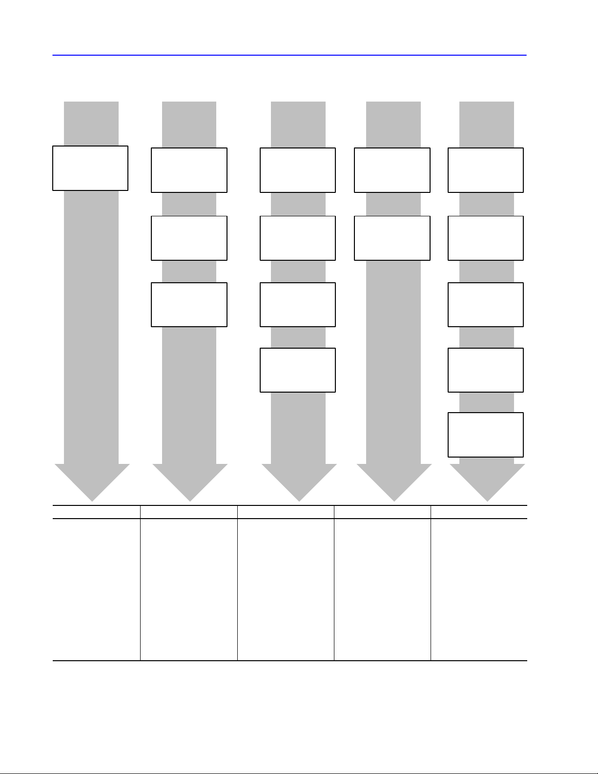
What This Manual Contains
➊Network
Basics
Chapter 1,
Network Layers
➋Protocol
Chapter 2,
Understanding DF1
Protocol
Chapter
3,
Using Halfduplex
Protocol to Send and
Receive Messages
Chapter 4,
Using Fullduplex
Protocol to Send and
Receive Messages
This manual is divided into five units:
➌Message
Packets
Chapter 5,
Datalink Layer
Message Frames
Chapter 6,
Application Layer
Message Packets
Chapter 7,
Communication
Commands
Chapter 8,
Message Packet
Status Codes (STS,
EXT STS)
➍Module
Diagnostics
Chapter 9,
Diagnostic Counters
Chapter 10,
Diagnostic Status
Information
➎Reference
Chapter 1
1,
Data Encoding
Chapter 12,
Uploading and
Downloading
Chapter 13,
PLC Addressing
Chapter 14,
Line Monitor
Examples
➊ ➋ ➌ ➍ ➎
gain an understanding of
the network
•
understand what DF1
protocol is
understand the dif
•
between halfduplex and
fullduplex protocols
ference
•properly configure the
datalink layer of your
software driver
understand each part of a
•
message packet
•
learn message packet
formats for all commands
•asynchronous link status
codes that may be sent in
the STS fields of your
message packet
•diagnostic counters
contained in each interface
module
information returned from
•
each interface when your
computer sends a
diagnostic status command
Chapter 15,
ASCII Codes
•
data encoding and
conversion information
upload and download
•
procedures for the PLC2,
PLC3 and PLC5
processors
information on addressing
•
PLC2, PLC3, PLC5, and
PLC5/250 processors
line monitor examples that
•
show actual commands
being sent and provide an
explanation of each
example
•hex and binary values for
ASCII characters
17706.5.16 October
, 1996
Page 14

About This Manual P–3
Terms and Abbreviations
Term Definition
local node The node sending the command
node The point at which devices, such as programmable controllers,
interface to the network. Each device on a network must have a
unique node address.
In some AllenBradley documentation, you may find the term station
used in place of the term node.
physical link Cable and associated hardware, such as transmitter and receiver
circuits.
PLC controller An AllenBradley programmable controller. See programmable
controller.
protocol Set of programming rules for interpreting the signals transmitted over
the physical link by nodes.
programmable
controller
remote node The node sending the reply to the local node
Abbreviation Definition
ACK acknowledgement. In communication, ACK is a control code sent by
DH+ Data Highway Plus. AllenBradley proprietary network protocol.
NAK negative acknowledgement.
a solidstate control system that has a userprogrammable memory
for storage of instructions to implement specific functions such as I/O
control, logic, timing, counting, report generation, communication,
arithmetic, and data file manipulation. A controller consists of central
processor, input/output interface, and memory. A controller is
designed as an industrial control system.
the receiving node to indicate that the data has been received
without error and the next part of the transmission may be sent.
Related Publications
Publication Name Publication Number
DH/DH+/DH II/DH485 Cable Installation Manual 17706.2.2
DH Overview Product Data 17702.39
DH+ Overview Product Data 17852.6
SCADA System Selection Guide AG2.1
SCADA System Application Guide AG6.5.8
17706.5.16 October
, 1996
Page 15

About This ManualP–4
Related Products
Catalog Number Product Related Documentation
1747KE DH485/RS232 Interface Module 17472.3.7, product data
1770KF2 DH or DH+ Asynchronous (RS232 or RS422A) Interface
1770KF3 DH485 Asynchronous (RS232) Interface Module 17706.5.18, user manual
1771KA2 DH PLC2 Family Communication Adapter Module 17715.2, switch settings
1771KG PLC2 Family RS232 Interface Module 17712.32, product data
1771KGM SCADA Communication Master Module for PLC2 Family 17712.85, product data
1771KE,KF DH RS232 Interface Module 17716.5.16, user manual
1775KA DH PLC3 Communication Adapter Module 17756.5.1, user manual
1775S5,SR5 PLC3 I/O Scanner Module 17756.5.5, user manual
1784KR DH485 Personal Computer Interface Module 17842.23, installation data
1784KT DH+ PC Interface Module 17842.31, installation data
1784KT2/B DH+ PS/2 Interface Module 17842.21, installation data
1784KT2/C 17846.5.16, user manual
1784KTX DH+ PC Interface Module 17846.5.22, user manual
1784KTXD DH+ PC Interface Module
1784PCMK DH+/DH485 PCMCIA communication interface 17846.5.19, user manual
1785KA DH/DH+ Communication Interface Module 17852.6, product data
1785KA3 DH+ PLC2 Family Communication Adapter Module 17852.6, product data
1785KA5 DH+/DH485 Communication Interface Module 17856.5.5, user manual
1785KE DH+ RS232 Interface Module 17856.5.2, user manual
5130RM1,RM2 PLC5/250 Resource Manager Module 50006.2.1, design manual
9351AIX,
DKTS, HPUS,
OSF, VS,
WES, WKTS
9355WABC
Allen-Bradley offers a wide range of interfaces for the DH, DH+,
and DH485 networks, including:
Module
INTERCHANGEt Software
RSLINXt C SDK Software
17476.12, user manual
17706.5.13, user manual
17706.5.13RN1 release notes
17706.5.18RN1, release notes
17706.5.18RN2, release notes
17716.5.1, user manual
17716.5.8, user manual
17716.5.8DU1, document update
17716.5.39, user manual
17716.5.16DU1, document update
17842.23RN1, release notes
17856.5.1, user manual
17856.5.3, user manual
17856.5.3DU1, document update
50006.2.10, installation manual
50006.4.21, reference manual
9398WABCTD11.21.95, data sheet
17706.5.16 October
, 1996
Page 16

About This Manual P–5
Conventions Used in This Manual
"
Communication, diagnostic, and driver software
DH 6001-NET Network Communications Software (Series 6001)
provides a DH driver for many DEC
information, refer to the DH/DH+/DH II
computers. For more
Network Communication
Software Overview (publication 6006-2.3).
We use these conventions in this manual:
This convention: Is used to:
"
call attention to helpful information
refer you to other AllenBradley documents that
might be useful
17706.5.16 October
, 1996
Page 17

Network Basics
Network Layers Chapter 1
Page 18
Chapter 1
Network Layers
Your network is made up of several layers, including:
Nodes send data through the layers.
Application layer serves as the window through which applications access
communication services, including file transfers, virtual terminal functions, and email.
Presentation
Session
applications.
Transport layer performs segmentation and reassembly of messages.
Provides recovery from transmission errors.
Network
Datalink layer runs protocol to guard against errors, detects errors, and corrects
errors. Packages data and puts it onto the physical cable. Manages the flow of the
data bit stream into and out of each network node.
layer manages data formats for the applications.
layer establishes and terminates network communications between
layer establishes connections for communication between network nodes.
Physical layer transmits bits between communication devices.
In this chapter, we discuss the physical, data-link, and application
layers. (We refer to the data-link and application layers as the
software layers.) This chapter contains these sections:
Section Page
Physical Layer 1-2
Software Layers 1-7
Message Packet Structure
1-9
Publication
17706.5.16 - October 1996
Page 19
1–2 Network Layers
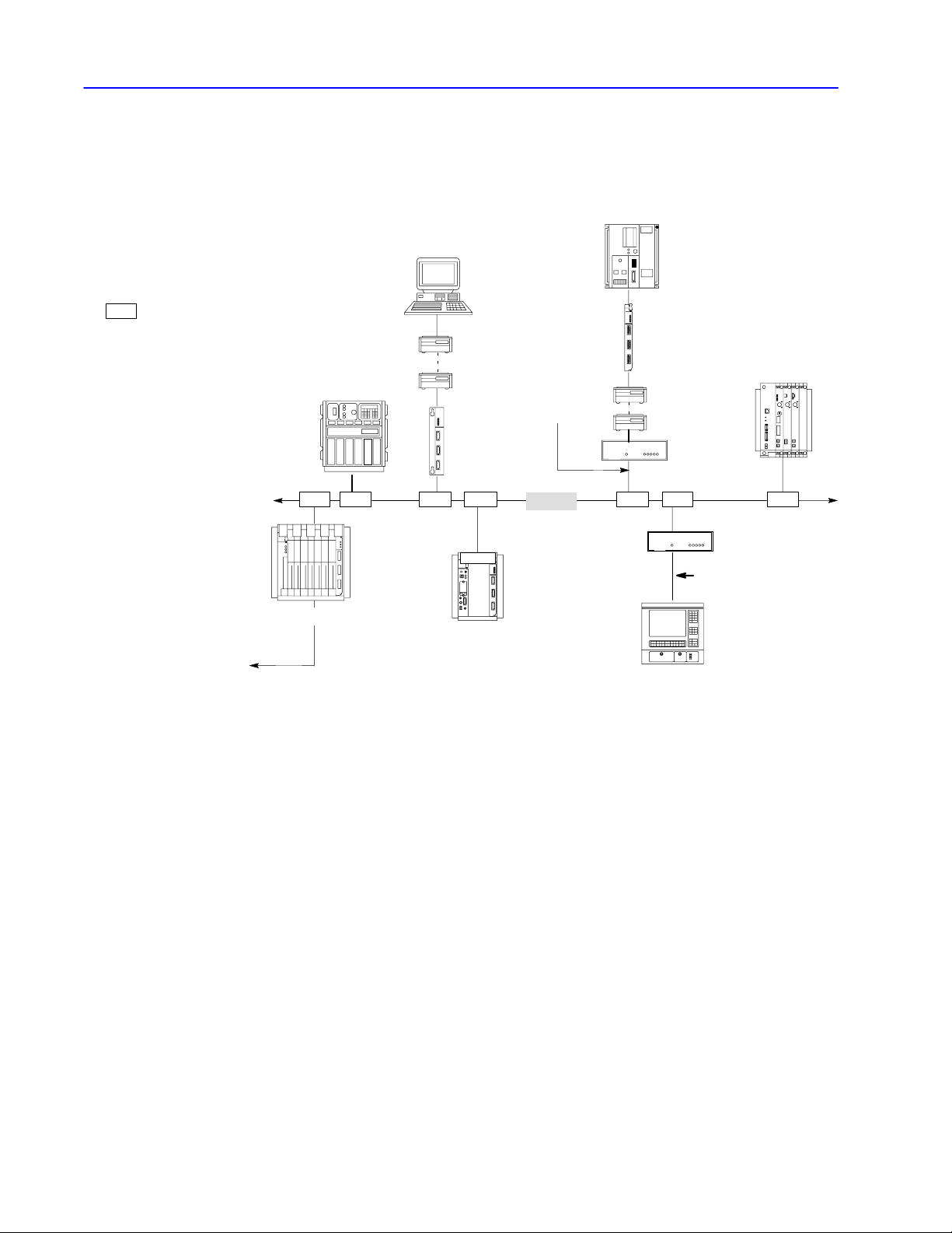
Physical Layer
DF1 link
RS232 Network Interface
network link
DH/DH+/DH485 link
nodes
IBMPC XT, AT or
compatible computer
ControlNet
link
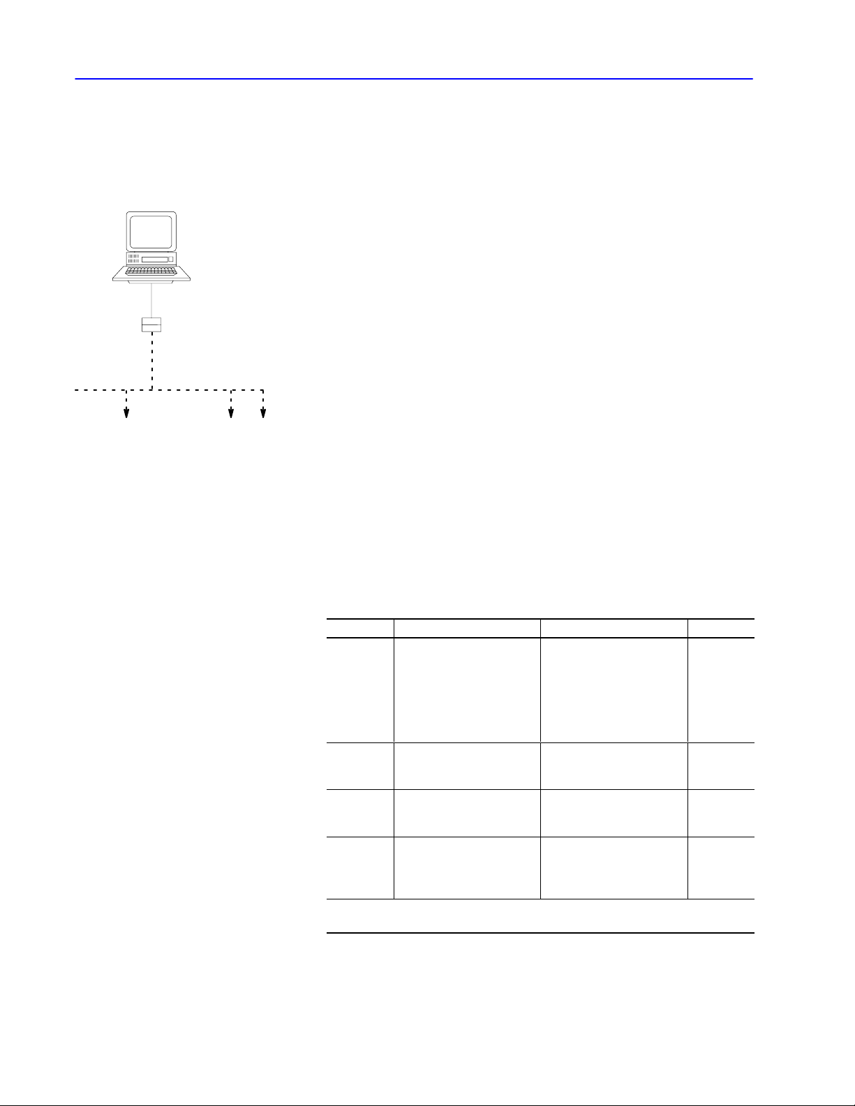
The physical layer is a set of cables and interface modules that
provides a channel for communication between the nodes. A node is
a connection point onto a network, typically containing a unique
address.
When you connect a computer serially to your DH, DH+, DH-485,
or ControlNet link, the interface module acts as an interface between
the:
• DF1 link (RS-232 or RS-422-A)
• network link (DH, DH+, DH485, ControlNet link)
DF1 Link
A DF1 link provides:
• master-slave communication through a half-duplex protocol
• peer-to-peer communication through a full-duplex protocol
This manual provides information necessary to write your own
driver for an intelligent device on a DF1 link. See “Software
Layers,” on page 1–7, for the layers your software driver must
implement so that your intelligent device can talk to other DH,
DH+, DH485, or ControlNet nodes.
Network Link
These network links are available for peer-to-peer communication:
This link Connects And allows See page
•PLC2, PLC3
processors
•color graphic systems
DH
DH+
DH485
ControlNet
➀
Using
up to 255 nodes.
•personal computers
•host computers
•programmable
RS232/RS422 devices
•same devices as DH
•PLC5 processors
•SLC 5/04 processor
•SLC 500 processors
•color graphic systems
•personal computers
•PLC5 processors
•I/O devices
•personal computers
•operator interface devices
bridges (e.g., 1785KA modules), you can extend the length of your DH network to contain
up to 64 nodes
up to 64 nodes 1-5
up to 32 nodes 1-6
up to 99 nodes --------
➀
1-3
Publication
17706.5.16 - October 1996
Page 20

1–3Network Layers
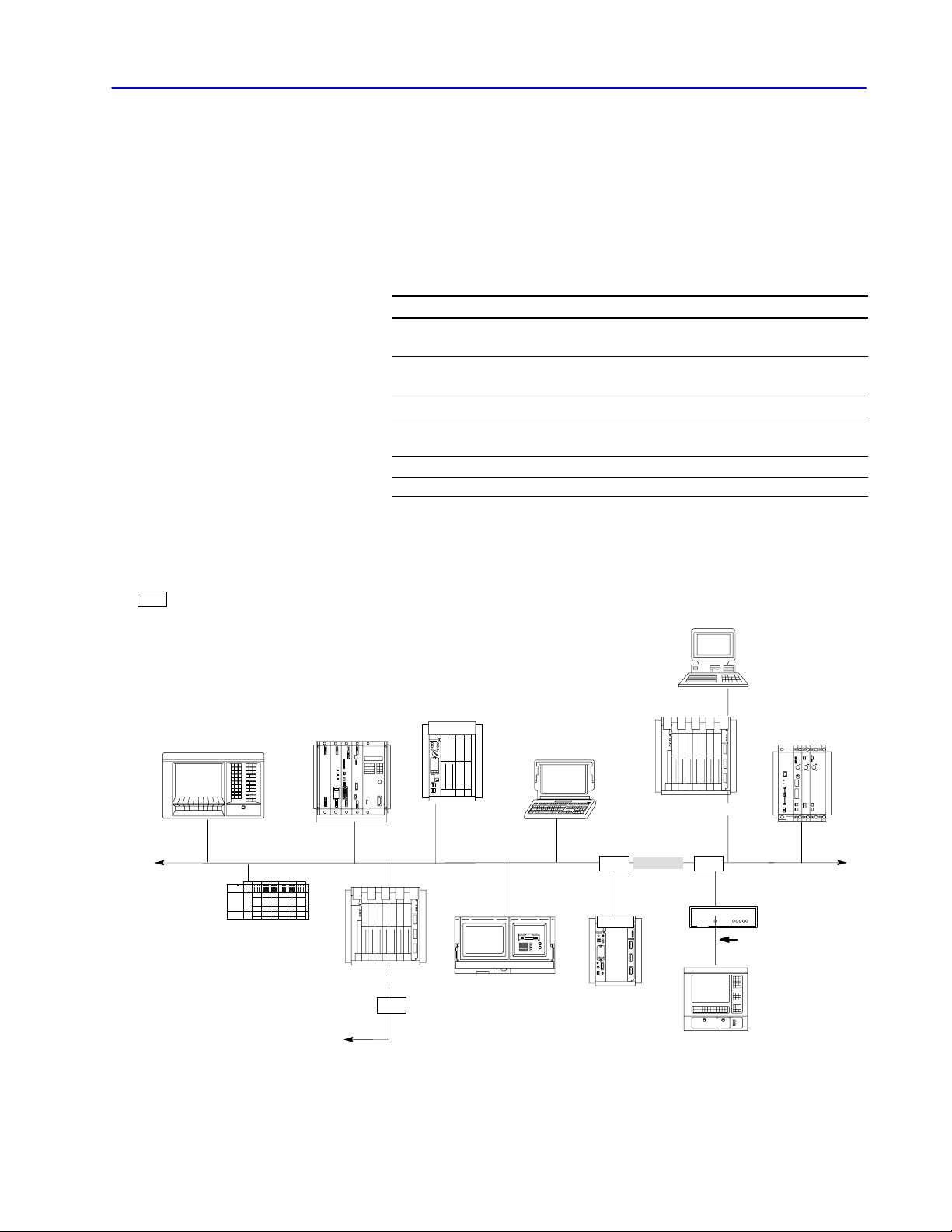
DH Link
A DH link is a local area network (LAN) designed for factory-floor
applications. This link accepts 64 devices and can transmit 57.6 K
bits of data per second.
A DH link consists of a trunk cable up to 10,000 feet (3,048 meters)
long and drop cables as long as 100 feet (30.48 meters) each.
Each node is at the end of a drop cable and connects to the DH link
through a station connector (cat. no. 1770-SC). This is the only
configuration tested and supported by Allen-Bradley.
This processor Connects to a DH link through the
PLC2 family
PLC3
PLC5/250
PLC5, SLC 5/04
➀
Although a PLC5 processor does not directly connect to a DH link, it can communicate with
devices on a DH link via the 1785KA module.
DH PLC2 family communication adapter module
(cat. nos. 1771KA2, KG)
DH PLC3 family communication adapter module
(cat. nos. 1775KA,S5, SR5)
Resource manager module
(cat. nos. 5130KA, RM1,RM2)
DH+/DH communication module
➀
(cat. no. 1785KA)
A DH link implements peer-to-peer communication through a
scheme called the floating master. With this arrangement, each
node has equal access to become the master. The nodes bid for
temporary mastership based on their need to send information.
Publication
17706.5.16 - October 1996
Page 21
1–4 Network Layers
Unlike a master/slave relationship, a floating master relationship
does not require the current master to poll each node to grant
permission to transmit. Therefore, it provides a more efficient
network because there is less overhead—i.e., time—per transaction.
SC
= station connector; 1770SC
PLC3 processor
cat. nos. 1775KA or S5
DH+ link
1785KA
personal computer
modem
modem
DH interface module
cat. nos. 1771KE, KF
SC SC SC SC SC SCSC
PLC2 family processor
cat. no. 1771KA2
RS232C link
(50 cableft. max.)
DH link
PLC2/30 processor
1771KG
PLC5/250 processor
5130RM1
modem
modem
1770KF2
1770KF2
RS232C link
(50 cableft. max.)
T60 industrial workstation running
iew software
ControlV
Publication
17706.5.16 - October 1996
Page 22
1–5Network Layers
DH+ Link
A DH+ link is similar to a DH link, but is optimally used for smaller
networks consisting of limited nodes (about 15 maximum). A DH+
link accepts 64 devices and can transmit data at 57.6, 115.2, or
230.4K bits. (PLC-5/250, SLC, and PLC processors support 57.6
and 115.2K bits; SLC 5/04 processors support 230.4K bits; PLC-5
processors are expected to support 230.4K bits early in 1997.)
This processor Connects to a DH+ link
PLC2
PLC3
through the PLC2 Family Interface module
(cat. no. 1785KA3)
through the I/O Scanner Communication Adapter module
(cat. nos. 1775S5,SR5)
PLC5 directly
PLC5/250
SLC 5/04
➀
➀
You
can configure the data rate for SLC 5/04 processors.
through the Resource Manager module
(cat. nos. 5130KA, RM1, RM2)
directly
A DH+ link implements peer-to-peer communication with a
token-passing scheme to rotate link mastership among the nodes
connected to that link.
SC
= station connector; 1770SC
T71 with 1784KTx
SLC 5/04 processor
PLC3 processor
cat. no. 1775S5
DH link
1785KA
SC
PLC5 processor
T53 programming
terminal with 1784KT
installed
notebook computer
with 1784PCMK
PLC2 processor
cat. no. 1785KA3
(or any other PLC2
processor)
DH+ link
personal computer
1785KE
SCSC
RS232C link
(50 cableft. max.)
PLC5/250 processor
cat. no. 5130RM1
1770KF2
T60 industrial
workstation with
ControlV
iew software
Publication
17706.5.16 - October 1996
Page 23
1–6 Network Layers
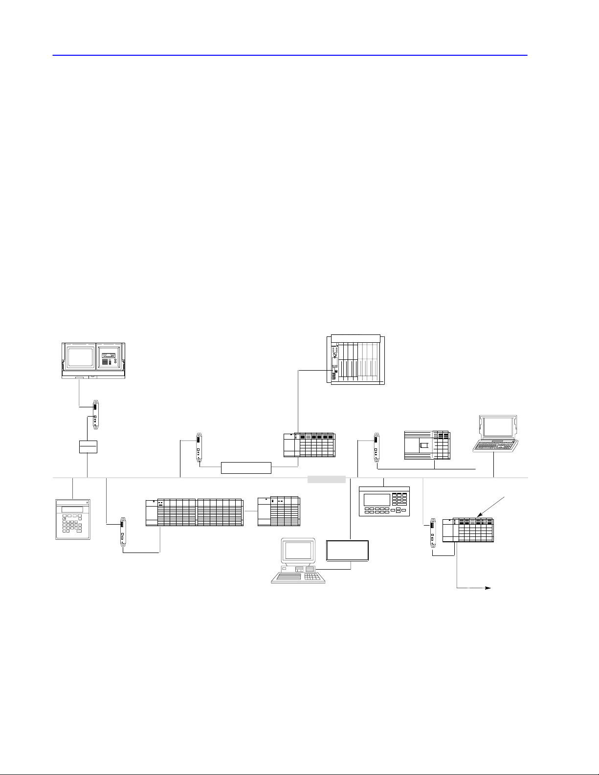
DH485 Link
A DH485 link is a low cost, peer-to-peer programming and
data-acquisition link for a variety of Allen-Bradley products.
DH485 topology is similar to DH and DH+ topology. You can
connect as many as 32 nodes to a DH485 link.
The DH485 link is based on the Electrical Industries Association
(EIA) Standard RS-485 Electrical Signalling Specification.
A variety of Allen-Bradley products (including SLC 500 controllers,
1784-KTX, 1747-KE, 1770-KF3, and operator interface devices) act
as token-passing masters on the DH485 link. This link also supports
a respond-only mode for low-level devices on the link, such as
Allen-Bradley bar code decoders.
A DH485 link implements peer-to-peer communication with a
token-passing scheme to rotate link mastership among the nodes
connected to that link.
T53 programming terminal with a
1784KTX card installed and running
6200 series software
1747AIC
RS232/RS485
converter
DTAM Plus
operator
interface
1747AIC
1747AIC
SLC 5/01 processor
in 17slot modular system
1747PIC
channel 1
À
PLC5 processor
DH+ link
SLC 5/04
processor
channel 0
DH485 link
1770KF3
1747AIC
PanelV
iew 550
operator terminal
SLC 500
fixed 30I/O
controller with
expansion chassis
1747AIC
remote I/O link
notebook compute
with 1784PCMK
1747SN
SLC 5/03
processor
to remote
I/O chassis
Publication
17706.5.16 - October 1996
À
T
o connect an SLC 5/04 to a 1747PIC,
use a 9pin (male) to 25pin (female) adapter.
Page 24

1–7Network Layers
Software Layers
Your DF1 links and network links (DH, DH+, and DH485) each use
two layers of software to enable communication:
• the data-link layer
• the application layer
This figure shows how these layers fit together.
computer
application
common
application
routines
RS232
data link
layer
DH/DH+/DH485
RS232 interface modules
RS232 DH/DH+
link layer
(DF1)
link layer
(network)
DH485
PLC processor
application
common
application
routines
DH/DH+
/DH485 data
link layer
Datalink Layer
This layer controls the flow of communication over the physical link
and:
• determines the encoding of data on the physical medium
• controls who transmits data and who listens using an
arbitration protocol
• conveys data packets intact from the source node to the
destination node over the physical link
"
If your link is Then
you do not need to program this layer.
a DH, DH+ or DH485 link
a DF1 link between AllenBradley
interface modules
a DF1 link between an AllenBradley
interface module and a computer
Your application programs on the network
are not involved with internode protocol,
handshaking, or control of the link.
the interface modules automatically take
care of this layer. Your application
program does not have to be involved with
handshaking control.
you must program this layer at your
computer.
Programming the data-link layer
You can program the data link layer using DF1 protocol.
For more information, see Chapter 3, “Using Half-duplex Protocol to
Send and Receive Messages,” or Chapter 4, “Using Full-duplex
Protocol to Send and Receive Messages.”
Publication
17706.5.16 - October 1996
Page 25
1–8 Network Layers
Application Layer
This layer controls and executes the actual commands specified in
the communication between nodes. This layer is the same for both
DF1 and network links. The application layer:
• interfaces to user processes and databases
• interprets commands
• formats user data into packets
The application layer depends upon the type of node the application
is running on since it must interface to the user process and interpret
the user database.
"
Processes in the application layer
The application layer is typically organized into two types of
processes:
• senders — A sender, after receiving a signal from the user
process, sends a message and awaits a reply. It then sends the
results to the user process.
• responders — A responder waits for an incoming message from
the link. When the responder receives a message, it performs the
indicated operation on the user data base and returns a reply
message to the sender.
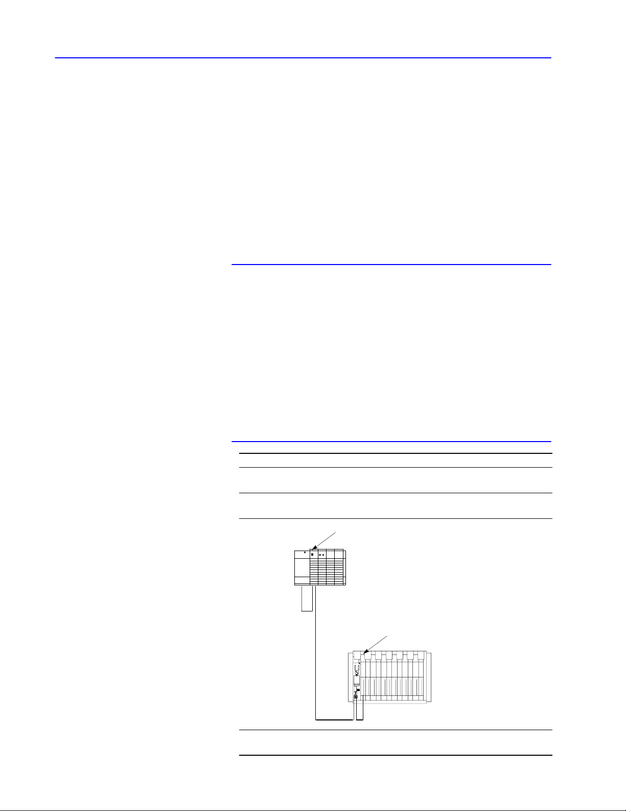
If your physical link is Then
a network link
a DF1 link between AllenBradley interface
modules
1747KE
SLC 5/02
processor
the communication modules automatically
take care of this layer.
the interface modules automatically take
care of this layer. (See figure below.)
Publication
17706.5.16 - October 1996
DH485 link
RS232
DF1 fullduplex
a DF1 link between an AllenBradley
interface module and a computer
1785KE
PLC5/15
processor
DH+ link
you will need to program this layer at your
computer.
Page 26

1–9Network Layers
Message Packet Structure
"
Messages
See Chapter 7, “Communication Commands,” for:
• a description of the command messages for each type of
PLC processor
• information on how to program the application layer fields of a
message packet for an asynchronous link
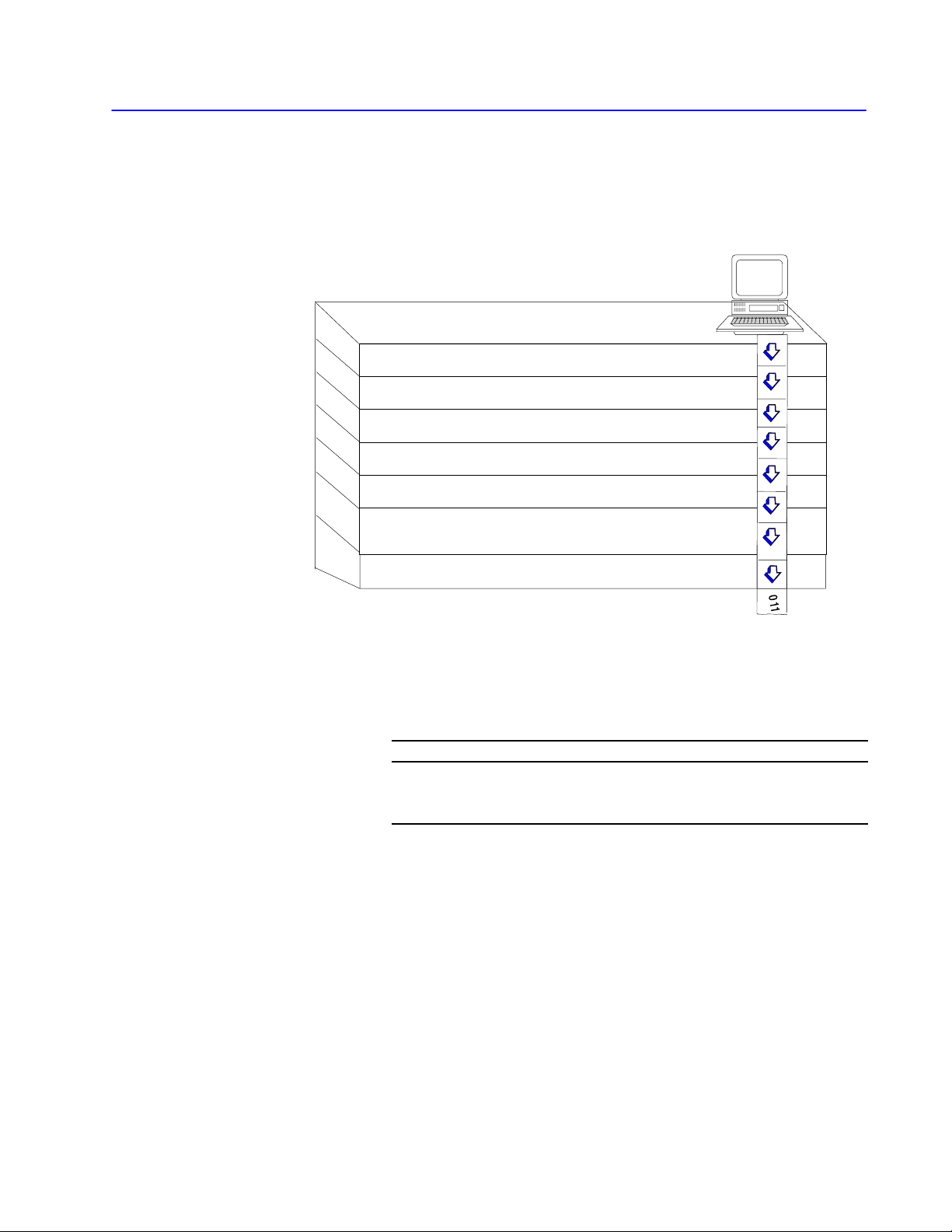
All messages on a network have the same fundamental structure,
regardless of their function or destination. If you could freeze a
message packet while it is in transmission, you would see:
Bytes Contents
Information used by the application and datalink layers of your software to
get the message to its destination:
protocol
data
•If a transaction originates from a PLC processor, the interface module
automatically fills the protocol bytes.
•If the transaction originates from a computer, your computer software
must supply the necessary protocol.
Information supplied by application program at the source and delivered to
the application program at the destination.
The following sections describe bytes that you define using the
application-layer protocol bytes in your message packet.
For a detailed description of how to use these bytes for each type of
command, see Chapter 7, “Communication Commands.”
To define this See this page
command and reply message 1-9
message priority 1-10
delivery order of commands 1-10
types of commands 1-11
error codes
1-11
Command and Reply Message
A network transaction consists of a command and a reply.
The two parts provide extra data integrity by making sure that a
required action always returns a reply with some sort of status, either
zero status for a good reply, or non-zero status as an error code.
The application-layer protocol distinguishes a command from a
reply. The data area of a command and its corresponding reply
depend on the type of command.
Publication
17706.5.16 - October 1996
Page 27

1–10 Network Layers
Message Priority
You specify the priority level for each DH command in the message
command code. The node that receives a command message must
establish the same priority level for its corresponding reply message:
This link Classifies a message as
high priority or normal priority
Priority levels of messages determine the order in which nodes transmit
DH
DH+ normal priority
DH485 normal priority
Important: Nodes with high priority messages are given priority
messages on a DH link. In the polling process, nodes with high priority
messages will always be given priority over nodes with normal priority
messages.
over nodes with normal priority messages throughout
the command/reply message cycle. For this reason, a
command should be given a high priority designation
only when special handling of specific data is required.
Using an excessive number of high-priority commands
defeats the purpose of this feature and could delay or
inhibit the transmission of normal priority messages.
Delivery Order of Commands
The sending node, the network, and the receiving node execute
commands based on network conditions, including—but not limited
to:
• nodes buffering commands
• retries due to noise on the network
• priority levels
If your application requires that commands be delivered in a specific
order, your logic must control the initiation of one command at a
time on the network and verify delivery before initiating additional
commands. This verification is completed by:
• a done bit or an error bit in a PLC processor
• a reply message in a computer
A done bit or a successful reply causes the next command to be
initiated. If an error bit or a reply with non-zero status is returned,
you must decide the appropriate action based on your application.
Important: If any node on the network initiates multiple commands
(for example, the sending node sets multiple bits at any
one time), the order in which these commands get
executed at the receiving node cannot
be guaranteed.
Publication
17706.5.16 - October 1996
Page 28

1–11Network Layers
Types of Commands
From your computer on a DF1 link to a node on a DH, DH+ or
DH485 link, you can send four types of commands:
• read
• write
• diagnostic
• upload/download
For additional information on the commands you can send,
see Chapter 7, “Communication Commands.”
Error Codes
When your computer sends a command on the asynchronous link, a
status code is returned in the reply message. This code tells you the
status of the command sent from your computer. You must program
your computer to interpret this code. For more information on codes
and their meanings, see Chapter 8, “Message Packet Status Codes.”
Error codes can be generated at two places:
• the sending node
• the receiving node
For codes that are returned from the sending node:
From this node Error codes are generated when
•an application program used the wrong message format or issued
sending node
receiving node
illegal commands.
•the sending node cannot complete a transaction due to network
problems.
an application problem exists at the receiving node. Typically, these
involve:
•the PLC processor being off line (in Program mode, for example)
or
•the command trying to access a memory area is blocked by the
interface module or user application program (i.e., the data table
location does not exist or is restricted).
Publication
17706.5.16 - October 1996
Page 29

Protocol
Understanding DF1 Protocol Chapter 2
Using Halfduplex Protocols to Send and Receive
Messages Chapter 3
Using Fullduplex Protocols to Send and Receive
Messages Chapter 4
Page 30

Chapter 2
Understanding DF1 Protocol
If you are connecting an interface module to a computer, you must
program the computer to understand and issue the proper protocol
character sequences. This chapter describes the DF1 protocol you
can use with your DF1-link driver for:
• peer-to-peer (two-way simultaneous) communication
• master-slave (two-way alternate) communication
This chapter includes these sections:
Section Page
DF1 Protocol 2-2
Character Transmission 2-5
Transmission Symbols
Important: The 1784-KT and 1784-KT2 cards connect directly to
DH+; the 1784-KR card connects directly to DH-485.
As a result, an asynchronous RS-232 interface is not
used and the information in this chapter does not apply
to software written for these cards, which use the
Standard Driver software.
2-6
Publication
17706.5.16 - October 1996
Page 31

2–2 Understanding DF1 Protocol
DF1 Protocol
A link protocol is a set of programming rules for interpreting the
signals transmitted over a physical link. A protocol, such as DF1:
• carries a message, error free, from one end of the link to the other
It has no concern for the content of the message, the function of
the message, or the ultimate purpose of the message.
For example, with full-duplex DF1 protocol, it accomplishes this
by attaching a check character (BCC) or check characters (CRC)
to the end of each command and reply. The device receiving the
command or reply then verifies the BCC or CRC and returns an
ACK—if the BCC or CRC is acceptable—or an NAK—if the
BCC or CRC does not check.
• indicates failure with an error code
Internally, the link protocol must delimit messages, detect and
signal errors, retry after errors, and control message flow.
DF1 protocol is an Allen-Bradley data-link layer protocol that
combines features of subcategories D1 (data transparency) and F1
(two-way simultaneous transmission with embedded responses) of
ANSI x3.28 specification. There are two categories of DF1
protocol:
• half-duplex protocol (master-slave communication)
• full-duplex protocol (peer-to-peer communication)
Halfduplex Protocol
Half-duplex protocol is a multidrop protocol for one master and one
or more slaves. With half-duplex protocol, you can have 2 to 255
nodes simultaneously connected on a single link; this link operates
with all nodes interfaced through half-duplex modems. (For a list of
devices that can be used as masters and slaves, see page 3–2. For
more on half-duplex protocol, refer to Chapter 3, “Using Half-duplex
Protocol to Send and Receive Messages.”)
To implement half-duplex protocol, use the following
communication characteristics:
• 8 bits per character
• no parity
• 1 stop bit
Publication
17706.5.16 - October 1996
Page 32

2–3Understanding DF1 Protocol
"
Using half-duplex protocol
When you use half-duplex protocol, the intended environment is a
multidrop link with all nodes interfaced through half-duplex
modems. Unless there is only one slave directly connected to a
master, you must use a modem. Your modems must support these
signals:
• request-to-send (RTS)
• clear-to-send (CTS)
• data-carrier-detect (DCD)
• data-set-ready (DSR)
• data-terminal-ready (DTR)
If your modem does not support the DCD and DSR signals, you
must jumper DCD and DSR to DTR.
You designate one node as master to control which node has access
to the link. All other nodes are slaves, and must wait for permission
from the master before transmitting. Each slave node has a unique
node number between 0 and 254 (decimal).
"
The master can send and receive messages to and from each node on
the multidrop link and to and from every node on network links
connected to the multidrop link.
If the master is programmed to relay messages, then nodes on the
multidrop link can engage in virtual slave-to-slave communication.
This communication is transparent to the application.
Multiple masters are not allowed, except when one acts as a
backup to the other and does not communicate unless the primary is
shut down.
Slave-to-slave communication
In slave-to-slave communication, the master looks at the packet
received from the slave. If the packet is not for the master,
the master reassembles the packet as a master packet and sends the
packet to slave devices.
Publication
17706.5.16 - October 1996
Page 33

2–4 Understanding DF1 Protocol
Fullduplex Protocol
Use full-duplex protocol:
• over a point-to-point link that allows two-way simultaneous
transmission
• over a multidrop link where interface modules are able to
arbitrate transmission on the link
• for high performance applications where it is necessary to get the
highest possible throughput from the available medium
If you connect an interface module to another Allen-Bradley
communication interface module, the modules automatically handle
the link arbitration. (For a list of modules that automatically handle
link arbitration, refer to page 4–1.)
"
Full-duplex dial-up modems
Full-duplex dial-up modems can be used as long as a carrier is
detected before the carrier timeout (about 10 seconds). If a carrier is
not sensed before the timeout, the module drops DTR to trigger the
modem to hang up the phone. A carrier must be sensed at least
every 10 seconds to maintain the connection.
Publication
17706.5.16 - October 1996
Page 34

2–5Understanding DF1 Protocol
Character Transmission
Allen-Bradley interface modules send data serially over the
RS-232-C/RS-422-A interface, one 10-bit byte—11-bit byte with
parity—at a time. The transmission format conforms to ANSI
X3.16, CCITT V.4, and ISO 1177 standards, with the exception that
the parity bit is retained while the data length is extended to eight
bits. Make sure that your computer conforms to this mode of
transmission. The transmission format is:
No Parity
start bit
data bit 0
data bit 1
data bit 2
data bit 3
data bit 4
data bit 5
data bit 6
data bit 7
one stop bit
With Parity
start bit
data bit 0
data bit 1
data bit 2
data bit 3
data bit 4
data bit 5
data bit 6
data bit 7
even parity bit
one stop bit
For all DH, DH+, and DH485 interface modules, you must comply
with this transmission format. For communication rates and parity
settings, refer to your module’s user manual.
Publication
17706.5.16 - October 1996
Page 35

2–6 Understanding DF1 Protocol
Transmission Symbols
Both half-duplex and full-duplex protocols are character-oriented.
They use the ASCII control characters in the tables below, extended
to eight bits by adding a zero for bit 7:
Table 2.A
Halfduplex Protocol
Abbreviation
STX 02 0000 0010
SOH 01 0000 0001
ETX 03 0000 0011
EOT 04 0000 0100
ENQ 05 0000 0101
ACK 06 0000 0110
DLE 10 0001 0000
NAK 0F 0000 1111
Table 2.B
Fullduplex Protocol
Abbreviation
STX 02 0000 0010
ETX 03 0000 0011
ENQ 05 0000 0101
ACK 06 0000 0110
DLE 10 0001 0000
NAK 0F 0000 1111
Hexadecimal Value Binary Value
Hexadecimal Value Binary Value
(For the standard definition of these characters, refer to the ANSI
X3.4, CCITT V.3, and ISO 646 standards.)
A symbol is a sequence of one or more bytes having a specific
meaning to the link protocol. The component characters of a
symbol must be sent one after another with no other characters
between them. DF1 protocol combines the characters listed in the
tables above into control and data symbols:
• Control symbols are fixed symbols required by the DF1 protocol
to read a particular message
• Data symbols are variable symbols which contain the application
data for a particular message
Publication
17706.5.16 - October 1996
Page 36

Table 2.C
Halfduplex Transmission Symbols
2–7Understanding DF1 Protocol
Symbol
Type Meaning
DLE SOH control symbol
DLE STX control symbol
DLE ETX
BCC/CRC
control symbol Sender symbol that terminates a message.
DLE ACK control symbol
DLE NAK control symbol
DLE ENQ control symbol
DLE EOT
BCC
control symbol
STN data symbol
APP DATA data symbol
DLE DLE data symbol
Sender symbol that indicates the start of a master
message.
Sender symbol that separates the multidrop
header from the data.
Response symbol which signals that a message
has been successfully received.
Global link reset command only issued by the
master. Causes the slaves to cancel all messages
that are ready to transmit to the master. Typically,
the slave returns the message and an error code to
the originator.
Sender symbol, issued only by the master, that
starts a poll command.
Response symbol used by slaves as a response to
a poll when they have no messages to send.
Station number of the slave node on your
halfduplex link.
Single characters having values 000F and 11FF.
Includes data from application layer including user
programs and common application routines. A data
is sent as 10 10 (DLE DLE).
10
16
Represents the data value or STN value
of 10
. See APP DATA.
16
Publication
17706.5.16 - October 1996
Page 37

2–8 Understanding DF1 Protocol
Table 2.D
Fullduplex Transmission Symbols
Symbol
DLE STX control symbol
DLE ETX
BCC/CRC
DLE ACK control symbol
DLE NAK control symbol
DLE ENQ control symbol
Type Meaning
Sender symbol that indicates the start of a message
frame.
control symbol Sender symbol that terminates a message frame.
Response symbol which signals that a message
frame has been successfully received.
Response symbol which signals that a message
frame was not received successfully.
Sender symbol that requests retransmission of a
response symbol from the receiver.
Single character data values between 000F and
APP DATA data symbol
11FF. Includes data from application layer including
user programs and common application routines.
A data 10
is sent as 10 10 (DLE DLE).
16
DLE DLE data symbol Represents the data value of 1016.
Publication
17706.5.16 - October 1996
Page 38

Chapter 3
Using Halfduplex Protocols to
Send and Receive Messages
In half-duplex protocol, devices share the same data circuits,
therefore only one device can “talk” at a time. Half-duplex protocol
can be likened to a one-lane bridge: each car must wait its turn to
cross the bridge. (To compare half-duplex to full-duplex protocol,
refer to Chapter 4, “Using Full-duplex Protocols to Send and
Receive Messages.”)
Read this chapter to help learn how to use half-duplex protocol to
send and receive messages. It contains these sections:
Section Page
Halfduplex Protocol Message Transmission 3-2
Transmitter and Receiver Message Transfer 3-3
Halfduplex Protocol Environment 3-3
Message Characteristics 3-7
Master Polling Responsibilities 3-7
Slave Transceiver Actions 3-9
Halfduplex Protocol Diagrams
3-11
Publication
17706.5.16 - October 1996
Page 39

3–2 Using Half-duplex Protocols to Send and Receive Messages
Halfduplex Protocol Message
Transmission
Half-duplex protocol:
• is a multidrop protocol for one master and one or more slaves
• provides a lower data throughput than full-duplex
• allows communication with each node on the multidrop link
• allows communication with nodes on links connected to the
multidrop link
If the master is programmed to relay messages, then nodes on the
multidrop can engage in virtual slave-to-slave transfers. Half-duplex
protocol operates on a multidrop link with all nodes interfaced
through half-duplex modems. There may be from 2 to 255 nodes
simultaneously connected to a single link.
In half-duplex mode, one node is designated as master and it
controls which node has access to the link. All other nodes are
called slaves and must wait for permission from the master before
transmitting. Allen-Bradley devices with master and slave
capabilities include:
Devices with master capability Devices with slave capability
•SLC 5/03 and 5/04 (on channel 0)
•1771KGM DH SCADA Master module •1770KF2, KF3, KFC
•5130RM1, RM2, KA (channel 1) •1775KA (via modem port)
•5130RM2 •1785KE
•a userprogrammed intelligent device •1771KE, KF, KG
•a personal computer running ControlView
software
•PLC5/11 5/20, 5/30, 5/40, 5/60,
PLC5/80 (on channel 0)
•personal computer running
WINtelligentt LINXt software
•personal computer running RSLINXt
À
SLC 5/03 and 5/04 processors (OS302 and OS401, respectively) now support halfduplex DF1
masters.
À
•1747KE
•PLC5/11 5/20, 5/30, 5/40, 5/60,
PLC5/80 (on channel 0)
•SLC 5/03 and 5/04 (on channel 0)
•5130RM1, RM2, KA (channel 1)
•personal computer running
WINtelligentt LINXt software
•personal computer running RSLINXt
Publication
With half-duplex protocol, you can use a:
• two-circuit system – master sends and slaves receive on one
circuit, slaves send and master receives on the other
• one-circuit system – master and slaves send and receive on the
same circuit
17706.5.16 - October 1996
Page 40

3–3Using Half-duplex Protocols to Send and Receive Messages
Transmitter and Receiver Message Transfer
Each node on a multidrop link contains a software routine to transmit
and receive messages. DH and DH+ interface modules already
contain a slave transceiver routine, so they can be configured to
function as slave nodes in half-duplex mode.
Instead of a single routine, you can program separate transmitter and
receiver routines. However, in this chapter, we assume you are using
a single routine. The master and slave transmitter/receivers are
illustrated in the figure below:
source
sink
packet
OK
packet
OK
master transceiver
physical linkto other slaves
packet
OK
source
Halfduplex Protocol
Environment
slave transceiver
packet
OK
sink
(The “source” and “sink” are defined in the next section,
“Half-duplex Protocol Environment.”
To define the environment of the protocol, the transceiver:
• needs to know where to get the message it sends, the message
source. We assume the message source:
– supplies one message at a time upon request from the
transceiver
– requires notification of the success or failure of the transfer
before supplying the next message
• must have a means of disposing of messages it receives, the
message sink
When the transceiver has received a message successfully, it attempts
to give it to the message sink. If the message sink is full,
the transceiver will receive an indication that the sink is full.
Publication
17706.5.16 - October 1996
Page 41

3–4 Using Half-duplex Protocols to Send and Receive Messages
The following program describes the actions of the transceiver in
detail:
TRANSCEIVER
variables
LAST-HEADER = invalid
loop
is defined
LAST
-HEADER is 4 bytes copied out of the last good message
BCC is an 8-bit block check accumulator
reset parity error flag
GET-CODE
if it’
s a DLE SOH then
begin
end
else if it’
begin
end
else if it’
send a success code to the message source and discard the
message
else if it’
while the message source can supply a message
end
GET-CODE
if it’
s a data code and it matches the station number or it
is 255 (the broadcast address) then
begin
BCC = the data code
GET-CODE
if it’
s a DLE STX then
begin
RESPONSE = GETMESSAGE
if RESPONSE is ACK then
begin
if message header is dif
last and sink is not full
begin
save new HEADER
try to send message to sink
end
if this is not a broadcast message
and sink was not full then
begin
turn on R
wait for CTS
send DLE ACK
turn of
end
s a DLE ENQ then
GET
-CODE (the station number)
GET-CHAR (the BCC)
check the station number and the BCC, and if they’re OK then
begin
if there is a message left over from the last time and
the transmit counter is exceeded then
if there is no message then
turn on R
wait for CTS
if there is still no message then send a DLE EOT
else SEND the message
turn of
end
s a DLE ACK then
s a DLE NAK then
begin
get a message from the message source
discard the message
send an error code to the message source
end
end
throw the message away and send an error code to the
message source
try to get one from the message source
TS
f RTS
end
end
ferent from
TS
f RTS
Publication
17706.5.16 - October 1996
Page 42

3–5Using Half-duplex Protocols to Send and Receive Messages
GETMESSAGE
GET-CODE
while it is data code
if it is a control code and it is an ETX then
else end
GET-CODE is defined as
loop
end
is defined as
begin
if buf
fer is not overflowed put data in buf
GET-CODE
end
begin
if parity error flag is set then return a NAK
if BCC is not zero then return a NAK
if message is too small then return a NAK
if message is too large then return a NAK
return an ACK
end
variable
GET-CHAR
if char is not a DLE
begin
add char to BCC
return the char and a data flag
end
else
begin
GET-CHAR
if char is a DLE
begin
add char to BCC
return a DLE and a data flag
end
else if char is an ETX
else return char with a control flag
end
end
begin
GET-CHAR
add char to BCC
return ETX with a control flag
end
fer
GETCHAR is defined as
an implementationdependent function that returns one byte of data
from the link interface hardware
SEND (Message) is defined as
begin
BCC = 0
send DLE STX
for every byte in the message do
begin
subtract the byte from the BCC
send the corresponding data code
end
send DLE ETX BCC
end
Publication
17706.5.16 - October 1996
Page 43

3–6 Using Half-duplex Protocols to Send and Receive Messages
The following flowchart shows the software logic for implementing
half-duplex protocol from the master node’s point of view:
XCVR
Yes
Yes
Does master
have message
to send?
No
Select node
Send poll
Start timeout
Receive
DLE
EOT?
Yes
Node
in active
list?
No
Add node to
active list
No Yes
Receive
message?
No Yes
No
Active
node?
Yes
Message
OK?
Duplicate
message?
No
Send message to
application layer
No
Yes
Send DLE ACK
Get message from
application layer
Send message
Start timeout
Yes
Received
DLE
ACK?
3
timeouts
this
message?
No
No
Yes
3
timeouts
this poll?
Yes
Tell application
layer of failure
Add node to
inactive list
Send DLE ACK
No
Publication
17706.5.16 - October 1996
Page 44

8VLQJ +DOIGXSOH[ 3URWRFROV WR 6HQG DQG 5HFHLYH 0HVVDJHV
ï
0HVVDJH &KDUDFWHULVWLFV
0DVWHU 3ROOLQJ
5HVSRQVLELOLWLHV
,GHDOO\ WKH GDWDOLQN OD\HU SURWRFRO LV QRW FRQFHUQHG ZLWK WKH FRQWHQW
RU IRUP RI WKH PHVVDJHV LW LV WUDQVIHUULQJ +RZHYHU KDOIGXSOH[
SURWRFRO SODFHV WKH IROORZLQJ UHVWULFWLRQV RQ WKH PHVVDJHV WKDW DUH
VXEPLWWHG WR LW IRU WUDQVIHU
0LQLPXP VL]H RI OLQNOD\HU GDWD LV E\WHV
0D[LPXP VL]H RI OLQNOD\HU GDWD GHSHQGV RQ WKH DSSOLFDWLRQOD\HU
FRPPDQG
6RPH SURWRFRO LPSOHPHQWDWLRQV UHTXLUH WKDW WKH ILUVW E\WH RI D
PHVVDJH PDWFK WKH QRGH DGGUHVV WKXV UHFHLYHUV LJQRUH PHVVDJHV
WKDW GR QRW FRQWDLQ WKH FRUUHFW DGGUHVV 7KLV ILOWHULQJ FDQ
RSWLRQDOO\ EH SHUIRUPHG E\ WKH PHVVDJH VLQN
$V SDUW RI WKH GXSOLFDWH PHVVDJH GHWHFWLRQ DOJRULWKP WKH UHFHLYHU
FKHFNV WKH VRXUFH 65& FRPPDQG &0' DQG WUDQVDFWLRQ
716 ILHOGV RI HDFK PHVVDJH 7KHUH PXVW EH D GLIIHUHQFH LQ DW
OHDVW RQH RI WKHVH E\WHV EHWZHHQ D PHVVDJH DQG WKH SUHYLRXV
PHVVDJH 2WKHUZLVH WKH PHVVDJH LV FODVVLILHG DV D UHWUDQVPLVVLRQ
RI WKH SUHYLRXV PHVVDJH )RU PRUH LQIRUPDWLRQ RQ WKHVH ILHOGV
VHH SDJHV 12 7$*12 7$* DQG 12 7$*
7KH PDVWHU SROOLQJ DOJRULWKP YDULHV GHSHQGLQJ RQ WKH H[SHFWHG IORZ
RI WUDIILF WKURXJK WKH V\VWHP $ VLPSOH PDVWHU FRQWLQXRXVO\ SROOV
HDFK VODYH LQ ´URXQGURELQµ IDVKLRQ ,I D PHVVDJH LV UHFHLYHG LW LV
KDQGOHG WKHQ WKH QH[W QRGH LV SROOHG ,Q DGGLWLRQ WR JHQHUDO
UHVSRQVLELOLWLHV PDVWHUV DUH UHVSRQVLEOH IRU
GHWHFWLQJ GXSOLFDWHV
SROOLQJ LQDFWLYH VODYHV
UHOLHYLQJ IXOO VLQNV
XVLQJ VLPSOLILHG QHWZRUN OD\HU
VODYHWRVODYH PHVVDJH UHOD\LQJ
'XSOLFDWH 'HWHFWLRQ
'XSOLFDWH GHWHFWLRQ LQIRUPDWLRQ PXVW EH NHSW IRU HDFK QRGH XQOHVV
WKH PDVWHU SROOV HDFK QRGH UHSHDWHGO\ XQWLO LW LV HPSW\ EHIRUH
SURFHHGLQJ WR WKH QH[W 7KHQ GXSOLFDWH GHWHFWLRQ LQIRUPDWLRQ RQO\
QHHGV WR EH NHSW IRU WKH FXUUHQW QRGH
,QDFWLYH 6ODYH 3ROOLQJ
,I D VODYH IDLOV WR UHVSRQG WR D SROO WKH PDVWHU UHPRYHV WKH VODYH
IURP WKH OLVW RI DFWLYH VODYHV 7R VDYH WLPH WKH PDVWHU SROOV WKH
DFWLYH VODYHV RQ D UHJXODU EDVLV DQG SROOV WKH LQDFWLYH VODYHV
RFFDVLRQDOO\ WR VHH LI WKH\ UHVSRQG :KHQ DQ LQDFWLYH VODYH GRHV QRW
UHVSRQG WR D SROO LW LV SXW EDFN LQWR WKH DFWLYH VODYH OLVW
3XEOLFDWLRQ ï 2FWREHU
Page 45

ï
8VLQJ +DOIGXSOH[ 3URWRFROV WR 6HQG DQG 5HFHLYH 0HVVDJHV
)XOO 6LQNV
:KHQ D QRGH WLPHV RXW WR D PHVVDJH FRPPDQG SROO WKH QRGH WR VHH
LI LW UHVSRQGV ,I LW UHVSRQGV WR WKH SROO ZLWK D '/( (27 EXW
FRQVLVWHQWO\ IDLOV WR $&. D PHVVDJH LWV VLQN LV SUREDEO\ IXOO
<RX PXVW ZDLW IRU WKH EXIIHUV WR FOHDU EHIRUH VHQGLQJ DQRWKHU
PHVVDJH
%XIIHUIXOO FRQGLWLRQ
6RPH GHYLFHV KROG GDWD LQGHILQLWHO\ 7R JHW WKH GDWD DQG UHOLHYH WKH
EXIIHUIXOO FRQGLWLRQ \RX PXVW SROO WKH GHYLFH
:KHQ D QRGH·V PHVVDJH VRXUFH DQG VLQN VKDUH D FRPPRQ PHPRU\
SRRO DQ DEXQGDQFH RI PHVVDJHV LQ WKH PHVVDJH VRXUFH PD\ FDXVH D
PHVVDJH VLQN IXOO LQGLFDWLRQ ,Q WKLV FDVH WKH PDVWHU FDQ SROO WKH
QRGH WR UHFHLYH PHVVDJHV DQG PDNH PHPRU\ DYDLODEOH :DLWLQJ IRU
WKH PHPRU\ WR FOHDU RQ LWV RZQ PD\ QRW ZRUN RQ DOO GHYLFHV WKH RQO\
ZD\ WR IUHH PHPRU\ LV WR KDYH WKH PDVWHU SROO WKH QRGH
6LPSOLILHG 1HWZRUN /D\HU
7R DOORZ SHHUWRSHHU FRPPXQLFDWLRQ RQ WKH PXOWLGURS \RXU PDVWHU
PXVW XVH D VLPSOLILHG QHWZRUN OD\HU 7KLV QHWZRUN OD\HU UHVLGHV MXVW
DERYH WKH GDWDOLQN OD\HU DQG SHUIRUPV URXWLQJ DQG UHOD\LQJ RI
PHVVDJHV )RU PRUH RQ WKH QHWZRUN OD\HUV UHIHU WR &KDSWHU
´1HWZRUN /D\HUVµ
3XEOLFDWLRQ ï 2FWREHU
Page 46

8VLQJ +DOIGXSOH[ 3URWRFROV WR 6HQG DQG 5HFHLYH 0HVVDJHV
ï
6ODYH 7UDQVFHLYHU $FWLRQV
:DLWV IRU PHVVDJH
5HFHLYHV PHVVDJH
6LQFH LQSXW VHQW WR WKH WUDQVFHLYHU FDQ RIWHQ EH DIIHFWHG E\ QRLVH
IURP WKH SK\VLFDO ZRUOG WKH WUDQVFHLYHU PXVW EH FDSDEOH RI
UHVSRQGLQJ WR PDQ\ DGYHUVH VLWXDWLRQV VXFK DV
7KH PHVVDJH VLQN FDQ EH IXOO OHDYLQJ QRZKHUH WR SXW D PHVVDJH
$ PHVVDJH FDQ FRQWDLQ D SDULW\ HUURU
7KH %&&&5& FDQ EH LQYDOLG
7KH '/( 62+ '/( 67; RU '/( (7; %&&&5& PD\ EH
PLVVLQJ
7KH PHVVDJH FDQ EH WRR ORQJ RU WRR VKRUW
$ VSXULRXV FRQWURO RU GDWD V\PERO FDQ RFFXU RXWVLGH D PHVVDJH
$ VSXULRXV FRQWURO V\PERO FDQ RFFXU LQVLGH D PHVVDJH
7KH '/( $&. UHVSRQVH FDQ EH ORVW FDXVLQJ WKH WUDQVPLWWHU WR
VHQG D GXSOLFDWH FRS\ RI D PHVVDJH WKDW KDV DOUHDG\ EHHQ SDVVHG
WR WKH PHVVDJH VLQN
7KH VODYH LV DOZD\V LQ D SDVVLYH PRGH XQWLO LW UHFHLYHV D PHVVDJH
:KLOH ZDLWLQJ IRU D PHVVDJH DQ\ PHVVDJH RWKHU WKDQ WKH '/( 62+
RU '/( (14 LV LJQRUHG ,Q D VLQJOH FLUFXLW V\VWHP WKH VODYHV PXVW
EH DEOH WR VDIHO\ LJQRUH HYHU\WKLQJ VHQW E\ RWKHU VODYHV
,I D '/( 62+ LV UHFHLYHG WKH %&&&5& DQG WKH PHVVDJH EXIIHU DUH
UHVHW 7KH QH[W V\PERO UHFHLYHG PXVW EH D GDWD V\PERO DQG PXVW
HTXDO WKH QRGH DGGUHVV RU LI WKH QRGH FDQ UHFHLYH EURDGFDVW
PHVVDJHV
%XLOGV D PHVVDJH
,I WKH QRGH DGGUHVV DQG WKH V\PERO 7KHQ
WKH QRGH LJQRUHV WKH UHVW RI WKH PHVVDJH
GR QRW PDWFK
PDWFK LW LV DGGHG WR WKH %&&&5&
DQG FRQWLQXHV ZDLWLQJ IRU WKH VWDUW RI WKH
PHVVDJH
7KH QH[W V\PERO LV UHFHLYHG DQG PXVW PDWFK WKH '/( 67; LI WKH
V\PERO DGGUHVV GRHVQ·W PDWFK WKH QRGH LJQRUHV WKH UHVW RI WKH
PHVVDJH DQG WKH V\PERO VWDUWV EXLOGLQJ D PHVVDJH
:KLOH EXLOGLQJ D PHVVDJH DOO GDWD V\PEROV DUH VWRUHG LQ WKH PHVVDJH
EXIIHU DQG DGGHG WR WKH DFFXPXODWHG %&&&5& 7KH VODYH VHWV DQ
HUURU IODJ WR LQGLFDWH WKH RFFXUUHQFH RI D SDULW\ EXIIHU RYHUUXQ
PHVVDJH IUDPLQJ RU PRGHP KDQGVKDNLQJ HUURU
3XEOLFDWLRQ ï 2FWREHU
Page 47

ï
8VLQJ +DOIGXSOH[ 3URWRFROV WR 6HQG DQG 5HFHLYH 0HVVDJHV
9HULILHV '/( (7; %&&&5&
3HUIRUPV GXSOLFDWH GHWHFWLRQ
,I DQ\ FRQWURO V\PERO RWKHU WKDQ D '/( (7; %&&&5& LV UHFHLYHG
DW WKH HQG RI WKH SDFNHW WKH PHVVDJH LV GLVFDUGHG DQG DOO LQSXW LV
LJQRUHG XQWLO WKH QH[W '/( 62+ RU '/( (14 LV UHFHLYHG :KHQ WKH
'/( (7; %&&&5& LV UHFHLYHG WKH HUURU IODJ WKH %&&&5& WKH
PHVVDJH VL]H DQG WKH DGGUHVV RSWLRQDOO\ DUH DOO YHULILHG
,I '/( (7; %&&&5& FRQWHQW LV 7KHQ WKH
LQFRUUHFW PHVVDJH LV LJQRUHG
FRUUHFW
VODYH EHJLQV WKH GXSOLFDWH PHVVDJH GHWHFWLRQ
SURFHVV
7KH VODYH FRPSDUHV WKH 65& &0' DQG ERWK 716 E\WHV WR WKH
FRUUHVSRQGLQJ E\WHV RI WKH SUHYLRXV PHVVDJH
,I WKHVH E\WHV DUH 7KHQ WKH VODYH
WKH VDPH GLVFDUGV WKH FXUUHQW PHVVDJH DQG VHQGV D '/( $&.
WHVWV WKH VWDWH RI WKH PHVVDJH VLQN
,I WKH PHVVDJH VLQN LV IXOO WKH WUDQVFHLYHU GLVFDUGV WKH FXUUHQW
PHVVDJH DQG GRHV QRW UHVSRQG
GLIIHUHQW
,I WKH PHVVDJH VLQN LV QRW IXOO WKH WUDQVFHLYHU
IRUZDUGV WKH FXUUHQW OLQN OHYHO GDWD WR WKH PHVVDJH VLQN
NHHSV D FRS\ RI WKH ILUVW IRXU E\WHV RI WKH FXUUHQW OLQNOHYHO GDWD
IRU GXSOLFDWH PHVVDJH GHWHFWLRQ
VHQGV D '/( $&.
5HFHLYHV D SROO
,I ZKLOH ZDLWLQJ IRU D PHVVDJH D SROO '/( (14 671 %&& LV
UHFHLYHG WKH WUDQVFHLYHU DFFHSWV WKH QH[W WZR FKDUDFWHUV 7KH ODVW
FKDUDFWHU LV D %&& DQG LV QRW E\WH VWXIIHG ,I WKH VWDWLRQ DGGUHVV GRHV
QRW PDWFK RU WKHUH LV DQ HUURU WKH SROO LV LJQRUHG ,I WKH SROO LV
DFFHSWHG WKHUH DUH WKUHH SRVVLEOH VLWXDWLRQV
7KH WUDQVFHLYHU FRXOG VWLOO EH KROGLQJ D PHVVDJH WKDW LW KDG
WUDQVPLWWHG SUHYLRXVO\ EXW KDG QRW EHHQ $&.HG 7KHUH LV D OLPLW
RQ WKH QXPEHU RI WLPHV HDFK UHSO\ PHVVDJH FDQ EH VHQW
,I WKLV OLPLW LV 7KHQ
ZKHQ WKH SROO LV UHFHLYHG WKH UHSO\ PHVVDJH LV UHWXUQHG WR WKH
H[FHHGHG
QRW H[FHHGHG WKH UHVSRQVH WR WKH SROO LV WR UHVHQG WKH FXUUHQW UHSO\ PHVVDJH
PHVVDJH VRXUFH ZLWK DQ HUURU LQGLFDWLRQ DQG WKH WUDQVFHLYHU WULHV
WR VHQG WKH QH[W PHVVDJH IURP WKH PHVVDJH VRXUFH
,I QR PHVVDJH LV FXUUHQWO\ EHLQJ KHOG WKH WUDQVFHLYHU WULHV WR JHW
RQH IURP WKH PHVVDJH VRXUFH
,I 7KHQ
D PHVVDJH LV DYDLODEOH
QR PHVVDJH LV DYDLODEOH WKH UHVSRQVH WR D SROO LV WR WUDQVPLW D '/( (27
WKH WUDQVFHLYHU LQLWLDOL]HV LWV UHWU\ FRXQWHU DQG WUDQVPLWV LW
LQ UHVSRQVH WR WKH SROO
3XEOLFDWLRQ ï 2FWREHU
Page 48

8VLQJ +DOIGXSOH[ 3URWRFROV WR 6HQG DQG 5HFHLYH 0HVVDJHV
ï
7UDQVPLWV D PHVVDJH
5HFHLYHV '/( $&.
5HFHLYHV '/( 1$.
+DOI'XSOH[ 3URWRFRO
'LDJUDPV
:KHQ D PHVVDJH LV WUDQVPLWWHG DIWHU UHFHLYLQJ D SROO LWV IRUPDW LV
LGHQWLFDO WR D IXOOGXSOH[ PHVVDJH SDFNHW $IWHU VHQGLQJ D PHVVDJH
WKH WUDQVFHLYHU KROGV WKH PHVVDJH XQWLO D '/( $&. LV UHFHLYHG RU
WKH QXPEHU RI WLPHV WKH PHVVDJH KDV EHHQ SROOHG H[FHHGV WKH OLPLW
:KHQ D '/( $&. LV UHFHLYHG WKH PHVVDJH FXUUHQWO\ KHOG LV
GLVFDUGHG DQG WKH PHVVDJH VRXUFH LV QRWLILHG RI D VXFFHVVIXO GHOLYHU\
:KHQ WKH QH[W SROO LV UHFHLYHG WKH QH[W PHVVDJH DYDLODEOH IURP WKH
PHVVDJH VRXUFH LV VHQW RU D '/( (27
:KHQ D '/( 1$. LV UHFHLYHG WKH WUDQVFHLYHU WDNHV PHVVDJHV IURP
WKH VRXUFH XQWLO LW LV HPSW\ (DFK PHVVDJH LV GLVFDUGHG ZLWK DQ HUURU
FRGH VHQW EDFN WR WKH PHVVDJH VRXUFH 7KLV FDQ EH XVHG E\ WKH
PDVWHU WR FOHDU XS WKH PHVVDJH VRXUFH EXIIHUV RI DOO VODYHV DIWHU WKH
PDVWHU KDV EHHQ GRZQ
7KH IROORZLQJ ILJXUHV VKRZ HYHQWV WKDW RFFXU RQ YDULRXV LQWHUIDFHV
/LQNOD\HU GDWD E\WHV DUH UHSUHVHQWHG E\ ´[[[[µ DQG FRUUXSWHG GDWD
LV UHSUHVHQWHG E\ ´"""µ
7KHVH ILJXUHV VKRZ WKH VWHSV WKDW RFFXU RQ WKH GDWDOLQN OD\HU ZKHQ D
VLQJOH FRPPDQG PHVVDJH SDFNHW LV VHQW WKH\ GR QRW VKRZ WKH VWHSV
LQYROYHG ZKHQ WKH UHFHLYLQJ QRGH UHWXUQV D UHSO\ PHVVDJH SDFNHW
)RU WKLV WUDQVIHU 6HH SDJH
QRUPDO PHVVDJH WUDQVIHU ï
PHVVDJH WUDQVIHU ZLWK LQYDOLG %&& ï
PHVVDJH WUDQVIHU ZLWK DFN GHVWUR\HG ï
SROO ZLWK QR PHVVDJH DYDLODEOH ï
SROO ZLWK PHVVDJH UHWXUQHG ï
GXSOLFDWH PHVVDJH WUDQVPLVVLRQ ï
PHVVDJH VLQN IXOO FDVH ï
PHVVDJH VLQN IXOO FDVH ï
3XEOLFDWLRQ ï 2FWREHU
Page 49

ï
8VLQJ +DOIGXSOH[ 3URWRFROV WR 6HQG DQG 5HFHLYH 0HVVDJHV
1RUPDO 0HVVDJH 7UDQVIHU
,Q WKLV WUDQVIHU
GDWD E\WHV DUH VHQW IURP WKH VRXUFH WR WKH PDVWHU DQG WUDQVPLWWHG
WR D VODYH
WKH VLQN VHQGV D ´QRW IXOOµ PHVVDJH
WKH GDWD LV VHQW WR WKH VLQN DQG D '/( $&. LV VHQW WR WKH PDVWHU
WKH PDVWHU WHOOV WKH VRXUFH WKDW WKH PHVVDJH ZDV GHOLYHUHG
6RXUFH
6LQN
0DVWHU /LQN 6ODYH
[[[[
2.
VRPHWLPH ODWHU
'/( 62+ 671 '/( 67; [[[[ '/( (7; %&&&5&
'/( $&.
'/( (14 671 %&&
'/( 67; [[[[ '/( (7; %&&&5&
'/( $&.
QRW IXOO
[[[[
SROO
0HVVDJH 7UDQVIHU ZLWK ,QYDOLG %&&&5&
,Q WKLV WUDQVIHU
WKH PDVWHU VHQGV D PHVVDJH ZLWK DQ LQYDOLG %&&&5&
WKH PDVWHU UHFHLYHV QR $&. DQG WLPHV RXW
WKH PDVWHU UHWUDQVPLWV ZLWK D YDOLG %&&&5& DQG SURFHHGV ZLWK
D QRUPDO PHVVDJH WUDQVIHU
6RXUFH
6LQN
3XEOLFDWLRQ ï 2FWREHU
6RXUFH
6LQN
0DVWHU /LQN 6ODYH
[[[[
'/( 62+ 671 '/( 67; """ '/( (7; %&&&5&
WLPHRXW
'/( 62+ 671 '/( 67; [[[[ '/( (7; %&&&5&
'/( $&.
2.
6RXUFH
6LQN
QRW IXOO
[[[[
Page 50

8VLQJ +DOIGXSOH[ 3URWRFROV WR 6HQG DQG 5HFHLYH 0HVVDJHV
0HVVDJH 7UDQVIHU ZLWK $&. 'HVWUR\HG
,Q WKLV WUDQVIHU
WKH PDVWHU VHQGV D PHVVDJH
WKH VODYH DFFHSWV WKH PHVVDJH DQG UHWXUQV D '/( $&. EXW WKH
'/( $&. LV GHVWUR\HG
WKH PDVWHU UHWUDQVPLWV DQG SURFHHGV ZLWK D QRUPDO PHVVDJH
WUDQVIHU
,I GXSOLFDWH GHWHFW LV HQDEOHG WKH GXSOLFDWH PHVVDJH LV GLVFDUGHG
ï
6RXUFH
6LQN
0DVWHU /LQN 6ODYH
[[[[
'/( 62+ 671 '/( 67; [[[[ '/( (7; %&&&5&
'/("""&.
WLPHRXW
'/( 62+ 671 '/( 67; [[[[ '/( (7; %&&&5&
'/( $&.
2.
3ROO ZLWK 1R 0HVVDJH $YDLODEOH
,Q WKLV WUDQVIHU
WKH PDVWHU SROOV WKH VODYH IRU D PHVVDJH
WKH VODYH KDV QR PHVVDJH
WKH VODYH UHWXUQV D '/( (27
6RXUFH
6LQN
QRW IXOO
[[[[
6RXUFH
6LQN
QRW IXOO
0DVWHU /LQN 6ODYH
'/( (14 671 %&&
'/( (27
3XEOLFDWLRQ ï 2FWREHU
6RXUFH
6LQN
QR PHVVDJH
Page 51

ï
8VLQJ +DOIGXSOH[ 3URWRFROV WR 6HQG DQG 5HFHLYH 0HVVDJHV
3ROO ZLWK 0HVVDJH 5HWXUQHG
,Q WKLV WUDQVIHU
WKH PDVWHU SROOV IRU D PHVVDJH DQG WKH VODYH UHWXUQV D PHVVDJH
ZLWK IDXOW\ GDWD
VLQFH LW GLG QRW UHFHLYH D '/( $&. RQ LWV ILUVW DWWHPSW WKH VODYH
UHWUDQVPLWV WKH VDPH PHVVDJH
WKH PDVWHU UHVSRQGV ZLWK D '/( $&.
6RXUFH
6LQN
QRW IXOO
0DVWHU /LQN 6ODYH
'/( (14 671 %&&
'/( 67; [["""[[ '/( (7; %&&&5&
'/( (14 671 %&&
'/( 67; [[[[ '/( (7; %&&&5&
[[[[
'/( $&.
6RXUFH
6LQN
[[[[
VDPH PHVVDJH
2.
3XEOLFDWLRQ ï 2FWREHU
Page 52

8VLQJ +DOIGXSOH[ 3URWRFROV WR 6HQG DQG 5HFHLYH 0HVVDJHV
ï
'XSOLFDWH 0HVVDJH 7UDQVPLVVLRQ
,Q WKLV WUDQVIHU
D VODYH GRHV QRW UHFHLYH D '/( $&. IURP WKH PDVWHU DIWHU WKH
PDVWHU UHFHLYHV WKH VODYH·V PHVVDJH
ZKHQ WKH PDVWHU SROOV WKH VODYH DJDLQ WKH VODYH VHQGV WKH VDPH
PHVVDJH
WKH PDVWHU VHQGV D '/( $&. EXW GLVFDUGV WKH GXSOLFDWH PHVVDJH
7R LPSOHPHQW GXSOLFDWH PHVVDJH GHWHFWLRQ WKH PDVWHU PXVW HLWKHU
SROO D QRGH UHSHDWHGO\ ZLWKRXW SROOLQJ DQ\ RWKHU QRGH XQWLO LW
UHFHLYHV D '/( (27
NHHS D UHFRUG LI HDFK QRGH LV SROOHG RQO\ RQFH SHU F\FOH RI WKH
OLQNOD\HU GDWD E\WHV RI WKH ODVW PHVVDJH SDFNHW VHQW E\ HDFK VODYH
QRGH VLQFH RWKHU QRGHV PD\ WUDQVIHU PHVVDJHV EHIRUH D QRGH
UHWUDQVPLWV 7KH PDVWHU PXVW EXIIHU WKH HQWLUH UHSO\ XQWLO LW FDQ
WUDQVPLW WKH UHSO\ WR WKH VODYH
6RXUFH
6LQN
QRW IXOO
[[[[
VRPHWLPH ODWHU
GLVFDUG UHWUDQVPLVVLRQ
0DVWHU /LQN 6ODYH
'/( (14 671 %&&
'/( 67; [[[[ '/( (7; %&&&5&
'/ """ &.
'/( (14 671 %&&
'/( 67; [[[[ '/( (7; %&&
&5&
'/( $&.
6RXUFH
6LQN
[[[[
2.
3XEOLFDWLRQ ï 2FWREHU
Page 53

ï
8VLQJ +DOIGXSOH[ 3URWRFROV WR 6HQG DQG 5HFHLYH 0HVVDJHV
0HVVDJH 6LQN )XOO &DVH
,Q WKLV WUDQVIHU WKH VODYH·V PHVVDJH VLQN LV IXOO ,I D VODYH GRHV QRW
UHVSRQG WR D FRPPDQG WKHQ WKLV PLJKW LQGLFDWH WKDW WKH VODYH·V
EXIIHUV DUH IXOO ,I WKH VODYH·V EXIIHUV DUH IXOO WKHQ D SROO E\ WKH
PDVWHU UHVXOWV LQ WKH VODYH WUDQVPLWWLQJ D UHSO\ RWKHU WKDQ
'/( (27
6RXUFH
6LQN
[[[[
QRW IXOO
0DVWHU /LQN 6ODYH
'/( 62+ 671 '/( 67; [[[[ '/( (7; %&&&5&
WLPHRXW
VRPHWLPH ODWHU
'/( 62+ 671 '/( 67; [[[[ '/( (7; %&&&5&
'/( $&.
2.
6RXUFH
6LQN
IXOO
QRW IXOO
[[[[
3XEOLFDWLRQ ï 2FWREHU
Page 54

8VLQJ +DOIGXSOH[ 3URWRFROV WR 6HQG DQG 5HFHLYH 0HVVDJHV
0HVVDJH 6LQN )XOO &DVH
,Q WKLV WUDQVIHU WKH VODYH·V PHVVDJH VRXUFH DQG PHVVDJH VLQN VKDUH
WKH VDPH PHPRU\ SRRO DV ZLWK WKH .* 7KH PHVVDJH VLQN LV
IXOO EHFDXVH WKHUH DUH WRR PDQ\ PHVVDJHV LQ WKH PHVVDJH VRXUFH
7R FOHDU WKH PHVVDJH VLQN WKH PDVWHU PXVW ILUVW UHFHLYH PHVVDJHV
IURP WKH VODYH·V PHVVDJH VRXUFH 2WKHUZLVH WKH VODYH·V VLQN ZLOO
UHPDLQ IXOO
ï
6RXUFH
6LQN
0DVWHU /LQN 6ODYH
[[[[
WLPHRXW
QRW IXOO
[[[[
2.
VRPHWLPH ODWHU
'/( 62+ 671 '/( 67; [[[[ '/( (7; %&&&5&
'/( (14 671 %&&
'/( 67; [[[[ '/( (7; %&&&5&
'/( $&.
'/( 62+ 671 '/( 67; [[[[ '/( (7; %&&&5&
'/( $&.
'/( (14 671 %&&
'/( 67; [[[[ '/( (7; %&&
6RXUFH
6LQN
IXOO
IXOO
QRW IXOO
QRW IXOO
QR
PHVVDJHV
WR VHQG
3XEOLFDWLRQ ï 2FWREHU
Page 55

Chapter 4
Using Fullduplex Protocol to
Send and Receive Messages
In full-duplex protocol, devices share the same data circuits, and
both devices can “talk” at the same time. Full-duplex protocol can
be likened to a two-lane bridge: traffic can travel in both directions
at one time. (To compare full-duplex to half-duplex protocol, refer
to Chapter 3, “Using Half-duplex Protocols to Send and Receive
Messages.”)
Read this chapter to help learn how to use full-duplex protocol to
send and receive messages. It contains these sections:
Section Page
Fullduplex Protocol Message Transmission 4-2
Fullduplex Protocol Environment 4-3
Message Characteristics 4-4
Transmitter and Receiver Message Transfer 4-4
Fullduplex Protocol Diagrams
4-10
"
Link arbitration
You can use these Allen-Bradley interface modules to automatically
handle the link arbitration:
•1747KE •1771KE •1775KA (via modem port)
•1770KF2 •1771KF •1785KE
•1770KF3 •1771KG •5130RM1 (channel one)
•1770KFC • 5130KA •5130RM2
Publication
17706.5.16 - October 1996
Page 56
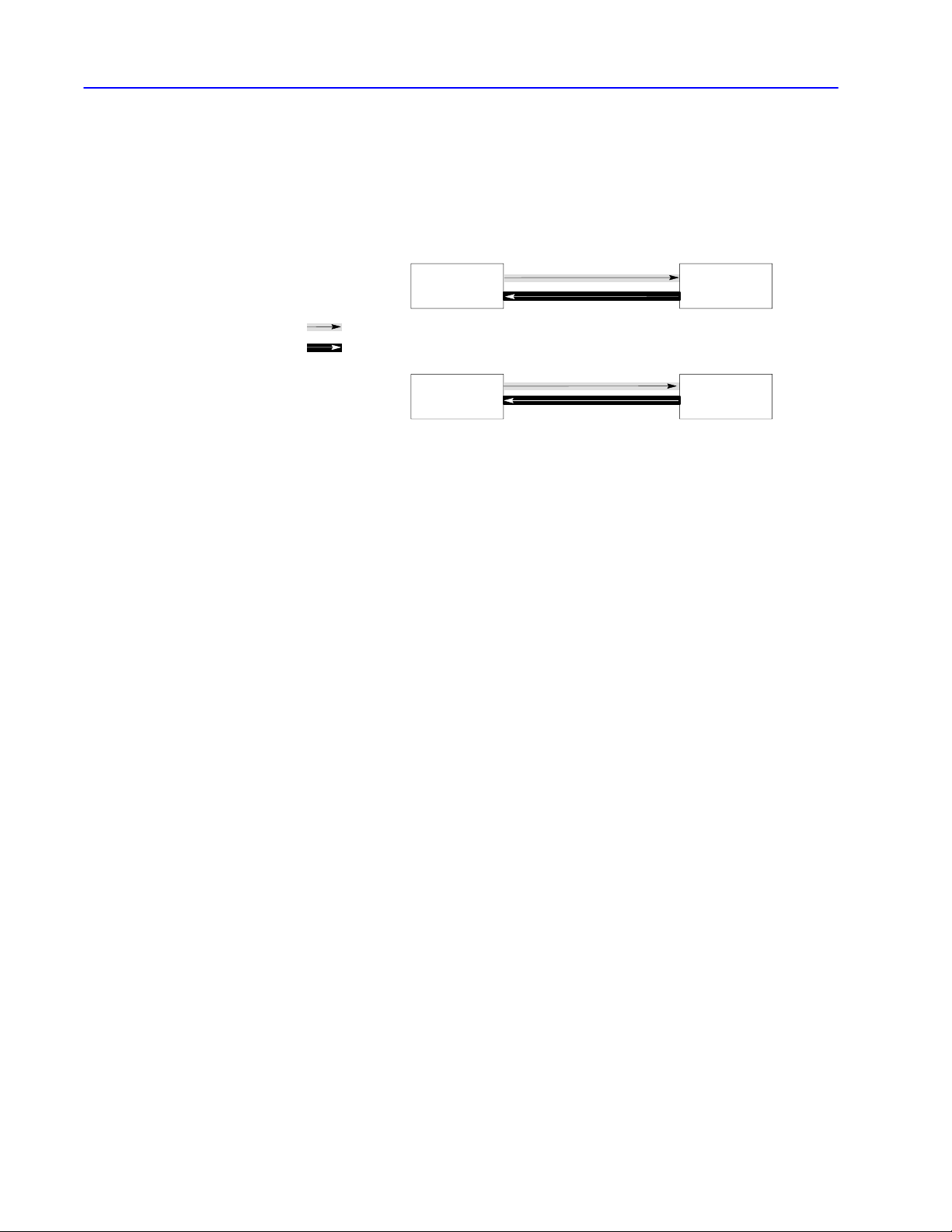
4–2 Using Full-duplex Protocol to Send and Receive Messages
Fullduplex Protocol
Message Transmission
circuit 1
circuit 2
With full-duplex protocol, a link uses two physical circuits for
two-way simultaneous message transmission (command or reply
message packets). These two physical circuits provide
communication on four logical paths:
Figure 4.1
Data paths for twoway simultaneous operation
path 1
transmitter A
path 2
path 3
path 4
•On the first circuit, transmitter A sends messages to receiver B (path 1) and receiver A sends response
control symbols (DLE ACK, DLE NAK) to transmitter B (path 3).
•On the second circuit, transmitter B sends messages to receiver A (path 4) and receiver B sends
response control symbols (DLE ACK, DLE NAK) to transmitter A (path 2).
•All message and symbols on the first circuit are traveling in the same direction (node A to node B) and all
messages and symbols on the second circuit are traveling in the opposite direction (B to A).
receiver B
transmitter Breceiver A
Publication
17706.5.16 - October 1996
Page 57

Figure 4.2
Software implementation of data paths
Paths 1, 2, 3, and 4
4–3Using Full-duplex Protocol to Send and Receive Messages
Transmitter A
Path 2
Software
Separator
Receiver A
Paths 1 (a message symbol sent from node A to node B)
•To implement four logical paths with two physical circuits, a software multiplexer is needed to combine the message symbols with
the response symbols going in the same direction.
•At the other end of the link, a software separator divides the message symbols from the response symbols.
The internal software sends the message symbols to the appropriate receiver, and the response symbols to the appropriate
transmitter.
•Although message symbols and response symbols on the same circuit operate independently of each other,
there is some interaction.
•For example, a message on physical circuit AB will be delayed if a response symbol from receiver A is inserted in a stream of
message symbols from transmitter A (embedded response).
•Also, any hardware problems that affect message symbols traveling over a circuit will also affect response symbols
on the same circuit.
Path 1
Software
Multiplexer
Physical Circuit BA
Path 3 Path 4Path 4 Path 3
Transmitter A
Path 1
Software
Multiplexer
Physical Circuit AB
Physical Circuit
Receiver B
Path 2
Software
Multiplexer
Transmitter B
Path 1
Software
Separator
Receiver B
Path 1
Software
Separator
Fullduplex Protocol
Environment
To define the environment of the protocol:
• the transmitter needs to know where to get the message it sends,
the message source. We assume the message source:
– supplies one message at a time upon request from the
transmitter
– requires notification of the success or failure of the transfer
before supplying the next message
• the receiver must have a means of disposing of messages,
the message sink
If the Then the
message source is empty
receiver has received a message
successfully
transmitter waits in an inactive state until a
message is available
receiver attempts to give it to the message
sink. If the message sink is full, the
receiver must be notified
Publication
17706.5.16 - October 1996
Page 58

4–4 Using Full-duplex Protocol to Send and Receive Messages
Figure 4.3 shows the protocol environment for message symbols
from transmitter A to receiver B (path 1) and response codes from
receiver B to transmitter A (path 2).
Figure 4.3
Protocol Environment
Packet
Transmitter A SinkReceiver BSource
Path 1
Path 2
Packet
Sink FullPacket Status
Message Characteristics
Ideally, the data-link-layer protocol is not concerned with the content
or form of the message packet (link-layer data) it is transferring.
However, full-duplex protocol places the following restrictions on
link-layer data submitted to it for transfer:
• minimum size of valid link-layer data is 6 bytes
• maximum size of valid link-layer data depends on the
application-layer command
• some protocol implementations (e.g., point-to-point links to a
1771-KG module) require that the first byte of the link-layer data
match the node address
The receiver ignores messages that do not contain the correct
address.
• as part of the duplicate message detection algorithm, the receiver
compares the second, third, fifth, and sixth bytes of the link-layer
data with the same bytes in the previous message
If there is no difference between the sets of bytes, the message is
classified as a re-transmission of the previous message. You can
set some Allen-Bradley interface modules so that they do not
implement duplicate-message detection.
Transmitter and Receiver
Message
Publication
Transfer
17706.5.16 - October 1996
In full-duplex protocol, messages are sent from the source (part of
software that supplies message packet) through a transmitter
(device that sends data) and then a receiver (device that receives
data) to the sink (part of the software that accepts the received data):
For See page
structured text on how the transmitter operates 4-5
a flowchart of how the transmitter operates 4-6
structured text on how the receiver operates 4-7
a flowchart of how the receiver operates
4-9
Page 59

How the Transmitter Operates
The following program describes the actions of the transmitter:
Whenever the message source can supply a message packet and the
transmitter is not busy
address. It then starts a timeout, and waits for a response.
When this response is The message packet
received from the receiving
address
DLE ACK
DLE NAK
If the timeout expires before a response is received, the transmitter sends
a DLE ENQ to request a retransmission of the last response. It restarts
the timeout and waits for a response.
Y
ou can also set a limit to the number of timeouts that are allowed per
message. If the enquiry (ENQ) limit is exceeded, the transmitter signals
the message source that the transmission has failed, and the transmitter
proceeds to the next message.
There are three responses defined: DLE ACK, DLE NAK, DLE ENQ,
If the transmitter receives an different response, the transmitter ignores it.
, it sends a frame on the link to the destination
has been successfully transferred.
After signaling the message
source that the message packet
was successfully transmitted, the
transmitter proceeds with the next
message packet.
is retransmitted. The transmitter
restarts the timeout and waits
again for a response. If it receives
a DLE ACK, the transmitter starts
a timeout.
This can be repeated several
times. You can set a limit to the
number of times a message can
be retransmitted for each module.
If this limit is exceeded, the
message source is informed of the
failure and the transmitter
proceeds with the next message.
TRANSMITTER is defined as
loop
Message=GET-MESSAGE-TO-SEND
Status=TRANSFER(Message)
SIGNAL-RESULTS(Status)
end loop
loop
WAIT for response on path 2 or timeout.
if received DLE ACK then return SUCCESS
else if received DLE NAK then
if nak-limit is exceeded then return FAILURE
else
begin
count NAK re-tries;
SEND-MESSAGE(message);
start timeout
end
else if timeout
if enq-limit is exceeded then return FAILURE
else
begin
count ENQ re-tries;
send DLE ENQ on path 1;
start timeout
end
end loop
SEND (message) is defined as
begin
BCC = 0
send DLE STX on path 1
for every byte in the message do
begin
add the byte to the BCC;
send the corresponding data symbol
on
path 1
end
send DLE ETX BCC on path 1
end
GET-MESSAGE-TO-SEND
This is an operating-system-dependent interface
routine that waits and allows the rest of the
system to run until the message source has supplied
a message to be sent.
SIGNAL-RESULTS
This is an implementation-dependent routine that
tells the message source of the results of the
attempted message transfer.
WAIT
This is an operating-system-dependent routine
that waits for any of several events to occur
while allowing other parts of the system to run.
TRANSFER (Message) is defined as
initialize nak-limit and enq-limit
SEND(Message)
start timeout
4–5Using Full-duplex Protocol to Send and Receive Messages
Publication
17706.5.16 - October 1996
Page 60

4–6 Using Full-duplex Protocol to Send and Receive Messages
The following flowcharts the software logic for implementing the
transmitter:
Legend:
= Ready to transmit next message
T
= Recovery procedure
P
= Default values used by the module
*
T
message frame
DataDLE STX DLE ETX
Received
DLE
ACK?
No No
Yes Ye s Yes
T
retransmit same message
BCC/CRC
Field
timeout loop
Received
DLE
NAK?
3* NAKs
received
for this
message?
Yes Yes
P
No No
Timed
out?
3* ENQ
sent?
DLE ENQ
No
Important: Depending on network-link traffic and saturation level,
you may need to wait for a reply from the remote node
before transmitting the next message. Implement an
option that allows users to choose the maximum amount
of outstanding messages that can exist at one time;
we suggest a selectable range of one to three messages.
Publication
17706.5.16 - October 1996
Page 61

4–7Using Full-duplex Protocol to Send and Receive Messages
How the Receiver Operates
The receiver must be capable of responding to adverse situations.
Some of the problems that can occur are:
• the message sink is full, so the receiver has nowhere to put
a message
• a message can contain a parity error
• the BCC or CRC can be invalid
• the DLE STX or DLE ETX BCC/CRC may be missing
• the message is too long or too short
• a false control or data symbol occurs outside a message
• a false control symbol occurs inside a message
• the DLE ACK response is lost, causing the transmitter to send a
duplicate copy of a message already passed to the message sink
Publication
17706.5.16 - October 1996
Page 62

4–8 Using Full-duplex Protocol to Send and Receive Messages
The following program describes the actions of the receiver in detail.
The receiver keeps a record of the last response sent to
the transmitter
ACK or DLE NAK. It is initialized to DLE NAK. When a
DLE ENQ (enquiry) is received from the transmitter
receiver sends the value of the last response.
The receiver ignores all input until a DLE STX or DLE ENQ
is received. If anything other than a DLE STX or DLE ENQ
is received on path one, the receiver sets the last response
variable to NAK.
When this symbol is received Then the
from the transmitter
DLE ENQ
DLE ACK
While building a reply message, all data symbols are
stored in the message buf
If the buf
BCC/CRC, but the data is discarded.
If a parity, overrun, framing, or modem handshaking error is
detected, it is recorded .
If a control symbol other than DLE STX or DLE ETX is
received, the message is aborted and a DLE NAK is sent
to the transmitter
the error flag, the BCC/CRC, the message size, and the
address (optionally) are all checked. If any of the tests fail,
a DLE NAK is sent.
GET
function that returns one byte of data from the link
interface hardware
. The value of this response is either DLE
, the
last response is sent
and the receiver
continues waiting for
input.
BCC/CRC and the
message buf
reset, and the receiver
starts building a reply
message.
fer and added to the BCC/CRC.
fer overflows, the receiver continues summing the
. When DLE STX or DLE ETX is received,
CHAR is defined as an implementationdependant
fer are
RECEIVER
GET
end
else return char with a control flag
is defined as
variables
LAST
-HEADER is 4 bytes copied out of the last good message
RESPONSE is the value of the last ACK or NAK sent
BCC is an 8-bit block check accumulator
LAST-HEADER = invalid
LAST RESPONSE = NAK
loop
reset parity error flag
GET-SYMBOL
if DLE STX then
begin
BCC = 0
GET-SYMBOL
while it is a data symbol
begin
if buf
data in buf
GET-SYMBOL
end
if the control symbol is not a DLE ETX then send DLE
NAK
else if error flag is set then send DLE NAK
else if BCC is not zero then send DLE NAK
else if message is too small then send DLE NAK
else if message is too large then send DLE NAK
else if header is same as last message send a DLE ACK
else if message sink is full send DLE NAK
else
begin
send message to message sink
send a DLE ACK
save a last header
end
else if DLE ENQ then send LAST
else LAST
end loop
-SYMBOL is defined as
loop
GET-CHAR
if char is not DLE
else
GET-CHAR
add char to BCC
return ETX with a control flag
end loop
end
-RESPONSE = NAK
begin
add char to BCC
return the char and data flag
end
begin
GET-CHAR
if char is a DLE
begin
add char to BCC
return DLE and data flag
end
else if char is an ACK or NAK send it to the transmitter
else if char is an ETX
begin
end
fer is not overflowed put
fer
-RESPONSE
Publication
17706.5.16 - October 1996
Page 63

The following flowchart is the software logic for implementing the
receiver.
RCVE
LAST = NAK
4–9Using Full-duplex Protocol to Send and Receive Messages
No
Received
DLE
ENQ?
No
Received
message?
Yes
BCC/
CRC
OK?
Yes
LAST = ACK
Yes
No
LAST = NAK
Send DLE LAST
Publication
17706.5.16 - October 1996
Page 64

4–10 Using Full-duplex Protocol to Send and Receive Messages
Fullduplex Protocol
Diagrams
These transfer diagrams show events that occur on various
interfaces. Time is represented as increasing from the top of the
diagram to the bottom. Link-layer data bytes are represented by
“xxxx” and corrupted data by “???”.
For this diagram See page
normal message transfer 4-10
message transfer with NAK 4-11
message transfer with timeout & ENQ 4-12
message transfer with retransmission 4-13
message transfer with message sink full 4-14
message transfer with NAK on reply 4-15
message transfer with timeout and ENQ for the reply 4-16
message transfer with message source full on the reply
4-17
Normal Message Transfer
In this transfer:
• the transmitter sends the data to the receiver
• the sink sends a “not full” message
• the receiver sends the data to the sink and sends a DLE ACK to
the transmitter
• the transmitter tells the source that the data was delivered
• reply is successfully returned
Source Transmitter Link Receiver Sink
command
reply
xxxx
OK
(sometime later ...)
not full
xxxx
DLE STX xxxx DLE ETX BCC/CRC
not full
xxxx
DLE ACK
DLE STX xxxx DLE ETX BCC/CRC
DLE ACK
OK
Publication
17706.5.16 - October 1996
Page 65

4–11Using Full-duplex Protocol to Send and Receive Messages
Message Transfer with NAK
In this transfer:
• the transmitter sends corrupted data to the receiver and the
receiver responds with a DLE NAK
• the transmitter retransmits and the transmission is successful
• the receiver sends a DLE ACK to the transmitter
• reply is successfully returned
Source Transmitter Link Receiver Sink
command
xxxx
OK
DLE STX x???x DLE ETX BCC/CRC
DLE NAK
DLE STX xxxx DLE ETX BCC/CRC
not full
xxxx
DLE ACK
reply
(sometime later ...)
DLE STX xxxx DLE ETX BCC/CRC
not full
xxxx
DLE ACK
OK
Publication
17706.5.16 - October 1996
Page 66

4–12 Using Full-duplex Protocol to Send and Receive Messages
Message Transfer with Timeout and ENQ
In this transfer:
• the receiver receives a transmission, but sends back a
DLE ACK that is corrupted
• the transmitter times out waiting for the DLE ACK and sends a
DLE ENQ
• the receiver sends back a DLE ACK
• a reply is successfully returned
Source Transmitter Link Receiver Sink
command
xxxx
DLE STX xxxx DLE ETX BCC/CRC
(timeout)
OK
(sometime later ...)
reply
DLE STX xxxx DLE ETX BCC/CRC
not full
xxxx
not full
xxxx
DL???CK
DLE ENQ
DLE ACK
DLE ACK
OK
Publication
17706.5.16 - October 1996
Page 67

4–13Using Full-duplex Protocol to Send and Receive Messages
Message Transfer with ReTransmission
In this transfer:
• noise destroys the DLE ACK while also producing invalid
characters at the receiver
• because of the invalid characters, the receiver changes its last
response variable to a DLE NAK
• since the DLE ACK was destroyed, the transmitter sends a DLE
ENQ (enquiry), and the receiver returns the DLE NAK
• the transmitter retransmits the message and the receiver sends an
ACK
• the receiver discards the duplicate message (if duplicate message
detection is enabled on your module)
• reply is successfully returned
Source Transmitter Link Receiver Sink
command
xxxx
(timeout)
(timeout)
DLE STX xxxx DLE ETX BCC/CRC
not full
xxxx
DL???CK
???
DLE ENQ
DLE NAK
reply
OK
(sometime later ...)
not full
xxxx
DLE STX xxxx DLE ETX BCC/CRC
DLE ACK
DLE STX xxxx DLE ETX BCC/CRC
DLE ACK
(duplicate message)
In this transfer, the receiver has no way of knowing that the DLE
ACK it sent to the transmitter was destroyed. If the transmitter’s
ACK timeout is large enough, it is possible that the reply
(i.e., DLE STX xxxx DLE ETX BCC/CRC) comes back before the
transmitter sends the DLE ENQ. Therefore, the reply comes in
before the DLE ACK is received by the transmitter.
OK
Publication
17706.5.16 - October 1996
Page 68

4–14 Using Full-duplex Protocol to Send and Receive Messages
Message Transfer with Message Sink Full
In this transfer:
• the transmitter sends a message but the message sink is full,
so the receiver sends back a DLE NAK
• the transmitter retransmits and the sink is no longer full,
so the receiver returns a DLE ACK
• a reply is successfully returned
Source Transmitter Link Receiver Sink
command
xxxx
OK
(sometime later ...)
reply
not full
xxxx
DLE STX xxxx DLE ETX BCC/CRC
DLE STX xxxx DLE ETX BCC/CRC
DLE STX xxxx DLE ETX BCC/CRC
DLE STX xxxx DLE ETX BCC/CRC
Full
DLE NAK
Full
DLE NAK
not full
xxxx
DLE ACK
DLE ACK
OK
Publication
17706.5.16 - October 1996
Page 69

4–15Using Full-duplex Protocol to Send and Receive Messages
Message Transfer with NAK on Reply
In this transfer:
• the message is successfully transmitted on the network
• the reply is corrupted and the transmitter responds with a DLE
NAK
• the reply is sent again and is successful
Source Transmitter Link Receiver Sink
command
xxxx
OK
(sometime later ...)
reply
not full
xxxx
DLE STX xxxx DLE ETX BCC/CRC
DLE ACK
DLE STX x??x DLE ETX BCC/CRC
DLE NAK
DLE STX xxxx DLE ETX BCC/CRC
DLE ACK
not full
xxxx
OK
Publication
17706.5.16 - October 1996
Page 70

4–16 Using Full-duplex Protocol to Send and Receive Messages
Message Transfer with Timeout and ENQ for the Reply
In this transfer:
• the message is successfully transmitted on the network
• the receiver sends a reply from the network but the transmitter
sends back a DLE ACK that is corrupted
• the receiver times out waiting for the DLE ACK and sends a DLE
ENQ
• the transmitter sends back a DLE ACK
Source Transmitter Link Receiver Sink
command
xxxx
DLE STX xxxx DLE ETX BCC/CRC
OK
(sometime later ...)
DLE ACK
not full
xxxx
reply
DLE STX xxxx DLE ETX BCC/CRC
not full
xxxx
DL???CK
(Timeout)
DLE ENQ
DLE ACK
OK
Publication
17706.5.16 - October 1996
Page 71

Message Transfer with Message Source Full on the Reply
In this transfer:
• the message is successfully transmitted on the network
• the receiver sends a reply but the message source is full,
so the transmitter sends back a DLE NAK
• the receiver retransmits and the source is no longer full,
so the transmitter returns a DLE ACK
Source Transmitter Link Receiver Sink
command
reply
xxxx
OK
(sometime later ...)
Full
DLE STX xxxx DLE ETX BCC/CRC
DLE ACK
DLE STX xxxx DLE ETX BCC/CRC
not full
xxxx
4–17Using Full-duplex Protocol to Send and Receive Messages
not full
xxxx
DLE NAK
DLE STX xxxx DLE ETX BCC/CRC
DLE ACK
OK
Publication
17706.5.16 - October 1996
Page 72

Message Packets
Datalink Layer Message Frames Chapter 5
Application Layer Message Packets Chapter 6
Communication Commands Chapter 7
Message Packet Status Codes (STS and EXT STS)
Chapter 8
Page 73

Chapter 5
Datalink Layer Message
Frames
In the data-link layer of a message frame:
• half-duplex protocol uses three types of message transmission
• full-duplex protocol implements its message fields at different
network layers
• at the end of each polling and message frame, there is a one-byte
BCC field or a two-byte CRC field
Read this chapter to help learn the fields that your computer uses in
the data-link layer of a message frame. It contains these sections:
Section Page
Halfduplex Protocol Message Frames 5-2
Fullduplex Protocol Message Frames 5-3
BCC and CRC Fields
5-4
Publication
17706.5.16 - October 1996
Page 74

5–2 Data-link Layer Message Frames
Halfduplex Protocol
Message Frames
Half-duplex protocol uses three types of transmissions:
• polling frame
• master message frame
• slave message frame
The master node transmits both polling frames and master message
frames, and slave nodes transmit slave message frames.
The following figure illustrates the formats of these frames.
The slave message frame has the same format as the full-duplex
message frame. The master message frame is the same as the slave
message frame except that it is prefixed with DLE SOH and an
address to specify a slave station address (STN).
Important: Even if you set your module to use CRC, when you
send a polling frame, it uses a single BCC byte.
Polling Frame
BCCENQDLE STN
Master Message Frame
From common application routines
CMD STSSRC TNSDLE DSTSTXDLE SOH STN
Data
(command
data)
DLE ETX
BCC/
CRC
Slave Message Frame
CMD STSSRC TNSDLE DSTSTX
From common application routines
The BCC field contains the 2's complement of the 8bit sum (module256 arithmetic sum) of the slave station address
(STN) and all the data bytes in the frame. For polling frames, the BCC is simply the 2's complement of STN. The BCC
does not include any other message frame symbols or response symbols.
Data
(command data)
DLE ETX
BCC/
CRC
Publication
17706.5.16 - October 1996
Page 75

5–3Data-link Layer Message Frames
Fullduplex Protocol
Message Frames
From user application program
From common application routines
Datalink layer frame
Full-duplex protocol implements different message frames,
depending on the network layer. This figure shows the format of a
message frame for full-duplex protocol and the layer at which each
portion is implemented:
DST CMD STS
DST CMD STSSRC
DLE STX DLE ETX
The
BCC/CRC field contains the 2'
application layer data bytes between the DLE STX and the DLE ETX BCC. It does not include any
response symbols. Y
• block check character (BCC)
• 16bit cyclic redundancy check (CRC16)
data from
application layers
ou can use the BCC/CRC field for one of the following types of error checking:
TNS
s complement of the 8bit sum (module256 arithmetic sum) of all
command data
data
(from application layer)
BCC/CRC
field
Publication
17706.5.16 - October 1996
Page 76

5–4 Data-link Layer Message Frames
BCC and CRC Fields
At the end of each polling frame and each message frame, there is
a one-byte BCC (block check character) field, or a two byte CRC
(cyclic redundancy check) field. You select BCC or CRC through
switch settings or software configuration. Either field allows you to
verify the accuracy of each message frame transmission:
• The BCC algorithm provides a medium level of data security:
– it cannot detect transposition of bytes during transmission
of a frame
– it cannot detect the insertion or deletion of the value zero
within a frame
• The CRC field provides a higher level of data security than BCC
but is more difficult to implement
BCC Field
We’ve included both half- and full-duplex BCC examples:
Half-duplex protocol example
If the master node wants to send the hexadecimal data symbols 08, 09, 06, 00, 10, 04, and
03 to slave node 20
10 01 20 10 02 08 09 06 00 10 10 04 03 10 03 B2
STN DLE STX APP DATA (DLE DLE) DLE ETX BCC
(40 octal), the master message symbols are:
16
The sum of the STN and application layer data bytes in this message frame is 4E
The BCC is the 2's complement of this sum, or B216. This is shown in the following binary
calculation:
0100 1110 = sum (4E
1011 0001 = 1's complement
+1
1011 0010 2's complement (B2
To transmit the STN or data value 10 hex, you must use the data symbol DLE DLE.
You must also use the data symbol DLE DLE if your STN value is 10. Only one of these
DLE bytes, however, is included in the BCC sum.
For example, to transmit the data values 08, 09, 06, 00, 10, 04, and 03 (hex), a slave node
uses the following message symbols:
10 02 08 09 06 00 10 10 04 03 10 03 D2
DLE STX APP DATA (DLE DLE) DLE EXT BCC
In this case, the sum of the data bytes is 2E hex because only one DLE byte is included in
the BCC. The BCC (2's complement) of 2E
)
16
= BCC)
16
is D216.
16
.
16
Publication
17706.5.16 - October 1996
Page 77

Full-duplex protocol example
If a message frame contained the data 08. 09, 06, 00, 02,04, and 03 (decimal),
the message symbols are:
10 02 08 09 06 00 02 04 03 10 03 E0
DLE STX APP DATA DLE ETX BCC
The sum of the application data bytes in this message frame is 32 decimal or 20 hex.
The BCC is the 2's complement of this sum, or E0 hex. This is shown in the following
binary calculation:
0010 0000 20
1101 1111 1's compliment
+1
1110 0000
To quickly determine a BCC value, add up the hex values of the application layer bytes.
If the total is greater than 100 hex, drop the most significant digit. Then, subtract the result
from 100 hex. This gives you the BCC. For example, if the sum of the application layer
bytes is 20 hex, then:
100
16
-20
16
____
E0
16
Important: To transmit the value 10 hex, you must use the data symbol DLE DLE.
16
2's compliment (E0 hex)
However, only one of these DLE data bytes is included in the BCC sum.
For example, to transmit the values 08, 09, 06, 00, 10, 04, and 03 hex, use
the following message symbols:
5–5Data-link Layer Message Frames
10 02 08 09 06 00 10 10 04 03 10 03 D2
DLE STX APP DATA (DLE DLE) DLE EXT BCC
In this case, the sum of the application layer data bytes is 2E hex because only one DLE
byte is included in the BCC. So the BCC is D2
. This is sometimes referred to as
16
doublestuffing" DLEs.
Important: If your BBC check sum is 10 hex, send it as “10” and
not “10 10.” That is, a BCC is not treated like data.
Publication
17706.5.16 - October 1996
Page 78

5–6 Data-link Layer Message Frames
CRC Field
For these protocols
fullduplex using the value of the linklayer data bytes and the ETX byte.
halfduplex
➀
The polynomial for a CRC value is:
➁
Do not add in the associated DLE for STX and ETX values.
You calculate the CRC value
•for master messages using the value of the linklayer data
bytes and the STN, STX and ETX bytes
•for slave messages using the value of the linklayer data bytes
and the ETX byte
X16 + X15 + X2 + X0.
➀
➁
Important: To transmit the data value of 1016, you must use the
data symbol DLE DLE. However, only one of these
DLE bytes is included in the CRC value.
Embedded responses are not included in the CRC value.
The following explains the transmission of the CRC value:
1. At the start of a message frame, the transmitter clears a 16-bit
register used for the CRC value.
2. As a byte is transmitted, it is exclusive-ORed (least-significant bit
to the right) with the right eight bits of the CRC register.
3. The result is placed in the right eight bits of the CRC register.
4. The CRC register is then shifted right eight times by inserting 0s
on the left. Each time a 1 is shifted out on the right, the CRC
register is exclusive-ORed with this 16-bit constant:
1010
0000 0000 0001
5. As each additional byte is transmitted, it is included in the value
in the register the same way.
6. After the ETX value is transmitted, the value in the CRC register
is transmitted (right bit first). The receiver also calculates the
CRC value and compares it to the received CRC value to verify
the accuracy of the data received.
Publication
17706.5.16 - October 1996
Page 79

5–7Data-link Layer Message Frames
The full-duplex and half-duplex slave and master protocol examples
below provide you with procedures for determining the CRC-16
value.
Full-duplex and half-duplex slave protocol
data_byte = all linklayer data, ETX
CLEAR CRC_REGISTER
FOR each data_byte
GET data_byte
XOR (data_byte, right eight bits of CRC_REGISTER)
PLACE RESULT in right eight bits of CRC_REGISTER)
DO 8 times (on CRC register_
Shift bit right, shift in 0 at left
IF bit shifted = 1
XOR (CONSTANT, CRC_REGISTER)
PLACE RESULT in CRC_REGISTER
END IF
END DO
END FOR
TRANSMIT CRC_REGISTER as 2byte CRC field (low byte, high byte)
Half-duplex master protocol
data_byte = STN, STX, all linklayer data, ETX
CLEAR CRC_REGISTER
For each data_byte
GET data_byte
XOR (data_byte, right 8 bits of CRC_REGISTER)
PLACE RESULT in right 8 bits of CRC_REGISTER
DO 8 times
Shift bit right, shift in 0 at left
IF bit shifted = 1
XOR (CONSTANT, CRC_REGISTER)
PLACE RESULT in CRC_REGISTER
END IF
END DO
END FOR
TRANSMIT CRC_REGISTER as 2 byte CRC field
Below is an actual frame that you can use to validate your CRC
routine:
Use this frame to validate the CRC
53 B911 004110 02 07 00 00 00 00 00 00 00 00 00 00 00 00 10 03 6B 4C
Publication
17706.5.16 - October 1996
Page 80

Chapter 6
Application Layer Message
Packets
Read this chapter to help learn about the application layer for your
asynchronous driver and the fields that your computer uses in the
application layer of a message packet. It contains these sections:
Section Page
How Your Application Program Sends and Receives Messages 6-2
Message Packet Format 6-3
Publication
17706.5.16 - October 1996
Page 81

6–2 Application Layer Message Packets
application
How Your Application Program Sends and Receives Messages
There are two types of application programs:
• command initiators
• command executors
This application program Sends
command messages - specify which command function
to execute at a particular remote node
Each command message requires one reply message.
The command initiator must check for error codes and,
command initiator
command executor
Internally, Allen-Bradley asynchronous interface modules use a
routing subroutine and a message queue. When the module receives
a message over its asynchronous link, it puts the message in its
queue. The routing subroutine then takes the message from the
queue and transmits it over the DH, DH+, or DH485 network.
The module also queues messages received from the network.
The routing subroutine takes these messages and retransmits them
over the asynchronous link.
depending on the type of error, retransmit the message or
notify the user.
The command initiator should also use a timer to be aware
of lost reply messages (due to noise or other factors).
If the time limit expires before the initiator receives the
reply, the initiator can retransmit or notify the user.
reply messages - responsible for interpreting and
executing the command message.
The executor must issue a reply message for each
command it receives. If the executor cannot execute a
command, it must send the appropriate error code.
If this layer Cannot deliver a It should
generate a reply message with the
application
datalink
command message
reply message
message over the
asynchronous link
appropriate error code and send the reply to
the initiator.
destroy the reply without notification to the
command executor.
return an error message to the command
initiator.
Publication
17706.5.16 - October 1996
Page 82

6–3Application Layer Message Packets
Message Packet Format
Most devices send and receive messages using this message
packet format:
Command
Reply
The bytes are shown from left to right in the order they are transmitted across the link.
Field Contents See
DST destination node for the message
SRC source node of the message
FNC function code
CMD command code
ADDR address of memory location (2 bytes) page 6-8
STS status code
EXT STS extended status code
SIZE number of bytes to be transferred page 6-8
TNS transaction number (2 bytes) page 6-7
DATA
DST CMD STS
SRC
SRC CMD STS
read
write
DST TNS
SRC CMD STSDST TNS
data values being transferred by the message
The number of data bytes in a message depends on
the command or function being executed.
TNS
Commandspecific
packet
data
ADDR
FNC
Commandspecific
data packet
SIZE DATA
page 6-4
page 6-5
page 6-6
Chapter 7
The combination of SRC, CMD, and TNS bytes uniquely identifies
every message packet. One of these fields in the current message
must be different than the corresponding field in the last message
received by a command executor. If all fields are the same, the
message is ignored and is considered to be a duplicate. If the
receiving module has the “ignore duplicate messages” option
enabled, the message will be ignored.
Publication
17706.5.16 - October 1996
Page 83
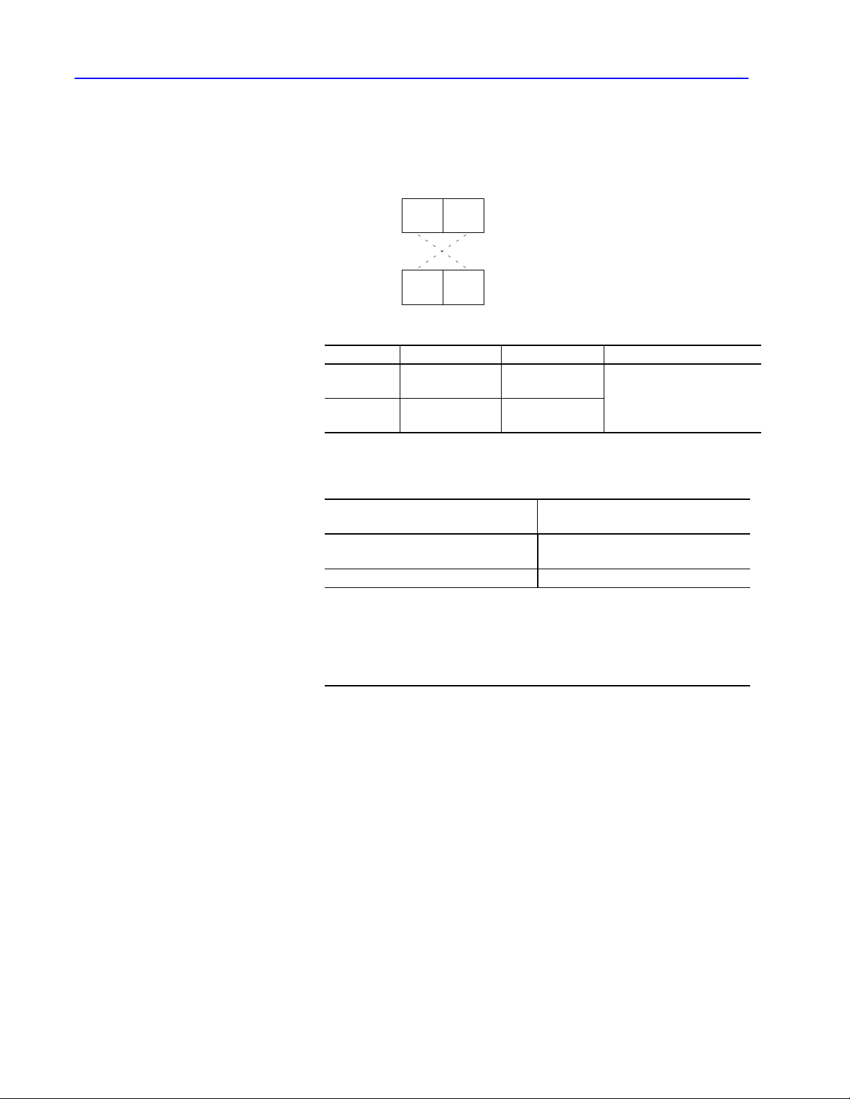
6–4 Application Layer Message Packets
•0
376 (octal) for DH
DST and SRC
Form the DST and SRC bytes of a reply message by interchanging
the DST and SRC bytes of the corresponding command message:
Command
Reply
DST SRC
SRC DST
Byte Contents Value supplied by Value range
DST
(destination)
SRC
(source)
receiving message application layer
sending message data link layer
•0 to 376 (octal) for DF1
•0 to 376 (octal) for DH
to
•0 to 77 (octal) for DH+
•0 to 31 (decimal ) for DH485
When sending messages from asynchronous devices, special
consideration must be given to the SRC byte:
When sending a message from an
asynchronous device connected
to the network
➀
directly to a 1771KG
➀
If
you connect to channel 0 of a PLC5/1
send a PLC2
you put into the SRC byte is very important. This determines the compatibility file. This means
that the value of the SRC byte specifies the data table file number that is written to the PLC5
processor
compatibility file is always 9.
unprotected write, protected write, protected bit write,
. The source byte will not be overwritten by channel 0. For SLC 500 processors, the
Set the SRC byte
= 0 (the module will set the byte to its own
node number)
10 (octal)
1, 5/20, 5/30, 5/40, 5/60 or 5/80 processor and you
or
unprotected bit write,
what
Publication
17706.5.16 - October 1996
Page 84

CMD and FNC
see table that begins on
These bytes work together to define the activity that is to be
performed by the command message at the destination node.
Values for these bytes are supplied by the application layer.
The message format depends on the CMD and FNC values.
CMD byte
Bit: 7 6 5 4 3 2 1 0
Command
0
or Reply
Priority
0
Command
6–5Application Layer Message Packets
always = 0 always = 0
command message = 0
reply message = 1
➀
High
priority only applies to DH links. It does not apply to DH+, DH485, or DHII links.
This byte Defines the And has these values
CMD
(command)
FNC
(function)
Example
PLC2 command e
send =
reply =
command type
specific function under that command type
code
nter download mode
00000111
01000111 (
(07 hex)
47 hex)
highpriority send (DH only) =
highpriority
reply (DH only) =
normal priority = 0
high priority= 1
0010011
1
01100111 (67 hex)
27
hex
command code
➀
see table that begins on
page 7-2
Publication
17706.5.16 - October 1996
Page 85

6–6 Application Layer Message Packets
STS and EXT STS
These bytes work together to indicate the status of the message
transmission.
This byte In this message Has this value
STS
(status)
EXT STS
(extended status)
➀
EXT STS is part of the message only if STS = F0.
command The application program sets = 0.
reply
= 0 when the command has executed with no
error.
= one of the status codes listed in Chapter 8,
➀
reply
Message Packet Status Codes (STS, EXT
STS)." This byte will also 0 if an error
occurs.
Four high bits
of STS byte all
= 1 (F0 hex)?
No
no EXT STS byte
Application layer uses these bits (and in some cases the EXT STS byte),
to report remote errors errors that occur when the command executor
at the destination node tries to execute the command message).
Yes
EXT STS byte
"
STS byte
STS and EXT STS error codes
For more information on STS and EXT STS error codes,
see Chapter 8, “Message Packet Status Codes (STS, EXT STS).”
32107654
Link layer uses these bits to report local errors errors that occur
when the link layer attempts to transmit a message across the link.
Publication
17706.5.16 - October 1996
Page 86

6–7Application Layer Message Packets
TNS
The TNS (transaction) bytes contain a unique 16-bit transaction
identifier. Generate this number by maintaining a 16-bit counter.
Increment the counter each time your command initiator (application
program) creates a new message, and store the counter value in the
two TNS bytes of the new message. In a multi-tasking environment,
you must use only one TNS counter, and the procedure to read and
increment the TNS must be indivisible.
command
reply
For command messages
transmitted by
a PLC the interface module assigns the TNS values.
computer node
TNS
TNS
Command executor copies the TNS field of the command message into
the TNS field of the corresponding reply message.
Command
command messages. The low byte (least significant bits) of the TNS value
is transmitted before the high byte (most significant bits).
initiator checks TNS value of reply and matches it to one of its
Values are assigned by
your application level software. The software must
assign a unique 16bit transaction number.
Important: Do not change the TNS value in a reply message.
If you change this value, the command initiator cannot
match its command to the corresponding reply message.
Publication
17706.5.16 - October 1996
Page 87

6–8 Application Layer Message Packets
ADDR
The ADDR (address) bytes contain the byte address of a memory
location in the command executor where the command is to begin
executing, except in SLC 500 processors, where the ADDR byte is
interpreted as the word address.
In SLC 5/02, SLC 5/03, and SLC 5/04 processors, the CIF
Addressing Mode bit, S:2/8, can be set to a one to change the
interpretation of the ADDR byte to the byte address, so that it is
compatible with other PLC processors. For example, if the
command is to read data from the command executor, ADDR
specifies the address of the first byte of data to be read.
the low (least significant) byte of the address contains the high byte of the address
contains
ADDR
"
Sending commands to PLC-3, PLC-5, and SLC 500 processors
In some instances, when sending commands from the basic
command set to a PLC-3, PLC-5, or PLC-5/250 processor, or to an
SLC 500 processor, you must create special files to accept the data.
Important: The ADDR field specifies a byte address, not a word
address as in PLC data tables. Chapter 13, “PLC
Addressing,” explains how to convert PLC word
addresses to byte addresses. Also, if you use the
“native” read and write commands in PLC-3, PLC-5, or
SLC 500 processors, the address is not a byte address; it
is a logical binary, logical ASCII, or SLC address with
multiple address fields.
SIZE
The SIZE byte specifies the number of data bytes to be transferred
by a message. This field appears in read commands, where it
specifies the number of data bytes that the responding node must
return in its reply message.
Publication
The SIZE varies with the type of command. For PLC-5 and
PLC-5/250 typed read and typed write commands, the SIZE field
specifies the number of elements, not bytes. In PLC-5 typed read
and typed write commands, the SIZE field is two bytes long
—transmit low byte first and high byte second.
17706.5.16 - October 1996
Page 88

Chapter 7
Communication Commands
This chapter contains the format you should use when sending
communication commands to Allen-Bradley processors.
Use this key to help learn the conventions that depict the
communication commands listed in this chapter:
• PLC3
processors that can
use the command
command
command
format
command name
This text describes how the command is used.
command code function code
C
reply
format
R
Unless otherwise stated, values are shown in hexadecimal.
"
CMD
Message packets
The message packets for these commands include STS and possibly
EXT STS fields that contain status and error code information.
For more information on these bytes, see Chapter 8, “Message
Packet Status Codes (STS, EXT STS).”
Protecting data files from write access
Using a PLC-5/11, -5/20, 5/30, -5/40, -5/60, or -5/80 processor,
you can also specify privileges to protect data files from write
access on a DH+ link. Using an SLC 5/02, 5/03, or 5/04 processor,
you can specify static file protection to protect data files from write
access from any of the communication channels.
FNCCMD
command description
data varies up to a maximum number of bytes
each block represents one byte
Important: In some cases, switch settings on an interface module
can disable a command at a PLC/SLC node.
For additional information on your module’s switch
settings, refer to that module’s user documentation.
(For a list of related publications and products, refer to
the preface of this manual.)
In addition to the commands listed in this chapter, we’ve also
included examples:
Section Page
PLC5 Type/Data Parameter Examples 7-36
SLC 500 Information 7-38
Reading and Writing SLC 500 Data (using SLC terminology) 7-38
Reading and Writing SLC 500 Data (using PLC2 terminology)
Publication
7-38
17706.5.16 - October 1996
Page 89

7–2 Communication Commands
Use this table to locate commands you want to use. For additional
information on the commands, refer to the specified pages.
ATTENTION: Using command codes not listed will
produce unpredictable results.
!
Command CMD FNC Processors Page
Micro
Logix
1000
apply
port configuration
bit write 0F 02
change mode
close file 0F 82
diagnostic status 06 03
disable forces 0F 41
disable outputs
download all request
download completed
download request
echo 06 00
enable outputs
enable PLC scanning
enter download mode
enter upload mode
exit download/upload mode
file read 0F 04
file write 0F 03
get edit resource 0F 11
initialize memory 0F 57
modify PLC2 compatibility
file
open file
physical read
physical write 0F 08
protected bit write
protected typed file read
À
This
command cannot be executed by channel 0 of a PLC5/1
Á
The following processors can initiate these commands but cannot respond to them:
Processor Series/Revision
Series A / revision M
Series A / revision J
Series A / revision H
Series B / revision J
Series C / revision G
Â
This command has no FNC byte.
Ã
SLC 500 refers to any SLC 500, SLC 5/01, SLC 5/02, SLC 5/03, or SLC 5/04 processor
➄
Receive only
. Processors with this note cannot send the command; they receive the command from a computer
0F 8F
0F 3A
0F 80
07 00
0F 50
0F 52
0F 05
07 01
07 03
07 04
07 06
07 05
0F 5E
0F 81
04
Â
09
0F
02
Â
0F A7
Processors:
PLC5/40, 5/40L, 5/60, 5/60L
PLC5/30
PLC5/1
1, 5/20
PLC5/40, 5/40L, 5/60, 5/60L
PLC5/1
1, 5/20, 5/20E, 5/30, 5/40, 5/40L, 5/V40, 5V40L, 5/60, 5/60L, 5/80, 5/80E, 5/V80
SLC
SLC
SLC
500
5/03
5/04
1774
PLC2 PLC3 PLC5
PLC
PLC5
/250
4 4 4
➄
4
4 4
4 4
4 4 4 4
4 4 4 4 4 4 4 4 4
4 4 4 4 4
➄
4
4
4 4
4 4 4 4 4 4
4
4 4 4 4 4 4
4
4 4
4
4
4
4
4
4 4
4 4
4 4 4 4 4
4 4 4 4 4
➄
4
4
4 4 4 4
4 4
4
4
4 4 4 4 4
4 4 4 4
1, 5/20, 5/30, 5/40, 5/60, or 5/80 processor
.
.
.
4
PLC5/
VME
7-4
7-4
7-5
7-5
7-5
➄
➄
➄
4
➄
4
➄
➄
4
➄
7-6
7-6
7-6
7-7
7-7
7-8
7-8
7-9
7-9
7-9
7-10
7-10
7-10
7-11
7-11
7-12
7-12
7-13
7-13
7-13
7-14
7-15
7-16
Publication
17706.5.16 - October 1996
Page 90

Command PageProcessorsFNCCMD
Micro
Logix
1000
protected typed file write
protected typed logical read
with three address fields
protected typed logical write
with three address fields
protected write
read bytes physical 0F 17
read diagnostic counters 06 01
reset diagnostic counters 06 07
read link parameters 06 09
readmodifywrite 0F 26
readmodifywrite N
read section size 0F 29
restart request 0F 0A
return edit resource 0F 12
set CPU mode
set data table size 06 08
set ENQs 06 06
set link parameters 06 0A
set NAKs 06 05
set timeout
set variables 06 02
shutdown 0F 07
typed read
typed write
unprotected bit write
unprotected read
unprotected write
upload all request (upload)
upload completed
upload 0F 06
word range read
word range write
write bytes physical 0F 18
À
This
command cannot be executed by channel 0 of a PLC5/1
Á
The following processors can initiate these commands but cannot respond to them:
Processor Series/Revision
Series A / revision M
Series A / revision J
Series A / revision H
Series B / revision J
Series C / revision G
Â
This command has no FNC byte.
Ã
SLC 500 refers to any SLC 500, SLC 5/01, SLC 5/02, SLC 5/03, or SLC 5/04 processor
➄
Receive only
. Processors with this note cannot send the command; they receive the command from a computer
0F AF
0F A2
0F AA
00
Â
0F 79
0F 3A
06 04
0F 68
0F 67
05
Â
01
Â
08
Â
0F 53
0F 55
0F 01
0F 00
Processors:
PLC5/40, 5/40L, 5/60, 5/60L
PLC5/30
PLC5/1
1, 5/20
PLC5/40, 5/40L, 5/60, 5/60L
PLC5/1
1, 5/20, 5/20E, 5/30, 5/40, 5/40L, 5/V40, 5V40L, 5/60, 5/60L, 5/80, 5/80E, 5/V80
SLC
500
4 4 4 4
4 4 4 4 4
4 4 4 4 4
4 4 4 4 4 4 4 4 4
4 4 4 4 4 4 4 4 4
4 4 4 4
4 4 4
4 4 4 4
4 4 4 4 4 4 4 4 4
4 4 4 4 4 4 4 4 4
1, 5/20, 5/30, 5/40, 5/60, or 5/80 processor
SLC
SLC
1774
Ã
5/03
5/04
PLC2 PLC3 PLC5
PLC
Á
4 4 4 4
4 4
4 4
4 4 4
4
4
4 4 4
4 4 4
4 4 4
4 4 4
➀
➀
➀
➀
4
4 4 4 4 4
4 4 4 4 4
4 4 4 4 4
4 4
4 4
4
4 4 4
4 4 4
4 4
.
.
.
PLC5
/250
4
4
4
4
4
7–3Communication Commands
PLC5/
VME
7-16
7-17
7-18
7-19
➄
➄
➄
➄
➄
➄
➄
➄
➄
➄
➄
➄
➄
➄
4
4
4
4
4
4
7-19
7-19
7-22
7-20
7-20
7-21
7-22
7-23
7-24
7-26
7-24
7-25
7-25
7-25
7-27
7-27
7-28
7-28
7-30
7-30
7-31
7-32
7-33
7-34
7-34
7-34
7-35
7-35
Publication
17706.5.16 - October 1996
Page 91

7–4 Communication Commands
• PLC5
• PLC5/VME
•
SLC 5/03
•
SLC 5/04
apply port configuration
Changes the configuration of some or all ports. If there are no
parameters, changes all ports. This command reconfigures the ports
based on information in the processor’s physical memory. It is
normally used as part of a physical download operation where the
processor memory and configuration are to be fully restored.
A programming device must have the edit resource to use this
command.
"
DST SRC
C
LNH
R
HI
A
B - port numbers in this list are two bytes each, low byte first.
Data - returned only if there is an EXT STS error 12H. It contains the file and element that
relate to the error
LNH - length of the optional portion of the reply packet in bytes.
PSN PSN A B
LNH
DST
LO
- number of ports to change is a onebyte field00 means all ports."
CMD
0F
PSN SRC PSN Data
.
STS
TNS
CMD
4FH
STS
FNC
8F
TNS
EXT
STS
First four words of apply port configuration
The first four words are currently unused and unexamined.
To assure compatibility with any future use of these bytes, they
should be initialized to 0. DST, PSN, and SRC are included for
reference only.
bit write (write bit)
Publication
• PLC3
•
PLC5
(receive only)
• PLC5/250
17706.5.16 - October 1996
Modifies the bits at the address specified by either a word symbol, a
file symbol plus a word offset, or a logical address. This address
must point to a word within a file. The function code is 2. Unlike
unprotected writes and protected bit writes, this command can
change the bits in a single word only.
PLC3 Logical Address
CMD
C
R
The
STS
0F
CMD
STS
4F
EXT STS field may be attached to the reply packet only when there is an error
TNSDST SRC
TNSSRC DST
FNC
02
EXT
STS
(2 51 bytes.)
Set
Mask
Reset
.
Mask
Page 92

change mode
MicroLogix 1000
Changes the mode of the MicroLogix processor.
7–5Communication Commands
•
MicroLogix 1000
•
SLC 500
•
SLC 5/03
•
SLC 5/04
C
R
DST SRC
SRC DST
CMD
0F
CMD
4F
Mode -
01 =
change to Program mode (REM program)
02 =
change to Run mode
EXT STS field may be attached to the reply packet only when there is an error
The
STS
STS
TNS
TNS
FNC
3A
EXT
STS
Mode
xxh
.
SLC 500
Changes the mode of the SLC processor. For an SLC 5/03 or
SLC 5/04 processor, change mode only works when the keyswitch is
in the REM position.
C
R
DST SRC
SRC DST
Mode -
The
CMD
STS
0F
CMD
4F
01 =
06 =
07 = change to TEST
08 = change to TEST
09 = change to TEST
EXT STS field may be attached to the reply packet only when there is an error
TNS
TNS
STS
change to PROGRAM mode (REM program)
change to RUN mode (REM Run)
SLC 500 and SLC 5/01 processors do not support 09 mode
Mode
FNC
xxh
80
EXT
STS
Cont. Scan Mode (REM T
Single Scan Mode (REM T
Debug Single Step (REM Test).
est)
est)
.
•
SLC 500
•
SLC 5/03
•
SLC 5/04
close file
Closes a file in an SLC 500 processor. When closing program file 0
(in an SLC 500, SLC 5/01, or SLC 5/02 processor) after it has been
opened for write, the SLC processor calculates the LRC for the
directory, data and internal files.
C
R
SRC DST
The
CMD
STS
0F
CMD
STS
4F
EXT STS field may be attached to the reply packet if there is an error
TNSDST SRC
EXT
STS
FNC
82
Ta g
Publication
.
17706.5.16 - October 1996
Page 93

7–6 Communication Commands
• 1774PLC
• MicroLogix
• PLC2
• PLC3
• PLC5
• PLC5/250
(receive only)
•
SLC 500
•
SLC 5/03
•
SLC 5/04
1000
diagnostic status
Reads a block of status information from an interface module.
The reply contains the status information in its DATA field.
The status information varies with the type of interface module.
(For additional information, see Chapter 10, “Diagnostic Status
Information.”)
C
R
DST SRC
SRC DST
CMD
06
CMD
46
STS
STS
FNC
TNS
TNS Data
03
(max. 244 bytes)
disable forces
•
MicroLogix 1000
• PLC5
• PLC5/250
(receive only)
•
SLC 500
•
SLC 5/03
•
SLC 5/04
• 1774PLC
Disables the forcing function for I/O. All forcing data is ignored,
but remains intact.
C
R
DST SRC
SRC DST
CMD
0F
CMD
4F
STS
STS
TNS
TNS
FNC
41
EXT
STS
disable outputs
Turns off all of the 1774-PLC processor’s outputs. Use this
command to disable the outputs before sending a physical write.
C
R
DST SRC
SRC DST
CMD
07
CMD
47
STS
STS
TNS
TNS
FNC
00
Publication
17706.5.16 - October 1996
Page 94

• PLC5
• PLC5/250
(receive only)
• PLC5/VME
7–7Communication Commands
download all request (download)
Places a PLC-5 processor in Download mode before downloading a
complete system. A “no privilege” error is returned if the requestor
does not have privilege to place the processor in Download mode.
This error occurs when:
• the processor is in Run or Remote Run mode (must be in Program
or Remote Program mode)
• the processor is being edited
• some other node is already downloading to the processor
• PLC5
• PLC5/250
(receive only)
• PLC5/VME
•
SLC 500
•
SLC 5/03
•
SLC 5/04
C
R
DST SRC
SRC DST
The
CMD
STS
0F
CMD
STS
4F
EXT STS field may be attached to the reply packet only when there is an error
TNS
TNS
FNC
50
EXT
STS
.
download completed
Use after downloading a complete system to place the processor
back in the mode that it was in. (For PLC-5 processors, it returns to
the mode it was in prior to executing download all request.)
C
R
DST SRC
SRC DST
The
CMD
STS
0F
CMD
STS
4F
EXT STS field may be attached to the reply packet only when there is an error
TNS
TNS
FNC
52
EXT
STS
.
Publication
17706.5.16 - October 1996
Page 95

7–8 Communication Commands
• PLC3
download request (download privilege)
Used by a computer to inform an interface module that it wants to
perform a download. If the module grants the download privilege,
the computer may begin issuing physical reads or physical writes.
If another node already has the download privilege, the second node
is denied the privilege.
Before performing an upload/download, issue diagnostic status to
get the last word of memory to read or write. Bytes 11-14 in the
diagnostic status reply return E60.0.0—this is the start of unused
memory. Start your read or write at 00 00 00 00.
• 1774PLC
• MicroLogix
• PLC2
• PLC3
• PLC5
• PLC5/250
(receive only)
•
SLC 500
•
SLC 5/03
•
SLC 5/04
1000
C
R
DST SRC
SRC DST
The
CMD
0F
CMD
4F
EXT STS field may be attached to the reply packet only when there is an error
STS
STS
TNS
TNS
FNC
05
EXT
STS
.
echo
Checks the integrity of transmissions over the communication link.
The command message transmits up to 243 bytes of data to a node
interface module. The receiving module should reply to this
command by transmitting the same data back to the originating node.
C
R
DST SRC
SRC DST
CMD
06
CMD
46
STS
STS
TNS
TNS
For SLC 500, SLC 5/01, and SLC 5/02 processors, maximum data
size is 95 bytes; for SLC 5/03 and SLC 5/04 processors, maximum
data size is 236 bytes.
FNC
00
Data (max. 243 bytes)
(max. 243 bytes)
Data
Publication
17706.5.16 - October 1996
Page 96
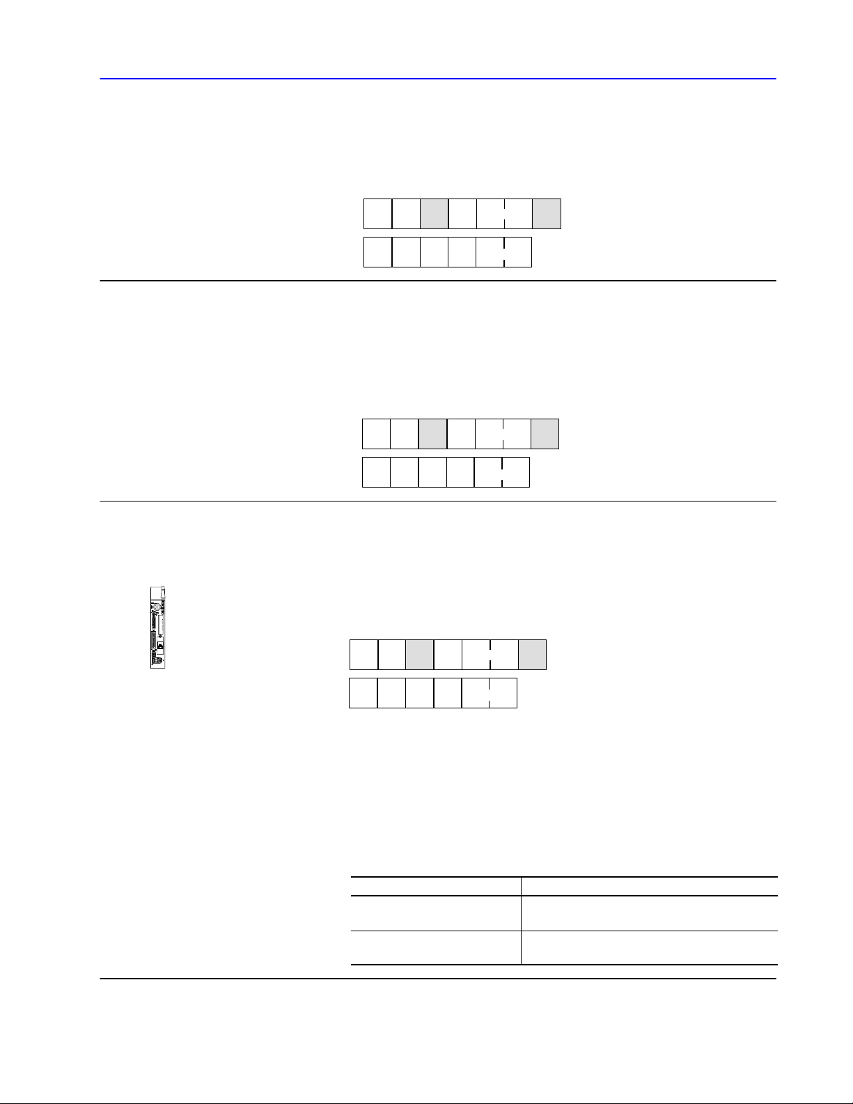
enable outputs
7–9Communication Commands
• 1774PLC
• 1774PLC
Returns control of the outputs to the 1774-PLC ladder diagram
program. Use this command to cancel the effect of disable outputs.
C
R
DST SRC
SRC DST
CMD
07
CMD
47
STS
STS
TNS
TNS
FNC
01
enable PLC scanning
Restarts the 1774-PLC processor’s program scanner after a physical
write has been performed.
C
R
DST SRC
SRC DST
CMD
07
CMD
47
STS
STS
TNS
TNS
FNC
03
• PLC2
enter download mode
Puts the PLC-2 processor in the download mode. Use this command
on a PLC-2 node before sending a physical write to the node.
C
R
DST SRC
SRC DST
CMD
07
CMD
47
STS
STS
TNS
TNS
Important: For early revisions of the 1771-KA2 and the industrial
terminal, when you send an enter download/upload
mode, the industrial terminal port is disabled until you
send an exit download/upload mode. When the
industrial terminal port is disabled, the industrial
terminal enters the mode select state. To leave this
state, you must manually select a mode at the industrial
terminal.
If you are using Use
•1771KA/A revision F
•1771KG/A
•1771KA2/B
•1771KG/B or later
FNC
04
enter download mode before sending physical read
commands.
enter upload mode before sending physical read
commands.
Publication
17706.5.16 - October 1996
Page 97

7–10 Communication Commands
enter upload mode
Puts the PLC-2 processor in Upload mode. Use this command on a
PLC-2 node before sending a physical read to the node.
• PLC2
• PLC2
C
R
DST SRC
SRC DST
CMD
07
CMD
47
STS
STS
TNS
TNS
FNC
06
Important: When you send an enter upload mode, the industrial
terminal port is disabled until you send an exit
download/upload mode.
exit download/upload mode
Takes the PLC-2 processor out of the Upload or Download mode.
Use this command to restart the PLC-2 processor after performing an
upload or download operation.
Important: Do not send this command after a download/upload
command; you must recycle power to the 1771-KA,
-KA2, -KG, or 1785-KA3 module to enable industrial
terminal communication.
C
DST SRC
CMD
07
STS
TNS
FNC
05
• PLC3
• PLC5/250
R
SRC DST
CMD
47
STS
TNS
You must remove the temporary End statement from the beginning
of the program and re-insert the first byte of the program.
file read (read file)
Reads data, starting at a file symbol or a block address. This starting
address must point to a file of words.
FNC
CMD
C
R
The DATA field may be replaced by an EXT STS field if there is an error
0F
CMD
4F
STS
STS
TNSDST SRC
TNSSRC DST
Packet
Offset
04
Data max. 244 bytes
or 122 words)
Total
Trans
Logical
(2 51 bytes.)
.
Address
Size
Publication
17706.5.16 - October 1996
Page 98
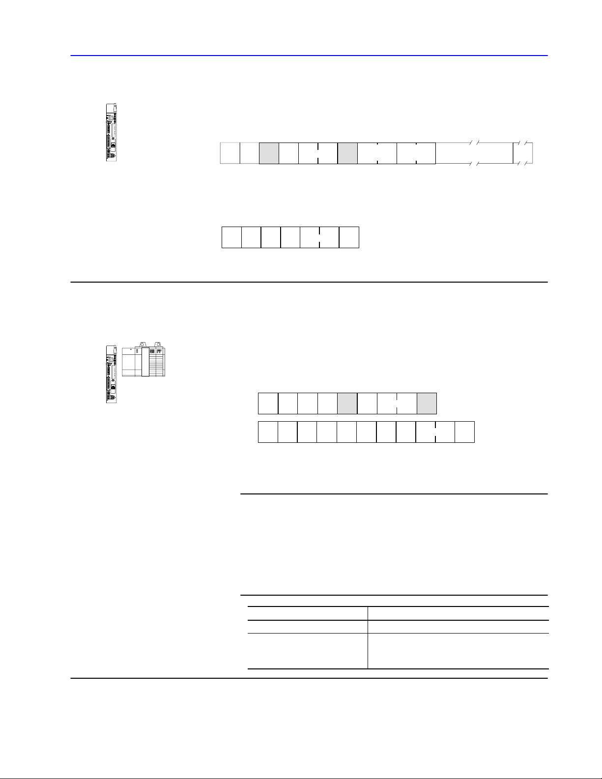
7–11Communication Commands
file write (write file)
Writes data, starting at a file symbol or block address. This starting
address must point to a file of words.
• PLC3
• PLC5/250
• PLC5
• PLC5/250
(receive
only)
• PLC5/VME
•
SLC 500
•
SLC 5/03
•
SLC 5/04
Packet
C
CMD
STS
0F
(up to [239 bytes - the PLC3 logical address length]; must be an even number)
FNC
TNSDST SRC
Offset
03
This reply is the same as the reply packet for all unprotected,
protected, and privileged bit writes.
R
CMD
STS
4F
The
EXT STS field may be attached to the reply packet if an error occurs.
TNSSRC DST
EXT
STS
get edit resource
Secures the edit resource (sole access) for the programming device.
Once a programming device has obtained the edit resource, another
node cannot write to or modify the device.
DST SRC
C
R
PSN PSN
LNH
LNH
HI
DST
LO
The
EXT STS field may be attached to the reply packet only when there is an error
LNH - length of the optional portion of the reply packet in bytes.
CMD
0F
PSN SRC PSN
STS
CMD
4F
TNS
STS
Total
Trans
FNC
11
TNS
Logical
Address
(2 51 bytes.)
EXT
STS
Data
.
"
First four words of get edit resource
The first four words are currently unused and unexamined.
To assure compatibility with any future use of these bytes, they
should be initialized to 0. DST, PSN, and SRC are included for
reference only.
For this processor This access is cleared by
SLC 500, SLC 5/01, SLC 5/02 any node sending a return edit resource
the programming device or via a timed mechanism
SLC 5/03, SLC 5/04
internal to the processor sending a return edit
resource
Publication
17706.5.16 - October 1996
Page 99

7–12 Communication Commands
initialize memory
Resets the processor’s memory to the default directory (the directory
the processor is shipped with). Using this command does not reset
the communication configuration.
•
MicroLogix 1000
• PLC5
• PLC5/250
(receive only)
•
SLC 500
•
SLC 5/03
•
SLC 5/04
• PLC5
C
R
DST SRC
SRC DST
CMD
0F
CMD
4F
EXT STS field may be attached to the reply packet if an error occurs.
The
STS
STS
TNS
TNS
FNC
57
EXT
STS
modify PLC2 compatibility file
Changes the compatibility mode file so that communication from a
PLC-2 processor (or a node emulating a PLC-2 processor) at the
given node address uses the file specified. This change in the default
file for PLC-2 compatibility mode remains in effect until this
command is issued again to change it or until memory is cleared.
Cycling the power to the PLC-5 processor does not reset the default.
The link ID and node address are one byte each. The file number is
two bytes.
C
DST SRC
CMD
0F
STS
TNS
FNC
5E
Link
ID
Node
Addr
File
number
Publication
17706.5.16 - October 1996
R
SRC DST
CMD
STS
4F
EXT STS field may be attached to the reply packet if there is an error
The
TNS
EXT
STS
.
Page 100

open file
Opens a file in an SLC 500 processor. If the file is successfully
opened, a Tag (low byte, high byte) is returned.
7–13Communication Commands
•
SLC 500
•
SLC 5/03
•
SLC 5/04
• 1774PLC
• PLC2
• PLC3
Protection
C
R
CMD
STS
STS
TNSDST SRC
TNS
01h = read
02h = not supported
03h = read/write
0F
SRC DST
CMD
4F
Protection -
Tag is used to access the open file using a
file write. Tag is also used to close the file. The T
EXT STS field if there is an error
FNC
81
Ta g
.
File
number
protected type file read
File
type
ag field may be replaced by an
or
protected type
physical read
Uploads data from the PLC data table or program memory.
1774-PLC and PLC-2
C
R
DST SRC
SRC DST
CMD
STS
04
CMD
44
Use the SIZE field to specify the number of bytes to be read. T
PLC words, SIZE should be an even value because PLC words are two bytes.
TNS ADDR SIZE
STS
TNS
Data
(max. 244 bytes)
o specify a number of
PLC-3
For PLC-3 processors, the destination interface module accepts this
command only after the source node has successfully transmitted a
shutdown request.
DST SRC
C
R
CMD
0F
SRC DST
CMD
4F
This command must request an even number of bytes.
The
EXT STS field may replace the DATA field if there is an error
STS
STS
TNS
TNS
TNS
FNC
PLC3
09
Data
(max. 244 bytes
or 122 words)
phys. address
Size
.
Publication
17706.5.16 - October 1996
 Loading...