

Page 1

CS3000 MMI SW-Version 6.1
Control and Configuration Software
for FlexPak3000 V2.0 - 4.3,
GV3000 V2.0 - 6.0 and Liqui-Flo
Instruction Manual
Manual P/N: 899.05.84
Firmware P/N: 788.05.30
User Manual: 49‘1307e (04)
Publication: CS3000-UM003D-EN
Page 2
The information in this manual is subject to change without notice.
Throughout this manual, the following notes are used to alert you to safety considerations:
ATTENTION:Identifies information about practices or circumstances that can lead to personal
injury or death, property damage, or economic loss.
!
Important: Identifies information that is critical for successful application and understanding of the product.
The thick black bar shown on the outside margin of this page will be used throughout this instruction manual to
signify new or revised text or figures.
ATTENTION:Only qualified electrical personnel familiar with the construction and operation of
this equipment and the hazards involved should install, operate, or service this equipment. Read
!
and understand this manual and other applicable manuals in their entirety before proceeding.
Failure to observe this precaution could result in severe bodily injury or loss of life.
ATTENTION:Only qualified personnel should develop or change drive configuration. Read and
understand the drive instruction manual in its entirety before proceeding with configuration edit.
Failure to observe this precaution could result in severe bodily injury or loss of life.
ATTENTION:Parameter assignments made while the software in controlling and communicating
to the drive overwrite the parameter values in the drive. Read and understand this manual and
all other applicable manuals in their entirety before changing drive parameter values. Failure to
observe this precaution could result in severe bodily injury or loss of life.
IBM is a trademark of International Business Machine Corporation.
Microsoft, Windows, and MS-DOS are trademarks of Microsoft Corporation.
Pentium is a trademark of Intel Corporation.
GV3000, Liqui-Flo, FlexPak, and Reliance are trademarks of Rockwell Automation.
©1999 Rockwell International Corporation
Page 3

Chapter 1 Introduction
1.1 About the Control and Configuration Software................................................ 1-1
1.2 Software Requirements................ ...... ....... ...... ....... ...... ....... ...... ...................... 1-1
1.3 Hardware Requirements.................................................................................. 1-2
1.4 Cables ............................................................................................................. 1-2
1.5 Safety Information ........................................................................................... 1-3
1.6 Purpose of This Manual................................................................................... 1-3
1.7 Intended Audience........................................................................................... 1-3
1.8 Terms Used in This Manual............................................................................. 1-4
1.9 Where to Find Additional Information .............................................................. 1-4
Chapter 2 Getting Started
2.1 Before Installing the Software..........................................................................2-1
2.2 Installing the CS3000 Software on a Personal Computer ............................... 2-2
2.3 Setting Up Communication Between the CS3000 Software and the Drive .....2-3
2.3.1 Connecting the Personal Computer’s Serial Port to the Drive .............. 2-3
2.3.2 Setting Up the Drive to Communicate with the Personal Computer...... 2-5
2.3.3 Selecting the Correct Communication Port........................................... 2-5
2.4 Starting the Software .......................................................................................2-5
2.5 About the Menus and Toolbars .... ...... ....... ...... ....... ....................................... .. 2-7
2.5.1 About the Menus............................................................. ....... ...... ....... .. 2-7
2.5.2 About the Toolbar .. ....... ...... ...... ....... ...... ....... ...... ....... ............................ 2-8
2.6 Exiting the CS3000 Software......................................................................... 2-10
CONTENTS
Chapter 3 Configuring the Drive
3.1 Selecting a Drive ............. ....................................... ...... ....... ...... ....... ...... ....... .. 3-1
3.2 Creating a New Configuration .........................................................................3-2
3.3 Opening a Drive Configuration File ................................................................. 3-3
3.4 Opening a Configuration File for a Different Version of the Same Drive .........3-5
3.5 Editing a Configuration .............................. ...... ....... ...... ....... ...... ....... ...... ....... .. 3-7
3.5.1 Assigning Parameter Values.................................................................3-7
3.5.2 Ending an Editing Session ....................................................................3-9
3.5.3 Entering and Editing a Configuration Description.................................. 3-9
3.6 Saving a Drive Configuration............................................... ...... ....... ...... ....... 3-10
3.7 Saving the Open Drive Configuration to Another File.................................... 3-11
3.8 Printing a Configuration................................................................................. 3-12
Chapter 4 Uploading and Downloading Drive Configurations
4.1 Uploading a Drive Configuration...................................................................... 4-1
4.2 Downloading a Configuration to the Drive.......................................................4-2
4.3 Comparing the Drive Configuration to the Opened Configuration ................... 4-3
4.4 Comparing the Parameter Values in the Opened Configuration with
Those in Another Configuration File ................................................................ 4-4
Contents
I
Page 4

Chapter 5 Tuning GV3000 and Liqui-Flo Vector Drives
5.1 Saving the Drive Configuration Before Tuning.................................................5-2
5.2 Using Standard Tuning ....................................................................................5-2
5.3 Using Custom Tuning.......................................................................................5-5
5.3.1 Setting Motor Data ................................................................................5-5
5.3.2 Tuning the Torque/Flux Loop ................................................................5-6
5.3.3 Tuning the Speed Loop .........................................................................5-7
5.3.4 Using Profile To Check Drive Tuning.....................................................5-9
Chapter 6 Monitoring and Editing Drive Parameters
6.1 About the Parameter Monitor........................... ...... ....... ...... ....... ...... ....... ...... ...6-1
6.2 Adding Parameters to the Monitor List.............................................................6-3
6.3 Removing Parameters from the Monitor List....................................................6-3
6.4 Assigning Values to Parameters on the Drive..................................................6-4
6.5 Saving a Monitor List........................................................................................6-6
6.6 Displaying a Monitor List..................................................................................6-7
6.7 Clearing the Monitor List Display .....................................................................6-8
6.8 Exiting the CS3000 Parameter Monitor............................................................6-8
Chapter 7 Monitoring Drive Status and Alarms
7.1 Displaying and Clearing the Fault Log and Alarm Log.....................................7-1
7.2 Monitoring Drive Status....................................................................................7-4
7.3 Restoring Default Values to Drive Parameters ................................................7-5
7.4 Saving Drive Parameter Values to Non-Volatile Memory on the Drive............7-5
7.5 Restoring Drive Parameter Values from Non-Volatile Memory in the Drive.....7-6
Chapter 8 Controlling the Drive
8.1 Connecting a Drive...........................................................................................8-1
8.2 Disconnecting a Drive ......................................................................................8-1
8.3 Controlling a Drive............................................................................................8-2
8.4 Selecting the Control Source ...........................................................................8-4
8.5 Selecting the Reference Mode (Auto/Manual) .................................................8-4
8.6 Selecting the Direction of Motor Rotation.........................................................8-4
8.7 Setting the Drive Reference.............................................................................8-4
8.8 Setting the Jog Reference................................................................................8-5
8.9 Starting and Stopping the Drive.......................................................................8-5
8.10 Monitoring Drive Indicators ..............................................................................8-6
Chapter 9 Using PC Scope
9.1 About PC Scope..................... ....... ...... ...... ....... ...... ....... ...................................9-1
9.2 Setting Up a Trace ...........................................................................................9-4
9.2.1 Specifying Signals .................................................................................9-5
9.2.2 Setting Up Data Sampling .....................................................................9-5
9.2.3 Setting Up the Trigger............................................................................9-6
9.3 Acquiring a Trace.............................................................................................9-7
9.4 Working with the Cursors................................. ...... ....... ...... ....... ...... ....... ...... ...9-8
9.4.1 Moving a Cursor ....................................................................................9-9
9.4.2 Specifying the Cursors To Track Each Other ........................................9-9
9.5 Changing Views ...............................................................................................9-9
9.5.1 Turning Cursors On and Off ..................................................................9-9
9.5.2 Magnifying the Trace Display ..............................................................9-10
9.6 Taking a Trace Snapshot...............................................................................9-10
9.6.1 Taking a Snapshot...............................................................................9-10
II
Control and Configuration Software V6.1
Page 5

9.6.2 Choosing the Trace Snapshot Colors .................................................9-11
9.7 Saving a Trace File........................................................................................ 9-11
9.8 Clearing the Trace Display and Setup...........................................................9-12
9.9 Opening a Trace File.....................................................................................9-12
9.10 Closing PC Scope .........................................................................................9-13
Chapter 10 Troubleshooting
10.1 Using Error Messages................................................................................... 10-1
10.2 Getting Assistance from Reliance Electric.....................................................10-1
Appendix A Error Messages ........................................................................................................A-1
Appendix B New Features in Version 6.1 ....................................................................................B-1
Index ..................................... ....... ...... ....... ...... ...... ....................................... ....... ...... .. Index-1
Contents
III
Page 6

IV
Control and Configuration Software V6.1
Page 7

List of Figures
Figure 2.1 – RS-232 Cable Connector Pinouts for Drives with a 9-Pin Connector...2-4
Figure 2.2 – RS-232 Cable Connector Pinouts for Drives with a Terminal
Block Connector................................................................................... 2-4
Figure 2.3 – RS-232 Cable Connector Pinouts for Drives with a 25-Pin
Connector.............................................................................................2-5
Figure 2.4 – Sample Main Window for an Established Connection..........................2-6
Figure 2.5 – Graphical Tool Bar................................................................................2-8
Figure 3.1 – Drive Select—Disconnected................................................................. 3-1
Figure 3.2 – File New Window..................................................................................3-2
Figure 3.3 – Open Configuration File Dialog Box .....................................................3-3
Figure 3.4 – Configuration Editor..............................................................................3-7
Figure 3.5 – Configuration Description Dialog Box...................................................3-9
Figure 3.6 – Configuration Description Pop-Up Edit Menu.....................................3-10
Figure 3.7 – Save Configuration Dialog Box...........................................................3-11
Figure 3.8 – Sample Configuration File Printout.....................................................3-12
Figure 4.1 – Compare Configuration File Dialog Box ...............................................4-4
Figure 4.2 – Configuration Differences Dialog Box...................................................4-5
Figure 5.1 – Drive Tuning Menu............................................................................... 5-1
Figure 5.2 – Example of Motor Data Dialog Box ......................................................5-2
Figure 5.3 – Example of Setting Motor Data Values................................................. 5-4
Figure 5.4 – Example of Setting Torque/Flux Loop Data Values.............................. 5-5
Figure 5.5 – Example of Setting Speed Loop Data Values ......................................5-6
Figure 5.6 – Drive Profile Example........................................................................... 5-7
Figure 6.1 – Parameter Monitor Window.................................................................. 6-2
Figure 6.2 – Add Parameters to Monitor List Dialog Box.......................................... 6-3
Figure 6.3 – Save Monitor List Dialog Box ...............................................................6-6
Figure 6.4 – Recall Monitor List Dialog Box.............................................................. 6-7
Figure 6.5 – Remove Parameters from Monitor List Dialog Box ..............................6-8
Figure 7.1 – Sample Fault Log List Box....................................................................7-1
Figure 7.2 – Sample Alarm Log List Box .................................................................. 7-2
Figure 7.3 – Drive Status Window............................................................................ 7-4
Figure 8.1 – Drive Control Window...........................................................................8-3
Figure 9.1 – The PC Scope Screen..........................................................................9-2
Figure 9.2 – Trace Signal Setup Dialog Box.............................................................9-4
Figure 9.3 – Sample Trace .......................................................................................9-8
Figure 9.4 – Save a Signal Trace File Dialog Box.................................................. 9-11
Figure 9.5 – Open Signal Trace File Dialog Box .................................................... 9-12
Contents
V
Page 8

VI
Control and Configuration Software V6.1
Page 9

List of Tables
Table 1.1 – Cables.................................................................................................... 1-2
Table 1.2 – Terms.....................................................................................................1-4
Table 2.1 – Overview of the Menu............................................................................2-7
Table 2.2 – Toolbar Icons and Menus...................................................................... 2-9
Table 3.1 – Editing Configuration Descriptions.......................................................3-10
Table 4.1 – Compare Dialog Box Functions............................................................. 4-3
Table 4.2 – Configuration Differences Dialog Box Options ......................................4-5
Table 7.1 – Using the Fault and Alarm Logs ............................................................7-3
Table 7.2 – Drive Status Indicators...........................................................................7-5
Table 9.1 – PC Scope Toolbar Buttons.................................................................... 9-3
Contents
VII
Page 10

VIII
Control and Configuration Software V6.1
Page 11

CHAPTER 1
Introduction
This section describes the computer requirements for the CS3000 software and
presents general information about the software and this manual.
1.1 About the Control and Configuration Software
Use the Control and Configuration (CS3000) software to help you develop drive
configurations on your personal computer for GV3000, Liqui-Flo, and
FlexPak 3000 drives. The CS3000 software communicates with the drive through the
personal computer’s RS-232 port.
By using the CS3000 software, you can:
• Create, store, upload, download, and print drive configurations.
• Monitor drive status.
• Monitor and change drive parameters using a personal computer.
• Control the drive (start, stop, etc.).
• Compare a configuration in the drive with one in the personal computer.
• Read and reset the drive fault and error log.
• Create, modify , and store drive configurations.
• Send Memory Save, Memory Restore, and Restore Defaults commands to a
drive.
• Display trace signals in the drive.
1.2 Software Requirements
The CS3000 software requires Microsoft Windows 3.1 or later versions (including
Windows 98 or Windows NT). Make sure Windows is installed and configured on your
personal computer before attempting to install the CS3000 software.
Introduction
1-1
Page 12

1.3 Hardware Requirements
Before installing and using the CS3000 software make sure you have the following
hardware:
•
An IBM or IBM-compatible 486 or Pentium personal computer running Windows
3.1, Windows 98, or Windows NT.
•
16 Mbytes of RAM (minimum)
•
A hard drive with at least 1 Mbytes free space available for the CS3000 software
•
A 3.5" floppy drive
•
A Monochrome or color monitor: VGA or better
•
An RS-232 serial COM port for communicating with the drive
•
An RS-232 serial cable with:
•
A 25-pin or 9-pin D-shell connector for your personal computer
•
A 9-pin or 25-pin male D-shell connector for the drive.
The GV3000 drive is equipped with a terminal strip as well as a 9-pin D-shell
connector. Either one can be used to connect to the personal computer. Refer to
section 2.3.1 for additional information.
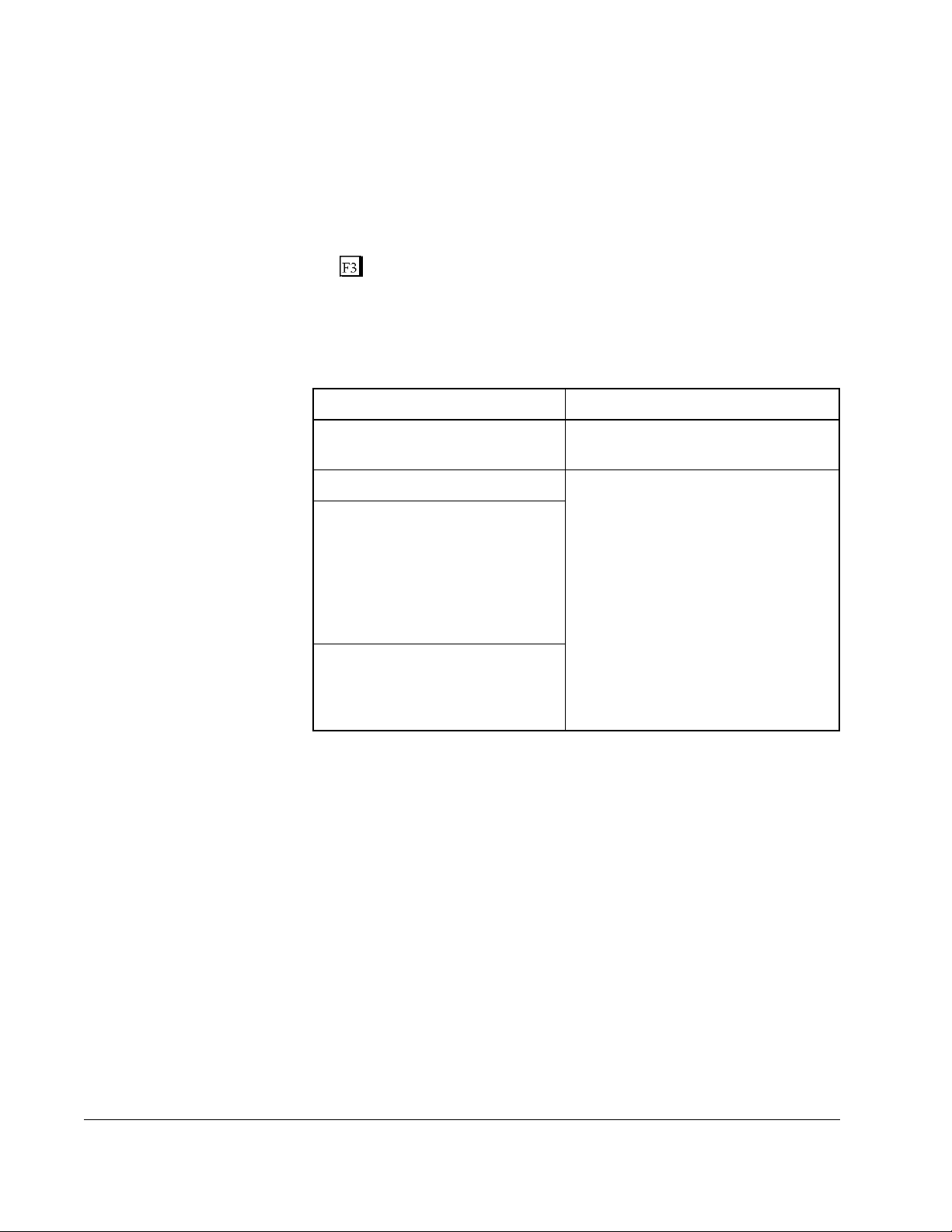
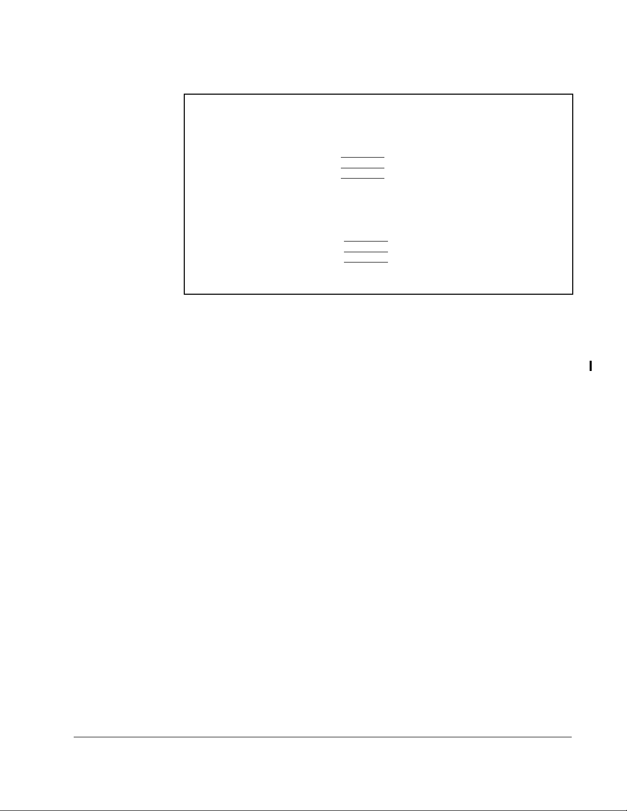
1.4 Cables
The Interface cable can be used to connect the personal computer to the drive.
The Adapter is required, if your personal computer has a 25-pin COM port and you
want to use one of the specified Interface cables.
Drive Drive
ConnectorPCConnector
FlexPak3000
GV3000
Liqui-Flo 25-pin
25-pin 9-pin
25-pin
9-pin 9-pin
Table 1.1 - Cables
Interface Cable Adapter Cable
25-pin to 9-pin
9-pin to 9-pin
25-pin to 9-pin
25-pin to 9-pin
Part No.
772.27.00
772.27.20
772.27.10
772.27.20
1-2
Control and Configuration Software V6.1
Page 13
1.5 Safety Information
ATTENTION:Do not run other Windows or DOS software applications
while you are using the CS3000 software for drive control. Unexpected
!
The CS3000 software operates as a Windows 3.1 application. It cannot preempt other
applications or functions in Windows and, therefore, cannot guarantee a response
time to user input actions. Using other applications while controlling a drive with the
CS3000 software can tie up PC resources and cause drive commands to be delayed.
To prevent drive commands (run, stop, and jog) from unexpectedly executing, the
CS3000 software specifies a time-out period (approximately 2 seconds) when it
establishes a link with the drive. While the link is established, the CS3000 software
sends messages to the drive to validate the link. If a message fails to reach the drive
within the time-out period because program execution has been delayed, the drive
invalidates the link. If the link becomes invalid, the drive does not accept drive
commands. If the drive was running, it stops, and a serial fault is generated.
Before a drive control command is sent to the drive, the drive’s status is checked to
validate the link. If communication between the CS3000 software and the drive have
been interrupted and you have selected a drive command, the command is not sent
and a message is displayed.
The time-out period is also used by the Parameter Monitor and Download functions,
both of which could be running while the Drive Control Window is open. If the link
becomes invalid while these functions are running, a message will be displayed in the
Drive Control window before the link is re-established. When you select the Download
command while the Drive Control window is open, you cannot execute drive command
controls until the download is complete.
machine motion could result. Failure to observe this precaution could
result in severe bodily injury or loss of life.
1.6 Purpose of This Manual
This manual describes how to use the Control and Configuration software (CS3000) to
configure GV3000, Liqui-Flo, and FlexPak 3000 drives. Refer to the appropriate drive
instruction manual for information about parameters and RS-232 connection options.
1.7 Intended Audience
This manual is written for those who must install the CS3000 software and use the
software to configure and run GV3000, Liqui-Flo, and FlexPak drives. This manual
assumes you are familiar with Windows and makes references to it throughout.
You will need to know the basic Windows functions before using the CS3000 software.
Introduction
1-3
Page 14

1.8 Terms Used in This Manual
The following terms are used throughout this manual:
Table 1.2 – Terms
CS3000 Control and Configuration
COM port communication port
configuration file drive configurations stored on the personal computer that can only be read and
written to by the CS3000 software
disk drive the personal computer’s 3.5 inch disk drive
drive the Power Module and regulator combination that controls a motor
Drives can be configured using the CS3000 software.
drive configuration the set of drive parameters and assignment values that specify how the drive
runs
hard drive the personal computer’s hard disk drive
opened configuration the configuration that is active in the CS3000 software
1.9 Where to Find Additional Information
See the following instruction manuals for more information about the drives that can
be configured using the CS3000 software:
• GV3000 AC Drive Instruction Manuals
• Liqui-Flo AC Drive Instruction Manuals
• FlexPak 3000 DC Drive Instruction Manuals
1-4
Control and Configuration Software V6.1
Page 15

This section describes how to install the CS3000 software and use the menus and
toolbars.
2.1 Before Installing the Software
If you have an older version of the CS3000 software on your PC, you should either:
• delete the old version before installing the new version
Keep any working files such as, the drive configuration and monitor list files, for
use with the new version of the CS3000 software
• install the new version of CS3000 software in a new directory
You can select the new directory name during installation. If you choose this
option, change the name of the program folder for the old version of the CS3000
software to a name other than CS3000, such as “CS3000, V 5.0.” Otherwise, the
new version will replace the old version in that program group, although it will not
overwrite any of the files on the hard drive. See your Windows documentation for
more information about changing the name of a program group.
CHAPTER 2
Getting Started
Before installing the new CS3000 software, back up the files to another floppy disk.
See your Windows documentation for instructions about using the File Manager or
Explorer to copy disks.
Getting Started
2-1
Page 16
2.2 Installing the CS3000 Software on a Personal Computer
All files needed to install the CS3000 software are on the 3.5" CS3000 disk. Use the
following steps to install the CS3000 software.
Important: To exit installation, select the Exit icon in the lower right corner or press
Step 1. Start Microsoft Windows.
Step 2. Insert the CS3000 software disk into the 3.5" floppy drive.
Step 3. Follow the steps for operating the system you are using:
Windows 3.1 Windows 98 or NT
a. From the Program Manager
menu bar, select File.
b. Select Run. b. In the Open field, type in the
c. In the Command Line field,
type in the drive letter
followed by \SETUP.EXE. For
example, if your 3.5" floppy
drive is A:, you would type
A:\SETUP.EXE.
d. Select OK. The message
“Setup is initializing. Please
wait . . .” is displayed for
about a minute.
Step 4. At the prompt “Enter location for Control and Configuration Software program
files,” specify the location where you want to install the software. The location
defaults to C:\CS3000. Select OK when the drive and directory are correct.
The installation software automatically creates the new directory on the hard
drive you enter.
Step 5. At the prompt “Enter desired default location for Control and Configuration
Software work files,” specify the location where you want to store the drive
configuration files. The default location is C:\CS3000\WORK. Select OK
when the drive and directory are correct.
a. From the Start Menu, select Run.
drive letter followed by SETUP.
For example, if your 3.5" floppy
drive is A:, you would type
A:SETUP
The message “Setup is
initializing. Please wait . . .” is
displayed for about a minute.
2-2
The program begins its installation sequence. You see the following
messages during installation:
• “Decompressing Control and Configuration Software files . . .” for about a
minute, then
• “Creating Program Group and Icon” for a few seconds
Control and Configuration Software V6.1
Page 17

After creating the program group and icon, the CS3000 software installation is
complete. The installation program automatically exits, and you return to
Windows. You should see a new program group titled “Control and
Configuration.”
Step 6. Remove the CS3000 disk from the 3.5" drive.
The CS3000 software is now installed and ready to use.
If you had an older version of the CS3000 software installed, you can use the
configuration and monitor files you created with that version. To make it easier to use
the existing configuration and monitor files, move them to the working directory of the
new version of software. The working directory is normally C:\CS3000\WORK.
Configuration files typically have file extensions of .CNF; monitor files typically have
.MON file extensions. See the Windows documentation for information about moving
files.
2.3 Setting Up Communication Between the CS3000 Software and the Drive
The following sections describe the setup required for communication between the
CS3000 software and the drive. To enable communicati on between the CS3000
software and the drive:
• Physically connect the personal computer to the drive through a serial port
connection (see section 2.3.1)
• Set up the drive for communication through a serial port (see section 2.3.2)
• Select the correct communication port on the personal computer (see section
2.3.3)
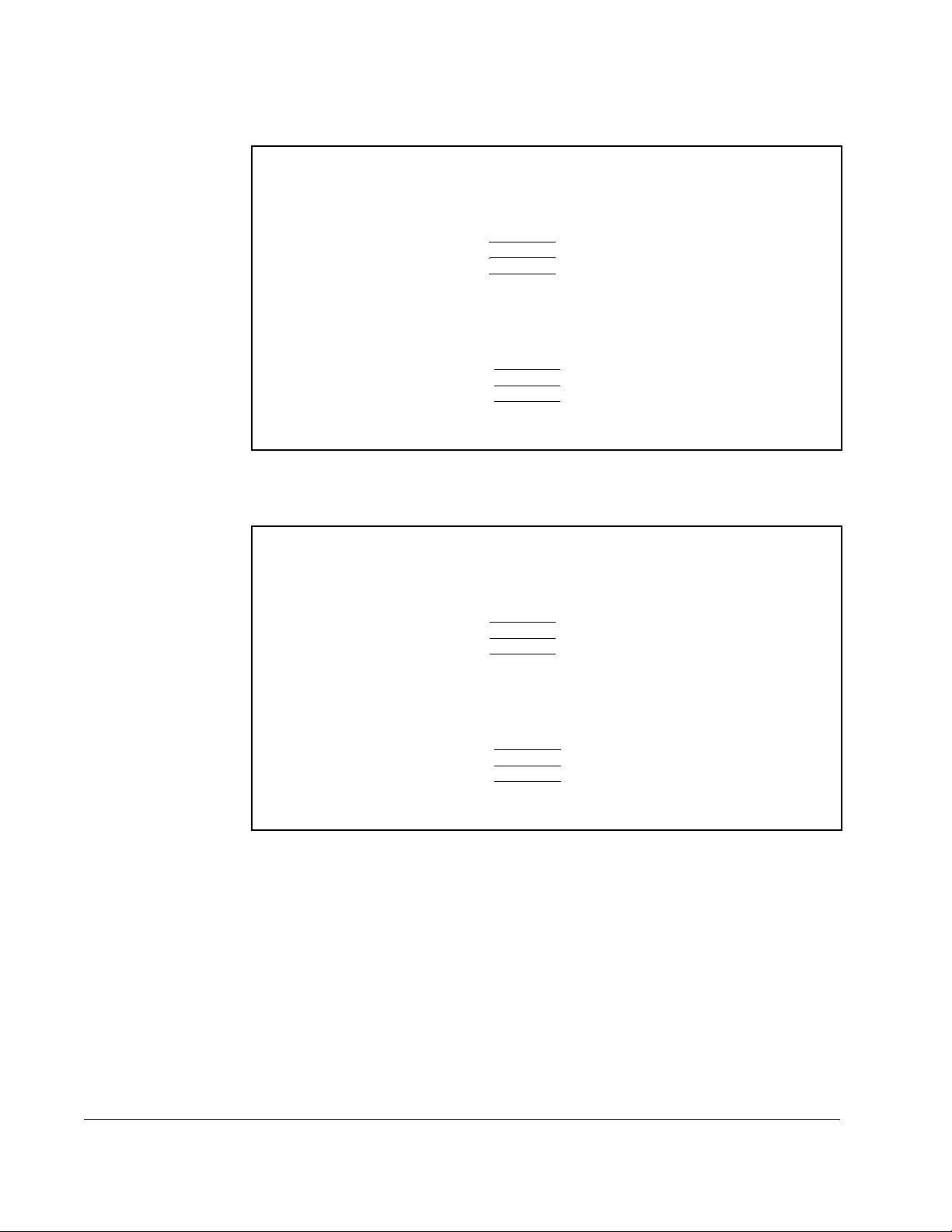
2.3.1 Connecting the Personal Computer’s Serial Port to the Drive
For the CS3000 software to communicate with the drive, connect the personal
computer to the drive using an appropriate cable by following these instructions:
Step 1. The drive’s RS-232 port typically uses a 9-pin or 25-pin female D-shell
connector. Connect the communication cable’s 9-pin or 25-pin male
connector to the drive. Refer to the drive instruction manual for the location of
the RS-232 port on the drive.
Step 2. Connect the other end of the communication cable to the personal
computer’s COM1 port. If the COM1 port is not available, refer to section
2.3.3 for information about selecting the correct communication port. The
personal computer COM port might have either a 25-pin or a 9-pin connector.
Refer to figures 2.1 through 2.3 for cable connector and pinout signals for
9-pin and 25-pin configurations.
Getting Started
2-3
Page 18
.
Personal Computer
25-pin Female
Data OUT
Data IN
Ground
- 3
- 2
- 7
Personal Computer
9-pin Female
Data OUT
Data IN
Ground
Figure 2.1 – RS-232 Cable Connector Pinouts for Drives with a 9-Pin Connector
- 3
- 2
- 5
Personal Computer
25-pin Female
Data OUT
Data IN
Ground
- 3
- 2
- 7
Drive
9-pin Male
3 -
Data IN
2 -
Data OUT
5 -
Ground
Drive
9-pin Male
3 -
Data IN
2 -
Data OUT
5 -
Ground
Drive
Terminal
2 -
Data IN
1 -
Data OUT
3 -
Ground
2-4
Person al Com pute r
9-pin Female
Data OUT
Data IN
Ground
Figure 2.2 – RS-232 Cable Connector Pinouts for Drives with a Terminal Block Connector
- 3
- 2
- 5
Drive
Terminal
2 -
Data IN
1 -
Data OUT
3 -
Ground
Control and Configuration Software V6.1
Page 19
Personal Computer
25-pin Female
Data OUT
Data IN
Ground
- 3
- 2
- 7
Drive
25-pin Male
3 -
Data IN
2 -
Data OUT
7 -
Ground
Person al Com pute r
9-pin Female
Data OUT
Data IN
Ground
Figure 2.3 – RS-232 Cable Connector Pinouts for Drives with a 25-Pin Connector
- 3
- 2
- 5
Drive
25-pin Male
3 -
Data IN
2 -
Data OUT
7 -
Ground
2.3.2 Setting Up the Drive to Communicate with the Personal Computer
For the CS3000 software to communicate with the drive, the drive’s operation control
source parameter must be set up properly. For the GV3000, Liqui-Flo, or
FlexPak 3000 drive, set parameter P.000 to specify serial communication. Refer to the
appropriate drive instruction manual for more information.
2.3.3 Selecting the Correct Communication Port
The CS3000 software communicates with the drive through the personal computer’s
serial port. The software defaults to the COM1 port. If COM1 is already being used,
you must select another COM port. To change the COM port:
Step 1. Start the CS3000 software.
Step 2. From the Options menu, select COM.
Getting Started
Step 3. Select the appropriate COM port from the options displayed in the dialog box.
Step 4. Select OK when the correct COM port is selected. This returns you to the
CS3000 main window.
2.4 Starting the Software
Follow these steps to run the CS3000 software.
Using Windows:
Step 1. Run Windows.
Step 2. When you are in Windows, select the Drive Control and Configuration
program group.
Step 3. Double-click the CS3000 icon within the CS3000 program group.
2-5
Page 20
Using Windows 98:
• From the Start menu, choose Programs and Control and Configuration.
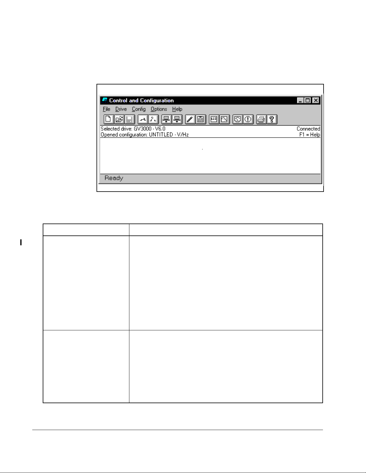
The CS3000 Main Window is displayed as shown in Figure 2.4.
Figure 2.4 – Sample Main Window for an Established Connection
The CS3000 software tries to establish communication with the drive.
If communication is: Then:
established • The drive type (GV3000, Liqui-Flo, or FlexPak 3000) and version is
displayed in the Selected Drive field.
• “UNTITLED” is displayed in the Opened configuration field.
• Drives that have Vector or Volts/Hertz options display the currently
selected option.
• “Connected” is displayed on the right side of the main window.
• The configuration on the drive is uploaded to the personal
computer.
• The drive status window is automatically opened. See section 6.2
for more information.
not established • The Selected Drive field displays either “UNTITLED” or the drive
that was selected the last time the CS3000 software was run. If the
Selected Drive field displays “UNTITLED ,” y ou must select a drive.
See chapter 3 for more information.
• “Disconnected” is displayed on the right side of the main window.
• “UNTITLED” is displayed in the Opened Configuration field.
• Drives that have Vector or Volts/Hertz options display the currently
selected option.
2-6
Control and Configuration Software V6.1
Page 21

If you want to establish communication, but the CS3000 software is not connecting to
the drive:
• Make sure power to the drive is on.
• See section 2.3, Setting Up Communication Between the CS3000 Software
and the Drive.
2.5 About the Menus and Toolbars
Use the menus and toolbar to navigate through the software as described in the
following sections.
2.5.1 About the Menus
Table 2.1 explains the CS3000 software functions you can access through the menu.
Table 2.1 – Overview of the Menu
Use this menu: To:
File Access and manage configuration files
Drive • Connect to and disconnect from the drive
• Select a drive
• Control the drive
• View drive status and alarms
• Use the PC Scope
• Set parameters in the drive to the default values
• Save drive parameter values to the drive’s non-volatile
memory (for drives that support this option)
• Restore values from the drive’s non-volatile memory to its
run-time memory (for drives that support this option)
• Tune GV3000 or Liqui-Flo drives (vector regulation only)
Config • Edit a configuration file
• Enter a description for a configuration file
• Upload or download a configuration file
• Compare a configuration file
Option Choose the COM port on the personal computer which is being
used to connect to the drive.
Help Access the online help.
Getting Started
2-7
Page 22
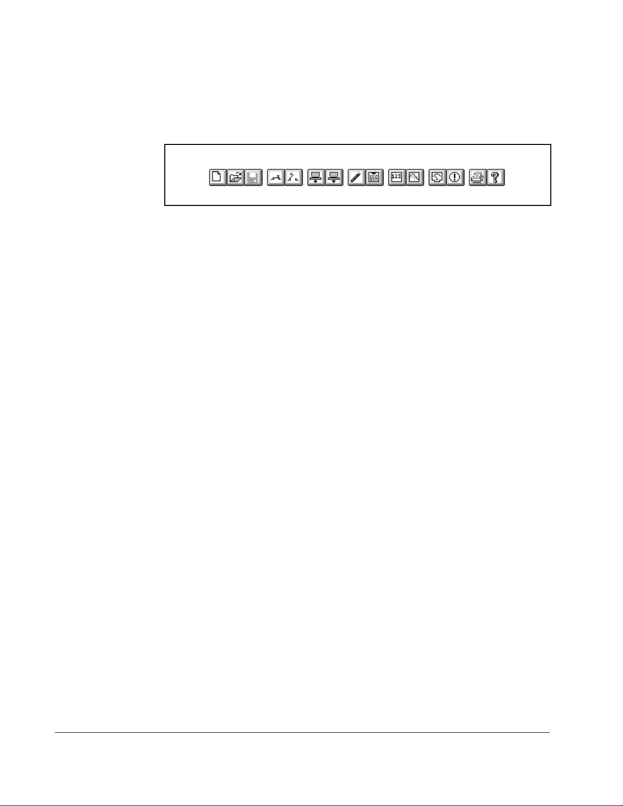
2.5.2 About the Toolbar
A graphical tool bar, displayed below the main menu in the main window, provides a
shortcut method for executing commonly-used main menu functions. Figure 2.5 shows
the toolbar, and table 2.2 lists the functions represented by each icon.
Figure 2.5 – Graphical Tool Bar
2-8
Control and Configuration Software V6.1
Page 23
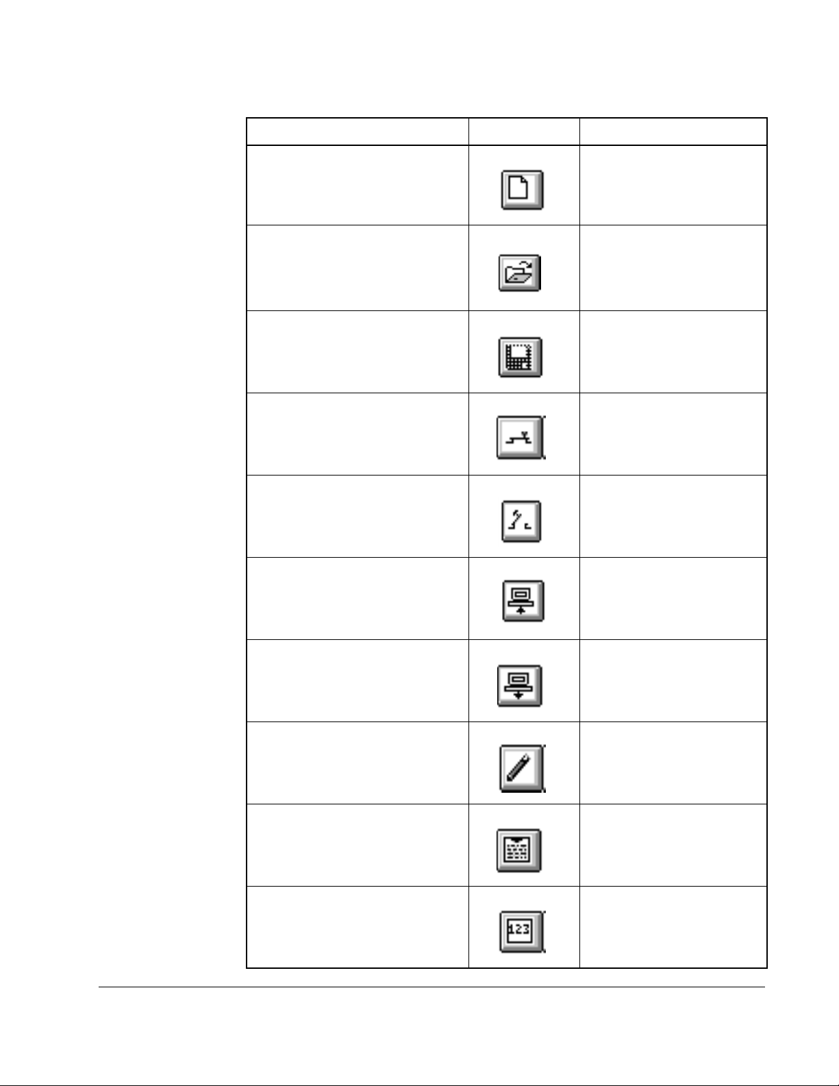
Table 2.2 – Toolbar Icons and Menus
To: Use this icon: Or this menu command:
Create a new configuration file. File | New
Open a configuration file. File | Open
Save a configuration file. File | Save
Connect to a drive. Drive | Connect
Disconnect from a drive. Drive | Disconnect
Upload a configuration file from a
Config | Upload
drive.
Download a configuration file from
Config | Download
a drive.
Edit a configuration file. Config | Edit
Add or edit a description for a
Config | Description
configuration.
Monitor drive parameters. Drive | Parameter Monitor
Getting Started
2-9
Page 24
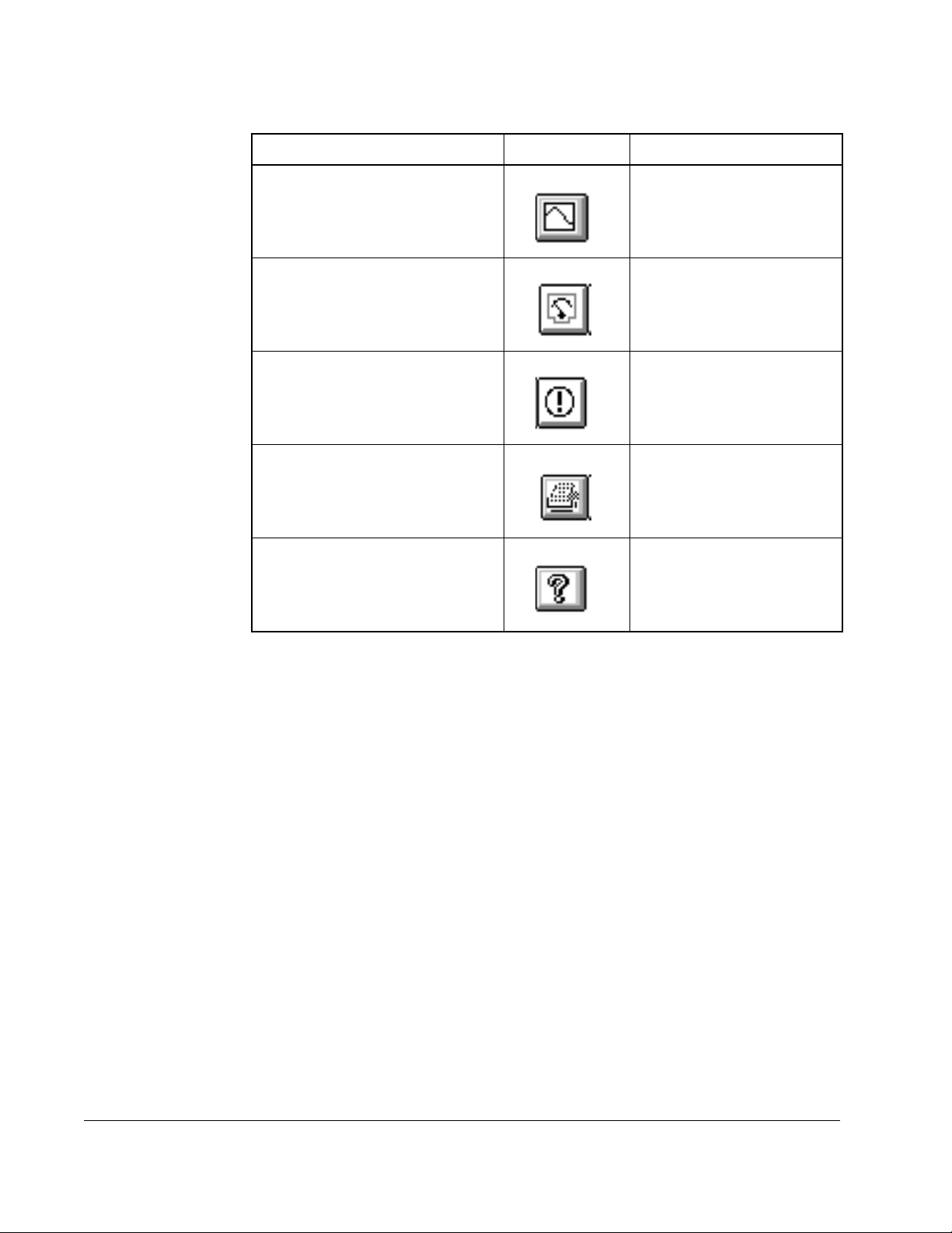
Table 2.2 – Toolbar Icons and Menus
To: Use this icon: Or this menu command:
Access the PC Scope. Drive | PC Scope
Control the drive. Drive | Control
Display the drive’s fault and alarm
logs.
Print a configuration file. File | Print
Access the on-line help Help | Contents
2.6 Exiting the CS3000 Software
To exit the software, choose Exit from the File menu. Exit closes the CS3000 software.
If you modified the open configuration, you are prompted to save the changes to a
configuration file.
Drive | Fault/alarm
2-10
Control and Configuration Software V6.1
Page 25
This chapter describes how to configure a drive.
3.1 Selecting a Drive
To create a configuration for a drive while the drive is not connected to the CS3000
software, you must choose a drive type. Communication with the drive is not
established, but you can open, save and edit configurations. You can also create
Parameter lists using the Parameter Monitor.
For information about establishing communication with a drive, see chapter 8.
To select a drive type, follow these steps:
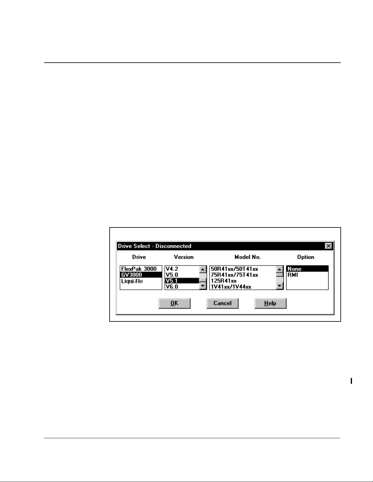
Step 1. From the Drive menu, choose Select.
The Drive Select dialog box is displayed as shown in figure 3.1.
CHAPTER 3
Configuring the Drive
Configuring the Drive
Figure 3.1 – Drive Select—Disconnected
Step 2. Select the drive type and software version as well as the model number and
any options (if supported by the drive). Your choice of a model number
determines the default values for U.xxx and H.xxx parameters.
Step 3. Click OK to select the drive type.
If you select a GV3000 (version 5.0 or later) or Liqui-Flo drive, the options box displays
the option selections. Selecting RMI results in the .r parameters being listed in the
Parameter Monitor and Configuration Editor. You must select the Power Module’s
model number as well.
You can establish communication with the drive by selecting Connect or by re-starting
the CS3000 software. See chapter 8 for more information.
3-1
Page 26
3.2 Creating a New Configuration
You can create a new drive configuration, which sets the parameter values to their
defaults. You assign a name to the configuration file when you save it. See section 3.6
for information about saving configurations.
To create a new configuration:
• From the File menu, choose New, or click .
If a configuration file is already open and has been changed, a dialog box is displayed
that asks if you want to save the current configuration file. If you select Yes, the Save
As dialog box is displayed before the new configuration file is opened.
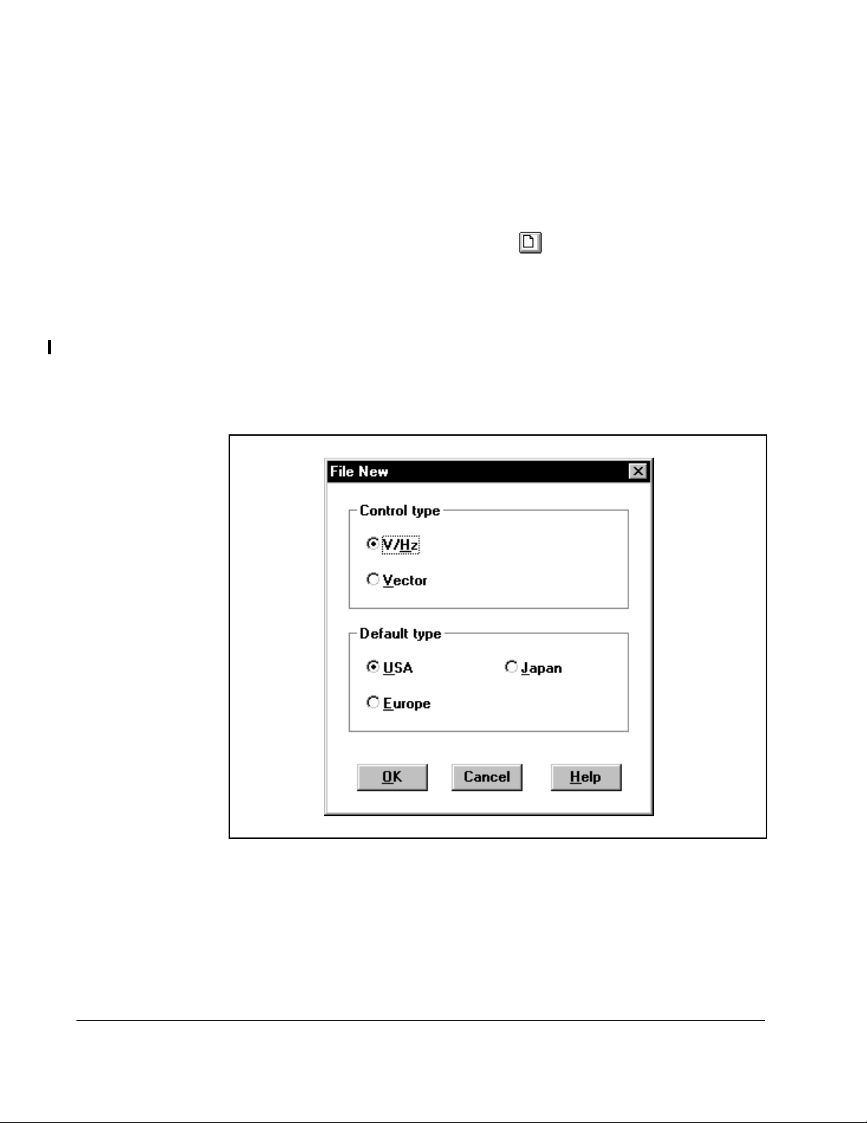
When you create a new GV3000 or Liqui-Flo configuration, the File New dialog box
(figure 3.2) is displayed. This lets you select the Vector or Volts/Hertz control
(regulation) type and USA, Japan, or Europe as the default type.
After making your selections, select OK to open the new configuration file.
3-2
Figure 3.2 – File New Window
When you select the control type, parameters that depend on the control type are
changed to their defaults. The control type determines which parameters are
displayed. See the appropriate drive instruction manual for more information about the
control and default type options.
Control and Configuration Software V6.1
Page 27
3.3 Opening a Drive Configurat ion File
Opening a drive configuration file loads the file from the personal computer to the
CS3000 software. Once the configuration file is opened, you can download it to the
drive.
To open a configuration file:
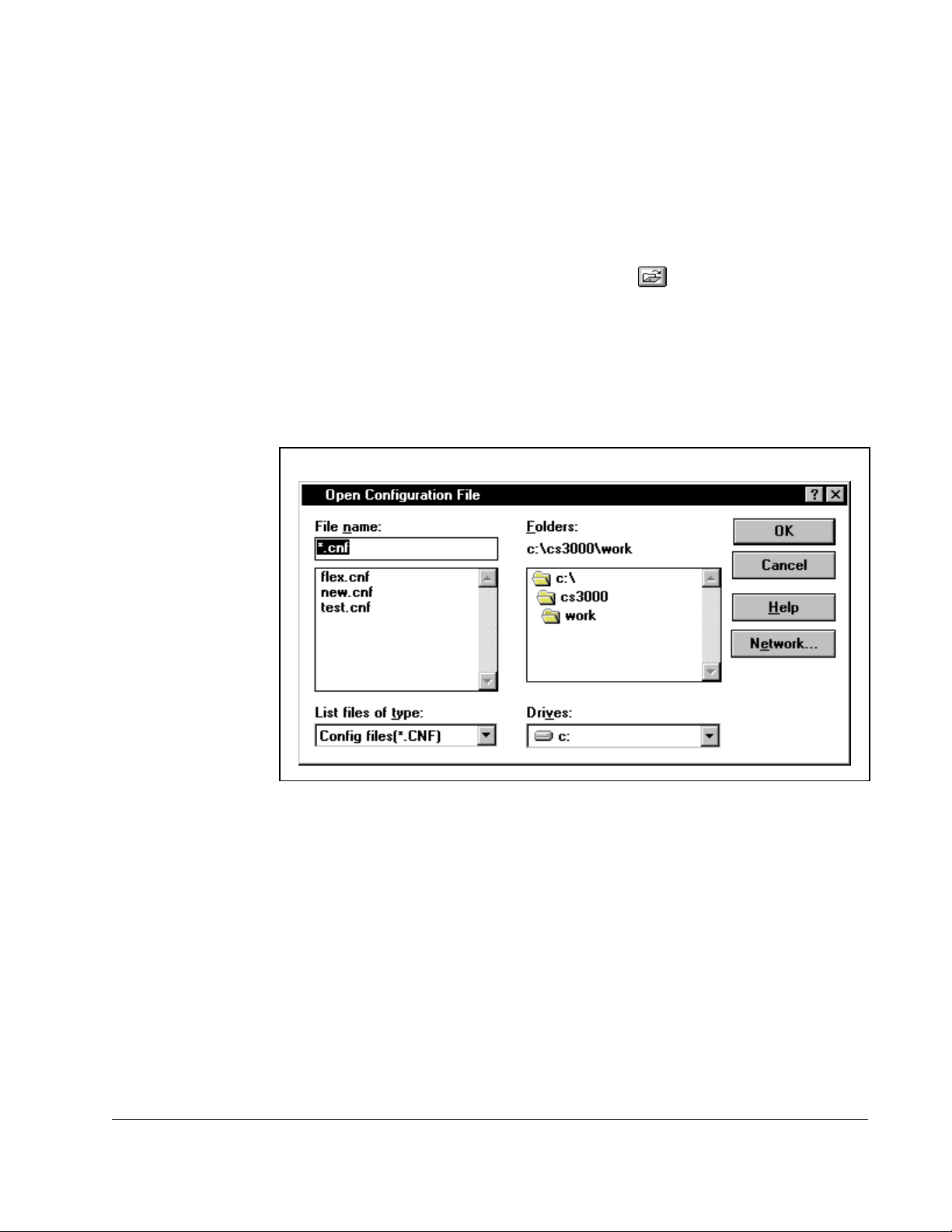
Step 1. From the File menu, choose Open or click .
Step 2. If you already have a configuration file open and have made edits to it that
have not been saved, you are prompted to save the changes. Make the
appropriate selection. See section 3.6 for more information about saving
configuration files.
The Open Configuration File dialog box is displayed. An example is shown in
figure 3. 3.
Configuring the Drive
Figure 3.3 – Open Configuration File Dialog Box
Step 3. The Open Configuration File dialog box defaults to the work directory of the
CS3000 software, which was specified during installation. If this is not the
correct directory, select the directory where the file is stored.
Step 4. Select the name of the file you want to open. The name of the file should be
copied in the File Name box. If not, click on it again.
If the configuration file you want does not have the .CNF extension, it does
not show up automatically in the box under File Name. In this case, select *.*
in the List Files of T ype box to display all of the av ailable files in the File Name
list.
Step 5. Open the file by selecting OK. The name of the file you selected now appears
in the Opened Configuration field of the main window.
To close the dialog box without selecting a file, select Cancel.
3-3
Page 28

If the configuration file was: Then:
not created for the drive currently selected in
the CS3000 software
created for a different version of the currently
selected drive
an error message is displayed and the configuration file is
not opened
Select a configuration file that was created for the selected
drive, or change the selected drive. See section 3.1 for
information about selecting a drive.
a message box is displayed
Refer to section 3.4 for more information about opening a
configuration file for a different version of the same drive.
3-4
Control and Configuration Software V6.1
Page 29
3.4 Opening a Configuration File for a Different Version of the Same Drive
Configuration files include version information about the drive. When you open a
configuration file, the CS3000 software compares the configuration file’s drive version
to the version of the selected drive. If the versions are different, a message box alerts
you of the difference.
.
To: Do the following: Then:
not open the file Choose No. The software returns to the main window without
opening the file.
to copy the configuration file
to the CS3000 software
Choose Yes. A copy of the original configuration file is created.
Then the CS3000 software checks for differences
between the parameters in the copy and the
parameters in the currently selected drive.
If no parameter differences are found, the CS3000
main window is displayed and the opened
configuration is named “UNTITLED.” The original
configuration file is not changed. To save the new
configuration, see section 3.6.
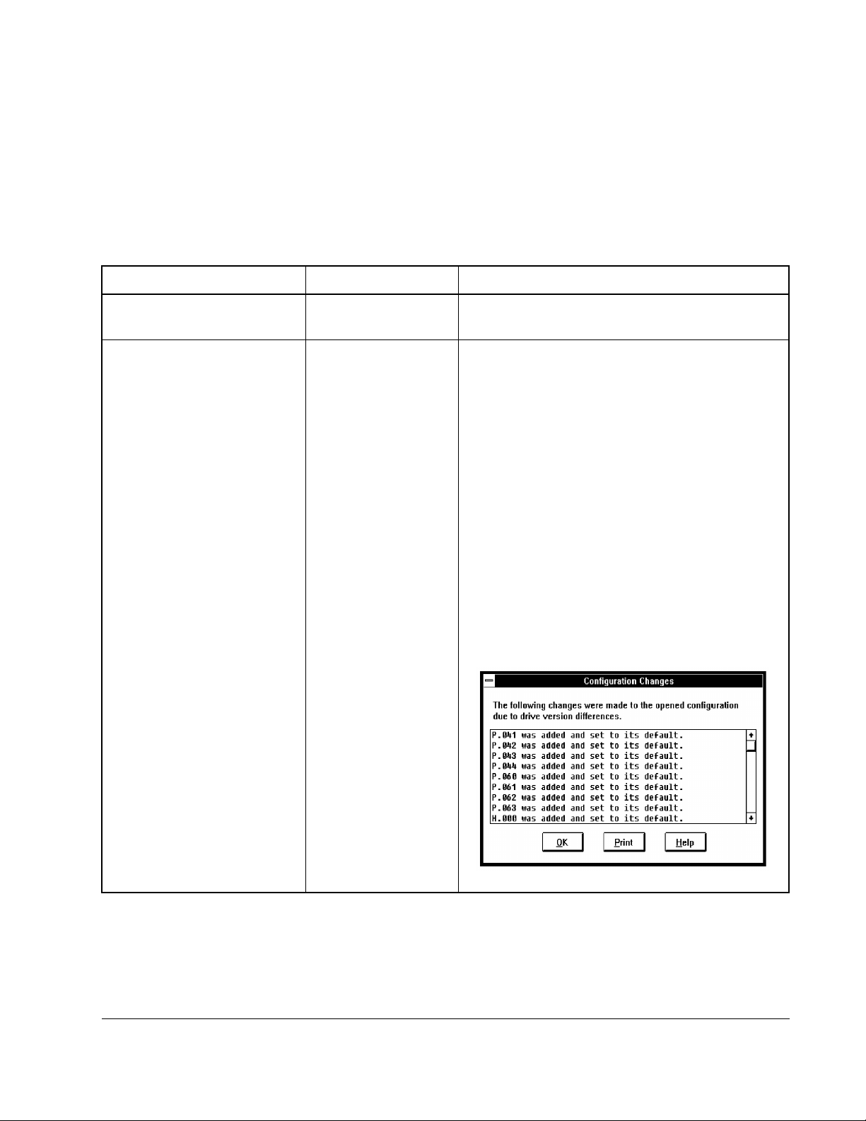
If parameter differences are found, the CS3000
software replaces the parameters in the copied
configuration to match the parameters of the
currently selected drive version. The Configuration
Changes dialog box is displayed, which shows you
what changes were made. This dialog box cannot
be edited.
Configuring the Drive
3-5
Page 30
When parameter difference are found, the CS3000 software makes the following
changes to parameters in the configuration file:
If the: Then:
selected drive is a later version than the drive
for which the configuration file was created
selected drive is an earlier version than the
configuration file
parameter range changed between versions
of the drive and the parameter is set to a value
that is out of range for the selected drive
From the Configuration Changes dialog box, you can print the changes, save the
changes to a file for reference, or simply review the changes and return to the main
window.
To: Do the following:
review the changes Use the scroll bar to view the list
print the changes Choose Print.
• Parameters are added if they did not exist in the earlier
drive. These parameters are set to default values.
• Parameters that existed in the earlier file might be set
to defaults if some of the options for the parameter did
not exist in the earlier drive version.
• Parameters are deleted if they do not exist in the
earlier drive version.
• A parameter value that is too high is set to the
maximum allowed for the selected drive.
• A parameter value that is too low is set to the minimum
value allowed for the selected drive.
The standard Windows Print dialog box is
displayed
3-6
save the changes to a file that can
be viewed by an editor such as
Windows Notepad
return to the main window from
the Configuration Changes dialog
box
Step 1. Choose Print.
Step 2. Select the Print to File checkbox.
Step 3. Choose OK.
The Print Configuration Changes to
File dialog box is displayed, which is
the same as the Save dialog box.
Step 4. Specify a directory, file name, and
extension.
Step 5. Choose OK.
Choose OK.
When you return to the main window, the
opened configuration is shown as
“UNTITLED.” The original configuration file is
not changed. To save the new configuration,
see section 3.6.
Control and Configuration Software V6.1
Page 31

3.5 Editing a Configuration
You can edit the opened configuration using the Configuration Editor. When the editor
is started, the software makes a copy of the opened configuration for you to work on.
This gives you the option of either saving or ignoring the changes when you exit the
Configuration Editor.
To access the Configuration Editor:
• From the Config menu, choose edit, or click .
Figure 3.4 shows a sample Configuration Editor
Configuring the Drive
Figure 3.4 – Configuration Editor
The parameters shown in the Configuration Editor are the ones that you can modify
and download to the drive or save to a configuration file. Only retentive input
parameters appear in the Edit dialog box.
3.5.1 Assigning Parameter Values
Use the Configuration Editor to change parameter values. You can change values by
doing one of the following:
• Select the parameter you want to change and choose the Assign button.
• Select the parameter you want to change and edit the parameter directly.
• Double-click on the parameter.
3-7
Page 32
Move between parameter values in the editor by:
• clicking the values themselves
• using the scroll bar
• pressing the [Tab], [PgUp], [PgDn], or arrow keys
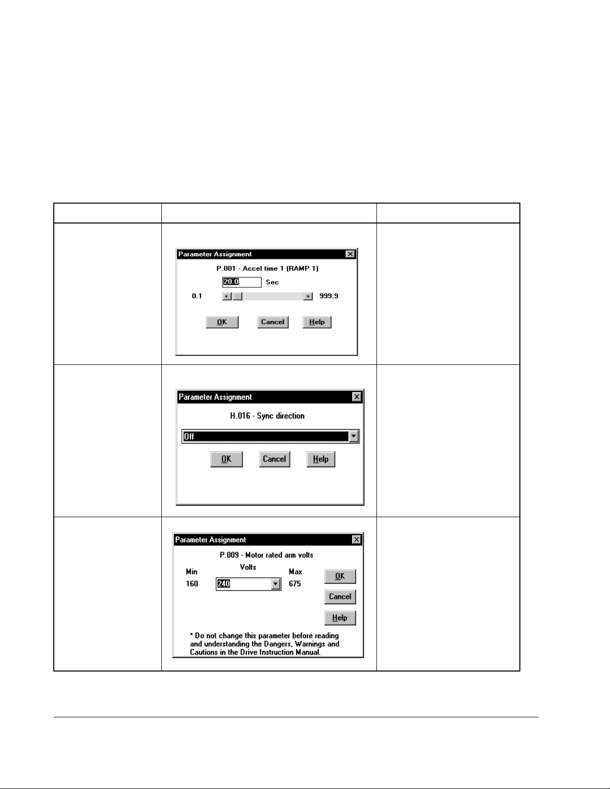
When you select Assign or double-click on a parameter, a Parameter Assignment
dialog box is displayed. The options in this dialog box depend on the options for the
parameter.I
If the parameter: The dialog box looks like this: Do the following:
can be set to any
value within a range
Enter the value in the box or
change the value by using the
scroll bar.
has limited options Click the arrow and select
from the options.
can be set through
the options or by
selecting a value
within a range
3-8
Click the arrow and select
from the options, or enter the
value in the box.
Control and Configuration Software V6.1
Page 33
Important: If you change a drive’s control type parameter (for example, vector or
volts/hertz for GV3000 drives), a message is displayed notifying you that
changing the control type will reset parameters to their default values and
prompting you to continue. If you select Yes to continue, the parameter list
is changed to show only parameters that are relevant for the new control
type, and parameters in the Editor are set to defaults. These changes only
affect the configuration in the Editor.
Selecting OK in the Parameter Assignment dialog box sets the selected parameter
value and exits the dialog box. Cancel ignores any changes and exits the dialog box.
3.5.2 Ending an Editing Session
When you have finished editing parameters, select OK from the Configuration Editor
to write the values of the edited parameters into the opened configuration. You should
then use the Save command from the File menu to save the edited configuration file to
disk.
If you select Cancel from the Configuration Editor, a message is displayed prompting
you to ignore the changes or accept them. If you ignore the changes, any new
parameter values entered during the editing session are ignored, and the session
ends.
3.5.3 Entering and Editing a Configuration Description
You can add a description to a configuration file that documents information you want
to convey about the configuration. The configuration description appears in the main
window under the name of the opened configuration and on printouts of the
configuration.
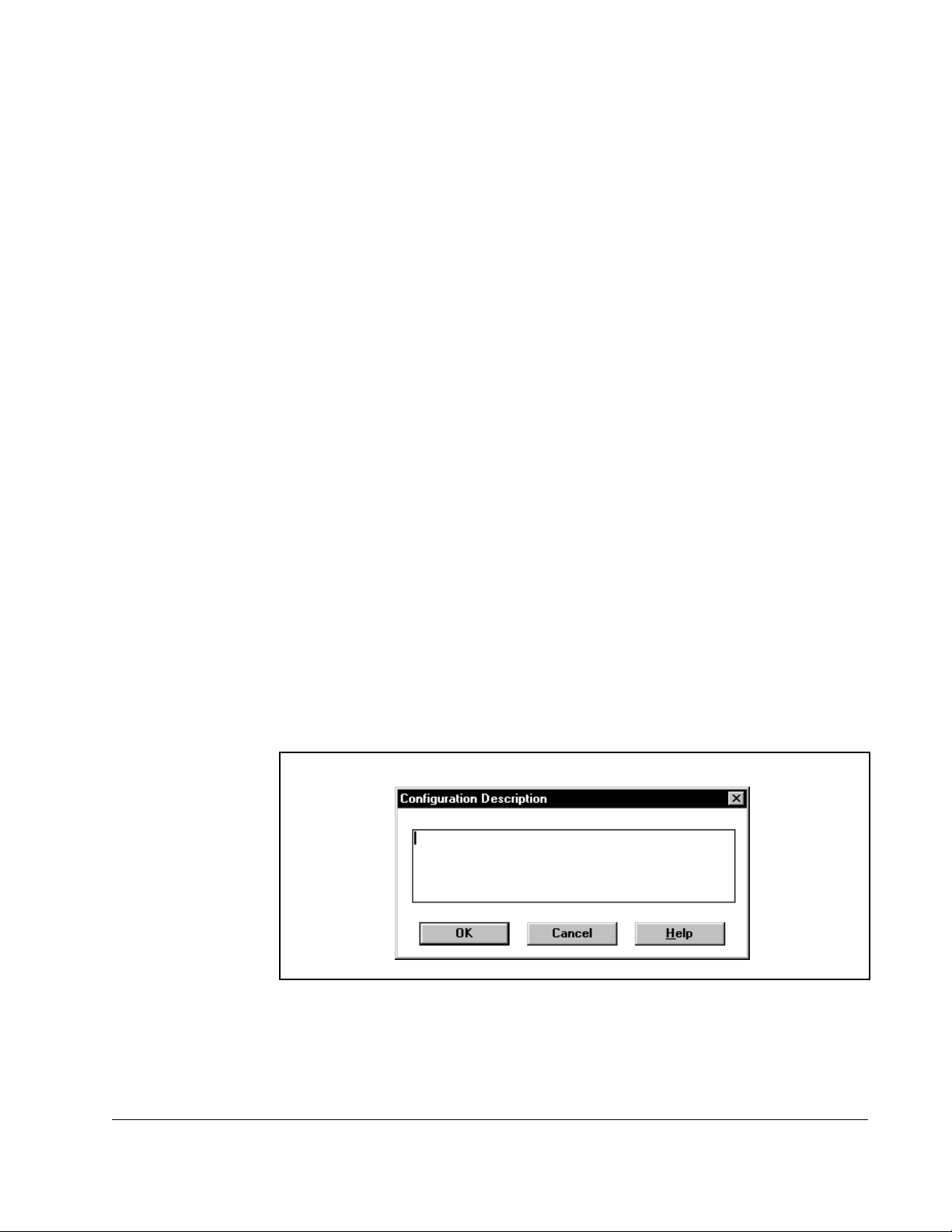
To enter or edit a configuration description:
Step 1. From the Config menu, choose Description.
The Configuration Description dialog box appears as shown in figure 3.5.
Figure 3.5 – Configuration Description Dialog Box
Step 2. Type in new text or edit and existing description. See table 3.1 for editing tips.
Step 3. Save your edits and close the dialog box by clicking OK
Configuring the Drive
3-9
Page 34
.
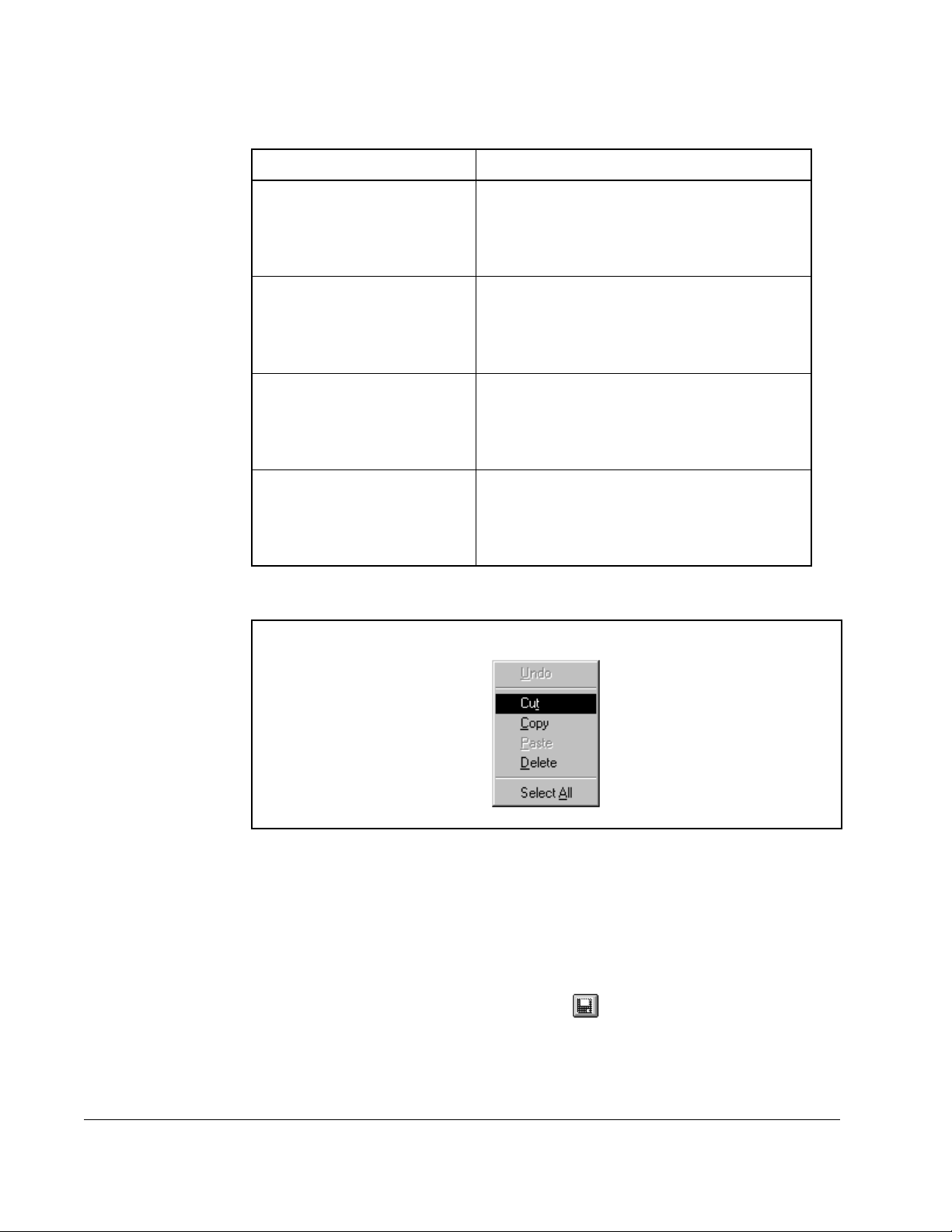
Table 3.1 – Editing Configuration Descriptions
To: Do the following:
cut text Step 1. Select the text.
Step 2. Press the right mouse button, and
choose Cut from the pop-up menu
(see figure 3.6), or press [Ctrl + x].
paste text Step 1. Select the text.
Step 2. Press the right mouse button, and
choose Paste from the pop-up menu
(see figure 3.6), or press [Ctrl + v].
copy text Step 1. Select the text.
Step 2. Press the right mouse button, and
choose Copy from the pop-up menu
(see figure 3.6), or press [Ctrl + c].
delete text Step 1. Select the text.
Step 2. Press the right mouse button, and
choose Delete from the pop-up menu
(see figure 3.6), or press [Delete].
3-10
Figure 3.6 – Configuration Description Pop-Up Edit Menu
3.6 Saving a Drive Configuration
Saving a file writes the open drive configuration to the configuration file that is shown
in the main window. This writes over the configuration file shown in the main window.
To save a file:
• From the File menu, choose Save, or click .
If the configuration file is “Untitled,” the Save Configuration File dialog box is
displayed. Refer to section 3.7 for more information.
Control and Configuration Software V6.1
Page 35
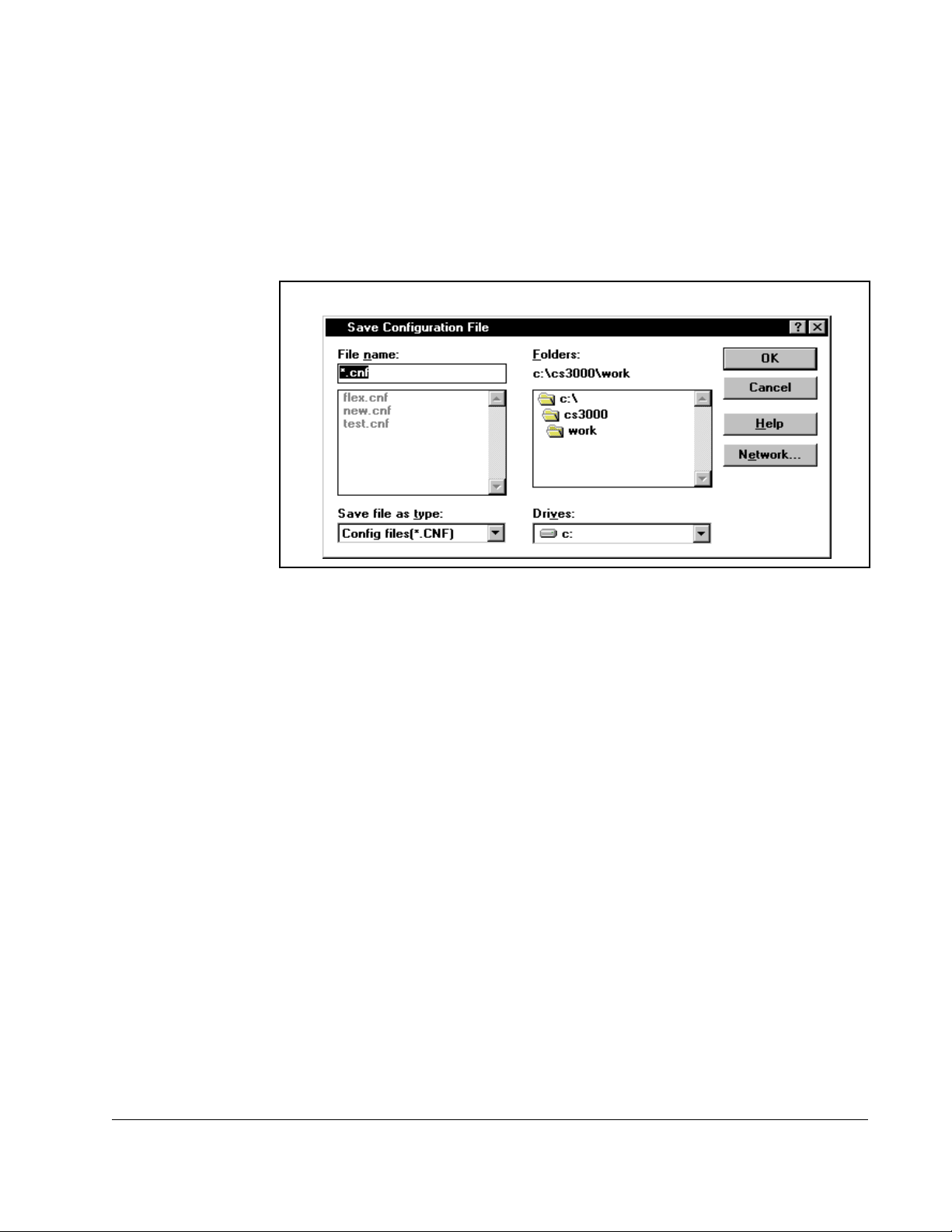
3.7 Saving the Open Drive Configuration to Another File
You can write the open drive configuration to a configuration file other than the one
shown in the main window. To do this:
Step 1. From the File menu, choose Save As.
The Save Configuration File dialog box is displayed, as shown in figure 3.7
Figure 3.7 – Save Configuration Dialog Box
Step 2. Select the drive and directory where you want to store the configuration.
Selecting Network lets you access any mapped network drive.
Step 3. Specify the file name in the File Name field. Configuration file names must be
eight alphanumeric characters or fewer. The file name should have the
extension .CNF.
Step 4. Select OK to save the file. Select Cancel to close the dialog box without
saving.
Configuring the Drive
3-11
Page 36

3.8 Printing a Configuration
You can send a copy of the open configuration to a printer or to a text file. The printout
lists the configuration parameters and their assigned values.
To print a configuration:
• From the File menu, choose Print, or click .
The standard Windows Print dialog box. The Selection and Pages options are always
grayed (non-selectable)
Figures 3.8 shows a sample prin tout .
Drive type: GV3000 V4.0
Configuration: UNTITLED - V/Hz
Prm Value Units Description
P.001 20.0 Sec Accel time 1 (RAMP 1)
P.002: 20.0 Sec Decel time 1 (RAMP 1)
P.003: 5.0 Hertz Minimum speed
P.004: 60.0 Hertz Maximum speed
P.005: 100 % Current limit
P.007: 0 TB digital inputs config
P.008: Analog TB speed ref sel
P.009: 0 TB analog input offset
P.010: 1.000 TB analog input gain
P.011: Off TB analog input invert
P.012: SpdBi TB analog output source
P.013: Fault Output relay config
P.014: None Trim ref. source select
P.015: 0.0 % Trim gain percentage
P.016: 0.0 % Draw gain percentage
P.017: 20.0 Sec Accel time 2 (RAMP 2)
P.018: 20.0 Sec Decel time 2 (RAMP 2)
P.019: On S-Curve Enable
P.020: 5.0 Hertz Jog speed reference
P.021: 20.0 Sec Jog ramp accel time
P.022: 20.0 Sec Jog ramp decel time
P.023: 20.0 Sec MOP accel/decel time
P.024: IET MOP reset configuration
P.025: COAST Stop mode
P.026: IET Func loss type mode
P.027: Off Reverse disable
P.028: 1800 RPM display scaling
P.029: 0 Elapsed time meter
P.030: Off Reverse disable
P.031: 5.0 Hertz Multispeed preset 1
P.032: 5.0 Hertz Multispeed preset 2
P.033: 5.0 Hertz Multispeed preset 3
P.034: 5.0 Hertz Multispeed preset 4
P.035: 5.0 Hertz Multispeed preset 5
P.036: 5.0 Hertz Multispeed preset 6
P.037: 5.0 Hertz Multispeed preset 7
P.038: 5.0 Hertz Multispeed preset 8
P.040: On Motor overload enable
P.041: FrcCool Motor overload type
P.042: 5.0 Sec Line dip ride thru time
P.043: 0 Fault auto reset counts
P.044: 8 Sec Fault auto reset time
P.047: 8 kHz Carrier frequency (kHz)
P.048: V/HZ Controller type select
P.049: USA Country default select
P.060: 1 Network drop number
P.061: Basic Network connection type
P.062: IET Option: comm loss select
P.063: Direct Option: ref source select
P.065: 0.000 Option: type and version
P.095 0.0 Amps Power module output amps
P.098 0.00 Software version number
P.099 UnSel Power module type
3-12
Figure 3.8 – Sample Configuration File Printout
Control and Configuration Software V6.1
Page 37

Uploading and Downloading Drive
This chapter describes how to upload, download, and compare drive configurations.
4.1 Uploading a Drive Configuration
You can upload the drive configuration from the connected drive to the personal
computer.
To upload a configuration:
Step 1. Make sure the personal computer is connected to the drive. Refer to sections
2.3 and 3.1 if you need instructions for connecting the personal computer to a
drive.
Step 2. From the Config menu, choose Upload or click .
CHAPTER 4
Configurations
Step 3. If a drive configuration is already opened, you are prompted to save that
configuration to a file. The open configuration (if any) is replaced by the
uploaded drive configuration.
After uploading the drive configuration, the open configuration is displayed as
“UNTITLED.”
Uploading and Downloading Drive Configurations
4-1
Page 38

4.2 Downloading a Configuration to the Drive
You can copy the opened configuration currently in the CS3000 software to the
connected drive.
ATTENTION:The download command replaces the parameter values in
the drive with the parameter values from the open configuration. Only
!
Important: If FlexPak 3000 parameter changes are disabled by the drive’s Program
To download an opened configuration to the connected drive, follow these steps:
Step 1. Make sure the personal computer is connected to the drive. Refer to sections
Step 2. Make sure the drive is stopped before downloading a configuration to the
Step 3. From the Config menu, choose Download, or click .
qualified personnel should develop and download drive configurations.
Read and understand the drive instruction manual in its entirety before
downloading a configuration. Failure to observe this precaution could
result in severe bodily injury or loss of life.
Protection jumper (J16), you cannot write parameters to the drive.
2.3 and 3.1 if you need instructions for connecting the personal computer to a
drive.
drive.
Step 4. If the downloaded configuration contains parameter values that are out of
range for the drive, the software on the drive modifies these parameter
values to bring them within allowed ranges. If this occurs, a Download
Configuration Changed dialog box is displayed. This dialog box displays the
differences between the downloaded configuration and the configuration
currently in the drive. The software prompts you to specify if the changes
made in the drive should also be made to the configuration in the CS3000
software. To update the opened configuration, select Yes. To not update the
configuration, select No.
4-2
Control and Configuration Software V6.1
Page 39

4.3 Comparing the Drive Configuration to th e Opened Configuration
You can compare all of the parameter values in the opened configuration with the
parameter values in the drive. For drives with more than one control type (for example,
volts/hertz and vector), only parameters that are relevant to the selected control type
are compared.
To compare the parameters in an open configuration with those on the drive, follow
these steps:
Step 1. Make sure the personal computer is connected to the drive. Refer to sections
2.3 and 3.1 if you need instructions for connecting the personal computer to a
drive.
Step 2. From the Config menu, choose Compare Drive.
Parameters with different values are shown in a dialog box. Table 4.1 lists
actions you can perform in the Compare dialog box.
Table 4.1 – Compare Dialog Box Functions
To: Do the following:
Exit the Compare dialog box Choose OK.
Print the list of changes Choose Print.
The standard Windows Print dialog box is
displayed.
Save the list of changes to a file that
can be viewed by an editor such as
the Windows Notepad
Step 1. Select Print. The standard
Windows Print dialog box is
displayed.
Step 2. Select the Print to File checkbox.
Step 3. Se le ct OK .
The Print Differences to File
dialog box is displayed. This
dialog box is the same as the
Save dialog box.
Step 4. Specify a directory, file name,
and extension, and click OK.
Uploading and Downloading Drive Configurations
4-3
Page 40
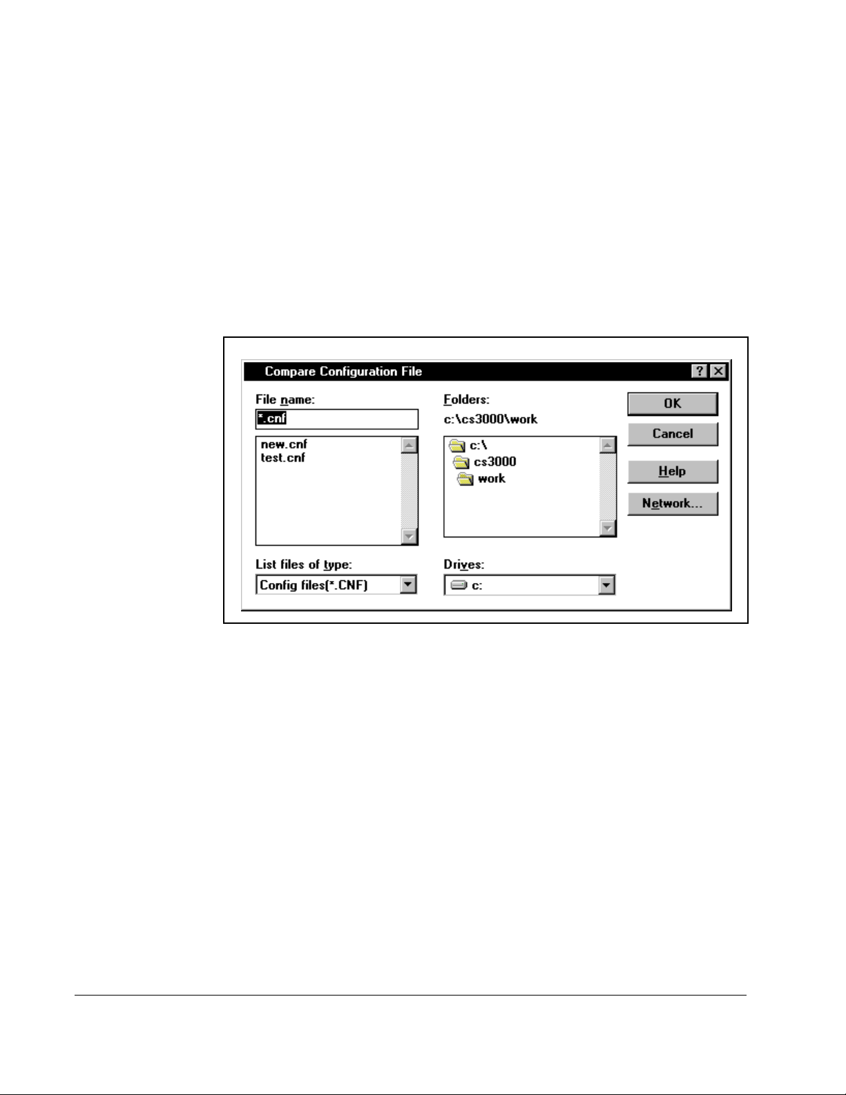
4.4 Comparing the Parameter Values in the Opened Configuration with Those in Another Conf iguration File
You can compare the parameter values in the opened configuration with those
parameter values in another configuration file. To do this:
Step 1. Make sure the configuration file to be compared is opened.
Step 2. From the Config menu, choose Compare File.
The Compare Configuration dialog box is displayed as shown in Figure 4.1.
4-4
Figure 4.1 – Compare Configuration File Dialog Box
Step 3. Use the dialog box to specify the file that you want to compare with the
opened configuration file. Use the Network button to access network drives.
Step 4. Begin the comparison by clicking OK.
Control and Configuration Software V6.1
Page 41

Parameters with different values are shown in a dialog box similar to the one
shown in figure 4.2. Table 4.2 lists actions you can perform in the
Configuration Differences dialog box.
Figure 4.2 – Configuration Differences Dialog Box
Table 4.2 – Configuration Differences Dialog Box Options
To: Do the following:
Exit the Compare dialog box Choose OK.
Print the list of changes Choose Print.
The standard Windows Print dialog box is displayed.
Save the list of changes to a file that can
be viewed by an editor such as the
Windows Notepad
Step 1. Select Print. The standard Windows Print dialog box
is displayed.
Step 2. Select the Print to File checkbox.
Step 3. Select OK.
The Print Differences to File dialog box is displayed.
This dialog box is the same as the Save dialog box.
Step 4. Specify a directory, file name, and extension, and
click OK.
Uploading and Downloading Drive Configurations
4-5
Page 42

4-6
Control and Configuration Software V6.1
Page 43

CHAPTER 5
Tuning GV3000 and Liqui-Flo
Vector Drives
Important: The drive tuning functions are available only for GV3000 and Liqui-Flo
drives using vector regulation. If you have a GV3000 or Liqui-Flo drive
using volts/hertz regulation, or a FlexPak 3000 drive, you cannot use
these functions.
The drive tuning functions aid in the setup of drive tuning parameters. You should set
up the drive (except the drive tuning parameters) before performing drive tuning. You
should also save your drive configuration before tuning the drive. The drive must be
connected to the motor to perform some of these functions and the motor nameplate
information must be entered correctly.
These functions are selected under Drive|Tuning in the CS3000 main menu. If the
drive tuning functions are not supported for the selected drive, the menu item is
grayed.
When Drive|Tuning is selected from the CS3000 main menu, the menu appears as
follows:
Section 5.1 describes saving the drive configuration. Sections 5.2 and 5.3 describe
how to perform Standard tuning and Custom tuning for GV3000 and Liqui-Flo vector
drives.
Tuning GV3000 and Liqui-Flo Vector Drives
Figure 5.1 – Drive Tuning Menu
5-1
Page 44
5.1 Saving the Drive Configurat ion Before Tuning
Some of the tuning tests temporarily modify drive parameters in order to run the test. If
the test completes normally, the drive tuning procedure restores the values of these
parameters. If power is lost, or if communication between the personal computer and
the drive is lost, the original parameter settings in the drive could be lost. Before
beginning the Standard tuning or Custom tuning procedures, you are prompted to
upload the drive configuration (the same as described in section 4.1) and save it in a
file (the same as described in section 3.7). If needed, this saved configuration can be
downloaded to the drive to restore its configuration.
5.2 Using Standard Tuning
Standard tuning is designed for applications with normal performance requirements.
The tuning process is largely automatic. You will be presented a series of simple
dialog boxes or message boxes that explain each step, and will be prompted to verify
and accept the system-generated values.
ATTENTION:This equipment is at line voltage when AC power is
connected. Disconnect and lockout all ungrounded conductors of the AC
!
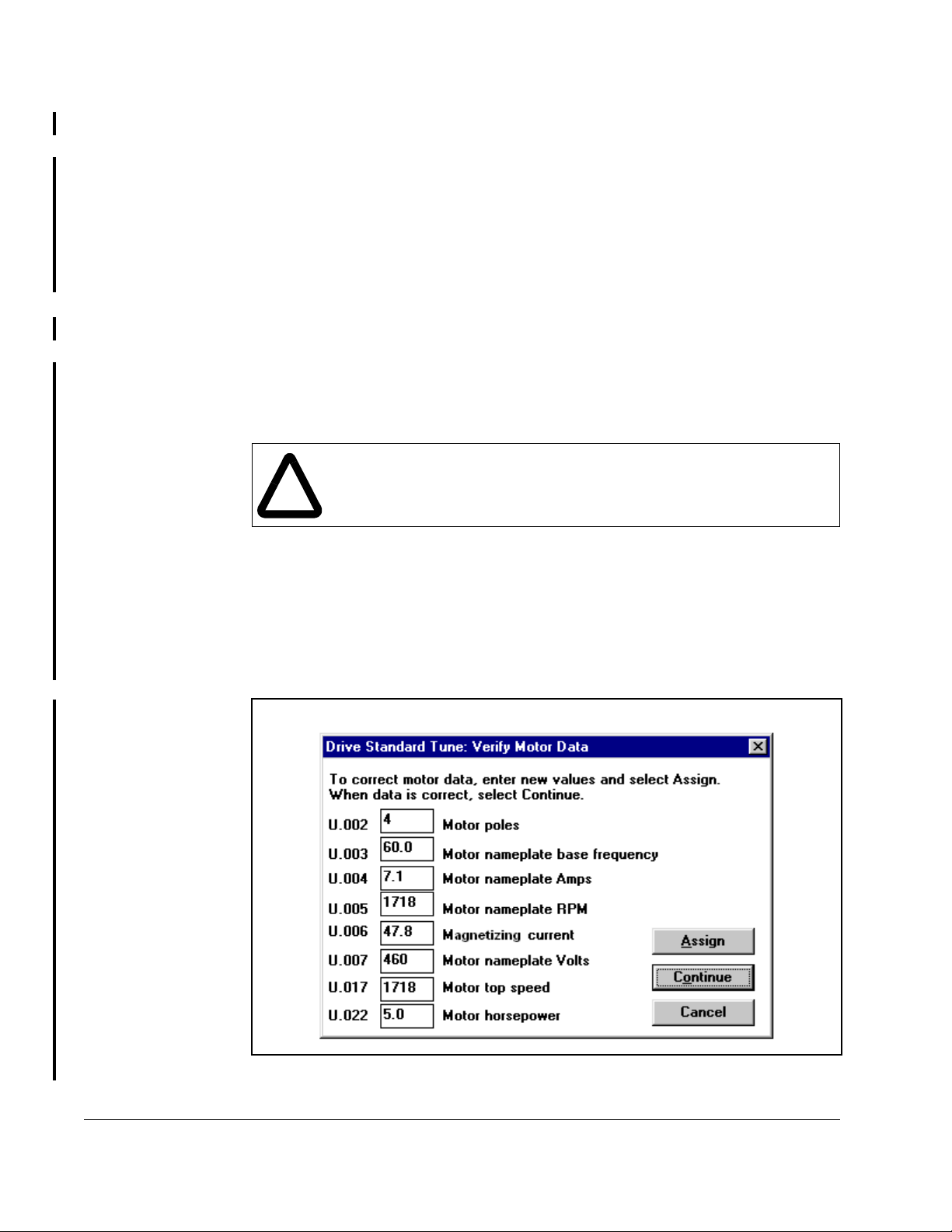
When Standard is selected, the Motor Data dialog box will be displayed as shown in
figure 5.2. The values displayed are read from the drive.
power line before working on the unit. Failure to observe this precaution
could result in severe bodily injury or loss of life.
The steps below appear in the order that the dialog boxes appear.
Important: Before beginning this procedure, make sure that the motor is connected
to the drive and, if possible, disconnected from the load.
5-2
Figure 5.2 – Example of Motor Data Dialog Box
Control and Configuration Software V6.1
Page 45

ATTENTION:The setting of parameters U.001 (Encoder PPR), U.002
(Motor Poles), U.003 (Motor Nameplate Base Frequency), U.005 (Motor
!
Step 1. Verify Motor Data - The motor nameplate data parameter values are
Step 2. Measure Magnetizing Current - A message box with the magnetizing
Nameplate RPM), and U.017 (Motor Top Speed) determines the motor
maximum speed. These parameters must be set by a qualified person
who understands the significance of setting them accurately. Failure to
observe this precaution could result in bodily injury.
displayed.
a. Enter new values as needed. Press Assign to write the values to the drive.
b. Press Continue when all values are correct.
current value is displayed.
a. Click No to use the displayed value (and skip to step 3) or click Yes to
measure the magnetizing current. If measure magnetizing current is
selected, the following message is displayed:
“The load must be uncoupled from the motor shaft to run this test. If the
load is not uncoupled, the test results may be incorrect. Select OK when
you are ready to run the test or Cancel to quit.”
b. Lock out and tag all power to the drive and its load.
c. Disconnect the load from the motor shaft.
d. Remove the lockout and reapply power to the drive.
e. Click OK. The following message is displayed:
“Warning:
When OK is selected, the motor will accelerate gradually to 90% of base
speed. The acceleration and deceleration times will be about 30 seconds.
Select OK to begin the test or Cancel to quit.”
f. Click OK to start the motor, accelerate to 90% of base speed, and
measure the magnetizing current.
g. When the measurement is complete, click OK to continue. (Note that, if the
self-tune fails, a message box containing an error message is displayed.)
Step 3. Calculate Torque and Flux gains - Torque and flux current gains are
calculated (using the magnetizing current value and motor nameplate data)
and are displayed.
Click Yes to write the displayed values to the drive, or click No if you do not
want the calculated torque and flux gains written to the drive.
Step 4. Measure Inertia - The following message is displayed:
“The load must be coupled to the motor shaft before running this test. If the
load is not coupled, the test results will be incorrect. Select OK when you are
ready to begin this test or Cancel to quit.”
a. Lock out and tag all power to the drive and its load.
b. Connect the load to the motor.
Tuning GV3000 and Liqui-Flo Vector Drives
5-3
Page 46

c. Remove the lockout and reapply power to the drive.
d. Click OK. The following message is displayed:
“Warning:
This test will set Current Limit (P.005) to the Magnetizing Current (U.006)
plus 20%. The motor will be run at 10% of synchronous speed for several
seconds and then step to 95% of synchronous speed. Select OK to begin
the test or select Cancel to quit.”
e. Click OK to start the motor and accelerate to 95% of synchronous speed.
f. The drive will run the motor and driven machinery to measure inertia.
g. When the measurement is complete, click OK to continue.
Step 5. Calculate Speed Loop Gains - The proportional and integral gains are
calculated using default values.
Click Yes to write the displayed values to the drive (U.012 and U.013), or click
No to leave the values in the drive unchanged.
This completes the Standard tuning process.
5-4
Control and Configuration Software V6.1
Page 47

5.3 Using Custom Tuning
Custom tuning opens a drive tuning dialog box with more advanced tuning features. It
is intended for applications requiring a high degree of performance.
ATTENTION:This equipment is at line voltage when AC power is
connected. Disconnect and lockout all ungrounded conductors of the AC
!
The custom drive tuning dialog box consists of four areas. You can move from area to
area by clicking the appropriate radio button. The areas are:
• Motor data
• Torque/Flux
• Speed Loop
•Profile
Important: Before beginning this procedure, make sure that the motor is connected
5.3.1 Setting Motor Data
Motor nameplate data can be viewed or changed. When you select Motor Data, the
Drive Tuning dialog box is displayed with motor data values read from the drive.
Figure 5.3 provides an example of the Motor Data dialog box.
power line before working on the unit. Failure to observe this precaution
could result in severe bodily injury or loss of life.
to the drive and, if possible, disconnected from the load.
Tuning GV3000 and Liqui-Flo Vector Drives
Figure 5.3 – Example of Setting Motor Data Values
5-5
Page 48
ATTENTION:The setting of parameters U.001 (Encoder PPR), U.002
(Motor Poles), U.003 (Motor Nameplate Base Frequency), U.005 (Motor
!
Use the following procedure to set the motor nameplate values.
Step 1. Click a parameter value and enter a new value to change the value of any of
Step 2. Click Assign to write the motor data values to the drive.
Nameplate RPM), and U.017 (Motor Top Speed) determines the motor
maximum speed. These parameters must be set by a qualified person
who understands the significance of setting them accurately. Failure to
observe this precaution could result in bodily injury.
the displayed parameters.
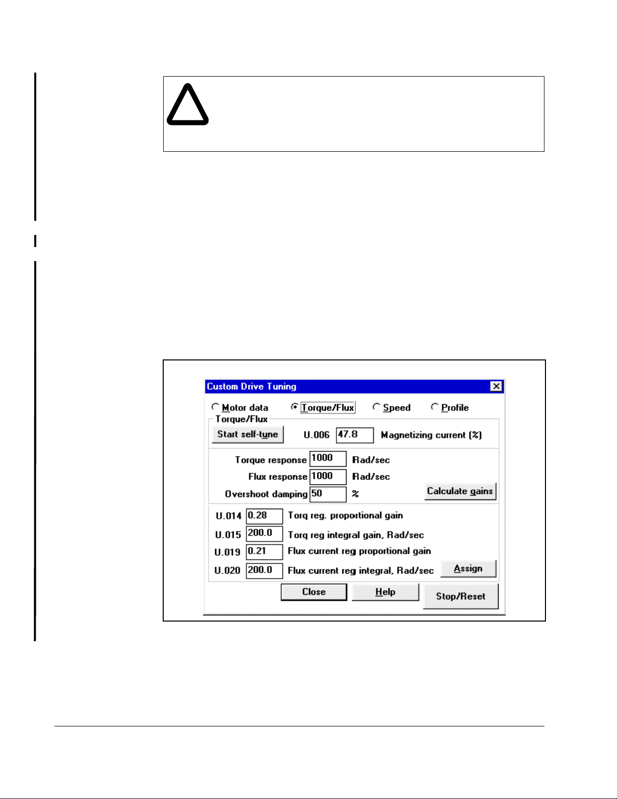
5.3.2 Tuning the Torque/Flux Loop
The torque/flux loop is tuned by using the motor nameplate data, the magnetizing
current value in U.006, and calculating the values for U.014, U. 015, U.019, and U.020
using the torque response, flux response, and overshoot damping values.
When you select Torque/Flux, the Drive Tuning dialog appears with torque/flux loop
data values read from the drive. Figure 5.4 provides an example of the Torque/Flux
Loop dialog box.
5-6
Figure 5.4 – Example of Setting Torque/F lux Loop Data Values
Control and Configuration Software V6.1
Page 49

Use the following procedure to tune the Torque/Flux Loop.
Step 1. If the magnetizing current is known, enter the value for U.006 (Magnetizing
Current), or accept the displayed value. Continue to step 2.
or
a. Click Start Self-Tune. The following message is displayed:
“The load must be uncoupled from the motor shaft to run this test. If the
load is not uncoupled, the test results may be incorrect. Select OK when
you are ready to run the test or Cancel to quit.”
b. Lock out and tag all power to the drive and its load.
c. Disconnect the load from the motor shaft.
d. Remove the lockout and reapply power to the drive.
e. Click OK. The following message is displayed:
“Warning:
When OK is selected, the motor will accelerate gradually to 90% of base
speed. The acceleration and deceleration times will be about 30 seconds.
Select OK to begin the test or Cancel to quit.”
f. Click OK to start self-tune.
The drive is run with Torque Self-Tune Enabled (U.008) to establish the value
for the Magnetizing Current (U.006). The display will indicate that self-tune is
in progress and that the drive is running.
If an error occurs, Torque Self-Tune Result (U.009) is read and an
appropriate error message is displayed.
Step 2. Enter values for torque response, flux response and overshoot damping, or
accept the displayed default values.
Torque response is the torque crossover frequency.
Flux response is the flux crossover frequency.
Overshoot damping is a value from 20 to 100, where 20 is the least amount
of damping and yields the greatest overshoot to a step in reference, and 100
is the highest amount of damping and yields the least overshoot.
Step 3. Click Calculate Gains.
If any of these values is out of range, the valid range is displayed and the
cursor appears on the field containing the error.
The entered response values, the overshoot damping value, and motor data
are used to calculate U.014, U.015, U.019 and U.020.
The values for U.014, U.015, U.019 and U.020 will be displayed.
Step 4. Click Assign to write the torque/flux loop data to the drive.
5.3.3 Tuning the Speed Loop
The speed loop is tuned by adjusting the speed loop proportional and integral gains
(U.012 and U.013). Speed loop tuning is a function of the inertia and desired
bandwidth. The inertia of the motor and connected load can be set manually if known.
When you select Speed, the Drive Tuning dialog box appears as shown in figure 5.5.
Tuning GV3000 and Liqui-Flo Vector Drives
5-7
Page 50

Figure 5.5 – Example of Setting Speed Loop Data Values
Use the following procedure to tune the Speed Loop.
Step 1. Enter the inertia value for the motor and load in the Lb-Ft**2 box. Continue to
step 2.
or
a. Click Start Self-Tune. The following message is displayed:
“The load must be coupled to the motor shaft before running this test. If the
load is not coupled, the test results will be incorrect. Select OK when you
are ready to begin this test or Cancel to quit.”
b. Lock out and tag all power to the drive and its load.
c. Connect the load to the motor.
d. Remove the lockout and reapply power to the drive.
e. Click OK. The following message is displayed:
“Warning:
This test will set Current Limit (P.005) to the Magnetizing Current (U.006)
plus 20%. The motor will be run at 10% of synchronous speed for several
seconds and then step to 95% of synchronous speed. Select OK to begin
the test or select Cancel to quit.”
5-8
f. Click OK to start the motor and accelerate to 95% of base speed.
g. The drive will run the motor and driven machinery to measure inertia.
h. When the measurement is complete, click OK to continue.
Control and Configuration Software V6.1
Page 51
Step 2. Enter the desired speed response and overshoot damping values.
Step 3. Click Calculate Gains. The speed loop proportional gain (U.012) and integral
gain (U.013) are calculated from speed response, overshoot damping
percentage, inertia, horsepower, rated RPM, and top RPM.
You can also manually modify U.012 and/or U.013 by clicking on either
parameter and then entering a new value.
Step 4. Click Assign to write the speed loop data to the drive.
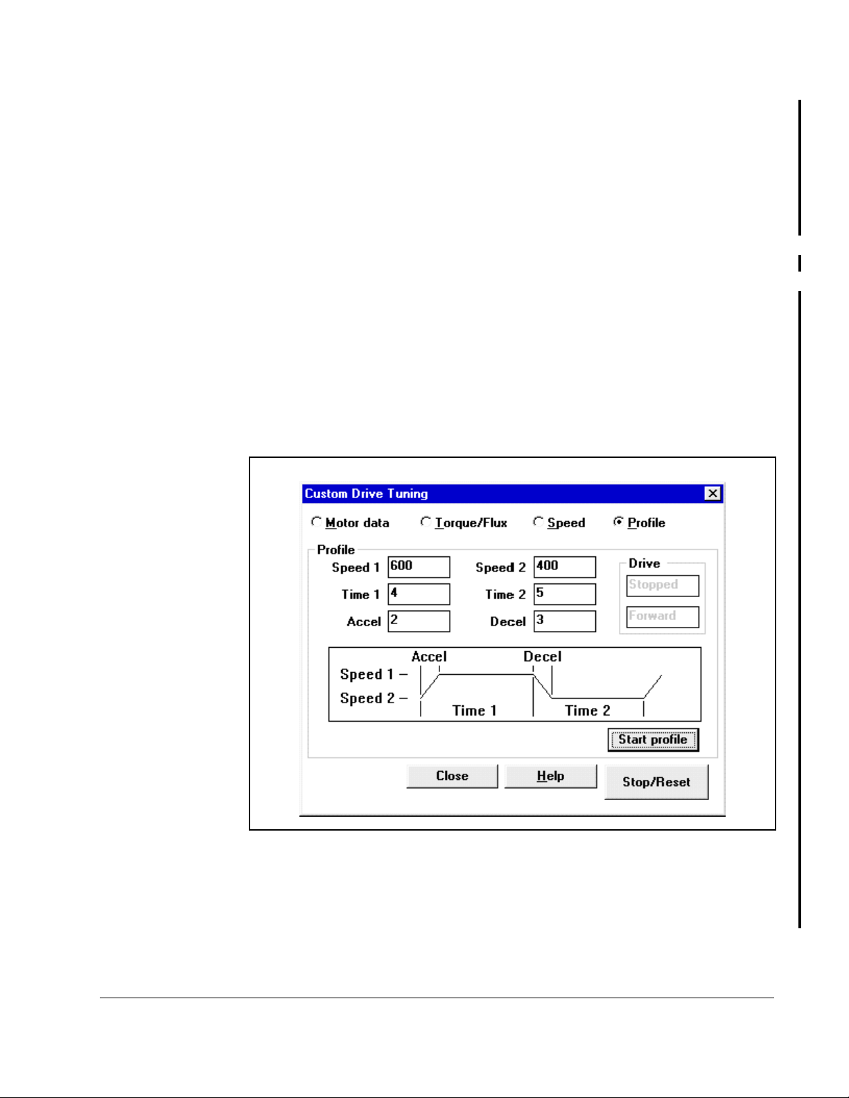
5.3.4 Using the Profile Feature To Check Drive Tuning
You can use the speed profile generator to facilitate tuning verification and adjustment
of drive tuning. Once started, the speed profile generator will alternate between two
speed setpoints. You can specify the speed setpoints, acceleration time, deceleration
time, and duration at each setpoint. The speed versus time diagram in the profile
dialog box, as shown in figure 5.6, indicates how the six profile variables are applied.
After starting the profile, the PC Scope feature can be used to monitor torque and/or
speed response to verify or fine-tune the response as desired.
When you select Profile, the Drive Tuning dialog box appears as shown in figure 5.6.
Use the following procedure to check drive tuning.
Step 1. Verify that the load is connected to the motor shaft.
Step 2. Enter values for Speed 1 and 2, Time 1 and 2, Accel and Decel.
Tuning GV3000 and Liqui-Flo Vector Drives
Figure 5.6 – Drive Profile Example
5-9
Page 52

Step 3. Click Start Profile. The following message is displayed:
“Profile will run the motor alternating between xxx RPM for x.x sec and
xxx RPM fo r x.x sec. Acce lerat ion ti me is x.x se c, de celer ation t ime i s x.x sec .
Select OK to run the motor using this profile, or Cancel to quit.”
Step 4. Click Ok to start the profile.
The drive will cycle between Speed 1 and Speed 2, staying at each speed for
the amount of time entered for Time 1 and Time 2. Y ou can monitor results in
PC Scope (see chapter 9).
Step 5. Click Stop/Reset to stop the drive and the profile.
Some drive parameters (accel/decel) may be modified automatically in order
to run the profile. These values will be saved prior to being modified by this
function and the original values will be restored when Stop/Reset is selected.
This completes the Custom tuning process.
5-10
Control and Configuration Software V6.1
Page 53

Monitoring and Editing Drive
This chapter describes how to monitor and editor parameters using the Parameter
Monitor.
6.1 About the Parameter Monitor
Use the Parameter Monitor to view and edit parameter values in the connected drive.
You can also set up monitor lists to store your choices for future use. The Parameter
Monitor is not affected by and does not affect the opened configuration.
Important: If FlexPak 3000 parameter changes are disabled by the drive’s Program
Protection jumper (J16), you cannot write parameters to the drive.
You cannot change parameter values in the opened configuration uisng the Parameter
Monitor. To copy changes made in Monitor into the opened configuration, you must
upload the drive configuration from the drive (refer to chapter 4).
CHAPTER 6
Parameters
To access the Parameter Monitor, follow these steps:
Step 1. From the Drive menu, choose Parameter Monitor, or click .
A danger message is displayed.
Step 2. Make sure you understand this message, then select Continue to display the
Monitor window.
The first time you access the Parameter Monitor, the window is blank. Use the Add,
Remove, Assign, and Save buttons at the top of the window to create a parameter list
that can be saved for future use. See the following sections for information about using
these functions.
When parameters are displayed in the Parameter Monitor window, the parameter
values are updated periodically from the drive.
Monitoring and Editing Drive Parameters
6-1
Page 54
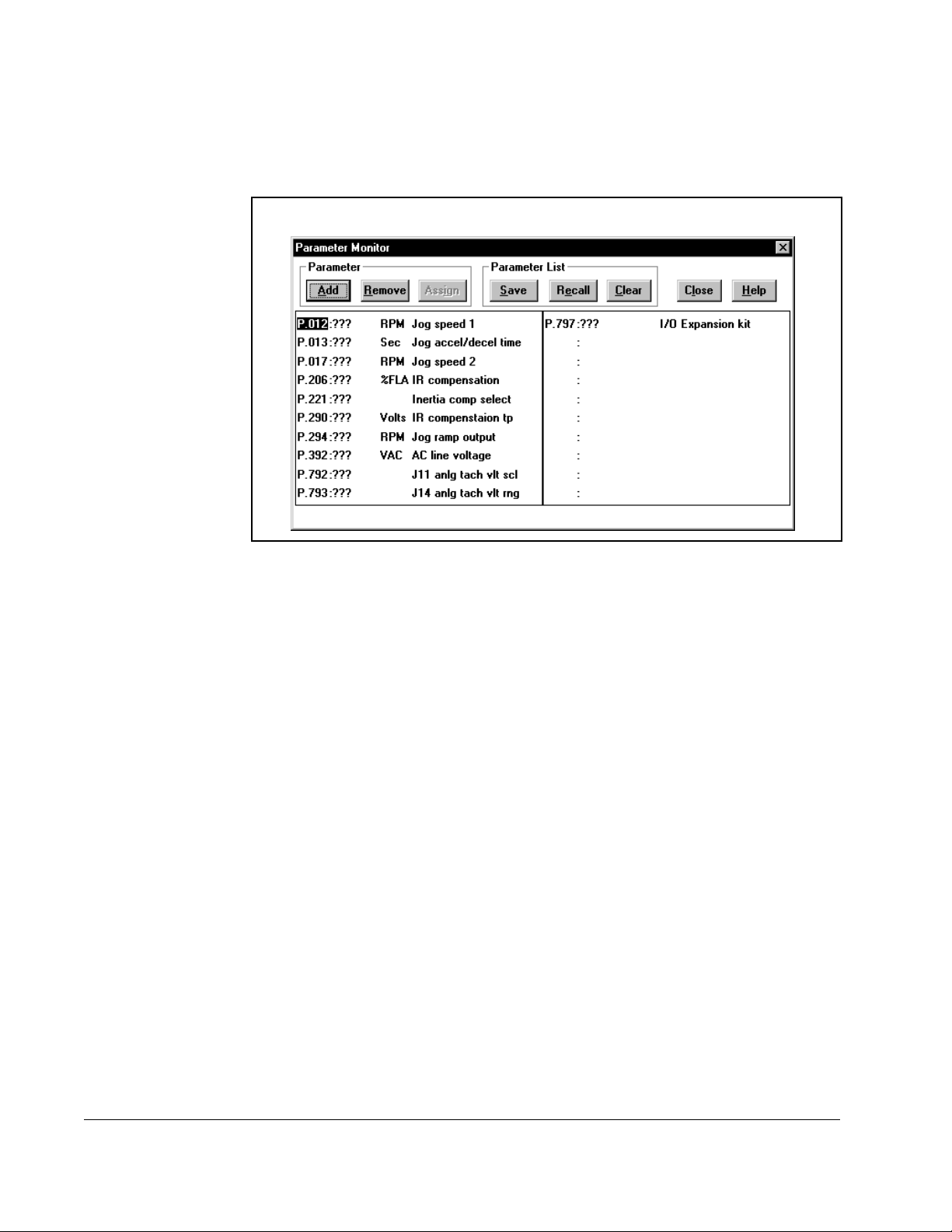
You can select a parameter shown in the Monitor window by clicking the parameter
name, or by using PgUp, PgDn, and the arrow keys. The Remove and Assign
functions work on the selected parameter. Figure 6.1 shows an example of the
Parameter Monitor window.
Figure 6.1 – Parameter Monitor Window
The sections that follow describe the functions available when using the CS3000
Parameter Monitor function.
6-2
Control and Configuration Software V6.1
Page 55

6.2 Adding Parameters to the Monito r List
You can add up to twenty parameters to the Monitor List. When you select Add, the
Add Parameters to Monitor List dialog box is displayed. The Sort By options let you
display the parameters by parameter number or by description (alphabetically). Figure
6.2 shows a sample Add Parameters to Monitor List dialog box.
Figure 6.2 – Add Parameters to Monitor List Dialog Box
To add parameters, follow these steps:
Step 1. Use the scroll bar or the arrow keys to move up and down the list of
parameters.
Step 2. Use the mouse or the spacebar to select the parameters you want to monitor.
You can select multiple parameters before choosing Add. You can select a
total of 20 parameters.
Step 3. Do one of the following:
• To add the parameters to the monitor list and continue to display the
dialog box, select Add.
• To add the parameters and return to the monitor window, select OK.
6.3 Removing Pa rame te rs from the Monitor List
To delete parameters from the Monitor List, follow these steps:
Step 1. Select the parameter you want to remove from the list.
Step 2. Click on the Remove button.
The selected parameter is deleted from the Monitor List. Also refer to section
6.7 for information about the Clear command, which clears multiple
parameters from the Monitor List.
Monitoring and Editing Drive Parameters
6-3
Page 56

6.4 Assigning Values to Parameters on the Drive
The Assign button assigns a value to the selected parameter. The assigned value is
displayed on the Parameter List screen and can be sent to the drive.
Important: The Assign function is available only when you are connected to a drive.
You cannot assign parameter values unless you are connected to a drive.
If you are not connected to a drive, the parameter list displays “???” for all
parameter values.
When the drive is running, new values can be assigned only to tunable parameters.
For configurable parameters, the drive must be stopped before new values can be
assigned. Refer to the appropriate drive instruction manual to determine which
parameters are tunable.
When you select Assign or double-click on the parameters, a Parameter Assignment
dialog box is displayed. The options in this dialog box depend on the options for the
parameter.
6-4
Control and Configuration Software V6.1
Page 57

If the parameter: The dialog box looks like this: Do the following:
can be set to any
value within a range
Enter the value in the box or
change the value by using the
scroll bar.
has limited options Click the arrow and select from
the options.
be set through the
options or by
selecting a value
within a range
Click the arrow and select from
the options, or enter the value in
the box.
If you change the control type parameter on drives that have control types (for
example, vector or volts/hertz for GV3000 drives), a message is displayed that
reminds you that changing the control type resets the parameters to their default
values. The software prompts you to continue. If you select Yes to continue, then:
• The drive is reset.
• The monitor list is changed so that only parameters for that control type are
displayed.
• All parameters are set to default value.
Monitoring and Editing Drive Parameters
6-5
Page 58

To send the new parameter value to the drive, choose the Send button. Send does not
exit the parameter Assignment dialog box, so you can continue to make adjustments
to the value of the selected parameter and monitor the effect on the drive.
When you have finished making adjustments to the value of a parameter, select OK to
send the parameter value to the drive and exit the Parameter Assign dialog box.
If you select Cancel, the parameter value that appears in the Parameter Assign dialog
box is ignored and the Parameter Assign dialog box is closed.
6.5 Saving a Monitor List
The Save command creates a file containing the list of parameter numbers you have
displayed in the parameter monitor. When you select Save, the Save Monitor List
dialog box is displayed as shown in figure 6.3.
To save a monitor list file, follow these steps:
Step 1. Select the drive and directory for the monitor list file.
Step 2. Enter a file name. Monitor list file names must be eight alphanumeric
characters or fewer. The file name should include the extension .MON.
Step 3. Save the monitor list by selecting OK, or select Cancel to exit the dialog box
without saving.
6-6
Figure 6.3 – Save Monitor List Dialog Box
Control and Configuration Software V6.1
Page 59

6.6 Displaying a Monitor List
To display a previously-saved monitor list in the CS3000 Parameter Monitor screen,
use the Recall button. The monitor list file must have been created and saved. Any
parameters currently being displayed in the Parameter Monitor are replaced by the list
of parameters read in from the monitor list file. Figure 6.4 shows the Recall Monitor
List dialog box.
Figure 6.4 – Recall Monitor List Dialog Box
Use the following steps to read and display a Monitor List file:
Step 1. Select the drive and directory path that contains the monitor list files.
Step 2. If the monitor list files were saved using a file extension other than .MON,
select *.* in the List Files of Type box to display all of the files.
Step 3. Enter a file name, or select the file name from the displayed list.
Step 4. To recall the file and display it in the Parameter Monitor window, select OK.
To close the dialog box without recalling the monitor list file, select Cancel.
Monitoring and Editing Drive Parameters
6-7
Page 60
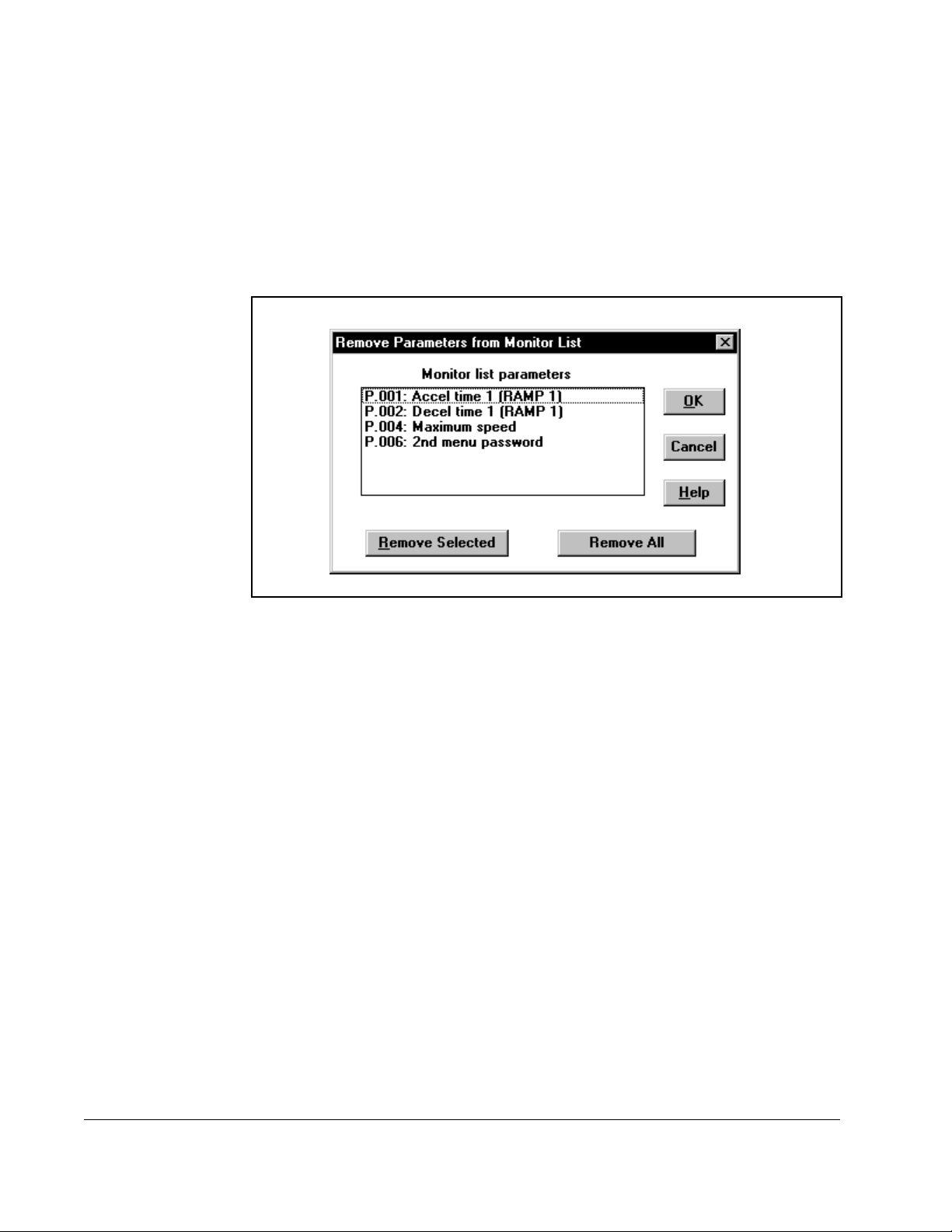
6.7 Clearing the Monitor List Display
Use the Clear button on the Parameter Monitor to remove selected parameters or all
parameters from the monitor list display. This command only clears the parameters
shown in the monitor list; it does not remove them from the saved monitor list files.
To remove only parameters you select, follow these steps:
Step 1. Select Clear to display the Remove Parameters from Monitor List dialog box.
Figure 6.5 – Remove Parameters from Monitor List Dialog Box
Step 2. Select the parameters you want to delete by using the mouse or the space
bar. Use the scroll bar, the arrow keys, and the page up and page down keys
to move through the list.
Step 3. Select Remove Selected to remove the parameters without exiting the dialog
box.
Step 4. If you want to remove more parameters, repeat this procedure. If you are
done removing parameters, select OK to return to the monitor list.
To remove all of the parameters, select Remove All. All of the parameters are removed
and you are returned to the monitor list.
6.8 Exiting the CS3000 Parameter Monitor
To exit the monitor list and return to the CS3000 main window, choose the Close
command from the CS3000 Parameter Monitor window. If a parameter list is displayed
in Parameter Monitor and it has not been saved to a file, you are prompted to save the
list. See section 6.5 for information about saving monitor list files.
6-8
Control and Configuration Software V6.1
Page 61

CHAPTER 7
Monitoring Drive Status and Alarms
This section describes how to monitor drive status indicators and alarms.
7.1 Displaying and Clearing the Fault Log and Alarm Log
You can display fault or alarm logs to help you troubleshoot problems.
To upload the fault log or alarm log from the drive, follow these steps:
Step 1. Make sure the personal computer is connected to the drive. Refer to chapters
2 and 3 for instructions about connecting the personal computer to a drive.
Step 2. From the Drive menu, choose Fault/alarm, or click .
The fault or alarm number, description, and time stamp is displayed in the list box. The
displayed log is updated about once a second with any new alarm or fault information.
Figure 7.1 shows a sample fault log while figure 7.2 shows a sample alarm log.
Monitoring Drive Status and Alarms
Figure 7.1 – Sample Fault Log List Box
7-1
Page 62

Figure 7.2 – Sample Alarm Log List Box
To switch between the fault and alarm list boxes, select the appropriate option for Log
Select. If the drive does not support an alarm log, the alarm log option is grayed and is
not selectable.
The time stamp displays the time when the fault or alarm occurred. This time is from
the drive memory. See the drive instruction manual for information about the time
stamp.
To change the time from a time stamp to a calculated time and date, select the
Calculate d time opt ion. The so ftwar e uses th e drive’s elapsed timer and the PC ’ s cloc k
to calculate the time that the fault occurred.
Important: The calculated time will be incorrect if the drive was powered down or if
the elapsed timer was reset since the fault occurred. This is because the
fault log information is saved if the drive’s power has been turned off.
7-2
Control and Configuration Software V6.1
Page 63

Table 6.1 describes how you can use the logs.
Table 7.1 – Using the Fault and Alarm Logs
To: Do the following:
print the displayed log Select Print.
The standard Windows Print dialog box is
displayed.
save the list of faults or alarms to a file
that can be viewed by an editor such
as Windows Notepad
Step 1. Select Print. The standard
Windows Print dialog box is
displayed.
Step 2. Select the Print to File checkbox.
Step 3. Se le ct OK .
The Print Fault [or Alarm] Log to
File dialog box is displayed. This
dialog box is the same as the
Save dialog box. Specify a
directory, file name, and
extension.
clear the fault or alarm log Select Clear.
The logged faults or alarms are deleted
from the log. This command clears only
the log that is currently displayed. Clear
does not reset drive faults or eliminate the
cause of the alarms; it simply clears the
log.
reset the drive after a fault Select Stop/Reset in the Drive Control
window.
A reset command will be sent to the drive.
This command will not be available if the
CS3000 software is not the control
source.
exit the log window Select Close.
Monitoring Drive Status and Alarms
7-3
Page 64
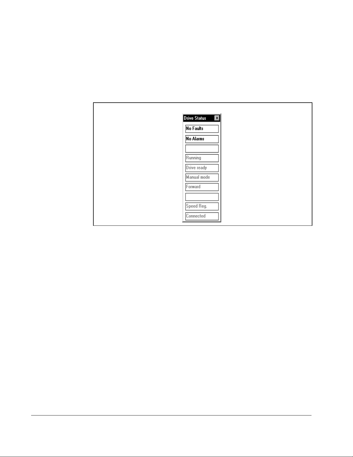
7.2 Monitoring Drive Status
The Drive Status window, shown in figure 7.3, automatically opens when you connect
to a drive.The other functions in the CS3000 software are still accessible while this
window is open. You can move this window, close it, or leave it displayed. If you close
this window while connected to the drive, it can be re-opened by using the Status
command from the Drive menu. If you disconnect from the drive, this window is
closed.
Figure 7.3 – Drive Status Window
7-4
Control and Configuration Software V6.1
Page 65

The indicat ors in the Drive Status window op erate as follows:
Table 7.2 – Drive Status Indicators
Indicator: Description:
Fault Highlighted when the drive is reporting that a fault exists.
Otherwise, the indicator is grayed and displays “No Faults.”
Alarm Highlighted when the drive is reporting an alarm.
Otherwise, the indicator is grayed and displays “No Alarms.”
Log Full Highlighted when the fault log is full. When this occurs, faults are
no longer added to the log.
Running/Jogging/Stopped Shows the appropriate text.
Drive ready/Drive not ready Shows the appropriate text.
Auto/Manual Displays the reference mode.
Forward/Rev erse Displays the drive direction if this information is available from the
drive.
Speed Reg/Torque Reg Displays the regulation type, if applicable.
Current Limit Highlighted when the drive is in current limit. The update rate is
about 1 second.
Connected/Disconnected Shows whether or not the CS3000 software is communicating with
a drive. If the software does not receive a response from the drive,
the status indicators are grayed and the Connected/Disconnected
indicator displays “Disconnected.”
7.3 Restoring Default Values to Drive Parameters
You can restore the default values to all of the drive parameters that have defaults. To
do this:
• From the Drive menu, choose Restore defaults.
If the drive does not support this command, this menu item is grayed and is not
selectable.
7.4 Saving Drive Parameter Values to Non-Volatile Memory on the Drive
You can save the values of the drive parameters in the drive’s runtime memory to nonvolatile memory on the drive. To do this:
• From the Drive menu, choose Memory save.
If the drive does not support this command, this menu item is grayed and is not
selectable.
Monitoring Drive Status and Alarms
7-5
Page 66

7.5 Restoring Drive Parameter Values from Non-Volatile Memory in the Drive
You can write the values stored by the Memory save command from non-volatile
memory on the drive into the drive’ s runtime memory. To do this:
• From the Drive menu, choose Memory restore.
If the selected drive does not support this command, then this menu item is not
selectable.
7-6
Control and Configuration Software V6.1
Page 67

This section describes how to control the drive using the CS3000 software.
8.1 Connecting a Drive
You must establish communication with the drive that is connected to the personal
computer. When the CS3000 software is successfully connected to the drive, all of the
CS3000 menu items supported for the drive are available. The CS3000 software
attempts to connect to the drive when the software first starts up. If you cannot
connect to the drive, see chapter 3.
To establish communication with the drive, follow these steps:
Step 1. From the Drive menu, choose Connect, or click .
Step 2. If you have a configuration file opened, the software prompts you to save that
configuration. Choose Yes or No.
If the CS3000 software does not support the drive, a message box prompts
you to continue. If you continue, some parameters in the drive may not be
supported by the CS3000 software. The software reports these parameters
in the Unknown Parameters dialog box. The unknown parameters can only
be used in the Parameter Monitor.
CHAPTER 8
Controlling the Drive
The CS3000 software connects to the drive and automatically:
• reads the drive type and version number from the drive
• makes sure it supports the drive
• uploads parameter information from the drive
The software is now communicating with the drive and can use all of the options in the
Drive menu.
8.2 Disconnecting a Drive
You can stop communication between the software and the drive by disconnecting the
drive. Except for Connect, Select, and Parameter Monitor, the commands in the Drive
menu are not available when the CS3000 software is not connected to the drive.
To stop communication with the drive:
Step 1. From the Drive menu, choose Disconnect or click on
Step 2. Select the drive version number you want to disconnect.
Step 3. Choose OK.
Controlling the Drive
8-1
Page 68
The main window shows “Disconnected.” The CS3000 software cannot communicate
with the drive until it is reconnected by using the Connect option or by restarting the
CS3000 software.
8.3 Controlling a Drive
ATTENTION:Only qualified electrical personnel familiar with the
construction and operation of the equipment and the hazards involved
!
Important: This function is available only for GV3000 drives version 5.0 (and later)
By using the Drive Control dialog box, you can control the Liqui-Flo drive, GV3000
drive (version 5.0 and later) or FlexPak 3000 drive (version 3.1 and later) by:
• selecting the control source, reference mode, and motor rotation directi on
• setting the drive reference
• starting and stopping the drive
• monitoring the drive ind icators
should adjust or operate this equipment. Failure to observe this
precaution could result in severe bodily injury or loss of life.
and FlexPak 3000 drives version 3.1 (and later). If you are using an earlier
version of these drives, the CS3000 software cannot be used to control
the drive.
To access the Drive Control dialog box, follow these steps:
Step 1. Make sure the personal computer is connected to the drive. Refer to section
7.1 for information about establishing communication with the drive.
Step 2. From the Drive menu, choose Control or click .
A danger message is displayed.
Step 3. Make sure you understand this message, then select OK to display the Drive
Control window. Figure 8.1 shows an example of a Drive Control window.
8-2
Control and Configuration Software V6.1
Page 69
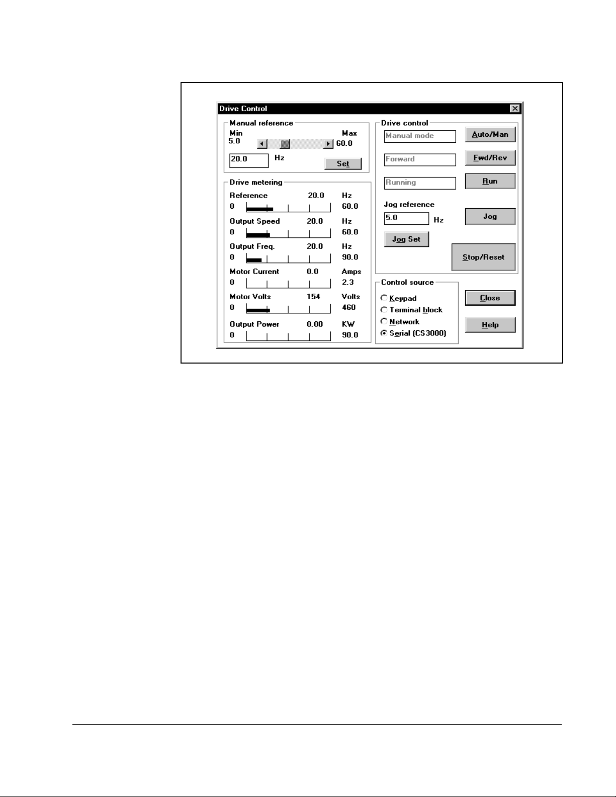
Figure 8.1 – Drive Control Window
You can also access other CS3000 software functions while the Drive Control window
is on the screen. The Drive Control window remains open until you close the window
(by selecting the Close button) or exit the CS3000 software.
The following sections describe how to use the Drive Control window to control a
drive’s functions.
Important: If a running drive that is being controlled by the CS3000 software loses
communication with the software, a serial fault occurs and the drive stops.
If the running drive is being controlled by its front-panel and
communication with the software is lost, the message “Disconnected”
appears in the main window, and the drive status window displays “Not
Connected.”
Controlling the Drive
8-3
Page 70

8.4 Selecting the Contr ol Source
The following note applies to GV3000 and Liqui-Flo AC drives only.
ATTENTION:When parameter P .055 is set to ON, the STOP/RESET key
is functional only from the selected control source. As a safety precaution,
!
You can select one of the following as the control source for the drive:
• Local
• Terminal Strip
•Serial
•Network
You must select Serial to control the drive by using the Drive Control window. If any
other control source is selected, you can only monitor the drive functions displayed in
the Drive Metering window and stop the drive by using Stop/Reset; all of the other
drive commands on the Drive Control screen are disabled.
Reliance Electric recommends that an emergency stop push button be
located near the drive in an easily accessible location. As a further safety
precaution, the user should post a warning on the drive to alert personnel
that the STOP/RESET key is not functional. Failure to observe this
precaution could result in severe bodily injury or loss of life.
8.5 Selecting the Reference Mode (Auto/Manual)
The Reference Mode control is active only if the control source is set to Serial
(CS3000 software control). Use the Auto/Man button to switch the drive reference
mode for the connected drive between auto mode and manual mode.
To use references from the: Choose:
Set Reference dialog box within the Drive Control
window
selected terminal strip source Auto mode
Manual mode
8.6 Selecting the Direction of Motor Rotation
The direction control is active only if the control source is set to Serial (CS3000
software control). The Fwd/Rev button toggles between Forward and Reverse. When
you make a selection, the appropriate command (forward or reverse) is sent to the
drive.
8.7 Setting the Drive Reference
The Manual Reference group box lets you set the drive reference.
8-4
Control and Configuration Software V6.1
Page 71
Set the drive reference by:
• moving the scroll bar to change the reference value and automatically send the
value to the drive, or
• entering a new value in the edit box and selecting the Set button to send the
reference value to the drive
8.8 Setting the Jog Referenc e
The Jog reference box lets you set the jog reference. The valid values are the same as
for the manual reference. To do this:
Step 1. Click in the Jog reference box and type a new value.
Step 2. Press the Jog Set button.
8.9 Starting and Stopping the Drive
The following note applies to GV3000 and Liqui-Flo AC drives only.
ATTENTION:When parameter P .055 is set to ON, the STOP/RESET key
is functional only from the selected control source. As a safety precaution,
!
Reliance Electric recommends that an emergency stop push button be
located near the drive in an easily accessible location. As a further safety
precaution, the user should post a warning on the drive to alert personnel
that the STOP/RESET key is not functional. Failure to observe this
precaution could result in severe bodily injury or loss of life.
Use the Run, Jog, and Stop/Reset buttons as follows:
To send this command to the drive: Press: Description:
start Run This control is disabled if the CS3000
software is not the control source.
jog
(Releasing the button sends the stop command.)
You can also jog the drive using the keyboard instead of a
mouse. To jog the drive using the keyboard:
Step 1. To move to the Jog button, press [Tab].
Step 2. To send the jog command to the drive, press the
space bar.
Step 3. To send the stop command to the drive, release
the spacebar.
stop
If the CS3000 software is the control source, a fault/alarm
reset is performed.
Jog (Note that buttons in Windows dialog
boxes normally cause an action when
the button is released). This control is
disabled if the CS3000 software is not
the control source.
Stop/
Reset
— FlexPak 3000 - This control is always
enabled, regardless of the control
source.
— GV3000 or Liqui-Flo - This control
can be disabled using parameter
P.055. See the software reference
manual for more information.
Controlling the Drive
8-5
Page 72
8.10 Monitoring Driv e Ind ic ato rs
The Drive Metering box displays six drive indicators for GV3000 or Liqui-Flo drives or
five drive indicators for FlexPak 3000 drives. The items displayed in the Drive Metering
box are dependent on drive type and regulation type.
For: The following indicators are listed:
GV3000 or Liqui-Flo drives configured
for vector regulation
GV3000 or Liqui-Flo drives configured
for volts/hertz regulation
FlexPak 3000 drives • Selected reference
• Selected reference
• Motor speed
• Motor current
• Motor voltage
• Motor torque
• Output power
• Selected reference
• Output speed
• Output frequency
• Motor voltage
• Motor current
• Output power
• Motor speed
• Armature volts
• Motor current
8-6
• Percent load
Each drive metering value is displayed as a visual thermometer-type indicator and as
a numeric value. If the numeric value exceeds the range of the indicator, the indicator
moves slightly beyond the far right line in the indicator grid. The units (RPM, Amps,
etc.) shown in figure 8.1 are examples only. The actual units are defined by the drive
type are preset.
Control and Configuration Software V6.1
Page 73

This section describes how to use the PC Scope.
9.1 About PC Scope
Use PC Scope to plot drive signals. PC Scope displays the plotted values as a trace.
The type of signals you can acquire depends upon the drive you have connected.
With PC Scope, you can:
• acquire traces of up to two signals at a time
• capture a trace and save it as a snapshot, which you can then compare to a newly
acquired trace
• define a trigger for the traces and specify how much data is gathered and
displayed before the trigger condition
• define a data sampling rate and the number of samples to capture for a given
trace
CHAPTER 9
Using PC Scope
• define a color for each to help you discern traces and trace snapshots
Figure 9.1 shows the PC Scope screen. The screen has its own toolbar and status
window. Table 9.1 explains the PC Scope toolbar buttons.
Using PC Scope
9-1
Page 74

Figure 9.1 – The PC Scope Screen
9-2
Control and Configuration Software V6.1
Page 75

Table 9.1 – PC Scope Toolbar Buttons
To: Use this button: Or this menu command:
Clears the trace setup,
File | New
display, and data.
Open a saved trace file. File | Open
Save the currently displayed
File | Save
trace data, set up, and the
snapshots as a trace or ASCII
file.
Open the Trace Signal Setup
Trace | Setup
dialog box.
Zoom the trace display to the
View | Zoom In
area bounded by the cursors.
Redisplay the trace in the
View | Zoom X1
normal view.
Using PC Scope
Turn cursors on or off. View | Cursors
Turn cursor tracking on or off. Cursor | Track
Access the online help. Help
9-3
Page 76
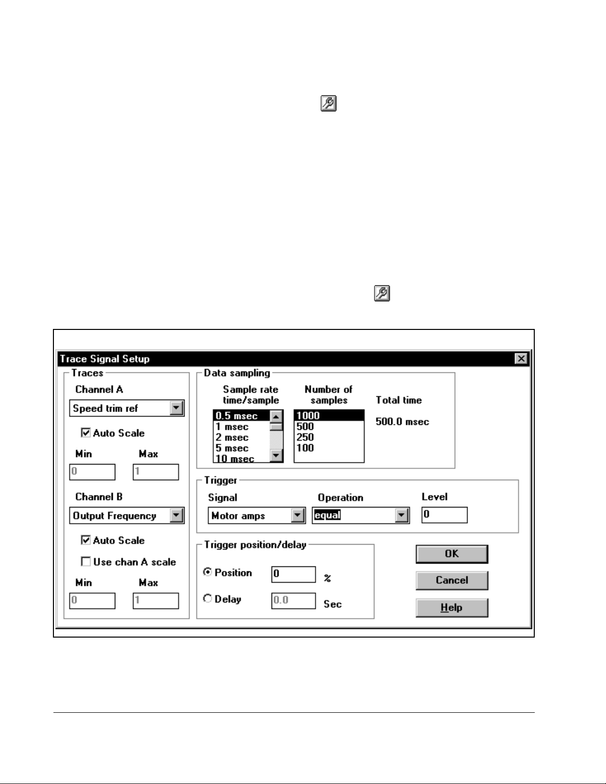
To begin using PC Scope, follow these steps:
Step 1. Set up the trace by clicking and defining the trace information. (See
section 9.2 for more information.)
Step 2. Choose how to acquire the trace data. (See section 9.3 for more information.)
9.2 Setting Up a Trace
Before you can acquire any trace data, you must set up the trace by:
• specifying the signals for the trace(s) (See section 9.2.1.)
• setting up data sampling (See section 9.2.2.)
• setting up the trigger (See section 9.2.3.)
Set up a trace by using the Trace Signal Setup dialog box. To access this dialog box:
• From the Trace menu, choose Setup or click .
Figure 9.2 shows the Trace Signal Setup dialog box.
9-4
Figure 9.2 – Trace Signal Setup Dialog Box
Control and Configuration Software V6.1
Page 77

9.2.1 Specifying Signals
Use the Traces group box in the Trace Signal Setup dialog box to specify the signal for
each trace.
To specify a signal, follow these steps:
Step 1. Select the drive signal whose values you want to plot as a trace. The
available signals are determined by the type of drive that is connected.
• Choose the signal or None to be used for Trace A by using the Channel A
list box.
• Choose the signal or None to be used for Trace B by using the Channel B
list box.
Step 2. Choose the type of scale you want to use for each trace.
To: Do the following:
Use rounded units per division
values based on the data in the
trace waveform
Specify actual trace vertical axis
minimum and maximum values
Use the scale for Trace A as the
scale for Trace B
9.2.2 Setting Up Data Sampling
Use the Data sampling group box in the Trace Setup dialog box to define how the
signal data is to be sampled. The settings apply to both traces. T o set up data
sampling, follow these steps:
Select the Auto Scale option for the trace you
are defining.
The difference between the minimum and
maximum values in the trace data is
determined from the waveform data, and the
values are rounded up to the next whole
value. For example, a value of 1.763 is
rounded to 2.
The minimum and maximum values are also
set to values beyond the actual values in the
trace waveform data.
Enter the vertical axis minimum and maximum
values in the Min and Max boxes for the trace
you are defining.
Select the option: Use chan A scale.
Using PC Scope
Step 1. Choose how often you want to acquire signal data by choosing a sampling
rate. Choose from 0.5 ms to 10 s.
Step 2. Choose the number of data samples in the trace. Choose a value from 1000
to 100.
Once you select the sample rate and number of samples, the amount of time
for the acquisition is displayed.
9-5
Page 78

9.2.3 Setting Up the Trigger
Use the Trigger and T rigger delay/position group boxes in the Trace Signal Setup
dialog box to define a trigger that will begin a data acquisition. You do not need to set
up a trigger if you plan to use Auto or Manual to acquire traces. See section 8.3 for
more information.
To set up trigger, follow these steps:
Step 1. Choose a drive signal you want to use as a trigger from the Signal list box.
Step 2. Choose the trigger operation (if desired) that causes the trigger condition by
using the Operation list box. The available trigger operations are determined
by the drive type. Some examples of trigger operations are: less than, greater
than, and equal to.
Step 3. Choose a trigger level that is to be used by the trigger operation. The units
and normalization depend upon the trigger signal.
Step 4. Choose a trigger position or delay by selecting the appropriate option and
entering a value.
To: Choose:
specify how many samples are displayed in the trace
before and after the trigger
For a trigger position of zero percent, the trigger is at
the beginning of the trace (all samples displayed were
acquired after the trigger). For a trigger position of
100%, the trigger is at the end of the trace, a position
of 50% is in the center, etc.
specify the amount of time between the trigger and the
beginning of data acquisition.
The delay is measured in seconds.
Position
Delay
9-6
Control and Configuration Software V6.1
Page 79

9.3 Acquiring a Trace
Once you set up a trace, you must define how the trace is to be acquired. A trace can
be acquired:
• continuously, regardless of a trigger condition
• continuously or once, as specified by a defined trigger
Use the Trace menu or the radio buttons in the toolbar to define how a trace is to be
acquired.
To:
From the Trace menu, choose this
option, or click on this radio button:
continuously acquire trace data by
sending a manual trigger
The trigger setup has no effect on the
trace acquisition.
acquire trace data by sending a
manual trigger to the drive
The trigger setup has no effect on the
trace acquisition.
continuously acquire trace data based
on the trigger setup
After the trace is uploaded and
displayed, the trace acquisition is reenabled, and the cycle starts over.
Trace data is acquired until you
change the trace acquisition
selection.
acquire a trace based on the trigger
setup
The trace data is acquired when the
trigger condition has been reached.
stop a trace acquisition in progress
If an acquisi tion is no t in prog ress , the
trace display is frozen as it is.
Auto
Manual
Normal
Single
Hold
Using PC Scope
Figure 9.3 illustrates an acquired trace.
9-7
Page 80
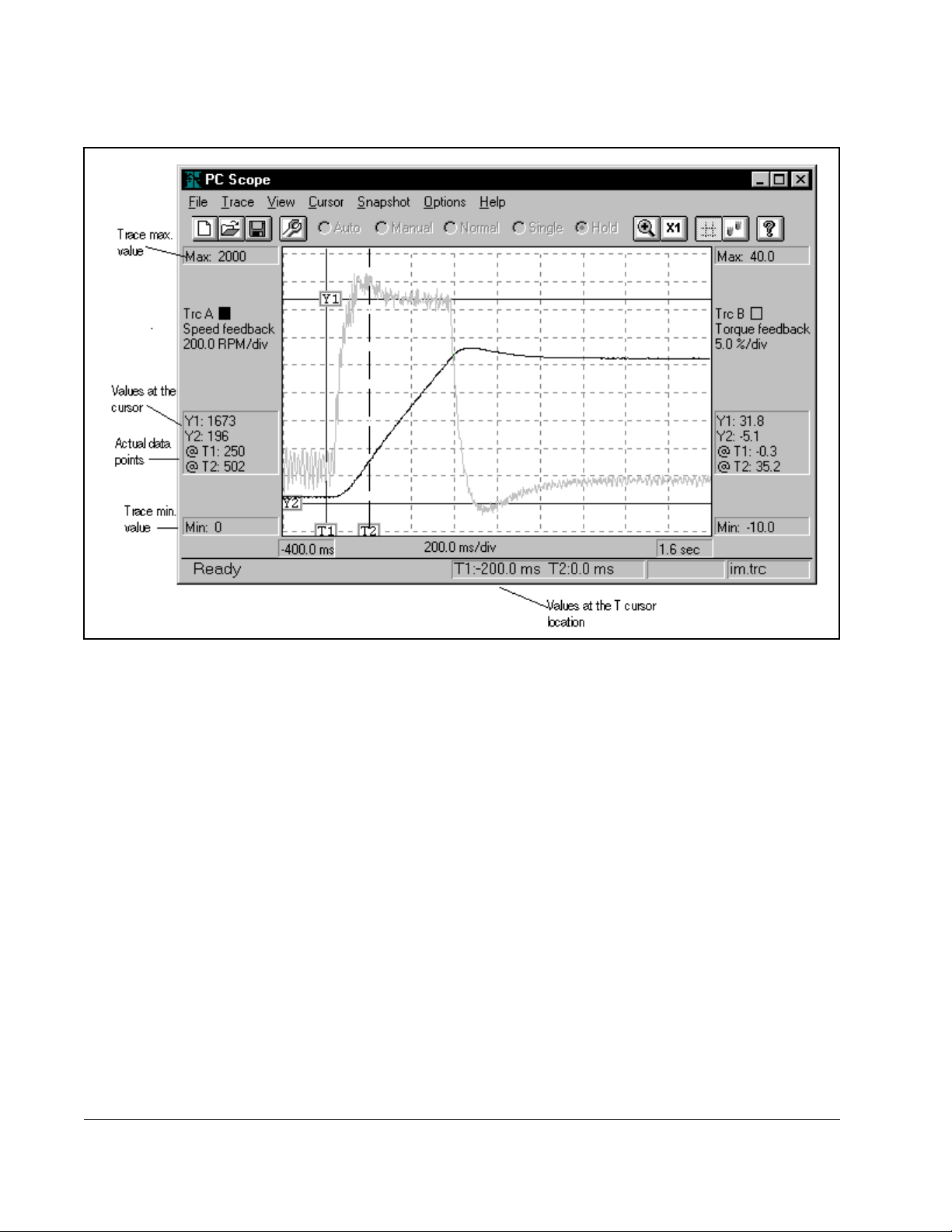
Figure 9.3 – Sample T r ace
9.4 Working with the Cursors
Cursors help you read the value at a specific point on a trace waveform to help you
tune and troubleshoot the drive. PC Scope has two cursor types:
• Y cursors are positioned on a vertical value on the display
• T cursors are positioned on a horizontal or time value
You can read actual data points where the waveform crosses the T cursors. These
values are labeled as@T1 and @T2. Because these are actual data points, you can
use them for calculations. The Y cursor values are based on the scale of the trace
display, so the value is determined by the display resolution and are not as accurate
as the actual data points displayed as the @T1 and @T2 values.
9-8
Control and Configuration Software V6.1
Page 81

9.4.1 Moving a Cursor
You can select a cursor by:
• clicking on the cursor label with the mouse
• using the Cursor menu
• using the [Tab] key
Move the cursors by:
• using the up, down, right, and left arrow keys or Shift + arrow key
• clicking on the label with the mouse and dragging the cursor
9.4.2 Specifying the Cursors To Track Each Other
You set the cursors to track together when you move them. This way the cursors can
move left and right and up and down while maintaining the same distance between T1
and T2 or Y1 and Y2.
To set the T and Y cursors so they track together:
• From the Cursor menu, choose Track or click .
Turning track off lets you move the T cursors independently from each other and the Y
cursors independently from each other. Cursor tracking can be turned on and off by
toggling the menu selection or toolbar button.
9.5 Changing Views
You can turn the cursors on and off and magnify the trace display as described in the
following sections.
9.5.1 Turning Cursors On and Off
You can choose to show or not the show the cursors on the trace display.
To turn cursors on or off:
• From the View menu, choose Cursors or click .
You cannot use the Zoom feature if the cursors are off.
Using PC Scope
9-9
Page 82

9.5.2 Magnifying the Trace Display
You can magnify the area of the trace display that is bounded by the cursors.
To magnify the display:
• From the View menu, choose Zoom In or click .
To return the display back to the normal view:
• From the View menu, choose Zoom X1 or click .
If you selected the Auto Scale option in the Trace Setup dialog box the PC Scope
scales ten vertical axis to even values. This may result in no change when you zoom
into the trace.
9.6 Taking a Trace Snapshot
You can compare one trace with another by saving trace data and displaying it as a
background for the next trace. This saved trace data is called a snapshot. You can
take a snapshot of either trace A or B or both. Also, you can choose a color to use for
displaying trace snapshots (see section 9.6.2).
9.6.1 Taking a Snapshot
To save a trace and have it displayed as the background for subsequent traces, do the
following:
From the Snapshot
To:
save the current Trace A as a
snapshot
save the current Trace B as a
snapshot
save both Trace A and Trace
B as snapshots
clear the snapshots Clear The snapshot traces are removed
menu, choose: Description:
Trace A This trace appears as the background
for the next Trace A.
Trace B This trace appears as the background
for the next Trace B.
Trace A & B The traces appear in the background
for the next traces.
from the background.
9-10
Control and Configuration Software V6.1
Page 83
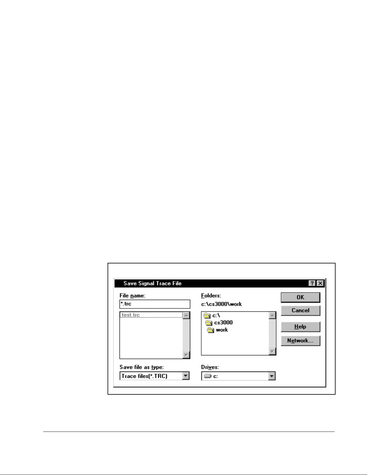
9.6.2 Choosing the Trace Snapshot Colors
You can choose the color that is used to display the snapshots of Trace A or Trace B.
Keep in mind that the trace display window is displayed using the Windows menu
background color, so be careful not to display trace snapshots in the same color, or
the trace will not show up.
To choose a color for a trace snapshot, follow these steps:
Step 1. From the Options menu, choose SnapA Color or SnapB Color.
The color selection dialog box is displayed.
Step 2. Select a standard color or create a custom color and click OK.
Traces can be displayed only in solid colors. If you choose a mixed color, the nearest
solid color is used.
9.7 Saving a Trace File
You can save a trace as either a trace file (.TRC) or an ASCII file (.TRA). Saving a
trace as an ASCII file lets you import the data into another program such as a
spreadsheet program.
Use the Save As command to save the file with a new name. To save a trace file,
follow these steps:
Step 1. From the File menu, choose Save or Save As.
The Save a Signal Trace File dialog box is displayed.
Figure 9.4 – Save a Signal Trace File Dialog Box
Using PC Scope
Step 2. In the file name field, type the name for the file.
9-11
Page 84
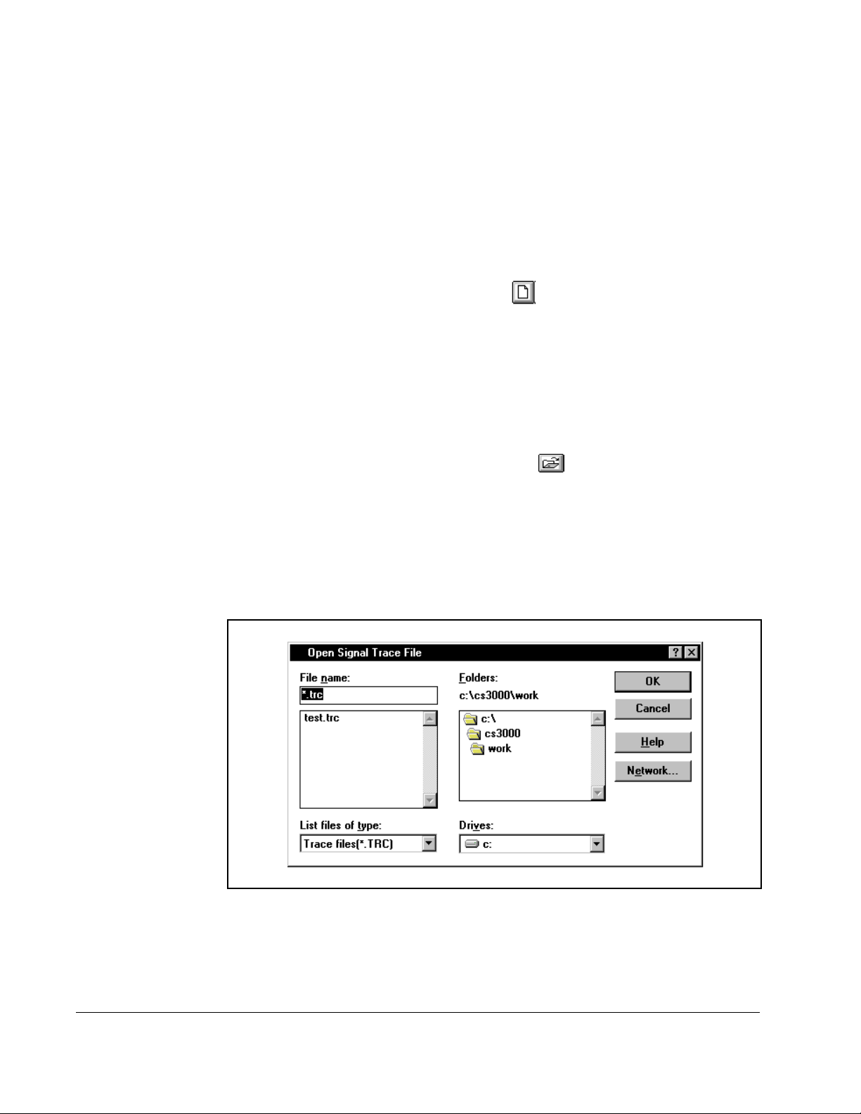
Step 3. From the Save file as type list box, choose whether you want to save the file
as a Trace file (.TRC) or as an ASCII file (.TRA).
Step 4. From the Drives list box, specify the location where you want to save the file.
Step 5. Click OK to save the file.
9.8 Clearing the Tr ace Display and Setup
You can clear the trace display and setup. To do this:
• From the File menu, choose New or click .
Creating a new trace file deletes any acquired trace data and clears the trace
display.
9.9 Opening a Trace File
You can open a previously saved trace file. To do this, follow these steps:
Step 1. From the File menu, select Open or click .
If you already have a configuration file open and made edits to it that have
not been saved, the software prompts you to save the changes. Make the
appropriate selection. See section 8.7 for more information about saving
configuration files.
The Open Signal Trace File dialog box is displayed. An example is shown in
figure 9. 5.
Figure 9.5 – Open Signal T race File Dialog Box
Step 2. The Open Signal Trace File dialog box defaults to the working directory of the
CS3000 software, which was specified during installation. If this is not the
correct directory, select the directory where the file is stored.
9-12
Control and Configuration Software V6.1
Page 85

Step 3. Select the name of the file you want to open by double-clicking on it with the
mouse. The name of the file should be copied in the File Name box. If not,
click on it again.
Step 4. Select OK to open the file. To close the dialog box without selecting a file,
select Cancel.
The trace file is opened.
9.10 Closing PC Scope
Close PC Scope by choosing Close from the File menu.
Using PC Scope
9-13
Page 86

9-14
Control and Configuration Software V6.1
Page 87

CHAPTER 10
Troubleshooting
This section describes basic troubleshooting information.
10.1 Using Error Messages
An error message might be displayed on the screen while you are using the CS3000
software. In most cases, you should be able to correct the error condition by following
the course of act ion describ ed b y t he er ror me ssag e . Ho w e ver , if th e err or me ssa ge is
preceded by an error number, in the format:
this indicates an error that might require assistance to correct. In this case, write down
the error and the error number, and contact Reliance Electric.
See Appendix A for a list of error messages and their causes.
10.2 Getting Assistance from Reliance Electric
If you have any questions or problems with the products described in this instruction
manual, contact your local Reliance Electric sales office.
Error <number> <description>
,
For technical assistance, call 1-800-726-8112.
Troubleshooting
10-1
Page 88

10-2
Control and Configuration Software V6.1
Page 89

APPENDIX A
Error Messages
General Error or Error <number> <description>
If you receive a numbered error, record the error number and any message that is
displayed, and call Reliance Electric for assistance.
Out of memory error. Close other applications to free memory.
This error is displayed if the software cannot allocate RAM. If it is displayed, you
should close other programs or add memory to the computer.
Out of Disk Space.
This error occurs if you attempt a print to file or save a configuration to a disk that has
insufficient space.
Missing or unreadable files. Reinstall CS3000.
At start-up or when a drive is selected, the CS3000 software reads information from
data files. This error is displayed if these files have been altered or are not located in
the directory containing the CS3000 software.
Error. Check printer.
An error occurred while trying to use the printer.
Error. Could not create timer. Close other applications to free a timer.
Windows has a limited number of timers. The CS3000 software requires a timer if it is
connected to a drive. This message is displayed if no timers are available.
File Open Error. Check Disk.
This error can occur if there is a disk problem.
File read error. Check disk.
This error can occur if the CS3000 software could not read a file.
File write error. Check disk.
This error can occur while writing to a file.
Cannot read file. File has been corrupted.
This message indicates that a configuration file has been altered and that the CRC
value stored in the file is no longer valid.
Drive data file format error. Reinstall CS3000.
This message indicates the drive data file format is incorrect or the file has one or
more unknown record types. This indicates that the CS3000 software is incorrectly
installed.
The configuration file drive type is different from the selected drive type.
This error occurs if you attempt to open a configuration file that was created for a drive
type that is not the currently selected drive type.
Error Messages
A-1
Page 90

The connected drive is not supported.
This error is displayed if the CS3000 software attempts to connect to a drive that
returns an unrecognized drive type.
Parameter(s) not relevant for the current control type found in the monitor list
have been ignored.
This message is displayed if a monitor list is recalled that was used for a different
control type than the one currently selected. Only parameters that are specific to the
currently selected control type are displayed.
The file was created for an unknown drive.
This error is displayed if you attempt to open a configuration file that was created for a
drive that is not recognized by the CS3000 software.
Communication error.
Can occur when the CS3000 software is communicating with the drive via the serial
communication connection. Check the cables, drive power, and the COM port
selection.
Parameter value is invalid.
Indicates a parameter value syntax error.
Parameter value has not been entered.
Indicates a missing parameter value.
Parameter value is out of range.
Indicates an out of range parameter value.
COMMUNICATION ERROR MESSAGES
Unknown response from the drive.
Displayed if the drive returns a response error code that is not recognized by the
CS3000 software.
Operation cannot be performed while drive is running.
The operation that was attempted cannot be done if the drive is running. You must
stop the drive to perform the operation.
Operation cannot be performed during download.
The operation that was attempted cannot be done if a download to the drive is in
progress.
ID format is invalid.
Version format is invalid.
These messages indicate that the response to a request to the drive for its type and
version is invalid.
A parameter VDR index was invalid.
If this error occurs, the CS3000 software attempted to read or write to a parameter
with an invalid index number. This could indicate that the memory in the computer has
been corrupted or that the CS3000 software itself is corrupted.
Download cannot be performed while the drive is running.
This message is displayed if a download is attempted when the drive is running. The
drive must be stopped before a configuration can be downloaded.
A-2
Control and Configuration Software V6.1
Page 91

Download cannot be opened. The drive is busy.
The drive is performing another operation. Wait a short amount of time and attempt
the operation again.
Download cannot be performed. A network card is the control source.
Change the control source from the drive keypad to perform a download.
Variable processing errors occurred in the drive.
The drive had to change parameter values after a download was completed.
Parameter write errors occurred during download.
Some parameter values could not be written to the drive. This error indicates a
problem in the CS3000 software or drive.
Parameter write attempted to a configurable parameter while drive is running.
Configurable parameters cannot be changed while the drive is running. The drive
must be stopped to perform the intended operation.
Parameter value is out of range.
A parameter write was attempted with an out of range value.
Parameter could not be found in the drive.
The CS3000 software attempted to read the value of a parameter that is not in the
drive.
The number of parameters in read is invalid.
The read request to the drive was invalid.
Read attempted with invalid parameter index.
The CS3000 software attempted to read a parameter that does not exist in the drive.
Invalid read message format.
The read message format created by the CS3000 software is invalid.
COM port is not available.
The selected COM port is not installed in the PC or is being used by a DOS
application, such as the mouse driver.
COM port is being used by another application.
The selected COM port is being used by another Windows application.
Unable to read signal trace information from drive.
The CS3000 software could not read the information from the drive needed for the PC
Scope. Check the drive connection.
Sample rate not supported.
Under some conditions in a drive, a sample rate may not be available for a PC Scope
signal. Change the sample rate.
Failed to create status bar.
This error may be caused by a lack of memory. Close the application and retry.
Could not create toolbar.
This error may be caused by a lack of memory. Close the application and retry.
Error Messages
A-3
Page 92

A-4
Control and Configuration Software V6.1
Page 93

APPENDIX B
New Features in Version 6.1
Tuning for Vector-Controlled AC Drives
Chapter 5 describes how to tune vector-regulated GV3000 and Liqui-Flo drives.
PC Scope Improvements
• Grids can be turned on and off from the View menu.
• The T cursors and Y cursors can be turned on and off separately from the View
menu or from the tool bar buttons.
toggles the Y cursors on and off.
toggles the T cursors on and off.
New Features in Version 6.1
B-1
Page 94

B-2
Control and Configuration Software V6.1
Page 95

INDEX
A
About the Control and Configuration Software, 1-1
cables, 1-1
exiting the software, 2-10
hardware requirements, 1-2
intended audience, 1-3
menus, 2-7
overview, 1-1
purpose of this manual, 1-3
safety information, 1-3
software requirements, 1-1
starting the software, 2-5 to 2-7
terms used in this manual, 1-4
toolbars, 2-8 to 2-10
where to find additional information, 1-4
Additional information, 1-4
Audience, 1-3
Auto Scale, 9-5
ASCII, 9-11
C
Cables, 1-2
Communication, set up
connecting the serial port, 2-3 to 2-5
selecting the communication port, 2-5
selecting the drive, 2-5
Configuring the Drive, 3-1
comparing the drive configuration to the
opened configuration, 4-5
comparing the parameter values in the opened
configuration with those in another con-
figuration file, 4-4 to 4-5
creating a new configuration, 3-2
downloading a drive configuration, 4-2
editing a configuration, 3-7 to 3-10
assigning parameter values, 3-7 to 3-9
ending an editing session, 3-9
entering and editing a configuration de-
scripti on, 3-9 to 3-10
icons, 2-9
opening a drive configuration file, 3-3 to 3-4
different version of same drive, 3-5 to 3-6
printing a configuration, 3-12
saving a drive configuration, 3-12
saving the open drive configuration to another
file, 3-11
selecting a drive, 3-1
uploading a drive configuration, 4-1
Controlling the Drive
connecting a drive, 8-1
controlling a drive, 8-2 to 8-3
disconnecting a drive, 8-1
icons, 2-10
monitoring drive indicators, 8-6
selecting the,
control source, 8-4
direction of motor rotation, 8-4
reference mode, 8-4
setting the,
drive reference, 8-4
jog reference, 8-5
starting and stopping the drive, 8-5
Cursors, 9-8
D
Description
configuration, 3-9
Drive Parameters
adding to monitor list, 6-3
assigning values, 6-4 to 6-6
clearing monitor display, 6-8
displaying a monitor list, 6-7
exiting the monitor, 6-8
overview, 6-1 to 6-2
removing from monitor list, 6-3
saving a monitor list, 6-6
E
Editing
a configuration, 3-7 to 3-10
assigning parameter values, 3-7 to 3-9
configuration description, 3-9 to 3-10
ending an editing session, 3-9
drive parameters, 6-4 to 6-6
assigning values, 6-4 to 6-6
clearing monitor, 6-8
removing, 6-3
Index
Index-1
Page 96

trace file,
acquiring, 9-7
clearing the trace display and setup, 9-12
changing views, 9-9
opening a trace file, 9-12
saving a trace file, 9-11
Error messages, 10-1
F
FlexPak 3000, 1-1, 1-3, 1-4, 4-2, 6-1, 8-2
G
GV3000, 1-1 to 1-4, 3-1, 3-3, 3-9, 6-5, 8-2, 8-6
tuning, 5-1 to 5-10
Getting assistance from Reliance Electric, 10-1
I
Installation
before installing, 2-1
completing, 2-2 to 2-3
setting up communication, 2-3 to 2-5
Windows 3.1, 2-2
Windows 95, 2-2
J
Jog, 7-5, 8-5
Jog reference, 8-5
P
Parameter Values
adding, 6-3
comparing, 4-3 to 4-5
PC Scope
acquiring a trace, 9-7 to 9-9
clearing the trace display and setup, 9-12
closing the PC Scope, 9-13
changing views, 9-9
icon, 2-10
magnifying the trace display, 9-10
opening a trace file, 9-12
overview, 9-1 to 9-4
saving a trace file, 9-11
setting up a trace, 9-4 to 9-6
specifying signals, 9-5
setting up data sampling, 9-5
setting up the trigger, 9-6
taking a trace snapshot, 9-10
taking a snapshot, 9-10
choosing the trace snapshot colors, 9-10
turning cursors on and off, 9-9
working with cursors, 9-8 to 9-9
moving a cursor, 9-8 to 9-9
specifying the cursors to track each other,
9-9
Printing
drive configuration, 3-12
R
L
Liqui-Flo, 1-1 to 1-4, 3-1, 3-3, 3-9, 6-5, 8-2, 8-6
tuning, 5-1 to 5-10
M
Monitoring Drive Status and Alarms
displaying and clearing the fault log and alarm
log, 7-1 t o 7-3
drive status, 7-4 to 7-5
Menus, 2-7
N
Non-voliatile memory, 7-5
Index-2
restoring,
default values to drive parameters, 7-5
drive parameter values from non-volatile mem-
ory on the drive, 7-6
Requirements
hardware, 1-2
software, 1-1
RS-232, 1-3, 2-3 to 2-5
S
Safety, 1-3
Saving
drive configuration, 3-10 to 3-11
drive parameters, 7-5
icon, 2-9
monitor list, 6-5
Control and Configuration Software V6.1
Page 97

to another file, 3-11
trace file, 9-11
Setup
communication, 2-3 to 2-5
drive reference, 8-4
jog reference, 8-5
trace, 9-3, 9-4
windows, 2-2
snapshot, 9-10
start, 8-5
stop, 7-3, 8-5
T
Terms used in this manual, 1-4
Toolbars, 2-8 to 2-10, 9-3
Trace files
acquiring, 9-7
clearing the display and setup, 9-12
magnifying, 9-10
opening, 9-12
saving, 9-11
setting up, 9-4 to 9-6
specifying signals, 9-5
setting up data sampling, 9-5
setting up the trigger, 9-6
taking a snapshot, 9-10
taking a snapshot, 9-10
choosing the trace snapshot colors, 9-11
Trigger, 9-6
Troubleshooting
getting assistance from Reliance Electric, 10-1
using error messages 10-1
Tuning GV3000 and Liqui-Flo Drives
standard, 5-2 to 5-4
custom, 5-5 to 5-10
Z
Zoom, 9-3, 9-9
Index
Index-3
Page 98

Index-4
Control and Configuration Software V6.1
Page 99

Page 100

www.rockwellautomation.com
Corporate Headquarters
Rockwell Automation, 777 East Wisconsin Avenue, Suite 1400, Milwaukee, WI, 53202-5302 USA, Tel: (1) 414.212.5200, Fax: (1) 414.212.5201
Headquarters for Reliance Electric Products
Americas: Rockwell Automation, 6040 Ponders Court, Greenville, SC 29615-4617 USA, Tel: (1) 864.297.4800, Fax: (1) 864.281.2433
Europe/Middle East/Africa: Rockwell Automation, Brühlstraße 22, D-74834 Elztal-Dallau, Germany, Tel: (49) 6261 9410, Fax: (49) 6261 17741
Asia Pacific: Rockwell Automation, 55 Newton Road, #11-01/02 Revenue House, Singapore 307987, Tel: (65) 6356-9077, Fax: (65) 6356-9011
Publication CS3000-UM003D-EN -October 2003 © 2003 Copyright Rockwell International Corporation
 Loading...