

Page 1

ControlLogix 5580 Redundant
Controller
For Use in High Availability Systems
User Manual
Original Instructions
Page 2
ControlLogix 5580 Redundant Controller User Manual
Important User Information
Read this document and the documents listed in the additional resources section about installation, configuration, and
operation of this equipment before you install, configure, operate, or maintain this product. Users are required to familiarize
themselves with installation and wiring instructions in addition to requirements of all applicable codes, laws, and standards.
Activities including installation, adjustments, putting into service, use, assembly, disassembly, and maintenance are required to
be carried out by suitably trained personnel in accordance with applicable code of practice.
If this equipment is used in a manner not specified by the manufacturer, the protection provided by the equipment may be
impaired.
In no event will Rockwell Automation, Inc. be responsible or liable for indirect or consequential damages resulting from the use
or application of this equipment.
The examples and diagrams in this manual are included solely for illustrative purposes. Because of the many variables and
requirements associated with any particular installation, Rockwell Automation, Inc. cannot assume responsibility or liability for
actual use based on the examples and diagrams.
No patent liability is assumed by Rockwell Automation, Inc. with respect to use of information, circuits, equipment, or software
described in this manual.
Reproduction of the contents of this manual, in whole or in part, without written permission of Rockwell Automation, Inc., is
prohibited.
Throughout this manual, when necessary, we use notes to make you aware of safety considerations.
WARNING: Identifies information about practices or circumstances that can cause an explosion in a hazardous environment, which may
lead to personal injury or death, property damage, or economic loss.
ATTENTION: Identifies information about practices or circumstances that can lead to personal injury or death, property damage, or
economic loss. Attentions help you identify a hazard, avoid a hazard, and recognize the consequence.
IMPORTANT
Identifies information that is critical for successful application and understanding of the product.
Labels may also be on or inside the equipment to provide specific precautions.
SHOCK HAZARD: Labels may be on or inside the equipment, for example, a drive or motor, to alert people that dangerous voltage may
be present.
BURN HAZARD: Labels may be on or inside the equipment, for example, a drive or motor, to alert people that surfaces may reach
dangerous temperatures.
ARC FLASH HAZARD: Labels may be on or inside the equipment, for example, a motor control center, to alert people to potential Arc
Flash. Arc Flash will cause severe injury or death. Wear proper Personal Protective Equipment (PPE). Follow ALL Regulatory requirements
for safe work practices and for Personal Protective Equipment (PPE).
2 Rockwell Automation Publication 1756-UM015B-EN-P - February 2021
Page 3

Table of Contents
Preface . . . . . . . . . . . . . . . . . . . . . . . . . . . . . . . . . . . . . . . . . . . . . . . . . . . . . . . 9
Catalog Numbers . . . . . . . . . . . . . . . . . . . . . . . . . . . . . . . . . . . . . . . . . . . . . . . . 9
Overview . . . . . . . . . . . . . . . . . . . . . . . . . . . . . . . . . . . . . . . . . . . . . . . . . . . . . . . . 9
Additional Resources . . . . . . . . . . . . . . . . . . . . . . . . . . . . . . . . . . . . . . . . . . . . . 9
Chapter 1
ControlLogix 5580 High
Availability Systems
Configure the Redundancy
System
Features of the ControlLogix 5580 High Availability System . . . . . . . . . 12
Controller Keyswitch . . . . . . . . . . . . . . . . . . . . . . . . . . . . . . . . . . . . . . . . . . . . 13
Redundancy System Components . . . . . . . . . . . . . . . . . . . . . . . . . . . . . . . . 14
I/O Modules in Redundancy Systems . . . . . . . . . . . . . . . . . . . . . . . . . . 14
Fiber-optic Cable. . . . . . . . . . . . . . . . . . . . . . . . . . . . . . . . . . . . . . . . . . . . . . . . 15
Use Dual Fiber Ports with the 1756-RM2 Redundancy Module . . . . 15
Redundancy System Operations. . . . . . . . . . . . . . . . . . . . . . . . . . . . . . . . . . 17
System Qualification and Synchronization. . . . . . . . . . . . . . . . . . . . . 17
Switchovers . . . . . . . . . . . . . . . . . . . . . . . . . . . . . . . . . . . . . . . . . . . . . . . . . 18
Restrictions . . . . . . . . . . . . . . . . . . . . . . . . . . . . . . . . . . . . . . . . . . . . . . . . . . . . 19
Chapter 2
Before You Begin . . . . . . . . . . . . . . . . . . . . . . . . . . . . . . . . . . . . . . . . . . . . . . . 21
Download the Redundancy Firmware Bundle. . . . . . . . . . . . . . . . . . . . . . 22
Install the Firmware Bundle. . . . . . . . . . . . . . . . . . . . . . . . . . . . . . . . . . . . . . 22
Install the Redundancy Module Configuration Tool . . . . . . . . . . . . . . . . 22
Install the Redundancy System . . . . . . . . . . . . . . . . . . . . . . . . . . . . . . . . . . . 23
Configure Redundant Firmware. . . . . . . . . . . . . . . . . . . . . . . . . . . . . . . . . . 24
Upgrade the Firmware in the First Chassis . . . . . . . . . . . . . . . . . . . . . 24
Upgrade the Firmware in the Second Chassis . . . . . . . . . . . . . . . . . . 25
Set the initial Primary and Secondary Chassis . . . . . . . . . . . . . . . . . . . . . 25
After Designation. . . . . . . . . . . . . . . . . . . . . . . . . . . . . . . . . . . . . . . . . . . . 26
Conversion from a Non-redundant to a Redundant System. . . . . . 26
Qualification Status Via the RMCT . . . . . . . . . . . . . . . . . . . . . . . . . . . . 27
Reset the Redundancy Module . . . . . . . . . . . . . . . . . . . . . . . . . . . . . . . . 27
Remove or Replace the Redundancy Module . . . . . . . . . . . . . . . . . . . 28
Configure the EtherNet/IP
Network
Chapter 3
Requested Packet Interval (RPI) . . . . . . . . . . . . . . . . . . . . . . . . . . . . . . . . . . 29
IP Address Swapping . . . . . . . . . . . . . . . . . . . . . . . . . . . . . . . . . . . . . . . . . . . . 29
Static Versus Dynamic IP Addresses. . . . . . . . . . . . . . . . . . . . . . . . . . . 32
Reset the IP Address for an EtherNet/IP Communication Module 32
CIP Sync . . . . . . . . . . . . . . . . . . . . . . . . . . . . . . . . . . . . . . . . . . . . . . . . . . . . . . . 33
Produce/Consume Connections . . . . . . . . . . . . . . . . . . . . . . . . . . . . . . . . . . 35
Rockwell Automation Publication 1756-UM015B-EN-P - February 2021 3
Page 4

Table of Contents
Configure EtherNet/IP Communication Modules in a Redundant
System. . . . . . . . . . . . . . . . . . . . . . . . . . . . . . . . . . . . . . . . . . . . . . . . . . . . . . . . . 37
Before You Begin . . . . . . . . . . . . . . . . . . . . . . . . . . . . . . . . . . . . . . . . . . . . 37
Options for Setting the IP Addresses of EtherNet/IP
Communication Modules . . . . . . . . . . . . . . . . . . . . . . . . . . . . . . . . . . . . 37
Half/Full Duplex Settings. . . . . . . . . . . . . . . . . . . . . . . . . . . . . . . . . . . . . 37
Use a Redundancy System with Device Level Ring. . . . . . . . . . . . . . . . . . 38
Use a Redundancy System with Parallel Redundancy Protocol. . . . . . . 38
Chapter 4
Configure the Redundancy
Modules
Configure the Redundant
Controller
Determine If Further Configuration Is Required . . . . . . . . . . . . . . . . . . . 40
Configure the Redundancy Module . . . . . . . . . . . . . . . . . . . . . . . . . . . . . . . 41
Identify the RMCT Version . . . . . . . . . . . . . . . . . . . . . . . . . . . . . . . . . . . 42
Module Info Tab . . . . . . . . . . . . . . . . . . . . . . . . . . . . . . . . . . . . . . . . . . . . . . . . 43
Configuration Tab . . . . . . . . . . . . . . . . . . . . . . . . . . . . . . . . . . . . . . . . . . . . . . 45
Auto-synchronization . . . . . . . . . . . . . . . . . . . . . . . . . . . . . . . . . . . . . . . . 45
Chassis ID . . . . . . . . . . . . . . . . . . . . . . . . . . . . . . . . . . . . . . . . . . . . . . . . . . 46
Enable User Program Control. . . . . . . . . . . . . . . . . . . . . . . . . . . . . . . . . 46
Redundancy Module Date and Time . . . . . . . . . . . . . . . . . . . . . . . . . . . 46
Synchronization Tab . . . . . . . . . . . . . . . . . . . . . . . . . . . . . . . . . . . . . . . . . . . . 47
Commands in the Synchronization Tab. . . . . . . . . . . . . . . . . . . . . . . . 48
Recent Synchronization Attempts Log . . . . . . . . . . . . . . . . . . . . . . . . . 48
Synchronization Status Tab . . . . . . . . . . . . . . . . . . . . . . . . . . . . . . . . . . . . . . 50
System Update Tab. . . . . . . . . . . . . . . . . . . . . . . . . . . . . . . . . . . . . . . . . . . . . . 51
System Update Commands . . . . . . . . . . . . . . . . . . . . . . . . . . . . . . . . . . . 52
System Update Lock Attempts . . . . . . . . . . . . . . . . . . . . . . . . . . . . . . . . 54
Locked Switchover Attempts. . . . . . . . . . . . . . . . . . . . . . . . . . . . . . . . . . 55
Chapter 5
Configure the Redundant Controller. . . . . . . . . . . . . . . . . . . . . . . . . . . . . . 57
Enable Time Synchronization . . . . . . . . . . . . . . . . . . . . . . . . . . . . . . . . . . . . 59
Crossloads, Synchronization, and Switchovers. . . . . . . . . . . . . . . . . . . . . 61
Changing Crossload and Synchronization Settings . . . . . . . . . . . . . 61
Default Crossload and Synchronization Settings . . . . . . . . . . . . . . . 62
Recommended Task Types . . . . . . . . . . . . . . . . . . . . . . . . . . . . . . . . . . . 62
Continuous Task After Switchover . . . . . . . . . . . . . . . . . . . . . . . . . . . . 62
Multiple Periodic Tasks . . . . . . . . . . . . . . . . . . . . . . . . . . . . . . . . . . . . . . 63
Crossloads and Scan Time . . . . . . . . . . . . . . . . . . . . . . . . . . . . . . . . . . . . . . . 65
Estimate the Crossload Time . . . . . . . . . . . . . . . . . . . . . . . . . . . . . . . . . 65
Redundancy Object Attributes for Crossload Times . . . . . . . . . . . . . 66
Equation for Estimating Crossload Times. . . . . . . . . . . . . . . . . . . . . . 67
Set the Task Watchdog . . . . . . . . . . . . . . . . . . . . . . . . . . . . . . . . . . . . . . . . . . 67
Minimum Value for the Watchdog Time . . . . . . . . . . . . . . . . . . . . . . . 69
4 Rockwell Automation Publication 1756-UM015B-EN-P - February 2021
Page 5

Table of Contents
Chapter 6
Programming Best Practices Program to Minimize Scan Times . . . . . . . . . . . . . . . . . . . . . . . . . . . . . . . . 71
Minimize the Number of Programs . . . . . . . . . . . . . . . . . . . . . . . . . . . 72
Manage Tags for Efficient Crossloads . . . . . . . . . . . . . . . . . . . . . . . . . 73
Use Concise Programming . . . . . . . . . . . . . . . . . . . . . . . . . . . . . . . . . . . 75
Program to Maintain Data Integrity . . . . . . . . . . . . . . . . . . . . . . . . . . . . . . 76
Timer Instructions . . . . . . . . . . . . . . . . . . . . . . . . . . . . . . . . . . . . . . . . . . 76
Array (File)/Shift Instructions . . . . . . . . . . . . . . . . . . . . . . . . . . . . . . . . 77
Scan-dependent Logic . . . . . . . . . . . . . . . . . . . . . . . . . . . . . . . . . . . . . . . 78
Optimize Tasks . . . . . . . . . . . . . . . . . . . . . . . . . . . . . . . . . . . . . . . . . . . . . . . . . 80
Programming Considerations. . . . . . . . . . . . . . . . . . . . . . . . . . . . . . . . . . . . 81
Data Transfer . . . . . . . . . . . . . . . . . . . . . . . . . . . . . . . . . . . . . . . . . . . . . . . 81
SSV Instruction Operation . . . . . . . . . . . . . . . . . . . . . . . . . . . . . . . . . . . 81
Communications Performance . . . . . . . . . . . . . . . . . . . . . . . . . . . . . . . 81
Programed-scoped Tags. . . . . . . . . . . . . . . . . . . . . . . . . . . . . . . . . . . . . . 82
Redundant System Update (RSU) Operation . . . . . . . . . . . . . . . . . . . 82
Instruction Operation. . . . . . . . . . . . . . . . . . . . . . . . . . . . . . . . . . . . . . . . 82
Alarms. . . . . . . . . . . . . . . . . . . . . . . . . . . . . . . . . . . . . . . . . . . . . . . . . . . . . . 83
Diagnostics . . . . . . . . . . . . . . . . . . . . . . . . . . . . . . . . . . . . . . . . . . . . . . . . . 83
Conduct a Test Switchover . . . . . . . . . . . . . . . . . . . . . . . . . . . . . . . . . . . . . . . 84
Synchronization After a Switchover . . . . . . . . . . . . . . . . . . . . . . . . . . . 85
Program Logic to Run After a Switchover. . . . . . . . . . . . . . . . . . . . . . . . . . 86
Use Messages for Redundancy Commands . . . . . . . . . . . . . . . . . . . . . . . . 87
Verify User Program Control . . . . . . . . . . . . . . . . . . . . . . . . . . . . . . . . . 87
Use an Unconnected Message. . . . . . . . . . . . . . . . . . . . . . . . . . . . . . . . . 87
Configure the MSG Instruction . . . . . . . . . . . . . . . . . . . . . . . . . . . . . . . 88
Download the Project. . . . . . . . . . . . . . . . . . . . . . . . . . . . . . . . . . . . . . . . . . . . 90
Store a Redundancy Project to Nonvolatile Memory . . . . . . . . . . . . . . . . 91
Store a Project While the Controller is in Program or Remote
Program Mode . . . . . . . . . . . . . . . . . . . . . . . . . . . . . . . . . . . . . . . . . . . . . . 91
Store a Project While a System is Running . . . . . . . . . . . . . . . . . . . . . 92
Load a Project . . . . . . . . . . . . . . . . . . . . . . . . . . . . . . . . . . . . . . . . . . . . . . . 93
Online Edits . . . . . . . . . . . . . . . . . . . . . . . . . . . . . . . . . . . . . . . . . . . . . . . . . . . . 94
Partial Import Online (PIO). . . . . . . . . . . . . . . . . . . . . . . . . . . . . . . . . . . 94
Plan for Test Edits . . . . . . . . . . . . . . . . . . . . . . . . . . . . . . . . . . . . . . . . . . . 95
Assemble Edits with Caution . . . . . . . . . . . . . . . . . . . . . . . . . . . . . . . . . 96
Monitor and Maintain a
Redundancy System
Chapter 7
Controller Logging . . . . . . . . . . . . . . . . . . . . . . . . . . . . . . . . . . . . . . . . . . . . . . 99
Controller Log. . . . . . . . . . . . . . . . . . . . . . . . . . . . . . . . . . . . . . . . . . . . . . . 99
Controller Logging in Redundancy Systems . . . . . . . . . . . . . . . . . . . 100
Component Change Detection . . . . . . . . . . . . . . . . . . . . . . . . . . . . . . . 100
Monitor System Status . . . . . . . . . . . . . . . . . . . . . . . . . . . . . . . . . . . . . . . . . 100
Verify Date and Time Settings. . . . . . . . . . . . . . . . . . . . . . . . . . . . . . . . . . . 102
Verify System Qualification . . . . . . . . . . . . . . . . . . . . . . . . . . . . . . . . . . . . . 103
Check Qualification Status Via Module Status Displays . . . . . . . . 103
Check Qualification Status Via the RMCT . . . . . . . . . . . . . . . . . . . . . 105
Rockwell Automation Publication 1756-UM015B-EN-P - February 2021 5
Page 6

Table of Contents
Troubleshoot a Redundant
System
Check the EtherNet/IP Module Status. . . . . . . . . . . . . . . . . . . . . . . . . . . . 106
CPU Usage. . . . . . . . . . . . . . . . . . . . . . . . . . . . . . . . . . . . . . . . . . . . . . . . . 106
Connections Used . . . . . . . . . . . . . . . . . . . . . . . . . . . . . . . . . . . . . . . . . . 106
Chapter 8
General Troubleshooting Steps . . . . . . . . . . . . . . . . . . . . . . . . . . . . . . . . . . 107
Check the Module Status Indicators . . . . . . . . . . . . . . . . . . . . . . . . . . . . . 108
Use Programming Software to View Errors. . . . . . . . . . . . . . . . . . . . . . . 109
Redundant Controller Major Fault Codes . . . . . . . . . . . . . . . . . . . . . . 111
Use the RMCT for Synchronization Attempts and Status. . . . . . . . . . . . 111
Recent Synchronization Attempts. . . . . . . . . . . . . . . . . . . . . . . . . . . . . 111
Module-level Synchronization Status . . . . . . . . . . . . . . . . . . . . . . . . . 112
Use the RMCT Event Log . . . . . . . . . . . . . . . . . . . . . . . . . . . . . . . . . . . . . . . 113
Controller Events . . . . . . . . . . . . . . . . . . . . . . . . . . . . . . . . . . . . . . . . . . . 114
Event Classifications. . . . . . . . . . . . . . . . . . . . . . . . . . . . . . . . . . . . . . . . 115
Access Extended Information about an Event . . . . . . . . . . . . . . . . . 116
Interpret Extended Information for an Event . . . . . . . . . . . . . . . . . 117
Interpret Event Log Information. . . . . . . . . . . . . . . . . . . . . . . . . . . . . 118
Export Event Log Data . . . . . . . . . . . . . . . . . . . . . . . . . . . . . . . . . . . . . . 122
Export Diagnostics . . . . . . . . . . . . . . . . . . . . . . . . . . . . . . . . . . . . . . . . . 126
Contact Rockwell Automation Technical Support . . . . . . . . . . . . . . 127
Clear a Fault . . . . . . . . . . . . . . . . . . . . . . . . . . . . . . . . . . . . . . . . . . . . . . . 128
System Event History . . . . . . . . . . . . . . . . . . . . . . . . . . . . . . . . . . . . . . . . . . 129
System Event History Column Descriptions. . . . . . . . . . . . . . . . . . . 129
Edit a User Comment for a System Event . . . . . . . . . . . . . . . . . . . . . 130
Save System Event History . . . . . . . . . . . . . . . . . . . . . . . . . . . . . . . . . . 130
Event Examples . . . . . . . . . . . . . . . . . . . . . . . . . . . . . . . . . . . . . . . . . . . . 131
Partner Network Connection Lost . . . . . . . . . . . . . . . . . . . . . . . . . . . . . . . 133
Redundancy Module Connection Lost. . . . . . . . . . . . . . . . . . . . . . . . . . . . 135
Redundancy Module Missing . . . . . . . . . . . . . . . . . . . . . . . . . . . . . . . . . . . 135
Qualification Aborted Due to a Non-redundant Controller . . . . . . . . . 136
Redundancy Module Status Indicators . . . . . . . . . . . . . . . . . . . . . . . . . . . 138
1756-RM2 and 1756-RM2XT Status Indicators. . . . . . . . . . . . . . . . . . 138
Redundancy Module Fault Codes and Display Messages. . . . . . . . 141
Recovery Messages . . . . . . . . . . . . . . . . . . . . . . . . . . . . . . . . . . . . . . . . . 142
Appendix A
Convert from a Non-redundant
System
Update the Configuration in Programming Software. . . . . . . . . . . . . . 144
Replace Local I/O Tags. . . . . . . . . . . . . . . . . . . . . . . . . . . . . . . . . . . . . . . . . . 146
Replace Aliases to Local I/O Tags . . . . . . . . . . . . . . . . . . . . . . . . . . . . . . . . 147
Remove Other Modules from the Controller Chassis. . . . . . . . . . . . . . . 148
Add an Identical Chassis. . . . . . . . . . . . . . . . . . . . . . . . . . . . . . . . . . . . . . . . 148
Upgrade to Redundancy Firmware . . . . . . . . . . . . . . . . . . . . . . . . . . . . . . 148
Update the Controller Revision and Download the Project . . . . . . . . . 148
Appendix B
Redundancy Object Attributes Table of Redundancy Object Attributes. . . . . . . . . . . . . . . . . . . . . . . . . . . 149
6 Rockwell Automation Publication 1756-UM015B-EN-P - February 2021
Page 7

Table of Contents
Appendix C
Redundancy System Checklists Chassis Configuration Checklist . . . . . . . . . . . . . . . . . . . . . . . . . . . . . 151
Remote I/O Checklist . . . . . . . . . . . . . . . . . . . . . . . . . . . . . . . . . . . . . . . 151
Redundancy Module Checklist . . . . . . . . . . . . . . . . . . . . . . . . . . . . . . . 151
ControlLogix Controller Checklist. . . . . . . . . . . . . . . . . . . . . . . . . . . . 152
EtherNet/IP Module Checklist . . . . . . . . . . . . . . . . . . . . . . . . . . . . . . . 152
Project and Programming Checklist . . . . . . . . . . . . . . . . . . . . . . . . . . 153
Appendix D
Online Firmware Update
Considerations
Module Replacement
Considerations
Overview . . . . . . . . . . . . . . . . . . . . . . . . . . . . . . . . . . . . . . . . . . . . . . . . . . . . . . 155
RSU Requirements. . . . . . . . . . . . . . . . . . . . . . . . . . . . . . . . . . . . . . . . . . . . . 155
Redundancy System Update Migration Paths . . . . . . . . . . . . . . . . . 156
Before You Begin . . . . . . . . . . . . . . . . . . . . . . . . . . . . . . . . . . . . . . . . . . . . . . 156
Verify Your Redundancy Module Configuration Tool (RMCT)
Version . . . . . . . . . . . . . . . . . . . . . . . . . . . . . . . . . . . . . . . . . . . . . . . . . . . . 156
Prepare the Controller Project for the Update . . . . . . . . . . . . . . . . . . . . . 158
Update the Redundancy System Firmware . . . . . . . . . . . . . . . . . . . . . . . 159
Before You Begin . . . . . . . . . . . . . . . . . . . . . . . . . . . . . . . . . . . . . . . . . . . 159
Prepare the Redundant Chassis for the Firmware Update. . . . . . . 160
Update the Redundancy Module Firmware in the
Primary Chassis . . . . . . . . . . . . . . . . . . . . . . . . . . . . . . . . . . . . . . . . . . . . 161
Update Redundancy Module Firmware and Other
Module Firmware in the Secondary Chassis . . . . . . . . . . . . . . . . . . . 162
Lock the System and Initiate a Switchover to Update. . . . . . . . . . . 163
Update the New Secondary Chassis Firmware . . . . . . . . . . . . . . . . . 165
Synchronize the Redundant Chassis. . . . . . . . . . . . . . . . . . . . . . . . . . 165
EDS Files . . . . . . . . . . . . . . . . . . . . . . . . . . . . . . . . . . . . . . . . . . . . . . . . . . 167
Appendix E
Before You Begin . . . . . . . . . . . . . . . . . . . . . . . . . . . . . . . . . . . . . . . . . . . . . . 169
Replace a Module in the Secondary Chassis That Has the
Same Catalog Number and Firmware Revision . . . . . . . . . . . . . . . . . . . 170
Replace an EtherNet/IP Module with a New Series . . . . . . . . . . . . . . . . 171
Synchronization and Switchover for EtherNet/IP Modules . . . . . 171
Replace a 1756-RM2 Module with a 1756-RM2 Module . . . . . . . . . . . . . . 174
Index . . . . . . . . . . . . . . . . . . . . . . . . . . . . . . . . . . . . . . . . . . . . . . . . . . . . . . . 175
Rockwell Automation Publication 1756-UM015B-EN-P - February 2021 7
Page 8

Table of Contents
Notes:
8 Rockwell Automation Publication 1756-UM015B-EN-P - February 2021
Page 9

Preface
Catalog Numbers
This publication applies to these controllers:
• 1756-L81E, 1756-L81EK,1 756-L81E-NSE, 1756-L81EXT, 1756-L81EP
• 1756-L82E, 1756-L82EK, 1756-L82E-NSE, 1756-L82EXT
• 1756-L83E, 1756-L83EK, 1756-L83E-NSE, 1756-L83EXT, 1756-L83EP
• 1756-L84E, 1756-L84EK, 1756-L84E-NSE, 1756-L84EXT
• 1756-L85E, 1756-L85EK, 1756-L85E-NSE, 1756-L85EXT, 1756-L85EP
Summary of Changes This manual contains new and updated information. This list includes
substantive updates only and is not intended to reflect all changes.
Top ic Pa ge
Added Online Firmware Update Considerations. 155
Added Module Replacement Considerations. 169
Overview This publication provides information specific to ControlLogix 5580 high
availability systems:
• Installation procedures
• Configuration procedures
• Maintenance and troubleshooting methods
This publication is designed for use by anyone responsible for planning and
implementing a ControlLogix® redundancy system:
• Application engineers
• Control engineers
• Instrumentation technicians
The contents of this publication are for anyone who already has an
understanding of Logix 5000™ control systems, programming techniques, and
communication networks.
Additional Resources These documents contain additional information concerning related products
from Rockwell Automation.
Resource Description
High Availability System Reference Manual, publication HIGHAV-RM002
ControlLogix 5580 and GuardLogix 5580 Controllers User Manual, publication 1756-
UM543
ControlLogix 5580 Controllers Installation Instructions, publication 1756-IN043
ControlLogix Redundancy Modules Installation Instructions, publication 1756-IN087
1756 EtherNet/IP Communication Modules Installation Instructions,
publication 1756-IN050
ControlLogix Power Supply Installation Instructions, publication 1756-IN619
ControlLogix Redundant Power Supply Installation Instructions, publication 1756-IN620
ControlLogix Chassis Installation Instructions, publication 1756-IN621
Provides information to help design and plan high availability systems.
Provides information on how to configure, select I/O modules, manage
communication, develop applications, and troubleshoot the ControlLogix 5580
controllers.
Describes how to install ControlLogix 5580 controllers.
. Describes how to install ControlLogix redundancy modules.
Describes how to install ControlLogix EtherNet/IP communication modules.
Describes how to install standard power supplies.
Describes how to install redundant power supplies.
Describes how to install ControlLogix chassis.
Rockwell Automation Publication 1756-UM015B-EN-P - February 2021 9
Page 10

Preface
Resource Description
1715 Redundant I/O System Specifications Technical Data, publication 1715-TD001 Contains specifications on a Redundant I/O system.
1756 ControlLogix Controllers Technical Data, publication 1756-TD001
ControlFLASH Plus Quick Start Guide, publication CFP-QS001C-EN-E
ControlLogix System Selection Guide, publication 1756-SG001 Provides information on how to select components for a ControlLogix system.
EtherNet/IP Parallel Redundancy Protocol Application Technique, publication ENET-
AT0 06
EtherNet/IP Device Level Ring Application Technique, publication ENET-AT007
EtherNet/IP Socket Interface Application Technique, publication ENET-AT002
EtherNet/IP Network Configuration User Manual, publication ENET-UM006
Integrated Architecture and CIP Sync Configuration Application Technique,
publication IA-AT003
Logix 5000 Controllers Common Procedures Programming Manual,
publication 1756-PM001
Logix 5000 Controllers General Instructions Reference Manual, publication 1756-RM003
PlantPAx Process Automation System Reference Manual, publication PROCES-UM001
Redundant I/O System User Manual, publication 1715-UM001
Industrial Automation Wiring and Grounding Guidelines, publication 1770-4.1 Provides general guidelines for installing a Rockwell Automation industrial system.
Product Certifications website, rok.auto/certifications
. Provides declarations of conformity, certificates, and other certification details.
Contains specifications on ControlLogix controllers and redundancy modules.
Describes how to use the ControlFLASH Plus™ software to upgrade device
firmware.
Describes how to configure a Parallel Redundancy Protocol (PRP) network with the
1756-EN2TP EtherNet/IP™ communication module and a Stratix® 5400 or 5410
switch.
Describes how to install, configure, and maintain linear and Device Level Ring
(DLR) networks that use Rockwell Automation® EtherNet/IP devices with
embedded switch technology.
Logix 5000Describes the socket interface that you can use to program MSG
instructions to communicate between a Logix 5000 controller via an EtherNet/IP
module and Ethernet devices that do not support the EtherNet/IP application
protocol.
Describes how to use EtherNet/IP communication modules with your Logix 5000
controller and communicate with various devices on the Ethernet network.
Provides an explanation of CIP Sync™ technology and how you can synchronize
clocks within the Rockwell Automation Integrated Architecture®.
Provides links to a collection of programming manuals that describe how to use
procedures that are common to all Logix 5000 controllers projects.
This manual provides details about each available instruction for a Logix-based
controller.
Elaborates on the application rules that are required to configure a PlantPAx®
system.
Contains information on how to install, configure, program, operate, and
troubleshoot a Redundant I/O system.
You can view or download publications at rok.auto/literature.
10 Rockwell Automation Publication 1756-UM015B-EN-P - February 2021
Page 11
Chapter 1
Catalyst 9300 24S
Catalyst 9300 24S
NE
-NM-2Q
Catalyst 9300 24S
ControlLogix 5580 High Availability Systems
Top ic Pa ge
Features of the ControlLogix 5580 High Availability System 12
Controller Keyswitch 13
Redundancy System Components 14
Fiber-optic Cable 15
Redundancy System Operations 17
Restrictions 19
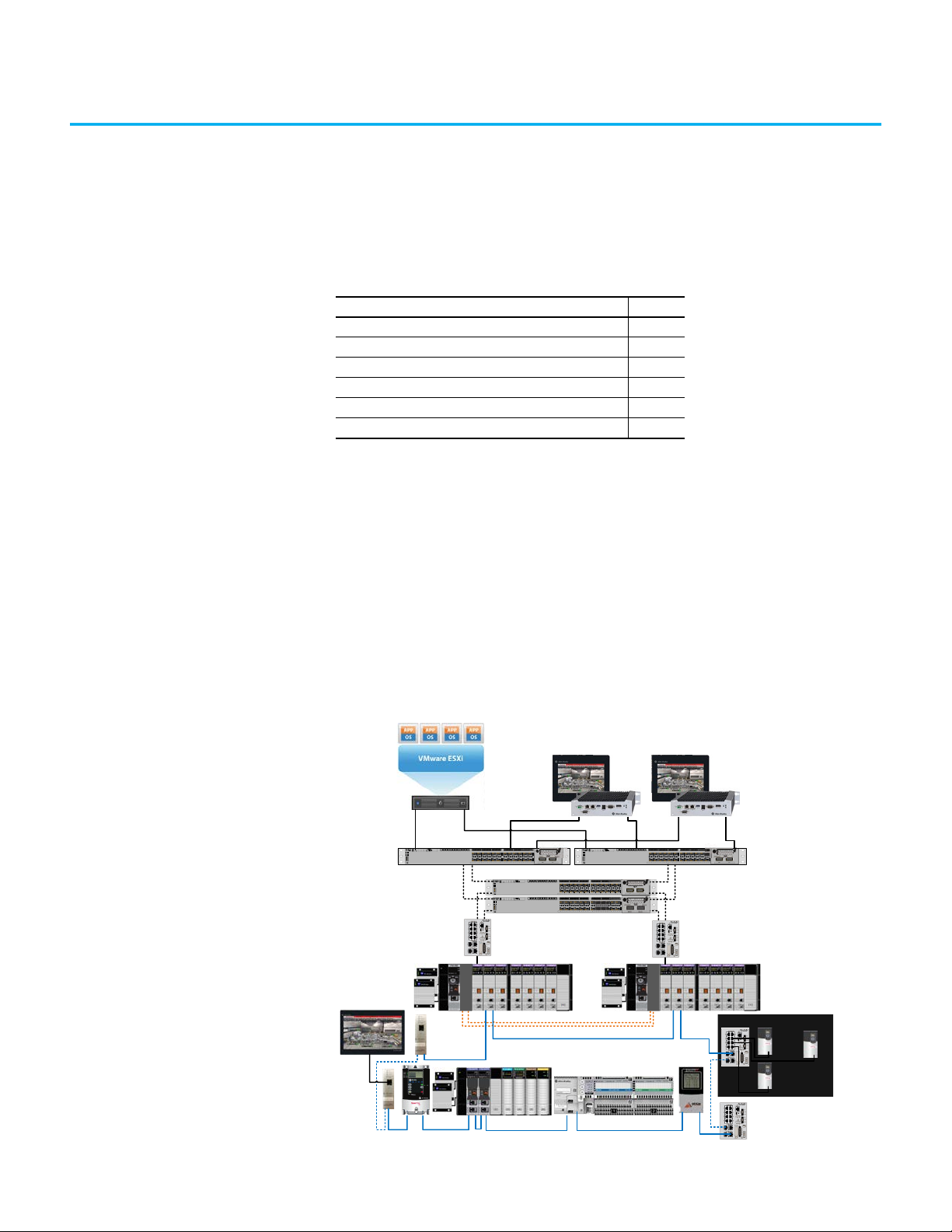
The ControlLogix® 5580 high availability system uses a redundant chassis pair
to maintain process operation when events occur that stop process operation
on non-redundant systems, such as a fault on a controller.
The redundant chassis pair includes two synchronized ControlLogix chassis
with specific, identical components in each. For example, one redundancy
module and at least one EtherNet/IP™ communication module are required.
Controllers are typically used in redundancy systems, but are not required if
your application only requires communication redundancy. Your application
operates from a primary chassis, but can switch over to the secondary chassis
and components if necessary.
NETWOR
2Q
40G 1
01 12 13 24
40G 2
01 12 13 24
01 12 13 24
NETWORK MODULE
Catalyst 9300 24S
NET
01 12 13 24
C9300-NM-2Q
40G 1
40G 2
2Q
40G 1
40G 2
40G 1
40G 2
Rockwell Automation Publication 1756-UM015B-EN-P - February 2021 11
Page 12

Chapter 1 ControlLogix 5580 High Availability Systems
Features of the ControlLogix 5580 High Availability System
The software and hardware components that are required to configure and use
a ControlLogix 5580 high availability system provide these features:
• All non-safety ControlLogix 5580 controller catalog numbers are
supported.
• ControlLogix 5580 redundant controllers use the same controller
firmware revision as standard controllers.
• Configure a redundant controller with a checkbox on the Controller
Properties dialog box in Studio 5000 Logix Designer application
software.
• Partnered sets of 1756-RM2 modules can reach speeds as fast as
1000 Mbps.
• Redundant fiber ports for crossloading; no single point of failure of a
fiber cable.
• Plug-and-play-style commissioning and configuration that does not
require extensive programming.
• Support for produced unicast connections.
• EtherNet/IP network for the redundant chassis pair.
• Support for Device-level Ring (DLR) and Parallel Redundancy Protocol
(PRP) networks.
• Easy-to-use, fiber-optic communication cable that connects redundant
chassis pairs.
• A redundancy system ready to command and monitor the redundant
system states after basic installation, connection, and powerup.
• Switchovers occur as fast as 20 ms.
• Support for FactoryTalk® applications for Ethernet communication
modules including, but not limited to:
- FactoryTalk Alarms and Events
- FactoryTalk Batch
- FactoryTalk PhaseManager™
• Logix tag-based alarms considerations:
- ControlLogix 5580 controllers support up to 7500 Logix tag-based
alarms per software guidelines.
• Logix instruction-based alarms considerations:
- ControlLogix 5580 controllers support up to 3000 Logix instruction-
based alarms with 3000 burst.
• Support for CIP Sync™ technology over an EtherNet/IP network to
establish time coordination across the redundant system.
• Access to remote I/O modules over an EtherNet/IP network.
• Access to 1715 Redundant I/O systems over an EtherNet/IP network.
• Supports FLEX 5000 I/O.
• Supports PhaseManager.
• Supports DLR topologies with the use of an EtherNet/IP communication
module. For more information about DLR, see the EtherNet/IP Device
Level Ring Application Technique, publication ENET-AT007
• Sockets are supported in the 1756-EN2T, 1756-EN2TP, 1756-EN2TR and
1756-EN2F modules, firmware revision 5.008 or later. For additional
information, see the EtherNet/IP Socket Interface Application
Technique, publication ENET-AT002
• For information on how to best organize a process application, see the
PlantPAx DCS Configuration and Implementation User Manual
publication PROCES-UM100
12 Rockwell Automation Publication 1756-UM015B-EN-P - February 2021
.
.
.
Page 13

Chapter 1 ControlLogix 5580 High Availability Systems
Features Not Supported
• Compact 5000 I/O
• The embedded Gigabit Ethernet port of the controller.
• DeviceNet
• Messaging to PLC2, PLC3, PLC5, SLC, and other legacy controllers.
• IEC62443-4-2 secure communications
• License-based Source and Execution Protection
• Any motion feature
• Firmware Supervisor
•Event Tasks
• Input or consumed unicast connections
• SequenceManager
(1)
, ControlNet, RIO, DH+ networks
IMPORTANT
For Ethernet modules, signed and unsigned firmware are available.
Signed modules provide the assurance that only validated firmware can
be upgraded into a module.
Signed and unsigned firmware:
• Both signed and unsigned firmware are available.
• Product is shipped with unsigned firmware. To obtain signed firmware,
you must upgrade the firmware for your product.
• To obtain signed and unsigned firmware, go to
http://www.rockwellautomation.com/global/support/firmware/
overview.page.
• Once signed firmware is installed, subsequent firmware updates must be
signed also.
There are no functional/feature differences between signed and
unsigned communication modules.
Controller Keyswitch The position of the keyswitch on the controllers in both chassis must match
(both in REM or both in RUN). There should NOT be a mismatch. See
Knowledgebase Technote Processor Key Switches in ControlLogix Redundancy
System.
For more information on operation modes of the controller see Choose the
Controller Operation Mode in the ControlLogix 5580 and GuardLogix 5580
Controllers User Manual, publication 1756-UM543
.
(1) DeviceNet modules are supported if accessed across an Ethernet bridge but may experience
a bump during a ControlLogix Redundancy switchover.
Rockwell Automation Publication 1756-UM015B-EN-P - February 2021 13
Page 14

Chapter 1 ControlLogix 5580 High Availability Systems
Redundancy System Components
Communication between a redundant chassis pair that includes matching
components makes redundancy possible.
Each chassis in the redundant chassis pair contains these ControlLogix
components:
• One ControlLogix power supply - Required
• One ControlLogix 1756-RM2 redundancy module - Required
Redundancy modules link the redundant chassis pair to monitor events
in each chassis and initiate system responses as required.
• At least one ControlLogix EtherNet/IP communication module - up to
seven, optional (any combination)
• One ControlLogix 5580 controller.
If the chassis is used as a redundant gateway, then a controller is not
required.
In addition, redundant chassis are connected to other components outside the
redundant chassis pair, for example, remote I/O chassis or human machine
interfaces (HMIs).
For more information about components you can use in a redundancy system,
see the High Availability System Reference Manual, publication
HIGHAV-RM002
.
I/O Modules in Redundancy Systems
A ControlLogix 5580 redundancy system supports I/O modules in a remote
chassis connected via EtherNet/IP. You cannot use I/O modules in the
redundant chassis pair.
You can put DeviceNet modules in a remote rack but DeviceNet devices will
not be bumpless during a switchover event.
14 Rockwell Automation Publication 1756-UM015B-EN-P - February 2021
Page 15

Chapter 1 ControlLogix 5580 High Availability Systems
Fiber-optic Cable If you choose to make your own fiber-optic cables, consider the following:
• Fiber-optic Communication Cable Specifications:
Attribute 1756-RM2 1756-RM2XT
Temperature, operating 0…60 °C (32…140 °F) -25…70 °C (-13…158 °F)
Connector type LC-type (fiber-optic)
Cable type 8.5/125 micron single-mode fiber-optic cable
Channels 1 (transmit and receive fiber)
Length, max 10 km (10,000 m, 10936.13 yd
Transmission 1000 Mbps
Wavelength 1310 nm
SFP transceiver
• Determine Optical Power Budget
You can determine the maximum optical-power budget in decibels (dB)
for a fiber-optic link by computing the difference between the minimum
transmitter-output optical power (dBm avg) and the lowest receiver
sensitivity (dBm avg). As shown in Table 1
budget for the 1756-RM2 module is -9.5 - (-19) or 9.5 dB.
Transceiver Rockwell Automation PN-91972
Connector/cable: LC duplex connector, 1000BASE-LX-compliant
, the maximum optical power
The optical-power budget provides the necessary optical-signal range to
establish a working fiber-optic link. You must account for the cable
lengths and the corresponding link penalties. All penalties that affect the
link performance must be accounted for within the link optical power
budget.
Table 1 - Optical Power Budget Ranges for 1756-RM2 and 1756-RM2XT Modules
Transmitter Min Typical Max Unit
Output optical power -9.5 — -3 dBm
Wavelength 1270 — 1355 nm
Receiver Min Typical Max Unit
Receiver sensitivity — — -19 dBm
Receiver overload — — -3 dbm
Input operating wavelength 1270 — 1355 nm
Use Dual Fiber Ports with the 1756-RM2 Redundancy Module
The dual fiber ports of the 1756-RM2 module constitute a redundant pair of
communication channels between the partner 1756-RM2 modules in a
redundant chassis pair. One of the channels is termed as 'ACTIVE', while the
other channel is termed as 'REDUNDANT'. All data communication between
the partner redundancy modules is conducted exclusively over the ACTIVE
channel. If or when the ACTIVE channel fails, a 'Fiber Channel Switchover' is
initiated automatically and all data communication shifts to the REDUNDANT
channel, which then becomes the new ACTIVE channel.
Rockwell Automation Publication 1756-UM015B-EN-P - February 2021 15
Page 16

Chapter 1 ControlLogix 5580 High Availability Systems
Fiber Channel Switchover
Due to the fiber channel switchover, the redundant chassis pair remains
synchronized even after a failure of the ACTIVE channel. Any of the following
failures of the ACTIVE channel trigger an automatic fiber channel switchover
to the REDUNDANT channel, provided the REDUNDANT channel is still
operating in a normal condition:
• Signal attenuation along the fiber cable path that is routed between the
• A broken or damaged fiber cable that is routed between the partner
• Improper or loosely fit cable connector
• SFP transceiver fault
• Removal or loose connection of the SFP transceiver
• Data communication error (signaled by a failed CRC check)
Chassis synchronization is lost only when both of the channels have failed or
are disconnected.
The fiber channel switchover can occasionally extend the completion of data
communication packets between the partner redundancy modules. Therefore,
the scan time of the controller can occasionally experience a delay of 10 ms or
less.
partner redundancy modules
redundancy modules
Configuration
The use of dual fiber ports is entirely ‘plug and play’. There is no user
configuration that is needed for any of the operations of the active and
redundant channels. The firmware automatically manages the selection of
active and redundant channels. The dual fiber cables between the partner
redundancy modules can be crossed over between CH1 and CH2 without any
restriction, however, this is not recommended as it can complicate
troubleshooting.
Monitoring and Repair
Synchronization is preserved if the REDUNDANT channel has failed or is
being repaired. The repair of the REDUNDANT channel can be performed
online while the redundant chassis pair is running synchronized. To aid online
repairs, the fiber cable connections and SFP transceiver can be removed and
inserted under power.
It is not mandatory to use the REDUNDANT channel that is connected
between the two redundancy modules. The redundant chassis pair can be
synchronized with just one of the channels connected. The REDUNDANT
channel can be installed later while the chassis is running synchronized.
The status indicators on the front panel and the indicators and counters that
are displayed in the RMCT provide monitoring of the channel status.
16 Rockwell Automation Publication 1756-UM015B-EN-P - February 2021
Page 17

Chapter 1 ControlLogix 5580 High Availability Systems
Redundancy System Operations
Once the redundancy modules in the redundant chassis pair are connected
and powered, they determine which chassis is the primary chassis and which is
the secondary chassis.
The redundancy modules in both the primary and secondary chassis monitor
events that occur in each of the redundant chassis. If certain faults occur in the
primary chassis, the redundancy modules execute a switchover to the
unfaulted, secondary chassis.
System Qualification and Synchronization
When the redundant system is first started, the redundancy modules run
checks on the redundant chassis. These checks determine if the chassis
contain the appropriate modules and firmware to establish a redundant
system. This stage of checks is referred to as qualification.
After the redundancy modules complete qualification, synchronization can
take place. Synchronization is a state in which the redundancy modules
execute these tasks:
• Verify that the connection between redundancy modules is ready to
facilitate a switchover
• Verify that the redundant chassis continue to meet qualification
requirements
• Synchronize the data between the redundant controllers, also called
crossloading
This data is crossloaded:
- Updated tag values
-Forced values
- Online edits
- Other project information
Synchronization always takes place immediately following qualification. Also,
depending on your system configuration, synchronization takes place at the
end of each program that is run within the controller project, or at other
intervals that you specify.
Some communication delays can occur during qualification. The existence and
duration of these delays depend on:
• Quantity and types of tags on scan in FactoryTalk Linx software
• Client screen and tag update rates (for example, FactoryTalk Live Data/
FactoryTalk Historian)
• Number of data subscribers (for example, FactoryTalk Alarms and
Events, FactoryTalk Batch, and so on)
• Size of the redundant controller application
•Network traffic
Rockwell Automation Publication 1756-UM015B-EN-P - February 2021 17
Page 18

Chapter 1 ControlLogix 5580 High Availability Systems
Switchovers
During redundant system operation, if certain conditions occur on the
primary chassis, primary control is switched to the secondary chassis. These
conditions cause a switchover:
• Loss of power
• Major fault on the controller
• Removal or insertion of any module
• Failure of any module
• Loss of an EtherNet/IP connection - This event only causes a switchover
• A program-prompted command to switchover
• A command that is issued via the Redundancy Module Configuration
After a switchover occurs, the new primary controller continues to execute
programs. For more information about how tasks execute after a switchover,
see Crossloads, Synchronization, and Switchovers
if it results in the EtherNet/IP communication module transition to a
lonely state, that is, the module does not see any devices on the network.
Tool (RMCT)
on page 61.
IMPORTANT
It is required that all messaging communications point to the primary
controller when reading/writing to a ControlLogix Redundancy system.
Do not target message instructions to modules in the secondary
chassis.
Your application can require some programming considerations and potential
changes to accommodate a switchover. For more information on these
considerations, see Chapter 6
IMPORTANT
During a switchover of the fiber channels of the 1756-RM2 module, scan
, Programming Best Practices on page 71.
time encounters a delay of ~10 ms; however, the chassis always remains
synched.
Data Server Communication Recovery Time Reduction During a Switchover
Brief communication interruption occurs between FactoryTalk Linx software
and the redundant chassis pair when a switchover occurs. After the switchover
is complete, communication resumes automatically.
Data server communication recovery time is the time during a switchover
from primary to secondary, when tag data from the controller is unavailable
for reading or writing. Data server communication recovery time applies to
any software that uses tag data, such as HMI displays, data loggers, alarms
systems, or historians. Data server communication recovery time reduction is
important to increase the availability of the system.
When you configure the connection between a FactoryTalk Linx data server,
and a redundant ControlLogix controller, you can configure redundant
shortcut paths to the primary and secondary controllers. These shortcut paths
help reduce data server communication recovery time that occurs during a
redundancy switchover.
18 Rockwell Automation Publication 1756-UM015B-EN-P - February 2021
Page 19

Chapter 1 ControlLogix 5580 High Availability Systems
The following are required to take advantage of this:
• A dedicated pair of ControlLogix communication modules with firmware
revision 11.002 or later (1756-EN2TP, 1756-EN2TR, 1756-EN2T), that do
not swap IP addresses. See Do Not Use IP Address Swapping
• ControlLogix 5580 redundancy controllers with redundancy firmware
revision 33.011 or later
• FactoryTalk Linx 6.00 with the FactoryTalk Linx patch available from
Knowledgebase Technote Patch: FactoryTalk Linx 6.00 patch required to
support ControlLogix V31.05 Redundancy, or later versions of FactoryTalk
Linx.
• Redundant ControlLogix Controller shortcut type in FactoryTalk Linx
that points to the Primary and Secondary controllers through the
communication modules, without swapping IP addresses. For
information on shortcuts in FactoryTalk Linx, see the FactoryTalk Linx
Getting Results Guide, publication LNXENT-GR001
.
on page 30.
Restrictions There are restrictions that you must consider when using a redundancy
system. Most of these restrictions apply to all redundancy system revisions.
Exceptions are noted:
• See the release notes of the redundancy bundles for compatible products,
versions, and revisions
• The redundant controller program cannot contain these tasks:
-Event tasks
-Inhibited tasks
For recommendations and requirements that are related to
programming the redundant controller, see Programming Best
Practices on page 71.
• You cannot use the Match Project to Controller feature available in
Studio 5000 Logix Designer® in a redundancy system.
• You cannot use motion in a redundant controller program.
• You cannot use SequenceManager.
• You cannot use consumed unicast connections in a redundancy system.
You can use produced unicast connections that remote consumers
consume.
• Outputs controlled by IOT instructions are not guaranteed to maintain a
bumpless transition during a switchover. Due to this, it is recommended
to avoid using IOT instructions within a redundancy system.
• The HMIBC instruction is not supported in a redundancy system.
• You can use one controller of the same family, and seven EtherNet/IP
communication modules in each chassis of a redundant chassis pair.
• Cannot use Listen Only or Input Only connections for FLEX 5000 I/O
and ControlLogix 1756 HART I/O from a redundant controller.
- There is no ability for another controller to listen or dual-own
connections to FLEX 5000 I/O.
- This means no sharing of FLEX 5000 I/O or Highly Integrated HART
between a the redundant controller pair and other controllers.
Rockwell Automation Publication 1756-UM015B-EN-P - February 2021 19
Page 20

Chapter 1 ControlLogix 5580 High Availability Systems
Notes:
20 Rockwell Automation Publication 1756-UM015B-EN-P - February 2021
Page 21

Chapter 2
Configure the Redundancy System
Top ic Pa ge
Before You Begin 21
Download the Redundancy Firmware Bundle 22
Install the Firmware Bundle 22
Install the Redundancy Module Configuration Tool 22
Install the Redundancy System 23
Configure Redundant Firmware 24
Set the initial Primary and Secondary Chassis 25
Before You Begin Complete these tasks before you configure the redundancy system:
IMPORTANT
For best performance, place the redundancy module in the
chassis as close as possible to the controller.
• Read and understand the safety and environmental considerations
explained in the installation instructions publication for each
component.
• Order a 1756-RMCx fiber-optic communication cable if you do not have
one.
• If you choose to make your own fiber-optic cable for lengths that the
1756-RMCx catalog numbers do not support, refer to Fiber-optic Cable
on
page 15.
• Download and install the compatible versions of the Studio 5000 Logix
Designer® application, RSLinx® Classic or FactoryTalk® Linx
communication software, and ControlFLASH Plus™ software.
For information on how to download and install ControlFLASH Plus
software, see the ControlFLASH Plus Quick Start Guide, publication
CFP-QS001
IMPORTANT
If RSLinx Classic software or FactoryTalk Linx is already on your system,
make sure to shut it down before installing/upgrading software.
• Review the release notes for the firmware bundle that you are installing.
Make sure that you have compatible hardware and the correct firmware
revisions.
• Determine the IP address for each of your Ethernet/IP™ communication
modules. Both Ethernet/IP communication modules of the redundant
chassis pair will usually have the same IP address. See IP Address
Swapping on page 29.
• System scan time will likely be different between a synchronized and
unsynchronized system. See Crossloads, Synchronization, and
Switchovers on page 61
Rockwell Automation Publication 1756-UM015B-EN-P - February 2021 21
Page 22

Chapter 2 Configure the Redundancy System
Download the Redundancy Firmware Bundle
You can download the appropriate redundancy firmware bundle from the
Rockwell Automation Product Compatibility and Download Center (PCDC).
1. Go to https://compatibility.rockwellautomation.com/Pages/home.aspx
2. Search for ‘1756-L8x Redundancy Bundle’.
3. Select and download the appropriate bundle revision.
The Redundancy Module Configuration Tool (RMCT) is included in the
redundancy bundle download, and is not available for separate download.
Install the Firmware Bundle Follow the steps in this section.
Create a firmware directory on your computer first, so you can unzip the files to
this directory.
1. You must first shut down RSLinx Classic software.
2. Browse to the location of the redundancy firmware revision bundle.
3. Unzip the redundancy firmware bundle on your computer. After you
unzip, you will have these files:
•Firmware: Vxx.0xx_kitx_5580CLXRED Bundle.dmk (where x is the
firmware revision and kit number)
• Redundancy Module Configuration Tool
4. Unzip the Redundancy Module Configuration Tool on your computer.
.
Install the Redundancy Module Configuration Tool
The RMCT version that is compatible with your redundancy module firmware
is included in the downloads for the redundancy bundle, and is not available as
a separate download.
IMPORTANT
To install the RMCT:
1. Browse to the RMCT directory on your computer.
2. Double-click setup.exe.
3. On the RMCT Setup dialog, click Next.
4. When the installation is complete, click Finish.
You must uninstall any existing version of the Redundancy Module
Configuration Tool (RMCT) before you install the RMCT, version 8.06.03 or
later. If you do not uninstall the previous version, you can have difficulty
if you try to uninstall version 8.06.03 or later at another time.
22 Rockwell Automation Publication 1756-UM015B-EN-P - February 2021
Page 23

Chapter 2 Configure the Redundancy System
Install the Redundancy System
If you need to install the redundancy system, determine the location of your
controller, Ethernet/IP communication modules, and redundancy modules in
both chassis of the system, matching partners slot for slot.
IMPORTANT
1. Install the first chassis and power supply (or redundant power supplies):
• ControlLogix® Chassis Installation Instructions, publication
1756-IN621
• ControlLogix Power Supply Installation Instructions, publication
1756-IN619
• ControlLogix Redundant Power Supply Installation Instructions,
publication 1756-IN620
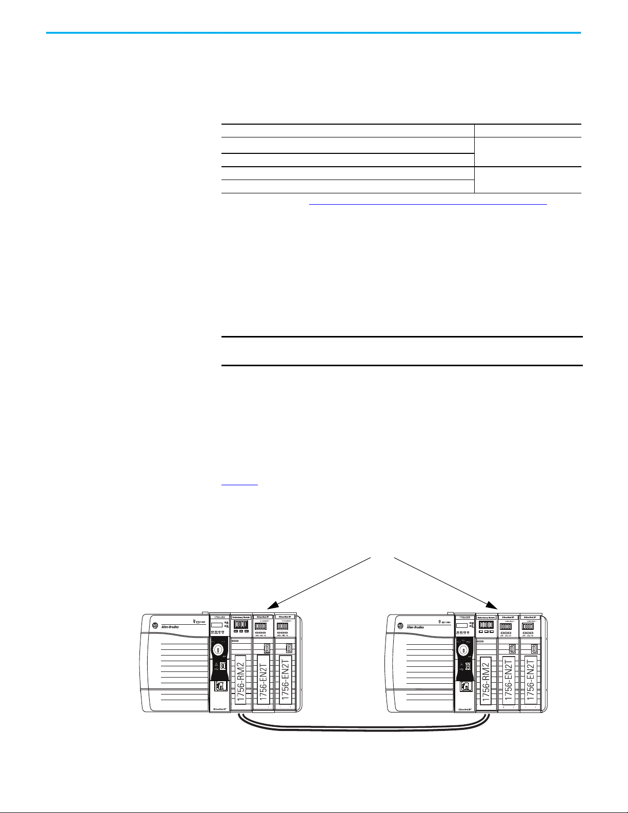
2. Install and connect the 1756-RM2 redundancy modules in both chassis:
• ControlLogix Redundancy Modules Installation Instructions,
publication 1756-IN087
3. Install the first chassis Ethernet/IP communication modules:
• 1756 EtherNet/IP Communication Modules Installation Instructions,
publication 1756-IN050
4. Install one controller in the first chassis of the redundant pair:
• ControlLogix 5580 Controllers Installation Instructions, publication
1756-IN043
5. Install the second chassis and power supply (or redundant power
supplies).
6. Install the second chassis Ethernet/IP communication modules.
7. Install one controller in the second chassis of the redundant pair.
Do not power on either chassis until you have installed all modules in
both chassis.
.
Rockwell Automation Publication 1756-UM015B-EN-P - February 2021 23
Page 24

Chapter 2 Configure the Redundancy System
Configure Redundant Firmware
Use ControlFLASH Plus software to upgrade the firmware of each module in
each chassis. For information on how to download, install, and use
ControlFLASH Plus software, see the ControlFLASH Plus Quick Start Guide,
publication CFP-QS001
IMPORTANT
• Apply power ONLY to the chassis that contains modules on which you are
• Redundancy module firmware that is contained in the redundancy
• All modules in both chassis must use firmware as defined in the 1756-L8x
.
upgrading firmware.
system firmware bundle is designed for use with the 1756-RM2 and 1756RM2XT redundancy modules.
Redundancy Bundle.
Upgrade the Firmware in the First Chassis
IMPORTANT
Complete these steps to upgrade the firmware in the first chassis.
1. Apply power to the chassis.
2. Set the keyswitch on the controller to PROG.
Redundancy module firmware that is contained in the redundancy
system firmware bundle is designed for use with the 1756-RM2 and
1756-RM2XT redundancy modules.
3. Wait for the modules to complete their start-up scroll messages. Check
Module and status indicators. During this time, the redundancy module
conducts internal operations to prepare for an update.
Create a firmware directory on your computer first, so you can unzip the files to
this directory.
4. Launch ControlFLASH Plus software, and upgrade the Ethernet
communication module that you going to use as the gateway to the other
modules.
5. Upgrade the 1756-RM2 redundancy module.
6. Once the firmware upgrade is complete, verify that the redundancy
module status displays PRIM, which indicates a successful upgrade.
7. Use ControlFLASH Plus software to upgrade the rest of the modules in
the chassis.
IMPORTANT
• Verify the firmware revision of each module to make sure it matches the
revision in the 1756-L8x Redundancy Bundle.
• Power off the first chassis after you have verified a successful update of
each module.
24 Rockwell Automation Publication 1756-UM015B-EN-P - February 2021
Page 25

Chapter 2 Configure the Redundancy System
Upgrade the Firmware in the Second Chassis
Complete these steps to update the firmware for the modules in the second
chassis.
1. Apply power to the second chassis.
2. Set the keyswitch on the controller to PROG.
3. Complete steps 3
beginning on page 24
…7 in section Upgrade the Firmware in the First Chassis
for the modules in the second chassis.
Set the initial Primary and Secondary Chassis
IMPORTANT
Power on the chassis you want to set as the initial primary chassis first. After
you have applied power, verify all module pairs are at compatible firmware
revision levels.
IMPORTANT
Complete these steps to designate the primary and secondary chassis of a
redundant pair.
• verify the firmware revision of each module to make sure it matches the
revision in the 1756-L8x Redundancy Bundle.
• Power off the second chassis after you have verified a successful update
of each module.
• Do not apply power to the chassis until you have read the instructions
for designating the primary chassis. Applying power to the chassis in
the correct order is crucial to designating the primary and secondary
chassis.
• Make sure both Ethernet/IP communication modules are set
appropriately. See Data Server Communication Recovery Time
Reduction During a Switchover on page 18.
• It is not recommended to load an application image until the primary
and secondary racks are synchronized.
• Before you set the initial primary chassis and qualify the system, it is
recommended to have the latest firmware installed. See Configure
Redundant Firmware on page 24.
1. Verify that power is removed from both chassis.
2. Apply power to the chassis you want to designate as the primary chassis
and wait for the status indicators of the module to display PRIM.
3. Apply power to the chassis you want to designate as the secondary
chassis.
4. Verify primary and secondary chassis designations by viewing the
redundancy module status displays.
See Redundancy Module Status Indicators
redundancy module display information.
IMPORTANT
Rockwell Automation Publication 1756-UM015B-EN-P - February 2021 25
If both modules have power applied to them simultaneously, the module
with the lowest IP address is designated as the primary chassis and
displays PRIM on the four-character display of the module. In addition,
the PRI status indicator on the primary redundancy module is green. The
secondary chassis displays either DISQ or SYNC, depending on the state
of the secondary chassis. In addition, the PRI status light on the
secondary redundancy module is not illuminated.
on page 138 for specific
Page 26

Chapter 2 Configure the Redundancy System
After Designation
When you first apply power to the primary and secondary chassis,
compatibility checks are carried out between the redundant chassis. Then,
because the default Auto-Synchronization parameter is set to Always,
qualification begins.
While the qualification occurs, the module status display transitions from DISQ
(disqualified) to QFNG (qualifying) to SYNC (synchronized). The qualification
completes in 1…3 minutes and the module status display indicates the
qualification status.
After you verify the system is synchronized, you can download the user
application to the primary controller. It automatically crossloads to the
secondary controller.
Use this table as a reference when interpreting the qualification status of the
modules that are displayed on the module status display.
Module Status Display Interpretation
QFNG Qualification processes are in progress.
SYNC displays after qualification processes are complete.
SYNC
DISQ…QFNG…DISQ
This indicates that chassis configuration and the firmware revision levels are
compatible and that the secondary chassis is ready to assume control if there is a
major fault in the primary chassis.
If DISQ continues to display after about 3 minutes, check the following:
• Incorrect chassis configuration. That is, incompatible hardware is used.
• Incompatible firmware revisions are used between the primary and secondary
modules.
• The partnered EtherNet/IP modules are not set to the same IP Configuration.
• The Auto-Synchronization parameter within the Redundancy Module Configuration
Tool is set to Never or Conditional (default setting).
Conversion from a Non-redundant to a Redundant System
To upgrade a standalone chassis to a redundant chassis pair:
1. Insert a redundancy module in a spare slot in the standalone chassis, and
2. Configure an identical chassis with compatible modules in the same slot
as the standalone chassis (including the redundancy module).
A partnered chassis that is set as the secondary chassis stops functioning if it
contains:
• non-redundancy-compliant modules
• modules not compatible with redundancy
• non-redundancy-compliant firmware
For more information, see Convert from a Non-redundant System
on page 143.
26 Rockwell Automation Publication 1756-UM015B-EN-P - February 2021
Page 27
Chapter 2 Configure the Redundancy System
Qualification Status Via the RMCT
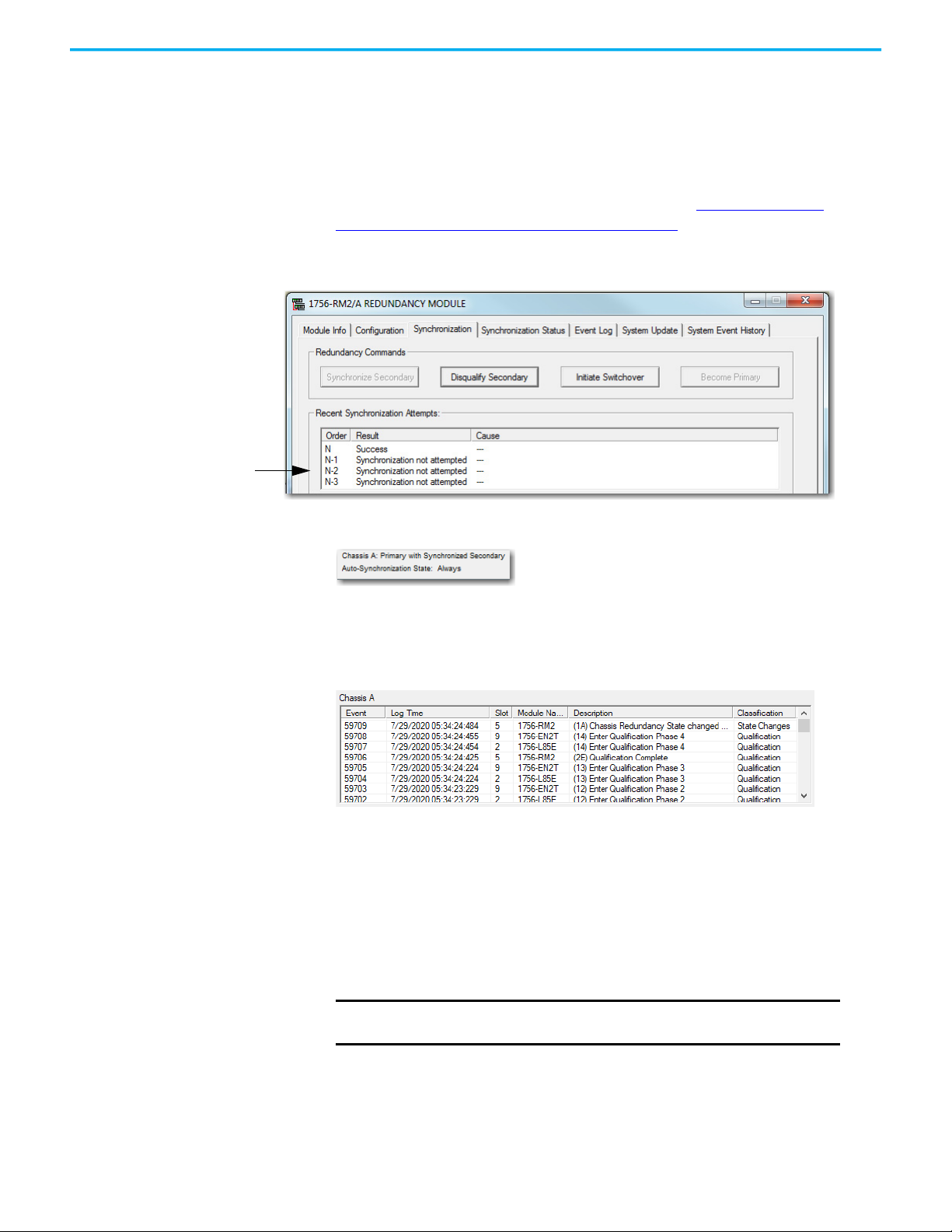
To view the details for a qualification attempt, access the Synchronization or
Synchronization Status tabs of the RMCT. These tabs provide information
about qualification attempts and redundant chassis compatibility.
For more information on how to use the RMCT, see Use the RMCT for
Synchronization Attempts and Status on page 111.
RMCT Synchronization Status Tab
Synchronization Status Tab for Chassis Compatibility
You can also view events specific to qualification in the Event Log of the RMCT.
Event Log with Qualification Events
Reset the Redundancy Module
There are two ways to reset the module.
• Cycle power to the chassis.
• Remove the module from the chassis and reinsert the module.
IMPORTANT
Do not choose to cycle power to the chassis if it causes you to
lose control of your process.
Rockwell Automation Publication 1756-UM015B-EN-P - February 2021 27
Page 28

Chapter 2 Configure the Redundancy System
Remove or Replace the Redundancy Module
IMPORTANT
If you remove the redundancy module, you will lose
redundancy functionality.
To remove or replace the redundancy module, follow these steps.
1. To disengage the upper and lower module tabs, push them.
2. Slide the module out of the chassis.
3. Insert the replacement in the same slot and move the fiber cable(s) to the
new module.
IMPORTANT
If you want to resume system operation with an identical
module, you must install the new module in the same slot.
28 Rockwell Automation Publication 1756-UM015B-EN-P - February 2021
Page 29

Configure the EtherNet/IP Network
Top ic Pa ge
Requested Packet Interval (RPI) 29
IP Address Swapping 29
CIP Sync 33
Produce/Consume Connections 35
Configure EtherNet/IP Communication Modules in a Redundant System 37
Use a Redundancy System with Device Level Ring 38
Use a Redundancy System with Parallel Redundancy Protocol 38
Chapter 3
Requested Packet Interval (RPI)
The RPI for I/O connections in a redundant-enabled controller tree are
configured the same way as a with a simplex controller. Adjusting the RPI rates
of I/O connections impact the loading of the associated EtherNet/IP
communications modules.
The RPI for I/O connections in a redundant-enabled controller tree are
configured the same way as a with a simplex controller. Adjusting the RPI rates
of I/O connections impact the loading of the associated EtherNet/IP
communications modules.
This table describes CPU usage for EtherNet/IP™ communication modules.
If the CPU utilization
percent is
0…80%
Greater than 80%
Then
No action is required.
Important: This range is the optimal rate.
• Take steps to reduce your CPU utilization. See the EtherNet/IP Network Configuration User
Manual, publication ENET-UM001
• Adjust the requested packet interval (RPI) of your connection.
• Reduce the number of devices that are connected to your module.
• Add another Ethernet module to the redundant chassis pair (maximum of 7)
Important: Your EtherNet/IP communication module can function at 100% CPU
capacity, but at or near this rate, you run the risk of CPU saturation and
performance degredation.
.
IP Address Swapping IP address swapping is a feature available to EtherNet/IP communication
modules in a redundancy system where a partnered set of EtherNet/IP
communication modules swap IP addresses during a switchover.
IMPORTANT
Rockwell Automation Publication 1756-UM015B-EN-P - February 2021 29
You must use IP address swapping to use remote I/O and
produce/consume connections of an EtherNet/IP network.
Page 30
Chapter 3 Configure the EtherNet/IP Network
Primary chassis Secondary Chassis
Assigned IP Address: 192.168.1.3
Determine Use of IP Address Swapping
Depending on your EtherNet/IP network configuration, you can choose to use
IP address swapping between your partnered EtherNet/IP communication
modules in the event of a switchover.
If you want to Then
Minimize data server communication recovery time during switchover
Have your partnered EtherNet/IP communication modules on different subnets
Use Remote I/O or produce/consume
Have your partnered EtherNet/IP communication modules on the same subnet.
(1) For more information, see Data Server Communication Recovery Time Reduction During a Switchover on page 18
(1)
Do not use IP address swapping
Use IP address swapping
If you are using different subnets, you are responsible for programming your
system to use the address and subnet of the new primary chassis in the event
of a switchover.
Do Not Use IP Address Swapping
If you do not use IP address swapping, assign unique values for the IP address
on both EtherNet/IP communication modules in the partnered set:
IMPORTANT
The IP address cannot be of the following format between the partner
EtherNet modules: aaa.bbb.ccc.ddd & aaa.bbb.ccc.(ddd+1)
Use IP Address Swapping
If you use IP address swapping, at minimum, the below parameters must be
configured on both EtherNet/IP communication modules in the partnered set:
• IP address
•Subnet mask
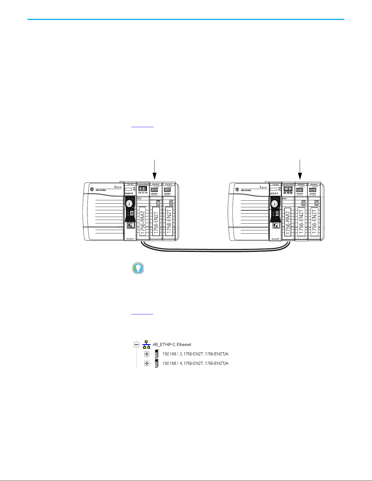
Figure 1
initial configuration.
Figure 1 - IP Addresses of EtherNet/IP Communication Modules During System Configuration
shows a partnered set of EtherNet/IP communication modules during
CH2 CH1 OK
CH2 CH1 OK
30 Rockwell Automation Publication 1756-UM015B-EN-P - February 2021
Page 31
Chapter 3 Configure the EtherNet/IP Network
Primary Chassis Secondary Chassis
IP Address: 192.168.1.3
IP Address: 192.168.1.4
When a redundancy system begins operating, the primary EtherNet/IP
communication module uses the IP address that is assigned during initial
configuration. The secondary EtherNet/IP communication module
automatically changes its IP address to the next highest value. When a
switchover occurs, the EtherNet/IP communication modules swap IP
addresses.
For example, if you assign IP address 192.168.1.3 to both EtherNet/IP
communication modules in a partnered set, on initial system operation, the
secondary EtherNet/IP communication module automatically changes its IP
address to 192.168.1.4.
Figure 2
shows a partnered set of EtherNet/IP communication modules after
system operation begins.
Figure 2 - IP Addresses of EtherNet/IP Communication Modules After System Operation Begins
CH2 CH1 OK
CH2 CH1 OK
Do not assign IP addresses to EtherNet/IP communication modules outside the
partnered set to values that conflict with those values that are used in the
partnered set.
In the previous example, the partnered set uses 192.168.1.3 and 192.168.1.4. Use
192.168.1.5 or higher for all EtherNet/IP communication modules outside the
partnered set.
Figure 3 shows the partnered set of EtherNet/IP communication modules in
RSLinx® Classic software after system operation begins.
Figure 3 - IP Addresses in RSLinx Classic Software
Rockwell Automation Publication 1756-UM015B-EN-P - February 2021 31
Page 32

Chapter 3 Configure the EtherNet/IP Network
Static Versus Dynamic IP Addresses
A static IP address is manually assigned, and does not change. A dynamic IP
address is automatically assigned by a Dynamic Host Configuration Protocol
(DHCP) server, and can change over time.
We recommend that you use static IP addresses on EtherNet/IP
communication modules in redundancy systems. You cannot use dynamic IP
addresses with IP address swapping.
ATTENTION: If you use dynamic IP addresses and a power outage, or other
network failure occurs, modules that use dynamic IP addresses can be
assigned new addresses when the failure is resolved. If the IP addresses
change, your application could experience a loss of control or other serious
complications with your system.
Reset the IP Address for an EtherNet/IP Communication Module
If necessary, you can reset the IP address of a 1756-EN2x communication
module to the factory default value. To return to the factory default, set the
rotary switches on the module to 888 and cycle power.
After you cycle power to the EtherNet/IP communication module, you can
either set the switches on the module to the desired address, or set the
switches to 999 and use one of these methods to set the IP address:
• BOOTP-DHCP server
• RSLinx Classic communication software
• Studio 5000 Logix Designer® application
32 Rockwell Automation Publication 1756-UM015B-EN-P - February 2021
Page 33

Chapter 3 Configure the EtherNet/IP Network
CIP Sync CIP Sync™ provides a mechanism to synchronize clocks between controllers,
I/O devices, and other automation products in your architecture with minimal
user intervention.
CIP Sync uses Precision Time Protocol (PTP) to establish a
Master/Slave relationship among the clocks for each CIP Sync-enabled
component in the system. One master clock, which is known as the
Grandmaster, sets the clock to which all other devices on the network
synchronize their clocks.
IMPORTANT
Before you use this enhancement in a redundancy system, see these
publications for a full understanding of CIP Sync in any system:
• Integrated Architecture™ and CIP Sync Configuration Application
Technique, publication IA-AT003
Consider these points when you use CIP Sync in a redundancy system:
• If you enable CIP Sync Time Synchronization in the controllers in a
redundant chassis pair, you must also enable Time Synchronization in
one of the EtherNet/IP communication modules in the redundant
chassis pair so all devices have one path to the Grandmaster. To enable
Time Synchronization in the EtherNet/IP communication modules,
change the Time Sync Connection from None (default) to Time Sync and
Motion.
If time synchronization is enabled in any controller in the primary
chassis of a disqualified redundant chassis pair, and no other device in
the primary chassis has time synchronization enabled, the redundant
chassis pair attempts to qualify. However, in these application
conditions, the attempt to synchronize fails and the application will
remain in the qualifying state for up to 10 minutes before failing
qualification. If viewed in the RMCT, the system will remain at 85%
complete.
• While CIP Sync can handle multiple paths between master and slave
clocks, it resolves mastership most effectively if you configure the
redundant paths so that Time Synchronization is enabled in only the
minimum required number of EtherNet/IP communication modules.
We recommend that PTP should have exactly one path through the
system with no loops.
• If the primary controller is the Grandmaster, the redundancy system
automatically manages the CIP Sync clock attributes so that the
controller in the primary chassis is always set to be the Grandmaster
instead of the secondary controller.
IMPORTANT
We recommend to have the Grandmaster outside the RCP if possible. If
there are time sensitive devices that depend on the clock, there can be
a step in the PTP time during switchover.
• When a switchover occurs, these events take place:
- The Grandmaster status transfers from the original primary controller
to the new primary controller. This transfer can take longer to
complete than if Grandmaster status was transferred between devices
in a non-redundant system.
Rockwell Automation Publication 1756-UM015B-EN-P - February 2021 33
Page 34

Chapter 3 Configure the EtherNet/IP Network
G
M
S
S
S
S
S
M
P1
P1
S
S
S
S
S
M
S
M
S SS
M
S SS
P2
S
SS
M
Primary Chassis
CIP Sync
Stratix® 5700
Supervisory
CIP Sync
Secondary Chassis
Ethernet
CIP Sync
CIP Sync
CIP Sync
CIP Sync
CIP Sync
CIP Sync
CIP Sync
Ethernet
Fiber Optic Cable
G = Grandmaster (time source)
M = Master
S = Slave
P1 and P2 = Priorities
Stratix® 5700
CIP Sync
CIP Sync
CIP Sync
CIP Sync
CIP Sync
CIP Sync
Figure 4 - Redundancy System, using CIP Sync Technology
34 Rockwell Automation Publication 1756-UM015B-EN-P - February 2021
Page 35

Chapter 3 Configure the EtherNet/IP Network
CH2 CH1 OK
CH2 CH1 OK
Primary Chassis Secondary Chassis
Controller 1
Produced Tag
Controller 2
Consumed Tag
Produce/Consume Connections
Controllers let you produce (send) and consume (receive) system-shared tags
over an EtherNet/IP network.
IMPORTANT
A redundant controller can produce tags to a standard controller using
unicast or multicast. Redundant controllers must always consume tags
using multicast.
Example System Using Produced and Consumed Tags
These requirements exist when you use produced and consumed connections
over an EtherNet/IP network in a redundancy system:
• You cannot bridge produced and consumed tags over two networks. For
two controllers to share produced or consumed tags, both must be
attached to the same network.
• Produced and consumed tags use connections in both the controllers and
the communication modules being used.
• Because the use of produced and consumed tags uses connections, the
number of connections available for other tasks, such as the exchange of
I/O data, is reduced.
• The number of connections available in a system depends on controller
type and network communication modules used. Closely track the
number of produced and consumed connections to leave as many as
necessary for other system tasks.
• When configuring a tag that will be consumed by a redundant controller
pair, the tag configuration in both the remote controller (the producer)
and the consumer controller (the redundant ControlLogix® pair) must be
configured to be multicast.
Rockwell Automation Publication 1756-UM015B-EN-P - February 2021 35
Page 36

Chapter 3 Configure the EtherNet/IP Network
When configuring a tag that will be produced by a redundant controller
pair, the tag can be configured as multicast if there will be multiple
consumers or unicast if there is only a single consumer.
IMPORTANT
When you add an Ethernet module for the redundancy chassis to the I/O
tree of a remote consuming controller, change the Connection setting
from Rack Optimized to None. If this setting is not changed the
configured connection can briefly drop during a switchover.
Produced/Consumed Tags between Primary Controllers and Non-redundant Controllers
The connection from the remote controller to the redundant controller can
briefly drop during a switchover. This condition can occur if the EtherNet/IP
communication modules of the remote chassis do not use specific firmware
revisions. The controllers in the redundant chassis pair must also produce tags
over the EtherNet/IP network that the controllers in the remote chassis
consume.
Use these firmware revisions for EtherNet/IP communication modules in the
remote chassis to maintain connections during a switchover.
Table 2 - Minimum Firmware Revision for Communication Modules in Remote Chassis
EtherNet/IP Communication Module in Remote Chassis Minimum Firmware Revision
1756-EN2F
1756-EN2T
1756-EN2TR
1756-EN3TR
1756-ENBT 6.001
1768-ENBT 4.001
1769-L2x
1769-L3xE
1788-ENBT 3.001
IMPORTANT
The minimum firmware revisions that are listed in Table 2 apply
5.008 (unsigned)
5.028 (signed)
4.002
19.011
only to EtherNet/IP communication modules in the remote chassis.
In a redundant chassis pair, you can use only the ControlLogix
modules that are listed in the respective bundle's release notes.
36 Rockwell Automation Publication 1756-UM015B-EN-P - February 2021
Page 37

Chapter 3 Configure the EtherNet/IP Network
Configure EtherNet/IP Communication Modules in a Redundant System
Use these procedures to configure EtherNet/IP communication modules that
are used in redundant chassis.
Before You Begin
Before you begin configuring the EtherNet/IP communication modules in the
redundant chassis, verify that these tasks have been completed:
• The redundancy modules are installed and connected in the redundant
chassis.
• A plan for IP address use has been executed:
- If you are using IP address swapping, plan for the use of two
consecutive IP addresses in the partnered set.
- If you are not using IP address swapping, plan for the use of two IP
addresses.
• Know the subnet mask and gateway address for the Ethernet network
the redundant modules are to operate on.
Options for Setting the IP Addresses of EtherNet/IP Communication Modules
By default, ControlLogix EtherNet/IP communication modules ship with the
rotary switches set to 999 and with Bootstrap Protocol (BOOTP)/Dynamic Host
Configuration Protocol (DHCP)-enabled.
Use one of these tools to set the IP addresses for your EtherNet/IP
communication modules:
• Rotary switches on the module
• RSLinx Classic communication software
•Programming software
• BOOTP/DHCP utility
Half/Full Duplex Settings
The redundancy system uses the duplex settings of the EtherNet/IP
communication module that is the primary. After a switchover, the duplex
settings of the new primary EtherNet/IP communication module are used. By
default, the duplex setting is set to automatic. We recommend that you use
this setting whenever possible.
To avoid communication errors, configure both the primary and secondary
EtherNet/IP communication modules with the same duplex settings. If you
use different duplex settings on partnered EtherNet/IP communication
modules, then communication errors can occur after a switchover.
Rockwell Automation Publication 1756-UM015B-EN-P - February 2021 37
Page 38

Chapter 3 Configure the EtherNet/IP Network
Use a Redundancy System with Device Level Ring
Device Level Ring (DLR) is an EtherNet/IP protocol defined by ODVA, Inc. DLR
provides a means for detecting, managing, and recovering from single faults
in a ring-based network.
A DLR network includes the following types of ring nodes.
Node Description
A ring supervisor provides these functions:
• Manages traffic on the DLR network
• Collects diagnostic information for the network
A DLR network requires at least one node to be configured as ring supervisor.
IMPORTANT: By default, the supervisor function is disabled on supervisor-capable
devices, so they are ready to participate on a linear or star network or as a ring node on
Ring supervisor
Ring participants
Redundant gateways
(optional)
a DLR network.
In a DLR network, you must configure at least one of the supervisor-capable devices as
the ring supervisor before physically connecting the ring. If you do not, the DLR network
will not work.
We recommend to assign at least one supervisor outside of the redundant chassis pair
to prevent losing supervision of the DLR during switchover.
For more information on DLR operation see the EtherNet/IP Device Level Ring
Application Technique, publication ENET-AT007
Ring participants provide these functions:
• Process data that is transmitted over the network.
• Pass on the data to the next node on the network.
• Report fault locations to the active ring supervisor.
When a fault occurs on the DLR network, ring participants reconfigure themselves and
relearn the network topology.
Redundant gateways provide redundant paths from a DLR network to the outside
network.
.
Use a Redundancy System with Parallel Redundancy Protocol
Depending on their firmware capabilities, both devices and switches can
operate as supervisors or ring nodes on a DLR network. Only switches can
operate as redundant gateways.
For more information about DLR, see the EtherNet/IP Device Level Ring
Application Technique, publication ENET-AT007
.
Parallel Redundancy Protocol (PRP) is defined in international standard
IEC 62439-3 and provides high-availability in Ethernet networks. PRP
technology creates seamless redundancy by sending duplicate frames to two
independent network infrastructures, which are known as LAN A and LAN B.
A PRP network includes the following components.
Component Description
LAN A and LAN B Redundant, active Ethernet networks that operate in parallel.
Double attached node (DAN) An end device with PRP technology that connects to both LAN A and LAN B.
Single attached node (SAN)
Redundancy box (RedBox)
Virtual double attached node
(VDAN)
Infrastructure switch A switch that connects to either LAN A or LAN B and is not configured as a RedBox.
An end device without PRP technology that connects to either LAN A or LAN B.
A SAN does not have PRP redundancy.
A switch with PRP technology that connects devices without PRP technology to
both LAN A and LAN B.
An end device without PRP technology that connects to both LAN A and LAN B
through a RedBox.
A VDAN has PRP redundancy and appears to other nodes in the network as a DAN.
For more information about PRP topologies and configuration guidelines, see
the EtherNet/IP Parallel Redundancy Protocol Application Technique,
publication ENET-AT006
38 Rockwell Automation Publication 1756-UM015B-EN-P - February 2021
.
Page 39

Chapter 4
Configure the Redundancy Modules
Top ic Pa ge
Determine If Further Configuration Is Required 40
Configure the Redundancy Module 41
Module Info Tab 43
Configuration Tab 45
Synchronization Tab 47
Synchronization Status Tab 50
System Update Tab 51
The Redundancy Module Configuration Tool (RMCT) is used to configure the
redundancy modules and to determine the status of the redundancy system.
Use the RMCT to complete these configuration-related tasks:
• Set Auto-Synchronization parameters.
• Set the time and date of redundancy modules.
• View and set module information.
• View and set Chassis ID parameters (Chassis A, Chassis B).
• Lock the redundant system for an update.
• Conduct a test switchover.
You can also use this functionality available with the RMCT to determine the
status of the redundant system:
• View error diagnostics specific to redundant chassis.
• View qualification and compatibility status of partnered modules.
• Identify noncompliant modules for removal.
• View redundant system event history.
Rockwell Automation Publication 1756-UM015B-EN-P - February 2021 39
Page 40

Chapter 4 Configure the Redundancy Modules
Determine If Further Configuration Is Required
The default configuration of the redundancy modules lets you synchronize
your redundant chassis without additional configuration if you are using a
basic redundant chassis pair.
However, some applications and uses of the redundancy system can require
additional configuration. For example, you must use the RMCT for additional
configuration if you must complete any of these tasks:
• Set the redundancy modules to another time or date (recommended).
• Program your controller to control the redundant system.
• Change the redundancy synchronization options of the redundant
system.
• Change the synchronization states of your redundant chassis.
• Conduct a test switchover.
• Complete a firmware update of a module in the redundant chassis while
the system is online.
If you must complete any of these tasks, see the sections that follow.
40 Rockwell Automation Publication 1756-UM015B-EN-P - February 2021
Page 41

Chapter 4 Configure the Redundancy Modules
Configure the Redundancy Module
To access and begin using the RMCT, launch RSLinx® Classic software and
browse to your redundancy module. Right-click the redundancy module and
choose Module Configuration.
If you cannot see the Module Configuration option in the list, then a compatible
version of the RMCT is not installed.
When you access the RMCT, the dialog box always indicates the status of the
redundancy chassis in the bottom-left corner.
Rockwell Automation Publication 1756-UM015B-EN-P - February 2021 41
Page 42
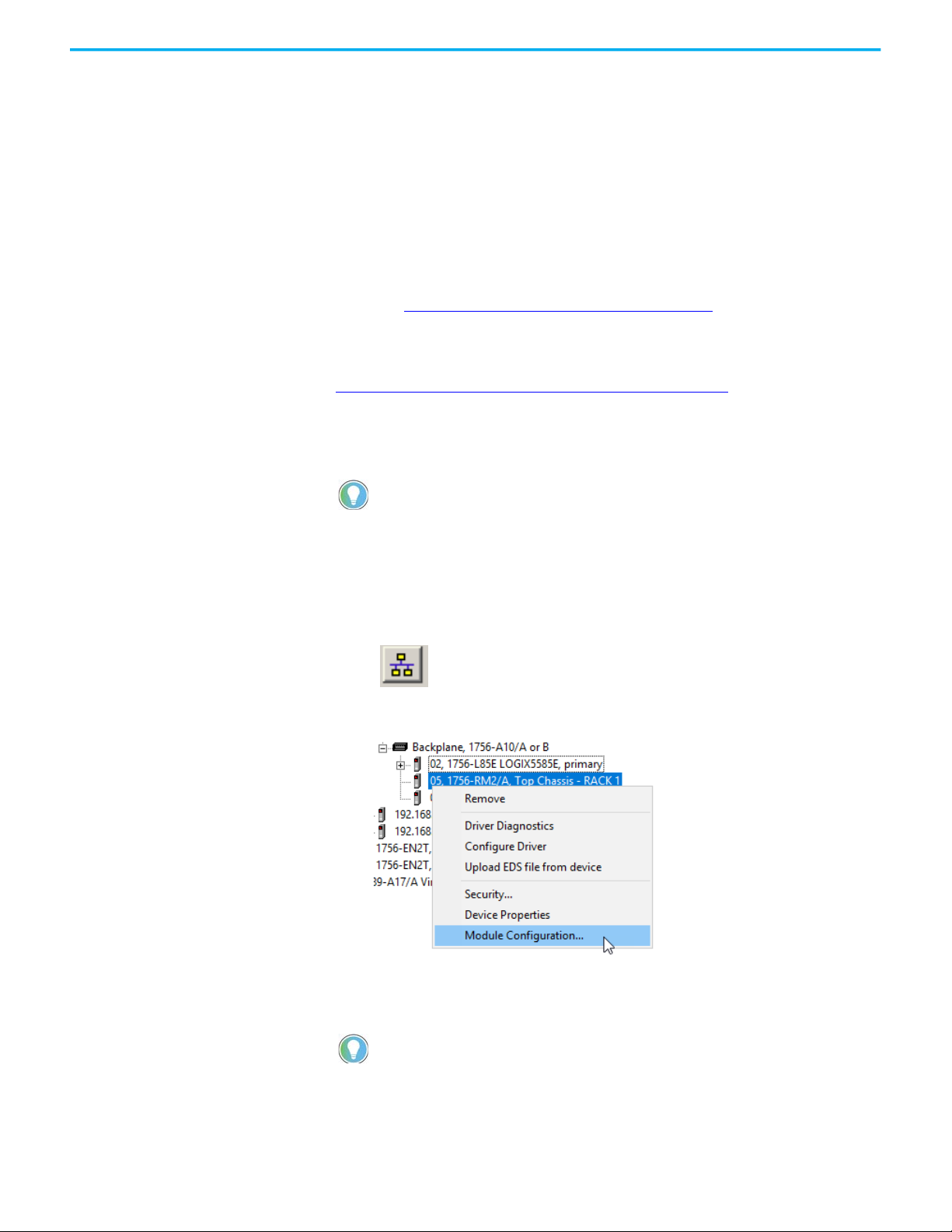
Chapter 4 Configure the Redundancy Modules
Identify the RMCT Version
You must use a version of the RMCT that is compatible with your redundancy
module firmware.
The redundancy module firmware reports back to the Redundancy Module
Configuration Tool (RMCT) as to which version of the RMCT is compatible. If
there is an incompatibility, the RMCT shows only the Module Info tab and
indicates the version that the firmware is compatible with.
For more information on the RMCT compatibility, see Knowledgebase
Technote Redundancy Module Configuration Tool (RMCT)
The Redundancy Module Configuration Tool (RMCT) is included in the
redundancy bundle download, and is not available for separate download. See
Download the Redundancy Firmware Bundle
on page 22.
Complete these steps to check or verify the version of the Redundancy Module
Configuration Tool (RMCT) that you have installed.
The RMCT launches at the version that is compatible with the ControlLogix® 5580
redundancy module firmware that is installed.
If you have not updated your ControlLogix 5580 redundancy module firmware
after upgrading your RMCT version, the RMCT version that is indicated can differ
from the version you updated to. You can also check the RMCT version that you
have installed by using Add or Remove Programs in the Control Panel.
1. Launch RSLinx Classic software.
2. Click the RSWho icon.
.
3. Right-click your redundancy module and choose Module Configuration.
The Module Configuration dialog box opens.
If you cannot see the Module Configuration option in the list, then the compatible
version of the RMCT is not installed.
42 Rockwell Automation Publication 1756-UM015B-EN-P - February 2021
Page 43
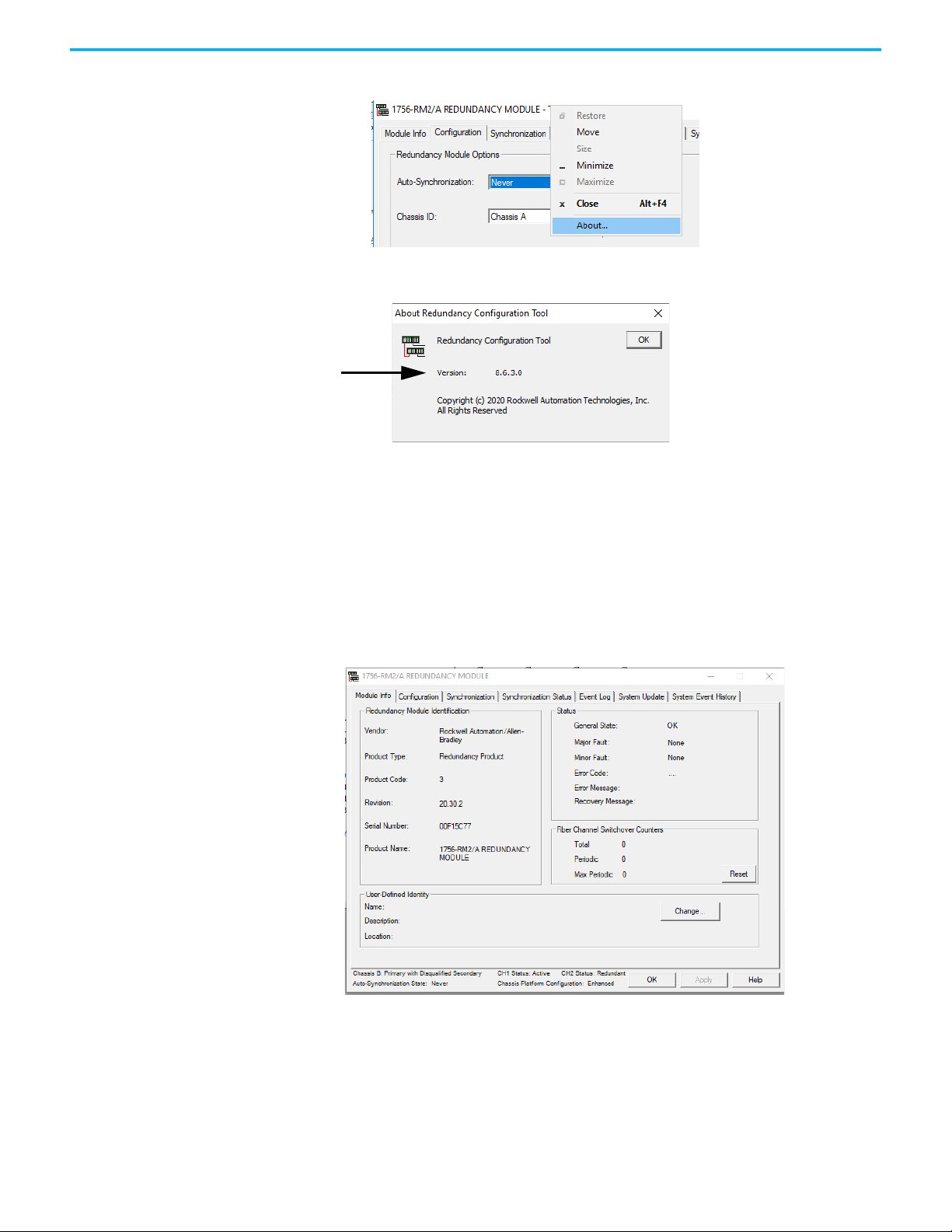
Chapter 4 Configure the Redundancy Modules
4. Right-click the title bar and choose About.
The About dialog box opens and indicates the RMCT version.
This should show the version you need based on your bundle or higher.
The RMCT always shows the latest version installed, and later versions
are backwards compatible with earlier versions.
Module Info Tab The Module Info tab of the RMCT provides a general overview of the
identification and status information of the redundancy module. This status
information is updated approximately once every two seconds.
Rockwell Automation Publication 1756-UM015B-EN-P - February 2021 43
Page 44

Chapter 4 Configure the Redundancy Modules
These parameters are indicated in the Module Info tab.
Module Info Tab - Parameters Indicated
Parameter Description
Vendor Name of the vendor of the redundancy module.
Product Type General product type of the redundancy module.
Product Code CIP™ product code for the redundancy module.
Revision Major and minor revision information for the redundancy module.
Redundancy Module Serial
Number
Product Name Predefined catalog name of the redundancy module.
General Status
Major Fault
Minor Fault
Error Code Error code that is related to the fault if one exists.
Error Message Text-based message that describes the error if a fault exists.
Recovery Message Text-based message that indicates the recovery from a fault.
Tot al
Periodic
Max Periodic Switchovers
CH1 Status
CH2 Status Fiber Channel 2 status. See CH1 Status
Chassis Platform
Configuration
(1) The Periodic counters can be used to identify a burst of switchovers that can take place due to intermittent
channel failures within a few seconds. The recorded time can be helpful to correlate the switchover occurrences
with any external failures that have occurred on the fiber cables.
Serial number of the redundancy module.
General state of the redundancy module. Possible values include Startup,
Load, Fault, and OK.
The major fault status of a redundancy module. When a major fault is
detected, the system does not provide redundancy support.
The minor fault status of a redundancy module. When a minor fault is
detected, the system continues to provide redundancy support.
Indicates the number of channel switchovers that have occurred from CH1
to CH2 and vice versa on the module since its last powerup. It is reset to 0
automatically by firmware on a power cycle.
Indicates the number of switchovers that have occurred between CH1 and
CH2 over the last 10-second interval. The counter is constantly updated to
reflect the value that is recorded at every 10-second interval. The counter
is automatically reset to 0 on a power cycle.
The maximum number that is recorded in the Periodic counter. The time of
the update is recorded every time that the counter is updated. The counter
is automatically reset to 0 on a power cycle and can also be reset by
clicking the Reset button.
Fiber Channel 1 status.
The status shows the operating condition of the respective fiber channels
in terms of one of the following values:
• Unknown - Operating state is not yet determined
• Active - Channel is operating normally as the ACTIVE channel
• Redundant - Channel is operating normally as the REDUNDANT channel
• Link Down - Channel is disconnected. Causes can be: the cable is
disconnected/broken/damaged; signal is attenuated, connector is loose,
the partner 1756-RM2 module is power down or in a major fault state
• No SFP - No transceiver was detected, it has failed, it is loosely
connected, it is not installed
• SFP !Cpt - Transceiver is not a Rockwell Automation supported unit
• SFP Fail - Transceiver is in a failed state
Indicates configuration.
(1)
on page 44.
In addition, you can click Change to edit the User-defined Identity parameters
to meet your application needs.
44 Rockwell Automation Publication 1756-UM015B-EN-P - February 2021
Page 45

Chapter 4 Configure the Redundancy Modules
Configuration Tab Use the Configuration tab to set redundancy options and the internal clock of
the redundancy module. After you modify a parameter, the Apply Workstation
Time button becomes active.
Auto-synchronization
The first parameter in the Configuration tab is the Auto-Synchronization
parameter. The value that you chose for this parameter determines a
significant part of your redundant system behavior.
Rockwell Automation suggests setting Auto-Synchronization to Always.
Verify that your Auto-Synchronization parameter is at the proper value before you
modify your redundant system. This verification helps prevent system errors.
For example, if you are upgrading your redundant system firmware, verify that this
parameter is set to Never or Conditional before disqualifying your secondary
chassis. If this parameter is Always, you cannot properly disqualify your chassis
and conduct the update.
Use the following table to determine the Auto-Synchronization setting that
best suits your application.
If you use this parameter This synchronization behavior results
The system remains in the same state, that is, either synchronized or disqualified, until one of these events takes place:
Never
Always
Conditional
• A command is issued from the RMCT to either synchronize or disqualify.
• The controller commands synchronization or disqualification by using a MSG instruction. For this action to occur, Enable User
Program Control must be checked.
• A fault on the primary causes a switchover.
The system automatically synchronizes regularly.
If you attempt to disqualify the system by using the Disqualify Secondary command in the RMCT, the resulting disqualification is
temporary as the system automatically qualifies and synchronizes again.
If the controller program disqualifies the system, the resulting disqualification is also temporary.
The system behavior with this setting is dependent on the Auto-Synchronization state of your system, found in the lower left portion
of the RMCT window after setting the Auto-Synchronization parameter to Conditional:
• If your Auto-Synchronization parameter is set to Conditional and your Auto-Synchronization state is 'Conditional, Enabled', then the
system continually attempts to synchronize.
• If your Auto-Synchronization parameter is set to Conditional and your Auto-Synchronization state is 'Conditional, Disabled', then the
system does not automatically attempt to synchronize.
To change from 'Conditional, Enabled' to 'Conditional, Disabled', click Disqualify Secondary on the Synchronization tab.
To change from 'Conditional, Disabled' to 'Conditional, Enabled', click Synchronize Secondary on the Synchronization tab.
Rockwell Automation Publication 1756-UM015B-EN-P - February 2021 45
Page 46

Chapter 4 Configure the Redundancy Modules
Chassis ID
The chassis ID parameter is used to assign a generic label to the chassis that
house the redundancy modules. The available chassis labels are Chassis A and
Chassis B.
If you change the chassis label in the RMCT of the primary redundancy
module, the secondary module and chassis are automatically assigned the
other chassis label.
The chassis label that is assigned to the module remains associated with the
same physical chassis, regardless of its primary or secondary control
designation.
Enable User Program Control
Check Enable User Program Control in the Configuration tab if you plan to use
MSG instructions in your controller program to initiate a switchover, change
the redundancy module time, or synchronize.
If you leave Enable User Program Control unchecked, the redundancy modules
do not accept any commands from the controller.
Redundancy Module Date and Time
The Redundancy Module Date and Time parameters can be applied separate
from the Redundancy Module Options parameters. The time that is specified
with these parameters is the time that the event logs reference when a
redundant system event occurs.
To change the redundancy module time settings, use the pull-down menu or
type your changes and then click Set to implement time changes. Or, to set the
time of the redundancy module to match that of the workstation, click Apply
Workstation Time.
IMPORTANT We recommend that you set the redundancy module date and time when
you commission a system. We also recommend that you periodically
check the date and time settings to make sure that they match the
settings of the controller.
If a power failure occurs on the redundant chassis, you must reset the
date and time information of the redundancy modules. The modules do
not retain those parameters when power is lost.
46 Rockwell Automation Publication 1756-UM015B-EN-P - February 2021
Page 47
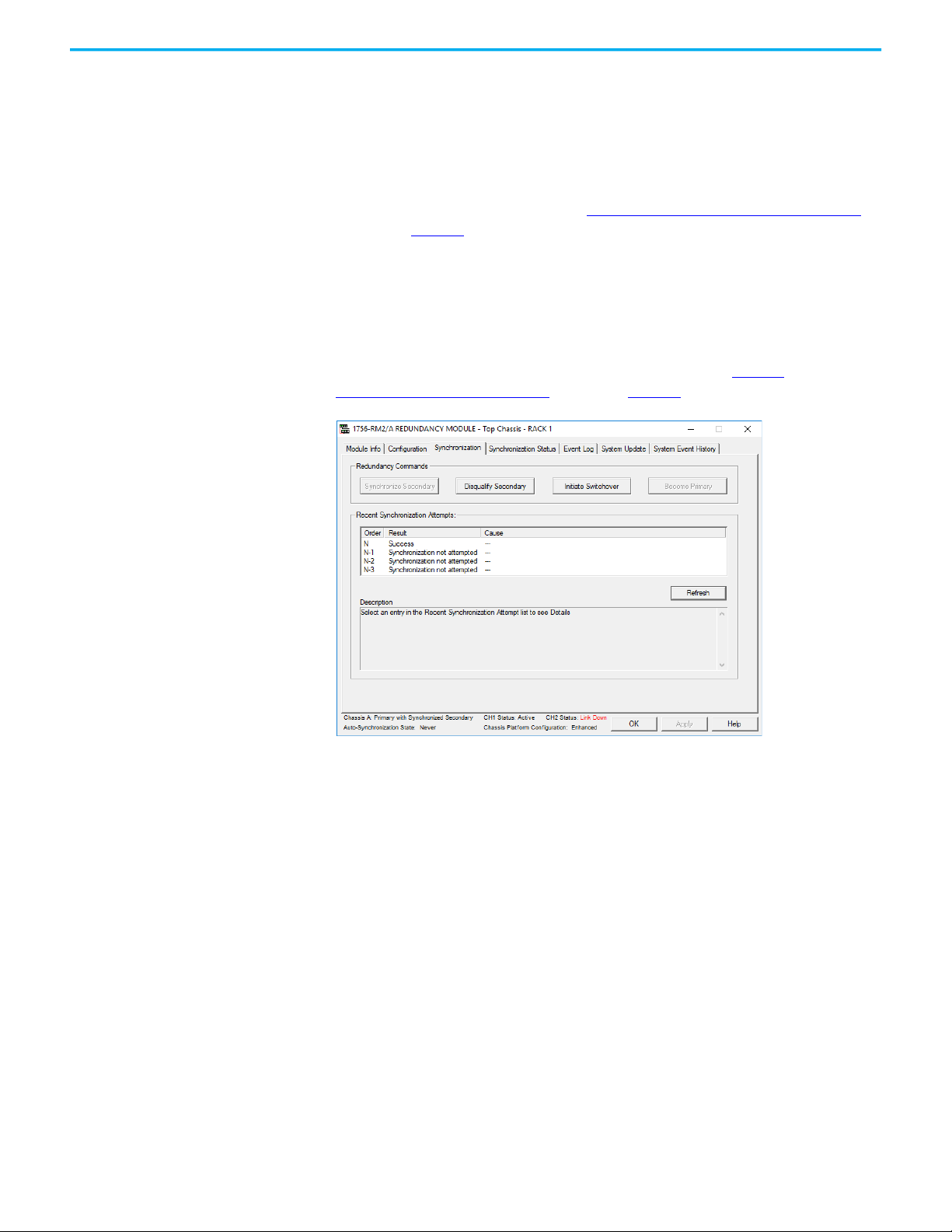
Chapter 4 Configure the Redundancy Modules
Synchronization Tab The Synchronization Tab has commands for these options:
• Change the synchronization state of the system (synchronize or
disqualify)
• Initiate a switchover
• Force the disqualified secondary to become the primary
The commands are described in the Commands in the Synchronization Tab
section on page 48
This tab also has information about the last four synchronization attempts in
the Recent Synchronization Attempts log. N or N-X identify synchronization
attempts in the log. If the redundant chassis fail to synchronize, a cause is
identified in the Recent Synchronization Attempts log.
The causes and their interpretations are described in the Recent
Synchronization Attempts Log section on page 48.
.
Rockwell Automation Publication 1756-UM015B-EN-P - February 2021 47
Page 48

Chapter 4 Configure the Redundancy Modules
ATTENTION:
• Disqualifying the secondary chassis makes it unable to assume control functions, that is, redundancy is lost.
• If you disqualify the secondary and a major fault occurs on the remaining primary, a switchover does not occur.
Command Description
This command forces the primary redundancy module to attempt synchronization with its partner. This command is available in specific
conditions:
• Available only when the chassis redundancy state is as follows:
Synchronize Secondary
• Primary with Disqualified Secondary
• Disqualified Secondary
• Unavailable (dimmed) in all other chassis states
Synchronization is asynchronous with the execution of this command. Successful execution of this command begins with synchronization,
which can take several minutes. Monitor the chassis status that is displayed at the bottom of the RMCT to determine when synchronization
has completed.
This command forces the primary redundancy module to disqualify its partner.
Commands in the Synchronization Tab
These sections explain each redundancy command and the system conditions
that are required for the command to be available.
Disqualify Secondary
Initiate Switchover
Become Primary
This command is available in specific conditions:
• Available only when the chassis redundancy state is as follows:
• Primary with Synchronized Secondary
• Synchronized Secondary
• Unavailable (dimmed) in all other chassis states
If you use the Disqualify Secondary command when the Auto-Synchronization parameter is set to Always, a synchronization attempt
occurs immediately after the secondary chassis becomes disqualified.
To keep the secondary disqualified after issuing a Disqualify Secondary command, set the Auto-Synchronization parameter to Conditional
or Never before disqualifying the secondary.
This command forces the system to initiate an immediate switchover from the primary chassis to the secondary chassis. This command
can be used when you upgrade redundancy system firmware or when you complete maintenance on one chassis of the redundant pair.
This command can also be used to perform a realistic test of your redundant system behavior by simulating a failure that is detected in
the primary control chassis.
This command is available in specific conditions:
• Available only when the chassis redundancy state is as follows:
• Primary with Synchronized Secondary
• Synchronized Secondary
• Unavailable (dimmed) in all other chassis states
This command forces a disqualified secondary system to become a primary system and is available in specific conditions:
• Available only when the chassis redundancy state is Secondary with No Primary.
• Unavailable (dimmed) in all other chassis states
Recent Synchronization Attempts Log
This table describes the possible result and causes of synchronization states.
Recent Synchronization Attempts Log - Result Interpretations
Result Result Interpretation
Undefined The result of the synchronization is unknown.
No attempt since last powerup
Success Full synchronization was successfully completed.
Abort
48 Rockwell Automation Publication 1756-UM015B-EN-P - February 2021
Synchronization has not been attempted since power was applied to
the module.
The synchronization attempt failed. See Table 3
information.
for further
Page 49

Chapter 4 Configure the Redundancy Modules
If the Synchronization Attempts log indicates that the Synchronization
attempt was aborted, use Table 3
to diagnose the cause.
Table 3 - Synchronization Interpretation
Cause Cause Interpretation
Undefined The cause of synchronization failure is unknown.
Module Pair Incompatible Synchronization was aborted because one or more module pairs are incompatible.
Module Configuration Error Synchronization was aborted because one of the modules is improperly configured.
Edit Session In Progress Synchronization was aborted because an edit or session is in progress.
Crossloading Failure An undetermined failure occurred during synchronization between redundancy modules.
Comm Disconnected The cable between the redundancy modules was disconnected.
Module Insertion Synchronization was aborted because a module was inserted into a chassis.
Module Removal Synchronization was aborted because a module was removed from a chassis.
Secondary Module Failed Synchronization was aborted because of a failure in the secondary module.
Incorrect Chassis State Synchronization was aborted due to an incorrect chassis state.
Comm Does Not Exist Synchronization could not be performed because the communication link between redundancy modules does not exist.
Non-redundant Compliant Module Exists Synchronization could not be performed because one or more non-redundancy modules are present in one of the chassis.
Sec Failed Module Exists A module in the secondary chassis has asserted the SYS_FAIL line, which indicates that it has faulted or failed.
Local Major Unrecoverable Fault Synchronization was aborted because of a local major unrecoverable fault.
Partner Has Major Fault Synchronization was aborted because the partner module has a major fault.
Sec SYS_FAIL_L Subsystem Failed The test of the SYS_FAIL line in the secondary chassis failed.
Sec RM Device Status = Comm Error Synchronization was aborted because the status of the secondary redundancy module indicates a communication error.
Sec RM Device Status = Major Recoverable
Fault
Sec RM Device Status = Major Unrecoverable
Fault
Incorrect Device State Synchronization was aborted because the device is in the wrong state.
Primary Module Failed Synchronization was aborted because of a failure in the primary module.
Primary Failed Module Exists A module in the primary chassis has asserted the SYS_FAIL line, which indicates that it has faulted or failed.
Auto-Sync Option
Module Qual Request
SYS_FAIL_L Deasserted Synchronization was aborted because one of the modules came out of a faulted or failed state.
Disqualify Command
Disqualify Request
Platform Configuration Identity Mismatch
Detected
Application Requires Enhanced Platform
ICPT Asserted A test line on the backplane is asserted.
Unicast Not Supported A unicast connection is configured in the redundant controller, and redundancy systems do not support Unicast.
PTP Configuration Error
Secured Module Mismatch A mismatch was detected betw
Synchronization was aborted because the status of the secondary redundancy module indicates a major recoverable fault.
Synchronization was aborted because the status of the secondary redundancy module indicates a major unrecoverable fault.
Synchronization was aborted because the Auto-Synchronization parameter of one of the redundancy modules was changed
during synchronization.
Synchronization was aborted because another synchronization request was received. The current synchronization has
stopped so that the new synchronization request can be serviced.
Synchronization was aborted because the redundancy module received a disqualify command from another device. The
originating device sends this command when it can no longer perform in the qualified state.
Synchronization was aborted because the redundancy module received a disqualify command from another device. The
originating device sends this command when it can no longer perform in the qualified state.
There are modules in the primary or secondary chassis that do not belong to the platform.
A redundant controller is running an application that contains a feature that is qualified to run only on an enhanced
redundant platform, for example, Alarms.
The PTP clock of a redundant controller is not synchronized or the partner controller pair is synchronized to another
Grandmaster.
een a primar
y and secondary secured module.
Contact Rockwell Automation technical support for help with troubleshooting
the cause listed in the table above.
Rockwell Automation Publication 1756-UM015B-EN-P - February 2021 49
Page 50

Chapter 4 Configure the Redundancy Modules
Synchronization State
Chassis Designation Module-partner Compatibility
Synchronization Status Tab The Synchronization Status tab provides a module-level view of these items:
• Synchronization state (for example, Synchronized or Disqualified)
• Chassis designation (Primary or Secondary)
• Module compatibility with its partner (for example, Full or Undefined)
Each module that is installed in the chassis is identified and information
regarding its partner and compatibility are provided.
50 Rockwell Automation Publication 1756-UM015B-EN-P - February 2021
Page 51

Chapter 4 Configure the Redundancy Modules
System Update Tab Use of the commands in the System Update tab lets you perform firmware
updates in the secondary chassis while the primary chassis remains in control.
Reference the lock and switchover logs in this tab for update information
when completing a firmware update.
ATTENTION: When performing firmware updates by using
commands in the System Update tab, redundancy is lost. In
the event of a fault on the operating primary chassis, the
system cannot switch control to the secondary chassis.
Rockwell Automation Publication 1756-UM015B-EN-P - February 2021 51
Page 52

Chapter 4 Configure the Redundancy Modules
System Update Commands
The three system update commands are available only when accessing a
primary redundancy module. These commands are not available when
accessing the secondary redundancy module.
While you are completing tasks to update the system by using the system update
commands, you cannot access these tabs in the RMCT:
• Configuration
•Synchronization
• Synchronization Status
If you attempt to access any of these tabs while the system is locked or is
completing a locked switchover, it results in an error dialog box.
Lock For Update
The Lock for Update command lets you synchronize a redundant chassis pair
under these conditions:
• The secondary redundancy module uses updated firmware and an
updated programming software application program version.
• The running primary redundancy module uses a previous firmware
revision and previous programming software application program
version.
The Lock for Update command is available only when all modules in the
primary chassis have no compatibility discrepancies. Before issuing the lock
command, complete these tasks:
• Set the Auto-Synchronization option in the Configuration tab to Never.
• Disqualify the secondary chassis by using the Disqualify Secondary
command in the Synchronization tab of the RMCT of the secondary
redundancy module.
• Update the primary and secondary redundancy modules to compatible
firmware revisions.
• Update all other modules in the secondary chassis to their intended
firmware revisions.
• Configure the controller project as required to accommodate the update
and replacement of modules if needed.
For details about how to complete those tasks, see Configure Redundant
Firmware on page 24.
52 Rockwell Automation Publication 1756-UM015B-EN-P - February 2021
Page 53
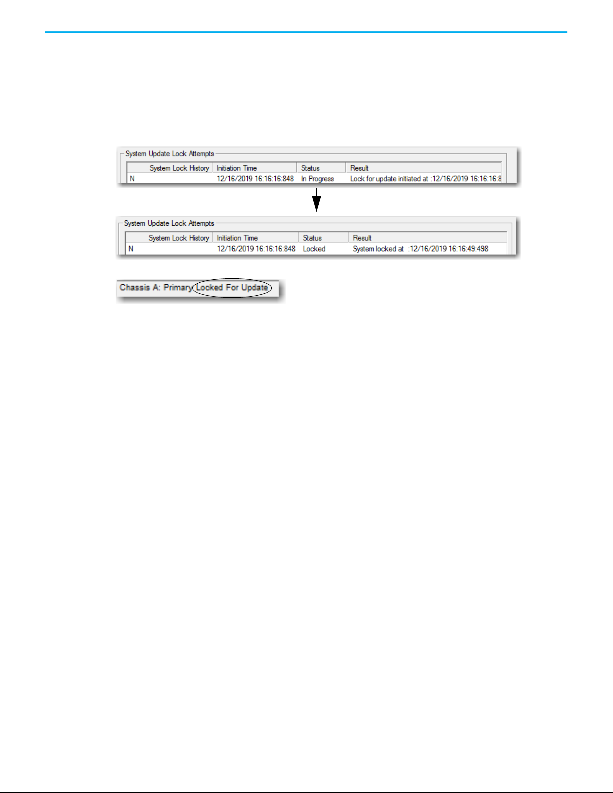
Chapter 4 Configure the Redundancy Modules
Lock initiated.
Lock complete.
Lock complete.
Click the Lock for Update command to initiate the locking process. The lock
can take several minutes to finish. Monitor the System Update Lock Attempts
log to determine when the lock is complete. In addition, the chassis status that
is shown at the bottom-left of the dialog box changes from Primary with
Disqualified Secondary to Primary Locked for Update.
Lock for Update Status Updates
Abort System Lock
The Abort System Lock command can be used to stop the system lock. It is
available as soon as a lock for update is initiated.
Click Abort System Lock to return the redundant chassis status to Primary
with Disqualified Secondary. This action also causes the system update to stop
and the program in the secondary controller to clear. If you click Abort System
Lock, you must download the program to the secondary controller before
reattempting a Lock for Update.
Initiate Locked Switchover
The Initiate Locked Switchover command is available only when the chassis
redundancy state is Primary with Locked Secondary. That is, the Initiate
Locked Switchover is available only after the lock for update is complete.
If you click Initiate Locked Switchover, your secondary chassis assumes
control and becomes the new primary. The old primary is now the new
secondary chassis and you can update the firmware of the modules in the new
secondary chassis.
Rockwell Automation Publication 1756-UM015B-EN-P - February 2021 53
Page 54

Chapter 4 Configure the Redundancy Modules
Chassis A
Chassis A
Chassis B
Chassis B
Primary
Primary
Secondary
Secondary
Illustration of Switchover
CH2 CH1 OK
CH2 CH1 OK
CH2 CH1 OK
CH2 CH1 OK
The difference between a locked switchover and a normal switchover is that
you initiate the locked switchover. You or a fault in the primary chassis initiate
a normal switchover.
System Update Lock Attempts
The System Update Lock Attempts log is where attempts to lock the system are
logged. This log displays the last four lock attempts and provides this
information specific to each attempt:
• Time and date
• Status (for example, Locked or Abort)
• Result (for example, System Locked or Invalid Response Received)
The status indicated in the System Update Lock Attempts log can be any one of
the states that are listed in Table 4
Table 4 - System Update Lock Attempts Log Statuses
Status Interpretation
Not Attempted A system lock has not been attempted since the last powerup.
In Progress A lock is in progress.
Locked The lock was successfully completed.
Abort The lock attempt failed. The reason for the failure is indicated in a Result field.
.
54 Rockwell Automation Publication 1756-UM015B-EN-P - February 2021
Page 55

Chapter 4 Configure the Redundancy Modules
If your status is indicated as Abort, one of these conditions can exist:
• An error occurred while communicating with the partner redundancy
module.
• A module in the secondary chassis does not have a partner in the primary
chassis.
• A module pair is incompatible.
• The SysFail test was unsuccessful in the primary redundancy module.
• A Major Recoverable Fault occurred in primary redundancy module.
• A Major NonRecoverable Fault occurred in primary redundancy module.
• A module was inserted into the chassis.
• A module was removed from the chassis.
• A failed module exists in the secondary chassis.
• A failed module exists in the primary chassis.
• An Abort System Update command was received.
• Invalid response was received from a module.
• A module rejected the state change.
• A platform mismatch was detected.
For more information on Lock for Update Failures, see Knowledgebase
Technote Lock for Update Fails
.
Locked Switchover Attempts
The Locked Switchover Attempts log provides information about the status of
the last four locked switchover attempts. This log includes this information
about each attempt:
• Time and date
• Status
•Result
The status indicated in the Locked Switchover Attempts log can be any one of
the states that are listed in Table 5
Table 5 - Locked Switchover Event Log Statuses
Status Description
Not Attempted A locked switchover has not been attempted since the last powerup.
In Progress A locked switchover is in progress.
Success A locked switchover was successfully completed.
Abort
The locked switchover attempt failed. The cause of the failure is indicated in a Result
field.
If a locked switchover is aborted, it can be because of the following:
• A module declined a locked switchover readiness request.
• An invalid response was received from the locked switchover readiness
request.
• After an initiate switchover prompt, a module rejected the command.
• After an initiate switchover prompt, a module replied with an invalid
response.
.
Rockwell Automation Publication 1756-UM015B-EN-P - February 2021 55
Page 56

Chapter 4 Configure the Redundancy Modules
Notes:
56 Rockwell Automation Publication 1756-UM015B-EN-P - February 2021
Page 57

Configure the Redundant Controller
Top ic Pa g e
Configure the Redundant Controller 57
Enable Time Synchronization 59
Crossloads, Synchronization, and Switchovers 61
Crossloads and Scan Time 65
Set the Task Watchdog 67
Chapter 5
Configure the Redundant
Controller
Both controllers in the ControlLogix® redundancy system operate by using the
same program. You do not need to create a project for each controller in the
redundant system.
IMPORTANT
To configure your controllers to operate in a redundant system, complete these
steps.
1. Open or create a project for your redundant controller.
2. Access the Controller Properties dialog box for the controller.
When programming your redundancy system, you should only interface
with the controller in the primary rack unless a specific workflow
dictates that the controller in the secondary rack should be the target
of modification
3. Click the Redundancy tab, and check the Redundancy Enabled checkbox.
Rockwell Automation Publication 1756-UM015B-EN-P - February 2021 57
Page 58
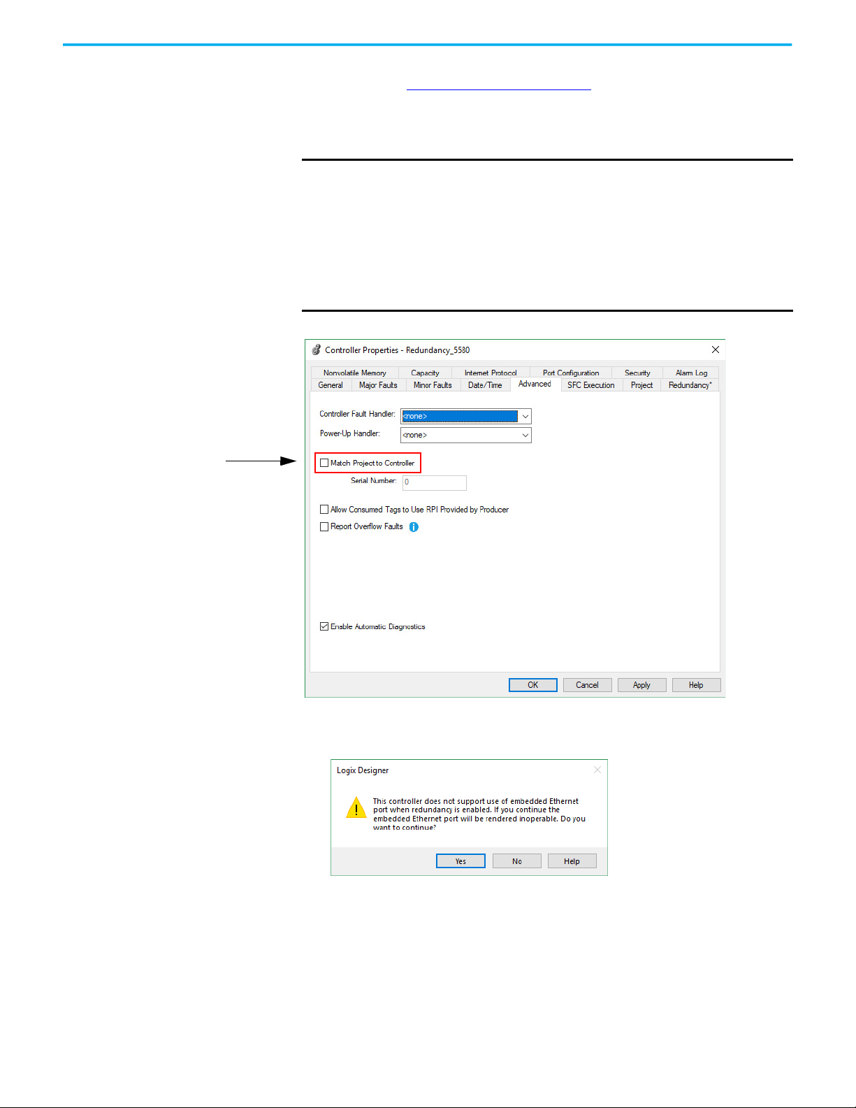
Chapter 5 Configure the Redundant Controller
Verify that this option is
not checked.
4. If you are going to complete edits to your redundant controller while
online, see Plan for Test Edits
on page 95 for information about the
parameters available in the Advanced settings.
5. Click the Advanced tab, and verify that Match Project to Controller is
unchecked.
IMPORTANT
Do not use Match Project to Controller property with redundant
controllers.
If you use the Match Project to Controller property available in the
Advanced tab of the Controller Properties dialog box, you cannot go
online with, download to, or upload from the new primary controller
after a switchover. This is because the serial number of the new
primary controller is not the same as the serial number of the old
primary controller and the project cannot be matched to the newly
switched to controller.
6. Click Apply.
7. On the Logix Designer popup, click Yes.
58 Rockwell Automation Publication 1756-UM015B-EN-P - February 2021
Page 59

Chapter 5 Configure the Redundant Controller
Verify that this option is
checked.
The Logix Designer application removes the front Ethernet port from the
I/O configuration.
8. On the Controller Properties dialog box, Click OK.
You have completed the minimum configuration that is required for your
redundant controllers.
Enable Time Synchronization
Time synchronization is not required for redundancy to function. If your
application requires Time synchronization, then follow these steps.
1. At the Date/Time tab in Controller Properties, make sure that Enable
Time Synchronization is checked.
2. Click Apply.
3. Click OK.
4. Click Yes, on the Logix Designer popup.
5. Access the Module Properties dialog box for the Ethernet module.
Rockwell Automation Publication 1756-UM015B-EN-P - February 2021 59
Page 60
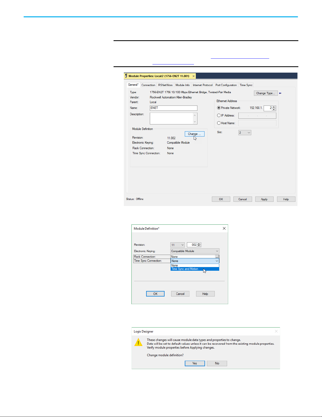
Chapter 5 Configure the Redundant Controller
6. At the General tab of the Module Properties dialog box of the Ethernet
module, click Change.
IMPORTANT
At least one Ethernet module requires this configuration if time
synchronization is enabled on the controller. For more information, see
the Knowledgebase Technote Troubleshooting ControlLogix
Redundancy Systems.
7. From the Time Sync connection pull-down menu, select Time Sync and
Motion.
.
8. Click OK to close the dialog box.
9. At the warning dialog box, click Yes.
10. Click Apply.
11. Click OK to close the Module Properties dialog box.
60 Rockwell Automation Publication 1756-UM015B-EN-P - February 2021
Page 61
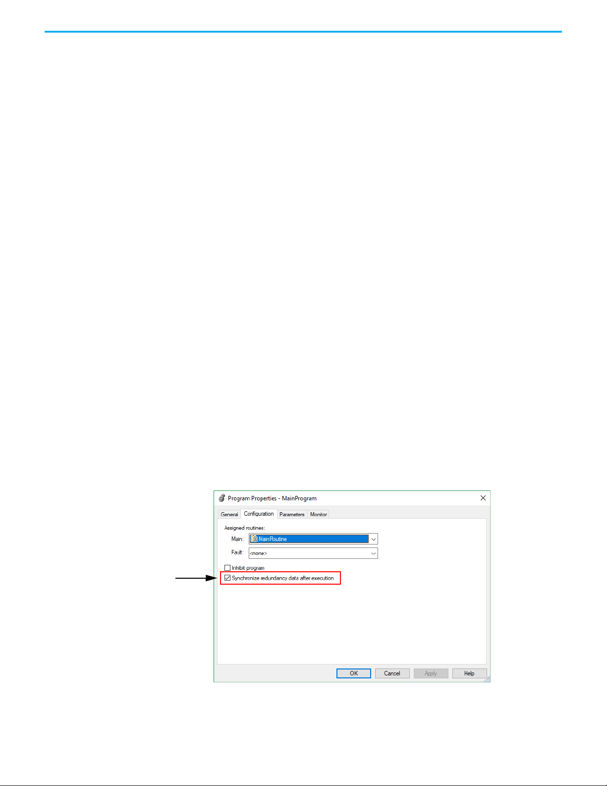
Chapter 5 Configure the Redundant Controller
Use this setting to change crossload and
synchronization points.
Crossloads, Synchronization, and Switchovers
Crossloading or synchronization points are points where the primary
controller transfers data to the secondary controller. Crossload and
synchronization points keep the secondary controller ready to assume control
in the event of a fault on the primary.
Before you begin programming your redundant controller, be aware of the
impact of crossloads and synchronization on the execution of a program after
a switchover. If you understand these concepts, it helps you to create
programming that best meets the needs for your redundant application.
Continue reading the sections that follow for explanations of crossloads and
synchronization and their relationship to switchovers and program execution.
Changing Crossload and Synchronization Settings
In the redundancy system, crossload and synchronization points for programs
within the Studio 5000 Logix Designer® project are configurable. You can limit
which programs data crossloading and synchronization follow. In many
applications, changes to this setting can reduce the overall impact to the task
scan time by reducing the number of times data is crossloaded.
If you reduce the number of crossload and synchronization points, the
switchover time becomes longer. This increase in switchover time is because
more programs need to be rescanned after the switchover.
Synchronization is performed at the end of the last program in the program
list of the task, regardless of the Synchronize Data after Execution setting for
the program.
To change the synchronization setting of a program, open the Program
Properties dialog box of the program and check or uncheck Synchronize
redundancy data after execution.
Rockwell Automation Publication 1756-UM015B-EN-P - February 2021 61
Page 62

Chapter 5 Configure the Redundant Controller
Default Crossload and Synchronization Settings
The default setting for a program in a redundant project is for a crossload to
occur at the end of each program execution. However, for an equipment
phase, the default is that the crossload does not execute at the end of the phase.
Before you change the default crossload and synchronization settings, read the
sections that follow so you have a complete understanding of the implications.
For information about how to change the point in a task where a crossload
occurs, see Changing Crossload and Synchronization Settings
on page 61.
Recommended Task Types
To make synchronization, crossloads, and HMI updates as fast as possible,
avoid using a continuous task. Instead, the best practice is to use periodic
tasks. The fewer the number of periodic tasks used, the better the
performance.
IMPORTANT
Only the single highest-priority periodic task can ensure bumpless output
switching on switchover. The sections that follow explain the impact of
crossloads and synchronization after a switchover based on the task structure
you use.
We suggest avoiding a continuous task for applications that are
larger and/or have heavy communication, For more information
see Programming Best Practices
on page 71.
Continuous Task After Switchover
After a switchover occurs within a controller project that contains only a
continuous task, the new primary begins executing at the last crossload and
synchronization point. Depending on your crossload and synchronization
setting, the program that the new primary controller begins with can be
the following:
• The program that the switchover interrupted
• The program that immediately follows the last crossload and
synchronization point
Continuous Task with Crossloads at Each Program End
This diagram demonstrates how programs set to crossload and synchronize at
each program-end are executed after a switchover. As is shown, the new
primary controller begins executing at the beginning of the program that the
switchover interrupted. This process is the switchover execution that occurs if
you use the default crossload and synchronization setting for a program.
62 Rockwell Automation Publication 1756-UM015B-EN-P - February 2021
Page 63
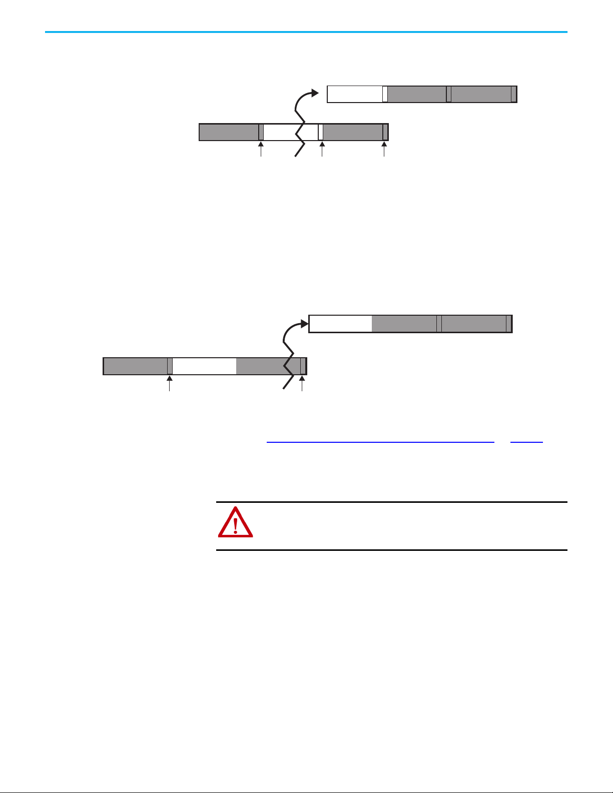
Chapter 5 Configure the Redundant Controller
Primary Controller
New Primary Controller
Program 2
Program 3
Program 1
Program 1
Program 2
Program 3
Switchover
Crosslo
Crossload
Crossload
Crossload
Primary Controller
New Primary Controller
Program 2
Program 3
Program 1
Program 1
Program 2
Program 3
Switchover
Crossload
Crossload
Figure 5 - Program Execution After a Switchover (Crossload After each Program)
Continuous Task with Varying Crossloads at Program End
This diagram demonstrates how programs set to crossload and synchronize at
various intervals are executed after a switchover. As is shown, the new primary
controller begins executing the program that follows the last crossload and
synchronization point.
Figure 6 - Program Execution After a Switchover (no Crossload After each Program)
For information about how to change the point in a task where a crossload
occurs, see Changing Crossload and Synchronization Settings
on page 61.
Multiple Periodic Tasks
ATTENTION: If you use multiple periodic tasks, program all crucial
outputs within the highest-priority task. Failure to program outputs in
the highest-priority task can result in outputs changing state if a
switchover occurs.
In a project where multiple periodic tasks are used, the point where program
execution begins after a switchover depends on the following:
• Crossload and synchronization settings
• Task priority settings
As with the continuous task, the controller begins executing at the program
that follows the last crossload and synchronization point.
In addition, a higher priority task can interrupt a lower priority task. If a
switchover occurs during or just after the higher priority task executes and the
lower priority task has not been completed, then the lower priority task and
programs are executed from the point at which the last crossload occurred.
Rockwell Automation Publication 1756-UM015B-EN-P - February 2021 63
Page 64

Chapter 5 Configure the Redundant Controller
Crossload
Crossload
Task - Priority 2
Task - Priority 1
Task - Priority 2
Task - Priority 1
Higher-priority
Task Interrupts
Lower-priority
Task Resumes
Program 3
Program 3
Program 2
Program 1
Program 3Program 2Program 1
Program 1
Progra
am 2
Crossload
Primary New Primary
Task - Priority 1
Program 2
Task - Priority 2
Task - Priority 2
Task - Priority 1
Task - Priority 2
Program 3
Program 3
Program 1
Progra m 2
Program 2
Program 3
Program 2
Program 3
Program 1
Crossload
Crossload
Switchover
Crossload
Higher-priority
Task Interrupts
Lower-priority
Task Resumes
Crossload
Crossload
Task - Priority 2
Task - Priority 2
Switchover
This diagram demonstrates how tasks at different priorities execute if a
switchover occurs while a lower priority task is executing. The crossload and
synchronization points in this example are set to occur only at the end of the
last program within the tasks. The points are not set to occur at the end of each
program.
Figure 7 - Normal Periodic Task Execution (no switchover)
The following diagram shows a lower priority task that has not been completed
and a switchover occurs. The lower priority task and programs are executed
from the beginning of the program where the switchover occurred. This result
is because the program uses the default configuration and crossloads and
synchronization points occur at the end of each program.
Figure 8 - Periodic Task Execution After Switchover When Configured to Crossload After Programs
The following diagram shows a lower priority task that has not been completed
and a switchover occurs. The lower priority task and programs are executed
from the beginning and not at the program where the switchover occurred.
This result is because the crossloads and synchronization points were not
configured to occur at the end of each program.
64 Rockwell Automation Publication 1756-UM015B-EN-P - February 2021
Page 65
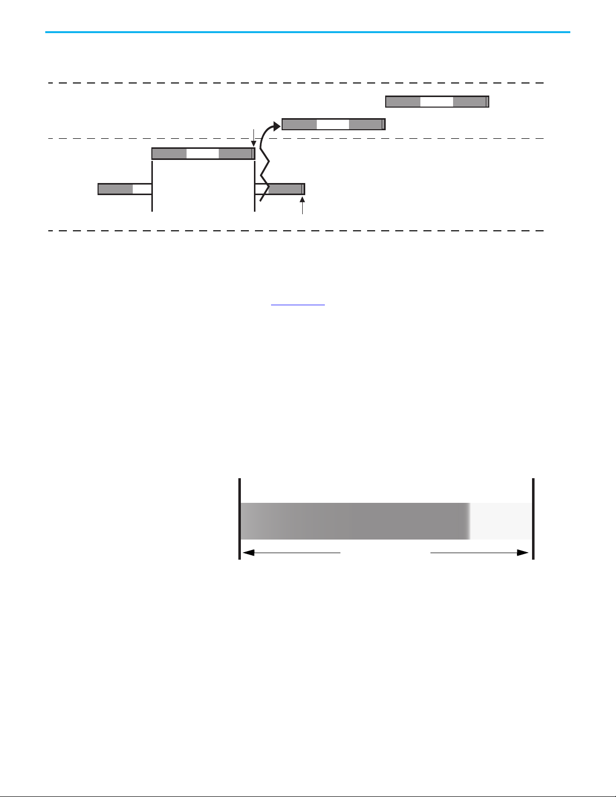
Chapter 5 Configure the Redundant Controller
Primary New Primary
Program 2
Program 3
Crossload
Higher-priority Task Interrupts
Lower-priority
Task Resumes
Task - Priority 2
Switchover
Task - Priority 2
Task - Priority 2
Program 1
Crossload
Program 2
Program 3
Program 1
Program 2
Program 3
Program 1
Progr
Program 1
am 2
Program 3
Task - Priority 1
Task - Priority 1
Program Scan Time
Execution of Program Crossload
Figure 9 - Periodic Task Execution After Switchover When Configured Not to Crossload After
Programs
For more information about programs and tasks with controllers, see the
Logix 5000 Controllers Tasks, Programs, and Routines Programming Manual,
publication 1756-PM005
.
Crossloads and Scan Time It is important to plan for controller crossloads because the length of the
crossloads affects the scan time of your program. A crossload is a transfer of
data from the primary controller to the secondary controller. The crossload can
occur at the end of each program or at the end of the last program in a task.
The scan time of your program or phase is a total of the program execution
time and the crossload time. The following diagram demonstrates this
concept.
Figure 10 - Crossload and Scan Time
Estimate the Crossload Time
The amount of time that is required for a crossload is primarily dependent
upon the amount of data being crossloaded. During a crossload, any tag that
has been written to during the program execution is crossloaded, even if the
tag value has not changed.
The crossload requires time to transfer tag value changes. The crossload also
requires a small amount of overhead time to communicate information about
the program being executed.
Rockwell Automation Publication 1756-UM015B-EN-P - February 2021 65
Page 66

Chapter 5 Configure the Redundant Controller
Redundancy Object Attributes for Crossload Times
Before you complete calculations to estimate the crossload time, you must use
a Get System Value (GSV) instruction to read certain attributes of the
redundancy object. These attributes are data transfer sizes that are measured
in DINTs (4-byte words) and are used to calculate the estimated crossload
time.
To get these attributes, you do not need to have the secondary chassis installed or
operating. If you do not have the secondary chassis operating, the attribute values
read indicate what data sizes would be transferred if the secondary chassis was
in use.
This table indicates the two attributes that you can choose to get specific to the
crossload data transfer size. Get the attribute value that meets your application
requirements.
If you need the Then get this attribute value
Data size of the last data that is transferred during the last crossload LastDataTransferSize
Data size of the largest crossload of data MaxDataTransferSize
The LastDataTransferSize attribute refers to the transfer size of the previous
crossload and synchronization point, which occurred before the program that
contains the GSV instruction.
If you must measure the crossloaded data from the last program in the
program list of the task, add an additional program at the end of the task that
acquires the LastDataTransferSize value from the program that was formerly
at the end of the task.
IMPORTANT
MaxDataTransferSize obtains maximum data transferred from only the
task the GSV executes within. This includes program-scoped data in
addition to controller-scoped data that was changed after the previous
sync point.
66 Rockwell Automation Publication 1756-UM015B-EN-P - February 2021
Page 67

Chapter 5 Configure the Redundant Controller
Equation for Estimating Crossload Times
Use this equation to estimate the crossload time of your controllers for each
program after you have either of the following:
• The size of the last data transfer
• The maximum size of data that is transferred
The following equations apply when a ControlLogix 5580 controller is paired
with a redundancy module in both chassis in a redundancy system.
Crossload Times for ControlLogix 5580 Controllers
Controller
ControlLogix 5580 1756-RM2 Crossload time per sync point (ms) = (DINTs * 0.000360) + 0.44 ms
Paired with
Redundancy Module
Crossload Time
A sync point is a mechanism that the primary controller uses to keep the
secondary controller in sync. By default, at the end of each program scan, the
primary controller sends the secondary controller the sync point and the
secondary controller responds by moving its execution pointer to match the
primary controller.
The default for phases is not to send a sync point.
Set the Task Watchdog Watchdog times set for tasks in redundancy applications must be larger than
watchdog times set for tasks in non-redundancy applications because more
time is required to conduct crossloads and synchronization.
IMPORTANT
An increase in the required watchdog time is also a result of the way programs
are executed in the event of a switchover. A program or programs can be
executed a second time after switchover. This action depends on when in the
task or program the switchover occurs and where in the task crossload and
synchronization occurs.
A continuous task should not have a watchdog time longer than 10
seconds in order to prevent issues with online edits or RSU Locked
Switchovers.
If a program is executed a second time, the length of time that is required for
the program scan is increased. However, the watchdog timer is not reset and
continues to countdown from the beginning of the task that the old primary
controller started. Therefore, the watchdog timer must be configured to
account for the potential of additional program scans.
Rockwell Automation Publication 1756-UM015B-EN-P - February 2021 67
Page 68

Chapter 5 Configure the Redundant Controller
Crossload
Crossload
Crossload
Switchover
Program 1
Program 2
Program 3
Program 2
Program 3
Task
Task Watchdog
Crossload
Crossload
Crossload
Switchover
Program 1
Program 2
Program 3
Program 2
Program 3
Task
Task Watchdog
Figure 11 - Watchdog Configured for Redundancy Switchover
In the event of a watchdog timeout, a major fault (type 6, code 1) results. If this
fault occurs after a switchover, the control system fails-to-safe or to the
configured hold state.
Figure 12 - Watchdog Not Configured for Redundancy Switchover
68 Rockwell Automation Publication 1756-UM015B-EN-P - February 2021
Page 69

Chapter 5 Configure the Redundant Controller
Minimum Value for the Watchdog Time
To set Watchdog time for your ControlLogix 5580 controller, use this table to
determine which equation to use to calculate the time for each task.
If Then use this equation
Using Ethernet I/O ms (2 * maximum _scan_time) + 100
The maximum_scan_time is the maximum scan time for the entire task when
the secondary controller is synchronized.
To set the initial task tuning of the ControlLogix 5580 controller, follow these
steps.
IMPORTANT
This process works only when there is no Continuous task that is
configured in the Logix application.
1. Monitor the Max Scan Time for each task while the redundant chassis
pair is synchronized.
2. Set the Watchdog times for each task to three times the Max Scan Time.
3. To configure each Task Period, use the L_CPU Add-on-Instruction.
(a)
a. Adjust the Task periods of each so that the maximum scan time is less
than 80% of the task period rate.
b. Adjust the Task periods so that the Logix CPU % utilization is never
above 80%.
c. While performing these tests, the HMI and any other external systems
must be connected to the Logix controller.
IMPORTANT
Verify that there are no task overlaps.
(a) See the Knowledgebase Technote L_CPU AOI Download
Rockwell Automation Publication 1756-UM015B-EN-P - February 2021 69
Page 70

Chapter 5 Configure the Redundant Controller
Notes:
70 Rockwell Automation Publication 1756-UM015B-EN-P - February 2021
Page 71

Programming Best Practices
Top ic Pa g e
Program to Minimize Scan Times 71
Program to Maintain Data Integrity 76
Optimize Tasks 80
Programming Considerations 81
Conduct a Test Switchover 84
Program Logic to Run After a Switchover 86
Use Messages for Redundancy Commands 87
Download the Project 90
Store a Redundancy Project to Nonvolatile Memory 91
Online Edits 94
Chapter 6
Program to Minimize Scan Times
There are several aspects of your program that must be as efficient as possible
to facilitate the fastest possible switchover because total program scan time
impacts system switchover time. The sections that follow describe methods to
make your program more efficient to minimize your program scan time.
These methods make your program more efficient and minimize program
scan times:
• Minimize the Number of Programs
• Manage Tags for Efficient Crossloads
• Use Concise Programming
Rockwell Automation Publication 1756-UM015B-EN-P - February 2021 71
Page 72

Chapter 6 Programming Best Practices
Figure 13 - Use of Multiple Routines (preferred) Figure 13 - Use of Multiple Programs (not preferred)
Minimize the Number of Programs
When programming a redundant controller, use the fewest programs possible.
Use of the fewest programs possible is especially important if you plan to
crossload data and synchronize the controllers after the execution of each
program.
If you must crossload data at the end of each program, make these
programming considerations to minimize the crossload impact on the
program scan time:
• Use only one or a few programs.
• Divide each program into the number of routines that is appropriate for
your application. A routine does not cause a crossload or increase the
scan time.
• Use the main routine of each program to call the other routines of the
program.
• If you want to use multiple tasks for different scan periods, use only one
program in each task.
72 Rockwell Automation Publication 1756-UM015B-EN-P - February 2021
Page 73
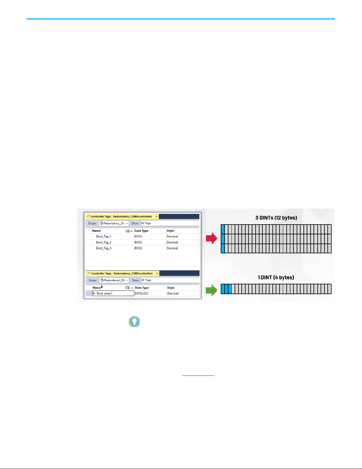
Chapter 6 Programming Best Practices
Manage Tags for Efficient Crossloads
Manage your data tags as the following sections recommend to program for
more efficient crossloads of data and reduce the amount of time that is
required for a crossload to execute.
Delete Unused Tags
If you delete unused tags, it reduces the size of the tag database. A smaller
database takes less time to crossload.
Use Arrays and User-defined Data Types
If you use arrays and user-defined data types, the tags use smaller 4-byte
(32-bit) words for all data in the type or array. If you create an individual tag,
the controller reserves 4 bytes (32 bits) of memory even if the tag uses only 1 bit.
Arrays and user-defined data types help conserve the most memory with BOOL
tags. However, we also recommend that you use them for your SINT, INT,
DINT, REAL, COUNTER, and TIMER tags.
Figure 14 - Example Savings with the Use of an Array
If you have already created individual tags and programming that uses those tags,
consider changing the individual tags to alias tags that reference the elements in
an array.
If you choose this method, your programming can still reference the individual tag
names, but the crossload transfers the base array.
For more information about how to work with arrays, user-defined data types,
and alias tags, see the Logix 5000 Controllers I/O and Tag Data Programming
Manual, publication 1756-PM004
.
Rockwell Automation Publication 1756-UM015B-EN-P - February 2021 73
Page 74
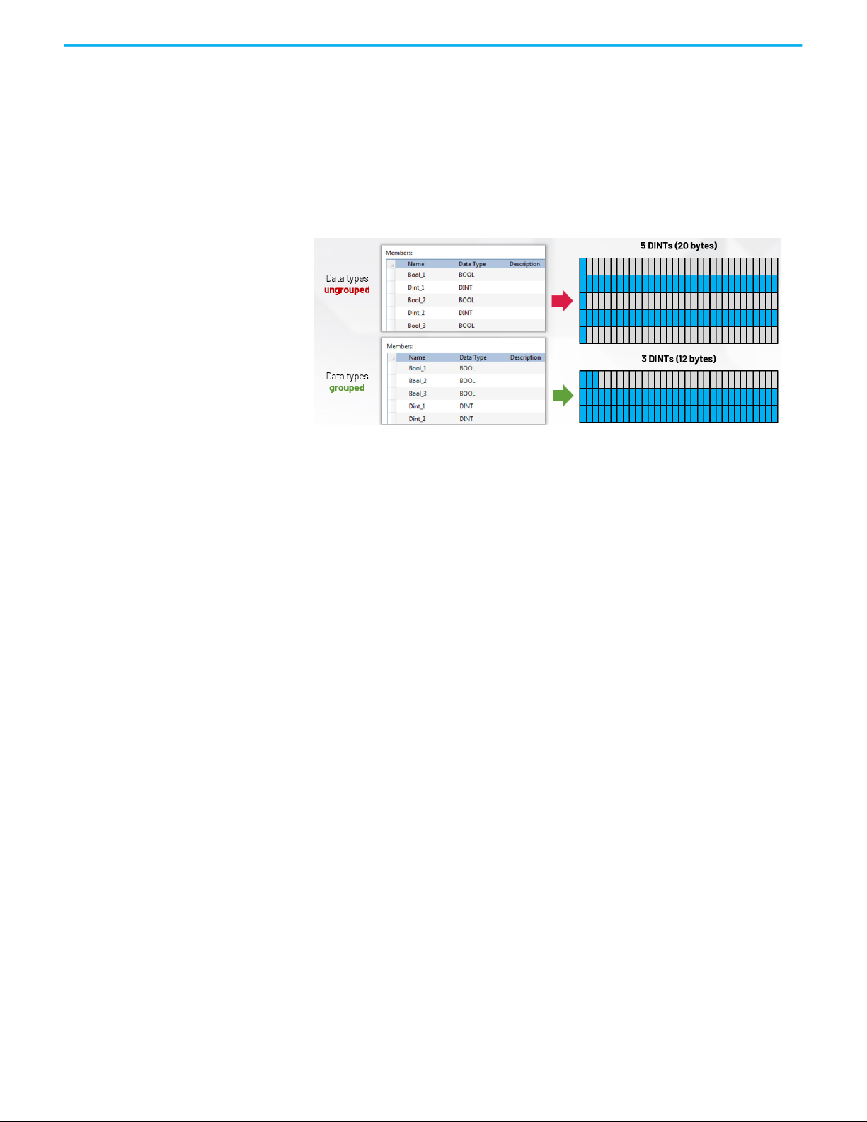
Chapter 6 Programming Best Practices
Group Data Types Together in User-defined Data Types
When you create a user-defined data type for use in your redundancy
program, group like data types together. Grouping like data types compresses
the data size and helps reduce the amount of data that is transferred during a
crossload. Group data into types that equal 32 bits as much as possible (for
example, 32 BOOLs equals 32 bits).
Figure 15 - Example of Bytes Saved by Grouping Like Data
Group Data into Arrays of User-defined Data Types by Frequency of Update
To update the secondary controller, the primary controller divides its memory
into pages of 4096 bytes. When an instruction writes a value to a tag, the 4096
byte memory page that the tag is located in will get flagged for crossloading.
During the next crossload event, all of the used data table memory of each
flagged memory page will be crossloaded.. For example, if your logic writes
only 1 BOOL value to a block and all the data on that page is used, the controller
crossloads the entire page (4096 bytes).
To minimize crossload time, group your data by how frequently it is written to.
Even if the data value doesn't change, if the tag is actively written to (by a MOV,
OTE, data table write, etc.), it counts as a data change.
74 Rockwell Automation Publication 1756-UM015B-EN-P - February 2021
Page 75
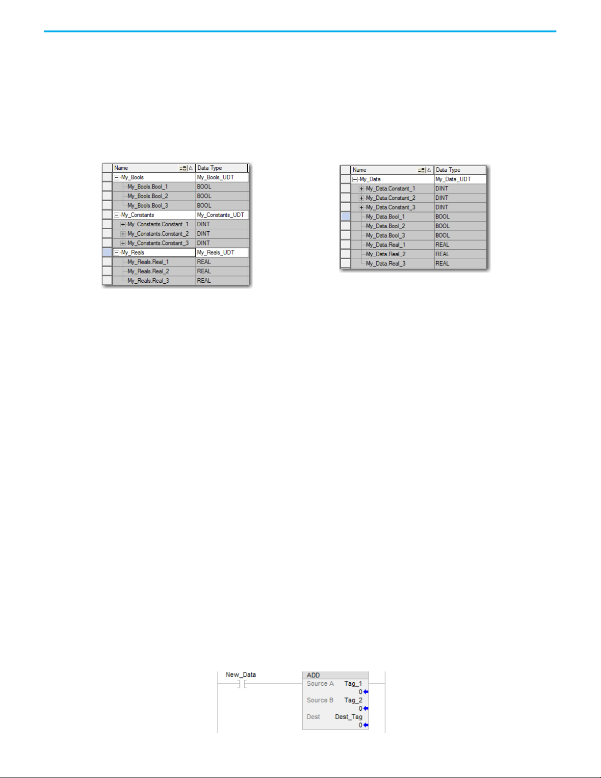
Chapter 6 Programming Best Practices
Tags Grouped into User-defined Data Types by Frequency of Use
Tags in One User-defined Data Type
For example, if your application uses DINTs that you use only as constants to
initialize your logic, BOOLs that you update every scan, and REALs that you
update every second, you can create a separate user-defined data type for each
type of tag that is used at different points in the application. Using separate
user-defined data types for each group, rather than grouping all tags together
in one user-defined data type, helps to minimize the amount of data that is
transferred during the crossload.
Use Concise Programming
Use these recommendations to create concise programming. Using concise
programming makes your program execute faster and reduces your program
scan time.
Execute an Instruction Only when Needed
We recommend that you execute instructions only when needed because each
time an instruction writes a value to a tag, even if the value is not changing, the
used memory of that page (up to 4096 bytes) that contains that tag is flagged
for crossloading.
Because many instructions write tag values whenever executed, strategic and
economical use of instructions is needed. Strategic programming techniques
include the following:
• Use preconditions to limit the execution of instructions.
• Combine preconditions when possible.
• Divide programming into subroutines that are called only when
required.
• Run noncritical code every 2 or 3 scans instead of during every scan.
Rockwell Automation Publication 1756-UM015B-EN-P - February 2021 75
For example, precondition an ADD instruction to run only when the controller
gets new data. As a result, the Dest_Tag is crossloaded only when the ADD
instruction produces a new value.
Figure 16 - Precondition Used with ADD Instruction
Page 76

Chapter 6 Programming Best Practices
In combination with using preconditions, try to group instructions together
that use the same precondition. In this example, the four preconditions that
are used in the two branches can be combined to precede the two branches.
Doing so reduces the number of precondition instructions from four to two.
Figure 17 - Efficient Precondition Use
Program to Maintain Data Integrity
When programming your redundant controllers, there are some instructions
and techniques that can cause data loss or corruption when used. These
instructions and techniques include the following:
• Timer Instructions
• Array (File)/Shift Instructions
• Scan-dependent Logic
Timer Instructions
Timer-based instructions (e.g. TON, TOF, RTO) will continue to time after a
switchover using the same timebase as before the switchover.
76 Rockwell Automation Publication 1756-UM015B-EN-P - February 2021
Page 77

Chapter 6 Programming Best Practices
Array (File)/Shift Instructions
This section only applies when the instructions are modifying controllerscoped data. When there are interruptions to Array (File)/Shift instructions by
a task with the same or higher priority and then a switchover event occurs, it
could result in an incomplete data shift and corrupted data.
The following Array (File)/Shift instructions can result in corrupt data in the
event of a switchover:
• Bit Shift Left (BSL)
• Bit Shift Right (BSR)
• FIFO Unload (FFU)
• File Arithmetic and Logic (FAL)
• File Bit Comparison (FBC)
• Diagnostic Detect (DDT)
• File Sort (SRT)
If Array (File)/Shift Instructions are used, these system behaviors can result:
• If a higher priority task interrupts one of the Array (File)/Shift
instructions, the partially shifted array values are crossloaded to the
secondary controller.
• If a switchover occurs before the instruction completes its execution,
data remains only partially shifted.
• After a switchover, the secondary controller starts executing at the
beginning of the program. When it reaches the partially executed
instruction, it shifts the data again.
Buffering Critical Data
If you cannot place Array (File)/Shift instructions that modify controllerscoped data in the highest-priority task, consider using a buffer with Copy File
(COP) and Synchronous Copy File (CPS) instructions to maintain the integrity
of the array of data.
The programming example that is shown here shows the use of a COP
instruction to move data into a buffer array. The BSL instruction uses the data
in that buffer array. The CPS instruction updates the array tag and maintains
data integrity because a higher priority task cannot interrupt it. If a switchover
occurs, the source data (that is, the array tag) remains unaffected.
Figure 18 - Using a Buffer to Maintain Data During Shift
For more information about BSL, BSR, COP, CPS, DDT, FAL, FBC, FFU, and
SRT instructions, see the Logix 5000 Controllers General Instructions
Reference Manual, publication 1756-RM003
.
Rockwell Automation Publication 1756-UM015B-EN-P - February 2021 77
Page 78
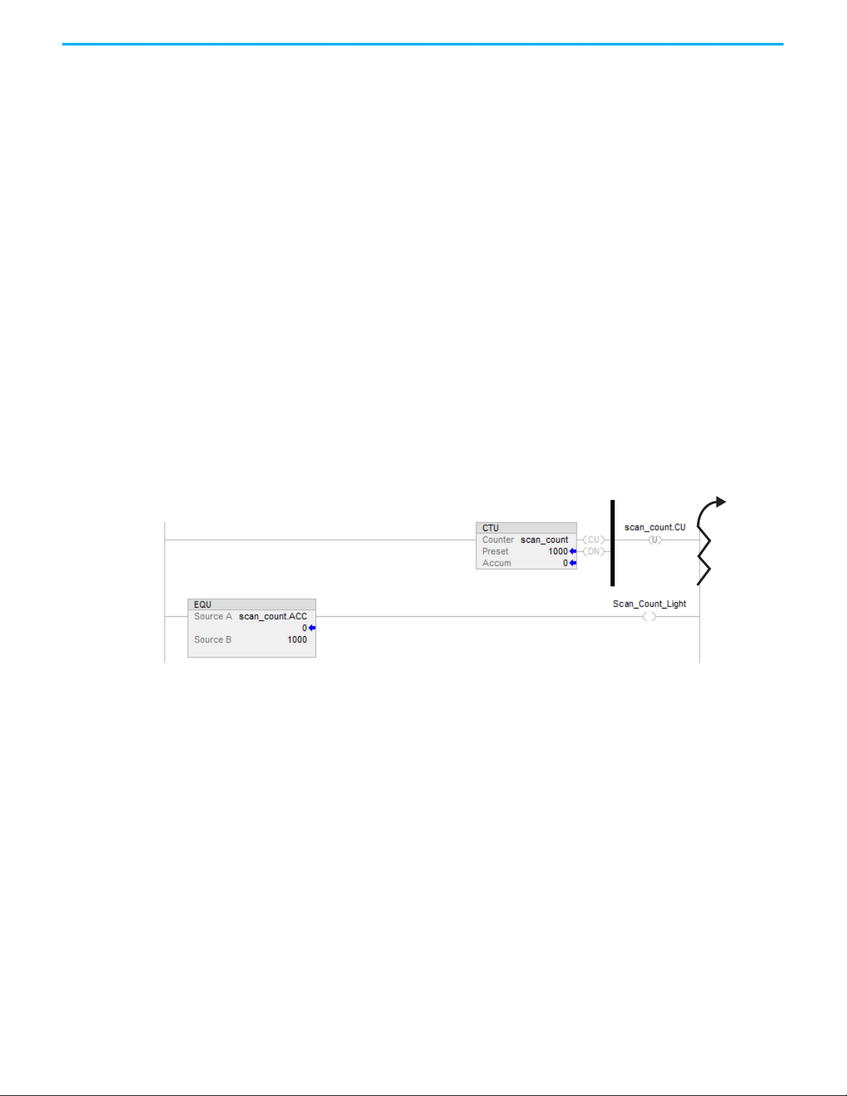
Chapter 6 Programming Best Practices
Interrupt by higher
priority task.
Switchover
Use a Counter instruction to count each scan of the program.
An Equal To instruction uses the accumulated scan_count value as a reference to turn on an indicator when
the thousandth scan is complete.
Scan-dependent Logic
If you use controller-scoped tags and program a lower priority task so that one
instruction is dependent on another instruction that occurs elsewhere in your
program, a task interrupt and switchover can disrupt your programming. The
disruption can occur because the higher priority task can interrupt the lower
priority task and then a switchover can occur before the lower priority task is
completed.
When the lower priority task is executed from the beginning by the new
primary controller after the switchover, the dependent instruction can fail to
execute at the most recent value or state.
For example, if a higher priority task interrupts the logic that is shown in this
example, the value of scan_count.ACC is sent to the secondary controller at the
end of the program in the higher priority task. If a switchover occurs before the
primary controller completes the EQU instruction, the new primary controller
starts its execution at the beginning of the program and the EQU instruction
misses the last value of scan_count.ACC. As a result, any programming that
uses the Scan_Count_Light tag can also execute by using incorrect data.
Scan-dependent Logic
78 Rockwell Automation Publication 1756-UM015B-EN-P - February 2021
Page 79
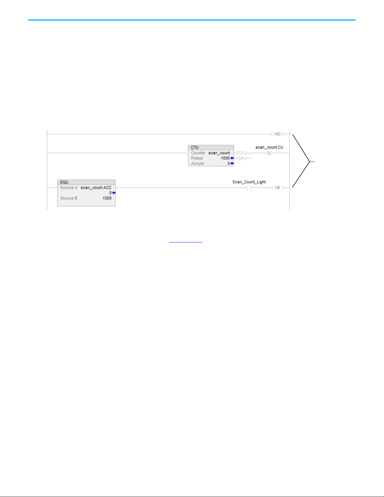
Chapter 6 Programming Best Practices
UID and UIE keep
higher priority tasks
from interrupting the
logic.
Use a Counter instruction to count each scan of the program.
An Equal To instruction uses the accumulated scan_count value as a reference to turn on an indicator when
the thousandth scan is complete.
Bind Dependent Instructions with UID and UIE Instructions
If you cannot place scan-dependent instructions in the highest priority task,
consider using the User Interrupt Disable (UID) and User Interrupt Enable
(UIE) to prevent a higher priority task from interrupting the scan-dependent
logic.
For example, if you bind the scan-dependent logic that is previously shown, a
higher priority task would not interrupt the dependent instructions and a
switchover would not result in inconsistent data.
Scan-dependent Instructions Bound with UID and UIE Instructions
For more information about UID and UIE instructions, see the Logix 5000
Controllers General Instructions Reference Manual,
publication 1756-RM003
.
Rockwell Automation Publication 1756-UM015B-EN-P - February 2021 79
Page 80

Chapter 6 Programming Best Practices
Optimize Tasks To make synchronization, crossloads, and HMI updates as fast as possible,
avoid using a continuous task. Instead, the best practice is to use periodic
tasks. The fewer the number of periodic tasks used, the better the
performance.
IMPORTANT
While the use of a continuous task is fully supported, it is much
easier to manage performance without a continuous task. In
addition, when using a continuous task certain types of
communications performance can be negatively impacted under
various conditions, especially when using heavy messaging or HMI
data table writes of tags to the controller. For more information on
data table writes, see Communications Performance
on page 81.
If you use multiple periodic tasks, verify the following:
• There should be no task overlaps during synchronized steady state. The
execution time of each task should be smaller than its period.
• The total execution time of all your tasks is less than the period of the
task with the largest period.
• The lower priority tasks should have longer periods than higher priority
tasks to allow time for task interruption by the higher priority tasks.
Example of Periodic Task Configurations
Task Priority Execution Time Period Specified
1 Higher 20 ms 80 ms
2 Lower 30 ms 100 ms
Total execution time: 50 ms
In this example, the execution time of the highest priority task (Task 1) is
smaller than its period. The total execution time of all tasks is less than the
specified period of the lowest priority task.
Tuning the Period Specified
Tune the period you specify for your periodic tasks. To check for overlaps, go
online with the controller and access the Task Properties dialog box. In the
Monitor tab, note the maximum scan time. Verify that the maximum scan
time is smaller than the period you specified for the periodic task.
You can also check the Task Overlap Count to see how may task overlaps
occurred since the last reset.
IMPORTANT
Task overlaps are expected during qualification so you should only
check the number of task overlaps while the controller is in a
synchronized steady state.
80 Rockwell Automation Publication 1756-UM015B-EN-P - February 2021
Page 81

Chapter 6 Programming Best Practices
Programming Considerations
Consider the following when programming your redundant controller.
Data Transfer
IMPORTANT
• For data that is known to change very frequently, we recommend to
group it all into a structure. You can then reference each member of this
structure by using the alias functionality, with only minor changes to the
application programming. This can minimize the amount of data that is
required to be transferred.
• Program synch points can be selectively turned off to reduce the
frequency of transferred data. For optimal performance have as few
synch points as the application allows.
For more information see Changing Crossload and Synchronization
Settings on page 61.
When you write to a tag, regardless if the data is the same or
different, the system crossloads it, along with all of the used memory
that is in the same 4096 byte memory page, during the next
configured crossload time. For optimal performance, write to tags
only when necessary (for example, do not write to tags for HMI reads
faster than 2x the update rate).
SSV Instruction Operation
• Modifications made by SSVs are not crossloaded to the secondary while
qualifying, locking, or locked.
Check the module redundancy state, and do not execute SSVs when in
these states if it is important that the operation is reflected on the
secondary.
Communications Performance
Frequent and sustained incoming data table writes (>10/s for minutes) to
controller tag values of a redundant controller can impact the communications
performance of the redundant controller.
Examples of incoming data table writes include:
• Executing a message (MSG) instruction with "CIP Data Table Write"
message type from another controller targeted to the redundant
controller.
• Writing a tag value from an HMI.
• Modifying a tag value while online with the Studio 5000 Logix Designer
Application.
Impacts on communications performance can include:
• Reduced responsiveness while online with Studio 5000 Logix Designer
Application.
• Error (16#000c) reported when a controller with many consuming tags
(>15) attempts to establish connections to the redundant controller's
produced tags.
Rockwell Automation Publication 1756-UM015B-EN-P - February 2021 81
Page 82

Chapter 6 Programming Best Practices
Programed-scoped Tags
• Program-scoped tags remove the need for UID/UIE instructions around
instructions like bit shifts, and can also improve the performance of the
highest priority task.
• Program-scoped tags only help with the performance of higher priority
tasks, so they have no impact on performance for applications with only
one task.
• The ControlLogix® 5580 controller isolates program-scope data from
controller-scope data. At each sync point, the controller transfers the
controller-scope data that is flagged for crossloading, along with all of
the program-scope data flagged for crossloading for all of the programs
that have executed since the last sync point. We recommend to make
more use of program-scoped data, especially when using multiple tasks.
IMPORTANT We recommend not using InOut parameters between programs in
different tasks. This data may not remain bumpless during switchover.
Redundant System Update (RSU) Operation
• RSU is allowed between all ControlLogix 5580 controller types, provided
that the memory size of the controller being migrated to is the same or
larger than the controller being migrated from.
IMPORTANT It may not be possible to migrate between some controllers
based on application constraints (for instance, some features
are only supported on ControlLogix 5580 Process controllers).
• Do not exceed 520 class 3 messages or HMI connections when you
attempt to do an update with RSU, or the lock for update could fail.
Instruction Operation
• You should limit the size of the following; making them as small as
needed for the application:
- Data arrays/structures/UDTs
-AOIs
- FBD routines
• BSR, BSL, FAL, FBC, DDT, SRT, and FFU instructions.
When referencing controller-scoped tags in a lower or same priority task,
partial updates can be crossloaded to the secondary as part of the other
task's sync point. If switchover occurs, the instruction could have
incorrect data. Use UID/UIE pairs around the instruction or use
program-scoped tags instead.
• When performing MSG reads, the MSG backing tag and the data tag
should be at the same scope so that they are tracked together.
82 Rockwell Automation Publication 1756-UM015B-EN-P - February 2021
Page 83

Chapter 6 Programming Best Practices
Alarms
• If a substantial number of alarms (including both Logix tag-based alarms
AND Logix instruction-based alarms) are changing state often (e.g. every
scan cycle), this can prevent redundancy from synchronizing and it can
cause the system to be stuck in a qualifying state until the alarms become
stable.
For more information, see the Knowledgebase Technote ALMA/ALMD
instructions limits
• The alarm burst of a large amount of Logix tag-based alarms can lead to a
significant increase of a task scan time on a synchronized redundant
controller pair.
The scan time increase primarily depends on the number of alarm
conditions changing state during the alarm burst, and also on the level of
nesting of these alarm conditions.
IMPORTANT Each 1 - 25 tag-based alarm conditions established within one
particular scope (each scope is determined by a separate
identifier within the alarm fully qualified name) adds roughly 0.4
ms to the program scan time, while each level of nesting can
add 0.4 ms in the worst case scenario.
Rockwell Automation recommends the following:
- Minimize the number of the alarm conditions which can change state
during a potential alarm burst.
- Avoid excessive nesting of the conditions.
- Perform measurements of potential alarm bursts during system
commissioning and make changes in the commissioned project if
measured scan times are not acceptable.
Diagnostics
• Use GSV instructions to programmatically track and display redundancy
status on an HMI or other user consumable interface. See Monitor
System Status on page 100.
Rockwell Automation Publication 1756-UM015B-EN-P - February 2021 83
Page 84
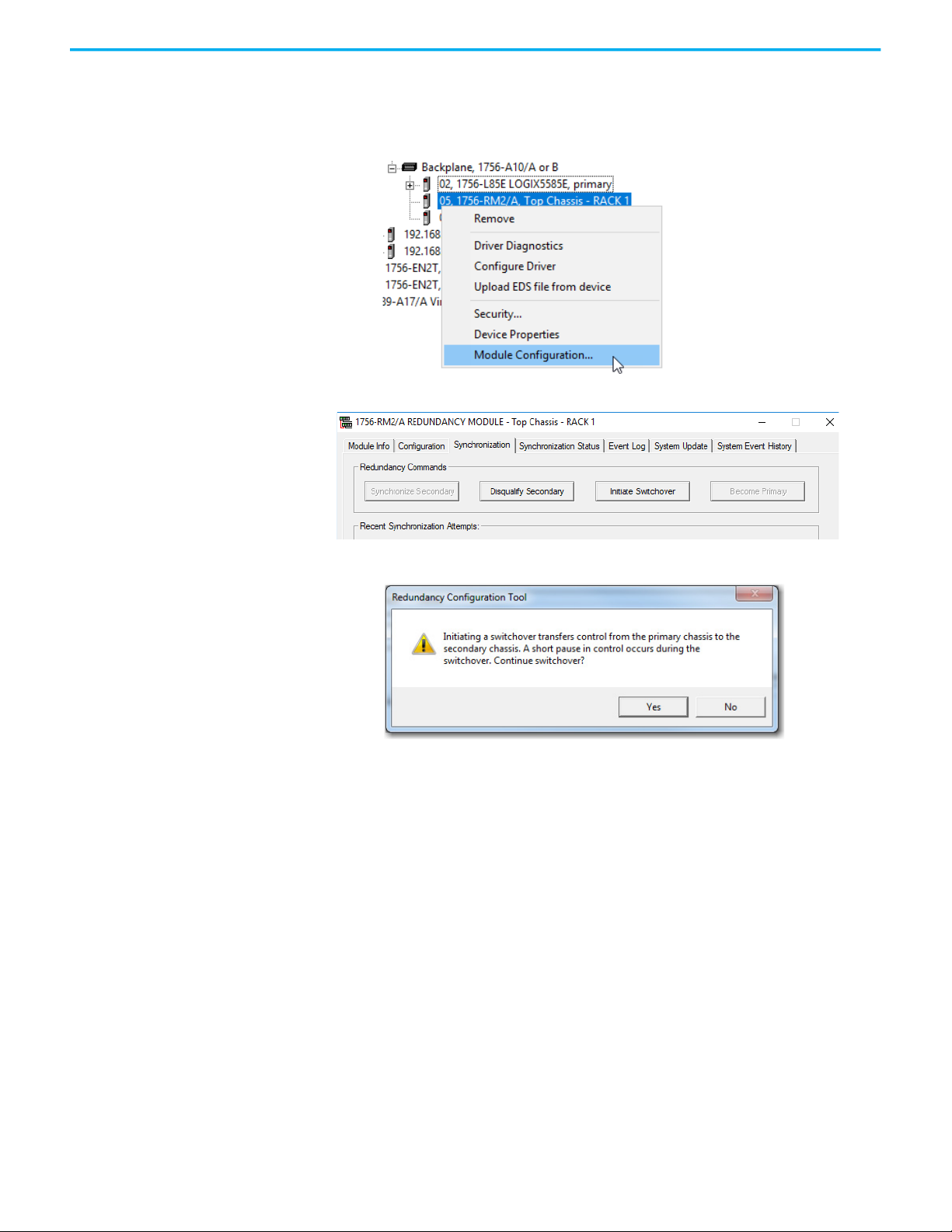
Chapter 6 Programming Best Practices
Conduct a Test Switchover Complete these steps to verify that your redundant system switches over as
expected. Your system must be fully qualified before you begin.
1. In RSLinx® Classic software, access the RMCT for the primary
redundancy module.
2. On the Synchronization tab, click Initiate Switchover.
The Redundancy Configuration Tool dialog box opens
.
3. Click Yes.
The switchover begins.
4. To verify that the switchover was successful, monitor the RM2 status
indicators or the RMCT. You can also view your HMI or other statusmonitoring device.
84 Rockwell Automation Publication 1756-UM015B-EN-P - February 2021
Page 85

Chapter 6 Programming Best Practices
Synchronization After a Switchover
If your Auto-Synchronization parameter is set to Always, your system begins
synchronizing immediately after the switchover.
To monitor the synchronization of your system after you initiate the test
switchover, you can monitor the synchronization process by using these
methods:
• From the RMCT, click the Synchronization Status tab and monitor the
Secondary Readiness column. The states No Partner, Disqualified,
Synchronizing, and Synchronized indicate the stages of
synchronization.
• View the module status display of a primary communication module.
The states PwNS, PsDS, PwQgS, and PwQS indicate the stages of
synchronization. See Table 17 on page 118
qualification status codes.
• View the module status display of the secondary redundancy module.
The states DISQ, QFNG, and SYNC indicate the stages of
synchronization.
• Run a second test switchover where you power off the primary chassis to
initiate the switchover.
for definitions of these
Rockwell Automation Publication 1756-UM015B-EN-P - February 2021 85
Page 86

Chapter 6 Programming Best Practices
This GSV instruction obtains the chassis ID of the primary chassis (that is, the chassis that is in control).
If this is the first program scan, then use the current primary chassis ID as the chassis ID for the last scan.
If a switchover occurs, the chassis ID changes. The NEQ instruction compares the current and last
primary chassis ID values. If the values are different, the Switchover_Occurred bit is turned on.
In addition, the current primary chassis ID is moved into the last chassis ID.
If the Switchover_Occurred bit is on, then the instructions added to this rung are executed and the Switchover_Occurred bit is reset.
Add your switchover-dependent instructions here.
Program Logic to Run After a Switchover
If your application requires certain logic or instructions to be executed after a
switchover, then use programming and tags similar to the values shown in this
example.
Figure 19 - Precondition Used to Run Logic After Switchover - Ladder Logic
86 Rockwell Automation Publication 1756-UM015B-EN-P - February 2021
Page 87
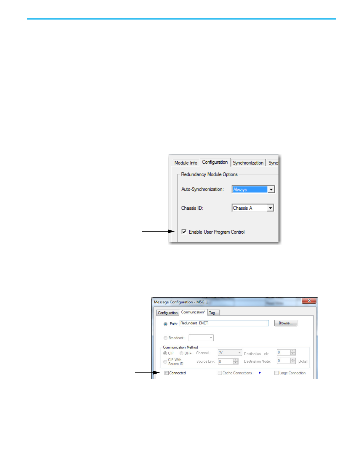
Chapter 6 Programming Best Practices
Use Messages for Redundancy Commands
For some applications, consider programming the controller to issue
redundancy system commands via the redundancy modules. The sections that
follow explain how to configure a MSG instruction to issue a redundancy
command.
Verify User Program Control
For a MSG instruction to issue a command via the redundancy modules, the
redundancy modules must be configured for user program control.
To verify that the modules are enabled for user program control, access the
Configuration tab of the RMCT and verify that Enable User Program Control is
checked.
Figure 20 - Enable User Program Control in the RMCT
Use an Unconnected Message
When you add your MSG instruction for issuing the command through the
redundancy modules, configure it as an unconnected message.
Rockwell Automation Publication 1756-UM015B-EN-P - February 2021 87
Page 88

Chapter 6 Programming Best Practices
Configure the MSG Instruction
Use the MSG configuration settings that correspond to the command you
intend to issue to the redundancy modules.
If you must See page
Initiate a Switchover 88
Disqualify the Secondary Chassis 89
Synchronize the Secondary Chassis 90
Set the Redundancy Module Date and Time 90
Initiate a Switchover
To initiate a switchover, use the MSG instruction parameters that are listed in
Table 6
Table 6 - MSG Instruction to Initiate a Switchover
.
In this tab Edit this element To use this value
Message Type CIP™ Generic
Service Type Custom
Service Code 4e
Class bf
Configuration
Communication
Instance 1
Attribute None - no value needed
Source Element INT tag with a value of 1
Source Length 2
Destination Element None - no value needed.
Path
Connected box Leave the Connected checkbox unchecked.
1 - the slot number of the 1756-RM2 or 1756-RM2XT
module.
Use Table 7
when using MSG instructions during a switchover.
Table 7 - MSG Instruction Behavior During a Switchover
If the MSG instruction is Then
From a redundant controller
To a redundant controller
If the MSG instruction
originates from a
redundant controller
During a switchover
During qualification
In a redundant controller, any MSG instruction that is in progress during a switchover experiences an error.
(The ER bit of the instruction turns on.) After the switchover, normal communication resumes.
For any MSG instruction from a controller in another chassis to a redundant controller, cache the connection:
Properties of the Message to the Redundant Controller
Configured Message Instructions
The message instructions status bits are updated asynchronously to the program scan. Consequently, you cannot crossload
your message instructions status bits to a secondary controller.
During a switchover, any active message instructions become inactive. When this change occurs, you must reinitialize the
execution of your message instructions in the new primary controller.
The scrolling display changes from CMPT for compatible to Qfng for qualifying.
• If a configured message is cached, the primary controller automatically establishes a connection with no errors.
• If a configured message is uncached or unconnected, the primary controller receives Error 1 Extended Error 301, No Buffer
Memory.
Then
88 Rockwell Automation Publication 1756-UM015B-EN-P - February 2021
Page 89

Table 7 - MSG Instruction Behavior During a Switchover
Chapter 6 Programming Best Practices
If the message is targeted to a
redundant controller
During the erroring out of a message
During qualification
Then
All message communication ceases. This stoppage lets the redundant controller receive the message instruction that is
required to perform a switchover or any diagnostics.
Important: If any of your messages are active during a switchover, you can expect one of these things to happen:
• Cached and connected messages cause the message instruction to pause for 7.5 seconds because the initiating controller
has not received a response from the targeted controller. For cached messages, the message instruction tries to execute
three more times, each attempt followed by a pause of 7.5 seconds. If, after 30 seconds pass, the targeted controller does not
respond to the initiating controller, then the switchover errors out with connected time-out Error 1 Extended Error 203.
An example of a connected message would be CIP data table read-and-write messages after a
connection has been established.
• Uncached messages error out after 30 seconds if you have initiated them because the initiating controller never received a
reply to the forward-open request. The error is Error 1F Extended Error 204, an unconnected time-out.
Examples of uncached messages would include CIP generic messages and messages that are captured during the
connection process.
Cached messages that run with no errors. A connection has been established.
Connected, but uncached, messages or unconnected messages error out with Error 1 Extended Error 301, No
Buffer Memory.
Disqualify the Secondary Chassis
To disqualify the secondary chassis, use the MSG instruction parameters that
are listed in Table 8
Table 8 - Disqualify the Secondary Chassis
In this tab Edit this element To use this value
Configuration
Communication
.
Message Type CIP Generic
Service Type Custom
Service Code 4d
Class bf
Instance 1
Attribute None - no value needed
Source Element INT tag with a value of 1
Source Length 2
Destination Element None - no value needed.
Path
Connected box Leave the Connected checkbox unchecked.
1 - the slot number of the 1756-RM2 or
1756-RM2XT module.
Rockwell Automation Publication 1756-UM015B-EN-P - February 2021 89
Page 90
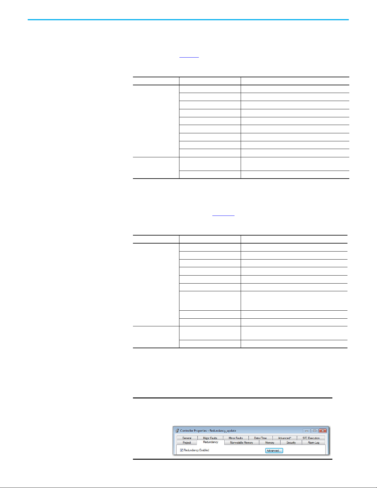
Chapter 6 Programming Best Practices
Synchronize the Secondary Chassis
To synchronize the secondary controller, use the MSG instruction parameters
that are listed in Table 9
.
Table 9 - Synchronize the Secondary Chassis
In this tab Edit this element To use this value
Message Type CIP Generic
Service Type Custom
Service Code 4c
Class bf
Configuration
Communication
Instance 1
Attribute None - no value needed
Source Element INT tag with a value of 1
Source Length 2
Destination Element None - no value needed.
Path
Connected box Leave the Connected checkbox unchecked.
1 - the slot number of the 1756-RM2 or 1756-RM2XT
module.
Set the Redundancy Module Date and Time
To set the WallClockTime of the 1756-RM2 module, use the MSG instruction
parameters that are listed in Table 10
.
Table 10 - Set WallClockTime
In this tab Edit this element To use this value
Message Type CIP Generic
Service Type Custom
Service Code 10
Class 8b
Configuration
Communication
Instance 1
Attribute b
Source Element
Source Length 8
Destination Element None - no value needed.
Path
Connected box Leave the Connected checkbox unchecked.
WallClockTime[0]
WallClockTime is a DINT[2] array that stores the
CurrentValue of the WallClockTime object
1 - the slot number of the 1756-RM2 or 1756-RM2XT
module.
Download the Project Download the project only to the primary controller. When the secondary
controller is synchronized, the system automatically crossloads the project to
the secondary controller.
IMPORTANT
If the secondary chassis was qualified and becomes disqualified
after you download the project, verify that you have enabled the
controller for redundancy.
90 Rockwell Automation Publication 1756-UM015B-EN-P - February 2021
Page 91

Chapter 6 Programming Best Practices
Store a Redundancy Project to Nonvolatile Memory
Use this procedure to store an updated project and firmware to the nonvolatile
memory card of the controller.
This section describes how to store a project to nonvolatile memory in either of
these conditions:
• Store a Project While the Controller is in Program or Remote Program
Mode
• Store a Project While a System is Running
IMPORTANT
We recommend that you store the same project on the nonvolatile
memory cards of both controllers. By doing so, you can be assured that if
a controller, primary or secondary, loses the project from its internal
memory, you can load the most recent project back onto that controller.
If you store the same project on the nonvolatile memory cards of both
controllers, while the process is running, you must save the project on
the controllers while they are in the secondary controller state. To do so,
you save the project on the secondary controller, conduct a switchover,
and save the project on the new secondary controller. Even if you do not
plan to use the SD card, leave the card installed in the controller to
collect diagnostic information that you can provide to Rockwell
Automation Technical Support.
For more information, see the steps in Store a Project While the
Controller is in Program or Remote Program Mode on page 91 or Store a
Project While a System is Running on page 92.
Store a Project While the Controller is in Program or Remote Program Mode
If you want to store your controller project in nonvolatile memory while your
redundant system is not running, complete these steps. Before you begin,
verify that a controller communication path has been specified and that you
are able to go online with the primary controller.
1. Verify that the redundant chassis are synchronized. If they are not
synchronized, synchronize them.
2. To put the primary controller into Program or Remote Program mode,
use programming software or the keyswitch.
3. In RSLinx Classic communication software, right-click the redundancy
module and choose Module Configuration to open the RMCT.
If you cannot see the Module Configuration option in the list, then the compatible
version of the RMCT is not installed.
Rockwell Automation Publication 1756-UM015B-EN-P - February 2021 91
Page 92

Chapter 6 Programming Best Practices
4. In the Configuration tab, set the Auto-Synchronization parameter to
Conditional.
5. On the Synchronization tab, click Disqualify Secondary.
6. In the programming software, access the Controller Properties dialog
box and click the Nonvolatile Memory tab.
7. Click Load/Store.
8. Click <-- Store and then click Yes.
When the store is complete, go online with the secondary controller.
9. Complete steps 6
…8 to store the project in nonvolatile memory of the
secondary controller.
10. In RSLinx Classic software, open the RMCT for one of the redundancy
modules in the redundant pair.
11. In the Synchronization tab, click Synchronize Secondary.
12. In the Configuration tab, set the Auto-Synchronization option to your
desired setting.
Store a Project While a System is Running
If you want to store your controller project in nonvolatile memory while your
redundant system is running, complete these steps.
1. Verify that the redundant chassis are synchronized.
2. In the RMCT, access the Configuration tab and set the AutoConfiguration parameter to Never.
3. In the Synchronization tab, click Disqualify Secondary.
92 Rockwell Automation Publication 1756-UM015B-EN-P - February 2021
Page 93
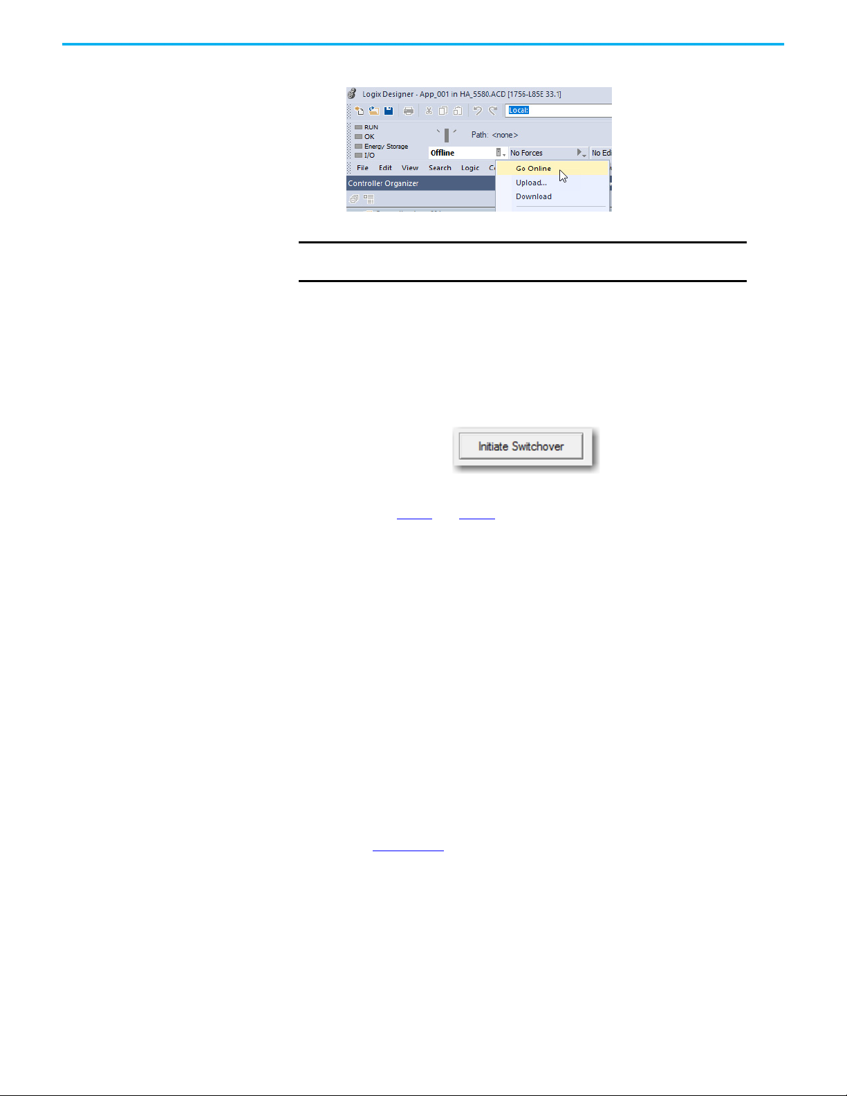
4. Go online with the secondary controller.
Chapter 6 Programming Best Practices
IMPORTANT
Do not go online with the primary controller until you have
completed this procedure.
5. Open the Controller Properties dialog box and click the Nonvolatile
Memory tab.
6. To store the project in nonvolatile memory, click Load/Store then <-Store.
7. In the RMCT, click the Synchronization tab.
8. Click Synchronize Secondary and wait for the system to synchronize.
9. Click Initiate Switchover.
10. Go online with the new secondary controller.
11. Complete step 5
and step 6 to store the project.
12. In the RMCT, click the Configuration tab and set the Auto-Configuration
to your desired setting.
13. In the Synchronization tab, click Synchronize Secondary.
You have completed the steps that are required to store your project
while online.
Load a Project
If you must load a project from nonvolatile memory, you must first disqualify
your redundancy system. You then load the project from the nonvolatile
memory card to the primary controller, and resynchronize the redundant
chassis once the load is complete.
For details about loading a project from nonvolatile memory, see the Logix
5000 Controllers Nonvolatile Memory Card Programming Manual,
publication 1756-PM017
Rockwell Automation Publication 1756-UM015B-EN-P - February 2021 93
.
Page 94

Chapter 6 Programming Best Practices
Online Edits You can edit the redundant controller program while the system is online and
running. However, considerations specific to redundancy must be made with
considerations described in the Logix 5000 Controllers Quick Start,
publication 1756-QS001
Partial Import Online (PIO)
Consider these points when using PIO with redundancy systems:
• If you select Import Logix Edits as Pending or Accept Program Edits
when executing a PIO, the primary controller treats the PIO feature as a
set of multiple test edits where, after the import is complete, you can
switch between testing the edits or not.
• We recommend that you do not use Finalize All Edits in Program when
you import edits. If you use this option, any failure due to the import
causes a failure on the new primary controller after a switchover. If the
new edits cause the controller to major fault, both the primary and
secondary will major fault, resulting in loss of control.
• If edits exist in the primary controller due to a PIO, they are treated the
same as normal test edits regarding the ‘Retain Test Edits at Switchover’
selection and Redundancy System Update.
• If a PIO is in progress, the primary controller rejects any attempt to
qualify.
• If you attempt to initiate a PIO on a primary controller in the process of
qualifying the system, that PIO is rejected.
• If a switchover occurs while the PIO is still in process, a PIO to the new
primary controller can either fully abort or fully complete, depending on
how far the PIO had proceeded at the time of switchover.
.
If the PIO does not complete due to the switchover, reattempt the PIO
after the system has synchronized.
There are additional considerations necessary to performing online edits:
• Plan for Test Edits
• Assemble Edits with Caution
94 Rockwell Automation Publication 1756-UM015B-EN-P - February 2021
Page 95
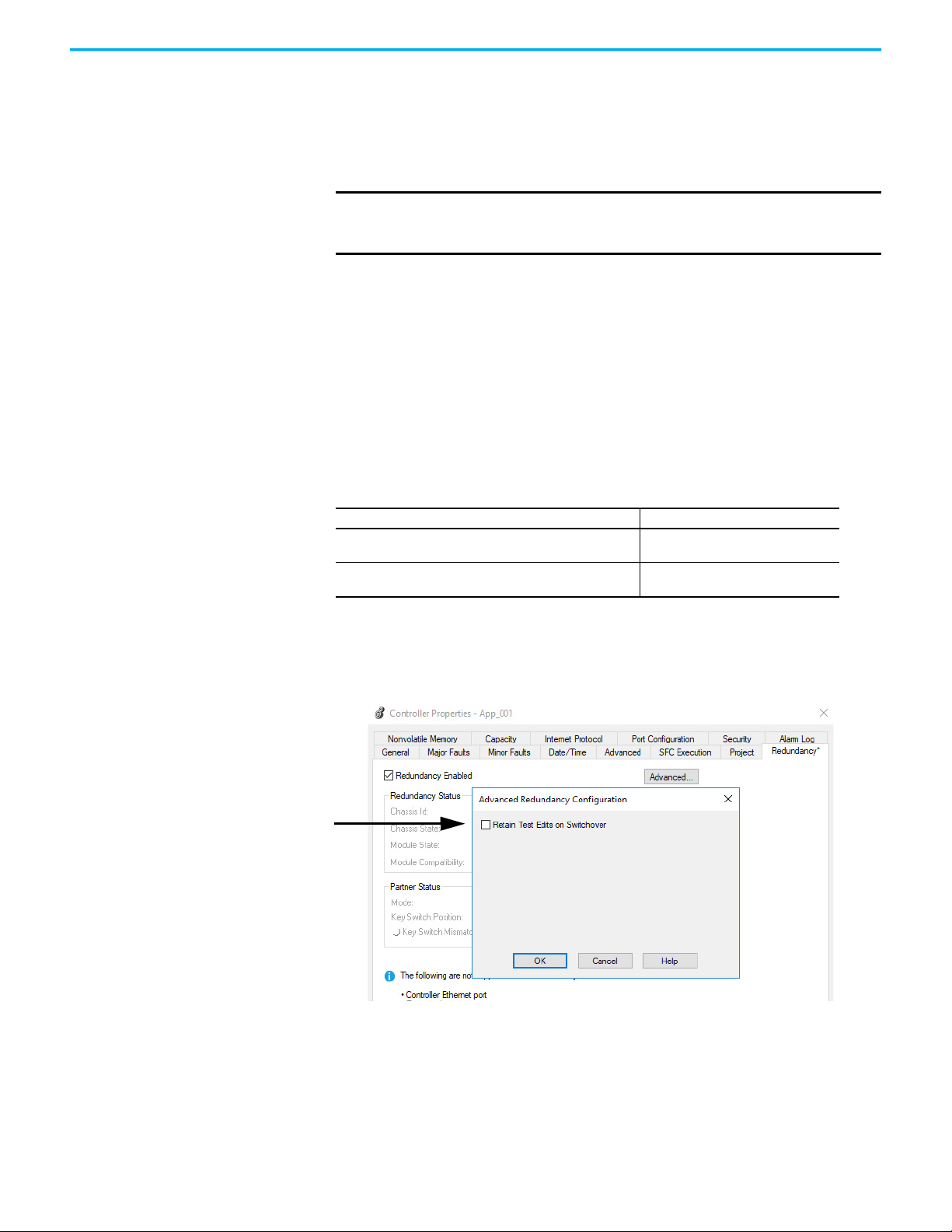
Chapter 6 Programming Best Practices
Plan for Test Edits
Before you begin editing your redundant program while your system is
running, verify that the Retain Test Edits on Switchover setting meets your
application requirements.
IMPORTANT
We recommend that you leave the Retain Test Edits on Switchover
setting at the default (that is, unchecked) to avoid faulting both
controllers when testing your edits.
If you enable the system to retain the test edits on a switchover (that is, you
check Retain Test Edits on Switchover), faults that result from the test edits
can also occur on the new primary controller after a switchover.
If you do not enable the system to retain the test edits on a switchover (that is,
you leave Retain Test Edits on Switchover unchecked), faults that result from
the test edits are not carried over to the new primary controller in the event of
a switchover.
Use this table to determine the Retain Test Edits on Switchover setting that
suits your application.
If you must Then
Prevent a test edit from faulting both the primary and
secondary controller
Keep test edits active, even in the event of a switchover and at
the risk of faulting both controllers
Leave Retain Test Edits on Switchover
unchecked
Check Retain Test Edits on Switchover
To change the Retain Test Edits on Switchover setting, click the Redundancy
tab in the Controller Properties then click Advanced.
Figure 21 - Retain Test Edits on Switchover
Rockwell Automation Publication 1756-UM015B-EN-P - February 2021 95
Page 96

Chapter 6 Programming Best Practices
Accept Pending Program Edits
Verify Routine
Assemble Edits with Caution
When you assemble edits to your program while online, the original program
that existed before the changes were made is deleted. As a result, if the edits
you assemble cause a fault on the primary controller, the new primary
controller also faults after the switchover. Also, when you assemble edits in the
primary controller, the edits are also assembled in the secondary controller.
Before you assemble any edits to your program, test the edits to verify that
faults do not occur.
1. In the Controller Organizer, open the routine you must edit.
2. Make the appropriate changes to your routine.
3. Click the Verify Routine button.
4. Click the Accept Pending Program Edits button.
Figure 22 - Test Edits Before Finalizing
Even if you have not enabled the Retain Test Edits on Switchover property, faults
can still occur on the primary and secondary controllers if the edits are
assembled.
The Retain Test Edits on Switchover property affects only edits that are being
tested. The Retain Test Edits on Switchover does not affect the redundant
controllers that are running assembled edits.
5. At the Accept the Pending Edits dialog box, click Yes.
96 Rockwell Automation Publication 1756-UM015B-EN-P - February 2021
Page 97

6. Click Test Accepted Program Edits.
Test Ac cepted Progr am Edits
Finalize All Edits
7. At the dialog box, click Yes.
Chapter 6 Programming Best Practices
Rockwell Automation Publication 1756-UM015B-EN-P - February 2021 97
8. Click Assemble Accepted Program Edits.
Page 98

Chapter 6 Programming Best Practices
9. At the dialog box, click Yes.
Your edits are now assembled.
98 Rockwell Automation Publication 1756-UM015B-EN-P - February 2021
Page 99

Chapter 7
Monitor and Maintain a Redundancy System
Top ic Pa ge
Controller Logging 99
Monitor System Status 100
Verify Date and Time Settings 102
Verify System Qualification 103
Check the EtherNet/IP Module Status 106
This chapter describes some of the key tasks to complete to monitor and
maintain your redundancy system.
Controller Logging Controller logging provides a way to detect and log changes. These changes
include programming software and controller keyswitch interactions made to
ControlLogix® 5580 controllers, without adding any auditing software.
With controller logging, the controller can perform these tasks:
• Detect changes and create log entries that contain information about the
changes.
• Store the log entries to a Secure Digital (SD) card for later review.
• Provide programmatic access to log entry counters to provide change
detection information remotely.
Controller Log
A controller log is the record of changes. The log is stored on the NVS memory
of the controller automatically. You can move the log to an SD card on an
as-needed basis or automatically at predefined times. The NVS memory of the
controller and each external memory card type has a maximum number of
entries that they can store.
Specific events are stored in the log of the controller.
For more information on controller logging, see the Logix 5000 Controllers
Information and Status Programming Manual, publication 1756-PM015
.
Rockwell Automation Publication 1756-UM015B-EN-P - February 2021 99
Page 100

Chapter 7 Monitor and Maintain a Redundancy System
Controller Logging in Redundancy Systems
Because redundancy systems operate with partnered controllers, there are
considerations that you must consider regarding controller logging:
• The primary and secondary controllers maintain separate logs.
• You do not need to synchronize the logs.
• On the primary controller, controller logging occurs exactly as it does on
• A secondary controller logs the removal or insertion of an SD card, in any
Component Change Detection
Component tracking allows you to determine whether tracked routines,
Add-On Instructions, and constant tags have been changed. The Studio 5000
Logix Designer® application creates a tracked value to indicate the current
state of all components.
a controller in a non-redundant system, regardless of whether the system
is qualified and synchronized or disqualified.
operating state. Otherwise, the secondary controller only logs events that
occur when the controller is in a disqualified state.
Monitor System Status
For more information, see the Logix 5000 Controllers Information and Status
Programming Manual, publication 1756-PM015
IMPORTANT
For most redundant applications, you must program to obtain the status of the
system. Program to obtain system status when you do the following:
• Program HMI to display the system status
• Precondition logic to execute based on the system status
• Use the diagnostic information to troubleshoot the system
To obtain the status of your redundant system, use a Get System Value (GSV)
instruction in your program and plan for the tags you are writing the values to.
When programming your redundancy system, program so your
redundancy system status is continually monitored and displayed on
your HMI device.
If your redundancy system becomes disqualified or a switchover
occurs, the change in status is not automatically annunciated. You
must program the system to communicate the change in status via
your HMI or other status-monitoring device.
.
100 Rockwell Automation Publication 1756-UM015B-EN-P - February 2021
 Loading...