

Page 1

ControlLogix 5570/5560 Redundancy
User Manual
Original Instructions
Page 2
ControlLogix 5570/5560 Redundancy User Manual
Important User Information
Read this document and the documents listed in the additional resources section about installation, configuration, and
operation of this equipment before you install, configure, operate, or maintain this product. Users are required to familiarize
themselves with installation and wiring instructions in addition to requirements of all applicable codes, laws, and standards.
Activities including installation, adjustments, putting into service, use, assembly, disassembly, and maintenance are required to
be carried out by suitably trained personnel in accordance with applicable code of practice.
If this equipment is used in a manner not specified by the manufacturer, the protection provided by the equipment may be
impaired.
In no event will Rockwell Automation, Inc. be responsible or liable for indirect or consequential damages resulting from the use
or application of this equipment.
The examples and diagrams in this manual are included solely for illustrative purposes. Because of the many variables and
requirements associated with any particular installation, Rockwell Automation, Inc. cannot assume responsibility or liability for
actual use based on the examples and diagrams.
No patent liability is assumed by Rockwell Automation, Inc. with respect to use of information, circuits, equipment, or software
described in this manual.
Reproduction of the contents of this manual, in whole or in part, without written permission of Rockwell Automation, Inc., is
prohibited.
Throughout this manual, when necessary, we use notes to make you aware of safety considerations.
WA RN I NG : Identifies information about practices or circumstances that can cause an explosion in a hazardous environment,
which may lead to personal injury or death, property damage, or economic loss.
ATTENTION: Identifies information about practices or circumstances that can lead to personal injury or death, property
damage, or economic loss. Attentions help you identify a hazard, avoid a hazard, and recognize the consequence.
IMPORTANT Identifies information that is critical for successful application and understanding of the product.
Labels may also be on or inside the equipment to provide specific precautions.
SHOCK HAZARD: Labels may be on or inside the equipment, for example, a drive or motor, to alert people that dangerous
voltage may be present.
BURN HAZARD: Labels may be on or inside the equipment, for example, a drive or motor, to alert people that surfaces may
reach dangerous temperatures.
ARC FLASH HAZARD: Labels may be on or inside the equipment, for example, a motor control center, to alert people to potential
Arc Flash. Arc Flash will cause severe injury or death. Wear proper Personal Protective Equipment (PPE). Follow ALL Regulatory
requirements for safe work practices and for Personal Protective Equipment (PPE).
2 Rockwell Automation Publication 1756-UM535I-EN-P - October 2020
Page 3

Table of Contents
Preface . . . . . . . . . . . . . . . . . . . . . . . . . . . . . . . . . . . . . . . . . . . . . . . . . . . . . . . .9
Summary of Changes . . . . . . . . . . . . . . . . . . . . . . . . . . . . . . . . . . . . . . . . . . . 9
Overview . . . . . . . . . . . . . . . . . . . . . . . . . . . . . . . . . . . . . . . . . . . . . . . . . . . . . . 9
Additional Resources . . . . . . . . . . . . . . . . . . . . . . . . . . . . . . . . . . . . . . . . . . . 9
Chapter 1
About ControlLogix
Redundancy Systems
Design a ControlLogix
Redundancy System
Features of the ControlLogix Redundancy System . . . . . . . . . . . . . . . 12
Redundancy System Components . . . . . . . . . . . . . . . . . . . . . . . . . . . . . . 13
I/O Modules in Redundancy Systems . . . . . . . . . . . . . . . . . . . . . . . 14
Redundancy System Operations . . . . . . . . . . . . . . . . . . . . . . . . . . . . . . . . 15
System Qualification and Synchronization. . . . . . . . . . . . . . . . . . . 15
Switchovers . . . . . . . . . . . . . . . . . . . . . . . . . . . . . . . . . . . . . . . . . . . . . . . 16
Restrictions. . . . . . . . . . . . . . . . . . . . . . . . . . . . . . . . . . . . . . . . . . . . . . . . . . . 19
Chapter 2
Redundant Chassis . . . . . . . . . . . . . . . . . . . . . . . . . . . . . . . . . . . . . . . . . . . . 21
Redundant Chassis Configuration Requirements . . . . . . . . . . . . 22
Controllers in Redundant Chassis . . . . . . . . . . . . . . . . . . . . . . . . . . . . . . 22
Redundancy Modules in Redundant Chassis. . . . . . . . . . . . . . . . . 24
Communication Modules in Redundant Chassis. . . . . . . . . . . . . 25
Power Supplies and Redundant Power Supplies in
Redundancy Systems. . . . . . . . . . . . . . . . . . . . . . . . . . . . . . . . . . . . . . . 27
EtherNet/IP Networks with Redundant Systems . . . . . . . . . . . . . . . . 28
Unicast Functionality. . . . . . . . . . . . . . . . . . . . . . . . . . . . . . . . . . . . . . 28
Possible Communication Delays on EtherNet/IP and
ControlNet Networks . . . . . . . . . . . . . . . . . . . . . . . . . . . . . . . . . . . . . 28
Bridge from an EtherNet/IP Network to a ControlNet
Network. . . . . . . . . . . . . . . . . . . . . . . . . . . . . . . . . . . . . . . . . . . . . . . . . . 29
ControlNet Networks with Redundant Systems . . . . . . . . . . . . . . . . . 30
ControlNet Network Requirements . . . . . . . . . . . . . . . . . . . . . . . . 30
Redundant ControlNet Media . . . . . . . . . . . . . . . . . . . . . . . . . . . . . 33
Other Communication Networks . . . . . . . . . . . . . . . . . . . . . . . . . . . . . . 34
I/O Placement . . . . . . . . . . . . . . . . . . . . . . . . . . . . . . . . . . . . . . . . . . . . . . . . 36
1715 Redundant I/O Systems . . . . . . . . . . . . . . . . . . . . . . . . . . . . . . 36
Using HMI. . . . . . . . . . . . . . . . . . . . . . . . . . . . . . . . . . . . . . . . . . . . . . . . . . . 38
HMI Connected Via an EtherNet/IP Network . . . . . . . . . . . . . . 38
HMI Connected Via a ControlNet Network . . . . . . . . . . . . . . . . 39
Optional Software. . . . . . . . . . . . . . . . . . . . . . . . . . . . . . . . . . . . . . . . . . . . . 41
Rockwell Automation Publication 1756-UM535I-EN-P - October 2020 3
Page 4

Table of Contents
Chapter 3
Install the Redundancy System Before You Begin. . . . . . . . . . . . . . . . . . . . . . . . . . . . . . . . . . . . . . . . . . . . . . 43
Redundancy System Quick Start. . . . . . . . . . . . . . . . . . . . . . . . . . . . . . . . 43
Install the Hardware. . . . . . . . . . . . . . . . . . . . . . . . . . . . . . . . . . . . . . . . . . . 45
Install the First Chassis . . . . . . . . . . . . . . . . . . . . . . . . . . . . . . . . . . . . 45
Install the Redundancy Module. . . . . . . . . . . . . . . . . . . . . . . . . . . . . 46
Environment and Enclosure . . . . . . . . . . . . . . . . . . . . . . . . . . . . . . . . 47
Prevent Electrostatic Discharge . . . . . . . . . . . . . . . . . . . . . . . . . . . . . 47
Removal and Insertion Under Power (RIUP) . . . . . . . . . . . . . . . . 47
European Hazardous Location Approval . . . . . . . . . . . . . . . . . . . . 48
Safety-related Programmable Electronic Systems . . . . . . . . . . . . . 48
Optical Ports. . . . . . . . . . . . . . . . . . . . . . . . . . . . . . . . . . . . . . . . . . . . . . 48
Small Form-factor Pluggable. . . . . . . . . . . . . . . . . . . . . . . . . . . . . . . . 48
North American Hazardous Location Approval. . . . . . . . . . . . . . 49
Laser Radiation Ports . . . . . . . . . . . . . . . . . . . . . . . . . . . . . . . . . . . . . . 50
Install the Second Chassis . . . . . . . . . . . . . . . . . . . . . . . . . . . . . . . . . . 52
Connect the Redundancy Modules . . . . . . . . . . . . . . . . . . . . . . . . . . . . . 52
Connect the Fiber-optic Communication Cable to
Redundant Channels . . . . . . . . . . . . . . . . . . . . . . . . . . . . . . . . . . . . . . 54
Connect the Fiber-optic Communication Cable to
Single Channels . . . . . . . . . . . . . . . . . . . . . . . . . . . . . . . . . . . . . . . . . . . 55
Fiber-optic Cable. . . . . . . . . . . . . . . . . . . . . . . . . . . . . . . . . . . . . . . . . . 56
Use Dual Fiber Ports with the 1756-RM2 Redundancy
Module . . . . . . . . . . . . . . . . . . . . . . . . . . . . . . . . . . . . . . . . . . . . . . . . . . . 57
Update Redundant Firmware . . . . . . . . . . . . . . . . . . . . . . . . . . . . . . . . . . 58
Upgrade the Firmware in the First Chassis. . . . . . . . . . . . . . . . . . . 58
Upgrade the Firmware in the Second Chassis . . . . . . . . . . . . . . . . 61
Designate the Primary and Secondary Chassis . . . . . . . . . . . . . . . . . . . 61
After Designation . . . . . . . . . . . . . . . . . . . . . . . . . . . . . . . . . . . . . . . . . 62
Conversion from a Non-redundant to a Redundant System . . . 62
Qualification Status Via the RMCT . . . . . . . . . . . . . . . . . . . . . . . . 63
Reset the Redundancy Module . . . . . . . . . . . . . . . . . . . . . . . . . . . . . 63
Remove or Replace the Redundancy Module. . . . . . . . . . . . . . . . . 64
Chapter 4
Configure the EtherNet/IP
Network
4 Rockwell Automation Publication 1756-UM535I-EN-P - October 2020
Requested Packet Interval. . . . . . . . . . . . . . . . . . . . . . . . . . . . . . . . . . . . . . 65
CPU Usage . . . . . . . . . . . . . . . . . . . . . . . . . . . . . . . . . . . . . . . . . . . . . . . 65
IP Address Swapping . . . . . . . . . . . . . . . . . . . . . . . . . . . . . . . . . . . . . . . . . . 66
Static Versus Dynamic IP Addresses. . . . . . . . . . . . . . . . . . . . . . . . . 68
Reset the IP Address for an EtherNet/IP Communication
Module . . . . . . . . . . . . . . . . . . . . . . . . . . . . . . . . . . . . . . . . . . . . . . . . . . . 68
CIP Sync . . . . . . . . . . . . . . . . . . . . . . . . . . . . . . . . . . . . . . . . . . . . . . . . . . . . . 69
Produce/Consume Connections . . . . . . . . . . . . . . . . . . . . . . . . . . . . . . . 72
Page 5

Table of Contents
Configure EtherNet/IP Communication Modules in a
Redundant System . . . . . . . . . . . . . . . . . . . . . . . . . . . . . . . . . . . . . . . . . . . . 75
Before You Begin. . . . . . . . . . . . . . . . . . . . . . . . . . . . . . . . . . . . . . . . . . 75
Options for Setting the IP Addresses of EtherNet/IP
Communication Modules. . . . . . . . . . . . . . . . . . . . . . . . . . . . . . . . . . 75
Half/Full Duplex Settings. . . . . . . . . . . . . . . . . . . . . . . . . . . . . . . . . . 75
Use a Redundancy System with Device Level Ring . . . . . . . . . . . . . . . 76
Use a Redundancy System with Parallel Redundancy Protocol . . . . 77
Chapter 5
Configure the ControlNet
Network
Configure the Redundancy
Modules
Produce/Consume Connections . . . . . . . . . . . . . . . . . . . . . . . . . . . . . . . 79
Network Update Time . . . . . . . . . . . . . . . . . . . . . . . . . . . . . . . . . . . . . . . . 81
NUTs with Multiple ControlNet Networks. . . . . . . . . . . . . . . . . 81
Scheduled or Unscheduled Network . . . . . . . . . . . . . . . . . . . . . . . . . . . . 83
Use a Scheduled Network . . . . . . . . . . . . . . . . . . . . . . . . . . . . . . . . . . 83
Use an Unscheduled Network . . . . . . . . . . . . . . . . . . . . . . . . . . . . . . 83
Add Remote ControlNet Modules While Online . . . . . . . . . . . . 84
Schedule a New Network . . . . . . . . . . . . . . . . . . . . . . . . . . . . . . . . . . . . . . 84
Update an Existing Scheduled Network . . . . . . . . . . . . . . . . . . . . . . . . . 87
Check the Network Keeper States . . . . . . . . . . . . . . . . . . . . . . . . . . . . . . 88
Save the Project for Each Primary Controller . . . . . . . . . . . . . . . . 90
Automatic Keeper Crossloads . . . . . . . . . . . . . . . . . . . . . . . . . . . . . . 90
Chapter 6
About the Redundancy Module Configuration Tool (RMCT). . . . 91
Determine If Further Configuration Is Required. . . . . . . . . . . . . . . . . 92
Use the RMCT . . . . . . . . . . . . . . . . . . . . . . . . . . . . . . . . . . . . . . . . . . . . . . . 93
Identify the RMCT Version. . . . . . . . . . . . . . . . . . . . . . . . . . . . . . . . 94
Update the RMCT Version . . . . . . . . . . . . . . . . . . . . . . . . . . . . . . . . 96
Module Info Tab. . . . . . . . . . . . . . . . . . . . . . . . . . . . . . . . . . . . . . . . . . . . . . 96
Configuration Tab . . . . . . . . . . . . . . . . . . . . . . . . . . . . . . . . . . . . . . . . . . . . 98
Auto-synchronization. . . . . . . . . . . . . . . . . . . . . . . . . . . . . . . . . . . . . . 99
Chassis ID . . . . . . . . . . . . . . . . . . . . . . . . . . . . . . . . . . . . . . . . . . . . . . . 100
Enable User Program Control . . . . . . . . . . . . . . . . . . . . . . . . . . . . . 100
Redundancy Module Date and Time . . . . . . . . . . . . . . . . . . . . . . . 100
Synchronization Tab . . . . . . . . . . . . . . . . . . . . . . . . . . . . . . . . . . . . . . . . . 101
Commands in the Synchronization Tab . . . . . . . . . . . . . . . . . . . . 102
Recent Synchronization Attempts Log . . . . . . . . . . . . . . . . . . . . . 103
Synchronization Status Tab . . . . . . . . . . . . . . . . . . . . . . . . . . . . . . . . . . . 104
System Update Tab . . . . . . . . . . . . . . . . . . . . . . . . . . . . . . . . . . . . . . . . . . 105
System Update Commands. . . . . . . . . . . . . . . . . . . . . . . . . . . . . . . . 106
System Update Lock Attempts . . . . . . . . . . . . . . . . . . . . . . . . . . . . 109
Locked Switchover Attempts . . . . . . . . . . . . . . . . . . . . . . . . . . . . . . 110
Rockwell Automation Publication 1756-UM535I-EN-P - October 2020 5
Page 6

Table of Contents
Chapter 7
Program the Redundant
Controller
Configure the Redundant Controller . . . . . . . . . . . . . . . . . . . . . . . . . . 112
Enable Time Synchronization . . . . . . . . . . . . . . . . . . . . . . . . . . . . . . . . . 114
Crossloads, Synchronization, and Switchovers . . . . . . . . . . . . . . . . . . 116
Changing Crossload and Synchronization Settings . . . . . . . . . . 116
Default Crossload and Synchronization Settings . . . . . . . . . . . . 117
Recommended Task Types . . . . . . . . . . . . . . . . . . . . . . . . . . . . . . . . 117
Continuous Task After Switchover . . . . . . . . . . . . . . . . . . . . . . . . 117
Multiple Periodic Tasks . . . . . . . . . . . . . . . . . . . . . . . . . . . . . . . . . . . 119
Crossloads and Scan Time . . . . . . . . . . . . . . . . . . . . . . . . . . . . . . . . . . . . 121
Estimate the Crossload Time . . . . . . . . . . . . . . . . . . . . . . . . . . . . . . 121
Redundancy Object Attributes for Crossload Times. . . . . . . . . 121
Equation for Estimating Crossload Times . . . . . . . . . . . . . . . . . . 122
Program to Minimize Scan Times . . . . . . . . . . . . . . . . . . . . . . . . . . . . . 123
Use a ControlLogix 5570 Controller with a 1756-RM2
Redundancy Module. . . . . . . . . . . . . . . . . . . . . . . . . . . . . . . . . . . . . . 123
Use Multiple Controllers . . . . . . . . . . . . . . . . . . . . . . . . . . . . . . . . . 123
Minimize the Number of Programs . . . . . . . . . . . . . . . . . . . . . . . . 124
Manage Tags for Efficient Crossloads . . . . . . . . . . . . . . . . . . . . . . 124
Use Concise Programming . . . . . . . . . . . . . . . . . . . . . . . . . . . . . . . . 128
Program to Maintain Data Integrity . . . . . . . . . . . . . . . . . . . . . . . . . . . 130
Array (File)/Shift Instructions. . . . . . . . . . . . . . . . . . . . . . . . . . . . . 130
Scan-dependent Logic . . . . . . . . . . . . . . . . . . . . . . . . . . . . . . . . . . . . 131
Optimize Task Execution . . . . . . . . . . . . . . . . . . . . . . . . . . . . . . . . . . . . . 134
Periodic Task Configuration Optimization . . . . . . . . . . . . . . . . . 135
Continuous Task Configuration Optimization . . . . . . . . . . . . . 137
Change the System Overhead Time Slice . . . . . . . . . . . . . . . . . . . 138
Conduct a Test Switchover . . . . . . . . . . . . . . . . . . . . . . . . . . . . . . . . . . . 139
Synchronization After a Switchover. . . . . . . . . . . . . . . . . . . . . . . . 140
Program Logic to Run After a Switchover . . . . . . . . . . . . . . . . . . . . . . 141
Use Messages for Redundancy Commands . . . . . . . . . . . . . . . . . . . . . 142
Verify User Program Control. . . . . . . . . . . . . . . . . . . . . . . . . . . . . . 142
Use an Unconnected Message . . . . . . . . . . . . . . . . . . . . . . . . . . . . . 142
Configure the MSG Instruction . . . . . . . . . . . . . . . . . . . . . . . . . . . 143
Set the Task Watchdog . . . . . . . . . . . . . . . . . . . . . . . . . . . . . . . . . . . . . . . 146
Minimum Value for the Watchdog Time . . . . . . . . . . . . . . . . . . . 148
Download the Project . . . . . . . . . . . . . . . . . . . . . . . . . . . . . . . . . . . . . . . . 148
Store a Redundancy Project to Nonvolatile Memory . . . . . . . . . . . . 149
Store a Project While the Controller is in Program or
Remote Program Mode . . . . . . . . . . . . . . . . . . . . . . . . . . . . . . . . . . . 150
Store a Project While a System is Running . . . . . . . . . . . . . . . . . . 151
Load a Project. . . . . . . . . . . . . . . . . . . . . . . . . . . . . . . . . . . . . . . . . . . . 152
Online Edits
. . . . . . . . . . . . . . . . . . . . . . . . . . . . . . . . . . . . . . . . . . . . . . . . . 152
Support for Partial Import Online . . . . . . . . . . . . . . . . . . . . . . . . . 152
Plan for Test Edits. . . . . . . . . . . . . . . . . . . . . . . . . . . . . . . . . . . . . . . . 153
Assemble Edits with Caution . . . . . . . . . . . . . . . . . . . . . . . . . . . . . . 155
Reserve Memory for Tags and Logic. . . . . . . . . . . . . . . . . . . . . . . . 158
6 Rockwell Automation Publication 1756-UM535I-EN-P - October 2020
Page 7

Chapter 8
Table of Contents
Monitor and Maintain a
Redundancy System
Troubleshoot a Redundant
System
Controller Logging. . . . . . . . . . . . . . . . . . . . . . . . . . . . . . . . . . . . . . . . . . . 159
Controller Log . . . . . . . . . . . . . . . . . . . . . . . . . . . . . . . . . . . . . . . . . . . 160
Controller Logging in Redundancy Systems . . . . . . . . . . . . . . . . 160
Component Change Detection . . . . . . . . . . . . . . . . . . . . . . . . . . . . 160
Monitor System Status . . . . . . . . . . . . . . . . . . . . . . . . . . . . . . . . . . . . . . . 161
Verify Date and Time Settings . . . . . . . . . . . . . . . . . . . . . . . . . . . . . . . . 163
Verify System Qualification . . . . . . . . . . . . . . . . . . . . . . . . . . . . . . . . . . . 164
Check Qualification Status Via Module Status Displays . . . . . 164
Check Qualification Status Via the RMCT. . . . . . . . . . . . . . . . . 166
Check the EtherNet/IP Module Status . . . . . . . . . . . . . . . . . . . . . . . . 166
EtherNet/IP Module CPU Usage. . . . . . . . . . . . . . . . . . . . . . . . . . 167
EtherNet/IP Module Connections Used . . . . . . . . . . . . . . . . . . . 167
Monitor the EtherNet/IP Network . . . . . . . . . . . . . . . . . . . . . . . . 167
Check the ControlNet Module Status . . . . . . . . . . . . . . . . . . . . . . . . . 168
ControlNet Module CPU Usage . . . . . . . . . . . . . . . . . . . . . . . . . . 169
ControlNet Module Connections Used . . . . . . . . . . . . . . . . . . . . 169
Monitor the ControlNet Network. . . . . . . . . . . . . . . . . . . . . . . . . 169
Chapter 9
General Troubleshooting Tasks . . . . . . . . . . . . . . . . . . . . . . . . . . . . . . . 171
Check the Module Status Indicators . . . . . . . . . . . . . . . . . . . . . . . . . . . 172
Use Programming Software to View Errors . . . . . . . . . . . . . . . . . . . . . 173
Redundant Controller Major Fault Codes . . . . . . . . . . . . . . . . . . 175
Use the RMCT for Synchronization Attempts and Status . . . . . . . 176
Recent Synchronization Attempts . . . . . . . . . . . . . . . . . . . . . . . . . 176
Module-level Synchronization Status. . . . . . . . . . . . . . . . . . . . . . . 177
Use the RMCT Event Log . . . . . . . . . . . . . . . . . . . . . . . . . . . . . . . . . . . . 178
Interpret Event Log Information . . . . . . . . . . . . . . . . . . . . . . . . . . 178
Export All Event Logs. . . . . . . . . . . . . . . . . . . . . . . . . . . . . . . . . . . . . 182
Export Diagnostics . . . . . . . . . . . . . . . . . . . . . . . . . . . . . . . . . . . . . . . 184
Contact Rockwell Automation Technical Support . . . . . . . . . . 186
Controller Events . . . . . . . . . . . . . . . . . . . . . . . . . . . . . . . . . . . . . . . . 186
Event Log Tab . . . . . . . . . . . . . . . . . . . . . . . . . . . . . . . . . . . . . . . . . . . . . . . 187
Event Classifications. . . . . . . . . . . . . . . . . . . . . . . . . . . . . . . . . . . . . . 188
Access Extended Information about an Event . . . . . . . . . . . . . . . 190
Interpret Extended Information for an Event . . . . . . . . . . . . . . . 191
Export Event Log Data. . . . . . . . . . . . . . . . . . . . . . . . . . . . . . . . . . . . 191
Clear a Fault . . . . . . . . . . . . . . . . . . . . . . . . . . . . . . . . . . . . . . . . . . . . . 196
System Event History. . . . . . . . . . . . . . . . . . . . . . . . . . . . . . . . . . . . . . . . . 197
System Event History Column Descriptions . . . . . . . . . . . . . . . . 197
Edit a User Comment for a System Event. . . . . . . . . . . . . . . . . . . 198
Save System Event History . . . . . . . . . . . . . . . . . . . . . . . . . . . . . . . . 198
Event Examples . . . . . . . . . . . . . . . . . . . . . . . . . . . . . . . . . . . . . . . . . . 199
Rockwell Automation Publication 1756-UM535I-EN-P - October 2020 7
Page 8

Table of Contents
Keeper Status Causing Synchronize Failure. . . . . . . . . . . . . . . . . . . . . 201
Check the Module Status Display. . . . . . . . . . . . . . . . . . . . . . . . . . 201
Check Keeper Status in RSNetWorx for ControlNet
Software . . . . . . . . . . . . . . . . . . . . . . . . . . . . . . . . . . . . . . . . . . . . . . . . . 201
Valid Keeper Status and Signatures. . . . . . . . . . . . . . . . . . . . . . . . . 202
Partner Network Connection Lost . . . . . . . . . . . . . . . . . . . . . . . . . . . . 204
Redundancy Module Connection Lost. . . . . . . . . . . . . . . . . . . . . . . . . 206
Redundancy Module Missing . . . . . . . . . . . . . . . . . . . . . . . . . . . . . . . . . 207
Qualification Aborted Due to a Non-redundant Controller . . . . . 208
Redundancy Module Status Indicators . . . . . . . . . . . . . . . . . . . . . . . . . 209
1756-RM2 and 1756-RM2XT Status Indicators . . . . . . . . . . . . 209
1756-RM/A and 1756-RM/B Status Indicators. . . . . . . . . . . . . 213
Redundancy Module Fault Codes and Display Messages . . . . . 216
Recovery Messages. . . . . . . . . . . . . . . . . . . . . . . . . . . . . . . . . . . . . . . . 217
Appendix A
Convert from a Non-redundant
System
Update the Configuration in Programming Software. . . . . . . . . . . . 220
Replace Local I/O Tags . . . . . . . . . . . . . . . . . . . . . . . . . . . . . . . . . . . . . . . 222
Replace Aliases to Local I/O Tags . . . . . . . . . . . . . . . . . . . . . . . . . . . . . 223
Remove Other Modules from the Controller Chassis. . . . . . . . . . . . 224
Add an Identical Chassis. . . . . . . . . . . . . . . . . . . . . . . . . . . . . . . . . . . . . . 225
Upgrade to Redundancy Firmware . . . . . . . . . . . . . . . . . . . . . . . . . . . . 225
Update the Controller Revision and Download the Project . . . . . . 225
Appendix B
Redundancy Object Attributes Table of Redundancy Object Attributes. . . . . . . . . . . . . . . . . . . . . . . . 227
Appendix C
Redundancy System Checklists Chassis Configuration Checklist. . . . . . . . . . . . . . . . . . . . . . . . . . . 231
Remote I/O Checklist . . . . . . . . . . . . . . . . . . . . . . . . . . . . . . . . . . . . 232
Redundancy Module Checklist . . . . . . . . . . . . . . . . . . . . . . . . . . . . 232
ControlLogix Controller Checklist . . . . . . . . . . . . . . . . . . . . . . . . 233
ControlNet Checklist . . . . . . . . . . . . . . . . . . . . . . . . . . . . . . . . . . . . 234
EtherNet/IP Module Checklist. . . . . . . . . . . . . . . . . . . . . . . . . . . . 235
Project and Programming Checklist. . . . . . . . . . . . . . . . . . . . . . . . 236
Index . . . . . . . . . . . . . . . . . . . . . . . . . . . . . . . . . . . . . . . . . . . . . . . . . . . . . . .237
8 Rockwell Automation Publication 1756-UM535I-EN-P - October 2020
Page 9

Preface
Summary of Changes
Overview
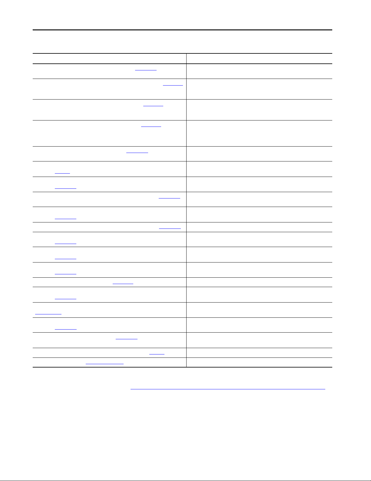
This table contains the changes that are made to this revision.
Top ic Pag e
Added firmware revision 33.051 219, 224
In this publication, ‘ControlLogix Redundancy’ refers to
ControlLogix 5570/5560 Redundancy.
This publication provides this information specific to redundancy systems:
• Design and planning considerations
•Installation procedures
• Configuration procedures
• Maintenance and troubleshooting methods
This publication is designed for use by anyone responsible for planning and
implementing a ControlLogix® redundancy system:
• Application engineers
• Control engineers
• Instrumentation technicians
The contents of this publication are for anyone who already has an understanding
of Logix 5000™ control systems, programming techniques, and communication
networks.
Additional Resources
These documents contain additional information concerning related products
from Rockwell Automation.
Table 1 - Additional Documentation
Resource Description
1715 Redundant I/O System Specifications Technical Data, publication 1715-TD001 Contains specifications on a Redundant I/O system.
1756 ControlLogix Controllers Technical Data, publication 1756-TD001 Contains specifications on ControlLogix controllers and redundancy modules.
ControlLogix 5580 Redundant Controller User Manual, publication 1756-UM015
High Availability Systems Reference Manual, publication HIGHAV-RM002
ControlFL ASH Firmware Upgrade Software User Manual, publication 1756-UM105
ControlFLASH Plus Quick Start Guide, publication CFP-QS001C-EN-E
ControlLogix Redundancy Update and Module Replacement Guidelines Reference Manual,
publication 1756-RM010
ControlLogix System Selection Guide, publication 1756-SG001
ControlLogix System User Manual, publication 1756-UM001
Describes how to install, configure, program, operate, and troubleshoot
a ControlLogix® 5580 redundancy system..
Provides information to help design and plan high availability systems.
Describes how to use the ControlFLASH™ software to upgrade device firmware.
Describes how to use the ControlFLASH Plus™ software to upgrade device firmware.
Provides instructions for replacing modules or updating firmware in a powered-up
redundancy system.
Provides information on how to select components for a ControlLogix system.
Contains information on how to install, configure, program, and operate a
ControlLogix system.
Rockwell Automation Publication 1756-UM535I-EN-P - October 2020 9
Page 10
Preface
Table 1 - Additional Documentation
Resource Description
ControlNet Network Configuration User Manual, publication CNET-UM001 Describes ControlNet® modules and how to use ControlNet modules with a Logix
EtherNet/IP Parallel Redundancy Protocol Application Technique, publication ENET-AT006 Describes how to configure a Parallel Redundancy Protocol (PRP) network with the
EtherNet/IP Device Level Ring Application Technique, publication ENET-AT007 Describes how to install, configure, and maintain linear and Device Level Ring (DLR)
EtherNet/IP Socket Interface Application Technique, publication ENET-AT002 Logix 5000Describes the socket interface that you can use to program MSG
EtherNet/IP Network Devices User Manual, publication ENET-UM006
Integrated Architecture and CIP Sync Configuration Application Technique,
publication IA-AT003
Logix 5000 Controllers Common Procedures Programming Manual,
publication 1756-PM001
Logix 5000 Controllers General Instructions Reference Manual, publication 1756-RM003
Logix 5000 Controllers Information and Status Programming Manual,
publication 1756-PM015
Logix 5000 Controllers I/O and Tag Data Programming Manual, publication 1756-PM004 Provides information on how to access I/O and tag data in Logix 5000 controllers.
Logix 5000 Controllers Major, Minor, and I/O Faults Programming Manual,
publication 1756-PM014
Logix 5000 Controllers Nonvolatile Memory Card Programming Manual,
publication 1756-PM017
Logix 5000 Produced and Consumed Tags Programming Manual,
publication 1756-PM011
Logix 5000 Controllers Quick Start, publication 1756-QS001
Logix 5000 Controllers Tasks, Programs, and Routines Programming Manual,
publication 1756-PM005
PlantPAx DCS Configuration and Implementation User Manual, publication
PROCES-UM100
Using ControlLogix in SIL 2 Applications Safety Reference Manual,
publication 1756-RM001
Redundant I/O System User Manual, publication 1715-UM001
Industrial Automation Wiring and Grounding Guidelines, publication 1770-4.1
Product Certifications website, rok.auto/certifications
5000 controller.
1756-EN2TP EtherNet/IP™ communication module and a Stratix® 5400 or 5410
switch.
networks that use Rockwell Automation® EtherNet/IP devices with embedded switch
technology.
instructions to communicate bet ween a Logix 5000 controller via an EtherNet/IP
module and Ethernet devices that do not support the EtherNet/IP application
protocol.
Describes how to use EtherNet/IP communication modules with your Logix 5000
controller and communicate with various devices on the Ethernet network.
Provides an explanation of CIP Sync™ technology and how you can synchronize clocks
within the Rockwell Automation Integrated Architecture®.
Provides links to a collection of programming manuals that describe how to use
procedures that are common to all Logix 5000 controllers projects.
This manual provides details about each available instruction for a Logix-based
controller.
Describes how Logix 5000 controllers use connections with other devices.
Describes how to monitor and handle major and minor controller faults.
Provides information on how to access and use a memory card in Logix 5000
controllers.
Provides information to produce and consume system-shared tags and produce a
large array with a Logix 5000 controller.
Provides information to program and maintain Logix 5000 controllers.
Provides information to configure controller tasks and the programs and routines for
the proper execution of these tasks.
Elaborates on the application rules that are required to configure a PlantPAx® system.
Provides safety-related information specific to the use of ControlLogix modules in SIL
2 systems.
Contains information on how to install, configure, program, operate, and
troubleshoot a Redundant I/O system.
Provides general guidelines for installing a Rockwell Automation industrial system.
Provides declarations of conformity, certificates, and other certification details.
You can view or download publications at
http://www.rockwellautomation.com/global/literature-library/overview.page
To order paper copies of technical documentation, contact your local
Allen-Bradley distributor or Rockwell Automation sales representative.
10 Rockwell Automation Publication 1756-UM535I-EN-P - October 2020
.
Page 11

Chapter 1
About ControlLogix Redundancy Systems
Top ic Pa ge
Features of the ControlLogix Redundancy System 12
Redundancy System Components 13
Redundancy System Operations 15
Restrictions 19
IMPORTANT In this publication, ‘ControlLogix Redundancy’ refers to
ControlLogix 5570/5560 Redundancy.
The ControlLogix® Redundancy System is a system that provides greater
availability. The system has greater availability because it uses a redundant chassis
pair. The redundant chassis pair maintains process operation when events, such as
a fault on a controller, occur that stop process operation on
non-redundant systems.
The redundant chassis pair includes two synchronized ControlLogix chassis with
identically specific components in each. For example, one redundancy module
and at least one ControlNet® or EtherNet/IP™ communication module are
required.
Controllers are typically used in redundancy systems, but are not required if your
application only requires communication redundancy. Your application operates
from a primary chassis, but can switch over to the secondary chassis and
components if necessary.
Rockwell Automation Publication 1756-UM535I-EN-P - October 2020 11
Page 12

Chapter 1 About ControlLogix Redundancy Systems
Features of the ControlLogix Redundancy System
The software and hardware components that are required to configure and use a
ControlLogix redundancy system provide these features:
• Redundancy module speeds of up to 1000 Mbps when using a 1756-RM2
module with another 1756-RM2 module. Redundancy module speeds up
to 100 Mbps when using a 1756-RM/A with another 1756-RM/A
module, and a 1756-RM/B module with another 1756-RM/B module.
• The 1756-RM2 and 1756-RM2XT modules are interference-free
regarding safety functions and can be used in ControlLogix SIL 2
applications. See the Using ControlLogix in SIL 2 Applications Safety
Reference Manual, publication 1756-RM001
• Redundant fiber ports for crossloading; no single point of failure of a fiber
cable.
• Plug-and-play-style commissioning and configuration that does not
require extensive programming.
• ControlNet and EtherNet/IP network options for the redundant
chassis pair.
• Easy-to-use, fiber-optic communication cable that connects redundant
chassis pairs. Use the same cable for the 1756-RM2 or 1756-RM/B
modules.
• Simple redundant controller configuration by using a checkbox in the
Controller Properties dialog box in the Studio 5000 Automation &
Engineering Design Environment® programming software.
• A redundancy system ready to accept commands and monitor the
redundant system states after basic installation, connection, and powerup.
• Switchovers occur as fast as 20 ms.
• Support for FactoryTalk® applications for Ethernet communication
modules including, but not limited to:
– FactoryTalk Alarms and Events
– FactoryTalk Batch
– FactoryTalk PhaseManager™
• Instruction Based Alarms (IBA) considerations:
– 5560 supports up to 250 IBA's with 250 burst
– 5570 supports up to 500 IBA's with 250 burst
– For more information see the Knowledgebase Article, ALMA/ALMD
instructions limits
• Support for CIP Sync™ technology over an EtherNet/IP network to
establish time coordination across the redundant system.
• Access to remote I/O modules over an EtherNet/IP network.
• Access to 1715 Redundant I/O systems over an EtherNet/IP network.
• Ethernet socket support.
• Support for PhaseManager.
• Supports PRP topologies. See the EtherNet/IP Parallel Redundancy
Protocol Application Technique, publication ENET-AT006
• Supports DLR and topologies. See the EtherNet/IP Device Level Ring
Application Technique, publication ENET-AT007
.
.
.
12 Rockwell Automation Publication 1756-UM535I-EN-P - October 2020
Page 13

About ControlLogix Redundancy Systems Chapter 1
Features Not Supported
•Any motion feature
• Any SIL 3 functional safety feature within the redundancy controllers
•Firmware Supervisor
• SequenceManager™
•Event Tasks
IMPORTANT For Ethernet modules, signed and unsigned firmware are available. Signed
modules provide the assurance that only validated firmware can be upgraded
into a module.
Signed and unsigned firmware:
• Both signed and unsigned firmware are available.
• Product is shipped with unsigned firmware. To obtain signed firmware,
you must upgrade the firmware for your product.
• To obtain signed and unsigned firmware, go to
http://www.rockwellautomation.com/global/support/firmware/
overview.page.
• Once signed firmware is installed, subsequent firmware updates must be
signed also.
There are no functional/feature differences between signed and unsigned
communication modules.
Redundancy System Components
Communication between a redundant chassis pair that includes matching
components makes redundancy possible.
Each chassis in the redundant chassis pair contains these ControlLogix
components:
• One ControlLogix power supply - Required
• One ControlLogix redundancy module - Required
• Redundancy modules link the redundant chassis pair to monitor events in
each of chassis and initiate system responses as required.
• At least one ControlLogix ControlNet or EtherNet/IP communication
module - up to seven, optional (any combination)
• At least one controller - up to two controllers in the same family, optional
If the chassis is used as a redundant gateway, then a controller is not
required.
In addition, redundant chassis are connected to other components outside the
redundant chassis pair, for example, remote I/O chassis or human machine
interfaces (HMIs).
For more information about components you can use in a redundancy system, see
Chapter 2
, Design a ControlLogix Redundancy System on page 21.
Rockwell Automation Publication 1756-UM535I-EN-P - October 2020 13
Page 14

Chapter 1 About ControlLogix Redundancy Systems
I/O Modules in Redundancy Systems
In a redundancy system, you can only use I/O modules in a remote chassis. You
cannot use I/O modules in the redundant chassis pair.
This table describes differences in network use for I/O in redundancy systems.
Remote I/O Module Placement Available with Redundancy System, Revision 19 and Later Available with Redundancy System, Revision 16 or Earlier
EtherNet/IP I/O network x -
ControlNet network x x
DeviceNet® network
Data Highway Plus™
Universal remote I/O
(1) In a redundancy system, you can access remote I/O modules on this network only via a ControlNet or EtherNet/IP network bridge.
(2) 1756-DHRIO module must be used with a channel configured for RIO.
(1)
(1)
(1)(2)
xx
xx
xx
For more information on how to use remote and 1715 redundant I/O over an
Ethernet network, see I/O Placement on page 36
User Manual, publication 1715-UM001
.
and the Redundant I/O System
14 Rockwell Automation Publication 1756-UM535I-EN-P - October 2020
Page 15

About ControlLogix Redundancy Systems Chapter 1
Redundancy System Operations
Once the redundancy modules in the redundant chassis pair are connected and
powered, they determine which chassis is the primary chassis and which is the
secondary chassis.
The redundancy modules in both the primary and secondary chassis monitor
events that occur in each of the redundant chassis. If certain faults occur in the
primary chassis, the redundancy modules execute a switchover to the unfaulted,
secondary chassis.
System Qualification and Synchronization
When the redundant system is first started, the redundancy modules run checks
on the redundant chassis. These checks determine if the chassis contain the
appropriate modules and firmware to establish a redundant system. This stage of
checks is referred to as qualification.
After the redundancy modules complete qualification, synchronization can take
place. Synchronization is a state in which the redundancy modules execute these
tasks:
• Verify that the connection between redundancy modules is ready to
facilitate a switchover
• Verify that the redundant chassis continue to meet qualification
requirements
• Synchronize the data between the redundant controllers, also called
crossloading
This data is crossloaded:
–Updated tag values
–Forced values
–Online edits
–Other project information
Synchronization always takes place immediately following qualification. Also,
depending on your system configuration, synchronization takes place at the end
of each program that is run within the controller project, or at other intervals that
you specify.
Rockwell Automation Publication 1756-UM535I-EN-P - October 2020 15
Page 16

Chapter 1 About ControlLogix Redundancy Systems
Switchovers
During redundant system operation, if certain conditions occur on the primary
chassis, primary control is switched to the secondary chassis. These conditions
cause a switchover:
•Loss of power
• Major fault on the controller
• Removal or insertion of any module
• Failure of any module
• Damage to a ControlNet cable or tap - This event only causes a switchover
if it results in the ControlNet communication module transition to a
lonely state, that is, the module does not see any devices on the network.
• Loss of an EtherNet/IP connection - This event only causes a switchover if
it results in the EtherNet/IP communication module transition to a lonely
state, that is, the module does not see any devices on the network.
• A program-prompted command to switchover
• A command that is issued via the Redundancy Module Configuration
To ol (R M CT )
After a switchover occurs, the new primary controller continues to execute
programs, which begin with the highest-priority task that had been executing on
the previous primary controller.
For more information about how tasks execute after a switchover, see Crossloads,
Synchronization, and Switchovers on page 116.
Your application can require some programming considerations and potential
changes to accommodate a switchover. For more information on these
considerations, see Chapter 7
, Program the Redundant Controller on page 111.
IMPORTANT During a switchover of the fiber channels of the 1756-RM2 module, scan
time encounters a delay of ~10 ms; however, the chassis always remains
synched.
16 Rockwell Automation Publication 1756-UM535I-EN-P - October 2020
Page 17

About ControlLogix Redundancy Systems Chapter 1
Data Server Communication Recovery Time Reduction During a Switchover
Brief communication interruption occurs between FactoryTalk Linx software
and the redundant chassis pair when a switchover occurs. After the switchover is
complete, communication resumes automatically.
Data server communication recovery time is the time during a switchover from
primary to secondary, when tag data from the controller is unavailable for reading
or writing. Data server communication recovery time applies to any software that
uses tag data, such as HMI displays, data loggers, alarms systems, or historians.
Data server communication recovery time reduction is important to increase the
availability of the system.
IMPORTANT • Prior to firmware revision 30.051, the communication delays apply only
when communication is exclusively over EtherNet/IP networks.
• With fir mware revision 30.051 or later, the communication delays apply to
both EtherNet/IP and ControlNet networks.
IMPORTANT FactoryTalk Linx software is part of FactoryTalk Services, which has been
releasing a series of Service Releases (SRs) that are backward compatible
with any CPR 9 products. Existing and new users who are using FactoryTalk
View version 5.0 (CPR9) or later can use the data server communication
recovery time feature.
As of revision 31.052, the communication delays over Ethernet during a
switchover event have been reduced significantly. When you configure the
connection between a FactoryTalk Linx data server, and a redundant
ControlLogix controller, you can configure redundant shortcut paths to the
primary and secondary controllers. These shortcut paths help reduce data server
communication recovery time that occurs during a redundancy switchover.
The following are required to take advantage of this:
• A dedicated pair of ControlLogix Communication Modules with
firmware revision 11.001 or later (1756-EN2TP, 1756-EN2TR,
1756-EN2T), that do not swap IP addresses. See Do Not Use IP Address
Swapping on page 66.
• ControlLogix 5570 redundancy controllers with redundancy firmware
revision 31.052 or later
• FactoryTalk Linx 6.00 with the FactoryTalk Linx patch available from
Rockwell Automation Knowledgebase Article Patch: FactoryTalk Linx
6.00 patch required to support ControlLogix V31.05 Redundancy, or later
versions of FactoryTalk Linx.
Rockwell Automation Publication 1756-UM535I-EN-P - October 2020 17
Page 18

Chapter 1 About ControlLogix Redundancy Systems
• Redundant ControlLogix Controller shortcut type in FactoryTalk Linx
that points to the Primary and Secondary controllers through the
communication modules, without swapping IP addresses. For information
on shortcuts in FactoryTalk Linx, see the FactoryTalk Linx Getting Results
Guide, publication LNXENT-GR001
.
18 Rockwell Automation Publication 1756-UM535I-EN-P - October 2020
Page 19

About ControlLogix Redundancy Systems Chapter 1
Some communication delays can occur during qualification. The existence and
duration of these delays depend on:
• Quantity and types of tags on scan in FactoryTalk Linx software
• Client screen and tag update rates (e.g. FactoryTalk Live Data/FactoryTalk
Historian)
• Number of data subscribers (i.e. FactoryTalk Alarms and Events,
FactoryTalk Batch)
• Size of the application in the redundant controller
• Controller loading, which includes the following:
• Number of tasks and scan rates (assumes no continuous task)
• Number of programs
•Memory usage
• Null task percentage available
•Network traffic
Restrictions
There are restrictions that you must consider when using a redundancy system.
Most of these restrictions apply to all redundancy system revisions. Exceptions
are noted:
• See the release notes of the redundancy bundles for compatible products,
versions, and revisions
• The redundant controller program cannot contain these tasks:
–Event tasks
– Inhibited tasks
For recommendations and requirements that are related to programming
the redundant controller, see Program the Redundant Controller on
page 111.
• You cannot use the Match Project to Controller feature available in Studio
5000 Logix Designer® in a redundancy system.
• You cannot use motion in a redundant controller program.
• You cannot use SequenceManager.
• You cannot use consumed unicast connections in a redundancy system. If
you attempt to use consumed unicast connections, disqualification occurs
and qualification of an unsynchronized redundant chassis pair is not
allowed. You can use produced unicast connections that remote consumers
consume.
• Outputs controlled by specific instructions are not guaranteed to maintain
a bumpless transition during a switchover. Due to this, it is recommended
to avoid using the following instructions within a redundancy system:
–IOT
–HMIBC
• You can use a maximum of two controllers of the same family, and seven
ControlNet or EtherNet/IP communication modules in each chassis of a
redundant chassis pair.
• You can execute the tasks that were supported previously in a redundancy
system, revision 19.052 or greater.
Rockwell Automation Publication 1756-UM535I-EN-P - October 2020 19
Page 20
Chapter 1 About ControlLogix Redundancy Systems
01 12 13 24
Catalyst 9300 24S
NETWORK MODULE
C9300-NM-2Q
40G 1
40G 2
01 12 13 24
Catalyst 9300 24S
NETWORK MODULE
C9300-NM-2Q
40G 1
40G 2
01 12 13 24
Catalyst 9300 24S
NETWORK MODULE
C9300-NM-2Q
40G 1
40G 2
01 12 13 24
Catalyst 9300 24S
NETWORK MODULE
C9300-NM-2Q
40G 1
40G 2
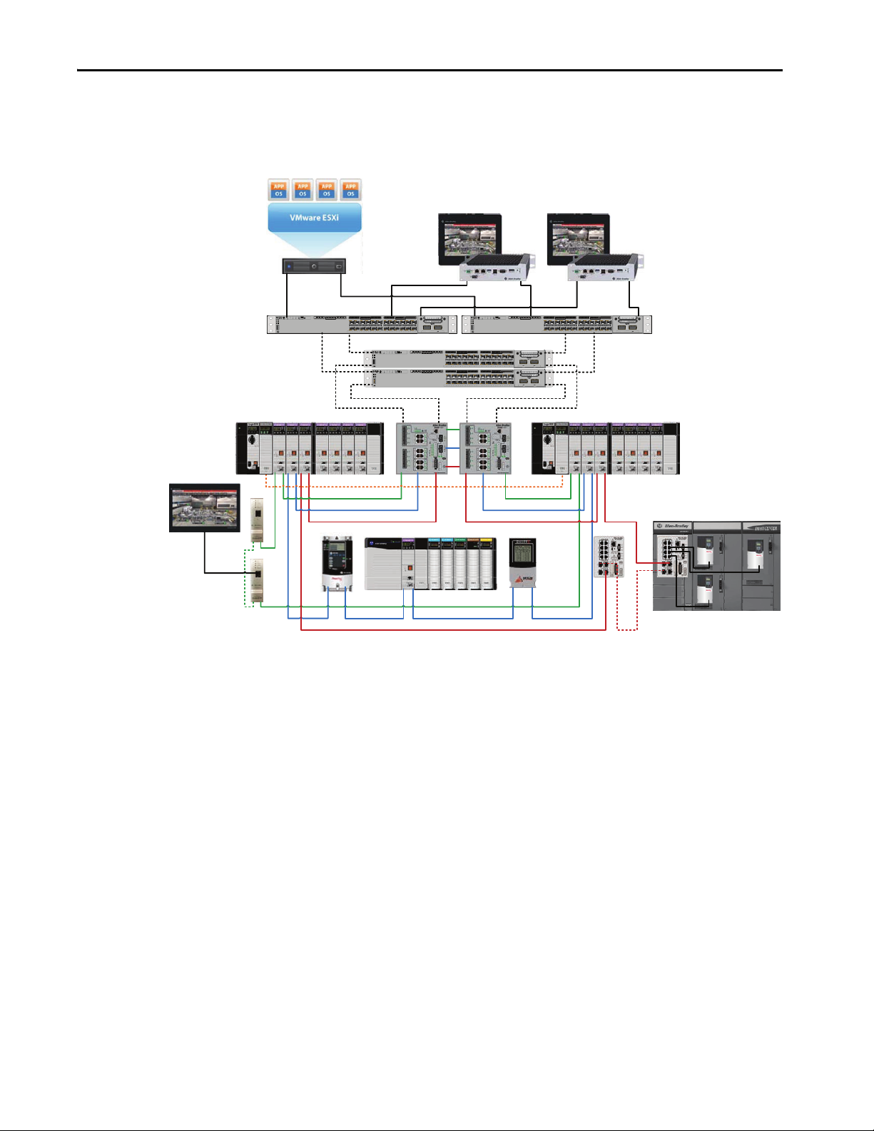
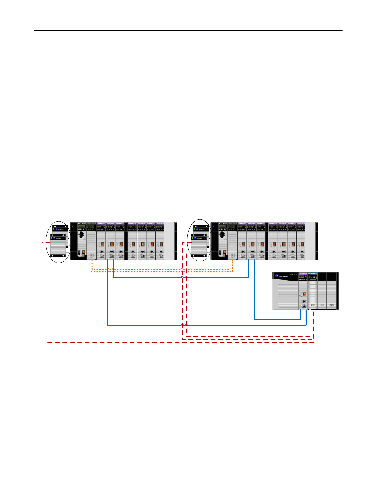
This graphic shows an example ControlLogix redundancy system,
revision 19.053 or greater, which uses EtherNet/IP networks.
Figure 1 - Example ControlLogix Redundancy System using an EtherNet/IP Network
20 Rockwell Automation Publication 1756-UM535I-EN-P - October 2020
Page 21

Chapter 2
Design a ControlLogix Redundancy System
Top ic Pa ge
Redundant Chassis 21
Controllers in Redundant Chassis 22
EtherNet/IP Networks with Redundant Systems 28
ControlNet Networks with Redundant Systems 30
Other Communication Networks 34
I/O Placement 36
Using HMI 38
Optional Software 41
This chapter explains how to use the required and optional components to design
a redundancy system.
Redundant Chassis
IMPORTANT There are module series level, firmware revision, and software version
requirements for redundancy systems.
For more information on these module series level, firmware revision, and
version requirements, see the current release notes at:
http://www.rockwellautomation.com/global/literature-library/
overview.page
You can use any ControlLogix® or ControlLogix-XT™ chassis in a redundant
chassis pair as long as the two chassis that are used are the same size. For example,
if the primary chassis in your redundant chassis pair uses a 1756-A4 chassis, the
secondary chassis must use a 1756-A4 chassis.
TIP When using 1756-L72, 1756-L73, 1756-L74, or 1756-L75 Redundant
controllers in your system, you must use firmware revision 19.053 or greater.
When using a 1756-L71 Redundant controller, you must use firmware
20.054 or greater.
Rockwell Automation Publication 1756-UM535I-EN-P - October 2020 21
Page 22
Chapter 2 Design a ControlLogix Redundancy System
CH2 CH1 OK
CH2 CH1 OK
1756-L64
1756-L64
01 2 3 0 1 23
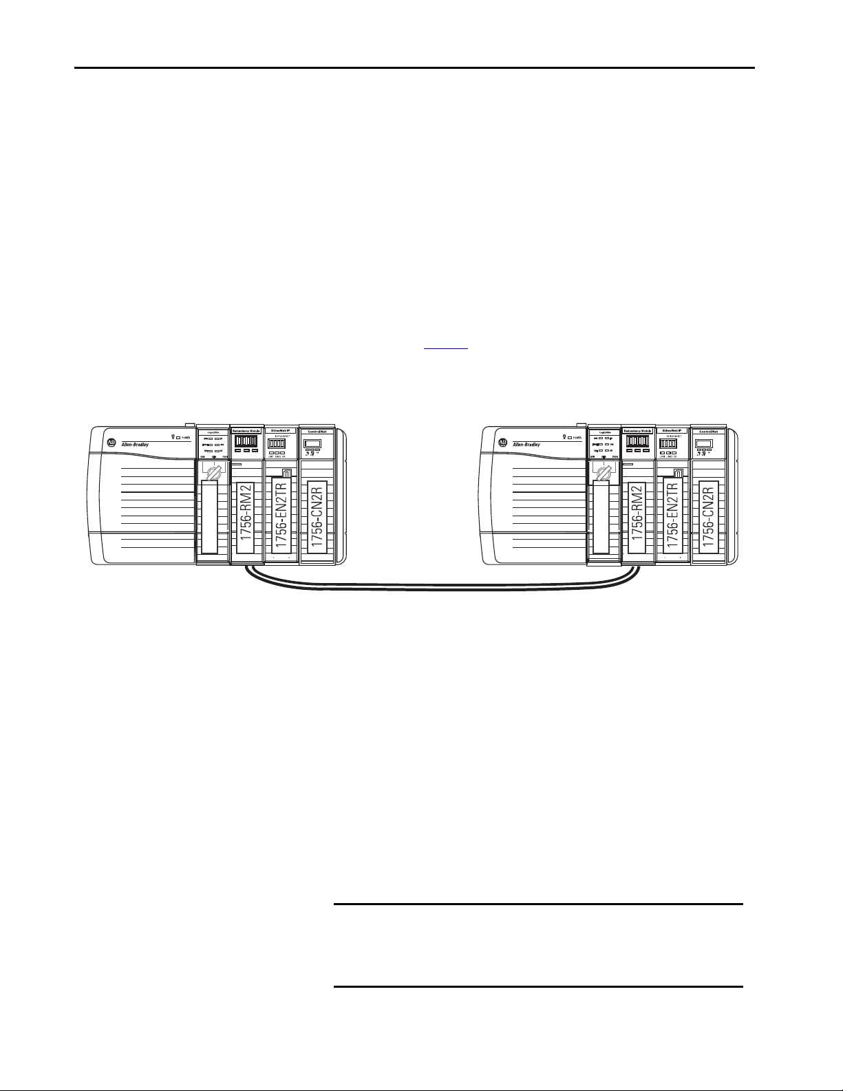
Redundant Chassis Configuration Requirements
These configuration parameters must match for the components in a redundant
chassis pair during normal system operation:
•Module type
• Chassis size
• Slot placement
•Firmware revision
•Series level. See page 25
Figure 2 - Example of Redundant Chassis Pair
Controllers in Redundant Chassis
Remember these points when you place controllers in the redundant chassis pair:
• Controllers are typically included, but not required, in redundancy
systems. If you have a redundancy system without controllers, you have
only a redundant gateway rack.
• You can place up to two controllers in the same chassis. When you use two
controllers in the same chassis, they must be of the same product family.
The series of the controller in the primary and secondary chassis do not
need to match.
For example, you cannot place a ControlLogix 5560 controller and a
ControlLogix 5570 controller in the same chassis.
IMPORTANT When using a ControlLogix redundancy system, revision 16.081 or
earlier, you cannot use two 1756-L64 controllers in the same
chassis. You can, however, use a 1756-L64 controller in the same
chassis as a 1756-L61, 1756-L62, or 1756-L63 controller.
22 Rockwell Automation Publication 1756-UM535I-EN-P - October 2020
Page 23

Design a ControlLogix Redundancy System Chapter 2
• You can use different catalog numbers from the same product family in the
same chassis. For example, you can use two ControlLogix 5560 controllers
in a chassis.
• Each ControlLogix 5560/5570 controller must have enough data memory
to store twice the amount of tag data that is associated with a redundant
controller project.
TIP ControlLogix 5580 controllers that are enabled for redundancy do not have
memory constraints.ControlLogix 5580 controllers that are enabled for
redundancy experience no reduction in memory from a standard use
ControlLogix 5580 controller.
• Each controller must have enough I/O memory to store twice the amount
of I/O memory used. To check the I/O memory that is used and available,
access the Memory tab of the Controller Properties dialog box in the
programming software.
For more information about data and I/O memory, see the
Knowledgebase Article Understanding ControlLogix Redundancy Memory
Usage.
• When you use the redundancy system update (RSU) feature to update a
redundancy system while the system continues operation, the updated
controllers must provide the same or greater memory than the existing
controllers.
This table describes the controllers to which you can upgrade, based on the
existing controller that is used, when using RSU.
Existing New Controller
1756-L61 1756-L61, 1756-L62, 1756-L63, 1756-L64, 1756-L65
1756-L62 1756-L62, 1756-L63, 1756-L64, 1756-L65
1756-L63 1756-L63, 1756-L64, 1756-L65
1756-L64 1756-L64, 1756-L65
1756-L65 1756-L65
1756-L71 1756-L71, 1756-L72, 1756-L73, 1756-L74, 1756-L75
1756-L72 1756-L72, 1756-L73, 1756-L74, 1756-L75
1756-L73 1756-L73, 1756-L74, 1756-L75
1756-L74 1756-L74, 1756-L75
1756-L75 1756-L75
Differences in controller types between chassis can exist only during the
system upgrade process. When you complete the system upgrade, the
controllers in the redundant chassis pair must match for the system to
synchronize.
Rockwell Automation Publication 1756-UM535I-EN-P - October 2020 23
Page 24

Chapter 2 Design a ControlLogix Redundancy System
Plan for Controller Connections
Consider these conditions when you plan controller connection use:
• ControlLogix 5560 controllers provide 250 total connections.
• ControlLogix 5570 controllers provide 500 total connections.
If you use the redundant controller at, or very near the connection limits, you can
experience difficulty synchronizing your chassis.
Redundancy Modules in Redundant Chassis
Two redundancy modules, one in each chassis of the redundant chassis pair,
jointly supervise the control system operating states and transitions, which
establishes the framework for system redundancy. This bridge between chassis
facilitates the exchange of control data and synchronization of operations.
The redundancy modules let you commission the redundant system in a plugand-play manner without any programming. You connect a redundancy module
pair with the default configuration in the redundant chassis pair and configure
the redundant system.
You can establish redundancy between chassis in either of these manners:
• Insert a redundancy module pair into two powered chassis that contain
redundancy-compliant components and redundancy-enabled application
programs, and then connect the redundancy modules.
• Insert and connect the redundancy modules in two chassis and then insert
redundancy-compliant components into each chassis.
IMPORTANT You are not required to develop any programming to migrate from a non-
redundant to a redundancy system if your application meets these
conditions:
• Your application meets the points that are listed in Restrictions on
page 19.
• The controller properties dialog box in your project has Redundancy
enabled.
Once the redundant chassis pair contains all desired components and is powered,
no further tasks are required in the redundancy modules to activate system
redundancy. The redundancy modules automatically determine the operational
state of each of the chassis pair and are ready to accept commands and provide
system monitoring.
24 Rockwell Automation Publication 1756-UM535I-EN-P - October 2020
Page 25

Design a ControlLogix Redundancy System Chapter 2
Communication Modules in Redundant Chassis
Remember these points when placing ControlLogix ControlNet® and
EtherNet/IP™ communication modules in the redundant chassis pair:
• You must use enhanced communication modules in redundancy systems.
Enhanced communication modules contain a ‘2’ in their catalog number.
For example, the 1756-EN2T module.
•Standard ControlNet and EtherNet/IP communication modules are not
supported. Standard communication modules contain a 'B' in their catalog
number. For example, the 1756-ENBT module.
• You can use the 1756-EN2TR module only with a redundancy system,
revision 19.052 or later.
• You can use the 1756-EN2F module only with a redundancy system,
revision 20.054 or later.
• You can use the 1756-EN2TP module only with a redundancy system,
revision 31.052 or later.
• You can use any combination of up to seven enhanced communication
modules in each redundant chassis.
• If you use a ControlNet network in your redundant chassis pair, you must
have two ControlNet communication modules outside the redundant
chassis pair. When you assign node address numbers, assign the lowest
node number address to a ControlNet communication module outside the
redundant chassis pair.
For more information, see Use at Least Four ControlNet Network Nodes
on page 30 through Assign Lowest Node Numbers to Remote ControlNet
Modules on page 31.
• You cannot use Series A ControlNet communication modules in a
redundancy system.
• The Series for EtherNet/IP communication modules is not required to
match in a partnered set. However, the firmware levels must be the same in
a partnered set. Also, if your application requires a feature specific to a
module series level, you must use the same series level for each module in a
partnered set.
For example, only the 1756-EN2T/C communication module only offers
the double-data rate (DDR) feature. You must use 1756-EN2T/C
modules in each chassis of the redundant chassis pair to use DDR.
Rockwell Automation Publication 1756-UM535I-EN-P - October 2020 25
Page 26

Chapter 2 Design a ControlLogix Redundancy System
• Do not use the USB ports of communication modules to access the
redundant system network while the system is running, that is, online. Use
of the USB ports while online can result in a loss of communication after a
switchover.
Plan for Communication Module Connections
A CIP™ connection is a point-to-point communication mechanism that is used
to transfer data between a producer and a consumer. These mechanisms are
examples of CIP connections:
• Logix 5000™ controller message transfer to Logix 5000 controller
•I/O or produced tag
• Program upload
• RSLinx® DDE/OPC client
• PanelView™ polling of a Logix 5000 controller
ControlLogix ControlNet communication modules provide 131 total CIP
connections. Consider these points when using CIP connections with
ControlLogix ControlNet communication modules:
• Three of the 131 CIP connections are reserved for redundancy. The three
redundant-system CIP connections always appear to be in use, even when
no connections are open.
• You can use the remaining 128 CIP connections in any manner that your
application requires, such as the examples listed previously.
ControlLogix EtherNet/IP communication modules provide 259 total CIP
connections. Consider these points when using CIP connections with
ControlLogix EtherNet/IP communication modules:
• Three of the 259 CIP connections are reserved for redundancy.
• You can use the remaining 256 connections in any manner that your
application requires, such as the examples listed previously.
26 Rockwell Automation Publication 1756-UM535I-EN-P - October 2020
Page 27
Design a ControlLogix Redundancy System Chapter 2
1756-PA75R or 1756-PB75R Power Supplies
Annunciator Wiring (optional)
Power Supplies and Redundant Power Supplies in Redundancy Systems
Redundancy systems can use standard power supplies. You can choose to use
redundant power supplies to maintain power to a ControlLogix chassis if one of
the supplies loses power. Use these hardware components to connect redundant
power supplies:
• Two redundant power supplies for each chassis
• One 1756-PSCA chassis adapter for each redundant chassis
• Two 1756-CPR cables for each redundant chassis to connect the power
supplies to the 1756-PSCA adapter
• Optional, user-supplied annunciator wiring to connect the power supplies
to remote input modules
Figure 3 - Redundant Power Supplies with Redundant Chassis
For more information about redundant power supplies, see the ControlLogix
System Selection Guide, publication 1756-SG001
Rockwell Automation Publication 1756-UM535I-EN-P - October 2020 27
.
Page 28

Chapter 2 Design a ControlLogix Redundancy System
EtherNet/IP Networks with Redundant Systems
The use of EtherNet/IP networks in a redundancy system is primarily dependent
on your system revision.
IMPORTANT A remote chassis can be accessed over an EtherNet/IP network by using any
EtherNet/IP module that works in a non-redundant chassis with no
additional firmware requirement with the following exception. If the remote
chassis contains a controller that consumes a tag that is produced in the
redundant chassis pair, it can only consume the tag with the required
firmware revisions.
For more information on how to use an EtherNet/IP network in your
redundancy system, see Configure the EtherNet/IP Network on page 65
.
Unicast Functionality
Redundancy systems support unicast produced tags. Unicast consumed tags are
not supported in redundancy systems. Unicast I/O is not supported in a
redundancy system.
Possible Communication Delays on EtherNet/IP and ControlNet Networks
The connection between a component and the redundant chassis pair can
experience brief communication delays during a switchover. After the switchover
is complete, communication resumes automatically.
These connection types can experience the communication delay when the
switchover occurs:
• HMI to redundant chassis pair
• FactoryTalk® Batch server to redundant chassis pair
• FactoryTalk Alarms and Events Service to redundant chassis pair
IMPORTANT • Prior to firmware revision 30.051, the communication delays apply only
when communication is exclusively over EtherNet/IP networks.
• With fir mware revision 30.051 or later, the communication delays apply to
both EtherNet/IP and ControlNet networks.
28 Rockwell Automation Publication 1756-UM535I-EN-P - October 2020
Page 29
Design a ControlLogix Redundancy System Chapter 2
ControlNe t
EtherNet/IP
HMI
Redundant Chassis Pair
Bridge from an EtherNet/IP Network to a ControlNet Network
Bridge from an EtherNet/IP network to a ControlNet network if you must
maintain the connection between the component and a redundant chassis pair
during a switchover.
IMPORTANT You can bridge from an EtherNet/IP network to a ControlNet network to
maintain the connection between the component and a redundant chassis
only in redundancy firmware revisions prior to revision 30.051.
I/O connections are not supported in any bridge configurations in any
version.
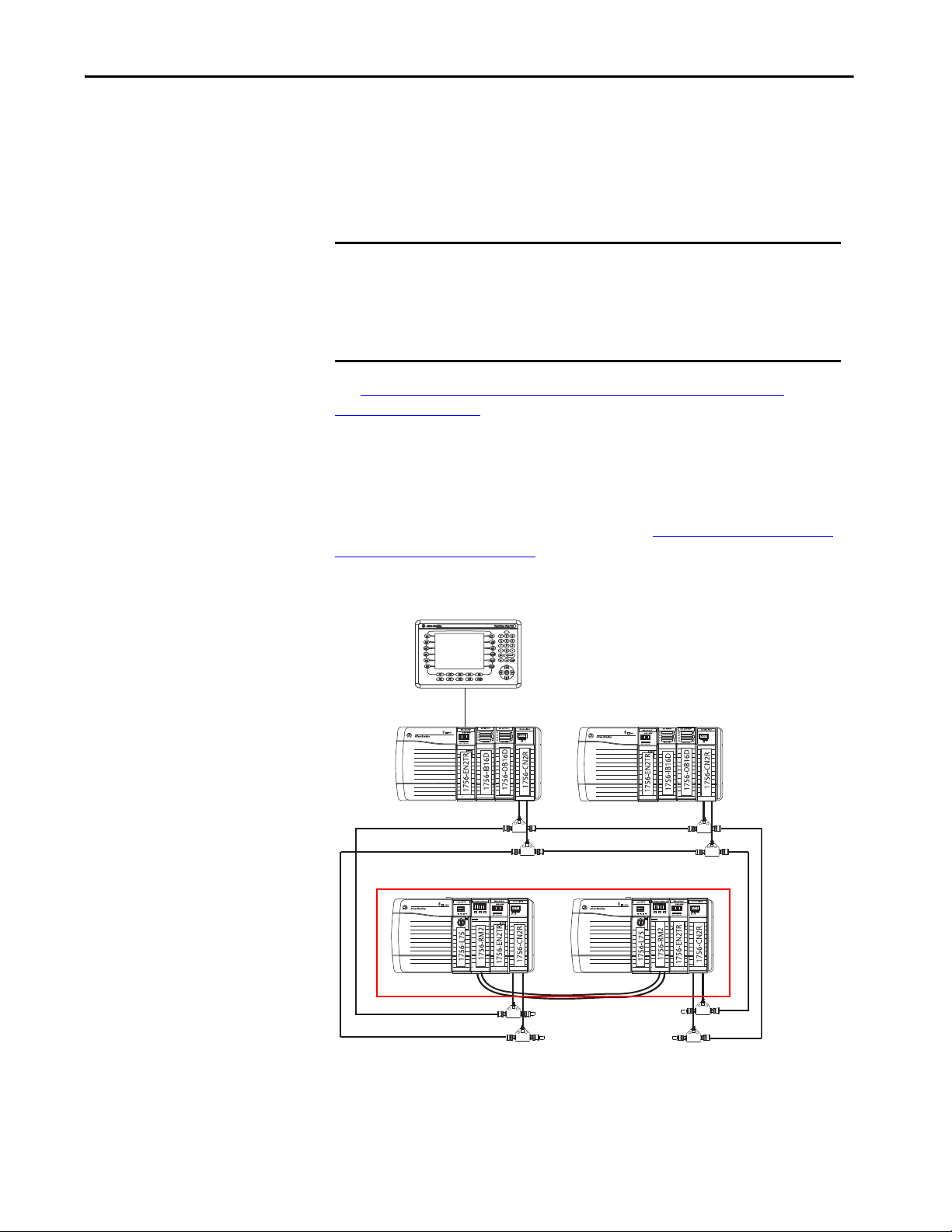
See Data Server Communication Recovery Time Reduction During a
Switchover on page 17.
This example graphic shows the recommended method to connect an HMI to a
redundant chassis pair if connection drops are a concern in your application. In
this graphic, the remote chassis contains I/O modules and the EtherNet/IP and
ControlNet communication modules. The I/O modules are not required and are
shown for example only. For all requirements, see ControlNet Networks with
Redundant Systems on page 30.
Figure 4 - Configuration Used to Eliminate Communication Delays on Switchover
CH2 CH1 OK
CH2 CH1 OK
Rockwell Automation Publication 1756-UM535I-EN-P - October 2020 29
Page 30

Chapter 2 Design a ControlLogix Redundancy System
ControlNet Networks with Redundant Systems
ControlNet networks are used to connect redundant controller chassis to remote
I/O and to other devices in the system.
IMPORTANT A remote chassis can be accessed over a ControlNet network that uses any
ControlNet module that works in a non-redundant chassis with no
additional firmware requirement.
ControlNet Network Requirements
If you use a ControlNet network in your redundancy system, you must
consider the following:
• Use at Least Four ControlNet Network Nodes
• Assign Lowest Node Numbers to Remote ControlNet Modules
• Set Partnered ControlNet Module Switches to the Same Address
• Reserve Consecutive Node Addresses for Partner Modules
Use at Least Four ControlNet Network Nodes
With redundant systems, at least four ControlNet network nodes are required
per ControlNet network. This configuration is required because two or more
ControlNet nodes must be used with the two ControlNet modules that are used
in the redundant chassis. One of the two nodes outside of the redundant chassis
must be at a lower node address than the ControlNet modules in the redundant
chassis.
If your ControlNet uses fewer than four nodes, and a switchover occurs,
connections can drop and outputs connected to that node can change state
during the switchover.
You can include these ControlNet modules and redundant ControlNet nodes:
• ControlNet bridges in remote chassis
• Any other ControlNet devices on the ControlNet network
• A workstation running RSLinx Classic communication software that is
connected via a ControlNet network
For more information, see Knowledgebase Article ControlNet Network Keeper
and ControlLogix Redundancy.
30 Rockwell Automation Publication 1756-UM535I-EN-P - October 2020
Page 31

Design a ControlLogix Redundancy System Chapter 2
ControlNet Module Switches
Assign Lowest Node Numbers to Remote ControlNet Modules
Do not assign the lowest ControlNet node addresses to ControlNet modules in
the redundant chassis pair.
If you assign the lowest ControlNet node addresses to ControlNet modules in
the redundant chassis pair, you can experience these system behaviors:
• Upon a switchover, you can lose communication with I/O modules,
produced tags, and consumed tags.
• If you remove a ControlNet module from the redundant chassis, it can
result in lost communication with I/O modules, produced tags, and
consumed tags.
• If the entire system loses power, you can be required to cycle power to the
primary chassis to restore communication.
Set Partnered ControlNet Module Switches to the Same Address
Where ControlNet modules are used as partners in a redundant chassis pair, you
must set the node address switches to the same node address. The primary
ControlNet modules can be at even or odd node addresses.
For example, if partnered ControlNet modules are assigned to nodes 12 and 13
of the ControlNet network, set the node address switches of the modules to the
same address of 12.
Figure 5 - Example of Switch Address for Partnered ControlNet Modules
CH2 CH1 OK
1756-L64
CH2 CH1 OK
1756-L64
Rockwell Automation Publication 1756-UM535I-EN-P - October 2020 31
Page 32

Chapter 2 Design a ControlLogix Redundancy System
CH2 CH1 OK
CH2 CH1 OK
1756-L64
1756-L64
Node 12 Node 13
ControlNet Module Switches
Primary Chassis Secondary Chassis
Reserve Consecutive Node Addresses for Partner Modules
Where ControlNet modules are used as partners in redundant chassis, plan
consecutive node numbers for those partnered modules. Plan for consecutive
node addresses because the redundant system automatically assigns the
consecutive node address to the secondary ControlNet module.
For example, partnered ControlNet modules with address switches set at 12 are
assigned ControlNet node numbers 12 and 13 by the system.
TIP The primary chassis always assumes the lower of the two node
addresses.
Figure 6 - Example of Redundant ControlNet Modules at Consecutive Addresses
32 Rockwell Automation Publication 1756-UM535I-EN-P - October 2020
Page 33

Design a ControlLogix Redundancy System Chapter 2
Redundant ControlLogix Chassis with
1756-CN2R Modules
Redundant Trunk Lines
Work stati on wi th Con trolN et
Interface Card
Redundant ControlNet Media
The use of redundant ControlNet media helps to prevent a loss of
communication if a trunkline or tap is severed or disconnected. A system that
uses redundant ControlNet media uses these components:
• 1756-CN2R, series B or later, communication modules in each redundant
chassis
• ControlNet modules that are designed for redundant media at each
ControlNet node on the network
• Redundant trunk cabling
• Redundant tap connections for each ControlNet module connected
Figure 7 - Redundant ControlNet Media with Redundant ControlLogix Chassis
Rockwell Automation Publication 1756-UM535I-EN-P - October 2020 33
Page 34

Chapter 2 Design a ControlLogix Redundancy System
Secondary Chassis
Chassis Bridge from EtherNet/IP
to Remote I/O Net works
Primary Chassis
Other Communication Networks
You can use only EtherNet/IP and ControlNet networks, and corresponding
modules, in the local chassis for redundancy systems.
IMPORTANT Do not use the redundant chassis to bridge between networks. Bridging
through the redundant chassis to the same or different networks, or
routing messages through redundant chassis is not supported.
You can bridge to other communication networks outside of the redundant
chassis. You can bridge these networks via a remote chassis:
• DeviceNet
•Universal remote I/O
•Data Highway Plus™
Figure 8 - Example of Bridging to Remote I/O on Various Networks
34 Rockwell Automation Publication 1756-UM535I-EN-P - October 2020
Page 35

Design a ControlLogix Redundancy System Chapter 2
This table indicates what system components to use with each network that is
connected to a redundant system.
Table 1 - Communication Networks Available for Use with Redundancy Systems
Network Connection to Redundant System Component
I/O HMI
ControlNet Directly to redundant chassis Yes Yes
Via a bridge No Yes
DeviceNet Via a bridge Yes Yes
EtherNet/IP Directly to redundant chassis Yes - Redundancy System,
Revision 19.052 or later
Via a bridge No Yes
Universal remote I/O Via a bridge Yes Yes
Data Highway Plus Via a bridge Yes Yes
(1) Prior to redundancy firmware revision 30.051, you can connect the HMI to the redundant chassis pair via a bridge
from an EtherNet/IP network to a ControlNet network to help prevent a brief loss of communication with the
redundant chassis pair if a switchover occurs. For more information, see Possible Communication Delays on
EtherNet/IP and ControlNet Networks on page 28.
Yes
(1)
Rockwell Automation Publication 1756-UM535I-EN-P - October 2020 35
Page 36

Chapter 2 Design a ControlLogix Redundancy System
I/O Placement
In a redundancy system, you can place I/O modules in these locations:
• Same ControlNet network as redundant controllers and communication
modules
• Same EtherNet/IP network as redundant controllers and communication
modules
• DeviceNet network that is connected via a bridge
• Universal remote I/O network that is connected via a bridge
IMPORTANT You cannot install I/O modules in the redundant chassis pair. You can only
install I/O modules in remote locations that are accessed over the networks
in this list.
You can connect to remote I/O modules over an EtherNet/IP network in a
redundancy system, revision 19.052 or later.
1715 Redundant I/O Systems
With a redundancy system revision 19.052 or greater, you can connect to 1715
Redundant I/O systems over an EtherNet/IP network.
The 1715 Redundant I/O system provides high availability and redundancy for
critical processes by using a redundant adapter pair and multiple I/O modules
that have diagnostics and are easily replaceable.
The 1715 Redundant I/O system consists of one, two-slot, adapter base unit that
houses a redundant adapter pair. The adapter base unit is connected to up to 8,
three-slot, I/O base units, which can hold up to 24 fully configurable digital and
analog I/O modules. You can configure a 1715 Redundant I/O system in a Ring
or Star topology.
Each 1715 Redundant I/O system uses one IP address as the primary IP address
for all communication. The redundant adapter pair consists of two active
modules, a primary adapter and its partner, a secondary module.
For more information about the 1715 Redundant I/O system, see the Redundant
I/O System User Manual, publication 1715-UM001
.
36 Rockwell Automation Publication 1756-UM535I-EN-P - October 2020
Page 37

CH2 CH1 OK
CH2 CH1 OK
EIP Mod
EIP Net
Setup
GPS
TimeCD
3 1
4 2
Out
1 2
Speed
Duplex
PRP
DLR
PoE
Alarms PSU
1234567891011122526
13
1458912
10/100/1000 PoE+
100/1000 SFP
100/1000 SFP+
GPS ANT. DIG.TimeCode ANA.TimeCode
Console Alarm
TOD
16 17 20 21 24
25
OUTINOUT
IN
28
27242122 23201718 191613 1415 28
Express
Setup
Disp.
Mode
Bridging Chassis
1771 Chassis with
1771-ASB
Universal remote I/O
DeviceNet
DeviceNet Device
Control Tower™
Primary Chassis
Secondary Chassis
1715 Redundant I/O
EtherNet/IP Switches
Wor kst ati on
EtherNet/IP
ControlNe t
1734 POINT I/O™
EtherNet/IP
EtherNet/IP
Design a ControlLogix Redundancy System Chapter 2
Figure 9 - Example of I/O Placement Options
Rockwell Automation Publication 1756-UM535I-EN-P - October 2020 37
Page 38

Chapter 2 Design a ControlLogix Redundancy System
In this module Reserve
Controller 5 connections
1756-EN2T 5 connections
Using HMI
Depending on the network that is used to connect the redundant system to
HMIs, plan for certain placement and configuration requirements. You can
connect an HMI to a primary chassis over either of these networks:
•EtherNet/IP
•ControlNet
HMI Connected Via an EtherNet/IP Network
This table describes redundant system considerations specific to the HMI being
used on the EtherNet/IP network.
Type of HMI Used Considerations
PanelView Standard terminal Same as a non-redundant system.
• PanelView Plus terminal
• VersaView® industrial computer that runs
the Windows CE operating system
• Use FactoryTalk Linx software, version 5.0 or later.
• Set aside connections for each PanelView Plus or VersaView CE
terminal as indicated in this table.
FactoryTalk View Site Edition software with
Fac toryTa lk Linx s oftw are
• FactoryTalk View Site Edition software
with RSLinx Classic software, version 2.52
or later
•RSView®32 software
• Any other HMI client software that uses
RSLinx Classic software, version 2.52 or
later
• Use FactoryTalk Linx communication software, version 5.0 or
later.
• Keep the HMI and both redundant chassis on the same subnet.
• Configure the network to use IP swapping.
Limit the number of RSLinx servers that a controller uses to 1…3
servers, where the use of one server is ideal.
HMI connected to a redundant chassis pair exclusively over an EtherNet/IP
network can briefly drop the connection when a switchover occurs. The
connection is re-established, however, after the switchover is complete.
38 Rockwell Automation Publication 1756-UM535I-EN-P - October 2020
Page 39

Design a ControlLogix Redundancy System Chapter 2
In this module Reserve
Controller 5 connections
1756-CN2
(1)
,
1756-CN2R
(1)
(1) You can use series B or later modules.
5 connections
HMI Connected Via a ControlNet Network
This table describes redundant system considerations specific to the HMI being
used on the ControlNet network.
Type of HMI Used Considerations
• PanelView Standard terminal
• PanelView 1000e or PanelView 1400e
terminal
• PanelView Plus terminal
• VersaView industrial computer that runs
the Windows CE operating system
• If your HMI communicates via unscheduled communication, use
four terminals per controller.
• If your HMI does not communicate via unscheduled
communication, use the number of terminals that are required
for your application.
Set aside connections for each PanelView Plus or VersaView CE
terminal.
• FactoryTalk View Site Edition software
with RSLinx Classic software, version 2.52
or later
•RSView32 software
• Any other HMI client soft ware that uses
RSLinx Classic software, version 2.52 or
later
Limit the number of RSLinx servers that a controller uses to 1 (ideal)
to 3 (maximum).
For redundancy firmware revisions earlier than revision 30.051, an HMI
connected to a primary chassis exclusively over a ControlNet network or bridge
from an EtherNet/IP network to a ControlNet network maintains its
connections during a switchover.
For redundancy firmware revisions 30.051 or later, HMI connections are no
longer maintained on switchover with communications over ControlNet. After
the switchover is complete, the connection is re-established. This causes a
FactoryTalk Batch server to go to a held state.
Rockwell Automation Publication 1756-UM535I-EN-P - October 2020 39
Page 40

Chapter 2 Design a ControlLogix Redundancy System
Control Net
HMI
Redundant Chassis Pair
ControlNe t
Figure 10 shows an example of how to connect an HMI to a primary controller
over a ControlNet network.
Figure 10 - Connection from HMI Over a ControlNet Network
CH2 CH1 OK
CH2 CH1 OK
For an example of how to connect an HMI to a redundant chassis pair over a path
that bridges from an EtherNet/IP network to a ControlNet network, see
Bridge from an EtherNet/IP Network to a ControlNet Network on page 29
.
40 Rockwell Automation Publication 1756-UM535I-EN-P - October 2020
Page 41

Design a ControlLogix Redundancy System Chapter 2
Optional Software
Optional software can be needed depending on your redundancy system
program, configuration, and components. Optional software is listed in the
following table.
If using Then use this software
ControlNet network RSNetWorx™ for ControlNet
EtherNet/IP network RSNetWorx for EtherNet/IP
Alarms FactoryTalk Alarms and Events
Batches or recipes FactoryTalk Batch
(1)
HMI
Various FactoryTalk services FactoryTalk Services Platform
(1) See Using HMI on page 38 for additional information.
• FactoryTalk View Site Edition
• FactoryTalk View Machine Edition
•FactoryTalk Linx software
•RSView32
Rockwell Automation Publication 1756-UM535I-EN-P - October 2020 41
Page 42

Chapter 2 Design a ControlLogix Redundancy System
Notes:
42 Rockwell Automation Publication 1756-UM535I-EN-P - October 2020
Page 43

Install the Redundancy System
Top ic Pag e
Before You Begin 43
Redundancy System Quick Start 43
Install the Hardware 45
Connect the Redundancy Modules 52
Update Redundant Firmware 58
Designate the Primary and Secondary Chassis 61
Chapter 3
Before You Begin
Redundancy System Quick Start
Complete these tasks before you install the redundancy system:
• Verify that you have the components that are required to install your
system.
• Read and understand the safety and environmental considerations
explained in the installation instruction publication for each component.
• Order a 1756-RMCx fiber-optic communication cable if you do not have
one.
• If you choose to make your own fiber-optic cable for lengths that the
1756-RMCx catalog numbers do not support, refer to Fiber-optic Cable
on page 56.
See these Quick Start steps when configuring your system for the first time.
1. Review the release notes for the firmware bundle that you are installing.
Make sure that you have compatible hardware and the correct firmware
revisions.
2. Install/update the workstation software and firmware bundle.
Software applications that are needed include:
• Studio 5000 Logix Designer® application
• RSLinx® Classic communication software
• Redundancy Module Configuration Tool (RMCT). See Install the
Hardware on page 45
IMPORTANT If RSLinx Classic software is already on your system, make sure to shut it
down before installing/upgrading software.
Rockwell Automation Publication 1756-UM535I-EN-P - October 2020 43
Page 44

Chapter 3 Install the Redundancy System
3. To begin the hardware installation, determine the location of your
modules in the chassis of the system. Plug in the communication modules,
controller, and redundancy modules into the chassis, matching partners
slot for slot.
Install the following:
• The first chassis and power supply, see page 45
.
• The first chassis communication modules.
a. Determine the IP address for your Ethernet communication modules.
Both Ethernet communication modules of the same pair have the same
IP address.
b. Set both Ethernet communication modules to the same IP address.
(This rule also applies to ControlNet® networks for node addresses.)
See Configure the EtherNet/IP Network on page 65
.
• The first chassis controller.
• The first chassis redundancy module, see page 46
.
• The second chassis, power supply, communication modules, controller,
and redundancy module. See page 52
.
4. Plug in the fiber-optic communication cable to connect the redundancy
modules in both chassis. See Connect the Redundancy Modules on
page 52.
5. Upgrade the firmware of the redundant chassis modules. See Up date
Redundant Firmware on page 58.
a. Apply power to the first chassis.
b. Launch ControlFLASH™ or ControlFLASH Plus™ software and
upgrade the firmware.
c. Upgrade the firmware of the redundancy module and verify that the
status is PRIM.
d. Update all remaining modules in the chassis using ControlFLASH or
ControlFLASH Plus software.
e. Power off the first chassis.
f. Power on the second chassis.
g. Follow the same update process as the first chassis.
h. Power off the second chassis.
6. Designate the primary chassis. See Designate the Primary and Secondary
Chassis on page 61.
a. Verify that power is removed from both chassis.
b. Apply power to the chassis you want designated as the primary. Wait for
the status indicator to display PRIM.
c. Apply power to the chassis you want designated as the secondary.
44 Rockwell Automation Publication 1756-UM535I-EN-P - October 2020
Page 45

Install the Redundancy System Chapter 3
Install the Hardware
Follow these steps to configure and install the hardware components of your
system.
Install the First Chassis
When you install a redundancy system, install one chassis, and its necessary
components, at a time.
Module Placement and Partnering
Each pair of controllers and communication modules must be composed of
compatible partner modules. Two modules in the same slot are considered as
compatible partners only if they contain compatible hardware and firmware and
other rules that the module can enforce. Either the module in the primary chassis
or its partner in the secondary chassis determines the compatibility status
(Compatible or Incompatible).
The redundancy module pair must occupy the same slots in their respective
chassis. The redundancy module pair does not consider the chassis pair to be
partnered if the redundancy modules are placed in different slots. This outcome
is true even if the partners of other modules are present in the same slot.
The redundancy module prevents certain redundancy operations, such as
Qualification, if incompatible modules reside in the redundant-control chassis
pair.
IMPORTANT For best performance, place the redundancy module in the chassis as close
as possible to the controller.
Complete these tasks to install the first chassis in the redundant chassis pair:
• Install the Redundancy Module
TIP Do not apply power to the system until both chassis and their components
are installed.
Then follow the steps that are described in Update Redundant Firmware on
page 58 to determine when to power each chassis.
Rockwell Automation Publication 1756-UM535I-EN-P - October 2020 45
Page 46

Chapter 3 Install the Redundancy System
Install the Redundancy Module
You must install one redundancy module in each chassis that is planned for your
system. Available modules are as follows:
• 1756-RM2
• 1756-RM2XT
• 1756-RM/A
• 1756-RM/B
• 1756-RMXT
IMPORTANT Redundancy bundles version 24.052 and greater support only 1756-RM2 and
1756-RM2XT modules.
IMPORTANT 1756-RM2 or 1756-RM2XT modules can only be used with other
1756-RM2 or 1756-RM2XT modules. You cannot mix 1756-RM2 and
1756-RM2XT modules with 1756-RM/A, 1756-RM/B, or 1756-RMXT
modules.
Installation Requirements
Before you install the module, be sure to note the following:
• Understand redundant systems and redundant media
• Verify that the planned modules for each redundant chassis of the pair are
identical - including firmware revisions
• Verify that your redundancy firmware revision is compatible with your
planned redundant chassis modules
• The 1756-RM/B module offers a higher level of performance than a
1756-RM/A module. Both modules can coexist in a redundant system,
but the highest system performance is achieved when the 1756-RM/B
modules are used together when used with a ControlLogix® 5570
controller.
• The 1756-RM2 module, when used with a ControlLogix 5570 controller,
offers higher crossload speeds than the 1756-RM/B module.
46 Rockwell Automation Publication 1756-UM535I-EN-P - October 2020
Page 47

Install the Redundancy System Chapter 3
Environment and Enclosure
ATTENTION: This equipment is intended for use in a Pollution Degree 2 industrial environment, in overvoltage
Category II applications (as defined in IEC 60664-1), at altitudes up to 2000 m (6562 ft) without derating.
This equipment is not intended for use in residential environments and may not provide adequate protection to radio
communication services in such environments.
This equipment is supplied as open-type equipment. It must be mounted within an enclosure that is suitably designed for
those specific environmental conditions that will be present and appropriately designed to prevent personal injury
resulting from accessibility to live parts. The enclosure must have suitable flame-retardant properties to prevent or
minimize the spread of flame, complying with a flame spread rating of 5VA or be approved for the application if
nonmetallic. The interior of the enclosure must be accessible only by the use of a tool. Subsequent sections of this
publication may contain additional information regarding specific enclosure type ratings that are required to comply with
certain product safety certifications.
In addition to this publication, see the following:
• Industrial Automation Wiring and Grounding Guidelines, Rockwell Automation publication 1770-4.1
installation requirements
• NEMA Standard 250 and IEC 60529, as applicable, for explanations of the degrees of protection provided by enclosure
, for additional
Prevent Electrostatic Discharge
ATTENTION: This equipment is sensitive to electrostatic discharge, which can cause internal damage and affect normal
operation. Follow these guidelines when you handle this equipment:
• Touch a grounded object to discharge potential static.
• Wear an approved grounding wrist strap.
• Do not touch connectors or pins on component boards.
• Do not touch circuit components inside the equipment.
• Use a static-safe workstation, if available.
• Store the equipment in appropriate static-safe packaging when not in use.
Removal and Insertion Under Power (RIUP)
WARNING: When you insert or remove the module while backplane power is on, an electrical arc can occur. This could
cause an explosion in hazardous location installations.
Be sure that power is removed or the area is nonhazardous before proceeding. Repeated electrical arcing causes excessive
wear to contacts on both the module and its mating connector. Worn contacts may create electrical resistance that can
affect module operation.
Rockwell Automation Publication 1756-UM535I-EN-P - October 2020 47
Page 48

Chapter 3 Install the Redundancy System
European Hazardous Location Approval
The following applies when the product bears the Ex Marking.
This equipment is intended for use in potentially explosive atmospheres as defined by European Union Directive 94/9/EC and has been found to
comply with the Essential Health and Safety Requirements relating to the design and construction of Category 3 equipment intended for use in
Zone 2 potentially explosive atmospheres, given in Annex II to this Directive.
Compliance with the Essential Health and Safety Requirements has been assured by compliance with EN 60079-15 and EN 60079-0.
ATTENTION: This equipment is not resistant to sunlight or other sources of UV radiation.
WARNING:
• This equipment must be installed in an enclosure providing at least IP54 protection when applied in Zone 2
environments.
• This equipment shall be used within its specified ratings defined by Rockwell Automation.
• This equipment must be used only with ATEX certified Rockwell Automation backplanes.
• Do not disconnect equipment unless power has been removed or the area is known to be nonhazardous.
Safety-related Programmable Electronic Systems
ATTENTION: Personnel responsible for the application of safety-related programmable electronic systems (PES) shall be aware
of the safety requirements in the application of the system and shall be trained in using the system.
Optical Ports
ATTENTION: Under certain conditions, viewing the optical port may expose the eye to hazard. When viewed under some
conditions, the optical port may expose the eye beyond the maximum permissible-exposure recommendations.
Small Form-factor Pluggable
WARNING: When you insert or remove the small form-factor pluggable (SFP) optical transceiver while power is on, an electrical
arc can occur. This could cause an explosion in hazardous location installations.
Be sure that power is removed or the area is nonhazardous before proceeding.
48 Rockwell Automation Publication 1756-UM535I-EN-P - October 2020
Page 49

Install the Redundancy System Chapter 3
North American Hazardous Location Approval
The following information applies when operating this equipment in hazardous
locations.
Products marked "CL I, DIV 2, GP A, B, C, D" are suitable for use in Class I
Division 2 Groups A, B, C, D, Hazardous Locations and nonhazardous
locations only. Each product is supplied with markings on the rating
nameplate indicating the hazardous location temperature code. When
combining products within a system, the most adverse temperature
code (lowest "T" number) may be used to help determine the overall
temperature code of the system. Combinations of equipment in your
system are subject to investigation by the local Authority Having
Jurisdiction at the time of installation.
AVERTISSEMENT: EXPLOSION HAZARD
• Do not disconnect equipment unless power has
been removed or the area is known to be
nonhazardous.
• Do not disconnect connections to this
equipment unless power has been removed or
the area is known to be nonhazardous. Secure
any external connections that mate to this
equipment by using screws, sliding latches,
threaded connectors, or other means provided
with this product.
• Substitution of components may impair
suitability for Class I, Division 2.
• If this product contains batteries, they must only
be changed in an area known to be
nonhazardous.
Informations sur l'utilisation de cet équipement en environnements
dangereux.
Les produits marqués "CL I, DIV 2, GP A, B, C, D" ne conviennent
qu'à une utilisation en environnements de Classe I Division 2
Groupes A, B, C, D dangereux et non dangereux. Chaque produit
est livré avec des marquages sur sa plaque d'identification qui
indiquent le code de température pour les environnements
dangereux. Lorsque plusieurs produits sont combinés dans un
système, le code de température le plus défavorable (code de
température le plus faible) peut être utilisé pour déterminer le
code de température global du système. Les combinaisons
d'équipements dans le système sont sujettes à inspection par les
autorités locales qualifiées au moment de l'installation.
AVERTISSEMENT: RISQUE D’EXPLOSION –
• Couper le courant ou s'assurer que
l'environnement est classé non dangereux
avant de débrancher l'équipement.
• Couper le courant ou s'assurer que
l'environnement est classé non dangereux
avant de débrancher les connecteurs. Fixer
tous les connecteurs externes reliés à cet
équipement à l'aide de vis, loquets
coulissants, connecteurs filetés ou autres
moyens fournis avec ce produit.
• La substitution de composants peut rendre
cet équipement inadapté à une utilisation en
environnement de Classe I, Division 2.
• S'assurer que l'environnement est classé non
dangereux avant de changer les piles.
Rockwell Automation Publication 1756-UM535I-EN-P - October 2020 49
Page 50

Chapter 3 Install the Redundancy System
1756-RM2 Module
1756-RM2XT Module
Backplane
Connector
Front View
Top Vi ew
Bottom View
Side View
Status Indicators
Front View
Top Vi ew
Bottom View
Side View
Status Indicators
Backplane
Conne ctor
CH2 CH1
CH2 CH1
SFP transceivers are pre-installed in the redundant fiber ports
ATTENTION: Class 1 laser product. Laser radiation is present when the system is open and interlocks bypassed. Only trained and
qualified personnel are allowed to install, replace, or service this equipment.
Laser Radiation Ports
A redundant system is composed of two ControlLogix redundancy
modules working together that supervise the operating states and state
transitions that establish the basic framework for redundancy operations.
The redundant pairs provide a bridge between chassis pairs that let other
modules exchange control data and synchronize their operations. This
illustration identifies the external features of the module.
Figure 11 - 1756-RM2 or 1756-RM2XT Modules
50 Rockwell Automation Publication 1756-UM535I-EN-P - October 2020
Page 51

Figure 12 - 1756-RM/A or RM/B and 1756-RMXT Modules
Redundancy Module
PRI COM OK
LC S ingl emode
Connector
1756-RM/A or 1756-RM/B Module
1756-RMXT Module
Front View
Backplane
Conne ctor
Bottom View
Backplane
Connector
Front View
Top Vi ew
Top Vi ew
Bottom View
Side View
Side View
Status Indicators
Status Indicators
LC S ingl emode
Conne ctor
Install the Redundancy System Chapter 3
To install the redundancy module, follow these steps.
1. Align the circuit board with top and bottom guides in the chassis.
2. Slide the module into the chassis and make sure that the module backplane
connector properly connects to the chassis backplane.
The module is properly installed when it is flush with other installed modules.
IMPORTANT To remove the module, push the locking clips at the top and bottom of each
module and slide the module out of the chassis.
IMPORTANT If you are adding redundancy to an already operational ControlLogix system,
shut off your process to install the redundancy module. The first chassis that
you install the redundancy module into and turn on, becomes the primary
chassis.
You can also have to do the following:
• Use RSNetWorx™ software to configure keeper information in the
secondary ControlNet communication module if the master keeper for
ControlNet communication is in the primary chassis
• Enable redundancy in the programming software and remove any I/O
modules from the chassis
Rockwell Automation Publication 1756-UM535I-EN-P - October 2020 51
Page 52

Chapter 3 Install the Redundancy System
The first chassis and its components are now installed. Chassis power must
remain off.
Install the Second Chassis
Once the first chassis and its components are installed, you can install the second
chassis of the redundant chassis pair.
Connect the Redundancy Modules
See Install the Redundancy Module on page 45
IMPORTANT The components that are used in the first and second chassis must match
exactly for the system to synchronize.
Once the first and second chassis and their components are installed, you
connect the redundancy modules via the 1756-RMCx fiber-optic
communication cable. The cable is not included with the redundancy module.
Before installation, order this fiber-optic communication cable separately.
Redundancy cables available from Rockwell Automation include the following.
Table 2 - Fiber-optic Cable Length
Fiber Cable Cat. No. Length
1756-RMC1 1 m (3.28 ft)
1756-RMC3 3 m (9.84 ft)
1756-RMC10 10 m (32.81 ft)
to install the second chassis.
IMPORTANT Longer cables can be user-made and are supported based on the optical power
budget of the system. See Fiber-optic Cable on page 56
52 Rockwell Automation Publication 1756-UM535I-EN-P - October 2020
.
Page 53

Install the Redundancy System Chapter 3
The cable connection is made at the bottom of the module in a downward
orientation. There is enough space between the transmit and receive connectors
so you can use the LC connector coupler. The use of this coupler keeps the fiberoptic cable from bending so you can connect and disconnect the cable without
removing the module from the chassis.
ATTENTION: Consider these points when connecting the fiber-optic cable:
• The redundancy module communication cable contains optical fibers. Avoid
making sharp bends in the cable. Install the cable in a location where it will
not be cut, run over, abraded, or otherwise damaged.
• The redundancy module contains a single-mode transmitter. Connecting this
module to a multi-mode port will damage any multi-mode devices.
• Media redundancy is achieved by installing modules with redundant ports
and installing a redundant fiber cable system. If a cable failure occurs, or cable
is degraded, the system uses the other cable.
• When using redundant media, route the two trunk cables (A and B) so that
damage to one cable will not damage the other cable. This reduces the risk of
both cables being damaged at the same time.
• Redundant cabling can tolerate one or more faults on a single channel. If a
fault were to occur on both channels, the network operation would be
unpredictable.
ATTENTION: Under certain conditions, viewing the optical port can expose the
eye to hazard. When viewed under some conditions, the optical port can expose
the eye beyond the maximum permissible exposure recommendations.
Rockwell Automation Publication 1756-UM535I-EN-P - October 2020 53
Page 54

Chapter 3 Install the Redundancy System
Logix5563
Redundancy Module
Connect the Fiber-optic Communication Cable to Redundant Channels
Follow this procedure to install the communication cable to redundant channels
for the 1756-RM2 module.
IMPORTANT The redundancy module communication cable contains optical fibers. Avoid
making sharp bends in the cable. Install the cable in a location where it is
not cut, run over, abraded, or otherwise damaged.
1. Remove the protective plug on the first redundancy module in the
redundant chassis pair.
2. Remove the protective caps from the cable.
3. Plug the cable connectors into the first redundancy module.
The ends must be inserted opposite each other.
4. If redundant fiber crossload cable is required, install the second fiber cable
into the remaining port.
5. Plug the first end of the fiber cable into the CH1 port on the first chassis
and plug the matching end into the matching CH1 port on the second
chassis.
54 Rockwell Automation Publication 1756-UM535I-EN-P - October 2020
Page 55

Install the Redundancy System Chapter 3
Connect the Fiber-optic Communication Cable to Single Channels
Follow this procedure to install the communication cable.
IMPORTANT The redundancy module communication cable contains optical fibers. Avoid
making sharp bends in the cable. Install the cable in a location where it is
not cut, run over, abraded, or otherwise damaged.
1. Remove the protective plug on the first redundancy module in the
redundant chassis pair.
2. Remove the protective caps from the cable.
3. Plug the cable connector into the first redundancy module.
4. Plug the remaining cable-connector end to the second redundancy
module.
Logix5563
Redundancy Module
Rockwell Automation Publication 1756-UM535I-EN-P - October 2020 55
Page 56

Chapter 3 Install the Redundancy System
Fiber-optic Cable
If you choose to make your own fiber-optic cables, consider the following:
• Fiber-optic Communication Cable Specifications:
Attribute 1756-RM2 1756-RM2XT 1756-RM/A or 1756-RM/B 1756-RMXT
Temperature,
operating
Connector type LC-type (fiber-optic)
Cable type 8.5/125 micron single-mode fiber-optic cable
Channels 1 (transmit and receive fiber)
Length, max 10 km (10,000 m, 10936.13 yd 4 km (4000 m, 4,374.45 yd)
Transmission 1000 Mbps Less than or equal to 100 Mbps
Wavelength 1310 nm 1300 nm
SFP transceiver Transceiver Rockwell Automation PN-91972
(1) Longer distances are supported based on the optical power budget of the system. See the Optical Power Budget Ranges for 1756-RM2 and 1756-RM2XT Modules on page 56.
0…60 °C (32…140 °F) -25…70 °C (-13…158 °F) 0…60 °C (32…140 °F) -25…70 °C (-13…158 °F)
(1)
——
Connector/cable: LC duplex connector, 1000BASE-LX-compliant
• Determine Optical Power Budget
You can determine the maximum optical-power budget in decibels (dB)
for a fiber-optic link by computing the difference between the minimum
transmitter-output optical power (dBm avg) and the lowest receiver
sensitivity (dBm avg). As shown in Ta b l e 3
, the maximum optical power
budget for the 1756-RM2 module is -9.5 - (-19) or 9.5 dB.
The optical-power budget provides the necessary optical-signal range to
establish a working fiber-optic link. You must account for the cable lengths
and the corresponding link penalties. All penalties that affect the link
performance must be accounted for within the link optical power budget.
Table 3 - Optical Power Budget Ranges for 1756-RM2 and 1756-RM2XT Modules
Tran smitte r Min Typical Max Unit
Output optical power -9.5 — -3 dBm
Wavelength 1270 — 1355 nm
Receiver Min Typical Max Unit
Receiver sensitivity — — -19 dBm
Receiver overload — — -3 dbm
Input operating wavelength 1270 — 1355 nm
56 Rockwell Automation Publication 1756-UM535I-EN-P - October 2020
Page 57

Install the Redundancy System Chapter 3
Use Dual Fiber Ports with the 1756-RM2 Redundancy Module
The dual fiber ports of the 1756-RM2 module constitute a redundant pair of
communication channels between the partner 1756-RM2 modules in a
redundant chassis pair. One of the channels is termed as 'ACTIVE', while the
other channel is termed as 'REDUNDANT'. All data communication between
the partner redundancy modules is conducted exclusively over the ACTIVE
channel. If or when the ACTIVE channel fails, a 'Fiber Channel Switchover' is
initiated automatically and all data communication shifts to the REDUNDANT
channel, which then becomes the new ACTIVE channel.
Fiber Channel Switchover
Due to the fiber channel switchover, the redundant chassis pair remains
synchronized even after a failure of the ACTIVE channel. Any of the following
failures of the ACTIVE channel trigger an automatic fiber channel switchover to
the REDUNDANT channel, provided the REDUNDANT channel is still
operating in a normal condition:
• Signal attenuation along the fiber cable path that is routed between the
partner redundancy modules
• A broken or damaged fiber cable that is routed between the partner
redundancy modules
• Improper or loosely fit cable connector
• SFP transceiver fault
• Removal or loose connection of the SFP transceiver
• Data communication error (signaled by a failed CRC check)
Chassis synchronization is lost only when both of the channels have failed or are
disconnected.
The fiber channel switchover can occasionally extend the completion of data
communication packets between the partner redundancy modules. Therefore,
the scan time of the controller can occasionally experience a delay of 10 ms or less.
Configuration
The use of dual fiber ports is entirely ‘plug and play’. There is no user
configuration that is needed for any of the operations of the active and redundant
channels. The firmware automatically manages the selection of active and
redundant channels. The dual fiber cables between the partner redundancy
modules can be crossed over between CH1 and CH2 without any restriction.
Rockwell Automation Publication 1756-UM535I-EN-P - October 2020 57
Page 58
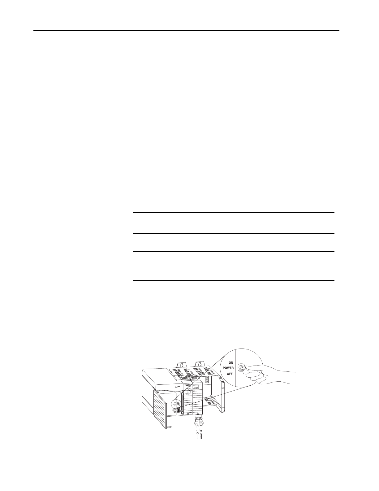
Chapter 3 Install the Redundancy System
Logix5563
Redundancy Module
Monitoring and Repair
Synchronization is preserved if the REDUNDANT channel has failed or is being
repaired. The repair of the REDUNDANT channel can be performed online
while the redundant chassis pair is running synchronized. To aid online repairs,
the fiber cable connections and SFP transceiver can be removed and inserted
under power.
It is not mandatory to have the REDUNDANT channel that is connected
between the two redundancy modules. The redundant chassis pair can be
synchronized with just one of the channels connected. The REDUNDANT
channel can be installed later while the chassis is running synchronized.
The status indicators on the front panel and the indicators and counters that are
displayed in the RMCT provide monitoring of the channel status.
Update Redundant Firmware
Use ControlFLASH or ControlFLASH Plus software to upgrade the firmware
of each module in each chassis.
IMPORTANT Apply power ONLY to the chassis that contains modules on which you are
upgrading firmware.
IMPORTANT Redundancy module firmware that is contained in the redundancy system
firmware bundle is designed for use with the 1756-RM, 1756-RM2,
1756-RMXT, and 1756-RM2XT redundancy modules.
Upgrade the Firmware in the First Chassis
Complete these steps to upgrade the firmware in the first chassis.
1. Apply power to the chassis.
58 Rockwell Automation Publication 1756-UM535I-EN-P - October 2020
Page 59

Install the Redundancy System Chapter 3
Logix 55xx
RUN
FORCE
SD
OK
Alphanumeric Display
OK indicator is red during selftest, and turns green if
firmware is already
downloaded.
Power Supply
indicator is green.
2. Set the mode switch on the controller to REM.
3. Wait for the redundancy module to complete its start-up scroll messages.
Check the module’s status indicators. Wait 45 seconds before you begin
updating the 1756-RM/1756-RM2 firmware. During this time, the
redundancy module conducts internal operations to prepare for an update.
Logix5563
Redundancy Module
Redundancy Module
CH2 CH1 OK
TIP If it is a new module, wait until APPLICATION UPDATE REQUIRED is
displayed. The status indicator flashes red.
4. Launch ControlFLASH or ControlFLASH Plus software and click Next
to begin the update process.
Rockwell Automation Publication 1756-UM535I-EN-P - October 2020 59
Page 60

Chapter 3 Install the Redundancy System
5. Select the catalog number of the module (upgrade the redundancy module
first) and click Next.
IMPORTANT The 1756-RM2 module uses different firmware than the 1756-RM and
1756-RMXT modules.
6. Expand the network driver to locate the redundancy module or module
you are upgrading.
7. Select the module and click OK.
8. Select the firmware revision that you want to update to and click Next.
9. Click Finish.
10. On the confirmation dialog box that appears click Yes.
IMPORTANT This process can take a few minutes. The system can look like it is not doing
anything, but it is. When the update is complete, the Update Status dialog
box appears and indicates that the update has successfully completed.
11. Click OK.
12. Verify that the redundancy module status displays PRIM, which indicates
a successful upgrade.
13. Complete steps 4
…12 for each module in the chassis.
IMPORTANT Power off the first chassis after you have verified a successful update of each
module.
60 Rockwell Automation Publication 1756-UM535I-EN-P - October 2020
Page 61

Install the Redundancy System Chapter 3
Upgrade the Firmware in the Second Chassis
Complete these steps to update the firmware for the modules in the second
chassis.
1. Apply power to the second chassis.
Designate the Primary and Secondary Chassis
2. Complete steps 3
beginning on page 58
3. Power off the second chassis after you have verified the successful upgrade
of each module.
Power on the chassis you want to designate as the primary chassis first. After you
have applied power, qualify the system so that all module pairs are at compatible
firmware revision levels.
IMPORTANT Do not apply power to the chassis until you have read the instructions for
Complete these steps to designate the primary and secondary chassis of a
redundant pair.
…12 in section Upgrade the Firmware in the First Chassis
for the modules in the second chassis.
designating the primary chassis. Applying power to the chassis in the
correct order is crucial to designating the primary and secondary chassis.
Do not attempt to designate a primary chassis before loading in an
application image.
Before you designate the primary chassis and qualify the system, make
sure that you have the latest firmware installed.
See Update Redundant Firmware on page 58
.
1. Verify that power is removed from both chassis.
2. Apply power to the chassis you want to designate as the primary chassis
and wait for the status indicators of the module to display PRIM.
3. Apply power to the chassis you want to designate as the secondary chassis.
4. Verify primary and secondary chassis designations by viewing the module
status display and the PRI indicator.
See Redundancy Module Status Indicators on page 209
redundancy module display information.
IMPORTANT If both modules have power applied to them simultaneously, the module
with the lowest IP address is designated as the primary chassis and displays
PRIM on the four-character display of the module. In addition, the PRI status
indicator on the primary redundancy module is green. The secondary chassis
displays either DISQ or SYNC, depending on the state of the secondary
chassis. In addition, the PRI status light on the secondary redundancy
module is not illuminated.
Rockwell Automation Publication 1756-UM535I-EN-P - October 2020 61
for specific
Page 62

Chapter 3 Install the Redundancy System
After Designation
When you first apply power to the designated primary and secondary chassis,
compatibility checks are carried-out between the redundant chassis. Then, if the
Auto-Synchronization parameter is set at Conditional, qualification begins.
TIP While the qualification occurs, the module status display transitions from DISQ
(disqualified) to QFNG (qualifying) to SYNC (synchronized). The qualification s
complete in 1…3 minutes and then module status display indicates the
qualification status.
Use this table as a reference when interpreting the qualification status of the
modules that are displayed on the module status display.
Module Status Display Interpretation
QFNG Qualification processes are in progress.
SYNC SYNC displays after qualification processes are complete.
This indicates that chassis configuration and the firmware revision levels are
compatible and that the secondary chassis is ready to assume control if there is a
major fault in the primary chassis.
DISQ…QFNG…DISQ If DISQ continues to display after about 3 minutes, one of these anomalies exists:
• Incorrect chassis configuration. That is, incompatible hardware is used.
• Incompatible firmware revisions are used between the primary and secondary
modules.
• Keeper parameters between ControlNet module partners are not the same.
• The partnered ControlNet modules are not set to the same node address.
• The partnered EtherNet/IP modules are not set to the same IP Configuration.
• The Auto-Synchronization parameter within the Redundancy Module
Configuration Tool is set to Never or Conditional (default setting).
Conversion from a Non-redundant to a Redundant System
To upgrade the standalone chassis to a redundant chassis pair:
1. Insert a redundancy module in a spare slot in the standalone chassis, and
2. Configure an identical chassis with compatible modules in the same slot as
the standalone chassis (including the redundancy module).
A partnered chassis that is designated as the secondary chassis stops functioning if
it contains:
• non-redundancy-compliant modules;
• or, modules not compatible with Enhanced redundancy;
• or, non-redundancy-compliant firmware
For more information, see Convert from a Non-redundant System on page 219
62 Rockwell Automation Publication 1756-UM535I-EN-P - October 2020
.
Page 63

Install the Redundancy System Chapter 3
Qualification Status Via the RMCT
To view the qualification attempt, access the Synchronization or Synchronization
Status tabs of the RMCT. These tabs provide information about qualification
attempts and redundant chassis compatibility.
For more information on how to use the RMCT, see Chapter 6
, Configure the
Redundancy Modules on page 89.
Figure 13 - RMCT Synchronization Status Tab
Figure 14 - Synchronization Status Tab for Chassis Compatibility
In addition, you can view events specific to qualification in the Event Log of the
RMCT.
Figure 15 - Event Log with Qualification Events
Reset the Redundancy Module
There are two ways to reset the module.
• Cycle power to the chassis.
• Remove the module from the chassis and reinsert the module.
IMPORTANT Do not choose to cycle power to the chassis if it causes you to lose control
of your process.
Rockwell Automation Publication 1756-UM535I-EN-P - October 2020 63
Page 64

Chapter 3 Install the Redundancy System
Remove or Replace the Redundancy Module
To remove or replace the redundancy module, follow these steps.
1. To disengage the upper and lower module tabs, push them.
2. Slide the module out of the chassis.
3. Insert the replacement in the same slot and move the fiber cable(s) to the
new module.
IMPORTANT If you want to resume system operation with an identical module, you
must install the new module in the same slot.
64 Rockwell Automation Publication 1756-UM535I-EN-P - October 2020
Page 65

Configure the EtherNet/IP Network
Top ic Pag e
Requested Packet Interval 65
IP Address Swapping 66
CIP Sync 69
Produce/Consume Connections 72
Configure EtherNet/IP Communication Modules in a Redundant System 75
Use a Redundancy System with Device Level Ring 76
Use a Redundancy System with Parallel Redundancy Protocol 77
Chapter 4
Requested Packet Interval
When using revisions earlier than 20.054, the RPI for I/O connections in a
redundancy-enabled controller tree must be less than or equal to 375 ms. When
using revision 20.054 or later, the RPI can be the same as a non-redundant
chassis.
CPU Usage
Ta b l e 4 describes CPU usage for EtherNet/IP™ communication modules.
Table 4 - System Resource Utilization Table
If the CPU utilization
rate is
0…80% No action is required.
Greater than 80% • Take steps to reduce your CPU utilization. See the EtherNet/IP Network
Then
Important: This range is the optimal rate.
Configuration User Manual, publication ENET-UM001.
• Adjust the requested packet interval (RPI) of your connection.
• Reduce the number of devices that are connected to your module.
Important: Your EtherNet/IP communication module can function at 100% CPU
capacity, but at or near this rate, you run the risk of CPU saturation and per formance
problems.
Rockwell Automation Publication 1756-UM535I-EN-P - October 2020 65
Page 66

Chapter 4 Configure the EtherNet/IP Network
IP Address Swapping
IP address swapping is a feature available to EtherNet/IP communication
modules in a redundancy system where a partnered set of EtherNet/IP
communication modules swap IP addresses during a switchover.
IMPORTANT You must use IP address swapping to use remote I/O and produce/consume
connections of an EtherNet/IP network.
Determine Use of IP Address Swapping
Depending on your EtherNet/IP network configuration, you can choose to use
IP address swapping between your partnered EtherNet/IP communication
modules in the event of a switchover.
If you want to Then
Minimize data server communication recovery time during switchover
Have your partnered EtherNet/IP communication modules on different subnets
Use Remote I/O or produce/consume.
Have your partnered EtherNet/IP communication modules on the same subnet
(1) For more information, see Data Server Communication Recovery Time Reduction During a Switchover on page 17.
(1)
Do not use IP address swapping
Use IP address swapping
If you are using different subnets, you are responsible for programming your
system to use the address and subnet of the new primary chassis in the event of a
switchover.
Do Not Use IP Address Swapping
If you do not use IP address swapping, assign unique values for these
configuration parameters at minimum on both EtherNet/IP communication
modules in the partnered set:
• IP address
IMPORTANT The IP address cannot be of the following format between the partner
EtherNet modules: aaa.bbb.ccc.ddd & aaa.bbb.ccc.(ddd+1)
Use IP Address Swapping
If you use IP address swapping, assign the same values for these configuration
parameters on both EtherNet/IP communication modules in the partnered set:
• IP address
•Subnet mask
• Gateway address
Figure 16
shows a partnered set of EtherNet/IP communication modules during
initial configuration.
66 Rockwell Automation Publication 1756-UM535I-EN-P - October 2020
Page 67

Configure the EtherNet/IP Network Chapter 4
Primary chassis Secondary Chassis
Assigned IP Address: 192.168.1.3
Primary Chassis Secondary Chassis
IP Address: 192.168.1.3 IP Address: 192.168.1.4
Figure 16 - IP Addresses of EtherNet/IP Communication Modules During System Configuration
CH2 CH1 OK
1756-L64
CH2 CH1 OK
1756-L64
When a redundancy system begins operating, the primary EtherNet/IP
communication module uses the IP address that is assigned during initial
configuration. The secondary EtherNet/IP communication module
automatically changes its IP address to the next highest value. When a switchover
occurs, the EtherNet/IP communication modules swap IP addresses.
For example, if you assign IP address 192.168.1.3 to both EtherNet/IP
communication modules in a partnered set, on initial system operation, the
secondary EtherNet/IP communication module automatically changes its IP
address to 192.168.1.4.
Figure 17
shows a partnered set of EtherNet/IP communication modules after
system operation begins.
Figure 17 - IP Addresses of EtherNet/IP Communication Modules After System Operation Begins
CH2 CH1 OK
1756-L64
Rockwell Automation Publication 1756-UM535I-EN-P - October 2020 67
CH2 CH1 OK
1756-L64
Page 68

Chapter 4 Configure the EtherNet/IP Network
TIP Do not assign IP addresses to EtherNet/IP communication modules outside
the partnered set to values that conflict with those values that are used in
the partnered set.
In the previous example, the partnered set uses 192.168.1.3 and
192.168.1.4. Use 192.168.1.5 or higher for all EtherNet/IP communication
modules outside the partnered set.
Figure 18 shows the partnered set of EtherNet/IP communication modules in
RSLinx® Classic software after system operation begins.
Figure 18 - IP Addresses in RSLinx Classic Software
Static Versus Dynamic IP Addresses
We recommend that you use static IP addresses on EtherNet/IP communication
modules in redundancy systems.
ATT EN TI ON : If you use dynamic IP addresses and a power outage, or other
network failure occurs, modules that use dynamic IP addresses can be
assigned new addresses when the failure is resolved. If the IP addresses
change, your application could experience a loss of control or other serious
complications with your system.
You cannot use dynamic IP addresses with IP address swapping.
Reset the IP Address for an EtherNet/IP Communication Module
If necessary, you can reset the IP address of a 1756-EN2x communication
module to the factory default value. To return to the factory default, set the
rotary switches on the module to 888 and cycle power.
After you cycle power to the EtherNet/IP communication module, you can
either set the switches on the module to the desired address, or set the switches to
999 and use one of these methods to set the IP address:
• BOOTP-DHCP server
• RSLinx Classic communication software
• Programming software
68 Rockwell Automation Publication 1756-UM535I-EN-P - October 2020
Page 69

Configure the EtherNet/IP Network Chapter 4
CIP Sync
With redundancy system revision 19.052 or greater, you can use CIP Sync™
technology. CIP Sync technology provides a mechanism to synchronize clocks
between controllers, I/O devices, and other automation products in your
architecture with minimal user intervention.
CIP Sync technology uses Precision Time Protocol (PTP) to establish a Master/
Slave relationship among the clocks for each CIP Sync-enabled component in
the system. One master clock, which is known as the Grandmaster, sets the clock
to which all other devices on the network synchronize their clocks.
IMPORTANT Before you use this enhancement in a redundancy system, revision 19.052 or
later, see these publications for a full understanding of CIP Sync technology
in any system:
• Integrated Architecture™ and CIP Sync Configuration Application
Technique, publication IA-AT003
• ControlLogix® System User Manual, publication 1756-UM001
Consider these points when you use CIP Sync technology in a redundancy
system, revision 19.052 or later:
• If you enable CIP Sync Time Synchronization in the controllers in a
redundant chassis pair, you must also enable Time Synchronization in the
EtherNet/IP communication modules in the redundant chassis pair so all
devices have one path to the Grandmaster. To enable Time
Synchronization in the EtherNet/IP communication modules, change the
Time Sync Connection from None (default) to Time Sync and Motion.
If time synchronization is enabled in any controller in the primary chassis
of a disqualified redundant chassis pair, and no other devices in the
primary chassis have time synchronization enabled, the redundant chassis
pair attempts to qualify. However, in these application conditions, the
attempt to qualify fails.
• While CIP Sync technology can handle multiple paths between master
and slave clocks, it resolves mastership most effectively if you configure the
redundant paths so that Time Synchronization is enabled in only the
minimum required number of EtherNet/IP communication modules.
For example, if your redundant chassis pair has three 1756-EN2T
communication modules and all are connected to the same network,
enable Time Synchronization in only one of the modules.
Rockwell Automation Publication 1756-UM535I-EN-P - October 2020 69
Page 70

Chapter 4 Configure the EtherNet/IP Network
• If the primary controller is the Grandmaster, the redundancy system
automatically manages the CIP Sync clock attributes so that the controller
in the primary chassis is always set to be the Grandmaster instead of the
secondary controller. This clock management makes sure of a change to a
new Grandmaster when the redundancy system switches over.
• When a switchover occurs, these events take place:
– The Grandmaster status transfers from the original primary controller
to the new primary controller. This transfer can take longer to
complete than if Grandmaster status was transferred between devices
in a non-redundant system.
– After the switchover is complete, system synchronization can take
longer in a redundancy system, revision 19.052 or later, which uses
CIP™ technology than one that does not.
• If you attempt to use the Redundant System Update (RSU) feature to
update a redundancy system, revision 16.081 or earlier, which uses
Coordinated System Time (CST), the redundancy system, revision
19.052 or later, does not permit a locked switchover and the update fails to
complete.
To work around this restriction, first disable CST Mastership in the
original redundancy system and then use RSU to update the redundancy
system to revision 19.052 or later.
Figure 19 on page 71
shows an example redundancy system, revision 19.052 or
later, that uses CIP Sync technology.
70 Rockwell Automation Publication 1756-UM535I-EN-P - October 2020
Page 71

Configure the EtherNet/IP Network Chapter 4
M
S
S
S
S
S
M
P1
P1
S
S
S
S
S
M
S
M
S SS
M
S SS
P2
S
SS
M
G
Primary Chassis
CIP Sync
Stratix® 5700
Supervisory
CIP Sync
EtherNet
CIP Sync
CIP Sync
CIP Sync
CIP Sync
CIP Sync
CIP Sync
CIP Sync
CIP Sync
Fiber Optic Cable
G = Grandmaster (time source)
M = Master
S = Slave
P1 and P2 = Priorities
Secondary Chassis
Stratix 5700
EtherNet
CIP Sync
CIP Sync
CIP Sync
CIP Sync
CIP Sync
Figure 19 - Redundancy System, Revision 19.052 or greater, Using CIP Sync Technology
Rockwell Automation Publication 1756-UM535I-EN-P - October 2020 71
Page 72

Chapter 4 Configure the EtherNet/IP Network
CH2 CH1 OK CH2 CH1 OK
1756-L64
1756-L64
1756-L64
Primary Chassis Secondary Chassis
Controller 1
Produced Tag
Controller 2
Consu med Tag
Produce/Consume Connections
With redundancy system revision 19.052 or later, you can use produce/consume
connections over an EtherNet/IP network. Controllers let you produce
(broadcast) and consume (receive) system-shared tags.
IMPORTANT Sockets are supported in the 1756-EN2T, 1756-EN2TR and 1756-EN2F
modules, firmware revision 5.008 or later. For additional information, see
the EtherNet/IP Socket Interface Application Technique,
publication ENET-AT002
.
IMPORTANT Unicast functionality in redundancy systems supports produced tags.
Unicast consumed tags are not supported.
TIP When using ControlLogix 5570 controllers in your system, you must use
revision 19.053 or greater.
Figure 20 - Example System Using Produced and Consumed Tags
These requirements exist when you use produced and consumed connections
over an EtherNet/IP network in a redundancy system, revision 19.052 or
greater:
• You cannot bridge produced and consumed tags over two networks. For
two controllers to share produced or consumed tags, both must be
attached to the same network.
• Produced and consumed tags use connections in both the controllers and
the communication modules being used.
72 Rockwell Automation Publication 1756-UM535I-EN-P - October 2020
Page 73

Configure the EtherNet/IP Network Chapter 4
• Because the use of produced and consumed tags uses connections, the
number of connections available for other tasks, such as the exchange of
I/O data, is reduced.
The number of connections available in a system depends on controller
type and network communication modules used. Closely track the
number of produced and consumed connections to leave as many as
necessary for other system tasks.
• Produced and consumed tags must be configured in both the producing
controller and the consuming controller. Produced tags in a redundant
ControlLogix controller can be configured as either multicast or unicast.
Consumed tags by a redundant ControlLogix controller must be
configured as multicast in the producing controller.
• When you add an Ethernet module for the redundancy chassis to the I/O
tree of a remote consuming controller, change the Connection setting
from Rack Optimized to None. If this setting is not changed the
configured connection can briefly drop during a switchover.
Rockwell Automation Publication 1756-UM535I-EN-P - October 2020 73
Page 74

Chapter 4 Configure the EtherNet/IP Network
Produced/Consumed Tags between Primary Controllers and Nonredundant Controllers
The connection from the remote controller to the redundant controller can
briefly drop during a switchover. This condition can occur if the EtherNet/IP
communication modules of the remote chassis do not use specific firmware
revisions. The controllers in the redundant chassis pair must also produce tags
over the EtherNet/IP network that the controllers in the remote chassis consume.
Use these firmware revisions for EtherNet/IP communication modules in the
remote chassis to maintain connections during a switchover.
Table 5 - Minimum Firmware Revision for Communication Modules in Remote Chassis
Communication Module in Remote Chassis Minimum Firmware Revision
1756-EN2F 5.008 (unsigned)
5.028 (signed)
1756-EN2T
1756-EN2TR
1756-EN3TR
1756-EN4TR
1756-ENBT 6.001
1768-ENBT 4.001
1769-L2x
1769-L3xE
1788-ENBT 3.001
CompactLogix 5380 controllers
ControlLogix 5580 controllers
CompactLogix 5480 controllers 32.012
4.002
19.011
28.011
IMPORTANT The minimum firmware revisions that are listed in Tab le 5 apply only to
EtherNet/IP communication modules in the remote chassis.
In a redundant chassis pair, you can use only the ControlLogix modules that are
listed in the respective bundle's release notes
74 Rockwell Automation Publication 1756-UM535I-EN-P - October 2020
Page 75

Configure the EtherNet/IP Network Chapter 4
Configure EtherNet/IP Communication Modules in a Redundant System
Use these procedures to configure EtherNet/IP communication modules that
are used in redundant chassis.
Before You Begin
Before you begin configuring the EtherNet/IP communication modules in the
redundant chassis, verify that these tasks have been completed:
• The redundancy modules are installed and connected in the redundant
chassis.
• A plan for IP address use has been executed:
– If you are using IP address swapping, plan for the use of two
consecutive IP addresses in the partnered set.
– If you are not using IP address swapping, plan for the use of two IP
addresses.
• Know the subnet mask and gateway address for the Ethernet network the
redundant modules are to operate on.
Options for Setting the IP Addresses of EtherNet/IP Communication Modules
By default, ControlLogix EtherNet/IP communication modules ship with the IP
address set to 999 and with Bootstrap Protocol (BOOTP)/Dynamic Host
Configuration Protocol (DHCP)-enabled.
Use one of these tools to set the IP addresses for your EtherNet/IP
communication modules:
• Rotary switches on the module
• RSLinx Classic communication software
• Programming software
• BOOTP/DHCP utility
Half/Full Duplex Settings
The redundancy system uses the duplex settings of the EtherNet/IP
communication module that is the primary. After a switchover, the duplex
settings of the new primary EtherNet/IP communication module are used. By
default, the duplex setting is automatic. We recommend that you use this setting
whenever possible.
To avoid communication errors, configure both the primary and secondary
EtherNet/IP communication modules with the same duplex settings. If you use
different duplex settings on partnered EtherNet/IP communication modules,
then messaging errors can occur after a switchover.
Rockwell Automation Publication 1756-UM535I-EN-P - October 2020 75
Page 76

Chapter 4 Configure the EtherNet/IP Network
Use a Redundancy System with Device Level Ring
Device Level Ring (DLR) is an EtherNet/IP protocol defined by ODVA, Inc.
DLR provides a means for detecting, managing, and recovering from single faults
in a ring-based network.
A DLR network includes the following types of ring nodes.
Node Description
Ring supervisor A ring supervisor provides these functions:
Ring participants Ring participants provide these functions:
Redundant gateways
(option al)
• Manages traffic on the DLR network
• Collects diagnostic information for the net work
A DLR network requires at least one node to be configured as ring supervisor.
IMPORTANT: By default, the supervisor function is disabled on supervisor-capable
devices, so they are ready to participate on a linear or star network or as a ring node on a
DLR network.
In a DLR network, you must configure at least one of the supervisor-capable devices as
the ring supervisor before physically connecting the ring. If you do not, the DLR network
does not work.
We recommend to assign at least one supervisor outside of the redundant c hassis pair to
prevent losing supervision of the DLR during switchover.
For more information on DLR operation see the EtherNet/IP Device Level Ring
Application Technique, publication ENET-AT007
• Process data that is transmitted over the network.
• Pass on the data to the next node on the network.
• Report fault locations to the ac tive ring supervisor.
When a fault occurs on the DLR network, ring participants reconfigure themselves and
relearn the network topology.
Redundant gateways are multiple switches connected to a single DLR network and also
connected together through the rest of the network.
Redundant gateways provide DLR network resiliency to the rest of the network.
.
Depending on their firmware capabilities, both devices and switches can operate
as supervisors or ring nodes on a DLR network. Only switches can operate as
redundant gateways.
For more information about DLR, see the EtherNet/IP Device Level Ring
Application Technique, publication ENET-AT007
.
76 Rockwell Automation Publication 1756-UM535I-EN-P - October 2020
Page 77

Configure the EtherNet/IP Network Chapter 4
Use a Redundancy System with Parallel Redundancy Protocol
Parallel Redundancy Protocol (PRP) is defined in international standard
IEC 62439-3 and provides high-availability in Ethernet networks. PRP
technology creates seamless redundancy by sending duplicate frames to two
independent network infrastructures, which are known as LAN A and LAN B.
A PRP network includes the following components.
Component Description
LAN A and LAN B Redundant, active Ethernet networks that operate in parallel.
Double attached node (DAN) An end device with PRP technology that connects to both LAN A and LAN B.
Single attached node (SAN) An end device without PRP technology that connects to either LAN A or LAN B.
A SAN does not have PRP redundancy.
Redundancy box (RedBox) A switch with PRP technology that connects devices without PRP technology to
Virtual double attached node
(VDAN)
Infrastructure switch A switch that connects to either LAN A or LAN B and is not configured as a RedBox.
both LAN A and LAN B.
An end device without PRP technology that connects to both LAN A and LAN B
through a RedBox.
A VDAN has PRP redundancy and appears to other nodes in the network as a DAN.
For more information about PRP topologies and configuration guidelines, see
the EtherNet/IP Parallel Redundancy Protocol Application Technique,
publication ENET-AT006
.
Rockwell Automation Publication 1756-UM535I-EN-P - October 2020 77
Page 78

Chapter 4 Configure the EtherNet/IP Network
Notes:
78 Rockwell Automation Publication 1756-UM535I-EN-P - October 2020
Page 79

Configure the ControlNet Network
CH2 CH1 OK
CH2 CH1 OK
Primary chassis Secondary Chassis
Control ler 1
Produced Tag
Control ler 2
Consu med Tag
Top ic Pag e
Produce/Consume Connections 79
Network Update Time 81
Scheduled or Unscheduled Network 83
Schedule a New Network 84
Update an Existing Scheduled Network 87
Check the Network Keeper States 88
Chapter 5
Produce/Consume Connections
You can use produce/consume connections over a ControlNet® network.
Controllers let you produce (broadcast) and consume (receive) system-shared
tags.
Figure 21 - Example System Using Produced and Consumed Tags
Rockwell Automation Publication 1756-UM535I-EN-P - October 2020 79
Page 80

Chapter 5 Configure the ControlNet Network
Keep these points in mind when you use produced and consumed connections
over a ControlNet network in a redundancy system:
• During a switchover, the connection for tags that are consumed from a
redundant controller can drop briefly.
– The data does not update.
– The logic acts on the last data that it received.
After the switchover, the connection is re-established and the data begins
to update again.
• You cannot bridge produced and consumed tags over two networks. For
two controllers to share produced or consumed tags, both must be
attached to the same network.
• Produced and consumed tags use connections in both the controllers and
the communication modules being used.
• Because the use of produced and consumed tags uses connections, the
number of connections available for other tasks, such as the exchange of
I/O data, is reduced.
The number of connections available in a system depends on controller
type and network communication modules used. Closely track the
number of produced and consumed connections to leave as many as
necessary for other system tasks.
80 Rockwell Automation Publication 1756-UM535I-EN-P - October 2020
Page 81

Configure the ControlNet Network Chapter 5
ControlNet Network 1
NUT = 5 ms
ControlNet Network 2
NUT =
21 ms
Redundant Chassis Pair
Network Update Time
The network update time (NUT) that you specify for your redundant system
affects your system performance and your switchover response time. Typical
NUTs used with redundant systems range from 5…10 ms.
NUTs with Multiple ControlNet Networks
You can choose to use multiple ControlNet networks with your redundancy
system.
Figure 22 - Example of Two ControlNet Networks
CH2 CH1 OK
1756-L63
CH2 CH1 OK
1756-L63
When you use multiple ControlNet networks, the networks must use compatible
NUTs. Compatible NUTs are determined based on the network that uses the
smallest NUT.
Rockwell Automation Publication 1756-UM535I-EN-P - October 2020 81
Page 82

Chapter 5 Configure the ControlNet Network
Use Ta b l e 6 to determine the compatible NUTs for your system.
Table 6 - C ompatible NUT Values for Multiple ControlNet Networks
If the smallest NUT of a
network is (ms)
215
317
419
521
623
725
827
929
10 31
11 33
12 35
13 37
14 39
15 41
16 43
17 46
18 48
19 50
20 52
21 55
22 57
23 59
24 62
25 64
26 66
27 68
28 71
29 73
30 75
31 78
32 80
33 82
34 84
35 87
36 89
37…90 90
Then the largest NUT of any other network must be less
than or equal to (ms)
82 Rockwell Automation Publication 1756-UM535I-EN-P - October 2020
Page 83

Configure the ControlNet Network Chapter 5
Scheduled or Unscheduled Network
It is up to you to if you want to use a scheduled or unscheduled network.
Use a Scheduled Network
Schedule or reschedule your ControlNet network when you execute these tasks:
• Commission a new redundant system.
• Add a chassis of remote ControlLogix® I/O that is set to use the
Rack Optimized communication format.
• Add any remote I/O besides ControlLogix I/O. For example, if you add
FLEX™ I/O modules, you must schedule the network.
• Use produced/consumed data. If you add a produced/consumed data tag,
you must reschedule the ControlNet network.
To schedule or reschedule your ControlNet network, you put your redundant
system in Program mode.
Use an Unscheduled Network
You can use an unscheduled network when you:
• Add a remote I/O chassis of ControlLogix I/O that does not use the
Rack Optimized communication format. That is, direct connections to
the I/O are used.
• Add a ControlLogix I/O module to a chassis that has already been
scheduled and uses the Rack Optimized communication format.
• Add some drives that support adding I/O while online.
• Use ControlNet to monitor HMI or the controller program execution
online.
You can add those components to the unscheduled network while your
redundant system is online and in Run mode. We recommend that you do not
use an unscheduled network for all of your I/O connections.
The use of 1756-CN2, 1756-CN2R, and 1756-CN2RXT modules provide
increased capacity for adding I/O while online compared to 1756-CNB or
1756-CNBR modules. With this increased capacity, you can easily add I/O and
increase ControlNet connections that are used without affecting your redundant
system performance.
Rockwell Automation Publication 1756-UM535I-EN-P - October 2020 83
Page 84

Chapter 5 Configure the ControlNet Network
Add Remote ControlNet Modules While Online
If you are adding a remote I/O chassis that is composed of a ControlLogix
ControlNet module and ControlLogix I/O while your redundant system is
running (online), make these considerations:
• Do not use Rack Optimized communication formats. The ControlNet
module and I/O must be configured for direct connections.
• For each remote I/O module used, plan for one direct connection to be
used.
Schedule a New Network
Complete these steps to schedule a new ControlNet network for a redundancy
system.
IMPORTANT Before you schedule a ControlNet network, turn on the power to both
redundant chassis.
If you schedule a ControlNet network while the secondary chassis is off,
the keeper signature of a 1756-CN2 or 1756-CN2R module can mismatch
its partner. This action can cause the secondary chassis to fail to
synchronize.
1. Turn on the power to each chassis.
2. Start RSNetWorx™ for ControlNet software.
3. From the File menu, choose New.
4. At the New File dialog box, choose a configuration type.
This example uses ControlNet Configuration.
5. From the Network menu, choose Online.
6. Select your ControlNet network and click OK.
84 Rockwell Automation Publication 1756-UM535I-EN-P - October 2020
Page 85

Configure the ControlNet Network Chapter 5
7. From the Network menu, choose Enable Edits.
8. From the Network menu, choose Properties.
9. In the Network Parameters tab, enter the parameters that are appropriate
for your system.
Parame ter Spec ify
Network Update Time (ms) The minimum repetitive interval when data is sent over the ControlNet
Max Scheduled Address The highest node number that uses scheduled communication on the
Max Unscheduled Address The highest node number that you use on the network.
Media Redundancy The ControlNet channels that you are using.
Network Name A name for identifying the ControlNet network.
Rockwell Automation Publication 1756-UM535I-EN-P - October 2020 85
network.
network.
Page 86

Chapter 5 Configure the ControlNet Network
10. On the Media Configuration tab, add repeaters, fiber, and coax to
accurately represent your the worse case path between any two ControlNet
nodes.
If the media configuration does not accurately represent the maximum
propagation delay between any two nodes, your network may experience
errors.
11. Click Apply.
12. Click OK.
13. From the Network menu, choose Single Pass Browse.
14. From the File menu, choose Save.
15. Type a name for the file that stores the network configuration, then
click Save.
16. Click Optimize and rewrite Schedule for all Connections (default) and
click OK.
You have finished scheduling your new ControlNet network.
86 Rockwell Automation Publication 1756-UM535I-EN-P - October 2020
Page 87

Configure the ControlNet Network Chapter 5
Update an Existing Scheduled Network
If you are adding the redundant chassis to an existing ControlLogix system that
uses a ControlNet network, complete these steps to update the existing
ControlNet network.
1. Turn on the power to each chassis.
2. Start RSNetWorx for ControlNet software.
3. From the File menu, choose Open.
4. Select the file for the network and click Open.
5. From the Network menu, choose Online.
6. From the Network menu, choose Enable Edits.
7. From the Network menu, choose Properties.
8. In the Network Parameters tab, update the parameters specific to your
system.
9. Click OK.
10. From the Network menu, choose Single Pass Browse.
11. From the File menu, choose Save.
Rockwell Automation Publication 1756-UM535I-EN-P - October 2020 87
Page 88

Chapter 5 Configure the ControlNet Network
12. Click Optimize and rewrite schedule for all connections and click OK.
13. Click OK.
You have completed updating your scheduled ControlNet network.
Check the Network Keeper States
After you schedule your ControlNet network, check the states of keeper-capable
nodes. Checking the status of keeper-capable nodes is important because if a
major network disruption occurs, the keepers provide network configuration
parameters that are required to recover.
For more information about keepers and their function in a ControlNet
network, see the ControlNet Network Configuration User Manual,
publication CNET-UM001
To check the status of keepers on the ControlNet network, complete these steps.
1. In RSNetWorx for ControlNet software, from the Network menu choose
Keeper Status.
.
2. Verify that one keeper-capable device outside the redundant chassis is
indicated as active and valid.
88 Rockwell Automation Publication 1756-UM535I-EN-P - October 2020
Page 89

Configure the ControlNet Network Chapter 5
Active and valid keeper
device.
Keeper-capable devices are valid.
Keeper signatures are the same.
3. Verify that all keeper-capable devices on the network are valid.
4. Verify that all nodes on the network have the same keeper signature.
TIP If the keeper signatures of partnered ControlNet modules are different,
your redundant chassis can fail to synchronize.
If the keeper signatures of your partnered ControlNet modules are
different, update the keepers of the redundant ControlNet modules.
Rockwell Automation Publication 1756-UM535I-EN-P - October 2020 89
Page 90

Chapter 5 Configure the ControlNet Network
Save the Project for Each Primary Controller
After you have scheduled your ControlNet networks, go online with each
controller in your primary chassis, and upload and save the project. This process
makes downloading a project easier in the future because you won’t be required
to reschedule the network after completing the download.
Automatic Keeper Crossloads
The 1756-CN2, 1756-CN2R, and 1756-CN2RXT ControlNet modules have
an Automatic Keeper Crossload feature that makes replacing a ControlNet
module in a redundant chassis easier. The Automatic Keeper Crossload feature
also reduces the need to use RSNetWorx for ControlNet software once the
system is running.
With the Automatic Keeper Crossload feature, ControlNet modules can
automatically upload the keeper signature and network parameters from the
active keeper of a ControlNet network.
To replace a ControlNet module that has been configured and scheduled on the
ControlNet network, remove the existing module and insert a
1756-CN2, 1756-CN2R, or 1756-CN2RXT module. The module that you are
inserting must be unconfigured or have a keeper signature of all zeros.
TIP To clear the keeper signature of a 1756-CN2, 1756-CN2R, or
1756-CN2RXT module, complete these steps.
1. Disconnect the module from the ControlNet network and remove it
from the chassis.
2. Set the node address switches to 00.
3. Insert the module back into the chassis and wait for the status
display to indicate Reset Complete.
4. Remove the module and set the node address switches to the
intended node address.
5. Insert the module into the chassis.
After being inserted and connected to the ControlNet network, the
unconfigured 1756-CN2, 1756-CN2R, and 1756-CN2RXT modules crossload
the appropriate configuration from the active keeper on the ControlNet
network. The modules then become configured with the appropriate keeper
signature.
90 Rockwell Automation Publication 1756-UM535I-EN-P - October 2020
Page 91

Configure the Redundancy Modules
Top ic Pag e
About the Redundancy Module Configuration Tool (RMCT) 91
Determine If Further Configuration Is Required 92
Use the RMCT 93
Module Info Tab 96
Configuration Tab 98
Synchronization Tab 101
Synchronization Status Tab 104
System Update Tab 105
Chapter 6
About the Redundancy Module Configuration Tool (RMCT)
The Redundancy Module Configuration Tool (RMCT) is used to configure the
redundancy modules and to determine the status of the redundancy system.
Use the RMCT to complete these configuration-related tasks:
• Set Auto-Synchronization parameters.
• Set the time and date of redundancy modules.
• View and set module information.
• View and set Chassis ID parameters (Chassis A, Chassis B).
• Lock the redundant system for an update.
• Conduct a test switchover.
You can also use this functionality available with the RMCT to determine the
status of the redundant system:
• View error diagnostics specific to redundant chassis.
• View qualification and compatibility status of partnered modules.
• Identify noncompliant modules for removal.
• View redundant system event history.
Rockwell Automation Publication 1756-UM535I-EN-P - October 2020 91
Page 92

Chapter 6 Configure the Redundancy Modules
Determine If Further Configuration Is Required
The default configuration of the redundancy modules lets you synchronize your
redundant chassis without additional configuration if you are using a basic
redundant chassis pair.
However, some applications and uses of the redundancy system can require
additional configuration. For example, you must use the RMCT for additional
configuration if you must complete any of these tasks:
• Set the redundancy modules to a different time or date (recommended).
TIP If you set the time and date of a redundancy module per the workstation time
and date, it can be helpful in analyzing redundancy logs in the future.
• Program your controller to control the redundant system.
• Change the redundancy synchronization options of the redundant system.
• Change the synchronization states of your redundant chassis.
• Conduct a test switchover.
• Complete a firmware update of a module in the redundant chassis while
the system is online.
If you must complete any of these tasks, see the sections that follow.
92 Rockwell Automation Publication 1756-UM535I-EN-P - October 2020
Page 93

Configure the Redundancy Modules Chapter 6
Use the RMCT
To access and begin using the RMCT, launch RSLinx® Classic software and
browse to your redundancy module. Right-click the redundancy module and
choose Module Configuration.
TIP If you cannot see the Module Configuration option in the list, then the
compatible version of the RMCT is not installed.
When you access the RMCT, the dialog box always indicates the status of the
redundancy chassis in the bottom-left corner.
Rockwell Automation Publication 1756-UM535I-EN-P - October 2020 93
Page 94

Chapter 6 Configure the Redundancy Modules
Identify the RMCT Version
You must use a version of the RMCT that is compatible with your redundancy
module firmware.
Beginning with version 20.054, the redundancy module firmware reports back to
the Redundancy Module Configuration Tool (RMCT) as to which version of
the RMCT is compatible. If there is an incompatibility, the RMCT shows only
the Module Info tab and indicates the version that the firmware is compatible
with.
For more information on the RMCT compatibility, see Knowledgebase Article
Redundancy Module Configuration Tool (RMCT)
To find the latest firmware bundle on the website, follow these steps.
1. The Redundancy Module Configuration Tool (RMCT) can be
downloaded from the Product Compatibility and Download Center
under the Firmware Downloads.
.
2. Search by the redundancy bundle used with your system to locate the
proper RMCT. The bundle is named by the firmware that is on the
processor in the redundancy system.
3. Depending on the version of the bundle, the RMCT may be included with
the firmware bundle or separate:
94 Rockwell Automation Publication 1756-UM535I-EN-P - October 2020
Page 95

Configure the Redundancy Modules Chapter 6
Complete these steps to check or verify the version of the Redundancy Module
Configuration Tool (RMCT) that you have installed.
TIP The RMCT launches at the version that is compatible with the 1756
redundancy module firmware that is installed.
If you have not updated your 1756 redundancy module firmware after
upgrading your RMCT version, the RMCT version that is indicated can
differ from version you updated to. You can also check the RMCT version
that you have installed by using Add or Remove Programs in the Control
Panel.
1. Launch RSLinx Classic software.
2. Click the RSWho icon.
3. Right-click your redundancy module and choose Module Configuration.
The Module Configuration dialog box opens.
4. Right-click the title bar and choose About.
The About dialog box opens and indicates the RMCT version.
Rockwell Automation Publication 1756-UM535I-EN-P - October 2020 95
Page 96

Chapter 6 Configure the Redundancy Modules
This should show the version you need based on your bundle or higher.
The RMCT always shows the latest version installed, and later versions are
backwards compatible with earlier versions.
Update the RMCT Version
The RMCT version that is compatible with your redundancy module firmware is
included in the downloads for most redundancy bundles.
• For redundancy bundles that use firmware revision 20.009 or later for
1756-RM2 modules, the RMCT is included in the redundancy bundle
and is not available for separate download.
• For redundancy bundles that use firmware revision earlier than 20.009,
you can download the RMCT separately as a product add-on.
To launch the installation of the RMCT, open the folder that contains the
redundancy firmware revision and double-click the executable file titled
Redundancy_Module_CT.exe.
The RMCT Installation Wizard opens and prompts you with the steps to install
the RMCT.
Module Info Tab
The Module Info tab of the RMCT provides a general overview of the
identification and status information of the redundancy module. This status
information is updated approximately once every two seconds.
TIP Not all indicators are shown for 1756-RM/A and 1756-RM/B modules.
96 Rockwell Automation Publication 1756-UM535I-EN-P - October 2020
Page 97

Configure the Redundancy Modules Chapter 6
These parameters are indicated in the Module Info tab.
Table 7 - Module Info Tab - Parameters Indicated
Parameter Description
Vendor Name of the vendor of the redundancy module.
Product Type General product type of the redundancy module.
Product Code CIP™ product code for the redundancy module.
Revision Major and minor revision information for the redundancy module.
Redundancy Module Serial
Number
Product Name Predefined catalog name of the redundancy module.
General Status General state of the redundancy module. Possible values include Startup, Load,
Major Fault The major fault status of a redundancy module. When a major fault is detected,
Minor Fault The minor fault status of a redundancy module. When a minor fault is detected,
Error Cod e Error code that is related to the fault if one exists.
Error Message Text-based message that describes the error if a fault exists.
Recovery Message Text-based message that indicates the recovery from a fault.
Total Indicates the number of channel switchovers that have occurred from CH1 to CH2
Periodic Indicates the number of switchovers that have occurred between CH1 and CH2
Max Periodic Switchovers The maximum number that is recorded in the Periodic counter. The time of the
CH1 Status Fiber Channel 1 status.
CH2 Status Fiber Channel 2 status. See CH1 Status on page 97
Chassis Platform Configuration Indicates configuration (version 19.05x and later always displays ‘enhanced’).
(1) The Periodic counters can be used to identify a burst of switchovers that can take place due to intermittent channel failures
within a few seconds. The recorded time can be helpful to correlate the switchover occurrences with any external failures that
have occurred on the fiber cables.
Serial number of the redundancy module.
Faul t, and OK.
the system does not provide redundancy support.
the system continues to provide redundancy support.
and vice versa on the module since its last powerup. It is reset to 0 automatically
by firmware on a power cycle.
over the last 10-second interval. The counter is constantly updated to reflect the
value that is recorded at every 10-second interval. The counter is automatically
reset to 0 on a power cycle.
update is recorded every time that the counter is updated. The counter is
automatically reset to 0 on a power cycle and can also be reset by clicking the
Reset button.
The status shows the operating condition of the respec tive fiber channels in terms
of one of the following values:
(1)
– Unknown - Operating state is not yet determined
– Active - Channel is operating normally as the ACTIVE channel
– Redundant - Channel is operating normally as the REDUNDANT channel
– Link Down - Channel is disconnected. Causes can be: the cable is
disconnected/broken/damaged; signal is attenuated, connector is loose,
the partner 1756-RM2 module is power down or in a major fault state
– No SFP - No transceiver was detected, it has failed, it is loosely connected, it
is not installed
– SFP !Cpt - Transceiver is not a Rockwell Automation supported unit
– SFP Fail - Transceiver is in a failed state
.
In addition, you can click Change to edit the User-Defined Identity parameters
to meet your application needs.
Rockwell Automation Publication 1756-UM535I-EN-P - October 2020 97
Page 98

Chapter 6 Configure the Redundancy Modules
Configuration Tab
Use the Configuration tab to set redundancy options and the internal clock of
the redundancy module. After you modify a parameter, the Apply Workstation
Time button becomes active.
98 Rockwell Automation Publication 1756-UM535I-EN-P - October 2020
Page 99

Configure the Redundancy Modules Chapter 6
Auto-synchronization
The first parameter in the Configuration tab is the Auto-Synchronization
parameter. The value that you chose for this parameter determines a significant
part of your redundant system behavior.
TIP Verify that your Auto-Synchronization parameter is at the proper value
before you modify your redundant system. This verification helps
prevent system errors.
For example, if you are upgrading your redundant system firmware,
verify that this parameter is set to Never or Conditional before
disqualifying your secondary chassis. If this parameter is Always, you
cannot properly disqualify your chassis and conduct the update.
Use the following table to determine the Auto-Synchronization setting that best
suits your application.
If you use this parameter This synchronization behavior results
Never The system remains in the same state, that is, either synchronized or
Always The system automatically synchronizes regularly.
Conditional The system behavior with this setting is dependent on the Auto-
disqualified, until one of these events takes place:
• A command is issued from the RMCT to either synchronize or disqualify.
• The controller commands synchronization or disqualification by using a
MSG instruction. For this action to occur, Enable User Program Control must
be checked.
• A fault on the primary causes a switchover.
If you attempt to disqualify the system by using the Disqualify Secondary
command in the RMCT, the resulting disqualification is temporary as the
system automatically qualifies and synchronizes again.
If the controller program disqualifies the system, the resulting disqualification
is also temporary.
Synchronization state of your system, found in the lower left portion of the
RMCT window after setting t he Auto-Synchronization parameter to
Conditional:
• If your Auto -Synchronization parameter is set to Conditional and your
Auto-Synchronization state is 'Conditional, Enabled', then the system
continually atte mpts to synchronize.
• If your Auto -Synchronization parameter is set to Conditional and your
Auto-Synchronization state is 'Conditional, Disabled', then the system does
not automatically attempt to synchronize.
To change from 'Conditional, Enabled' to 'Conditional, Disabled', click
Disqualify Secondary on the Synchronization tab.
To change from 'Conditional, Disabled' to 'Conditional, Enabled', click
Synchronize Secondary on the Synchronization tab.
Rockwell Automation Publication 1756-UM535I-EN-P - October 2020 99
Page 100

Chapter 6 Configure the Redundancy Modules
Chassis ID
The chassis ID parameter is used to assign a generic label to the chassis that house
the redundancy modules. The available chassis labels are Chassis A and Chassis B.
If you change the chassis label in the RMCT of the primary redundancy module,
the secondary module and chassis are automatically assigned the other chassis
label.
The chassis label that is assigned to the module remains associated with the same
physical chassis, regardless of its primary or secondary control designation.
Enable User Program Control
Check Enable User Program Control in the Configuration tab if you plan to use
MSG instructions in your controller program to initiate a switchover, change the
redundancy module time, or synchronize.
If you leave Enable User Program Control unchecked, the redundancy modules
do not accept any commands from the controller.
Redundancy Module Date and Time
The Redundancy Module Date and Time parameters can be applied separate
from the Redundancy Module Options parameters. The time that is specified
with these parameters is the time that the event logs reference when a redundant
system event occurs.
To change the redundancy module time settings, use the pull-down menu or type
your changes then click Set to implement time changes. Or, to set the time of the
redundancy module to match that of the workstation, click Apply Workstation
Time.
IMPORTANT We recommend that you set the redundancy module date and time when
you commission a system. We also recommend that you periodically check
the date and time settings to make sure that they match the settings of the
controller.
If a power failure occurs on the redundant chassis, you must reset the date
and time information of the redundancy modules. The modules do not
retain those parameters when power is lost.
100 Rockwell Automation Publication 1756-UM535I-EN-P - October 2020
 Loading...