

Rockwell Automation ControlLogix, GuardLogix, CompactLogix, Compact GuardLogix, SoftLogix Reference Manual

Logix 5000 Controllers
Design Considerations
ControlLogix, GuardLogix, CompactLogix,
Compact GuardLogix, SoftLogix
Reference Manual
Original Instructions
Logix 5000 Controllers
Important User Information
Read this document and the documents listed in the additional resources section about installation, configuration, and
operation of this equipment before you install, configure, operate, or maintain this product. Users are required to familiarize
themselves with installation and wiring instructions in addition to requirements of all applicable codes, laws, and standards.
Activities including installation, adjustments, putting into service, use, assembly, disassembly, and maintenance are required to
be carried out by suitably trained personnel in accordance with applicable code of practice.
If this equipment is used in a manner not specified by the manufacturer, the protection provided by the equipment may be
impaired.
In no event will Rockwell Automation, Inc. be responsible or liable for indirect or consequential damages resulting from the use
or application of this equipment.
The examples and diagrams in this manual are included solely for illustrative purposes. Because of the many variables and
requirements associated with any particular installation, Rockwell Automation, Inc. cannot assume responsibility or liability for
actual use based on the examples and diagrams.
No patent liability is assumed by Rockwell Automation, Inc. with respect to use of information, circuits, equipment, or software
described in this manual.
Reproduction of the contents of this manual, in whole or in part, without written permission of Rockwell Automation, Inc., is
prohibited.
Throughout this manual, when necessary, we use notes to make you aware of safety considerations.
WA RN I NG : Identifies information about practices or circumstances that can cause an explosion in a hazardous environment,
which may lead to personal injury or death, property damage, or economic loss.
ATTENTION: Identifies information about practices or circumstances that can lead to personal injury or death, property
damage, or economic loss. Attentions help you identify a hazard, avoid a hazard, and recognize the consequence.
IMPORTANT Identifies information that is critical for successful application and understanding of the product.
Labels may also be on or inside the equipment to provide specific precautions.
SHOCK HAZARD: Labels may be on or inside the equipment, for example, a drive or motor, to alert people that dangerous
voltage may be present.
BURN HAZARD: Labels may be on or inside the equipment, for example, a drive or motor, to alert people that surfaces may
reach dangerous temperatures.
ARC FLASH HAZARD: Labels may be on or inside the equipment, for example, a motor control center, to alert people to potential
Arc Flash. Arc Flash will cause severe injury or death. Wear proper Personal Protective Equipment (PPE). Follow ALL Regulatory
requirements for safe work practices and for Personal Protective Equipment (PPE).
2 Rockwell Automation Publication 1756-RM094K-EN-P - October 2020

Table of Contents
Preface
Overview . . . . . . . . . . . . . . . . . . . . . . . . . . . . . . . . . . . . . . . . . . . . . . . . . . . . . . 9
Summary of Changes . . . . . . . . . . . . . . . . . . . . . . . . . . . . . . . . . . . . . . . . . . . 9
Additional Resources . . . . . . . . . . . . . . . . . . . . . . . . . . . . . . . . . . . . . . . . . . 10
. . . . . . . . . . . . . . . . . . . . . . . . . . . . . . . . . . . . . . . . . . . . . . . . . . . . . . . . . . . . . . 9
Chapter 1
5580 Controller and 5380
Controllers
ControlLogix 5580 and GuardLogix 5580 Controllers . . . . . . . . . . . 11
CompactLogix 5380 and Compact GuardLogix 5380 Controllers. 12
Process Controllers. . . . . . . . . . . . . . . . . . . . . . . . . . . . . . . . . . . . . . . . . . . . 13
Controller Memory . . . . . . . . . . . . . . . . . . . . . . . . . . . . . . . . . . . . . . . . . . . 13
Data Types . . . . . . . . . . . . . . . . . . . . . . . . . . . . . . . . . . . . . . . . . . . . . . . . . . . 14
Extended Data Types . . . . . . . . . . . . . . . . . . . . . . . . . . . . . . . . . . . . . . 15
Programming Techniques. . . . . . . . . . . . . . . . . . . . . . . . . . . . . . . . . . . . . . 15
Data Alignment Rules . . . . . . . . . . . . . . . . . . . . . . . . . . . . . . . . . . . . . 15
Produced and Consumed Data . . . . . . . . . . . . . . . . . . . . . . . . . . . . . . . . . 16
Connections. . . . . . . . . . . . . . . . . . . . . . . . . . . . . . . . . . . . . . . . . . . . . . . . . . 16
Chapter 2
5480 Controller CompactLogix 5480 Controller . . . . . . . . . . . . . . . . . . . . . . . . . . . . . . . . 17
Controller Memory . . . . . . . . . . . . . . . . . . . . . . . . . . . . . . . . . . . . . . . . . . . 18
Data Types . . . . . . . . . . . . . . . . . . . . . . . . . . . . . . . . . . . . . . . . . . . . . . . . . . . 18
Extended Data Types . . . . . . . . . . . . . . . . . . . . . . . . . . . . . . . . . . . . . . 19
Programming Techniques. . . . . . . . . . . . . . . . . . . . . . . . . . . . . . . . . . . . . . 19
Data Alignment Rules . . . . . . . . . . . . . . . . . . . . . . . . . . . . . . . . . . . . . 19
Produced and Consumed Data . . . . . . . . . . . . . . . . . . . . . . . . . . . . . . . . . 20
Connections. . . . . . . . . . . . . . . . . . . . . . . . . . . . . . . . . . . . . . . . . . . . . . . . . . 20
5570 Controllers and 5370
Controllers
Chapter 3
ControlLogix 5570 and GuardLogix 5570 Controllers . . . . . . . . . . . 21
CompactLogix 5370 and Compact GuardLogix 5370 Controllers. 22
Controller Memory . . . . . . . . . . . . . . . . . . . . . . . . . . . . . . . . . . . . . . . . . . . 23
CompactLogix 5370 and Compact GuardLogix 5370 Controllers. 23
Controller Connections . . . . . . . . . . . . . . . . . . . . . . . . . . . . . . . . . . . . . . . 24
Determine Total Connection Requirements. . . . . . . . . . . . . . . . . 25
System Overhead Percentage . . . . . . . . . . . . . . . . . . . . . . . . . . . . . . . . . . . 26
Manage the System Overhead Timeslice Percentage . . . . . . . . . . 28
I/O Processing . . . . . . . . . . . . . . . . . . . . . . . . . . . . . . . . . . . . . . . . . . . . . . . . 29
Data Types . . . . . . . . . . . . . . . . . . . . . . . . . . . . . . . . . . . . . . . . . . . . . . . . . . . 29
Programming Techniques. . . . . . . . . . . . . . . . . . . . . . . . . . . . . . . . . . . . . . 30
Produced and Consumed Data . . . . . . . . . . . . . . . . . . . . . . . . . . . . . . . . . 30
Messages . . . . . . . . . . . . . . . . . . . . . . . . . . . . . . . . . . . . . . . . . . . . . . . . . . . . . 30
Rockwell Automation Publication 1756-RM094K-EN-P - October 2020 3

Table of Contents
Chapter 4
Logic Execution Decide When to Use Tasks, Programs, and Routines . . . . . . . . . . . . . 31
Specify Task Priorities . . . . . . . . . . . . . . . . . . . . . . . . . . . . . . . . . . . . . . . . . 32
Manage User Tasks. . . . . . . . . . . . . . . . . . . . . . . . . . . . . . . . . . . . . . . . . . . . 33
Pre-defined Tasks in ControlLogix and CompactLogix Process
Controllers . . . . . . . . . . . . . . . . . . . . . . . . . . . . . . . . . . . . . . . . . . . . . . . 33
Considerations that Affect Task Execution. . . . . . . . . . . . . . . . . . . . . . 34
Configure a Continuous Task. . . . . . . . . . . . . . . . . . . . . . . . . . . . . . . . . . 35
Configure a Periodic Task . . . . . . . . . . . . . . . . . . . . . . . . . . . . . . . . . . . . . 35
Configure an Event Task . . . . . . . . . . . . . . . . . . . . . . . . . . . . . . . . . . . . . . 35
Guidelines to Configure an Event Task. . . . . . . . . . . . . . . . . . . . . . 36
Additional Considerations for Periodic and Event Tasks. . . . . . 36
Access the Module Object . . . . . . . . . . . . . . . . . . . . . . . . . . . . . . . . . . . . . 36
Develop Application Code in Routines . . . . . . . . . . . . . . . . . . . . . . . . . 37
Comparison of Programming Languages . . . . . . . . . . . . . . . . . . . . 38
Programming Methods . . . . . . . . . . . . . . . . . . . . . . . . . . . . . . . . . . . . . . . . 38
Inline Duplication. . . . . . . . . . . . . . . . . . . . . . . . . . . . . . . . . . . . . . . . . 38
Indexed Routine. . . . . . . . . . . . . . . . . . . . . . . . . . . . . . . . . . . . . . . . . . . 39
Buffered Routine . . . . . . . . . . . . . . . . . . . . . . . . . . . . . . . . . . . . . . . . . . 39
Controller Prescan of Logic . . . . . . . . . . . . . . . . . . . . . . . . . . . . . . . . . . . . 40
Add-On Instruction Prescan Logic. . . . . . . . . . . . . . . . . . . . . . . . . . 40
Controller Postscan of SFC Logic . . . . . . . . . . . . . . . . . . . . . . . . . . . . . . 41
Add-On Instruction Postscan Logic. . . . . . . . . . . . . . . . . . . . . . . . . 41
Timer Execution . . . . . . . . . . . . . . . . . . . . . . . . . . . . . . . . . . . . . . . . . . . . . . 42
SFC Step Timer Execution . . . . . . . . . . . . . . . . . . . . . . . . . . . . . . . . . 42
Edit an SFC Online . . . . . . . . . . . . . . . . . . . . . . . . . . . . . . . . . . . . . . . . . . . 43
Modular Programming
Techniques
Chapter 5
Guidelines for Code Reuse . . . . . . . . . . . . . . . . . . . . . . . . . . . . . . . . . . . . . 46
Naming Conventions. . . . . . . . . . . . . . . . . . . . . . . . . . . . . . . . . . . . . . . . . . 47
Parameter Name Prefixes . . . . . . . . . . . . . . . . . . . . . . . . . . . . . . . . . . . . . . 49
Guidelines for Subroutines. . . . . . . . . . . . . . . . . . . . . . . . . . . . . . . . . . . . . 50
Guidelines for User-defined Data Types. . . . . . . . . . . . . . . . . . . . . . . . . 51
Naming Conventions for User-Defined Data Types. . . . . . . . . . 51
UDT Member Order . . . . . . . . . . . . . . . . . . . . . . . . . . . . . . . . . . . . . . 51
. . . . . . . . . . . . . . . . . . . . . . . . . . . . . . . . . . . . . . . . . . . . . . . . . . . . . . . . . . . . . . 53
Guidelines for Add-On Instructions . . . . . . . . . . . . . . . . . . . . . . . . . . . . 53
Add-On Instruction Design Concepts . . . . . . . . . . . . . . . . . . . . . . 55
Naming Conventions for Add-On Instructions . . . . . . . . . . . . . . 55
Comparison of Subroutines and Add-On Instructions. . . . . . . . 55
Comparison of Partial Import/Export and
Add-On Instructions . . . . . . . . . . . . . . . . . . . . . . . . . . . . . . . . . . . . . . 56
Guidelines for Program Parameters . . . . . . . . . . . . . . . . . . . . . . . . . . . . . 57
Comparison of Program Parameters and
Add-On Instructions . . . . . . . . . . . . . . . . . . . . . . . . . . . . . . . . . . . . . . 58
Compare Controller Organizer and Logical Organizer . . . . . . . . . . . 58
4 Rockwell Automation Publication 1756-RM094K-EN-P - October 2020

Chapter 6
Table of Contents
Structure Logic According to
Standards
Physical Model. . . . . . . . . . . . . . . . . . . . . . . . . . . . . . . . . . . . . . . . . . . . . . . . 60
Separate a Process Unit into Equipment Modules and Control
Modules . . . . . . . . . . . . . . . . . . . . . . . . . . . . . . . . . . . . . . . . . . . . . . . . . . 62
Physical Model Naming Conventions . . . . . . . . . . . . . . . . . . . . . . . 62
Procedural Model . . . . . . . . . . . . . . . . . . . . . . . . . . . . . . . . . . . . . . . . . . . . . 64
Identify Operations and Phases . . . . . . . . . . . . . . . . . . . . . . . . . . . . . 65
Procedural Control Modes. . . . . . . . . . . . . . . . . . . . . . . . . . . . . . . . . . . . . 66
Procedural Control States. . . . . . . . . . . . . . . . . . . . . . . . . . . . . . . . . . . . . . 66
Procedural Control Commands . . . . . . . . . . . . . . . . . . . . . . . . . . . . . . . . 67
Procedural Model Naming Conventions . . . . . . . . . . . . . . . . . . . . 68
State Model. . . . . . . . . . . . . . . . . . . . . . . . . . . . . . . . . . . . . . . . . . . . . . . . . . . 69
Chapter 7
Produced and Consumed Data Guidelines for Produced and Consumed Tags . . . . . . . . . . . . . . . . . . . 72
Guidelines for Produced and Consumed Axis. . . . . . . . . . . . . . . . . . . . 73
Guidelines to Specify an RPI Rate for Produced and
Consumed Tags. . . . . . . . . . . . . . . . . . . . . . . . . . . . . . . . . . . . . . . . . . . . . . . 73
Guidelines to Manage Connections for Produced and
Consumed Tags. . . . . . . . . . . . . . . . . . . . . . . . . . . . . . . . . . . . . . . . . . . . . . . 73
Configure an Event Task Based on a Consumed Tag . . . . . . . . . . . . . 74
Compare Messages and Produced/Consumed Tags . . . . . . . . . . . . . . 74
Chapter 8
Data Structures Guidelines for Data Types . . . . . . . . . . . . . . . . . . . . . . . . . . . . . . . . . . . . . 75
Arrays . . . . . . . . . . . . . . . . . . . . . . . . . . . . . . . . . . . . . . . . . . . . . . . . . . . . . . . . 76
Guidelines for Arrays . . . . . . . . . . . . . . . . . . . . . . . . . . . . . . . . . . . . . . . . . . 77
Indirect Addresses of Arrays. . . . . . . . . . . . . . . . . . . . . . . . . . . . . . . . . . . . 77
Guidelines for Array Indexes . . . . . . . . . . . . . . . . . . . . . . . . . . . . . . . . . . . 78
Guidelines for User-defined Data Types (UDT) . . . . . . . . . . . . . . . . . 79
Select a Data Type for Bit Tags . . . . . . . . . . . . . . . . . . . . . . . . . . . . . . . . . 80
Serial Bit Addresses. . . . . . . . . . . . . . . . . . . . . . . . . . . . . . . . . . . . . . . . . . . . 81
Guidelines for String Data Types . . . . . . . . . . . . . . . . . . . . . . . . . . . . . . . 82
PLC-5/SLC 500 Access of Strings . . . . . . . . . . . . . . . . . . . . . . . . . . . . . . 82
Configure Tags . . . . . . . . . . . . . . . . . . . . . . . . . . . . . . . . . . . . . . . . . . . . . . . 83
Guidelines for Base Tags . . . . . . . . . . . . . . . . . . . . . . . . . . . . . . . . . . . . . . . 83
Create Alias Tags. . . . . . . . . . . . . . . . . . . . . . . . . . . . . . . . . . . . . . . . . . . . . . 84
Guidelines for Data Scope . . . . . . . . . . . . . . . . . . . . . . . . . . . . . . . . . . . . . 85
Guidelines for Tag Names . . . . . . . . . . . . . . . . . . . . . . . . . . . . . . . . . . . . . 85
Guidelines for Extended Tag Properties . . . . . . . . . . . . . . . . . . . . . . . . . 86
Tag Descriptions . . . . . . . . . . . . . . . . . . . . . . . . . . . . . . . . . . . . . . . . . . . . . . 86
Protect Data Access Control at Tag Level . . . . . . . . . . . . . . . . . . . . . . . 87
Rockwell Automation Publication 1756-RM094K-EN-P - October 2020 5

Table of Contents
Chapter 9
Communicate with I/O Buffer I/O Data. . . . . . . . . . . . . . . . . . . . . . . . . . . . . . . . . . . . . . . . . . . . . . . 89
Guidelines to Specify an RPI Rate for I/O Modules . . . . . . . . . . . . . . 90
Communication Formats for I/O Modules. . . . . . . . . . . . . . . . . . . . . . 91
Direct Connection . . . . . . . . . . . . . . . . . . . . . . . . . . . . . . . . . . . . . . . . 91
Rack-optimized Connection . . . . . . . . . . . . . . . . . . . . . . . . . . . . . . . 91
Peer Control . . . . . . . . . . . . . . . . . . . . . . . . . . . . . . . . . . . . . . . . . . . . . . 92
Electronic Keying . . . . . . . . . . . . . . . . . . . . . . . . . . . . . . . . . . . . . . . . . . . . . 93
More Information . . . . . . . . . . . . . . . . . . . . . . . . . . . . . . . . . . . . . . . . . 93
Guidelines to Manage I/O Connections . . . . . . . . . . . . . . . . . . . . . . . . 94
Create Tags for I/O Data . . . . . . . . . . . . . . . . . . . . . . . . . . . . . . . . . . . . . . 96
Controller Ownership . . . . . . . . . . . . . . . . . . . . . . . . . . . . . . . . . . . . . . . . . 97
Runtime/Online Addition of Modules. . . . . . . . . . . . . . . . . . . . . . . . . . 98
Online Addition of Module and Connection Types . . . . . . . . . . 99
Design Considerations for Runtime/Online Addition
of Modules. . . . . . . . . . . . . . . . . . . . . . . . . . . . . . . . . . . . . . . . . . . . . . . 100
Chapter 10
Determine the Appropriate
Network
EtherNet/IP Network Topology . . . . . . . . . . . . . . . . . . . . . . . . . . . . . . 102
Guidelines for EtherNet/IP Networks . . . . . . . . . . . . . . . . . . . . . . . . . 103
ControlNet Network Topology . . . . . . . . . . . . . . . . . . . . . . . . . . . . . . . 103
Guidelines for ControlNet Networks . . . . . . . . . . . . . . . . . . . . . . . . . . 104
Guidelines for Unscheduled ControlNet Networks . . . . . . . . . . . . . 105
Compare Scheduled and Unscheduled ControlNet
Communication . . . . . . . . . . . . . . . . . . . . . . . . . . . . . . . . . . . . . . . . . . . . . 106
DeviceNet Network Topology . . . . . . . . . . . . . . . . . . . . . . . . . . . . . . . . 106
Guidelines for DeviceNet Networks . . . . . . . . . . . . . . . . . . . . . . . . . . . 107
Chapter 11
Communicate with Other
Devices
Cache Messages . . . . . . . . . . . . . . . . . . . . . . . . . . . . . . . . . . . . . . . . . . . . . . 110
Message Buffers . . . . . . . . . . . . . . . . . . . . . . . . . . . . . . . . . . . . . . . . . . . . . . 110
Outgoing Unconnected Buffers. . . . . . . . . . . . . . . . . . . . . . . . . . . . 111
Guidelines for Messages. . . . . . . . . . . . . . . . . . . . . . . . . . . . . . . . . . . . . . . 112
Guidelines to Manage Message Connections. . . . . . . . . . . . . . . . . . . . 112
Guidelines for Block Transfer Messages . . . . . . . . . . . . . . . . . . . . . . . . 113
Map Tags. . . . . . . . . . . . . . . . . . . . . . . . . . . . . . . . . . . . . . . . . . . . . . . . . . . . 113
Chapter 12
Alarms Guidelines for Tag-Based Alarms . . . . . . . . . . . . . . . . . . . . . . . . . . . . . . 115
Access Tag-based Alarms. . . . . . . . . . . . . . . . . . . . . . . . . . . . . . . . . . 116
Guidelines for Instruction-Based Alarms . . . . . . . . . . . . . . . . . . . . . . . 117
Configure Logix-based Alarm Instructions . . . . . . . . . . . . . . . . . . . . . 118
Automatic Diagnostics . . . . . . . . . . . . . . . . . . . . . . . . . . . . . . . . . . . . . . . 119
6 Rockwell Automation Publication 1756-RM094K-EN-P - October 2020

Chapter 13
Table of Contents
Optimize an Application for Use
with HMI
Linx-based Software Use of Controller Memory . . . . . . . . . . . . . . . . 121
HMI Implementation Options. . . . . . . . . . . . . . . . . . . . . . . . . . . . . . . . 122
Guidelines for FactoryTalk View Software . . . . . . . . . . . . . . . . . . . . . 122
How a Data Server Communicates with the Controllers. . . . . . . . . 122
Compare RSLinx Classic and FactoryTalk Linx Software. . . . . . . . 124
Guidelines for Linx-based Software . . . . . . . . . . . . . . . . . . . . . . . . . . . . 124
Guidelines to Configure Controller Tags. . . . . . . . . . . . . . . . . . . . . . . 125
Reference Controller Data from FactoryTalk View Software . 125
Chapter 14
Develop Equipment Phases Guidelines for Equipment Phases . . . . . . . . . . . . . . . . . . . . . . . . . . . . . . 127
Equipment Phase Instructions. . . . . . . . . . . . . . . . . . . . . . . . . . . . . . . . . 128
Chapter 15
Manage Firmware Guidelines to Manage Controller Firmware . . . . . . . . . . . . . . . . . . . . 129
Compare Firmware Options . . . . . . . . . . . . . . . . . . . . . . . . . . . . . . . . . . 130
Guidelines for the Firmware Supervisor . . . . . . . . . . . . . . . . . . . . . . . . 131
Access Firmware . . . . . . . . . . . . . . . . . . . . . . . . . . . . . . . . . . . . . . . . . . . . . 132
Index . . . . . . . . . . . . . . . . . . . . . . . . . . . . . . . . . . . . . . . . . . . . . . . . . . . . . . . 133
Rockwell Automation Publication 1756-RM094K-EN-P - October 2020 7

Table of Contents
Notes:
8 Rockwell Automation Publication 1756-RM094K-EN-P - October 2020

Preface
Overview
Summary of Changes
Throughout this publication, the term “programming software” refers to:
• Studio 5000 Logix Designer® application, version 21 or later
• RSLogix 5000® software, version 16 or later
This publication features these controllers, and where applicable, the
controllers are known as:
Controller Family Includes these controllers
5580 controllers ControlLogix® 5580 and GuardLogix® 5580 controllers
5380 controllers CompactLogix™ 5380 and Compact GuardLogix 5380 controllers
5480 controllers CompactLogix 5480 Controllers
5570 controllers ControlLogix 5570 and GuardLogix 5570 controllers
5370 controllers CompactLogix 5370 and Compact GuardLogix 5370 controllers
This manual contains new and updated information as indicated in the
following table.
Top ic Pag e
Added ControlLogix 5580 NSE, ControlLogix-XT™ 5580, and ControlLogix 5580 Process controllers. Throughout
Added CompactLogix 5380 Process controllers Throughout
Added Pre-defined Tasks in ControlLogix and CompactLogix Process Controllers 33
Updated table: Online Addition of Module and Connection Types 99
Added information on Automatic Diagnostics. 119
Rockwell Automation Publication 1756-RM094K-EN-P - October 2020 9
Preface
Additional Resources
Resource Description
• EtherNet/IP™ Network Devices User Manual, publication ENET-UM006
• ControlNet® Modules in Logix 5000™ Control Systems User Manual, publication CNET-UM001
• DeviceNet® Modules in Logix 5000 Control Systems User Manual, publication DNET-UM004
• System Security Design Guidelines Reference Manual, SECURE-RM001
• Configure System Security Features User Manual, SECURE-UM001
• CIP Security™ with Rockwell Automation Products Application Technique, SECURE-AT001
• Replacement Guidelines: Logix 5000 Controllers Reference Manual, publication 1756-RM100
• Logix 5000 Common Procedures Programming Manual, publication 1756-PM001
• ControlLogix 5580 Controllers User Manual, publication 1756-UM543
• ControlLogix System User Manual, publication 1756-UM001
• Motion Configuration and Startup User Manual, publication MOTION-UM001
• Motion Coordinate System User Manual, publication MOTION-UM002
• CompactLogix 5370 Controllers User Manual, publication 1769-UM021
• CompactLogix 5380 and Compact GuardLogix 5380 Controllers User Manual,
publication 5069-UM001
• 1768 CompactLogix System User Manual,publication 1768-UM001
• 1769 CompactLogix System User Manual, publication 1769-UM011
• 1769 Packaged CompactLogix Controllers Quick Start and User Manual,
publication IASIMP-QS010
These documents contain additional information about the controllers.
Networks
Provides guidance on how to conduct vulnerability assessments,
implement Rockwell Automation products in a secure system, harden
the control system, manage user access, and dispose of equipment.
Logix 5000™ Controllers
Control Logix Controllers
Compac tLogix Controllers
You can view or download publications at
http://www.rockwellautomation.com/literature/
.
10 Rockwell Automation Publication 1756-RM094K-EN-P - October 2020

5580 Controller and 5380 Controllers
This chapter highlights these controllers, and where applicable, the controllers
are known as:
Controller Family Includes these controllers
5580 controllers ControlLogix® 5580 and GuardLogix® 5580 controllers
5380 controllers CompactLogix™ 5380 and Compact GuardLogix 5380 controllers
ControlLogix 5580 and GuardLogix 5580 Controllers
Characteristic ControlLogix 5580 Controllers and GuardLogix 5580 Controllers
Controller tasks:
• Continuous
•Periodic
•Event
Event tasks Consumed tag, EVENT instruction triggers, Module Input Data changes, and motion events
User memory 1756-L81E, 1756-L81EK, 1756-L81E-NSE, 1756-L81EXT, 1756-L81EP 3 MB
Built-in ports Single-port Ethernet port, 10 Mbps/100 Mbps/1 Gbps
Communication options • EtherNet/IP™
•32
• 1000 programs/task
1756-L82E, 1756-L82EK, 1756-L82E-NSE, 1756-L82EXT 5 MB
1756-L83E, 1756-L83EK, 1756-L83E-NSE, 1756-L83EXT, 1756-L83EP 10 MB
1756-L84E, 1756-L84EK, 1756-L84E-NSE, 1756-L84EXT 20 MB
1756-L85E, 1756-L85EK, 1756-L85E-NSE, 1756-L85EXT, 1756-L85EP 40 MB
1756-L81ES 3 MB +1.5 MB safety
1756-L82ES 5 MB + 2.5 MB safety
1756-L83ES 10 MB +5 MB safety
1756-L84ES 20 MB + 6 MB safety
1-port USB client
• ControlNet®
• DeviceNet®
• Data Highway Plus™
• Remote I/O
•SynchLink™
•USB Client
Chapter 1
Rockwell Automation Publication 1756-RM094K-EN-P - October 2020 11

Chapter 1 5580 Controller and 5380 Controllers
Characteristic ControlLogix 5580 Controllers and GuardLogix 5580 Controllers
Network nodes Studio 5000 Logix Designer® application, version 30 or later
1756-L81E, 1756-L81EK, 1756-L81E-NSE, 1756-L81EXT, 1756-L81EP, 1756L81ES
1756-L82E, 1756-L82EK, 1756-L82E-NSE, 1756-L82EXT, 1756-L82ES 175
1756-L83E, 1756-L83EK, 1756-L83E-NSE, 1756-L83EXT, 1756-L83EP, 1756L83ES, 1756-L84E, 1756-L84EK, 1756-L84E-NSE, 1756-L84EXT, 1756-L84ES
1756-L85E, 1756-L85EK, 1756-L85E-NSE, 1756-L85EXT, 1756-L85EP 300
Controller redundancy Fully supported with Studio 5000 Logix Designer Application version 33 later for ControlLogix 5580 controllers. Uses the same
firmware revision as standard ControlLogix 5580 controllers, but requires that redundanc y is enabled on the Redundancy tab
of the Controller Properties dialog.
Integrated motion EtherNet/IP
100
250
CompactLogix 5380 and Compact GuardLogix 5380 Controllers
Characteristic CompactLogix 5380 Controllers and Compact GuardLogix 5380 Controllers
Controller tasks:
• Continuous
•Periodic
•Event
Event tasks Consumed tag, EVENT instruction triggers, Module Input Data changes, and motion events
User memory 5069-L306ER, 5069-L306ERM 0.6 MB
• Built-in ports • 2 - Ethernet ports, 10 Mbps/100 Mbps/1 Gbps
• Communication options •EtherNet/IP
•32
• 1000 programs/task
5069-L310ER, 5069-L310ER-NSE, 5069-L310ERM 1 MB
5069-L320ER, 5069-L320ERM, 5069-L320ERMK,
5069-L320ERP
5069-L330ER, 5069-L330ERM, 5069-L330ERMK 3 MB
5069-L340ER, 5069-L340ERM, 5069-L340ERP 4 MB
5069-L350ERM, 5069-L320ERMK 5 MB
5069-L380ERM 8 MB
5069-L3100ERM 10 MB
5069-L306ERS2, 5069-L306ERMS2 0.6 MB + 0.3 MB safety
5069-L310ERS2, 5069-L310ERMS2 1 MB + 0.5 MB safety
5069-L320ERS2, 5069-L320ERMS2,
5069-L320ERS2K, 5069-L320ERMS2K
5069-L330ERS2, 5069-L330ERMS2,
5069-L330ERS2K, 5069-L330ERMS2K
5069-L340ERS2, 5069-L340ERMS2 4 MB + 2 MB safety
5069-L350ERS2, 5069-L350ERMS2,
5069-L350ERS2K, 5069-L350ERMS2K
5069-L380ERS2, 5069-L380ERMS2 8 MB + 4 MB safety
5069-L3100ERS2, 5069-L3100ERMS2 10 MB + 5 MB safety
•1-port USB client
•USB Client
2 MB
2 MB + 1 MB safety
3 MB + 1.5 MB safety
5 MB + 2.5 MB safety
12 Rockwell Automation Publication 1756-RM094K-EN-P - October 2020

5580 Controller and 5380 Controllers Chapter 1
Characteristic CompactLogix 5380 Controllers and Compact GuardLogix 5380 Controllers
Network nodes Studio 5000 Logix Designer application, version 31or later
5069-L306ER, 5069-L306ERM, 5069-L306ERS2,
5069-L306ERMS2
5069-L310ER, 5069-L310ER-NSE, 5069-L310ERM,
5069-L310ERS2, 5069-L310ERMS2
5069-L320ER, 5069-L320ERM, 5069-L320ERMK,
5069-L320ERP, 5069-L320ERS2, 5069-L320ERMS2
5069-L320ERS2K, 5069-L320ERMS2K
5069-L330ER, 5069-L330ERM, 5069-L330ERMK,
5069-L330ERS2, 5069-L330ERMS2
5069-L330ERS2K, 5069-L330ERMS2K
5069-L340ER, 5069-L340ERM, 5069-L340ERP, 5069L340ERS2, 5069-L340ERMS2
5069-L350ERM, 5069-L350ERMK, 5069-L350ERS2,
5069-L350ERMS2
5069-L350ERS2K, 5069-L350ERMS2K
5069-L380ERM, 5069-L380ERS2, 5069-L380ERMS2 150
5069-L3100ERM, 5069-L3100ERS2, 5069-L3100ERMS2 180
Controller redundancy Logix Hot Backup - CompactLogix 5380 Controllers only
Integrated motion EtherNet/IP
16
24
40
60
90
120
Process Controllers
Controller Memory
ControlLogix 5580 and CompactLogix 5380 process controllers are
extensions of the Logix 5000™ controller family that focus on plant-wide
process control.
The process controllers come configured with a default process tasking model
and dedicated PlantPAx® process instructions that are optimized for process
applications and that improve design and deployment efforts. The process
controllers support release 5.0 of the Rockwell Automation Library of Process
Objects.
For more information on the process library, see the Rockwell Automation
Library of Process Objects Reference Manual, publication PROCES-RM200
For more information on process controller application guidelines, see the
PlantPAx DCS Configuration and Implementation User Manual,
publication PROCES-UM100
.
The Logix CPU runs control and motion, communications, and packet
processing each on a separate core.
• The Logix Engine executes the user program, the control task, and the
motion task.
• The Communications core manages all Class 3 and unconnected
communications via the Ethernet, USB, and backplane communication
ports. Communications do not interrupt the user task. The System
Overhead Time Slice Percentage setting is no longer available and not
necessary.
• The Packet Processing Engine moves all Ethernet Class 1 packets to and
from the wire, and moves all packets to and from the backplane.
.
Rockwell Automation Publication 1756-RM094K-EN-P - October 2020 13
Chapter 1 5580 Controller and 5380 Controllers
Logic and Data Memory
Program source code
Tag dat a
Logix CPU
Logix Engine
Commun ications Co re
Packet Processing Engine
1756 ControlLogix 5580 controllers and CompactLogix 5380 controllers- Memory is in one, contiguous section.
Logic and Data Memory
Program source code
Tag data
Logix CPU
Logix E ngine
Communications Core
Packet Processing Engine
1756 GuardLogix 5580 controllers and Compact GuardLogix 5380 controllers- Memory is in one, contiguous section.
Funct ional Saf ety
Diagnostic Core
The controller allocates memory as needed to help prevent many runtime
errors that are related to free memory. Runtime memory no longer consumes
application memory space.
The GuardLogix CPU performs the same functions as the ControlLogix 5580
and CompactLogix 5380 controllers, with these differences:
• The Logix Engine executes the user program, the control task, the
motion task, and the safety task.
• The Functional Safety Diagnostic Core runs the safety task with
inverted data, and compares the results to the safety task that runs on the
Logix Engine.
Data Types
The controllers support IEC 61131-3 atomic data types. The controllers also
support compound data types, such as arrays, predefined structures (such as
counters and timers), and user-defined structures).
The Logix CPU reads and manipulates 32-bit data values. The minimum
memory allocation for data in a tag is 4 bytes. When you create a standalone tag
that stores data that is less than 4 bytes, the controller allocates 4 bytes, but the
data only fills the part that it needs.
For more information See Data Structures on page 75
Data Type Bits
64…32 31 16 15 8 7 1 0
BOOL
SINT
INT Not allocated Allocated but not used -32,768…32,767
DINT
REAL
LINT -922337203685477580…+9223372036854775807
Not allocated Allocated but not used 0 or 1
Not allocated Allocated but not used -128…+127
Not allocated -2,147,483,648…2,147,483,647
Not allocated -3.40282347E38…-1.17549435E
0
1.17549435E
-38
(negative values)
-38
…3.40282347E38 (positive values)
.
14 Rockwell Automation Publication 1756-RM094K-EN-P - October 2020

5580 Controller and 5380 Controllers Chapter 1
Extended Data Types
The 5380 and 5580 controllers support these extended data types:
Data Type Bits
64…32 31 16 15 8 7…1 0
USINT Not allocated Allocated but not used Unsigned 0…255
UINT Not allocated Allocated but not used Unsigned 0…65,535
UDINT Not allocated Unsigned 0…4,294,967,295
ULINT Unsigned 0…18,446,744,073,709,551,615
LREAL -1.7976931348623157E308…-2.2250738585072014E-308 (negative values)
0.0
2.2250738585072014E-308…1.7976931348623157E308 (positive values)
The compute, compare, and math instructions support these extended data
types for 64-bit operations.
Programming Techniques
Programming Technique Consideration
Subroutines For Logix Designer application Version 28 and later on 5580 and 5380 controllers:
Add-On Instructions For 5580 controllers 5380 controllers, you can nest Add-On Instructions up to 25 levels.
PhaseManager™ equipment phases The PhaseManager option is support on 5580 and 5380 controllers as of firmware revision 32.
• JSR calls are limited to 40 input parameters and 40 output parameters.
• There is a maximum of 25 JSR nesting levels.
For more information See Modular Programming Techniques on page 45.
Data Alignment Rules
The 5580, 5380, and all 64-bit controllers have these data alignment rules on
UDTs:
• 8-byte (64-bit) data types (LINT, ULINT, and LREAL) are placed on
8-byte address boundaries in RAM. The Studio 5000 Logix Designer
application manages this requirement automatically.
• UDTs that have no 8-byte elements retain the existing 4-byte memory
allocation rules.
• UDTs that contain LINTs are considered to be 8-byte data types and
their size is a multiple of 8 bytes.
• 8-byte data types (LINTs or embedded UDTs) within a data structure
are aligned on an 8-byte boundary.
Rockwell Automation Publication 1756-RM094K-EN-P - October 2020 15

Chapter 1 5580 Controller and 5380 Controllers
Produced and Consumed Data
Connections
The controller supports:
•Total number of produced tags 255
• Maximum number of multicast produce tags out of the Ethernet port
32
• Maximum number of consumed tags 255
For more information See Produced and Consumed Data on page 71
The controller supports:
• Dedicated Class 1 (I/O, Produce and Consume, implicit, and so on)
connection pool to support controller node count
• Dedicated Class 3 (HMI, message instructions, explicit, and so on)
connection pool to support up to 512 connections
– This pool is split; 256 incoming and 256 outgoing connections
• 256 cached buffers
• 320 unconnected buffers for establishing connections
– This value is fixed and cannot be increased with a CIP™ Generic
message instruction.
.
16 Rockwell Automation Publication 1756-RM094K-EN-P - October 2020

5480 Controller
CompactLogix 5480 Controller
Characteristic CompactLogix™ 5480 Controller
Controller tasks:
• Continuous
•Periodic
•Event
Event tasks Consumed tag, EVENT instruction triggers, Module Input Data changes, and motion events
User memory Windows 10 (commercial operating system on
Built-in ports Logix control engine use:
•32 tasks
• 1000 programs/task
• All event triggers
controller)
Logix control engine
5069-L430ERMW 3 MB
5069-L450ERMW 5 MB
5069-L4100ERMW 10 MB
5069-L4200ERMW 20 MB
• 3 - Ethernet, 10 Mpbs/100 Mbps/1 Gbps
• 1 - USB client
IMPORTANT: Consider the following
• When the controller operates in Dual-IP mode, each Ethernet port requires a unique IP address.
• When the controller operates in Linear/DLR mode, the controller uses only one IP address.
•RAM: 6 GB
•SSD: 64 GB
Chapter 2
Windows 10 use:
• 1 - Ethernet, 10 Mbps/100 Mbps/1 Gbps
• 2 - USB 3.0 ports
•1 - DisplayPort
Communication options •Dual-port EtherNet/IP™
Network nodes Studio 5000 Logix Designer® application, version 32.00.00 or later
Controller redundancy None
Integrated motion Tot al axi s c oun t 512 (Any combination of physical, virtual, or consumed axes)
•USB Client
5069-L430ERMW
5069-L450ERMW 120
5069-L4100ERMW 180
5069-L4200ERMW
5069-L46ERMW
Virtual axis, max 512
Position-loop axis, max 150
Axes/ms, max 100
60
250
250
Rockwell Automation Publication 1756-RM094K-EN-P - October 2020 17
Chapter 2 5480 Controller
Logic and Data Memory
Program source code
Tag dat a
Logix CPU
Logix Engine
Commun ications Co re
Packet Processing Engine
1756 CompactLogix 5480 controllers- Memory is in one, contiguous section.
Controller Memory
The Logix CPU runs control and motion, communications, and packet
processing each on a separate core.
• The Logix Engine executes the user program, the control task, and the
motion task.
• The Communications core manages all Class 3 and unconnected
communications via the Ethernet, USB, and backplane communication
ports. Communications do not interrupt the user task, and you do not
need to adjust the System Overhead Time Slice Percentage.
• The Packet Processing Engine moves all Ethernet Class 1 packets to and
from the wire, and moves all packets to and from the backplane.
The controller allocates memory as needed to help prevent many runtime errors
that are related to free memory. Runtime memory no longer consumes
application memory space.
Data Types
The controllers support IEC 61131-3 atomic data types. The controllers also
support compound data types, such as arrays, predefined structures (such as
counters and timers, and user-defined structures.)
The Logix CPU reads and manipulates 32-bit data values. The minimum
memory allocation for data in a tag is 4 bytes. When you create a standalone tag
that stores data that is less than 4 bytes, the controller allocates 4 bytes, but the
data only fills the part that it needs.
For more information See Data Structures on page 75
Data Type Bits
64…32 31 16 15 8 7 1 0
BOOL
SINT Not allocated Allocated but not used -128…+127
INT
DINT
REAL Not allocated -3.40282347E38…-1.17549435E
LINT -9223372036854775808…+9223372036854775807
Not allocated Allocated but not used 0 or 1
Not allocated Allocated but not used -32,768…32,767
Not allocated -2,147,483,648…2,147,483,647
-38
(negative values)
0
1.17549435E
-38
…3.40282347E38 (positive values)
.
18 Rockwell Automation Publication 1756-RM094K-EN-P - October 2020

5480 Controller Chapter 2
Extended Data Types
The 5480 controller supports these extended data types:
Data Type Bits
64…32 31 16 15 8 7…1 0
USINT Not allocated Allocated but not used Unsigned 0…255
UINT Not allocated Allocated but not used Unsigned 0…65,535
UDINT Not allocated Unsigned 0…4,294,967,295
ULINT Unsigned 0…18,446,744,073,709,551,615
LREAL -1.7976931348623157E308…-2.2250738585072014E-308 (negative values)
0.0
2.2250738585072014E-308…1.7976931348623157E308 (positive values)
The compute, compare, and math instructions support these extended data types
for 64-bit operations.
Programming Techniques
Programming Technique Consideration
Subroutines For Logix Designer application Version 32.00.00 and later:
Add-On Instructions You can nest Add-On Instructions up to 25 levels.
PhaseManager™ equipment phases The PhaseManager option is supported on 5480 controller s as of firmware revision 32.
• JSR calls are limited to 40 input parameters and 40 output parameters.
• There is a maximum of 25 JSR nesting levels.
For more information See Modular Programming Techniques on page 45.
Data Alignment Rules
The 5480 controllers have these data alignment rules on UDTs:
• 8-byte (64-bit) data types (LINT, ULINT, and LREAL) are placed on 8byte address boundaries in RAM. The Studio 5000 Logix Designer
application manages this requirement automatically.
• UDTs that have no 8-byte elements retain the existing 4-byte memory
allocation rules.
• UDTs that contain LINTs are considered to be 8-byte data types and their
size is a multiple of 8 bytes.
• 8-byte data types (LINTs or embedded UDTs) within a data structure are
aligned on an 8-byte boundary.
Rockwell Automation Publication 1756-RM094K-EN-P - October 2020 19

Chapter 2 5480 Controller
Produced and Consumed Data
Connections
The controller supports:
•Total number of produced tags 255
• Maximum number of multicast produce tags out of the Ethernet port 32
• Maximum number of consumed tags 255
For more information See Produced and Consumed Data on page 71
The controller supports:
• Dedicated Class 1 (I/O, Produce and Consume, implicit, and so on)
connection pool to support controller node count
• Dedicated Class 3 (HMI, message instructions, explicit, and so on)
connection pool to support up to 512 connections
– This pool is split; 256 incoming and 256 outgoing connections
• 256 cached buffers
• 320 unconnected buffers for establishing connections
– This value is fixed and cannot be increased with a CIP™ Generic
message instruction.
.
20 Rockwell Automation Publication 1756-RM094K-EN-P - October 2020

5570 Controllers and 5370 Controllers
This chapter highlights these controllers, and where applicable, the controllers
are known as:
Controller Family Includes these controllers
5570 controllers ControlLogix® 5570 and GuardLogix® 5570 controllers
5370 controllers CompactLogix™ 5370 and Compact GuardLogix 5370 controllers
ControlLogix 5570 and GuardLogix 5570 Controllers
Characteristic ControlLogix 5570 Controllers
GuardLogix 5570 Controllers
Armor™ ControlLogix 5570 Controllers
Armor™ GuardLogix® 5570 Controllers
Controller tasks:
• Continuous
•Periodic
•Event
Event tasks Consumed tag, EVENT instruction triggers, Module Input Data changes, and motion events
User memory 1756-L71, 1756-L71EROM 2 MB
Built-in ports 1756-L71, 1756-L72, 1756-L73, 1756-L73XT, 1756-L74,
Communication options • EtherNet/IP
Controller connections 500 connections
Controller redundancy 1756-L71, 1756-L72, 1756-L73, 1756-L73XT, 1756-L74, and 1756-L75 controllers only.
Integrated motion EtherNet/IP
•32
• 1000 programs/task
1756-L72, 1756-L72EROM 4 MB
1756-L73, 1756-L73XT, 1756-L73EROM 8 MB
1756-L74 16 MB
1756-L75 32 MB
1756-L71S, 1756-L71EROMS 2 MB +1 MB safety
1756-L72S, 1756-L72EROMS 4 MB + 2 MB safety
1756-L73S, 1756-L73EROMS 8 MB + 4 MB safety
1756-L75, 1756-L71S, 1756-L72S, 1756-L73S
1756-L71EROM, 1756-L71EROMS, 1756-L72EROM,
1756-L72EROMS, 1756-L73EROM, 1756-L73EROMS
• ControlNet®
• DeviceNet®
•Data Highway Plus™
• Remote I/O
•SynchLink™
•USB Client
Full support with a separate redundancy firmware revision.
1-port USB Client
• 1-port USB client
• Dual-port EtherNet/IP™, 10 Mpbs/100 Mbps
Chapter 3
Rockwell Automation Publication 1756-RM094K-EN-P - October 2020 21

Chapter 3 5570 Controllers and 5370 Controllers
CompactLogix 5370 and Compact GuardLogix 5370 Controllers
Characteristic CompactLogix 5370 Controllers and Compact GuardLogix 5370 Controllers
Armor CompactLogix 5370 Controllers and Armor Compact GuardLogix 5370 Controllers
Controller tasks:
• Continuous
•Periodic
•Event
Event tasks Consumed tag, EVENT instruction triggers, and motion events
User memory 1769-L16ER-BB1B 384 KB
Built-in ports Dual-port EtherNet/IP
Communication options EtherNet/IP
Controller connections 256 connections
Network nodes 1769-L16ER-BB1B 4
•32
• 1000 programs/task
1769-L18ER-BB1B, 1769-L18ERM-BB1B, 1769-L18ERM-BB1BK 512 KB
1769-L24ER-QB1B, 1769-L24ER-QBFC1B,
1769-L24ER-QBFC1BK
1769-L19ER-BB1B, 1769-L19ER-BB1BK,
1769-L27ERM-QBFC1B, 1769-L30ER, 1769-L30ERK,
1769-L30ER-NSE, 1769-L30ERM, 1769-L30ERMK
1769-L33ER, 1769-L33ERK, 1769-L33ERM, 1769-L33ERMK,
1769-L33ERMO
1769-L36ERM, 1769-L36ERMO 3 MB
1769-L37ERM, 1769-L37ERMK, 1769-L37ERMO 4 MB
1769-L38ERM, 1769-L38ERMK, 1769-L38ERMO 5 MB
1769-L30ERMS 1 MB + 0.5 MB safety
1769-L33ERMS, 1769-L33ERMSK, 1769-L33ERMOS 2 MB + 1 MB safety
1769-L36ERMS, 1769-L36ERMOS 3 MB + 1.5 MB safety
1769-L37ERMS, 1769-L37ERMSK, 1769-L37ERMOS 4 MB + 1.5 MB safety
1769-L38ERMS, 1769-L38ERMSK, 1769-L38ERMOS 5 MB + 1.5 MB safety
1-port USB Client
Embedded switch
Single IP address
DeviceNet
USB Client
1769-L18ER-BB1B, 1769-L18ERM-BB1B,
1769-L18ERM-BB1BK, 1769-L19ER-BB1B, 1769-L19ER-BB1BK
1769-L27ERM-QBFC1B, 1769-L30ER,
1769-L30ERK,1769-L30ER-NSE, 1769-L30ERM,
1769-L30ERMK, 1769-L30ERMS
1769-L33ER, 1769-L33ERK, 1769-L33ERM, 1769-L33ERMK,
1769-L33ERMS, 1769-L33ERMSK, 1769-L33ERMO,
1769-L33ERMOS
1769-L36ERM, 1769-L36ERMS, 1769-L36ERMO,
1769-L36ERMOS
1769-L37ERM, 1769-L37ERMS, 1769-L37ERMO,
1769-L37ERMOS, 1769-L37ERMK, 1769-L37ERMSK
1769-L38ERM, 1769-L38ERMS, 1769-L38ERMO,
1769-L38ERMOS, 1769-L38ERMK, 1769-L38ERMSK
750 KB
1 MB
2 MB
8
16
32
48
64
80
22 Rockwell Automation Publication 1756-RM094K-EN-P - October 2020
5570 Controllers and 5370 Controllers Chapter 3
Logic and Data Memory
Logix
CPU
Backplane CPU
I/O Memory
Program source code
Tag data
HMI tag group lists
I/O data
I/O force tables
Message buffers
Produced/consumed tags
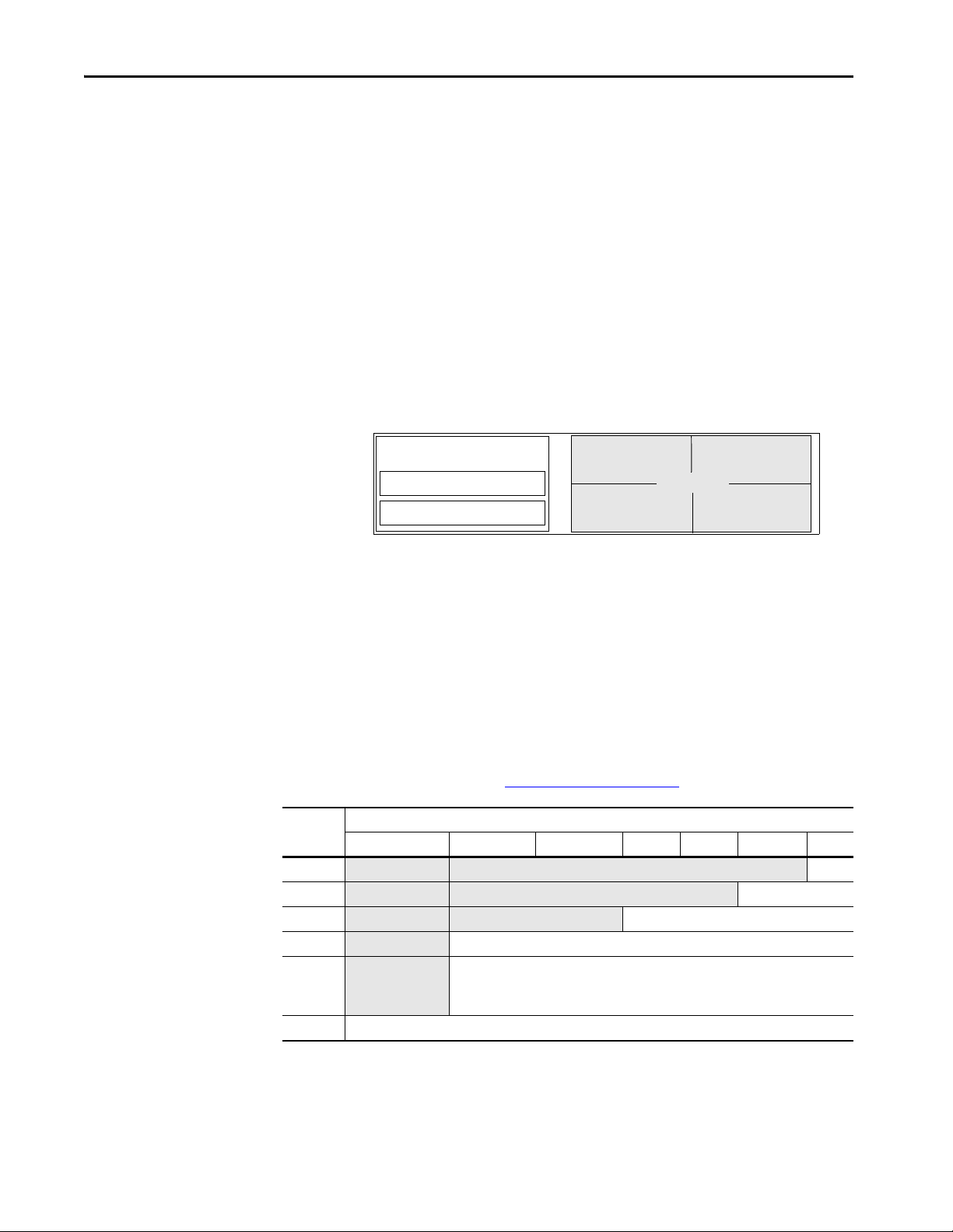
1756 ControlLogix 5570 controllers - Memory is separated into isolated sections.
Project Documentation Memor y
Comment descriptions
Alarm log
Extended tag properties
I/O Memory
Program source code
Tag data
HMI tag group lists
I/O data
I/O force tables
Message buffers
Produced/consumed tags
CompactLogix 5370 controllers - Memory is separated into isolated segments.
Logix
CPU
Logic and Data Memory
Comment descriptions
Alarm log
Extended tag properties
Project Documentation Memory
Characteristic CompactLogix 5370 Controllers and Compact GuardLogix 5370 Controllers
Armor CompactLogix 5370 Controllers and Armor Compact GuardLogix 5370 Controllers
Controller redundancy Back up via DeviceNet - CompactLogix 5370 L3 Controllers and Compact GuardLogix 5370 L3 controllers only
Logix Hot Backup - CompactLogix 5370 L3 Controllers only
Integrated motion EtherNet/IP
Conformal coating 1769-L30ERK,1769-L30ERMK, 1769-L33ERK, 1769-L33ERMK, 1769-L33ERMSK, 1769-L37ERMK, 1769-L37ERMSK,
1769-L38ERMK, 1769-L38ERMSK
Controller Memory
CompactLogix 5370 and Compact GuardLogix 5370 Controllers
The Logix CPU executes application code and messages. The backplane CPU
transfers I/O memory and other module data on the backplane. This CPU
operates independently from the Logix CPU, so it sends and receives I/O
information asynchronous to program execution.
TIP CPU usage is based on the number of devices in the I/O tree. About 6% of the CPU is used
for every 100 devices in the I/O tree.
The Logix CPU executes application code and messages.
Controller I /O Task Priorit y Communication Task Priority
CompactLogix 5370 6 12
Rockwell Automation Publication 1756-RM094K-EN-P - October 2020 23

Chapter 3 5570 Controllers and 5370 Controllers
Controller Connections
The controller uses a connection to establish a communication link between
two devices.
IMPORTANT The topics in this section apply only to ControlLogix 5570 and earlier
controllers, and CompactLogix 5370 and earlier controllers operation
Connections can be made to the following:
• Controller to local I/O modules or local communication modules
• Controller to remote I/O or remote communication modules
• Controller to remote I/O (rack-optimized) modules
• Produced and consumed tags
• Messages
• Access to programming software
• Linx-based software access for HMI or other software applications
The controllers have different communication limits.
Communication Attribute 1756-L7x ControlLogix 1756-L6x ControlLogix 1769 CompactLogix CompactLogix 5370 1768 CompactLogix
Connections 500 250 100 256 250
Cached messages 32 for messages and block transfers combined
Unconnected receive buffers 3
Unconnected transmit buffers Default 20 (can be increased to 40) Default 10 (can be increased to 40)
The limit of connections can ultimately reside in the communication module
you use for the connection. If a message path routes through a communication
module, the connection that is related to the message also counts toward the
connection limit of that communication module.
Controller Communication Device Supported Connections
ControlLogix 1756-CN2R, 1756-CN2RXT
1756-CN2/B
1756-CNB,1756 -CNBR 64 CIP connections depending on RPI, recommend that you use only 48 connections
1756-EN2F, 1756-EN2T, 1756-EN2TR,
1756-EN2TP, 1756-EN2TXT, 1756-EN3TR
1756-EN4TR CIP connected messages:
1756-ENBT
1756-EWEB
CompactLogix 5370 Built-in Ethernet ports See the CompactLogix 5370 Controllers User Manual, publication 1769-UM021, for information on how to
(1) There are 1000 explicit connections and 528 implicit connections.
100 CIP™ connections
(any combination of scheduled and message connections)
128 CIP connections
(any combination of scheduled and message connections)
256 CIP connections
128 TCP/IP connections
• 1000 I/O
(1)
•528
512 TCP/IP connections
128 CIP connections
64 TCP/IP connections
count EtherNet/IP nodes on the I/O Configuration section of the programming software.
24 Rockwell Automation Publication 1756-RM094K-EN-P - October 2020

5570 Controllers and 5370 Controllers Chapter 3
Determine Total Connection Requirements
The total connections for a controller include both local and remote
connections. Counting local connections is not an issue for CompactLogix
controllers. They support the maximum number of modules that are permitted
in their systems.
When designing your CompactLogix 5370 controllers, you must consider
these resources:
• EtherNet/IP network nodes
• Controller connections
For more information, see the CompactLogix 5370 Controllers User Manual,
publication 1769-UM021
The ControlLogix controllers support more communication modules than the
other controllers, so you must tally local connections to make sure that you stay
within the connection limit.
.
Use this table to tally local connections.
Connection Type Device Quantity x Connections per Module = Total Connections
Local I/O module (always a direct connection) x 1 =
SERCOS Motion module x 3 =
ControlNet communication module x 0 =
EtherNet/IP communication module x 0 =
DeviceNet communication module x 2 =
DH+/Remote I/O communication module x 1 =
DH-485 communication module x 1 =
Programming software access to controller x 1 =
Tot a l
IMPORTANT A redundant system uses eight connections in the controller.
Rockwell Automation Publication 1756-RM094K-EN-P - October 2020 25

Chapter 3 5570 Controllers and 5370 Controllers
The communication modules that you select determine how many remote
connections are available. Use this table to tally remote connections.
Connection Type Device Quantity x Connections per Module = Total Connections
Remote ControlNet communication module
Configured as a direct (none) connection
Configured as a rack-optimized connection
Remote EtherNet/IP communication module
Configured as a direct (none) connection
Configured as a rack-optimized connection
Remote device over a DeviceNet network
(accounted for in rack-optimized connection for local DeviceNet module)
Safety device on a DeviceNet or EtherNet/IP network x 2 =
Other remote communication adapter x 1 =
Distributed I/O module (individually configured for a direct connection) x 1 =
Produced tag and first consumer
Each additional consumer
Consumed tag x 1 =
Connected message (CIP Data Table read/write and DH+™) x 1 =
Block transfer message x 1 =
Linx-based software access for HMI or other software applications x 4 =
FactoryTalk® Linx software for HMI or other software applications x 5 =
Tot a l
x
0 or
1
x
0 or
1
x0 =
x2
1
=
=
=
System Overhead Percentage
The system overhead timeslice specifies the percentage of continuous task
execution time that is devoted to communication and background redundancy
functions.
• Message communication is any communication that you do not
configure through the I/O configuration folder of the project, such as
MSG instructions.
• Message communication occurs only when a periodic or event task is not
running. If you use multiple tasks, make sure that their scan times and
execution intervals leave enough time for message communication.
• System overhead interrupts only the continuous task.
• The controller performs message communication for up to 1 ms at a
time and then resumes the continuous task.
• Adjust the update rates of the tasks as needed to get the best trade-off
between executing your logic and servicing message communication.
System overhead functions include the following:
• Communicating with HMI devices and programming software
• Sending and responding to messages
• Alarm management processing
• Redundancy qualification
26 Rockwell Automation Publication 1756-RM094K-EN-P - October 2020
5570 Controllers and 5370 Controllers Chapter 3
Continuous Task Restarts
Periodic Task Rest arts
Continuous Task
10% CPU Overhead
Continuous Task
25% CPU Overhead
Peri odic Tas k
CPU Overhead
The controller performs system overhead functions for up to 1 ms at a time. If
the controller completes the overhead functions in less than 1 ms, it resumes
the continuous task. The following chart compares a continuous and periodic
task.
Example Description
Continuous task
10% CPU overhead
Continuous task
25% CPU overhead
Periodic task Placing the same code in a periodic tas k yields even more time for communication processing. The bottom example assumes that the
In the top example, the system overhead timeslice is set to 10%. Given 40 ms of code to execute, the continuous task completes the
execution in 44 ms. During a 60 ms period, the controller is able to spend 5 ms on communication processing.
By increasing the system overhead timeslice to 25%, the controller completes the continuous task scan in 57 ms. The controller spends
15 ms of a 60 ms time span on communication processing.
code is in a 60 ms periodic task. The code executes to completion and then goes dormant until the 60 ms, time-based trigger occurs.
While the task is dormant, all CPU bandwidth can focus on communication. Because the code takes only 40 ms to execute, the controller
can spend 20 ms on communication processing. Depending on the amount of communication to process during this 20 ms window, it can
be delayed as it waits for other modules in the system to process the data that was communicated.
The CPU timeslices between the continuous task and system overhead. Each
task switch between user task and system overhead takes additional CPU time
to load and restore task information. You can calculate the continuous task
interval as:
ContinuousTime=(100/SystemOverheadTimeSlice%) - 1
The programming software forces at least 1 ms of execution time for the
continuous task, regardless of the system overhead timeslice. This more
efficiently uses system resources because letting shorter execution times of the
continuous task exist means switching tasks more frequently.
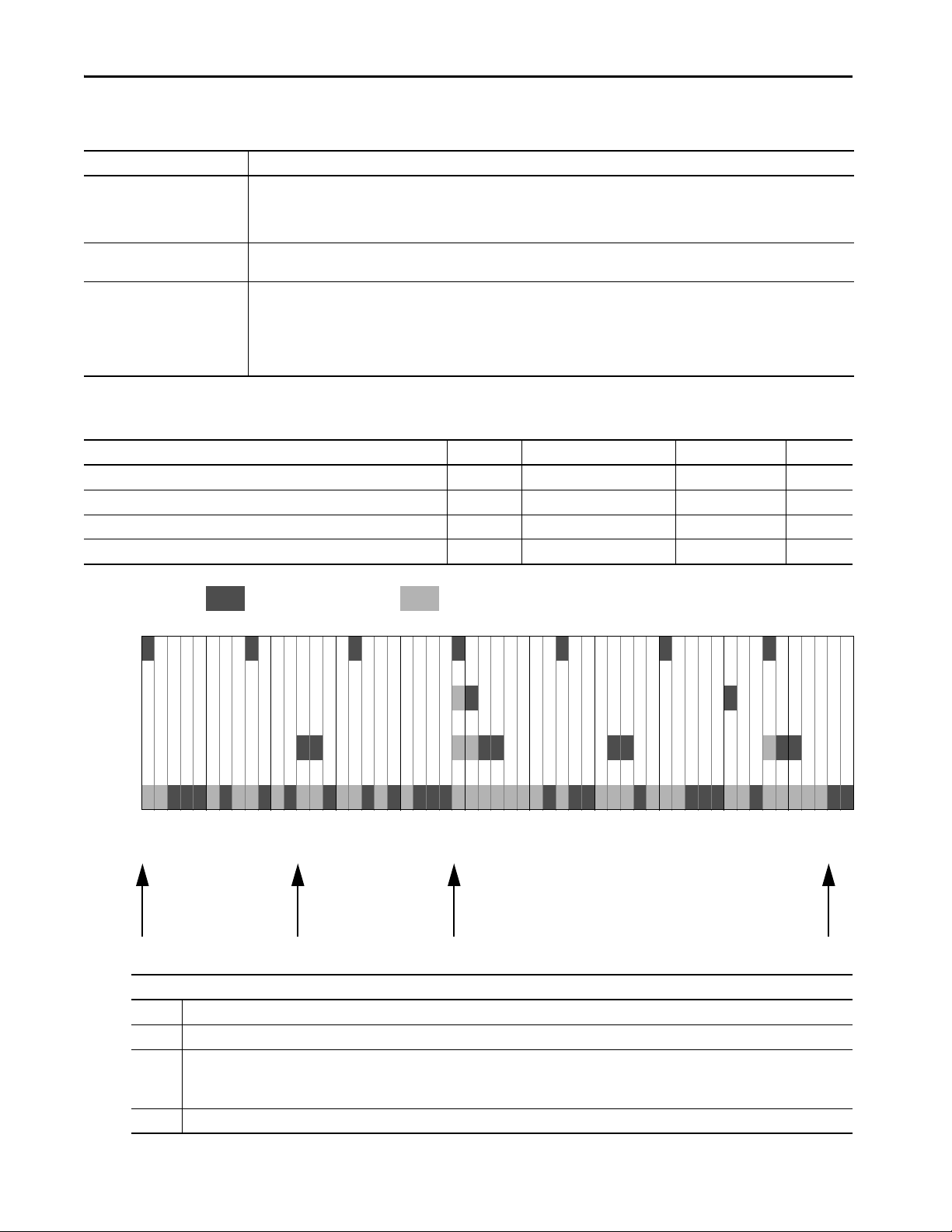
System Overhead Timeslice % Communication Execution (ms) Continuous Task Execution (ms)
10 1 9
20 1 4
33 1 2
50 1 1
66 2 1
80 4 1
90 9 1
Rockwell Automation Publication 1756-RM094K-EN-P - October 2020 27
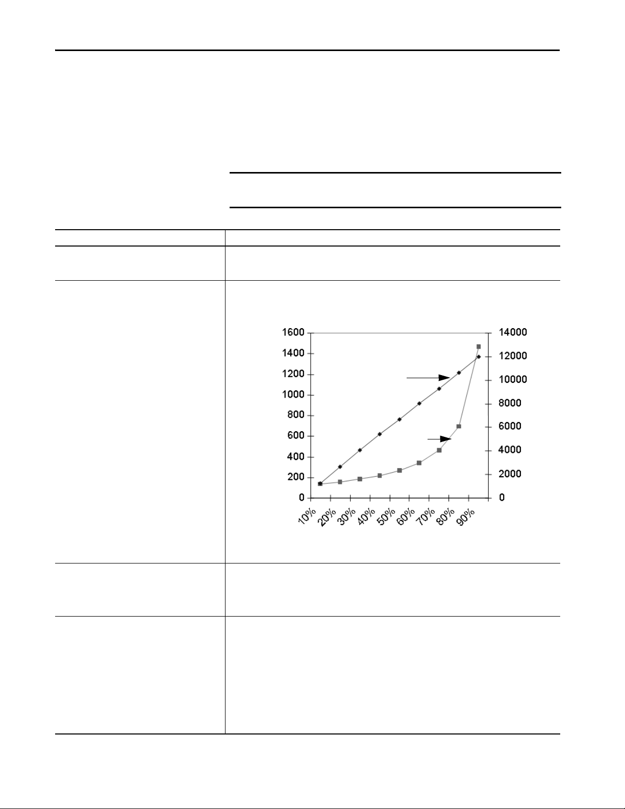
Chapter 3 5570 Controllers and 5370 Controllers
Program Scan
Time
Tag s Pe r
Second
System Timeslice %
Tags per Second
Program Scan Time in Milliseconds
Manage the System Overhead Timeslice Percentage
As the system overhead timeslice percentage increases, time that is allocated to
executing the continuous task decreases. If there is no communication for the
controller to manage, the controller uses the communication time to execute
the continuous task.
IMPORTANT System Overhead Time Slice does not apply to ControlLogix 5580 or
CompactLogix 5380 controllers.
Consideration Description
Continuous task always has at least 1 ms execution time The programming software forces the continuous task to have at least 1 ms of executio n time, regardless of the
Impact on communication and scan time Increasing the system overhead timeslice percentage decreases execution time for the continuous task while it
setting for the system overhead timeslice. This results in more efficient controller use because excessive swapping
between tasks uses valuable CPU resources.
increases communication performance.
Increasing the system overhead timeslice percentage also increases the amount of time it takes to execute a
continuous task - increasing overall scan time.
Unused portion of system overhead timeslice You can configure any unused portion of the system overhead timeslice to:
System overhead System overhead is the time that the controller spends on message communication and background tasks.
28 Rockwell Automation Publication 1756-RM094K-EN-P - October 2020
• Run the continuous task, which results in faster execution of application code and increases the variability of the
program scan.
• Process communication, which results in more predictable and deterministic scan time for the continuous task.
(This is for development and testing of an application to simulate communication.)
• Message communication is any communication that you do not configure through the I/O configuration folder of
the project, such as MSG instructions.
• Message communication occurs only when a periodic or event task is not running. If you use multiple tasks, make
sure that their scan times and execution intervals leave enough time for message communication.
• System overhead interrupts only the continuous task.
• The system overhead timeslice specifies the percentage of time (excluding the time for periodic or event tasks)
that the controller devotes to message communication.
• System overhead timeslice does not apply to ControlLogix 5580 and CompactLogix 5380 controllers.
• The controller performs message communication for up to 1 ms at a time and then resumes the continuous task.
• Adjust the update rates of the tasks as needed to get the best trade-off between executing your logic and servicing
message communication.
5570 Controllers and 5370 Controllers Chapter 3
Individual applications can differ, but the overall impact on communication
and scan time remains the same. The data is based on a ControlLogix5555
controller running a continuous task with 5000 tags (no arrays or user-defined
structures).
I/O Processing
Data Types
The 5370 controllers use a dedicated periodic task to process I/O data. This
I/O task:
• Operates at priority 6.
• Higher-priority tasks take precedence over the I/O task and can affect
processing.
• Executes at the fastest RPI you have scheduled for the system.
• Executes for as long as it takes to scan the configured I/O modules.
The controllers support IEC 61131-3 atomic data types. The controllers also
support compound data types, such as arrays, predefined structures (such as
counters and timers), and user-defined structures.
The Logix CPU reads and manipulates 32-bit data values. The minimum
memory allocation for data in a tag is 4 bytes. When you create a standalone tag
that stores data that is less than 4 bytes, the controller allocates 4 bytes, but the
data only fills the part that it needs.
For more information See Data Structures on page 75
Data Type Bits
64…32 31 16 15 8 7 1 0
BOOL
SINT Not allocated Allocated but not used -128…+127
INT
DINT Not allocated -2,147,483,648…2,147,483,647
REAL
LINT Valid Date/Time range is from 1/1/1970 12:00:00 AM coordinated universal time (UTC) to 1/1/3000 12:00:00 AM UTC
Not allocated Allocated but not used 0 or 1
Not allocated Allocated but not used -32,768…32,767
Not allocated -3.40282347E38…-1.17549435E
0
1.17549435E
-38
…3.40282347E38 (positive values)
-38
(negative values)
.
Rockwell Automation Publication 1756-RM094K-EN-P - October 2020 29

Chapter 3 5570 Controllers and 5370 Controllers
Programming Techniques
Programming Technique Consideration
Subroutines For Studio 5000 Logix Designer® Version 28 and later on 5570 and 5370 controllers:
Add-On Instructions For 5570 controllers or earlier, and 5370 controllers or earlier, there is no limit on nesting Add-On Instructions. However,
• JSR calls are limited to 40 input parameters and 40 output parameters.
• There is no limit on nesting JSR instructions. However, it is possible that too many nesting levels can cause the
controller to run out of memory and fault.
it is possible that too many nesting levels can cause the controller to run out of memory and fault.
For more information See Modular Programming Techniques on page 45.
Produced and Consumed Data
Messages
The controller supports:
•Total number of produced tags 127
• Maximum number of multicast produce tags out of the CompactLogix
Ethernet port 32
• Maximum number of consumed tags 250 (or controller maximum)
For more information See Produced and Consumed Data on page 71
The controller supports:
• As many outgoing, unconnected buffers as fit in controller memory.
Each buffer uses approximately 1.2 KB of I/O memory.
You can use a CIP Generic message instruction to increase the number
of unconnected buffers. See the Logix 5000™ Controllers Messages
Programming Manual, publication 1756-PM012
• Three incoming unconnected buffers
• 32 cached buffers, as of firmware revision 12 and later.
.
30 Rockwell Automation Publication 1756-RM094K-EN-P - October 2020

Chapter 4
Logic Execution
The controller operating system is a pre-emptive multitasking system that is
IEC 61131-3 compliant.
Tasks to configure controller execution A task provides scheduling and priority information for a set of one or more programs. You can configure tasks as either
Programs to group data and logic A task contains programs, each with its own routines and program-scoped tags. Once a task is triggered (activated), the programs
Routines to encapsulate executable code that
is written in one programming language
Decide When to Use Tasks,
continuous, periodic, or event.
that are assigned to the task execute in the order in which they are listed in the Controller Organizer.
Programs are useful for projects that multiple programmers develop. During development, the code in one program that uses
program-scoped tags can be duplicated in a second program to minimize the possibility of tag names colliding.
Tasks can contain programs and equipment phases.
Routines contain the executable code. Each program has a main routine that is the first routine to execute within a program. Use
logic, such as the Jump to Subroutine (JSR) instruction, to call other routines. You can also specify an optional program fault
routine.
Use these considerations to determine when to use a task, program, or routine.
Programs, and Routines
Comparison Task Program and Equipment Phase Routine
Quantity available Varies by controller (4, 6, 8, or 32) 32 program and equipment phases
Function Determines how and when code is executed Organizes groups of routines that share a
Use • Most code is expected to reside in a
continuous task
• Use a periodic task for slower processes or
when time-based operation is critical
• Use an event task for operations that
require synchronization to a specific event
Considerations • A high number of tasks can be difficult to
debug
• Can disable output processing on some
tasks to improve performance
• Tasks can be inhibited to help prevent
execution
• Do not configure multiple tasks at the same
priority
(combined) per task
100 for ControlLogix® controllers with V23 and
earlier
1000 programs/task for ControlLogix
controllers with V24 and later
common data area and function.
• Put major equipment pieces or plant cells
into isolated programs
• Use programs to isolate different
programmers or create reusable code
• Configurable execution order within a task
• Isolate individual batch phases or discrete
machine operations
• Data spanning multiple programs must be
controller-scoped or a program parameter.
• Listed in the Controller Organizer in the
order of execution
Unlimited number of routines per program
Contains executable code (relay ladder, function block
diagram, sequential function chart, or structured text)
• Isolate machine or cell functions in a routine
• Use the appropriate language for the process
• Modularize code into subroutines that can be called
multiple times
• Subroutines with multiple calls can be difficult to
debug
• Data can be referenced from program-scoped and
controller-scoped areas
• Calling many routines impacts scan time
• Listed in the Controller Organizer as Main, Fault,
and then alphabetically
Rockwell Automation Publication 1756-RM094K-EN-P - October 2020 31

Chapter 4 Logic Execu tion
Specify Task Priorities
Each task in the controller has a priority level. A higher priority task (such as 1)
interrupts any lower priority task (such as 15). The continuous task has the
lowest priority; periodic or event tasks always interrupt continuous tasks.
The controller has these types of tasks.
Priority User Task Description
Highest — CPU overhead - general CPU operations
— Motion planner - executed at coarse update rate
— Safety task - safety logic
— Redundancy task - communication in redundant systems
— Trend data collection - high-speed collection of trend data values
Priority 1 Event/Periodic User defined
Priority 2 Event/Periodic User defined
Priority 3 Event/Periodic User defined
Priority 4 Event/Periodic User defined
Priority 5 Event/Periodic User defined
Priority 6 Event/Periodic User defined
1769 CompactLogix™ controllers process I/O as a periodic task based on the chassis RPI setting
Priority 7 Event/Periodic User defined
Priority 8 Event/Periodic User defined
Priority 9 Event/Periodic User defined
Priority 10 Event/Periodic User defined
Lowest Priorit y 11 Event/Periodic User defined
Priority 12 Event/Periodic User defined
CompactLogix communication and scheduled connection maintenance
Priority 13 Event/Periodic User defined
Priority 14 Event/Periodic User defined
Priority 15 Event/Periodic User defined
Continuous Lowest priority task. Interrupted by all other tasks including system overhead timeslice (if
applicable.)
If a periodic or event task is executing when another is triggered, and both tasks
are at the same priority level, the tasks execute in 1 ms increments until one of
the tasks completes execution.
32 Rockwell Automation Publication 1756-RM094K-EN-P - October 2020

Logic Execution Chapter 4
Manage User Tasks
If you want logic to execute Use this task Description
All of the time Continuous task The continuous task runs in the background. Any CPU time that is not allocated to other operation s
• At a constant period (such as every 100 ms)
• Multiple times within the scan of your other logic
Immediately when an event occurs Event task An event task performs a function only when a specific event (trigger) occurs. Whenever the
You can configure these user tasks.
or tasks is used to execute the continuous task.
• The continuous task runs all of the time. When the continuous task completes a full scan, it
restarts immediately.
• A project does not require a continuous task. If used, there can be only one continuous task.
Periodic task A periodic task performs a function at a specific time interval. Whenever the time for the periodic
task expires, the periodic task:
• Interrupts any lower priority tasks.
• Executes one time.
• Returns control to where the previous task left off.
trigger for the event task occurs, the event task:
• Interrupts any lower priority tasks.
• Executes one time.
• Returns control to where the previous task left off.
The user tasks that you create appear in the Tasks folder of the controller. The
predefined system tasks do not appear in the Tasks folder and they do not
count toward the task limit of the controller.
Pre-defined Tasks in ControlLogix and CompactLogix Process Controllers
PlantPAx system release 5.0 adds process controllers to the Logix 5000 family
of controllers. The process controllers offer additional capabilities that are
targeted for DCS applications.
The Task folder contains a project structure that consists of four pre-defined
periodic tasks:
• Fast (100 ms) – For control fast loops, such as liquid flow or pressure
with related transmitters and pump drives
• Normal (250 ms) – For discrete control, such as motors, pumps, and
valves
• Slow (500 ms) – For level, temperature, analysis loops, phases, and batch
sequencing
• System (1000 ms) – For slow change temperature control and general
controller operations, such as messaging or status
Rockwell Automation Publication 1756-RM094K-EN-P - October 2020 33
Chapter 4 Logic Execu tion
Considerations that Affect Task Execution
Consideration Description
Motion planner The motion planner interrupts all other tasks, regardless of their priority.
Output processing At the end of a task, the controller performs output processing for the output modules in your system. This processing depends on the
Too many tasks If you have too many tasks, then the following can occur:
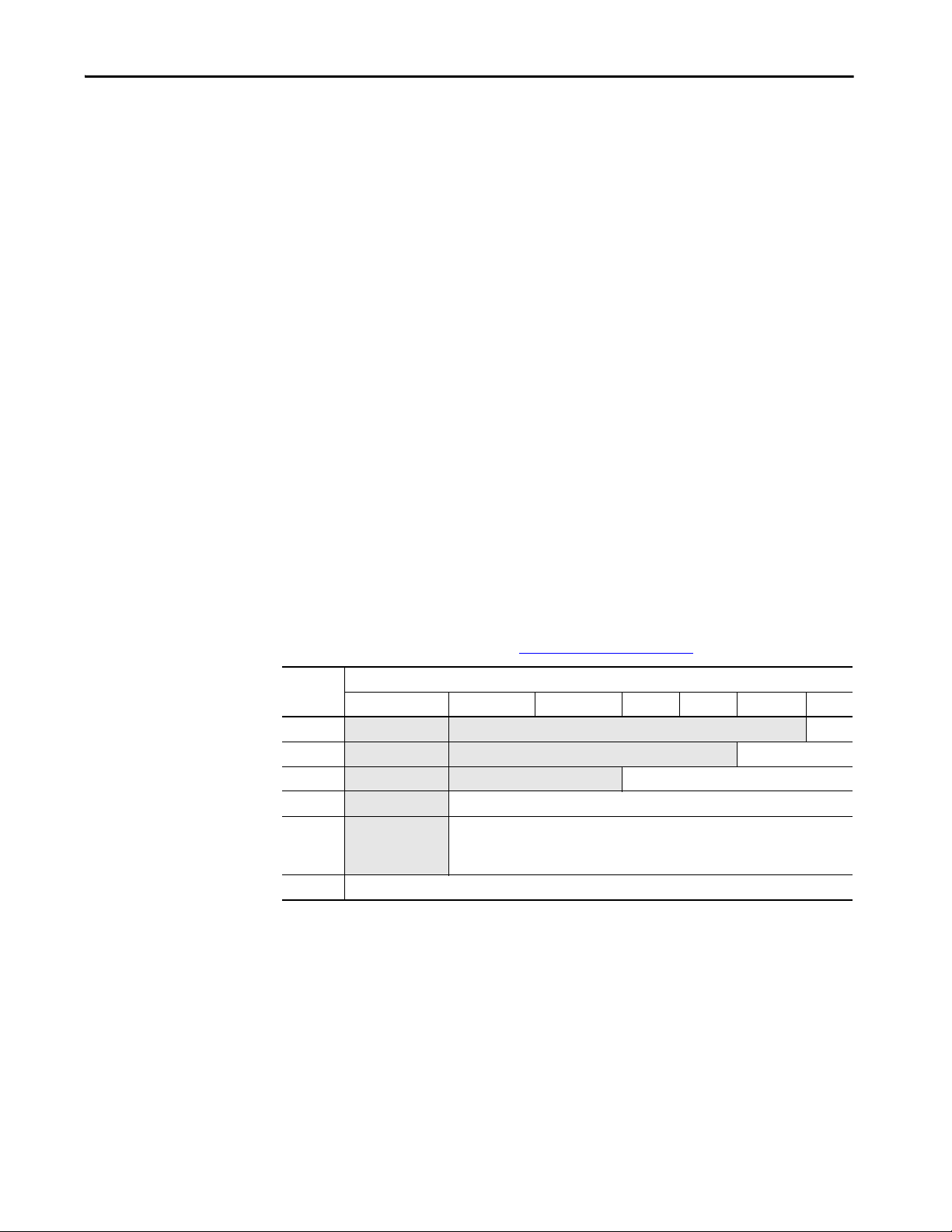
Table 1 - Example Task Execution
Task Priority Period Execution Time Duration
Motion planner — 8 ms (course update rate) 1 ms 1 ms
Event task 1 1 — 1 ms 12 ms
Periodic task 1 2 12 ms 2 ms 2
Continuous task — — 20 ms 48 ms
• The number of axes and coarse update period for the motion group affect how long and how often the motion planner executes.
• If the motion planner is executing when a task is triggered, the task waits until the motion planner is done.
• If the coarse update period occurs while a task is executing, the task pauses to let the motion planner execute.
number of output connections that are configured in the I/O tree.
• Continuous task can take too long to complete.
• Other tasks can experience overlaps. If a task is interrupted too frequently or too long, it must be triggered again to complete its
execution .
• Controller communication can be slower.
• If your application is designed for data collection, try to avoid multiple tasks.
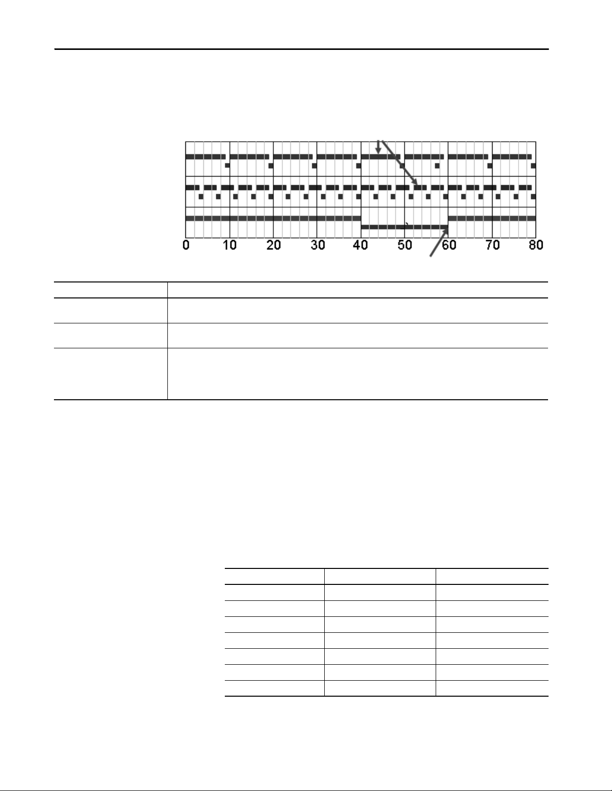
This example depicts the execution of a project with these tasks.
4ms
Motion
Planner
Event
Tas k 1
Perio dic
Tas k 1
Continuous
Tas k
Legend: Ta sk e xec ute s. Task is interrupted (suspended).
5 101520253035404550
123 4
Description
1 Initially, the controller executes the motion planner and the I/O task (if one exists).
2 The period for periodic task 1 expires (12 ms), so the task interrupts the continuous task.
3 The triggers occur for event task 1.
Event task 1 waits until the motion planner is done.
Lower priority tasks experience longer delays.
4 The continuous task automatically restarts.
34 Rockwell Automation Publication 1756-RM094K-EN-P - October 2020

Logic Execution Chapter 4
Configure a Continuous Task
Configure a Periodic Task
Configure an Event Task
When you create a project in the programming software, the Main Task is
configured as a continuous task.
• A controller supports one continuous task, but a continuous task is not
required.
• You can configure the task to update output modules at the end of the
continuous task.
• You can change the continuous task to either a periodic or event task.
A periodic task executes automatically based on a preconfigured interval. You
can configure whether the task updates output modules at the end of the
periodic task. After the task executes, it does not execute again until the
configured time interval has elapsed.
An event task executes automatically based on a trigger event occurring, or if a
trigger event does not occur in a specific time interval. You configure whether
the task updates output modules at the end of the task. After the task executes,
it does not execute again until the event occurs again. Each event task requires
a specific trigger.
Trigger Description
Module Input Data State Change A remote input module (digital or analog) triggers an event task that is based on the change of state (COS) configuration for the module.
Consumed Tag Only one consumed tag can trigger a specific event task. Use an Immediate Output (IOT) instruction in the producing controller to signal the
Axis Registration 1or 2 A registration input triggers the event task.
Axis Watch A watch position triggers the event task.
Motion Group Execution The coarse update period for the motion group triggers the execution of both the motion planner and the event task. Because the motion
EVENT Instruction Multiple EVENT instructions can trigger the same task.
Enable COS for only one point on the module. If you enable COS for multiple points, a task overlap of the event task can occur.
• The ControlLogix sequence of events modules (1756-IB16ISOE, 1756-IH16ISOE) use the Enable Coordinated System Time (CST) Capture
feature instead of COS.
• The embedded input points on the 1769-L16ER-BB1B, 1769-L18ER-BB1B, 1769-L18ERM-BB1B, 1769-L18ERM-BB1B, and
1769-L19ER-BB1BKmodules can be configured to trigger an event task when a COS occurs.
production of new data.
planner interrupts all other tasks, it executes first.
For more information on event tasks, see:
• Logix 5000™ Controllers Common Procedures Programming Manual,
publication 1756-PM001
• Using Event Tasks with Logix 5000 Controllers,
publication LOGIX-WP003
Rockwell Automation Publication 1756-RM094K-EN-P - October 2020 35

Chapter 4 Logic Execu tion
Guidelines to Configure an Event Task
Guideline Description
Place the I/O module being used to trigger an event
in the same chassis as the controller.
Limit events on digital inputs to one input bit on a
module.
Set the priority of the event task as the highest
priority on the controller.
Limit the number of event tasks. Increasing the number of event tasks reduces the available CPU bandwidth and increases the chances of task overlap.
Placing the I/O module in a remote chassis adds more network communication and processing to the response time.
All inputs on a module trigger one event, so if you use multiple bits you increase the chance of a task overlap. Configure the
module to detec t change of state on the trigger input and turn off the other bits.
If the priority of the event task is lower than a periodic task, the event task has to wait for the periodic task to complete
execution.
Additional Considerations for Periodic and Event Tasks
Consideration Description
Amount of code in the event task Each logic element (for example, rung, instruction, or structured text construct) adds to scan time.
Task priority If the event task is not the highest priority task, a higher priority task can delay or interrupt the execution of the event task.
CPS and UID instructions If one of these instructions is active, the event task cannot interrupt the currently executing task. (The task with the CPS or UID.)
Motion planner The motion planner takes precedence over event or periodic tasks
Trends Trend data collection takes precedence over event or periodic tasks.
Output processing You can disable output processing at the end of a task to reduce the amount of task processing time. The Controller Organizer displays
whether outputs processing is disabled.
Access the Module Object
The MODULE object provides status information about a module. To select a
particular module object, set the Object Name operand of the GSV/SSV
instruction to the module name. The specified module must be present in the
I/O Configuration section of the controller organizer and must have a
device name.
With the Studio 5000 Logix Designer® application, version 24.00.00 and later,
you can access the MODULE object directly from an Add-On Instruction.
Previously, you could access the MODULE object data, but not from within
an Add-On Instruction.
You must create a Module Reference parameter when you define the Add-On
Instruction to access the MODULE object data. A Module Reference
parameter is an InOut parameter of the MODULE data type that points to the
MODULE Object of a hardware module. You can use module reference
parameters in both Add-On Instruction logic and program logic.
For more information on the Module Reference parameter, see the Logix 5000
Controllers Add-On Instructions Programming Manual,
publication 1756-PM010
36 Rockwell Automation Publication 1756-RM094K-EN-P - October 2020
, and the Logix Designer application online help.

Logic Execution Chapter 4
The Path attribute is available with Logix Designer application, version
24.00.00 and later. This attribute provides a communication path to the
module.
For more information on the attributes available in the MODULE object, see
the Logix 5000 Controllers General Instructions Reference Manual,
publication 1756-RM003
.
Develop Application Code in Routines
Section of Code Represents Language to Use
Continuous or parallel execution of multiple operations (not sequenced) Ladder Diagram(LD)
Boolean or bit-based operations
Complex logical operations
Message and communication processing
Machine interlocking
Operations that service or maintenance personnel can interpret to troubleshoot the machine or process.
Servo motion control
Continuous process and drive control Function block diagram (FBD)
Loop control
Calculations in circuit flow
High-level management of multiple operations Sequential function chart (SFC)
Repetitive sequences of operations
Batch process
Motion control sequencing (via sequential function chart with embedded structure text)
State machine operations
Complex mathematical operations Structured text (ST)
Specialized array or table loop processing
ASCII string handling or protocol processing
Each routine contains logic in one programming language. Choose a
programming language that is based on the application.
Rockwell Automation Publication 1756-RM094K-EN-P - October 2020 37

Chapter 4 Logic Execu tion
Benefits
• Uses more memory
• Fastest execution time because all tag references
are defined before runtime
• Easiest to maintain because rung animation
matches tag values
• Requires more time to create and modify
Comparison of Programming Languages
Comparison Relay Ladder Logic Function Block Diagram Sequential Function Chart Structured Text
Instruction categories • Boolean
• General and trig math
• Timers and counters
• Array management
•Diagnostic
• Serial port and messaging
•ASCII manipulation
•Motion control
Editor style • Graphical rungs
• Unlimited rungs
Monitoring • Rung animation
• Data value animation
•Force status
Comments • Tag
•Rung
• General and trig math
•Timers and counters
•Bitwise logical
• Advanced process
• Advanced drive
• Graphical, free-form drawing
•Unlimited sheets
• Output and input pin data value
animation
•Tag
•Text box
• Step/action with embedded
structured text
• Transition with structure text
comparisons
• Simultaneous and selection
branches
• Stop element
• Graphical, free-form drawing
• Unlimited grid space
• Active steps animation
• Auto display scroll
• Branch/transition force status
•Tag
•Text box
• Embedded structured text
comments that are stored in CPU
• General and trig math
•Timers and counters
•Bitwise logical
• Array management
•Diagnostic
•ASCII manipulation
• Specialty CPU control
•Motion control
• Advanced process
• Advanced drive
•Textual
• Unlimited lines
•Tag watch pane
•Context coloring
•Multi-line
• End if line
• Comments that are stored in CPU
Programming Methods
The capabilities of the controllers make different programming methods
possible. There are trade-offs to consider when selecting a programming
method.
Inline Duplication
Write multiple copies of the code with different tag references.
38 Rockwell Automation Publication 1756-RM094K-EN-P - October 2020
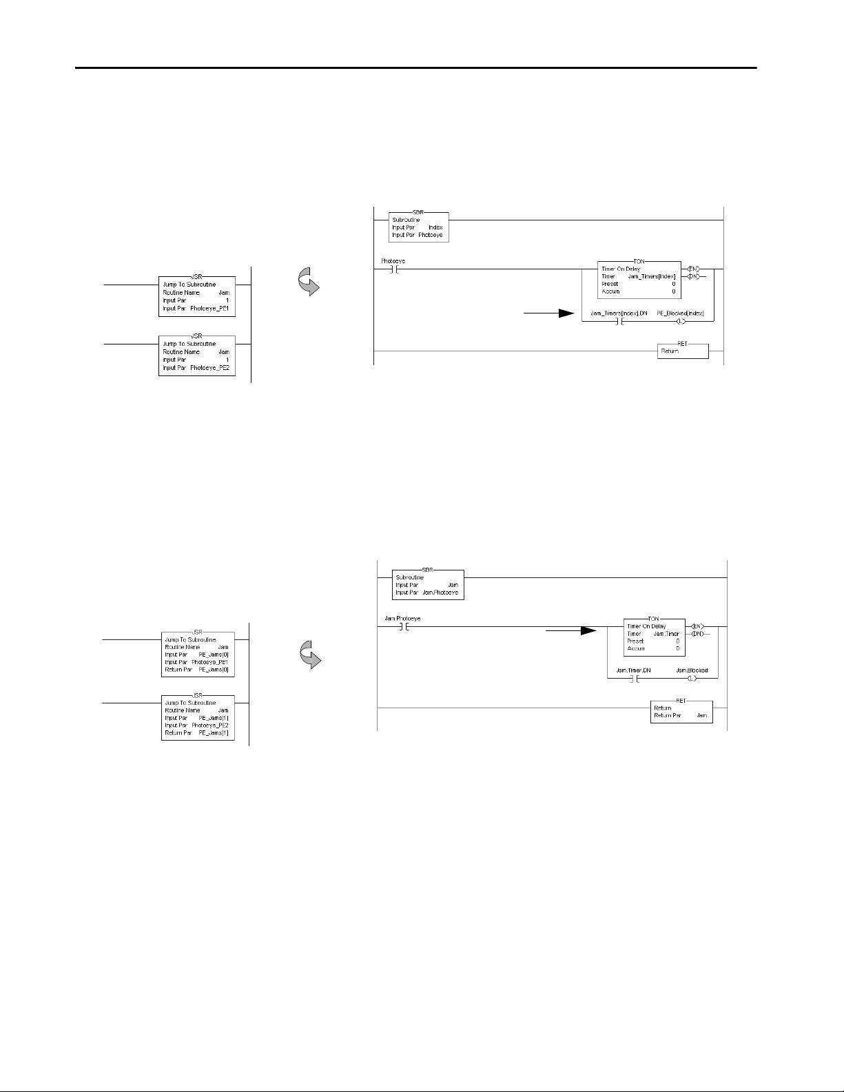
Logic Execution Chapter 4
The JSR instruction
passes the index.
Each indexed reference adds
to scan time.
Benefits
• One copy of code is faster to develop
• Slowest execution time because all tag references
are calculated at runtime
• Can be difficult to maintain because the data
monitor is not synchronized to execution
The JSR instruction
passes all control
instance data.
A user-defined structure
consolidates co ntrol data.
Direct reference to a loca l
copy of data.
Benefits
• One copy operation can occur faster than multiple
index offsets
• Minimizes the need to calculate array offsets at
runtime
• The amount of code increases, but so do the
benefits
• Can be difficult to maintain because the data
monitor is not synchronized to execution
Indexed Routine
Write one copy of code and use indexed references to data stored in arrays.
Buffered Routine
Copy the values of an array into tags to directly reference these buffer tags.
Rockwell Automation Publication 1756-RM094K-EN-P - October 2020 39

Chapter 4 Logic Execu tion
Controller Prescan of Logic
On transition to Run mode, the controller prescans logic to initialize
instructions. The controller resets all state-based instructions, such as outputs
(OTE) and timers (TON). Some instructions also perform operations during
prescan. For example, the ONSR instruction turns off the storage bit.
For information on prescan, see the following resources:
• Logix 5000 Controllers General Instructions Reference Manual,
publication 1756-RM003
.
• Logix 5000 Controllers Process Control and Drives Instructions
Reference Manual, publication 1756-RM006
.
During prescan, input values are not current and outputs are not written.
Prescan Affects Description
Relay ladder logic The controller resets non-retentive I/O and internal values.
Function block diagram logic Along with resetting non-retentive I/O and internal values, the controller also
Structured text logic The controller resets bit tags and forces numeric tags to zero .
Sequential function chart logic Embedded structured text follows the same rules as listed previously.
clears the EnableIn parameter for every function block diagram.
Use the bracketed assignment operator ([:=]) to force a value to be reset during
prescan.
If you want a tag that is left in its last state, use the non-bracketed assignment
operator (:=).
Prescan differs from first scan in that the controller does not execute logic
during prescan. The controller executes logic during first scan. The controller
sets S:FS for one scan:
• During the first scan that follows prescan.
• During the first scan of a program when it has been uninhibited.
• Each time a step is first scanned (when step.FS is set). You can view the
S:FS bit being set only from the logic that is contained in actions that
execute during the first scan of their parent step (N, L, P, and P1).
Add-On Instruction Prescan Logic
An Add-On Instruction prescan logic executes after the main logic executes in
Prescan mode. Use the prescan logic to initialize tag values before execution.
For example, set a PID instruction to Manual mode with a 0% output before its
first execution.
When an Add-On Instruction executes in Prescan mode, any required
parameters have their data passed.
• Values are passed to Input parameters from their arguments in the
instruction call.
• Values are passed out of Output parameters to their arguments defined
in the instruction call.
40 Rockwell Automation Publication 1756-RM094K-EN-P - October 2020

Logic Execution Chapter 4
Controller Postscan of SFC Logic
SFCs support an automatic reset option that performs a postscan of the actions
that are associated with a step once a transition indicates that the step is
completed. Also, every Jump to Subroutine (JSR) instruction causes the
controller to postscan the called routine. During this postscan:
• Output energize (OTE) instructions are turned off and non-retentive
timers are reset.
• In structured text code, use the bracketed assignment operator ([:=]) to
have tags reset.
• In structured text code, use the non-bracketed assignment operator (:=)
to have tags that are left in their last state.
• Selected array faults, that is, 4/20 and 4/83, can be suppressed. When
the fault is suppressed, the controller uses an internal fault handler to
clear it. Clearing the fault causes the postscan process to skip the
instruction containing the fault and continue with the next instruction.
This occurs only when SFC instructions are configured for automatic
reset.
Add-On Instruction Postscan Logic
When an Add-On Instruction is called by logic in an SFC Action and the
Automatic Reset option is set, the Add-On Instruction executes in Postscan
mode. An Add-On Instruction postscan routine executes after the main logic
executes in Postscan mode. Use the postscan logic to reset internal states and
status values or to disable instruction outputs when the SFC action completes.
Rockwell Automation Publication 1756-RM094K-EN-P - October 2020 41

Chapter 4 Logic Execu tion
Timer Execution
Timers in the controllers store off a portion of the real-time clock each time
they are scanned. The next time through, they compare this stored value
against the current clock and then adjust the ACC value by the difference.
The controller uses native 32-bit data, so there is more space to store the time.
The timer stores 22 bits at 1 ms/bit, which equates to 69.905 minutes
(2**22 / 1000 ms per second / 60 seconds per minute) of padding before a
timer overlaps.
If program execution skips timers, it appears as if the timers pause. Actually, the
timers are overrunning themselves. Depending on when the timer logic next
executes, the lost time varies ranges from 0…69.905 minutes.
Program execution can skip executing timers due to the following:
• Subroutine not being called
•Jumping over code
•SFC action
• Inactive SFC step
• Event or periodic task not executing
• Equipment phase state routines
SFC Step Timer Execution
An SFC step timer stores the clock time each time the step executes. On
subsequent scans of the step, the controller compares the current clock time
with the last scan and updates the step timer’s ACC by the difference.
When you pause an SFC and then release the SFC, the step timer jumps
forward by the duration of the pause. If you want a step timer to remain at its
position during a pause:
• Latch a recovery bit when the chart pause is released.
• Add an action to the step to store the step timer’s.ACC value and restore
that value when the pause recovery bit is set.
42 Rockwell Automation Publication 1756-RM094K-EN-P - October 2020

Logic Execution Chapter 4
Edit an SFC Online
When you edit an SFC online, the software initially makes the changes in the
offline project. When you accept the changes, they are downloaded to the
controller. If you transition the controller to test or untest edits, the controller
resets the SFC and starts execution at the initial step. If you edit an SFC online,
do the following:
• Plan when you test or untest edits to coincide with the SFC executing
the initial step.
• Place structured text logic in subroutines to minimize the impact of
online edits.
• Use an SFR instruction to shift SFC execution to the desired step
programmatically.
In some cases, this can result in the SFC being out of sync with the equipment.
Program logic in the initial step to check the last state and use an SFR
instruction to change to the appropriate step, if needed. One method is to set
an index number in an action of each step. Then when the restart occurs, use
the SFR instruction to jump to appropriate step based on the index value.
As of firmware revision 18, the following online edits to an SFC no longer reset
the SFC to the initial step:
• Modified structured text in actions and transitions
• Physically moved steps, actions, and transitions on SFC sheets without
changing the wiring
• Added, deleted, or modified text and description boxes
• Modified indicator tags
Rockwell Automation Publication 1756-RM094K-EN-P - October 2020 43

Chapter 4 Logic Execu tion
Notes:
44 Rockwell Automation Publication 1756-RM094K-EN-P - October 2020

Chapter 5
Modular Programming Techniques
Modular programming guidelines support the delivery of standardized
programming structures, conventions, configurations, and strategies. The goal
of modular programming is to provide consistency.
• Faster and easier development of application software
• Faster and easier testing of application software
• More reliable application software
• Improved maintenance and operation of application software
• Improved interoperability with other equipment and systems
This chapter applies to these controllers, and where applicable, the controllers
are known as:
Controller Family Includes these controllers
5580 controllers ControlLogix® 5580 and GuardLogix® 5580 controllers
5380 controllers CompactLogix™ 5380 and Compact GuardLogix 5380 controllers
5570 controllers ControlLogix 5570 and GuardLogix 5570 controllers
5370 controllers CompactLogix 5370 and Compact GuardLogix 5370 controllers
5480 Controllers CompactLogix 5480 Controllers
Rockwell Automation Publication 1756-RM094K-EN-P - October 2020 45

Chapter 5 Modular Programming Techniques
Guidelines for Code Reuse
Guideline Description
Use user-defined data types (UDTs) to group data. Within a UDT:
Use Add-On Instructions to create standardized modules
of code for reuse across a project.
Use program parameters to share data between
programs.
Use partial import/export programs, routines, Add-On
Instructions, and code segments to create libraries of
reusable code.
Use subroutines to reuse code within a program. Subroutines:
• You can mix data types.
• The tag names that you assign self-document the structure.
Use an Add-On Instruction to:
• Encapsulate specific or focused operations, such as a Motor or Valve action. A Conveyor or Tank action is better
managed as a routine.
• Create extensions to the base controller instructions. For example, create an Add-On Instruc tion to execute an
SLC™ 500 or PLC controller instruction not available in the Logix 5000™ controllers.
• Encapsulate an instruction from one language for use in another language. For example, create a function block
PIDE instruction for use in relay ladder.
Program parameters:
• Are publicly accessible outside of the program.
• Support external HMI external access on an individual basis for each parameter.
Direct access lets the user reference program parameters in logic without configuring parameters in the local
program. For example, if Program A has an output parameter that is called Tank_Level, Program B can reference the
Tank_Level parameter in logic without creating a corresponding parameter to connect to Program A.
Partial import and export of routines and programs:
• Provides more control over the scope of what is extracted from the project.
• Provides reusable code for la rger machine, cell, or unit control.
• Promotes collaboration between multiple engineers, code standardization, and reuse.
The export .L5X file includes all per tinent information, including program configuration, code, user-defined data
types, tags, and descriptions, in an XML-formatted, ASCII text file. Use partial import/export to:
• Distribute code separately from the project .ACD file.
• Edit and create programs and routines by using other editing tools.
• Can be created and used in standard and safety applications.
• Pass User-Defined Structures (UDT).
• Pass all input and output Parameters by value.
• Subroutines require the most overhead to pass parameters when called.
• Can only be called from within the program they reside.
46 Rockwell Automation Publication 1756-RM094K-EN-P - October 2020

Modular Programming Techniques Chapter 5
Area/Unit + Type Controller Name:
Mixing:ControlLogix
Project in controller Mixing_CLX,
Major Revision 1, Minor Revision 02
Application Name:
Mixing_CLX_C2_092.ACD
Interprocessor communication tag IPC_
Input tag I_
Output tag O_
Remote I/O tag RIO_
Control module class tag Device ID_
Equipment module class tag EM_
Equipment phase class tag EP_
Naming Conventions
The following conventions are guidelines to help make an engineering library
more reusable by other developers. These guidelines also help the resulting
applications have a more consistent look and feel.
• Names that are meaningful (and readable) to people who use the
application as a later date are most effective.
• Names use controller memory and have limited length, so keep them
short by using abbreviations and acronyms. Use mixed case rather than
underscore characters to indicate words.
• When you use acronyms, use those that are common or provided by
industry standards.
Names for controller logic components must follow these guidelines.
• The name must start with a letter, either upper or lower case
• The name can contain as many as 40 characters; any mix of upper case
letter, lower case letters, numbers, and underscore characters
• Case is not significant. The controller interprets Mix_Tank the same
and mix_tank. However, the software displays the case as entered
• Underscores are significant. The controller interprets AB_CD as unique
from A_BCD
• You cannot have two or more underscore characters in a row
• The name cannot end with an underscore.
Component Name Recommendations
Controller Are a, unit, or units the controlle r controls, underscore, t ype of control ler
Controller project Controller name, the letter C, 1-digit major revision number, underscore, 2-digit minor revision number
Tag Prefix with the abbreviation of the type of tag
Example:
Example:
Increment the minor revision number for any documented engineering change according to the code in the controller
(for example, the code for minor process or equipment changes).
Increment the major revision number for any documented engineering change according to the code in the controller
that implements a design change (for example, code that enhances or reduces controller functionality).
Examples:
Rockwell Automation Publication 1756-RM094K-EN-P - October 2020 47

Chapter 5 Modular Programming Techniques
Analog input AI
Analog output AO
Discrete input DI
Discrete output DO
Analog input/output combination AIO
Discrete input/output combination DIO
Analog/discrete input/output combination ADIO
Serial data SIO
Motion data MIO
DeviceNet® data DNET
EtherNet/IP™ data ENET
ControlNe t® CNET
Mixer123 Controller, Local chassis, Slot 4, Analog
Output
Module Name: M123_CLX_L00_S04_AO
Mixer123 Controller, Local chassis, Slot 12,
Discrete Output
Module Name: M123_CLX_L00_S12_DO
Mixer123 Controller, Remote chassis #1, Slot 1,
Analog Input
Module Name: M123_CLX_R01_S01_AI
Mixer123 Controller, Remote chassis #1, Slot 2,
Analog Output
Module Name: M123_CLX _R01_S02_AO
Mixer123 Controller, Remote chassis #2, Slot 5,
Discrete Input
Module Name: M123_CLX _R02_S05_DI
Mixer123 Controller, Remote chassis #2, Slot 6,
Discrete Output
Module Name: M123_CLX _R02_S06_DO
Mixer123 Controller, Local chassis, Slot 5,
Remote I/O
Module Name: M123_CLX _R02_S06_RIO
Component Name Recommendations
I/O or communication module Controller name, underscore, abbreviation of rack location (L=local, R=remote), underscore, the letter S, 2-digit slot
number, underscore, abbreviation of function
Example Functions:
48 Rockwell Automation Publication 1756-RM094K-EN-P - October 2020
Examples:

Modular Programming Techniques Chapter 5
Parameter Name Prefixes
Programming structures, such as Add-On Instructions and programs support
parameters for passing values. The convention for prefixes is to abbreviate the
function of the parameter to three letters and an underscore, followed by
additional text to clarify the specific function.
Parameter Function Prefix Description
Command Cmd_ Designates a command input, either from the operator via the HMI or from the program.
Examples:
• Cmd_Reset: Clear faults and reset the process
• Cmd_JogServo: Jog a servo axis
• Cmd_FillTank: Fill a tank with a liquid
Configuration Cfg_ Designates a configuration value for the structure. Enter from the HMI or as part of a recipe.
Examples:
• Cfg_JogDirection: Selects the direction a servo jogs: 0=Positive, 1=Negative
• Cfg_BulkFill: Selects the fill rate to use: 0=Slow Rate, 1=Fast Rate
• Cfg_UserUnits: Selects the measure of volume to use: 0=mm, 1=m, 2=gal
•Cfg_EnableInterlocks: Enable interlock functionality
• Cfg_EnablePermissive: Enable permissive functionality
Status Sts_ Status of the process within the structure.
Examples:
• Sts_Alarm: An alarm condition (such as a HI/LOW alarm) exists within the process
• Sts_ER: An error with an instruction execution within the process has been detected
• Sts_IndexComplete: The servo index move within the process has completed
• Sts_FillInProcess: The tank filling process is underway
Error Err_ If the Sts_ER bit is on, the Err_ parameter indicates the actual error. This can be either a bit level or value level indication.
Alarm Alm_ If the Sts_Alm bit is on, the Alm_ parameter indicates which alarm is occurring. This can be either a bit-level or value -
Input Inp_ Real-time data used to drive the process. Designates a connection either to a real input point, a control device, or to dat a
Output Out_ Real-time data driven from the process. Designates a connection to a real output point, a control device, or to data sent
Reference Ref_ Complex data structures that combine input and output data.These structures pass data into a structure, where some
• Bit level error recording supports multiple errors simultaneously, but can require a large number of indicators to
support all error states.
• Value-based error annunciation supports a large quantity of errors within one indicator. However, this approach
requires that errors are annunciated one at a time.
Examples:
• Err_Value: A nonzero value indicates an error condition
• Err_PCamCalcFault: Indicates that an error has occurred in an MCCP
level indication.
• Bit-level alarming supports multiple alarms simultaneously, but can require a large number of indicators to support
all alarm states.
• Value-based alarm annunciation supports a large quantity of alarms within one indicator. However, this approach
requires alarms to be annunciated one at a time.
Examples:
• Alm_Value: A nonzero value indicates an alarm condition
• Alm_TankHI: Indicates that a HI level condition has been detected within a tank
received from other processes.
Examples:
• Inp_ServoPosition: Variable providing the input value for a position of a servo
• Inp_ServoRegistrationPosition: Input of the registration position of the servo
• Inp_InterlockOK: Input indicating external interlocks are met
• Inp_TankLevel: Variable providing the analog input for a tank’ level
• Inp_TankLevelFillRate
to other processes.
Examples:
• Out_GlueGun1: Output signal to turn of Glue Gun 1
• Out_ServoCorrectionDistance: Output of a ser vo registration correction distance
• Out_OverflowValve: Output signal to open the Overflow Valve
• Out_TankLevelError: Output of a difference between target and actual fill level of a tank
process is performed. The results are then loaded back into the structure to be passed out of Add-On Instruction for use
elsewhere.
Example:
Ref_PositionCamRecovery: Provides the data set for calculating a Position Cam with all offsets factored in, and the
resulting Position Cam Profile to run in an MAPC instruction
Rockwell Automation Publication 1756-RM094K-EN-P - October 2020 49

Chapter 5 Modular Programming Techniques
Parameter Function Prefix Description
Parameter Par_ Variables that are received from an external source that can be internal or external to the program.
Examples:
• Par_MachineSpeed: Provides a machine's running speed
• Par_TargetFillLevel: Provides a tank's target fill level
Set point Set_ Variables received from an operator or HMI and are not part of an external source.
Examples:
• Set_MachineMaxSpeed: Provides the setting for a machine's maximum permissible speed
• Set_TankHILevel: Provides the setting for a tank's HI alarm limit
Value Val_ Designates a value that might not be the primary output of the structure.
Report Rpt_ Designates a value that is typically used for reporting.
Information Inf_ Non-functional data such as a revision level or name for displaying a faceplate.
Ready Rdy_ Command-ready bits that are typically Booleans calculated inside the control routines to reflect whether the routine let
Program Command
(optional)
Operator Command
(optional)
PCmd_ Command input for commands typically issued by the application program.
OCmd_ Command input for commands typically issued by the operator via the HMI.
states change commands. Used with HMI faceplates to enable or disable command buttons.
Examples:
• PCmd_ProgReq - Request for Program Mode made by the application (as opposed to Cmd_ProgProgReq)
• PCmd_AutoReq - Request for Auto Mode made by the application (as opposed to Cmd_ProgAutoReq)
Examples:
• OCmd_ProgReq - Request for Program Mode made by the operator (as opposed to Cmd_OperProgReq)
• OCmd_AutoReq - Request for Auto Mode made by the operator (as opposed to Cmd_OperAutoReq)
Guidelines for Subroutines
Guideline Description
Input and Return parameters depend on the
subroutine logic.
Pass complete timers in and out of subroutines. If a subroutine needs a timer, pass the complete timer tag to the subroutine as an input and return the complete timer
Create a user-defined tag to pass large numbers Input
and Output parameters
Data types must match For each parameter in an SBR or RET instruction, use the same data type (including any array dimensions) as the
Follow these parameter guidelines for subroutines.
If the subroutine needs to know the previous state of any Return parameters (the values are used elsewhere in the
project), these values should also be Input parameters:
• If the subroutine contains latch/unlatch logic (holding circuits), intended outputs of the subroutine should be passed
into and returned from the subroutine.
• If the subroutine does not contain latch/unlatch logic, intended outputs of the subroutine only need to be returned
from the subroutine.
tag as an output. Store the timer in a buffer tag outside of the subroutine.
Create and pass a UDT if you have several Input and Output parameters to save on execution time. The more parameters
that you pass, the fewer nested JSRs you can perform.
corresponding parameter in the JSR instruction. Using different data types can produce unexpected results.
50 Rockwell Automation Publication 1756-RM094K-EN-P - October 2020

Modular Programming Techniques Chapter 5
Guidelines for User-defined Data Types
A UDT lets you organize or group data logically, so that all of the data
associated with a device (such as a pressure transmitter or variable-frequency
drive) can be grouped.
• You can mix data types, such as real or floating point values, counters,
timers, arrays, Booleans, and other UDTs, within one UDT.
• You can copy a UDT from one project to another, and even from one
Logix controller type to another.
• A UDT is self-documenting based on the tag names you assign, and
provides a logical representation of parts or subsystems.
Naming Conventions for User-Defined Data Types
Element Description
Prefix_ UDT_
UDT name Func tion or purpose of the UDT
Examples:
Inventory tracking tag UDT_InventoryTracking
Clean-in-place system UDT_CIP
Two-state valve control module in control module UDT_CMV2S
Water addition in equipment module UDT_EM
UDT Member Order
The order in which elements are listed in the UDT can have a significant
impact on memory use if several BOOL, INT, or SINT elements are defined.
Memory is allocated in 4-byte (32-bit) increments, and every DINT, REAL,
STRING, or sub-UDT element always start at the beginning of a 4-byte
boundary.
Rockwell Automation Publication 1756-RM094K-EN-P - October 2020 51

Chapter 5 Modular Programming Techniques
For example, if the first element defined is a BOOL, it uses the first 4 bytes
allocated to the UDT. Other BOOLs can be assigned immediately following
without consuming any more memory, until the first 4 bytes are consumed.
However, if the next element is a DINT, the DINT element allocates another 4
bytes even though the BOOL occupies only a single bit in the first 4 bytes. So
for this example, the 31 bits of memory between the BOOL and the start of
the DINT are allocated but are not accessible.
• UDT memory is allocated in 4-byte increments.
• Elements that occupy 4 bytes or more always start at a 4-byte boundary.
These include DINT, REAL, STRING, any UDT, or any other
complex data structure.
• Elements of smaller data types (BOOL, SINT, or INT) start on the next
byte boundary that matches its size, so that all the data types in the UDT
are fully contained in their respective 4-byte increments. For example,
INT elements start on 2-byte boundaries, SINT elements follow at the
next byte, and BOOL elements in succession occupy consecutive bits
within a byte.
In the following example, the UDT on the left, UDT_Tank, has members
arranged by function without regard for memory usage. This makes sense in
the context of implementation, because members toward the top are ordinarily
used in the software code.
However, the disjointed listing of data types in UDT_Tank consumes 25%
more memory than the example UDT on the right, UDT_TankPacked. In
UDT_TankPacked, the BOOL members are grouped according to their
functionality, with the input BOOLs grouped at the top and the output
BOOLs grouped at the bottom. As a result, the data type size is reduced from
80 bytes to 64 bytes.
52 Rockwell Automation Publication 1756-RM094K-EN-P - October 2020

Modular Programming Techniques Chapter 5
For 64 bit data types such as LINT, ULINT, and LREAL, it is necessary for
proper operation that these be aligned on 8 byte boundaries.
The following two examples show how this alignment is accomplished within
UDTs.
Data Type Byte Offset or Size
BOOL 0
PAD 7
LINT 8
Data Type Byte Offset or Size
DINT 0
PAD 4
LREAL 8
Guidelines for Add-On Instructions
An Add-On Instruction encapsulates commonly used functions or device
controls. It is not intended for use as a high-level hierarchical design tool. Once
an Add-On Instruction is defined in a project, it behaves similarly to the builtin instructions that are already available in the programming software. The
Add-On Instruction appears on the instruction toolbar and in the instruction
browser.
Guideline Description
Create Add-On Instructions in relay ladder, function
block diagram, or structured text languages.
An Add-On Instruction supports parameters:
•Input (copied in)
• Output (copied out)
• InOut (passed by reference)
Create and modify offline only. Online operation supports monitoring.
Supports all Add-On Instructions and most built-in instructions. Excludes JSR/SBR/RET, JXR, FOR/BRK (relay ladder), SFR,
SFP, SAR, IOT, and EVENT instructions.
GSV/SSV instructions in an Add-On Instruction cannot reference the Module, Message, Axis, Motion Group, or Coordinate
System class names.
Add-On Instructions support function block, relay ladder, and structured text programming languages. Each of the
Add-On Instruction logic areas can be any language. For example, the main logic can be function block and the prescan
logic can be relay ladder.
You can create safety Add-On Instructions in a safety task.
• For Version 24 and earlier, you are limited to 512 total parameters: Input parameter + Output parameter + local tags
(no limit on the number of InOut parameters)
• For Version 28 and later, you are limited to 40 InOut parameters, but no limit on the number of Input or Output
parameters)
• 2 MB maximum data instance (parameters and locals)
• Alarm, axis, axis group, coordinate system, message, motion group, and produced/consumed tags must exist at the
program or controller scope and passed as an InOut parameter
• Can inc lude references to cont roller-scoped tags, program-scoped tags, and immediate values.
• Input and Output parameters are limited to atomic (BOOL, SINT, INT, DINT, REAL) data types. Use the InOut parameter
for LINT, user-defined, and structure data types.
• DINT data types provide optimal execution.
• Default values of parameters and local tags are used to initialize the data structure when a tag is created of the
instruction’s data type. When an existing parameter or local tag's default value is modified, the existing tag instances
for that instruction are not updated. When a parameter or local tag is added to the instruction definition, the tag's
default value is used in the existing tags.
Modifications to Add-On Instructions are made offline. Make changes once to the Add-On Instruction definition to affect
all instances.
Rockwell Automation Publication 1756-RM094K-EN-P - October 2020 53

Chapter 5 Modular Programming Techniques
Guideline Description
An Add-On Instruction executes like a routine. A task with a higher execution priority can interrupt an Add-On Instruction. Use a UID/UIE instruction pair to make sure
The code within an Add-On Instruction can access
data that is specified only via parameters or defined as
local.
Use optional Scan mode logic to set up, initialize, or
reset the Add-On Instruction code.
Apply code signatures to Add-On Instructions for
revision control.
an Add-On Instruction’s execution is not interrupted by a higher priority task.
If you have many parameters or specialized options, consider multiple Add-On Instructions
Calling many Add-On Instructions impacts scan time
Copy the local data to a parameter if you want to programmatically access it outside of an Add-On Instruction.
An Add-On Instruction can have logic along with the main logic for the instruction.
• Prescan logic executes on controller startup.
• Postscan logic executes on SFC Automatic reset.
• EnableInFalse logic executes when rung condition is false.
Add-On Instructions can be sealed with a code signature. Use the code signature for revision control and to identify any
changes. For safety controllers, the signature can be used to get TÜV certification for a safety Add-On Instruction. For
more information, see the Logix 5000 Controllers Add-On Instructions Programming Manual, publication 1756-PM010.
54 Rockwell Automation Publication 1756-RM094K-EN-P - October 2020

Add-On Instruction Design Concepts
PCam profile display PCamProfileDisplay
PCam profile display PCamProfileDisplay_AOI
To be sure that specific data is passed into or out of the Add-On Instruction,
use a required parameter. A required parameter must be passed as an argument
in order for a call to the instruction for verification. To pass a required
parameter in ladder diagrams and in structured text, specify an argument tag
for the parameter.
• In a function block diagram, required Input parameters and Output
parameters must be wired.
• In a ladder diagram, InOut parameters must have an argument tag.
• If a required parameter lacks an associated argument, the routine that
contains the call to the Add-On Instruction does not verify.
Naming Conventions for Add-On Instructions
Component Name Recommendations
Add-On Instruction Start with the application name.
Add a variant name, is applicable.
Capitalize the first letter in all words in the name.
Example:
Modular Programming Techniques Chapter 5
Suffix with underscore AOI, if space permits.
Example:
Comparison of Subroutines and Add-On Instructions
Comparison Subroutine Add-On Instructions
Accessibility Within program (multiple copies) Anywhere in controller (single copy)
Parameters Pass by value Pass by value or reference via InOut
Numeric parameters No conversion, you must manage Automatic data type conversion for Input and Output parameters
InOut parameters must match declared type exactly
Parameters data types
Parameter che cking
Data encapsulation All data at program or controller scope (accessible to anything) Local data is isolated (only accessible within instruction)
Monitor/debug
Supported programming languages
Callable from FBD, LD, SFC, ST FBD, LD, SFC, ST
Protection Locked and View Only Locked and View Only
Documentation Routine, rung, textbox, line Instruction description, revision information, vendor, rung, textbox,
Execution performance • JSR/SBR/RTN add overhead
Atomic, arrays, structures • Atomic data types as In or Out parameters
None, you must manage Verification checks
Logic that is animated with mixed data from multiple calls Logic that is animated with data from one calling instance
FBD, LD, SFC, ST FBD, LD, ST
• All data is copied
• LINT, user-defined, and structure data types as InOut parameters
line, extended help
• Call is more efficient
• InOut passed by refe rence
Rockwell Automation Publication 1756-RM094K-EN-P - October 2020 55

Chapter 5 Modular Programming Techniques
Comparison Subroutine Add-On Instructions
Memory use Compact • Call requires more memory
Edit
Import/export All routines are imported/exported in the full project .L5K file
Both code and data can be modified offline and online in a
running controller
(protected routines can be excluded or encrypted)
Individual LD rungs and references and tags/UDTs can be
imported/exported via the .L5X file
• All references n eed additional memo ry
Code modifications are limited to offline in the project file and require
a new download
Data values associated can be modified online and offline
All Add-On Instructions are imported/exported in the full project .L5K
file (protected instructions can be excluded or encrypted)
Individual Add-On Instruction definitions and code are imported/
exported via the .L5X fil e
Comparison of Partial Import/Export and Add-On Instructions
Comparison Partial Import/Export Add-On Instructions
Logic Any program, equipment phase, routine, Add-On Instruction, or user-
defined data type in the project can be imported/expor ted via .L5X file.
Controller accessibility Impor t on-line with a running controller:
• Add programs, routines, and Add-On Instructions
• Existing programs and routines can be replaced
• Create tags and UDTs
• Name collisions are detected automatically and you are prompted to
rename or bind to existing components
• The data values in the controller are maintained and new tags have their
values initialized from the import file
Logic checking You resolve conflicts on import. The software verifies the components that you add to Add-On
Data Editing member definitions of an Add-On Instruction maintains the values
that are assigned to the parameters when:
• Inserting, adding, or deleting members
• Rearranging (moving) members
• Renaming members
• Changing the data types of members
Values for members that are both renamed and moved in the same
operation are not to be maintained.
Create once (single copy) and use anywhere in the same
controller project.
Existing Add-On Instructions can only be edited offline.
New Add-On Instructions can be created online or offline.
Instruction as you create it.
Local data is isolated (only accessible within the instruction).
56 Rockwell Automation Publication 1756-RM094K-EN-P - October 2020

Modular Programming Techniques Chapter 5
Guidelines for Program Parameters
Program parameters define a data interface for programs to facilitate data
sharing. Data sharing between programs can be achieved either through
pre-defined connections between parameters or directly through a special
notation. Unlike local tags, all program parameters are publicly accessible
outside of the program. Additionally, HMI external access can be specified on
individual basis for each parameter.
Standard (non-Safety) parameters can be created, edited, and deleted while
online with the controller. The following exceptions apply:
• Parameters cannot be deleted while online if they are connected/bound
to other parameters, or if the control logic references them.
• InOut parameters cannot be deleted while online
• InOut bindings can only be changed online through a Partial Import
Online (PIO) operation
A safety parameter cannot be connected with or bound to a standard
parameter or controller-scoped tag. A safety connection cannot be created,
modified, or deleted in a safety-locked project. Input, Output, and Public
parameters support the External Access attribute. InOut parameters do not.
Program Parameter Description
Input • Input parameters (including members) can only support ONE connection. Only one source can be delivering the value to the input parameter.
Output • Output parameters (including members) can support multiple connections. For example, lets assume you have a BOOL input parameter in
InOut • InOut parameters can only support ONE connection. You cannot configure connections to any member of an InOut parameter.
Public • Public parameters can support MULTIPLE connections. You can configure connections to the base Public parameter or any member of a Public
• Input Parameter values are refreshed before each scan of a program. The values do not change during the logic execution so you do not need to
write code to buffer inputs.
• A program can write to its own input parameters.
• Data values for Output parameters that are connected to controller scope tags or Public parameters are copied after the scan o f a program. In a
project with multiple tasks, the data copy for a parameter that is of type BOOL, SINT, INT, DINT, LINT, or REAL will not be interrupted. A task
switch can interrupt the data copy from an Output parameter to a controller scope tag or Public parameter, or any other predefined or userdefined data type.
Program A and Program B named Input1a and Input1b. You can connect an output parameter in Program C to Input1a AND Input1b. As stated
earlier, this is often referred to as fanning.
• Output Parameter values are refreshed AFTER each scan of a program. Updated output parameter values are NOT available to the parameters
connected to that output parameter until the program execution is complete.
• Output parameters that are connected to Public parameters or controller scope tags are copied (pushed) at the end of the program execution.
• An Output parameter can ONLY be connected to an InOut parameter if both the Output and InOut parameters are configured as Constants.
• InOut parameters are passed by REFERENCE, which means they simply point to the base tag. In other words, when an InOut parameter is used
in logic, the current value of the parameter that is connected to the InOut Parameter is used.
• An InOut parameter can ONLY be connected to an Output parameter if both the Output and InOut parameters are configured as Constants. See
the tool tip for Output Parameters for a more detailed explanation.
• InOut parameters CANNOT be changed online, unless using the Partial Import Online (PIO).
parameter. This includes User-Defined Structures.
• Public parameters are updated when the source is updated. In other words, when a Public parameter value updates, it is immediately available
to any higher priority tasks that are connected to that parameter.
• Public parameters can be aliased to Controller Scope Tags. If this functionality is desired, remember that the alias update is asynchronous to
program execution. The public parameter contains the real-time value of the controller scope tag.
Rockwell Automation Publication 1756-RM094K-EN-P - October 2020 57

Chapter 5 Modular Programming Techniques
Comparison of Program Parameters and Add-On Instructions
Comparison Program Parameters Add-On Instructions
Accessibility Within program (multiple copies) Anywhere in controller (single copy)
Parameters Input / Output (pass by value), InOut (pass by reference), Public (pass
Numeric parameters • Automatic data type conversion for Input and Output parameters
Parameters data types
Parameter che cking
Data encapsulation All data at program or controller scope (accessible to anything).
Monitor/debug
Supported programming
languages
Callable from FBD, LD, SFC, ST FBD, LD, SFC, ST
Protection — Locked and View Only
Documentation — Instruction description, revision information, vendor, rung, textbox,
Execution performance • Programs can talk directly and exchange data between them.
Memory use Compact. One Public parameters can be connected or bound to
Edit
by value)
• InOut parameters must match declared type exactly
Atomic, strings, arrays, structures • Atomic data types as In or Out parameters
None, user must manage Verification checks
Programs can talk directly and exchange data between them. Local
tags remain private to the Program. Cannot access Local Tags, only
the parameters.
Online editable. Logic that is animated with data from one calling instance
FBD, LD, SFC, ST FBD, LD, ST
• InOut passed by reference
multiple Input, Output or InOut parameters to form a shared memory
space.
Online editable, and supports sub- element connections. Copy / Paste
Programs without disturbing parameter configuration.
Input / Output (pass by value), InOut (pass by reference)
• Automatic data type conversion for Input and Output parameters
• InOut parameters must match declared type exactly
• LINT, user-defined, and structure data types as InOut parameters
Local data is isolated (only accessible within instruction)
line, extended help
• Call is more efficient
• InOut passed by reference
• Call requires more memory
• All refe rences need additional memo ry
Code modifications are limited to offline in the project file and require
a new download
Data values associated can be modified online and offline
Compare Controller
Organizer and Logical
The Controller Organizer presents program logic how the controller executes
the logic. The Logical Organizer is configurable to present program logic how
the user views the system.
Organizer
58 Rockwell Automation Publication 1756-RM094K-EN-P - October 2020

Chapter 6
Structure Logic According to Standards
The ANSI/ISA-88.01-1995 (R2006) standard is the most recognized and
broadly adopted standard for modular equipment control. Complementing
ISA-88.01 is the ISA-TR88.00.02 technical report, which is also known as
PackML. The ISA-TR88.00.02 technical report comes from the Organization
for Machine Automation and Control (OMAC). The OMAC provides
examples of how to apply ISA-88.01 in discrete manufacturing segments.
ISA refers to the International Society of Automation, an ANSI recognized
Standards Development Organization (SDO).
• ISA-88 refers to a specific set of ISA standards, of which ISA88.01 is
asubset.
• SP88 refers to the ISA working member group responsible for the creation
and publication of the ISA-88 standards.
ISA-88 provides these models to define and understand the automation control
requirements for manufacturing plants.
Model Description
Physical The physical model (also known as the equipment model) describes a hierarchical organization of equipment and the
Procedural The procedural model describes a multi-tiered, hierarchical model that defines the process capability and automation
basic control capabilities that are associated with that organization. The physical model is a representation of the
equipment in the plant that makes the product.
control in relation to the Physical Model to perform a task. The procedural model is a representation of how to use the
equipment (described in the physical model) to make the product.
Rockwell Automation Publication 1756-RM094K-EN-P - October 2020 59

Chapter 6 Structure Logic According to Standards
Enterprise
Site
Area
Process Cell
Unit
Equipme nt
Module
Control
Module
Control
Module
Control
Module
Control
Module
Control
Module
Control
Module
Control
Module
Control
Module
Equipme nt
Module
Equipme nt
Module
Physical Model
The physical model (also known as the equipment model) describes a
hierarchical organization of equipment and the basic control capabilities that are
associated with that organization. The physical model is a representation of the
equipment in the plant that is used to make the product.
The physical model defines the automation components within a given
environment, and determines modular areas and component interactions.
The physical model shows that an enterprise can contain multiple sites, and a site
can contain multiple areas, down to the equipment modules and control modules
Physical Model Component Description
Enterprise The company that owns the facilities.
Site The location of one facility.
Process cell A collection of one or more units that are linked together to perform a task or multiple tasks of the process for one or more
60 Rockwell Automation Publication 1756-RM094K-EN-P - October 2020
that carry out the manufacturing process
products in a defined sequence. A process cell contains the units, equipment modules, and control modules that are
needed to make one or more batches.

Structure Logic According to Standards Chapter 6
Physical Model Component Description
Unit (or machine) A collection of related equipment modules and control modules that execute one or more processing activities. The unit
Equipment module A functional group of control modules, equipment modules, or both that execute a finite number of activities. The
Control module Control module: A regulating device, state-oriented device, or combination thereof (typically, a collection of sensors,
corresponds to the logical grouping of mechanical and electrical assemblies that historically has been called a machine.
The term unit can apply to either a single -function machine or a multi-functional machine.
primary purpose of control in an equipment module is to coordinate the functions of other equipment modules and
lower-level control modules. A process cell, unit, operator, or another equipment module can command an equipment
module.
An equipment module can be part of A unit, or a standalone equipment group can include an equipment module in a
process cell. If engineered as a standalone equipment grouping, an equipment module can be an exclusive-use resource
or a shared-use resource. The equipment module combines all necessary physical processing and control equipment that
is required to perform the manufacturing process. The finite tasks that an equipment module is designed to carry out
defines the scope of the equipment module.
The terms control module and equipment module apply to the physical equipment as well as to the equipment entity.
The following are examples of equipment modules.
• A valve matrix used for material transfer between units (shared resource of process cell)
• A level control for a tank (equipment module within a specific unit)
• A vertical form-fill-seal machine’s ‘sealing jaws control’ (equipment module within a discrete unit)
actuators, and other control modules) that is operated as a single device. Control that is normally found at this level
directly manipulates actuators and other control modules. A control module can direct commands to other control
modules, or to actuators that have been configured as part of the control module. Control of the process is affected
through the equipment-specific manipulation of control modules and actuators. The control module is the lowest level
grouping of equipment in the physical model that can carry out basic control.
The following are examples of control modules.
• An individual sensor or actuator
• A state-oriented device that consists of an on/off automatic block valve with position feedback switches and that is
operated via the set point of the device
• A header that contains several on/off automatic block valves that coordinates the valves to direct flow to one or
several destinations based on the set point directed to the header CM
• A servo-controlled electronic gear or cam function (that is, a discrete unit), including its interlock and permissives.
The following are typical control modules in a programming library:.
• Analog output
• Analog input with scaling and alarms
• Reversing motor
• Variable speed drive
• Solenoid-operated 2-state valve
• Motor-operated 2-state valve
• PID with standard modes and deviation alarms
Rockwell Automation Publication 1756-RM094K-EN-P - October 2020 61

Chapter 6 Structure Logic According to Standards
Equipment Modules
Control Modules
Process Cell
Physical Model
Unit
Site: My Site Site Name: M
Area: Manufacturing Building (102) Area Name: M102
Separate a Process Unit into Equipment Modules and Control Modules
To create a modular control program, start with one of these approaches.
• Identify the control modules in the process. Then group the control
modules into equipment modules to be supervised and coordinated by
procedural controls.
• Determine the units (typically vessels containing a single batch at a time).
Then determine the equipment modules (such as ingredient addition
equipment, agitating equipment, thermal jacket temperature control
equipment, and transfer out equipment) by reviewing the related
equipment, piping, and instrumentation on a process and instrumentation
diagram (P&ID). Then determine the control modules that are related to
the equipment states that must be controlled (such as motors, valves, or
other process control loops).
One way to organize application logic in the Controller Organizer is to create a
separate folder for each unit.
Component Name Recommendations
Site Shor t, preferably single character abbreviation, all upper case, of the formal name of the site
Area Building number prefixed by a site name, but with no separating underscore
62 Rockwell Automation Publication 1756-RM094K-EN-P - October 2020
Physical Model Naming Conventions
Example:
Example:

Component Name Recommendations
Cell: Mixing Cell Name: A102_MIX_123
Unit Class: Mix Tank Unit Name: (Machine)
Unit Class: Packer Unit Name: UN_Pckr
Unit Instance: Mix Tank 1234 Unit Name: A102_MT1234
Machine Instance: Packaging Machine 1234 Unit Name: A102_PKR1234
Unit Instance Program Name: A102_UN02_MT1234
Machine Instance Program Name: A102_UN02_PKR1234
Unit Instance Tag Name: MT1234
Machine Instance Tag Name: PKR1234
EM Instance: Mix Tank 1234 Vessel Agitator EM Name: MT1234_EM_Agitate
EM Instance: Packager 1234 Bag Forming EM Name: PKR1234_EM_BagForming
CM Class: PID Control Loop CM Name: CM_PID
CM Class: Cylinder CM Name: CM_Cylndr
CM Instance: Temperature Controller 01 CM Name: TC_01
CM Instance: Cylinder 01 CM Name: CY01
Cell Two- to three-character abbreviation of the formal name of the cell
Prefix with an area name and a single underscore (optional)
Example:
Unit In a unit class, prefix the unit name with UN and an underscore
Example:
In a unit instance, use the unit identification from the piping and instrumentation diagram (P&ID)
All uppercase letters; use underscored instead of dashes
Prefix the unit name with the area name, separated from the unit name by a single underscore
Example:
In a unit program instance, add the unit identifier between the area name and the unit name
Example:
Structure Logic According to Standards Chapter 6
In a unit tag instance, prefix the tag with the unit name
Example:
Equipment module Area name, underscore, letters EM, underscore, function abbreviation
All uppercase letters
Example:
Control Module In a control module class, prefix the name with CM and an underscore
Example:
In a control module instance, use all uppercase letters
Area name, underscore, unit name, underscore, instrument name, loop sequence number
Example:
Rockwell Automation Publication 1756-RM094K-EN-P - October 2020 63
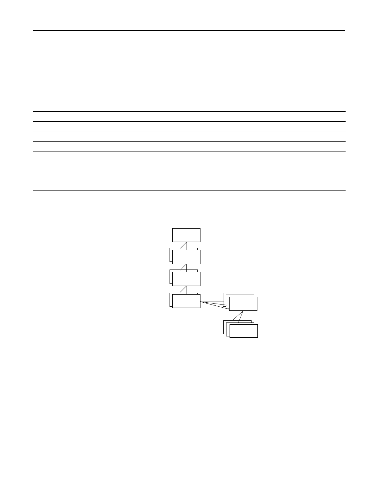
Chapter 6 Structure Logic According to Standards
Phase
Operation
Unit
Procedure
Process
Cell
Equipme nt
Module
Control
Module
Procedural Model
The procedural model describes a multi-tiered, hierarchical model that defines
the process capability and automation control in relation to the physical model to
perform a task. The procedural model is a representation of how to use the
equipment (described in the physical model) to make the product.
The procedural control that is laid out in the procedural model directs the
equipment components, via the component interfaces, to perform the specific
tasks out of the available capabilities, needed to produce a given product.
Procedural Model Component Description
Procedure The general strategy for production within a process cell. A procedure is composed of unit procedures.
Unit procedure A production sequence. Unit procedures are composed of operations.
Operation The single sequence necessary for the initiation, organization, and control of phases. Operations are composed of phases.
Phase The lowest level of a procedure that can accomplish an action.
The intent of a phase is to cause or define a process-oriented action, while the set of steps in the phase is equipmentspecific.
• A phase can be subdivided into smaller parts.
• A phase can issue one or more commands or cause one or more actions.
• The execution of a phase can result in additional commands.
Combine the procedural model with the physical model to reflect the hierarchy
of control and equipment, as well as the vertical separation between process
controls and procedural controls.
Not all manufacturing processes require the procedural control to reside in the
physical equipment.
In a distributed or flexible process, procedural control can reside outside the
equipment, in what is called the control recipe. Examples of this type of
manufacturing are large batch systems, material handling systems, or automotive
assembly systems. Use of the control recipe lets manufacturers with different
automation requirements separate procedural control and process control.
64 Rockwell Automation Publication 1756-RM094K-EN-P - October 2020

Structure Logic According to Standards Chapter 6
Phase
Operation
Unit
Procedure
Procedure
Equipme nt
Module
Equipme nt
Module
Control
Module
Procedural Control
Procedural Control
in Equipment
Process Control
Equipment Control
Equipment Modules
Control Modules
Process Cell
Physical Model
Unit
Procedural Model
Phases
The procedural control is where distributed and flexible control occurs, and
where the need arises for a separation from process control.
Identify Operations and Phases
One way to organize application logic in the Controller Organizer is to add the
procedural model as a separate folder of phases.
Rockwell Automation Publication 1756-RM094K-EN-P - October 2020 65

Chapter 6 Structure Logic According to Standards
Procedural Control Modes
A control mode determines how equipment entities and procedural elements
respond to commands and how they operate. The mode determines how the
procedure progresses and who can affect that progression. For example, in a
control module that contains basic control functions, such as an automatic block
valve, the mode determines what drives the valve position and who can
manipulate the position.
The ISA-88 standard defines the following modes.
Control Mode Behavior Command
Automatic
(procedural)
Automatic
(basic control)
Semi-Automatic
(procedural)
Manual
(procedural)
Manual
(basic control)
Transitions within a procedure are conducted without
interruption as appropriate conditions are met.
Equipment entities are manipulated by their control
algorithm.
Transitions within a procedure are conducted on manual
commands as appropriate conditions are fulfilled.
Procedural elements within a procedure are executed in
the order that is specified by an operator.
Equipment entities are not manipulated by their control
algorithm.
Operators can pause the progression, but can not force
transitions.
Equipment entities cannot be m anipulated directly by the
operator.
Operators can pause the progression or redirect the
execution to an appropriate point.Transitions cannot be
forced.
Operators can pause the progression or force transitions.
Equipment entities can be manipulated directly by the
operator.
Procedural Control States
The ISA-88 standard defines the following states.
Control State Description
Idle The procedural element is waiting for a Start command to cause a transition to the Running
state.
Running The procedural element is operating normally.
Complete The procedural element has run to completion and is now waiting for a reset command that
prompts a transition to Idle.
Pausing The procedural element or equipment entity received a Pause command. This causes the
procedural element to stop at the next defined safe or stable stop location in its normal
Running logic.
Once the procedural element has stopped, the procedural element automatically transitions
from Pausi ng to Paus ed.
Paused Once the procedural element is paused at a defined stop location, it transitions from a
Pausi ng to Paused. The Paus ed state is us ually used for short-term pauses. A Resume
command starts a transition to the Running state, and the procedural element resumes
normal operation immediately following the defined stop location.
Holding The procedural element received a Hold command and is executing its Holding logic to put
the procedural element or equipment entity into a known state. If no sequencing is required,
then the procedural element or equipment entity transitions immediately to the Held state.
Held The procedural element completed its Holding logic and proceeded to the Held state. This
state is usually used for a long-term stop. The procedural element or equipment entity waits
for a further command to proceed.
Restarting The procedural element receives a Restart command while in the Held state and executes its
restart logic to return to the Running state.
If no sequencing is required, then the procedural element or equipment entity transitions
immediately to the Running state.
Stopping The procedural element received a Stop command and is executing its Stopping logic that
facilitates a controlled normal stop.
If no sequencing is required, then the procedural element or equipment entity transitions
immediately to the Stopped state.
66 Rockwell Automation Publication 1756-RM094K-EN-P - October 2020

Structure Logic According to Standards Chapter 6
Control State Description
Stopped The procedural element or equipment entity completed its Stopping logic and waits for a
Aborting The procedural element received an Abort command and is executing its Abort logic that is
Aborted The procedural element completed its Aborting logic and waits for a Reset command to
Reset command to transition to an Idle state.
the logic that facilitates a quicker, but not necessarily controlled, abnormal stop.
If no sequencing is required, then the procedural element transitions immediately to the
Aborted state.
transition to the Idle state.
Procedural Control
The ISA-88 standard defines the following commands.
Commands
Command Description Valid States
Start Orders the procedural element to begin executing the normal Running logic. Idle
Stop Orders the procedural element to execute the Stopping logic. Running
Paus ing
Paus ed
Holding
Held
Restarting
Hold Orders the procedural element to execute the Holding logic. Running
Paus ing
Paus ed
Restarting
Restart Orders the procedural element to execute the Restarting logic to safely return to the Running state. Held
Abort Orders the procedural element to execute the Aborting logic. Running
Paus ing
Paus ed
Holding
Held
Restarting
Stopping
Stopped
Reset Orders t he procedural element to transition to an Idle state. Complete
Aborted
Stopped
Pause Orders the procedural element to pause at the next programmed pause transition within its
sequencing logic and await a Resume command before proceeding.
Resume Orders a procedural element that is in th e Paused state, due to either a Pause command or a Single Step
mode, to resume normal operation.
Running
Paus ed
Rockwell Automation Publication 1756-RM094K-EN-P - October 2020 67

Chapter 6 Structure Logic According to Standards
Recipe Procedure Class: Clean Procedure Name: RP_CLEAN
Mixing, Tank: Clean Procedure Name: M102_MIX_RP_CLEAN
Unit Procedure Class: Clean Unit Procedure Name: UP_CLEAN
Unit Procedure Class: Mix Tank Clean Procedure Name:
M102_TK2333_UP_CLEAN
Operation Class: Steam-In-Place Operation Name: OP_SIP
Mix Tank: Steam-In-Place Operation Operation Name: M102_TK2333_OP_SIP
EP Instance: Mix Tank 1234 Vessel Agitator EP Name: MT1234_EP_Agitate
EP Instance: Packager 1234 Bag Forming EP Name: PKR1234_EP_BagForming
Procedural Model Naming Conventions
Component Name Recommendations
Procedure Use all upper case letters
Prefix with type of procedure (such as RP for recipe procedure), underscore, abbreviation of procedure
Example:
For a procedure executed in a Logix controller, prefix with area name, underscore, cell name, underscore
Example:
Unit procedure Use all upper case letters
Prefix with UP, underscore, abbreviation of unit procedure
Example:
For a unit procedure executed in a Logix controller, prefix with area name, underscore, unit name, underscore
Example:
Operation Use all upper case letters
Prefix with OP, underscore, abbreviation of operation
Example:
For an operation executed in a Logix controller, prefix with area name, underscore, unit name, underscore
Example:
Phase Use all uppercase letters
Unit identifier, underscore, function abbreviation, EP, underscore, abbreviation of phase
Example:
68 Rockwell Automation Publication 1756-RM094K-EN-P - October 2020
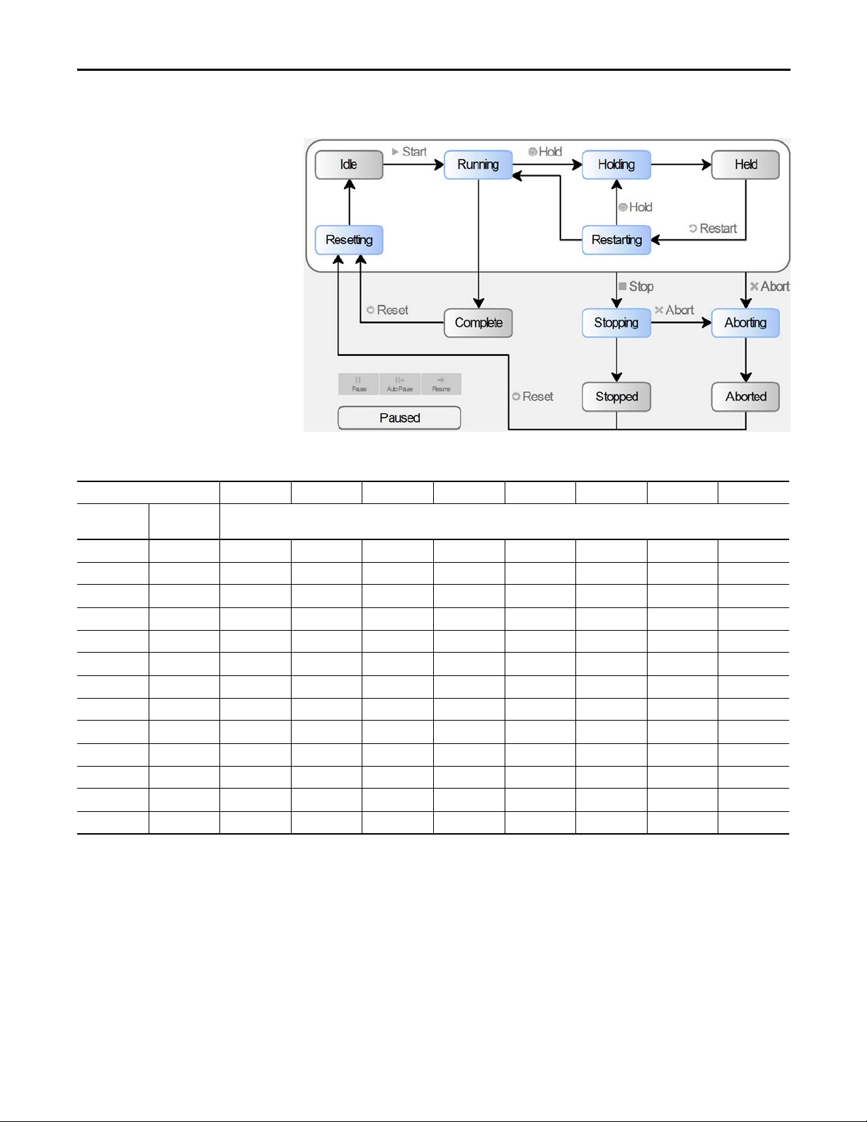
Structure Logic According to Standards Chapter 6
State Model
A state model helps program the equipment in a structured way, which results in
the same behavior in all equipment throughout the plant.
Command Start Stop Hold Restart Abort Reset Pause Resume
Initial State No Command
State
Idle Running Stopping Aborting
Running Complete Stopping Holding Aborting Pausing
Complete Idle
Pausing Paused Stopping Holding Abor ting
Paused Stopping Holding Aborting Running
Holding Held Stopping Restarting Aborting
Held Stopping Holding Aborting
Restarting Running Stopping Holding Aborting
Stopping Stopped Aborting
Stopped Aborting Idle
Aborting Aborted
Aborted Idle
Resetting Idle Stopping Aborting
State Transition Matrix
Rockwell Automation Publication 1756-RM094K-EN-P - October 2020 69

Chapter 6 Structure Logic According to Standards
Notes:
70 Rockwell Automation Publication 1756-RM094K-EN-P - October 2020

Chapter 7
Produced and Consumed Data
The controllers support the ability to produce (broadcast) and consume
(receive) system-shared tags.
For two controllers to share produced or consumed tags, both controllers must
be in the same backplane or attached to the same control network. You cannot
bridge produced and consumed tags over two networks.
IMPORTANTIMPORTANT The actual number of produced and consumed tags that you can configure
over ControlNet® or EtherNet/IP™ in a project depends on the connection
limits of the communication module through which you produce or consume
the tags.
For more information on produced and consumed tags, see the Logix 5000
Controllers Produced and Consumed Tags Programming Manual, publication
1756-PM011
.
Rockwell Automation Publication 1756-RM094K-EN-P - October 2020 71

Chapter 7 Produced and Consumed Data
Guidelines for Produced and Consumed Tags
Guideline Description
You cannot bridge produced and consumed tags over
different networks.
Create the tag at controller scope. You can only produce and consume (share) controller-scoped tags.
Limit the size of the tag
to 500 bytes.
Combine data that goes to the same controller. If you are producing several tags for the same controller:
The following atomic data types can be directly produced
or consumed:
DINT
UDINT
LINT
ULINT
REAL
LREAL
Data structures can be produced or consumed Data structures include user-defined data types (UDT), strings, add-on-defined, predefined, and module-defined
AXIS_CIP_DRIVE Use AXIS_CIP_DRIVE to produce and consume axis data.
The data type in the producer and the consumer must
match.
Produce tags that are based on user-defined structures to
non-Logix devices.
Use a programmatic handshake to help ensure data is
exchanged.
Use a CPS instruction to buffer produced and consumed
data.
Use unicast EtherNet/IP communication to reduce
broadcast network traffic.
Monitoring produced and consumed data. Group produced and consumed tags as members in user-defined structures whose first member is a
Firmware revisions When adding the Producer controller to the I/O configuration list of the Consumer controller, the firmware revision
For two controllers to share produced or consumed tags, both controllers must be attached to the same network. You
can produce and consume tags over ControlNet or EtherNet/IP networks.
If you produce or consume a tag over a network, the tag must be ≤ 480 bytes. Network transfers require 20 bytes of
data overhead.
• Group the data into one or more user-defined structures. This uses fewer connections than producing each
tag separately.
• Group the data according to similar update intervals. To conserve network bandwidth, use a greater RPI for
less critical data.
The listed atomic data types can be produced or consumed individually or in arrays. Other atomic data types
(BOOL,SINT,USINT,INT,UINT) cannot be done individually or in arrays and are required to be part of a data structure to
be produced or consumed.
data structures. Data structures meeting the size requirements can be produced or consumed.
The data type for a produced or consumed tag must be the same in both the producer and the consumer.
The controller produces tags in 32-bit words. For devices that communicate in other word boundaries, such as 16-bit
words, the resulting data in the target device can be misaligned. To help avoid misalignment, structure the produced
data in a user-defined structure.
Produced tags continually transmit based on the RPI, so i t can be difficult to know when new data arri ves. You can set
a bit or increment a counter that is embedded in the produced tag to identify to the consumer that new data is
present. You can also provide a return handshake via a reverse produced/consumed tag, so that the original producer
knows that the consumer received and processed the tag.
Use the CPS instruction to copy the data to the outgoing tag on the producer side. Then use another CPS instruction to
copy the data into a buffer tag on t he consumer side.
The CPS instructions provide data integrity for data structures greater than 32 bits.
Important: The controller inhibits all interrupts while it executes a CPS instruction.
To reduce bandwidth use and preserve network integrity, some facilities block multicast Ethernet packets. You can
configure a produced and consumed tag to use multicast or unicast connections. Unicast connections help with the
following:
• Reduce network bandwidth
• Simplify Ethernet switch configuration
CONNECTION_STATUS type. This technique helps monitor connection status between controllers without increasing
execution time, such as using a GSV instruction to detect status.
does not have to match. However, the rack size and slot number must be correct.
72 Rockwell Automation Publication 1756-RM094K-EN-P - October 2020

Guidelines for Produced and Consumed Axis
Guideline Description
You can configure a produced and consumed axis
between controllers in a chassis or over an EtherNet/IP
network.
Use a produced and consumed axis to synchronize motion
functions across multiple controllers.
Controllers that support motion support the AXIS_CIP_DRIVE data type for produced and consumed tags.
Synchronize functions such as:
•PCAM
•GEAR
• MDSC moves
• Scheduled outputs
• Registration events
• Position-based interlocks (handshake)
Produced and Consumed Data Chapter 7
Guidelines to Specify an RPI
Rate for Produced and
When configuring produced and consumed tags, you specify a requested
packet interval (RPI) rate. The RPI value is the rate at which the controller
attempts to communicate with the module.
Consumed Tags
Guideline Description
Make sure that the RPI is equal to or greater than the NUT. You use RSNetWorx™ for ControlNet software to select the network update time (NUT) and the software schedules
RPI of multicast tags • For Studio 5000 Logix Designer® application version 24 and earlier: The smallest (fastest) consumer RPI
the network connections.
RSNetWorx software cannot schedule a ControlNet network if a module and/or produced/consumed tag on the
network has an RPI that is faster than the network update time.
determines the RPI for the produced tag. If multiple consumers request the same tag, the smallest (fastest)
request determines the rate at which the tag is produced for all consumers.
• For Studio 5000 Logix Designer application version 28 and later: the first consumer of a produce tag determines
the RPI at which data is produced. All subsequent consumers must request the same RPI value as the first
consumer. Otherwise, the subsequent consumers fail to connect.
Guidelines to Manage Connections for Produced and Consumed Tags
Guideline Description
Minimize the use of produced and consumed tags. To reduce network traffic, minimize the size of produced and consumed tags. Also, minimize the use of produced and
Use arrays or user-defined structures. When sending multiple tags to the same controller, use an array or user-defined structure to consolidate the data. The
Configure the number of consumers accurately. Make sure the number of consumers that are configured for a produced tag is the actual number of controllers that
Multiple produced/consumed connections are linked. If there are multiple produced and consumed connections between two controllers and one connection fails, all
consumed tags to high-speed, deterministic data, such as interlocks.
byte limit of 500 bytes per produced and consumed tag still applies.
consumes the tag. If you set the number higher than the actual number of controllers, you unnecessarily use up
connections.
The default is two consumers per produced tag.
produced and consumed connections fail.
Consider combining all produced and consumed data into one structure or array so that you only need one connection
between the controllers.
Rockwell Automation Publication 1756-RM094K-EN-P - October 2020 73

Chapter 7 Produced and Consumed Data
Configure an Event Task Based on a Consumed Tag
An event task executes automatically based on a preconfigured event occurring.
One such event can be the arrival of a consumed tag.
• Only one consumed tag can trigger a specific event task.
• Use an IOT instruction in the producing controller to signal the
production of new data.
• When a consumed tag triggers an event task, the event task waits for all
data to arrive before the event task executes.
Compare Messages and Produced/Consumed Tags
Method Benefits Considerations
Read/Write Message • Programmatically initiated
• Communication and network resources that are only used when
needed
• Support automatic fragmentation and reassembly of large data
packets, up to as many as 32,767 elements
• Some connections can be cached to improve retransmission time
• Generic CIP™ message useful for third-party devices
Produced/Consumed Tag • Configured once and sent automatically based on requested
packet interval (RPI)
• Multiple consumers can simultaneously receive the same data
from a produced tag
• Can trigger an event task when consumed data arrives
• ControlNet resources are reserved up front
• Does not affect the scan of the controller
• Delay can occur if resources are not available when needed
• MSG instruction and processing can impact controller scan
(system overhead timeslice)
• Data arrives asynchronous to program scan (use a programmatic
handshake or a UID/UIE instruction pair to reduce impact, no
event task support)
• Can add additional messages online in Run mode.
• Support limited to Logix 5000™ and PLC-5® controllers, and the
1784-KTCS I/O Linx and select third-party devices
• Limited to 500 bytes over the backplane and 480 bytes over a
network
• Must be scheduled when using ControlNet
• Data arrives asynchronous to program scan (use a programmatic
handshake or CPS instruction and event tasks to synchronize)
• Connection status must be obtained separately
• You can configure status information for a produced/consumed
tag
• On an EtherNet/IP network, you can configure produced/
consumed tags to use multicast or unicast connections.
• Cannot create additional produced/consumed tags online in Run
mode.
74 Rockwell Automation Publication 1756-RM094K-EN-P - October 2020

Chapter 8
Data Structures
The controllers support IEC 61131-3 atomic data types, and compound data
types, such as arrays, predefined structures (such as counters and timers), and
user-defined structures.
Guidelines for Data Types
Guideline Description
Use DINT data types whenever possible The controllers per form DINT (32 bit) and REAL (32 bit) math operations. DINT data types use less memory and execute
Group BOOL values into arrays When you use BOOL values, group them into DINT arrays to best use controller memory and to make the bits accessible
Memory SINT INT DINT REAL
Memory that is reserved for a standalone tag 4 bytes 4 bytes 4 bytes 4 bytes
Memory that is reserved for data in a user-defined structure 1 byte
Memory that is used to access a tag in an ADD instruction 236 bytes 260 bytes 28 bytes 44 bytes
Follow these guidelines depending on the data type for your application.
faster than other data types. Use the following data type:
• DINT for most numeric values and array indexes.
• REAL for manipulating floating point, analog values.
• SINT (8 bit) and INT (16 bit) primarily in user-defined structures or when communicating with an external device that
does not support DINT values.
via FBC or DDT instructions.
(8-bit aligned)
2 bytes
(16-bit aligned)
4 bytes
(32-bit aligned)
4 bytes
(32-bit aligned)
A tag uses additional memory in the controller to store the tag name and
symbol, and allocate memory for data.
To manipulate SINT or INT data, the controller converts the values to DINT
values, performs the programmed manipulation, and then returns the result to
a SINT or INT value. This requires additional memory and execution time
when compared to using DINT values for the same operation.
Rockwell Automation Publication 1756-RM094K-EN-P - October 2020 75

Chapter 8 Data Structures
BOOL[96] = 12 bytes
BOOL arrays use 32-bit
increments of memory
SINT[10] = 12 bytes of memory (2 bytes unused)
INT[5] = 12 bytes of memory (2 bytes unused)
DINT[3] = 12 bytes and REAL[3] = 12 bytes
SINT arrays are padded to use
any left over bytes
INT arrays are padded to use
any left over bytes
DINT and REAL arrays use
4-byte increments of memory
Arrays
An array allocates a contiguous block of memory to store a specific data type as
a table of values.
• Tags support arrays in one, two, or three dimensions.
• User-defined structures can contain a single-dimension array as a
member of the structure.
This array Stores Data like For Example
One dimension Tag name
one_d_array
Total number of elements = 7
Valid subscript range DINT[a] where a=0…6
Two dimension Tag name
two_d_array
Total number of elements = 4 5 = 20
Valid subscript range DINT[a,b] where a=0…3; b=0…4
Three dimension Tag name
three_d_array
Total number of elements = 2 3 4 = 24
Valid subscript range DINT[a,b,c] where a=0…1; b=0…2, c=0…3
Typ e
DINT[7]
Typ e
DINT[4,5]
Typ e
DINT[2,3,4]
Dimension 0
7
Dimension 0
4
Dimension 0
2
Dimension 1
—
Dimension 1
5
Dimension 1
3
Dimension 2
—
Dimension 2
—
Dimension 2
4
The data type you select for an array determines how the contiguous block of
memory gets used.
76 Rockwell Automation Publication 1756-RM094K-EN-P - October 2020

Data Structures Chapter 8
Guidelines for Arrays
Guideline Description
You can create arrays of most data types, except for
ALARM_xxx, AXIS_xxx, COORDINATE_SYSTEM,
ENERGY_xxx, HMIBC, MESSAGE, and MOTION_GROUP
data types.
Type of Array Benefit Considerations
Single (1) dimension • Better support by native file instructions
Double (2) dimension
and
Triple (3) dimension
Nest arrays. The file instructions offer limited support for arrays. To work with array data, create a user-defined structure with one
Select the data type of the array based on the data
and the instructions that manipulate that data.
Limit arrays to 2 MB of data. The maximum array size is 2 MB. The software displays a warning if you try to create an array that is too large. The
Edit arrays online and offline. You can create arrays when online or offline. However, you can modify only the size or data type of an existing array when
A subscript identifies an individual element within the array. A subscript starts at 0 and extends to the number of
elements minus 1 (zero based).
• Single-dimension arrays take less memory and execute faster than two-dimension or three-dimension arrays.
• Direct references to array elements execute faster than indexed references.
• An array can be as large as 2 MB.
• If you create an array of structures, the memory for each element is allocated based on the structure definition.
• Fully supported in user-defined structures and arrays
• Smallest impact (execution time and memory) for
indexed references
• Can create arrays when programming online
• Can provide a more accurate data representation for a
physical system
• Can emulate PLC file/word indirection with a twodimension array
• Can create arrays when programming online
array as a member of the structure. Then create an array tag by using the user-defined structure as its data type.
While SINT and INT arrays can compact more values into a given memor y area, they require additional memory and
execution time for each instruction that references the array.
software also displays a warning if an array is 1.5…2 MB, even though these sizes are valid.
offline.
• Multi ple arrays cannot be indirectly referenced like in
PLC or SLC™ processors (such as, N[N7:0]:5)
• BOOL arrays are not directly supported by file
instructions
• Can be changed only when programming offline
• Larger impact (execution time and memory) for
indexed references
• File manipulation requires extra code and file
instructions
• Can only be changed when programming offline
Indirect Addresses of Arrays
If you want an instruction to access different elements in an array, use a tag in
the subscript of the array (an indirect address). By changing the value of the
tag, you change the element of the array that your logic references.
When index equals 1, array[index] points here.
array[0] 4500
array[1] 6000
array[2] 3000
array[3] 2500
When index equals 2, array[index] points here.
When you directly reference an element in an array (such as MyArray[20]),
uses less memory and executes faster than an indirect reference
(MyArray[MyIndex]). You can also indirectly address bits in a tag
(MyDint.[Index]).
If you use indirect addresses, use DINT tags because other data types require
conversion and execute slower. For each indexed access to data, the controller
recalculates the array index. If you access a specific array element multiple
times, copy the data out of the array into a fixed tag and use that tag in
subsequent logic.
Rockwell Automation Publication 1756-RM094K-EN-P - October 2020 77

Chapter 8 Data Structures
Operator Description Optimal
+ Add DINT, REAL
- Subtract/negate DINT, REAL
* Multiply DINT, REAL
/Divide DINT, REAL
** Exponent (x to y) DINT, REAL
ABS Absolute value DINT, REAL
ACS Arc cosine REAL
AND Bit wise AND DINT
ASN Arc sine REAL
ATN Ar c t ang en t R EAL
COS Cos ine REAL
DEG Radians to degrees DINT, REAL
FRD BCD to integer DINT
LN Natural log REAL
LOG L og ba se 10 RE AL
MOD Modulo divide DINT, REAL
NOT Bitwise complement DINT
OR Bitwise OR DINT
RAD Degrees to radians DINT, REAL
SIN Sine REAL
SQR Square root DINT, REAL
TAN Ta nge nt R EA L
TOD Integer to BCD DINT
TRN Truncate DINT, REAL
XOR Bitwise exclusive OR DINT
Operator Description Optimal
You can also use an expression to specify the index value. For example:
MyArray[10 + MyIndex].
• An expression uses operators to calculate a value.
• The controller computes the result of the expression and uses it as the
index.
• These are valid operators.
Guidelines for Array Indexes
Guideline Description
Use the SIZE instruction to determine the number of
elements in an array.
Use immediate values to reference array elements. Immediate value references to array elements are quicker to process and execute faster than indexed references.
Use DINT tags for array indexes. DINT tags execute the fastest. SINT, INT, and REAL tags require conversion code that can add additional scan time to an
Avoid using array elements as indexes. The controller does not directly support the use of an array element as the index to look up a value in another array. To
78 Rockwell Automation Publication 1756-RM094K-EN-P - October 2020
By determining the number of elements in an array at runtime, you can write reusable code that adjusts itself to meet
each instance where it is used.
The SIZE instruction returns the number of elements. Arrays are zero-based, so subtract 1 from the result to determine
the last element position.
operation.
work around this, you can create an alias to the element and then use this as the index. Or copy the element to a base tag
and use that base tag as the index.

Data Structures Chapter 8
Guidelines for User-defined Data Types (UDT)
Guideline Description
Group members of the same data type within a structure. You can create members of most data types, except for AXIS, COORDINATE_SYSTEM, MOTION_GROUP, and MESSAGE
Arrays within a UDT can only be 1-dimension. If you include an array as a member, limit the array to one dimension. Multidimension arrays are not permitted in a
I/O data that is used in a UDT must be copied into the
members.
Limit user-defined data types to 500 members. The controllers limit user-defined struc tures to 500 members. If you need more, consider nesting structures within the
Limit user-defined data types to 2 MB of data. The maximum UDT size is 2 MB. The software displays a warning if you try to create an UDT that is too large. The
Limit the size of user-defined structures if they are to be
produced and consumed tags.
Use the appropriate instruction to load data into a
structure.
Use structure descriptions to automatically create tag
descriptions.
Online and offline editing. You can create user-defined structures when online or offline. However, you can modify only an existing structure
data types.
Place members that use the same data type in sequence.
The controller aligns every data type along an 8-bit boundary for SINTs, a 16-bit boundary for INTS, or a 32-bit
boundary for DINTs and REALs. BOOLs also align on 8-bit boundaries, but if they are placed next to each other in a
user-defined structure, they are mapped so that they share the same byte.
user-defined structure.
If you include members that represent I/O devices, you must use logic to copy the data into the members of the
structure from the corresponding I/O tags.
Make sure that the data type of the struc ture member matches the I/O data type to avoid data type conversion.
main structure.
software also displays a warning if the UDT is 1.5…2 MB, even though these sizes are valid.
Produced and consumed tags are limited to 500 bytes over the backplane and 480 bytes if over a network.
Linx-based software can optimize user-defined structures that are less than 480 bytes. UDT larger than the noted
produced and consumed tag limits must use a MESSAGE instruction (MSG) if they are to be communicated.
Load input values into the user-defined structure at the beginning of the program and copy output values from the
user-defined structure at the end of the program.
• Single bit - Examine On (XIC) and Output Energize (OTE) instructions
• Contiguous bits - Bit Field Distribute (BTD) instruction
• Single value - MOV instruction
• Multiple contiguous values -COP/CPS instruction
Enable the Use Pass-through Description workstation option (Tools > Options > Display) to display the descriptions
you add to the members of structures for each tag that uses that structure data type.
when offline.
Rockwell Automation Publication 1756-RM094K-EN-P - October 2020 79

Chapter 8 Data Structures
MyBit:BOOL
BitTable:BOOL[32]
FaultTable:DINT[3]
BitStructure
Bit1:BOOL
Bit2:BOOL
Select a Data Type for Bit Tags
Bits in a controller can exist as: BOOL tags, bits in a BOOL array, bits in
elements of a SIN T, USI N T, I N T, U INT, DI N T, UD IN T, LIN T, UL I NT
array, members of a user-defined structure, or as bits in a SINT, USINT, INT,
UINT, DINT, UDINT, LINT, ULINT member of a user-defined structure.
Tag Type Description
BOOL tag Each tag accesses a specific bit. Each tag uses 4 bytes.
Benefits Considerations
• Each bit has a specific tag • Requires extra bandwidth to communication
BOOL array A BOOL array combines multiple bits into adjacent words (32-bit words).
Benefits Considerations
• Consolidates multiple bits into one word
• Better use of memory
• Can address all bits in an array by using indirect
addressing
DINT array A DINT combines multiple bits into adjacent words.
Benefits Considerations
• Consolidates multiple bits into one word
• File instructions, copy instructions, and DDT/FBC
instructions support DINT arrays
• Lets you access the bits by element (word) and
bit number
• Uses more memory
• Cannot use FBC/DDT bit file instructions
• BOOL data type only supported by bit instructions
• Cannot use file instructions, copy instructions, or DDT/
FBC instructio ns
• Requires extra planning to indirectly address bits
• Difficult to address bits in the array by using indirect
addressing
User-defined structure A user-defined structure combines multiple bits into adjacent, individually named words.
Benefits Considerations
• Object based
• Consolidates multiple bits into one word
• Third-party MMI/EOI products do not directly support
structures.
• Cannot use FBC/DDT bit file instructions
80 Rockwell Automation Publication 1756-RM094K-EN-P - October 2020

Data Structures Chapter 8
Serial Bit Addresses
The BOOL B data table in the PLC-5® and SLC™ 500 processors supports two
address modes that can address the same bit.
Address Mode Description
Serial bit
In PLC-5 or SLC software, this addressing mode is
represented as /Bit
Word bit
In PLC-5 or SLC software, this addressing mode is
represented as Word/Bit
Serial bit addressing references all bits as a contiguous list (array) of bits. For example, if you want to reference the third
bit in the second word of a B file, specify B3/18. This method is similar to a BOOL array in a Logix 5000™ controller
where you specify FaultBit[18].
Word bit addressing identifies a bit within a specific word. For example, B3:1/2 is the s ame as B3/18 from the serial bit
example. This method is similar to accessing the bits of a SINT, INT, DINT array in a Logix 5000 controller where you
specify FaultTable[1].2.
The Logix 5000 controller supports both of these addressing modes, but you
cannot use both to reference bits in the same array due to conformance with
the IEC 61131-3 standard. Choose the method that best meets your
application needs. You can copy data between arrays by using both methods.
You can also use an expression to indirectly reference a bit in a DINT array by
using a serialized bit number. For example:
Ta g
MyBits : DINT[10]
BitRef : DINT
EndTag
MOV(34, BitRef )
XIC(MyBits[BitRef / 32].[BitRef AND 31])
where:
This expression Calculates the
[BitRef / 32] Element in the DINT array
If the tag MyBits is an INT or SINT, the divisor is 16 or 8, respectively.
[BitRef AND 31] Bit within the element
If the tag MyBits is an INT or SINT, the mask value is 15 or 7, respectively.
The Diagnostic Detect (DDT) and File Bit Compare (FBC) instructions
provide a bit number as a result of their operation. These instructions are
limited to DINT arrays so you can use them to locate the bit number that is
returned from the example above.
Rockwell Automation Publication 1756-RM094K-EN-P - October 2020 81

Chapter 8 Data Structures
Guidelines for String Data Types
Guideline Description
You can create a string data type that is longer or
shorter than the default string data type.
Only some instructions support string data types. These comparison instructions suppor t string tags: EQU, NEQ, GRT, GEG, LES, LEQ, C MP.
Use the SIZE instruction to determine the number of
characters in a string.
Use the DTOS, RTOS, and CONCAT instructions to embed
tag values within a string.
Set the LEN fie ld to indicate the number characters that
are present.
String data types are structures that hold ASCII characters. The first member
of the structure defines the length of the string; the second member is an array
that holds the actual ASCII characters.
The default string data type can contain as many as 82 characters. You can create custom-length string data types that
range from 1 to 65535 characters.
These serial port instructions support string tags: ARD, ARL, AWA, AWT.
These string-handling instructions support string tags: STOD, DTOS, STOR, RTOS, CONCAT, MID, FIND, DELETE, INSERT,
UPPER, LOWER, SIZE.
These file instructions support string arrays: FAL, FFL, FFU, LFL, LFU, COP, CPS, FSC.
By determining the number of characters in a string at runtime, you can write reusable code that adjusts itself to meet
each instance where it is used.
The SLC 500 processor supports the ability to embed a data-table reference address within a string (inline indirection).
The SLC 500 AWA and AWT instructions can then look up the data value and place an ASCII representation into the
outgoing string. The Logix 5000 controller does not directly support this ability. Use the DTOS or RTOS instructions to
convert a value to a string and the CONCAT instruction to merge characters with another string.
The LEN field in the string structure indicates how many characters are in the string. The programming software and the
controller instructions that manipulate strings use the LEN value to determine how many positions in the string DATA
array contain valid characters. Both the programming software and the instructions stop processing the DATA array once
they reach the LEN value.
PLC-5/SLC 500 Access of Strings
The ASCII A data table in the PLC-5 and SLC 500 processors uses a string
format that is similar to the Logix string data type. The main difference is that
the LEN field (length) in a PLC-5/SLC 500 processor is a 16-bit, INT value.
The LEN field in a Logix 5000 controller is a 32-bit, DINT field. This
difference can impact converted logic and data communication. The Logix
5000 controller converts the LEN field to the appropriate value and size when
a PLC-5/SLC 500 message format is used to read or write a string.
82 Rockwell Automation Publication 1756-RM094K-EN-P - October 2020
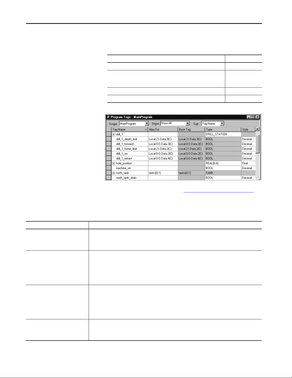
Data Structures Chapter 8
Configure Tags
A tag is a text-based name for an area of controller memory where data is
stored. Tags are the basic mechanism to allocate memory, reference data from
logic, and monitor data.
If you want the tag to Then choose this type
Store a value for use by logic within the project Base
Use another name for an existing tag’s data
(can help simplify long, pre-determined tag names, such as for I/O dat a or user-defin ed
structures)
Send (broadcast) data to another controller Produced
Receive data from another controller Consumed
Alias
For more information on I/O tags, see Communicate with I/O on page 89
Guidelines for Base Tags
Guideline Description
Create standalone atomic tags. The controller supports pre-defined, standalone tags.
Create user-defined structures User-defined struc tures (data types) let you organize your data to match your machine or process.
Use arrays like files to create a group of
similar tags.
Take advantage of program-scoped tags. If you want multiple tags with the same name, define each tag at the program scope (program tags) for a different program. This
• Atomic tags are listed directly in the Tag Editor and Data Monitor and can easily be found by browsing the alphabetical list.
• Atomic tags can be created online, but the data type can be only modified offline.
Using only atomic tags can impact HMI communication performance as more information must be passed and acted on.
• One tag contains all data that is related to a specif ic aspect of your system. This keeps related data together and easy to locate,
• Each piece of data (member) gets a descriptive name.
• You can use the structure to create multiple tags with the same data layout.
• User-defined structure can only be modified offline.
Linx-based software optimizes user-defined structures more than standalone tags.
An array creates multiple instances of a data type under a common tag name.
• Arrays let you organize a block of tags that use the same data type and perform a similar function.
• You organize the data in one, two, or three dimensions to match what the data represents.
• Arrays can be only modified offline.
• Linx-based software optimizes array data types more than standalone tags.
Minimize the use of BOOL arrays. Many array instructions do not operate on BOOL arrays, making it more difficult to initialize and
clear an array of BOOL data.
lets you reuse both logic and tag names in multiple programs.
Avoid using the same name for both a controller tag and a program tag. Within a program, you cannot reference a controller tag if
a tag of the same name exists as a program tag for that program.
Use the following guidelines for base tags.
regardless of its data type.
.
Rockwell Automation Publication 1756-RM094K-EN-P - October 2020 83

Chapter 8 Data Structures
Guideline Description
Use mixed case and the underscore
characters.
Consider alphabetical order. The programming software displays tags of the same scope in alphabetical order. To make it easier to monitor related tags, use
Use leading zeroes (0) when numbers are
part of tag names
Although tags are not case-sensitive (upper case A is the same as lower case a), mixed case is easier to read. For example, Tank_1
can be easier to read than tank1.
similar starting characters for tags that you want to keep together. For example, consider using Tank_North and Tank_South
rather than North_Tank and South_Tank.
The programming software uses a simple sort to alphabetize tag names in the Ta g Editor and Data Monitor. This means if you have
Tag1, Tag2, Tag11, and Tag12, the software displays them in order as Tag1, Tag11, Tag12, and then Tag2. If you want to keep them
in numerical order, name them Tag01, Tag02, Tag11, and Tag12.
Create Alias Tags
An alias tag lets you create one tag that represents another tag.
• Both tags share the same value as defined by the base tag.
• When the value of a base tag changes, all references (aliases) to the base
tag reflect the change.
Guideline Description
Upload behavior for al ias tags. For 5370 and 5570 controllers, there are situations when uploading a project file that instruction operands that use alias references
Alias tags do not affect controller execution. During download, the program is compiled into machine executable code and physical memory addresses. While the existence of
Access alias tags from Linx-based software. Because an alias tag appears as a standalone tag to Linx-based software, an alias tag that ref erences a comp ound array or structure
can change. To avoid these situations with ladder instruction operands, do not use:
• Nested aliases (also known as an alias chain)
• Multiple aliases to the same tag
On an upload, the software uses a technique referred to as “best fit” to reconstruct instruction operands and operands that use an
alias can change.
This does not apply to 5380, 5480 and 5580 controllers and on an upload, the aliases for these controllers are faithfully reproduced.
an alias requires controller memory to store the name, the program performs the same operation for a reference with an alias or its
associated base tag.
can require additional communication time. When you reference tags from Linx-based software or other HMI, it can be fastest to
reference base tags dire ctly.
84 Rockwell Automation Publication 1756-RM094K-EN-P - October 2020

Data Structures Chapter 8
Control ler
scope
Program
scope
Phase
scope
Guidelines for Data Scope
Data scope defines where you can access tags. Controller-scoped tags and
parameters are accessible by all programs. Local tags are accessible only by the
code within a specific program. Equipment Phases, like Programs, have
parameters and local tags.
If you want to Then assign this scope
Produce or consume data Controller scope (controller tags)
Use a tag in multiple programs in the same project Controller scope (controller tags)
Use a tag in a message (MSG) instruction
Use motion tags
Reuse the same tag name multiple times for different parts or processes
within a controller
Have multiple programmers work on logic and you want to merge logic into
one project
Param eters
Param eters
Local Tags
Isolate portions of a machine or different stations into separate programs or
equipment phases and use program-scoped or phase-scoped tags. This lets you
do the following:
• Provide isolation between programs and equipment phases
• Help prevent tag name collisions
• Improve the ability to reuse code
See publication 1756-PM021, Logix 5000 Controllers Program Parameters
Programming Manual, for more information on Parameters.
Guidelines for Tag Names
Guideline Description
Create descriptive names but keep them short. Tag names can be from 140 charac ters long.
Create a naming convention. Develop a tag-naming convention on electrical drawings or machine design. For example, Conv1_Full_PE101 combines the
Use correct characters in tag names. Tag names follow the IEC 61131-3 standard. You can use:
Pad names to improve sort order. The programming software displays tags in alphabetical order. If you use numbers in your tag names, pad the number with
Use the following guidelines when you name tags.
• Each character of the tag name uses 1 byte of controller memor y, rounded to a 4-byte boundar y.
• For example, a tag name with 1…4 characters uses 4 bytes. A tag name with 5 characters uses 8 bytes.
• Tag names are stored in the controller.
• Use structures to reduce the number and size of tags needed.
Program upload preserves tag names.
sensor function with the photoeye number.
• Letters A through Z.
•Numbers 0…9.
• Underscore character (_).
Tags must start with a letter to avoid confusion with logical expressions. The remaining characters can be any of the supported
characters.
leading zeros so the names sort in the proper order.
For example, tag names: TS1, TS2, TS3, TS10, TS15, TS20, TS30 display as: TS1, TS10, TS15, TS2, TS20,TS3, and TS30.
Pad the numbers with zero so they display as: TS01, TS02, TS03, TS10, TS15, TS20, TS30.
Rockwell Automation Publication 1756-RM094K-EN-P - October 2020 85

Chapter 8 Data Structures
Type of Tag Description Display in the programming software
Atomic For a BOOL, SINT, USINT, INT, UINT, DINT, UDINT, LINT, ULINT, REAL or LREAL tag, the description that is
associated with the tag is the only description available for display.
Alias First the alias tag description, then the base tag description.
User-defined
structure and
Add-On
Instruction
All members use the description for tag, unless you define a specific description for a member.
For example, MyTimer.DN uses the description for MyTimer if there is no description for MyTimer.DN.
Atomic array • All references into an array use the description for the array, unless you define a description for an
element of the array.
• For example, MyTable[10] uses the description for MyTable if there is no description for MyTable[10].
• All indexed references into an array use the description for the array.
• For example, MyTable[Index] uses the description for MyTable.
Structure array All references to a member of a structure in an array default to the array definition, unless you define a
description for the structure member of the array.
For example, Table[0].Field1 uses the description for Table if there is no description for the specific field.
Guidelines for Extended Tag
Use the following guidelines for extended tag properties.
Properties
Guideline Description
Use extended tag properties to define additional
information, such as limits, engineering units, or
state identifiers, for various components within
your controller project.
Some extended tag properties support passthrough for data structures and arrays.
You can read extended properties via logic, but you
cannot write to extended properties values in logic.
If an array tag uses indirect addressing to access
limit extended properties in logic, the following
conditions apply.
You can define extended tag properties for these components:
•Tag
• Parameter
• User-defined data type
• Add-On Instruction
Pass-through behavior is available for descriptions, state identifiers, and engineering units and is configurable in data
structures and arrays.
Pass-through behavior is not available for limits.
• Extended properties must be used as an input operand.
• Alias tags with extended properties cannot be accessed in logic.
• Limits can be configured for input and output parameters in Add-On Instructions. However, limit extended properties
must not be defined on an InOut parameter of an Add-On Instruction.
• Limits cannot be accessed inside Add-On Instruction logic.
• If you read an extended property value in logic, it consumes memor y equival ent to an equ ivalent prog ram-scoped tag of
that data type. If you do not use them in logic, extended tag properties use no user memory, only extended memory.
• If the array tag has limit extended properties that are configured, the extended properties are applied to any array
element that does not explicitly have that particular extended property configured. For example, if the array tag
MyArray has Max configured to 100, then any element of the array that does not have Max configured inherits the value
of 100 when used in logic. However, it is not visible to you that the value inherited from MyArray is configured in the tag
properties.
• At least one array element must have specific limit extended property configured for indirectly referenced array logic to
verify. For example, if MyArray[x].@Max is being used in logic, at least one array element of MyArray[] must have Max
extended property configured if Max is not configured by MyArray.
• Under the following circumstances a data type default value is used:
– Array is accessed programmatically with an indirect reference.
– Array tag does not have the extended property configured.
– A member of an array does not have the extended property configured.
Tag Descriptions
The programming software searches a tag’s origin to locate the first available
description. This reduces the number of descriptions you need to enter. This
also verifies that tag references display associated descriptions.
Guideline Description
Tag descriptions display in the programming
software according to the tag’s origin.
86 Rockwell Automation Publication 1756-RM094K-EN-P - October 2020
For more information, see the Create Tag Descriptions Automatically with
User-Defined Data Types White Paper, publication LOGIX-WP004
.

Data Structures Chapter 8
Protect Data Access Control
New tag attributes define access to tag data at runtime.
at Tag Level
Tag Attribute Description
External access Defines how an external application, such as an HMI, historian, or OPC data server, can access a tag. For arrays, this
Constant Defines whether a tag value remains constant. Tags with this attribute set cannot be changed programmatically.
feature applies to the top level only; for user- defined structure, this feature applies to individual members. Possible
values are:
• Read/Write: External applications can both read and modify the tag’s value
• Read Only: External applications can read the tag’s value, but not modify it
• None: External applications can neither read or write the tag’s value
You can Use RSLinx® Classic software, version 2.56 or later, RSLinx Enterprise
software, versions 5.21 to 5.90, or FactoryTalk® Linx software version 6.00 or
later, for best results with these tag attributes. Using earlier versions of RSLinx
software can result in anomalous behavior from the data servers with the
external access options of Read Only and None.
Rockwell Automation Publication 1756-RM094K-EN-P - October 2020 87

Chapter 8 Data Structures
Notes:
88 Rockwell Automation Publication 1756-RM094K-EN-P - October 2020

Chapter 9
Communicate with I/O
I/O values update at a period, requested packet interval (RPI), which you
configure via Module Property dialog in the I/O configuration folder of the
project. The values update asynchronously to the execution of logic.
The module sends input values to the controller at the specified RPI. Because
this transfer is asynchronous to the execution of logic, an I/O value in the
controller can change in the middle of a scan.
Buffer I/O Data
If you reference an I/O tag multiple times, and the application could be
impacted if the value changes during a program scan, you must buffer the I/O
value. You can buffer an I/O tag by using input parameters or coping into a
buffer tag. In your code, reference the buffer tag rather than the I/O tag.
IMPORTANT Use the synchronous copy (CPS) instruction to buffer I/O data. While the CPS
instruction copies data, no I/O updates or other tasks can change the data.
Tasks that attempt to interrupt a CPS instruction are delayed until the
instruction is done. Overuse of the CPS instruction can impact controller
performance by keeping all other tasks from executing.
Buffer I/O data to do the following:
• Help prevent an input or output value from changing during the
execution of a program (I/O updates asynchronous to the execution of
logic).
• Copy an input or output tag to a member of a structure or element of an
array.
• Help prevent produced or consumed data from changing during the
execution of a program.
• Make sure all produced and consumed data arrives or is sent as a group
(not mixed from multiple transfers).
• Only use the CPS instruction if the I/O data that you want to buffer is
greater than 32 bits (or 4 bytes) in size.
Overuse of the CPS instruction can greatly impact controller performance.
If you have a user-defined structure with members that represent I/O devices,
you must use logic to copy the data into the members of the structure from the
corresponding I/O tags.
Rockwell Automation Publication 1756-RM094K-EN-P - October 2020 89

Chapter 9 Communicate with I/O
Guidelines to Specify an RPI Rate for I/O Modules
Guideline Description
Specify an RPI at 50% of the rate you need new data. If you set the RPI faster (specify a smaller number) than what your application needs, it can waste network resources, such
Group devices with similar performance needs onto
the same module.
Set the ControlNet™ network update time (NUT)
equal to or less than the fastest RPI.
In an ControlNet system, use even multiples of the
NUT for the RPI value.
In a ControlNet system, isolate I/O communication. If you use unscheduled ControlNet communication or want to be able to add ControlNet I/O at runtime (see page 98
In an EtherNet/IP™ system, module change of state is
limited to 1/4 of the RPI.
Data transmission depends on the controller. The type of controller determines the data transmission rate.
Configure an RPI rate per module (ControlLogix®) or an RPI rate per
controller (CompactLogix™). The RPI value is the rate at which the controller
attempts to communicate with the module.
as ControlNet® schedule bandwidth, network processing time, and CPU processing time.
For example, if you need information every 80 ms, set the RPI at 40 ms. The data is asynchronous to the controller scan, so
you sample data twice as often (but no faster), you ensure that you have the most current data.
By grouping devices with similar performance needs on the same module, you consolidate data transmission to one
module rather than multiple modules. This conserves network bandwidth.
When configuring a ControlNet network, set the network update time (NUT) equal to or less than the fastest RPI of the I/O
modules and produced/consumed tags in the system. For example, if your fastest RPI is 10 ms, set the NUT to 5 ms for
more flexibility in scheduling t he network.
Set the RPI to a binary multiple of the NUT. For example, if the NUT is 10 ms, select an RPI such as 10, 20, 40, 80, or
160 ms.
),
dedicate one ControlNet network to I/O communication only. On the dedicated I/O network, make sure that there is
the following:
• No HMI traffic
• No MSG traffic
• No programming workstations
• No peer-to-peer interlocking in multi-processor system architectures
If you configure change of state communication for a module in a remote chassis that is connected via an EtherNet/IP
network, the module can send data only as fast as the module RPI. Initially, the module sends its data immediately.
However, when an input changes, the module data is held at the adapter until 1/4 of the RPI is reached to avoid
overloading the EtherNet/IP network with the module communication.
• ControlLogix controllers transmit data at the RPI you configure for the module.
• CompactLogix controllers transmit data at powers of 2 ms (such as 2, 4, 8, 16, 64, or 128). For example, if you specify an
RPI of 100 ms, the data actually transfers at 64 ms.
90 Rockwell Automation Publication 1756-RM094K-EN-P - October 2020
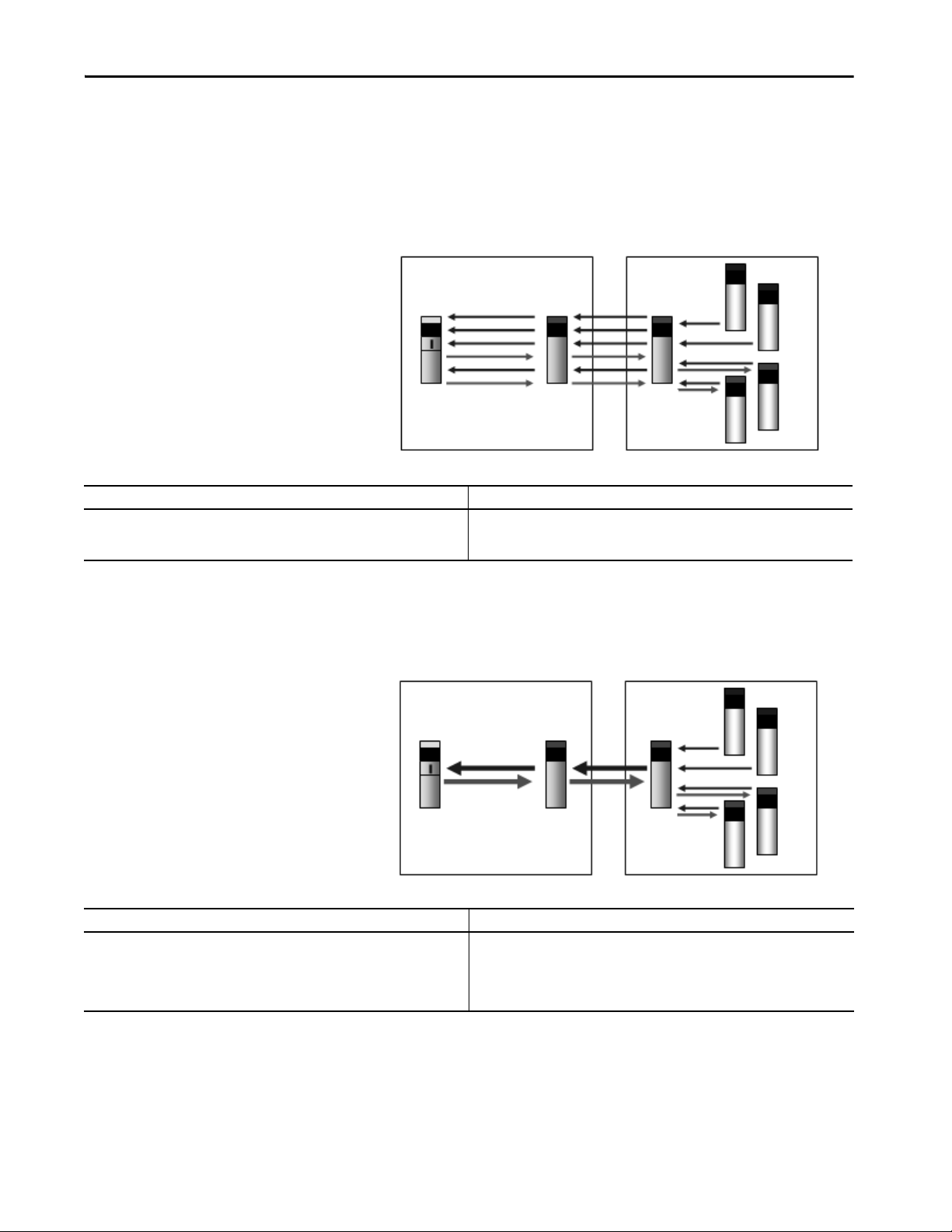
Communicate with I/O Chapter 9
Local Chassis Remote Chassis
Controlle r
Communication
Module
Communication
Module
Digital Inputs
Digital Outputs
Local Chassis Remote Chassis
Control ler
Communication
Module
Communication
Module
Digital Inputs
Digital Outputs
Communication Formats for I/O Modules
The communication format determines whether the controller connects to the
I/O module via a direct or a rack-optimized connection. The communication
format also determines the type and quantity of information that the module
provides or uses.
Direct Connection Each module passes its data to/from the controller individually.
Communication modules bridge data across networks.
Benefits Considerations
• Each module can determine its own rate (RPI)
• More data can be sent per module, such as diagnostic and analog data
• Supports event task communication
• Requires additional connections and network resources
• This is the only method that is supported in the local chassis
• I/O data is presented as individual tags
Rack-optimized Connection The communication module in a remote chassis consolidates data from
multiple modules into one packet and transmits that packet as one connection
to the controller.
.
Benefits Considerati ons
• One connection can service a full chassis of digital modules
• Reduces network resources and loading
The rack-optimized format limits data to one 32-bit input word per module in
a chassis. If you place a diagnostic module in a chassis, the rack-optimized
format eliminates the value that the diagnostic module offers. In this case, it’s
better to use a direct connection so that the diagnostic information from the
module is passed to the controller.
• All Modules are sent at the same rate
• Unused slots are still communicated
• Still need a direct connection for analog and diagnostic data
• Limited to remote chassis
• I/O data is presented as arrays with alias tags for each module
Rockwell Automation Publication 1756-RM094K-EN-P - October 2020 91

Chapter 9 Communicate with I/O
O
U
T
P
U
T
I
N
P
U
T
Output Echo
Connection / Peer Control
Output Data
Input Input
Connection Listen Only
Peer Control Output modules let peer ownership of input modules to consume input data to
directly control outputs without requiring controller processing.
The 1756-IB16IF and 1756-IB16IFC modules can be listened to presuming
the output module knows the input data layout and connection information.
The configuration from the controller defines how the peer input data is
mapped to the output modules. The controller can use the other digital points
on the module that are not peer-owned as conventional outputs.
The controller can also use the output data it normally sends to the module
with consumed inputs, letting ‘gate-type’ features enabled by controller logic
selectively letting application of the consumed peer input data.
.
Benefits Considerations
• Faster response time because the controller scan time is removed from the equation.
Data is sent directly to the output module from the input module.
• Increases controller performance by reducing the need for event tasks to close loops
quickly.
• Each input module has an AND an d OR bit mask that defines the logic that is applied to
each input module.
• You must program the controller for proper relationship with the output modules.
• The peer output module must be in the same chassis as the input module to
maximize response time.
92 Rockwell Automation Publication 1756-RM094K-EN-P - October 2020

Communicate with I/O Chapter 9
Electronic Keying
Electronic Keying reduces the possibility that you use the wrong device in a
control system. It compares the device that is defined in your project to the
installed device. If keying fails, a fault occurs. These attributes are compared.
Attribute Description
Vendor The device manufacturer.
Device Type The general type of the product, for example, digital I/O module.
Product Code The specific type of the product. The Product Code maps to a catalog number.
Major Revision A number that represents the functional capabilities of a device.
Minor Revision A number that represents behavior changes in the device.
The following Electronic Keying options are available.
Keying Option Description
Compatible
Module
Disable Keying Indicates that the keying attributes are not considered when attempting to communicate
Exact Match Indicates that all keying attributes must match to establish communication. If any attribute
Lets the installed device accept the key of the device that is defined in the project when the
installed device can emulate the defined device. With Compatible Module, you can typically
replace a device with another device that has the following characteristics:
• Same catalog number
• Same or higher Major Revision
• Minor Revision as follows:
– If the Major Revision is the same, the Minor Revision must be the same or higher.
– If the Major Revision is higher, the Minor Revision can be any number.
This is the default selection in the Logix Designer application.
with a device. With Disable Keying, communication can occur with a device other than the
type specified in the project.
ATT EN TI ON : Be cautious when using Disable Keying; if used incorrectly, this option can lead
to personal injury or death, property damage, or economic loss.
We strongly recommend that you do not use Disable Keying.
If you use Disable Keying, you must take full responsibility for understanding whether the
device being used can fulfill the functional requirements of the application.
does not match precisely, communication with the device does not occur.
Carefully consider the implications of each keying option when selecting one.
IMPORTANT When you change Electronic Keying parameters online, it interrupts
connections to the device and any devices that are connected through the
device. Connections from other controllers can also be broken.
If an I/O connection to a device is interrupted, the result can be a loss of data.
More Information
For more detailed information on Electronic Keying, see Electronic Keying in
Logix 5000™ Control Systems Application Technique, publication LOGIX-
AT001.
Rockwell Automation Publication 1756-RM094K-EN-P - October 2020 93

Chapter 9 Communicate with I/O
Guidelines to Manage I/O Connections
Use the following guidelines to administer your I/O modules.
IMPORTANT Compact 5000™ I/O does not support rack-optimization.
1. The type of I/O module can determine the type of connection.
• Analog modules always use direct connections, except for 1771
• Digital modules can use direct or rack-optimized connections.
2. Select the communication format for a remote adapter based on the
remote I/O modules.
Select If
None The remote chassis contains only analog modules, diagnostic digital modules, fused
Rack-optimized The remote chassis only contains standard, digital input, and output modul es
Listen Only Rack-optimized You want to receive I/O module and chassis slot information from a rack-optimized
analog modules that use messaging and 1734 analog modules that use
Enhanced Rack Optimization.
Communication formats that include optimization in the title are
rack-optimized connections; all other connection options are direct
connections.
output modules, or communication modules.
On a ControlNet network, use None to add a chassis to the network while the
controller is running.
(no diagnostic modules or fused output modules).
For a ControlNet network at runtime (controller is online), you can add new digital
modules to an existing rack-optimized connection, but new rack-optimized
connections can only be added when offline. An EtherNet/IP network supports new
rack-optimized connections both offline and at runtime (online). For more
information, see page 98.
remote chassis that is owned by another controller.
The runtime capability for listen only rack-optimized connections is the same as for
rack-optimized connections.
3. Use rack-optimized connections to conserve connections.
If you are trying to limit the number of controller and network
connections, rack-optimized connections can help.
4. In some cases, all direct connections work best.
For a remote adapter that is configured for rack-optimized connections,
there is always data that is sent for each slot in the chassis, even if a slot is
empty or contains a direct connection module. There are 12 bytes of
data that is transferred for rack-optimized overhead between the
controller and the remote adapter. In addition, the remote adapter sends
8 bytes per slot to the controller; the controller sends 4 bytes per slot to
the remote adapter.
94 Rockwell Automation Publication 1756-RM094K-EN-P - October 2020

Example Description
Remote 17-slot chassis
Slot 0: 1756-CNBR/D
Slots 1…15: analog modules
Slot 16: standard digital module
Remote 17-slot chassis
Slot 0: 1756-CNBR/D
Slots 1…8: analog modules
Slots 9…16: digital modules
Option 1: Select Rack Optimization as the communication fo rmat for the remote adapter. This example uses 16 controller connections (15 for
analog modules and 1 for the rack-optimized connection). This example also transfers:
• 12 bytes for rack-optimized overhead.
• 12 bytes for the digital module.
• 12 bytes for each of the 15 analog modules, for a total of 180 bytes.
Option 2: Select None as the communication format for the remote adapter. This example also uses 16 controller connections (1 direct
connection to each I/O module). There is no rack-optimized overhead data to transfer.
Recommendation: Option 2 is recommended because it avoids unnecessary network traffic, and thus improves network performance.
Option 1: Select Rack Optimization as the communication format for the remote adapter. This example uses nine controller connections
(eight for analog modules and one for the rack-optimized connection). This example also transfers:
• 12 bytes for rack-optimized overhead.
• 12 bytes for each of the 8 digital modules, for a total of bytes 96 bytes.
• 12 bytes for each of the 8 analog modules, for a total of 96 bytes.
Option 2: Select Rack Optimization for the communication format of the remote adapter. This example uses 16 controller connections (1
direct connection to each I/O module). There is no rack-optimized overhead data to transfer.
Recommendation: The best option for this example depends on the type of digital I/O modules in the system and other controller
connections. If the total system has many analog modules, diagnostic modules, fused output modules, or produced/consumed tags, select
Option 1 to conserve controller connections. If there are plenty of controller connections available, select Option 2 to reduce unnecessary
network traffic.
Communicate with I/O Chapter 9
For a few digital modules in a large chassis, it can be better to use direct
connections because transferring the full chassis information can require
more system bandwidth than direct connections to a few modules.
Rockwell Automation Publication 1756-RM094K-EN-P - October 2020 95
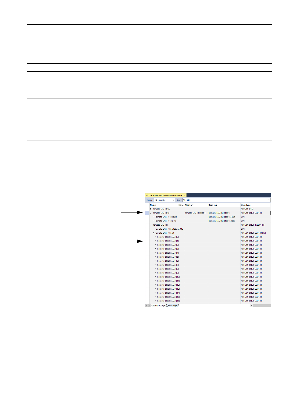
Chapter 9 Communicate with I/O
The individual tag that is created for the I/O
module in remote slot 1.
For example, a remote EtherNet communication module
(Remote_ENT2R) has an I/O module in slot 1.
The entry in the rack-object tag for the remote
communication module that identifies the I/O
module in remote slot 1.
Create Tags for I/O Data
Each I/O tag is automatically created when you configure the I/O module
through the programming software. Each tag name follows this format:
Location:SlotNumber:Type.MemberName.SubMemberName.Bit
This address variable Is
Location Identifies network location
LOCAL = local chassis or DIN rail
ADAPTER_NAME = identifies remote adapter or bridge
SlotNumber Slot number of I/O module in its chassis
Type Type of data:
I = input C = configuration
O = output S = status
MemberName Specific data from the I/O module, such as Data and Fault; depends on the module
SubMemberName Specific data that is related to a MemberName
Bit (optional) Specific point on the I/O module; depends on the size of the I/O module (0…31 for a 32-point module)
If you configure a rack-optimized connection, the software creates a rackobject tag for the remote communication module. You can reference the rackoptimized I/O module individually, or by its element within the rack-object
tag.
96 Rockwell Automation Publication 1756-RM094K-EN-P - October 2020

Communicate with I/O Chapter 9
Controller Ownership
When you choose a communication format, you have to choose whether to
establish an owner or listen-only relationship with the module.
Mode Description
Owner The owner controller writes configuration data and can establish a connection to the module.
Listen-only A controller that uses a listen-only connection only monitors the module. It does not write configuration data and can
only maintain a connection to the I/O module when the owner controller is actively controlling the I/O module.
There is a noted difference in the ownership of input modules versus the
ownership of output modules.
Controlling This Ownership Description
Input modules Owner An input module is configured by a controller that establishes a connection as an owner. This configuring controller
Listen-only Once an input module has been configured (and owned by a controller), other controllers can establish a listen- only
Output modules Owner An output module is configured by a controller that establishes a connection as an owner. Only one owner
Listen-only Once an output module has been configured (and owned by one controller), other controllers can establish listen-
is the first controller to establish an owner connection.
Once an input module has been configured (and owned by a controller), other controllers can establish owner
connections to that module. This lets additional owners to continue to receive multicast data if the original owner
controller breaks its connection to the module. All other additional owners must have the identical configuration
data and identical communication format that the original owner controller has, otherwise the connection attempt
is rejected.
connection to that module. These controllers can receive multicast data while another controller owns the module.
If all owner controllers break their connections to the input module, all controllers with listen-only connections no
longer receive multicast data.
connection can be connected to an output module. If another controller attem pts to establish an owner connection,
the connection attempt is rejected.
only connections to that module. These controllers can receive multicast data while another controller owns the
module. If the owner controller breaks its connection to the output module, all controllers with listen-only
connections no longer receive multicast data.
Rockwell Automation Publication 1756-RM094K-EN-P - October 2020 97

Chapter 9 Communicate with I/O
Runtime/Online Addition of
You can add modules when the controller is in Run mode.
Modules
Network Considerations
ControlNet network You can use:
EtherNet/IP network The EtherNet/IP I/O modules that you add at runtime can be:
• 1756-CN2, 1756-CN2R, 1756-CN2RTXT any series modules.
• 1756-CNB, 1756-CNBR series D or later communication modules.
Digital I/O modules can be added as rack-optimized connections if the parent module is already configured with rack- optimized connections. While you
can add a new digital I/O module to an existing rack-optimized connection, you cannot add rack-optimized connections while online. Digital I/O
modules can also be added as direct connections.
Analog I/O modules can be added only as direct connections.
Disable the Change of State (COS) feature on digital input modules because it can cause inputs to be sent more quickly than the RPI.
If you plan to add large amounts of I/O to the ControlNet network, dedicate one ControlNet network for I/O. For the dedicated ControlNet network, verify
that there is little or no:
• HMI traffic.
• MSG traffic.
• Programming workstations.
If the module has a Real Time Sample (RTS), disable it or set to a rate that is greater than the RPI.
Considerations for 1756-CN2, 1756-CN2R, 1756-CN2RXT Modules
You can add I/O modules until you reach these limits:
• 80% of CPU utilization of the 1756-CN2, 1756-CN2R, or 1756-CN2RXT communication module.
• Less than 400,000 unscheduled bytes per second are displayed in RSNetWorx™ for ControlNet software after the network has been scheduled.
Considerations for 1756-CNB, 1756-CNBR Modules
Requested Packet Intervals (RPIs) faster than 25 ms for unscheduled modules can overload the 1756-CNB or 1756-CNBR communication module. To
avoid the overload, make these considerations:
• Use a NUT of 10 ms or more.
• Keep the SMAX and UMAX values as small as possible.
You can add I/O modules until you reach these limits:
• 75% of CPU utilization of the 1756-CNB or 1756-CNBR communication module.
• Plan for a CPU-use increase of 1…4% of the 1756-CNB or 1756-CNBR module for each I/O module you add, depending on RPI.
• 48 connections on the 1756-CNB or 1756-CNBR communication module.
• Less than 400,000 unscheduled bytes per second are displayed in RSNetWorx for ControlNet software after the network has been scheduled.
• Added to existing rack-optimized connections
• Added to new rack-optimized connections
• Added as direct connections (you can create rack-optimized connections when adding EtherNet/IP I/O modules at runtime)
You can add I/O modules until you reach the limits of the communication module:
1756-EN4TR,
1756-EN4TRXT
Module
• 50,000 pps without
CIP Security
• 25,000 pps with
integrity
• 15,000 pps with
integrity and
confidentiality
512 TCP connections 128 TCP connections 128 TCP connections 64 TCP connections 3 2 TCP Connections 32 TCP Connections
CIP™ connected
messages:
1000 I/O
(1)
528
(1) There are 1000 explicit connections and 528 implicit connections.
98 Rockwell Automation Publication 1756-RM094K-EN-P - October 2020
1756-EN2TR,
1756-EN3TR
20,000 pps 10,000 pps 5000 pps 100,000 pps
256 CIP™ connected
messages
1756-EN2T,
1756-EN2TP,
1756-EN2TXT,
1756-EN2F Module
256 CIP connected
messages
1756-ENBT Module 5069-AENTR,
128 CIP connected
messages
5094-AENTxx
COMPACT 5000 I/O
Ethernet Adapter
(total number of
packets from both
Ethernet Ports)
80 CIP Connected
Messages
5069-AEN2TR
COMPACT 5000 I/O
Ethernet Adapter
100,000 pps
(total number of
packets from both
Ethernet Ports)
320 CIP Connected
Messages

Communicate with I/O Chapter 9
Online Addition of Module and Connection Types
Module Type and
Connection Method
Digital - direct Yes Yes Yes Yes Yes Yes — Yes Yes - 1756 I/O digital
Digital - rack-optimized — — Yes Yes Yes — Yes — Yes - 1756 I/O digital
An alog - di rect Ye s Yes Yes Yes Yes Ye s — Ye s Yes
Ge ne ric th ird -pa rt y - dire ct Ye s Yes Yes Ye s Yes Ye s — Ye s —
1715 Redundant I/O — — Yes Yes — — — — —
1718/1719 I/O — — — — Yes Yes — — Yes – both analog
1756-ENx - no connection Yes Yes Yes Yes — — — — —
1756-ENx - rack-optimized — — Yes Yes — — — — —
Generic EtherNet/IP thirdparty - direct
1788-EN2FFR or
1788-EN2PAR
1788-CN2FFR or
1788-CN2PAR
1794 FLEX I/O — — Yes — Yes Yes — — Yes - Analog output
1734 POINT I/O — — Yes — Yes Yes — — Yes
1734 POINT Guard I/O™ Yes — Yes ——— —— —
5069 Compact 5000 I/O Yes — Yes Yes
5069 Compact 5000 I/O Safety
Modules
5094 FLEX 5000 — — Yes Yes — — — — Yes
5094 FLEX 5000 I/O Safety
Modules
(1) Only supported if adding an entire rack of Compact 5000 I/O modules.
In Local Chassis Remote via an
EtherNet/IP Network
Offline Runtime Offline Runtime Offline Runtime Offline only
—— YesYes — — — — —
—— —— — — Yes Yes —
— — Ye s Yes No Ye s — — —
(1)
Yes — Yes — — — — — —
— — Ye s — — — — — Ye s
Remote via a ControlNet® Network Configure Hold Last
Output State
Scheduled Unscheduled Scheduled Unscheduled
output modules
output modules
and digital modules
modules only
—— —— Yes
Rockwell Automation Publication 1756-RM094K-EN-P - October 2020 99

Chapter 9 Communicate with I/O
Design Considerations for Runtime/Online Addition of Modules
When you design your network, address these considerations to add modules
at runtime.
Design Issue Considerations
I/O modules If you plan to add 1756 I/O modules at runtime, leave space in the local chassis, remote chassis on a ControlNet network, or remote chassis on
Other modules You can add 1757-FFLDC devices remotely via the unscheduled portion of a ControlNet network at runtime.
Input transmission rate Make sure the RPIs work for the data you want to send and receive.
Network topology On a ControlNet network, install spare taps so you can add modules at runtime without disrupting the network. Each tap must be terminated
Network configuration On a ControlNet network, plan which communication can be scheduled or unscheduled.
Network performance You can add modules at runtime until you impact the capacity of the communication module.
an EtherNet/IP network for the I/O modules you want to add.
Make sure the added I/O does not depend on change of state data.
not to ground out the system. Check ControlNet system requirements to determine how ma ny spare taps your network can support.
• In a ControlNet network with redundant cabling, you can break the trunk and add a tap, but redundant cabling is lost during the module
installation.
• In a ControlNet ring, add a drop off the ring or add new nodes off the coax and disrupt only part of the network.
• You could remove an existing node and add a repeater off that drop. Then reconnect the existing node and add any new nodes off the new
segment.
On an EtherNet/IP network, reserve some connectio n points on the switch so that you can connect additional nodes or switches in the future.
On an EtherNet/IP network, all communication is immediate and occurs based on the module RPI (also referred to as unscheduled).
If you know that you need a new chassis with digital modules in the future, configure the network and add it to the I/O configuration tree as
rack optimized. Then inhibit the communication adapter until you need the chassis.
Make sure that you have sufficient communication modules for the connections you plan to add.
100 Rockwell Automation Publication 1756-RM094K-EN-P - October 2020
 Loading...