

Page 1

Rockwell Automation
AutoMax ControlNet
Communication Interface
Module
(Cat. No. O-58820-2)
Major Rev. 2
User Manual
Page 2

Page 2 AutoMax ControlNet Module
Important User Information
Solid state equipment has operational characteristics differing from those
of electromechanical equipment. “Safety Guidelines for the Application,
Installation and Maintenance of Solid State Controls” (Publication SGI-
1.1) describes some important differences between solid state equipment
and hard–wired electromechanical devices. Because of this difference,
and also because of the wide variety of uses for solid state equipment, all
persons responsible for applying this equipment must satisfy themselves
that each intended application of this equipment is acceptable.
In no event will Rockwell Automation be responsible or liable for
indirect or consequential damages resulting from the use or application
of this equipment.
The examples and diagrams in this manual are included solely for
illustrative purposes. Because of the many variables and requirements
associated with any particular installation, Rockwell Automation cannot
assume responsibility or liability for actual use based on the examples
and diagrams.
Rockwell Automation assumes no patent liability with respect to use of
information, circuits, equipment, or software described in this manual.
Reproduction of the contents of this manual, in whole or in part, without
written permission of Rockwell Automation is prohibited.
Throughout this manual we use notes to make you aware of safety
considerations.
Identifies information about practices or circumstances that can lead to
personal injury or death, property damage, or economic loss.
Attentions help you:
• identify a hazard
• avoid the hazard
• recognize the consequences
Important: Identifies information that is especially important for
successful application and understanding of the product.
Microsoft is a registered trademark of Microsoft Corporation.
Windows, Windows 95 and Windows NT are trademarks of Microsoft Corporation.
ControlLogix and Data Highway Plus are trademarks of the Allen-Bradley Company, Inc.
Publication number DSMBCN-UM001B-EN-P February 2003
Page 3

Page 4

INTRODUCTION 9
Who Should Use This Manual? 9
Purpose of this Manual 9
Conventions Used in this Manual 9
Getting Support 10
Reference Documents 10
Requirements 10
MBCN AUTOMAX CONTROLNET MODULE 11
Overview 11
Module Overview 11
Hardware Features 13
7-Segment Display 13
OK LED 14
MAC ID Thumbwheels 14
Serial Configuration Port 14
NAP Port 15
ControlNet Connectors 15
Network Status LEDs 15
7-Segment LED Codes 16
Communication Error 18
INSTALLATION 19
Prevent Electrostatic Discharge 19
Installation and Wiring 20
Connecting to the Network 21
Troubleshooting Wiring Problems 21
QUICK START 22
PROGRAMMING THE MBCN 23
Overview 23
Page 5

AutoMax ControlNet Module Page 5
Memory Overview 23
Configuring Scheduled Connections 24
Creating a Configuration 24
Configuring 1771 I/O 25
Configuring Flex I/O 26
Configuring Scheduled Data with Another MBCN 27
Configuring Scheduled Data with a PLC-5 28
Configuring Scheduled Data with a ControlLogix Processor 29
Setting the Network Properties 32
Downloading the Configuration 32
Putting the MBCN in Run Mode 32
Accessing I/O Data 32
Application Example 33
Multicast Connections 34
MONITORING MODULE OPERATION 35
Status of Each Connection 35
Operating Status 38
Summary of Registers for Monitoring Operation 39
UNSCHEDULED MESSAGING 41
Register Organization 41
AutoMax Application Programming 42
GATEWAY_CMD_OK@ Status Codes 51
Extended Status (EXT_STS) Codes for Command 0F 53
Commands from Remote Nodes 54
Differences from the M/N 57C442 Module Interface 56
VIEWING NETWORK PARAMETERS 57
Current Network Parameters 57
Pending Network Parameters 58
STATE REGISTERS 60
Module State 60
NAM State 60
Keeper State 61
Flash State 62
Serial CONFIG Port State 62
Channel State 63
DIAGNOSTIC COUNTERS 64
Publication number DSMBCN-UM001B-EN-P February 2003
Page 6

Page 6 AutoMax ControlNet Module
Standard ControlNet Counters 64
Module Specific Counters 65
The Error Log 66
ACTIVE NODE LIST 67
ID AREA 68
Vendor ID 68
Device Type 68
Product Code 68
Major Revision 68
Minor Revision 68
Status 68
Serial Number 69
Product Name Length 69
Product Name 69
Current Address 70
MAC ID Switches 70
Summary of ID Area Locations 70
FIRMWARE VERSION INFORMATION 71
USING THE HOST WATCHDOG 72
UPDATING THE FIRMWARE 73
CONVERTING FROM MAJOR REVISION 1 TO 2 76
If you have access to the Reliance MBCN hardware 76
If you have an offline configuration file (*.xc) 76
SPECIFICATIONS 78
SUPPORT 79
Publication number DSMBCN-UM001B-EN-P February 2003
Page 7

AutoMax ControlNet Module Page 7
Table of Figures
Figure 1 Serial Cable Wiring.......................................................................................................................14
Figure 2 LED Status Table..........................................................................................................................16
Figure 3 7-Segment LED Codes .................................................................................................................17
Figure 4 Memory Overview........................................................................................................................24
Figure 5 Connection Status Values .............................................................................................................38
Figure 6 Scanner State Table.......................................................................................................................39
Figure 7 – Adapter (Scheduled Produced Data) State Table.......................................................................39
Figure 8 Summary of Monitor Registers.....................................................................................................40
Figure 9 Summary of Unscheduled Message Registers..............................................................................41
Figure 10 Control and Status Registers.......................................................................................................42
Figure 11 Command Table..........................................................................................................................46
Figure 12 GATEWAY_CMD_OK Status Table.........................................................................................51
Figure 13 Local and Remote Status Table ..................................................................................................52
Figure 14 Extended Status Error Codes Table ............................................................................................54
Figure 15 Unsolicited PLC-5 Commands ...................................................................................................54
Figure 16 Unsolicited Basic Command Set Commands .............................................................................55
Figure 17 Current Network Parameters.......................................................................................................58
Figure 18 Pending Network Parameters......................................................................................................59
Figure 19 Module State Table.....................................................................................................................60
Figure 20 NAM State Table........................................................................................................................61
Figure 21 Keeper State Table......................................................................................................................62
Figure 22 Flash Memory State Table..........................................................................................................62
Figure 23 Serial Config State ......................................................................................................................62
Figure 24 Channel State Table....................................................................................................................63
Figure 25 Standard ControlNet Diagnostic Counters..................................................................................65
Figure 26 Module-Specific Diagnostic Counters........................................................................................66
Figure 27 Active Node Table......................................................................................................................67
Figure 28 Device Status Table ....................................................................................................................68
Figure 29 Device Status, Bits 4-7................................................................................................................69
Figure 30 ID Locations Table .....................................................................................................................70
Figure 31 Firmware Versions Table............................................................................................................71
Publication number DSMBCN-UM001B-EN-P February 2003
Page 8

Page 9

This introduction covers the following topics:
• who should use this manual
• the purpose of the manual
• contents of the manual
• conventions used in the manual
• getting support
Who Should Use This Manual?
Use this manual if you are responsible for designing, installing,
programming or troubleshooting systems that are based on AutoMax
Control using the MBCN ControlNet module (O-58820-2) with major
revision 2 firmware.
You should have a basic understanding of AutoMax products. You
should understand Allen Bradley PLC-5s and ControlLogix PLCs and be
familiar with using ControlNet I/O modules on the ControlNet network.
Introduction
Purpose of this Manual
This manual shows you how to install and use the MBCN ControlNet
module. It describes the procedures to install, configure, and operate the
MBCN ControlNet module.
Conventions Used in this Manual
The following conventions are used throughout this manual:
• bulleted lists, such as this one, provide information, not procedural
steps
• numbered lists provide sequential steps
• bold type is used for emphasis
courier font is used for text you should type
•
• hexadecimal numbers are shown with a trailing ‘h’, for example,
1234h
• titles for menu items, dialog boxes, etc. in software are shown in
italics
• addresses that refer to a single byte within an AutoMax register are
shown with a trailing ‘L’ or ‘H’ to indicate the low or high byte of
the register.
• T=>O means ControlNet target-to-originator; O=>T means
originator-to-target. The originator is the node that opens the
connection to the target.
• RSNetWorx means RSNetWorx for ControlNet
Page 10

Page 10 AutoMax ControlNet Module
Getting Support
Refer to page 79 for information on how to obtain support for the MBCN
module.
For support on the AutoMax processor or programming software, contact
Rockwell Automation or your local distributor.
Reference Documents
For information on using RSNetWorx, refer to:
• RSNetworx ControlNet Getting Results, Publication Number 9399CNETGR, Catalog number 9357-CNETL3
For information on ControlNet, refer to one of the following:
• ControlNet Specification, available from ControlNet International,
www.controlnet.org
• IEEE 518 Guide for the Installation of Electrical Equipment to
Minimize Electrical Noise Input to Controllers
• ControlNet user manual, publication 1786-2.12
, approximate cost US$350
Requirements
RSNetWork for ControlNet version 3.21 and above includes support for
configuring the MBCN.
MBCN firmware version 1.10 and above requires RSNetWorx for
ControlNet for configuration.
The MBCN must be running firmware version 1.10 or above to be used
with ControlFlash.
To use the connection status information, you need RSNetWork for
ControlNet version 4.11 or above and firmware version 2.1 or above on
the MBCN.
Refer to page 73 for information on updating the firmware in the MBCN.
Refer to page 76 for information on converting a revision 1 MBCN to a
revision 2 MBCN in RSNetWorx for ControlNet.
Publication number DSMBCN-UM001B-EN-P February 2003
Page 11

Overview
Module Overview
AutoMax ControlNet Module Page 11
MBCN AutoMax ControlNet Module
This chapter contains the following information:
• module overview
• a summary of hardware features
• a description of how the hardware works
The MBCN module makes it possible for an application running in an
AutoMax Controller to communicate with and control ControlNet I/O
devices. The MBCN can also exchange data with other processors over
the ControlNet network using scheduled produced and consumed data.
The MBCN uses the standard AutoMax memory-mapped interface to the
host processor.
All I/O data is mapped into AutoMax registers 16384-32767. You can
select the register assignment for the data for each connection or have the
register assignment created automatically when you create the I/O
configuration.
The module:
• supports up to 127 scheduled connections, up to 480 words per
connection
• supports a maximum of 16 Kbytes total input data
• maps input data into AutoMax Processor registers 16384-24575
• supports a maximum of 16 Kbytes total output data
• maps output data into AutoMax Processor registers 24576-32767
• provides global status on all originator to target (O=>T) connections
and global status on all target to originator (T=>O) connections
• provides status on each connection, in AutoMax registers 1536215614, two 16-bit words per connection. You map the location of the
status information for a connection using RSNetWorx. This requires
major revision 2 of the MBCN firmware and RSNetWorx for
ControlNet 4.11 or later. Major revision 1 of the MBCN firmware
does not support status on individual connections
You use RSNetWorx for ControlNet to configure the I/O devices being
scanned and all scheduled produced and consumed connections.
The MBCN maintains standard ControlNet diagnostic counters, as well
as additional diagnostic counters, to monitor MBCN operation and to
diagnose problems.
The MBCN maintains an active node list.
Publication number DSMBCN-UM001B-EN-P February 2003
Page 12

Page 12 AutoMax ControlNet Module
The MBCN can send unscheduled messages to other nodes on the
network, and receive and respond to unscheduled messages from other
nodes, using PLC-5 PCCC commands. The MBCN emulates the
AutoMax interface on the M/N 57C442 Data Highway Plus module.
Publication number DSMBCN-UM001B-EN-P February 2003
Page 13
Hardware Features
AutoMax ControlNet Module Page 13
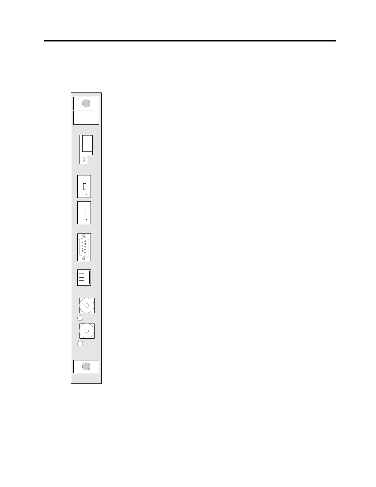
The main hardware features of the MBCN are:
• 7-segment display
MBCN
O-58820
Fault
Code
MAC ID
OK
• OK LED
• switches to set the MBCN’s ControlNet address
• serial config port for updating the MBCN firmware
• ControlNet NAP port
• ControlNet BNC connectors
• network status LEDs
10
These are described in detail in the following sections
1
Config NAP
A
COM
B
COM
7-Segment Display
The MBCN has a 7-segment LED to indicate status. Refer to page 16 for
a summary of 7-segment display codes.
Publication number DSMBCN-UM001B-EN-P February 2003
Page 14

Page 14 AutoMax ControlNet Module
6
7
8
9
OK LED
The MBCN contains a hardware watchdog that monitors operation of the
MBCN hardware and software. The hardware watchdog times out only
when there is a catastrophic hardware or firmware failure on the MBCN.
The green OK LED is on when the hardware watchdog is OK and is off
if the watchdog times out.
NOTE: The hardware watchdog is NOT the same as the host watchdog.
See page 72 for information on using the host watchdog.
MAC ID Thumbwheels
Use the two thumbwheels labelled MAC ID to set the MBCN’s address
on ControlNet. The upper thumbwheel sets the most significant digit;
the lower thumbwheel sets the least significant digit.
To maximize network efficiency and reduce network overhead, you
usually assign ControlNet addresses consecutively, starting at 1.
NOTE: 0 is not a valid address.
The MBCN reads the thumbwheels only at power-up. You must power
down and power back up for changes in the thumbwheel settings to be
recognized.
Serial Configuration Port
The thumbwheel switches must be positioned in the center of the detent.
You can verify the switch settings by displaying register 32.
The serial CONFIG port on the front of the MBCN can be used to:
• update the firmware on the MBCN
• update the FPGA (field programmable gate array) configuration on
the MBCN
Note: you normally update both using ControlFlash over ControlNet.
The serial cable for a standard PC COM port must have lines 2 and 3
swapped. It does not require any handshaking. Pins 2 and 3 are wired
the same as a PC 9-pin COM port. A cable is provided with the MBCN
when shipped in the original packaging.
1
2
3
4
5
1
6
2
7
3
8
4
9
5
Figure 1 Serial Cable Wiring
Connect to the serial port using any communication software. For
example, you can use the HyperTerminal program supplied with
Windows. The MBCN serial port supports a baud rate of 57.6 Kbaud,
with no parity, 8 data bits and 1 stop bit.
Refer to page 73 for information on updating MBCN firmware.
Publication number DSMBCN-UM001B-EN-P February 2003
Page 15
NAP Port
AutoMax ControlNet Module Page 15
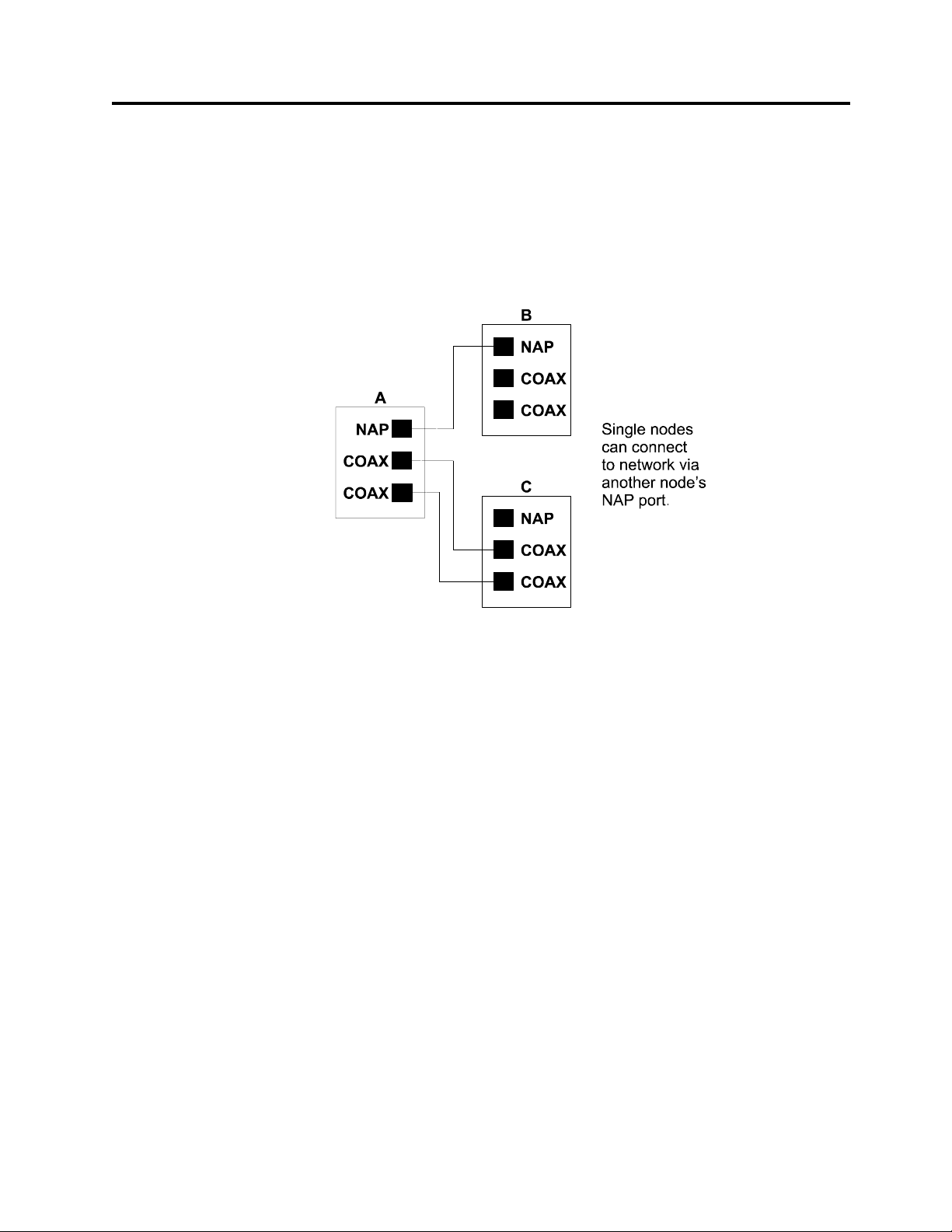
The MBCN has a standard ControlNet NAP port to allow a transient
node to connect to the ControlNet network.
Use the NAP port on the MBCN if you want to attach a transient node to
the network and you do not want to rewire the network. Do not connect
any node to the network using both the NAP port and a coax path at the
same time. The following figure shows how to correctly connect a
transient node.
ControlNet Connectors
Network Status LEDs
NAP Connection 1
You can also use the NAP port on the MBCN to attach the MBCN to an
existing network, by connecting to the NAP port on a node on the
existing network.
The NAP cable has 8 conductors and a shield, with RJ-45 connectors at
each end. The cables are reversed from one end of the cable to the other,
so that 1->8, 2->7, etc. Maximum cable length is 10 m.
Connect the MBCN to the ControlNet network using the standard
ControlNet BNC connectors.
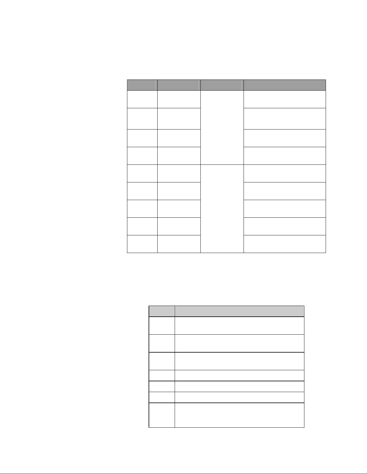
There is one network status (COM) LED for each network connector.
The network status LEDs display the following states, using the priority
scheme shown. If more than one condition exists, the LEDs display the
state with the highest priority.
When using redundant cabling, both LEDs should be green. One will be
brighter; this is the active channel.
Publication number DSMBCN-UM001B-EN-P February 2003
Page 16
Page 16 AutoMax ControlNet Module
The LEDs do not reflect the state of the NAP port. If you connect the
MBCN to the network via the NAP port, the two network status LEDs
flash red together.
Priority State How to view Cause
1
(highest)
2 Both steady
3 Alternating
4 Alternating
5 Steady off Channel disabled or channel
6 Flashing
7 Flashing
8 Flashing
9
(lowest)
Both steady
off
red
red/green
red/off
red/green
red/off
green/off
Steady green
Viewed
together
Viewed
Independently
Reset or no power
Failed link interface
Fatal error on MBCN
Self test
Bad node configuration, such
as duplicate address
not supported
Invalid link configuration,
such as address > UMAX
Link fault or no MAC frames
received
Temporary channel error, or
listen only
Normal operation
Figure 2 LED Status Table
7-Segment LED Codes
Value Meaning
1 NAM not attached. There are no other nodes
on the network.
2 Keeper faulted master. The MBCN schedule
needs to be updated using RSNetWorx.
3 Keeper faulted backup. The MBCN schedule
needs to be updated using RSNetWorx.
4 Keeper change
5 Keeper faulted change
6 Keeper temporary state
b Inactive. The MBCN is online but has no
scheduled connections and is not sending or
receiving messages.
Publication number DSMBCN-UM001B-EN-P February 2003
Page 17

AutoMax ControlNet Module Page 17
Value Meaning
C Communication error
d One or more connections requires a schedule.
Use RSNetWorx to schedule all connections.
E Bad thumbwheel value
P Scanning in program mode
U Firmware on the MBCN is being updated
H Hardware on the MBCN is being updated.
r Module requires reset, usually after an update.
Cycle power to the rack that contains the
MBCN.
.0 Module checksum failure
.1 Local RAM data failure
.2 Local RAM address failure
.3 Local RAM FF fill failure
.4 Local RAM 00 fill failure
.5 Code copy failure
.6 Shared RAM failure
.7 Shared RAM address failure
.8 Shared RAM FF fill failure
.9 Shared RAM 00 fill failure
.A Module startup failure
.b Bootup shell activate prompt
.C Board reset failure
.d AutoMax watchdog failure
.E Power fail
.F Module hardware failure (jabber inhibit, host
watchdog). Cycle power to see if the problem
disappears. If it does not, replace the MBCN.
Off Scanning OK in run mode
Figure 3 7-Segment LED Codes
LED codes that start with a dot are hardware failures and usually indicate
that the MBCN has suffered a fatal hardware or firmware failure.
Contact technical support.
Publication number DSMBCN-UM001B-EN-P February 2003
Page 18

Page 18 AutoMax ControlNet Module
Communication Error
The following are common causes for communication error ( C ) to be
displayed on the 7-segment LED:
• The MBCN couldn’t open one or more connections. Look at the
status for each connection in RSNetWorx or on the MBCN
• The MBCN has refused a connection or has returned an error to an
unscheduled message. Look at the status for each connection using
RSNetWorx or the status registers on the MBCN or look at the status
of the connections on other nodes that have connections to the
MBCN.
• The MBCN is sending unscheduled messages that are failing.
Publication number DSMBCN-UM001B-EN-P February 2003
Page 19

Prevent Electrostatic Discharge
The MBCN is sensitive to electrostatic discharge.
ATTENTION: Electrostatic discharge can damage integrated circuits
or semiconductors if you touch backplane connector pins. Follow these
guidelines when you handle the module:
• Touch a grounded object to discharge static potential
AutoMax ControlNet Module Page 19
Installation
• Wear an approved wrist-strap grounding device
• Do not touch the backplane connector or connector pins
• Do not touch circuit components inside the module
• If available, use a static-safe work station
• When not in use, keep the module in its static-shield packaging
This chapter contains the information necessary to:
• install the MBCN in the AutoMax rack
• connect the MBCN to the ControlNet network
• use the MBCN serial port
• understand the MBCN LEDs
Publication number DSMBCN-UM001B-EN-P February 2003
Page 20
Page 20 AutoMax ControlNet Module
Installation and Wiring
The user is responsible for conforming to all applicable local, national,
and international codes. Wiring practices, grounding, disconnects, and
over-current protection are of particular importance. Failure to observe
this precaution could result in severe bodily injury or loss of life.
To reduce the possibility of electrical noise interfering with the operation
of the control system, exercise care when installing the wiring from the
control system to the external devices. For detailed recommendations,
refer to IEEE 518.
Step 1. Stop any application tasks that may be running.
This equipment is at line voltage when AC power is connected.
Disconnect and lock out all ungrounded conductors of the AC power
line. Failure to observe this precaution could result in severe bodily
injury or loss of life.
DANGER
DANGER
WARNING
Inserting or removing a module may result in unexpected machine
motion. Power to the machine should be turned off before inserting or
removing a module. Failure to observe these precautions could result in
bodily injury.
Step 2. Turn off all power to the rack. All power to the rack as well as
all power leading to the rack should be off.
CAUTION
This module contains static sensitive components. Careless handling
can cause severe damage. Do not touch the connectors on the back of
the module. When not in use, the module should be stored in an antistatic bag. The plastic cover should not be removed. Failure to observe
this precaution could result in damage to or destruction of the
equipment.
Step 3. Take the MBCN out of its shipping container. Take it out of the
anti-static bag, being careful not to touch the connectors on the back of
the MBCN.
Publication number DSMBCN-UM001B-EN-P February 2003
Page 21

Step 4. Set the MBCN’s address on the network using the thumbwheels.
Make sure the thumbwheels are centered on the detents.
Step 5. Insert the MBCN in the desired slot in the rack, making sure that
it is well seated in the rack. Use a screwdriver to secure the MBCN in
the rack.
Step 6. Connect the MBCN to the ControlNet network using the BNC
connectors on the front of the MBCN.
Step 7. Turn on power to the rack.
Connecting to the Network
Connect the MBCN to the ControlNet network like any other ControlNet
node, using a ControlNet tap to connect to the network trunkline. The
drop cable from the tap to the MBCN should be 1 m long. The
recommended trunk cable type is RG6. (It is recommended that you use
standard ControlNet network taps available through Allen-Bradley.)
The physical ends of the network trunkline should be terminated with
75-ohm terminators. There should be two and only two terminators on
the network.
AutoMax ControlNet Module Page 21
The MBCN supports redundant cabling.
Ensure that the address for the MBCN is less than or equal to the
maximum unscheduled address (UMAX) configured on the network.
NOTE: 0 is not a valid address.
If the MBCN is being used as a scanner or for scheduled I/O, make sure
the address is less than or equal to the maximum scheduled address
(SMAX) configured on the network.
To maximize efficiency on the ControlNet network, assign consecutive
node addresses to nodes on the network, with the nodes exchanging
scheduled data at the lowest addresses.
Troubleshooting Wiring Problems
If the MBCN does not go active on the network:
• Check cabling for correct wiring to the MBCN.
• Check network termination. Only the two nodes at the physical ends
of the network should have terminating resistors. There should be
two and only two terminators on the network.
• Check the network configuration. Make sure UMAX is high enough
to include this node.
• Check that you haven’t duplicated the address of another node on the
network.
• Check that the thumbwheels have been read correctly by displaying
register 32.
Publication number DSMBCN-UM001B-EN-P February 2003
Page 22

Page 22 AutoMax ControlNet Module
The following steps describe the procedure for using the MBCN as a
scanner. The sections that follow describe the procedures and registers
in more detail.
Step Description Refer to
Quick Start
page:
Step 1. Use RSNetWorx to create a configuration that
contains the I/O devices the MBCN is to scan
and the scheduled produced and consumed
connections for the MBCN.
Step 2. Download the configuration to the MBCN. 32
Step 3. Check the NAM state for online. 60
Step 4. Put the MBCN in run mode. 32
Step 5. Verify you can read input data and set output
data, check connection status, and so on.
24
32,35
Publication number DSMBCN-UM001B-EN-P February 2003
Page 23
Overview
Memory Overview
AutoMax ControlNet Module Page 23
Programming the MBCN
This section is a guide for configuring and programming the MBCN.
Configure the scheduled connections using RSNetWorx. The
configuration you create contains all the I/O devices to be scanned, and
all the scheduled produced and consumed connections on the MBCN, the
network parameters and the schedule for all updates.
This section starts with some general information, then describes the
MBCN memory layout in detail, with information about the interface
between your application and the MBCN, and the organization of the
tables on the MBCN.
The MBCN contains 64 Kbytes (32768 16-bit registers) of shared
memory that can be accessed through the AutoMax rack backplane by
application tasks running on an AutoMax processor. The following table
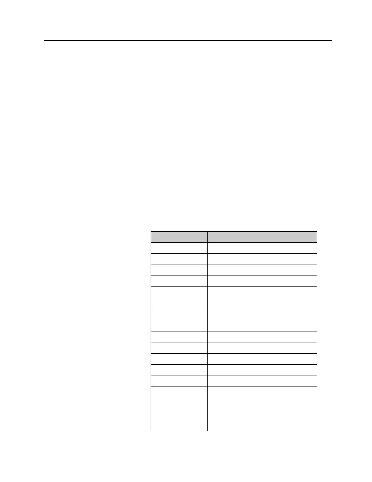
shows the general organization of the shared memory.
AutoMax Registers Description
0-63 Status and control
5 Module control register
64-7383 Unscheduled data
9216-9245 ID area
9247 Channel state
9248-9263 Active node list
9280-9292 Pending network parameters
9304-9316 Current network parameters
9336-9339 Error log
9344-9401 Diagnostic counters
9466 Serial port state
9468-9471 Revision information
9472 Module state
9473 NAM state
9474-9475 Host watchdog
9476 Keeper state
9477 Flash state
Publication number DSMBCN-UM001B-EN-P February 2003
Page 24

Page 24 AutoMax ControlNet Module
AutoMax Registers Description
9478 Link timeout
15362-15614 Status for each connection
15744-15760 Overall status information
16384-24575 Scheduled receive data
24576-32767 Scheduled transmit data
Figure 4 Memory Overview
Configuring Scheduled Connections
The MBCN can act as a ControlNet scanner to scan I/O modules. As
well, scheduled connections can be configured to exchange data with
other scanner nodes on the network.
You use RSNetWorx to configure your network. The following sections
briefly describe how to configure commonly occurring devices. For
detailed information, refer to the RSNetWorx documentation and online
help.
Creating a Configuration
You can use RSNetWorx as an offline or online configuration tool. In
most cases you will use it online. The instructions that follow describe
using RSNetWorx online. They assume that RSNetWorx and RSLinx
have been installed, along with any hardware required to communicate
with the ControlNet network.
1. Run RSNetWorx.
2. Create a new configuration using the File/New command.
3. Put RSNetWorx online using the Network/Online command.
4. Select a path to the network. RSNetWorx should go online and
display the devices it finds on the network.
5. Click on the MBCN you are configuring to select it, right click on it
and select Scanlist Configuration from the menu that appears.
RSNetWorx asks whether you want to switch to Edit Mode. Click
Yes.
6. The MBCN Scanlist Configuration Tool opens. There are two tabs –
the Connection Configuration tab, which shows all the connections
for the device you are configuring, and the Connection Status tab,
which shows the status of those connections.
7. Select the Connection Configuration tab to create connections.
The device you are configuring, in this case the MBCN, is shown
highlighted. The other devices are shown as a list.
Publication number DSMBCN-UM001B-EN-P February 2003
Page 25

Configuring 1771 I/O
AutoMax ControlNet Module Page 25
8. To create a connection to another device, right click on that device in
the list and select Insert Connection from the menu that appears.
9. To create a target on the MBCN to which another device can
connect, right click on the MBCN and select Insert Target for
Connections from the menu.
The following sections provide simple examples of how to create
connections for specific types of devices. For deatiled information, refer
to the online help for RSNetWorx for ControlNet and the documentation
for the devives you are connecting.
Adding Analog Modules
When RSNetWorx goes online, it scans the network and finds 1771
adapters and chassis but it cannot detect analog modules in those chassis.
If you want to create connections to those devices, you must first add
them to the chassis before you start the MBCN Scanlist Configuration.
You do not have to add discrete modules.
To add analog modules:
1. From the main RSNetWorx window, double click on the 1771
chassis. The View Chassis window appears. Drag modules from the
Hardware list to the appropriate 1771 chassis slot. When you have
added all required modules, click OK.
2. Right click on the MBCN you are configuring and select Scanlist
Configuration to start the Scanlist Configuration tool.
Creating the Connection to Discrete I/O
To create a connection to the 1771 discrete data:
1. Right click on the adapter and select Insert Connection. The
Connection Properties dialog box opens.
2. Set the Connection Name to Discrete Exclusive Owner.
3. Set the Requested Packet Interval to the desired update rate. The RPI
must be greater than or equal to the network update time (NUT).
This time will be the update time for all the discrete modules in the
rack. The default values for the RPIs is the network update time
(NUT).
4. Set the Input and Output sizes to the desired values.
5. RSNetWorx assigns the Input Address, Output Address and Status
Address automatically if Enable automatic addressing on insert is
turned on. If you want to manually assign these addresses, enter the
values.
6. Click OK to complete the configuration.
Publication number DSMBCN-UM001B-EN-P February 2003
Page 26

Page 26 AutoMax ControlNet Module
Creating Connections to Analog I/O Modules
Note: You must always create a connection to the discrete I/O in the
chassis, even if you are interested only in the analog modules in the
chassis.
1. Right click on the analog module and select Insert Connection.
2. Set the Connection Name to Discrete Exclusive Owner.
3. Set the Requested Packet Interval to the desired update rate. The RPI
must be greater than or equal to the network update time (NUT).
4. Set the Input, Output and Configuration sizes to the desired values.
Refer to the documentation for the module for details. Most modules
can be configured in more than one way – the values you choose
here depend on the type of module and how you want to configure it.
5. RSNetWorx assigns the Input Address, Output Address and Status
Address automatically if Enable automatic addressing on insert is
turned on. If you want to manually assign these addresses, enter the
values.
6. If the module has a Configuration Setting tab, select it and enter
appropriate values for the configuration data. Refer to the module
documentation for details.
Configuring Flex I/O
7. Click OK to complete the configuration.
You create a single connection for all the discrete modules in a Flex rack,
and individual connections to the analog modules.
You do not have to create a connection to the discrete modules to create
a connection to an analog module.
When you put RSNetWorx online, it should find and display the modules
in the Flex rack.
Discrete Connection
To create the connection to the discrete I/O in the MBCN Scanlist
Configuration:
1. Right click on the Flex ControlNet adapter and select Insert
Connection. The Connection Properties dialog opens.
2. Set the Connection Name to Exclusive owner.
3. Set the Requested Packet Interval to the desired update rate. The RPI
must be greater than or equal to the network update time (NUT).
This time will be the update time for all the discrete modules in the
rack.
4. RSNetWorx automatically sets the Input and Output sizes to the
maximum values. You can reduce these sizes if the higher slots are
Publication number DSMBCN-UM001B-EN-P February 2003
Page 27

AutoMax ControlNet Module Page 27
not occupied by discrete modules. For example, if the highest slot
occupied by an output module is slot 7, you can reduce the output
size from 8 to 7.
5. RSNetWorx assigns the Input Address, Output Address and Status
Address automatically if Enable automatic addressing on insert is
turned on. If you want to manually assign these addresses, enter the
values
6. You can set how output modules behave on lost communications or
in program mode on a slot by slot basis. First click the Rack
Specifications tab and make sure that Include in Output is Yes for the
module. Click the Advanced tab and set the parameters to the
desired values.
7. Click OK to accept the connection.
Analog Connection
You do not need to create a connection to the discrete I/O in the Flex
rack to create a connection to analog modules in the rack.
1. Set the Connection Name to Discrete Exclusive Owner.
2. Set the Requested Packet Interval to the desired update rate. The RPI
must be greater than or equal to the network update time (NUT).
3. Refer to the documentation for the individual module for detailed
information on possible values for the Input, Output and
Configuration sizes.
4. RSNetWorx assigns the Input Address, Output Address and Status
Address automatically if Enable automatic addressing on insert is
turned on. If you want to manually assign these addresses, enter the
values
5. Click on the Configuration Setting tab to set module configuration
data such as input or output range, safe state data, etc.
6. You can set how the outputs behave on lost communications or in
program mode on a slot by slot basis. First click the Rack
Specifications tab and make sure that Include in Output is Yes for
the module. Click the Advanced tab and set the parameters to the
desired values.
7. Click OK to accept the connection.
Configuring Scheduled Data with Another MBCN
1. Right click on the MBCN from which you want to obtain scheduled
data and select Insert Connection from the menu.
2. The Connection Name should be Consume Data From
Publication number DSMBCN-UM001B-EN-P February 2003
Page 28

Page 28 AutoMax ControlNet Module
3. Set the Requested Packet Interval to the desired update rate. The RPI
must be greater than or equal to the network update time (NUT).
4. Set the input size to the number of words of data you want to receive
from the destination MBCN.
5. RSNetWorx assigns the Input Address, Output Address and Status
Address automatically if Enable automatic addressing on insert is
turned on. If you want to manually assign the addresses, enter the
values.
6. Click OK to accept the settings you have entered.
RSNetWorx automatically creates a matching Produce Data target on the
destination MBCN.
Configuring Scheduled Data with a PLC-5
Produced Data on the PLC-5, Consumed on the MBCN
In the Scanlist Configuration for the MBCN:
1. Right click on the PLC-5 from which the MBCN is obtaining data
and select Insert Connection. If necessary, switch to Edit Mode.
The Connection Properties dialog opens.
2. Set the Connection Name to Receive Data From.
3. RSNetWorx automatically assigns the Consume Buffer ID. If the
automatic value is incorrect, change it to the correct value.
4. Set the Requested Packet Interval to the desired update rate. The RPI
must be greater than or equal to the network update time (NUT).
5. Set the Input Size to the number of words of data you wish the
PLC-5 to produce.
6. RSNetWorx assigns the Input Address, Output Address and Status
Address automatically if Enable automatic addressing on insert is
turned on. If you want to manually assign these addresses, enter the
values.
7. Click OK to accept the settings.
RSNetWorx automatically creates a matching produce target in the
PLC-5. Start the Scanlist Configuration tool for the PLC-5 and confirm
that this is so.
Produced Data on the MBCN, Consumed on the PLC-5
1. In the main RSNetWorx window, right click on the PLC-5 and select
Scanlist Configuration. The Scanlist Configuration tool for the
PLC-5 opens.
2. Right click on the MBCN from which you want the PLC-5 to obtain
scheduled data and select Insert Connection.
Publication number DSMBCN-UM001B-EN-P February 2003
Page 29

AutoMax ControlNet Module Page 29
3. Set the Connection Name to Consume Data From.
4. RSNetWorx assigns the Producer ID automatically. If necessary,
change the value.
5. Set the Requested Packet Interval to the desired update rate. The RPI
must be greater than or equal to the network update time (NUT).
6. Set the Input Size to the number of words of data you wish the
MBCN to produce.
7. RSNetWorx assigns the Input Address, Output Address and Status
Address automatically if Enable automatic addressing on insert is
turned on. If you want to manually assign these addresses, enter the
values.
8. Click OK to accept the settings.
RSNetWorx automatically creates a matching produce target in the
MBCN. Start the Scanlist Configuration tool for the MBCN and confirm
that this is so.
Configuring Scheduled Data with a ControlLogix Processor
To exchange scheduled data with a ControlLogix processor, you must
first create user-defined data types for the data in the ControlLogix, then
create tags of the types you have created. This must be done offline in
RSLogix 5000.
Produced Data on the ControlLogix, Consumed on the MBCN
Use the following steps to create a produced tag in RSLogix 5000:
1. Expand the Data Types item in the tree, right click on User-Defined,
and select New Data Type...
In the dialog box that appears:
2. Give the new type a name, for example, ProdTagType, and
optionally a Description.
3. Create a member for the data type. This member should be an array
of INTs of the size of data that you want to transfer. The maximum
size is 240 words, but this may be further restricted by the network
schedule.
4. Click OK to accept the data type.
5. Expand the Controller in the tree. Right click on Controller Tags
and select Edit Tags. RSLogix 5000 displays a list of the existing
controller tags
6. Right click on an empty entry in the list and select Edit Tag
Properties.
In the dialog box that appears:
7. Give the tag a Name and optionally a description.
Publication number DSMBCN-UM001B-EN-P February 2003
Page 30

Page 30 AutoMax ControlNet Module
8. For the Data Type, select the user-defined data type you created
earlier.
9. For Tag Type, check Produced and set the number of consumers to
an appropriate value (at least 1 but more if other nodes will be
consuming this data).
10. Click the OK button.
Save your program and download it to the ControlLogix processor.
In the RSNetWorx Scanlist Configuration for the MBCN:
1. Right click on the ControlLogix processor and select Insert
Connection.
2. In the Communication Parameters area, enter the name of the
produced tag (not the user defined data type) in the Value field.
3. Set the Requested Packet Interval to the desired update rate. The RPI
must be greater than or equal to the network update time (NUT).
4. Set the input size to the number of words of data in the produced tag.
5. RSNetWorx assigns the Input Address, Output Address and Status
Address automatically if Enable automatic addressing on insert is
turned on. If you want to manually assign these addresses, enter the
values.
6. Click OK to accept the settings.
Produced Data on the MBCN, Consumed on the ControlLogix
To have the ControlLogix processor consume data from the MBCN, you
must first add the MBCN to the I/O Configuration in the ControlLogix.
This must be done offline.
1. Right click on I/O Configuration in the tree and select New Module.
2. Select the appropriate ControlNet bridge module to match the
hardware in the ControlLogix chassis and click OK.
3. Give the ControlNet bridge module a Name and optionally a
Description.
4. Set the slot to the slot the bridge module occupies in the ControlNet
chassis.
5. Set the Node to match the switch settings on the bridge module.
6. Click Finish to accept the bridge module.
7. Right click on the ControlNet bridge module you just created and
select New Module.
8. Select 1785-PLC5C (the MBCN emulates a PLC-5) and click OK,
9. Give the module a Name and optionally a Description.
Publication number DSMBCN-UM001B-EN-P February 2003
Page 31

AutoMax ControlNet Module Page 31
10. Set the Node to the MBCN address on the ControlNet network.
11. Click Finish.
Use the following steps to create a consumed tag in RSLogix 5000:
1. Expand the Data Types item in the tree, right click on User-Defined,
and select New Data Type... In the dialog box that appears:
2. Give the new type a name, for example, ConsTagType, and
optionally a Description.
3. Create members for the data type. The first member should be a
DINT (this entry contains status information). The other member
should be an array of INTs of the size of data that you want to
transfer. The maximum size is 240 words, but this may be further
restricted by the network schedule.
4. Click OK to accept the data type.
5. Expand the Controller in the tree. Right click on Controller Tags
and select Edit Tags. RSLogix 5000 displays a list of the existing
controller tags
6. Right click on an empty entry in the list and select Edit Tag
Properties. In the dialog box that appears:
7. Give the tag a Name and optionally a description.
8. For Tag Type, check Consumed.
9. For Producer, select the MBCN from the list.
10. Set the Remote Instance to match the value in the MBCN (see
below).
11. Set the Requested Packet Interval to the desired update rate. The RPI
must be greater than or equal to the network update time (NUT).
12. For the Data Type, select the user-defined consumed data type you
created earlier.
13. Click the OK button to accept the tag.
14. Save your program and download it to the ControlLogix processor.
In RSNetWorx you must create a target produced connection on the
MBCN. In the Scanlist Configuration:
1. Right click on the MBCN and select Insert Target for Connections.
2. Set the Connection Name to Produce Data.
3. Set the Producer ID to match the Remote Instance in the
ControlLogix.
4. Set the Output Size to match the data size (size of the data array, not
including the DINT) in the consumed tag in the ControlLogix.
Publication number DSMBCN-UM001B-EN-P February 2003
Page 32

Page 32 AutoMax ControlNet Module
5. RSNetWorx assigns the Input Address, Output Address and Status
Address automatically if Enable automatic addressing on insert is
turned on. If you want to manually assign these addresses, enter the
values.
6. Click OK to accept the connection.
Example:
To produce 120 words of data on the MCN and consume them on the
ControlLogix, create a produce connection of size 120 on the MBCN,
then create a consumeddata type in the ControlLogix that consists of a
DINT and an array of 120 INTs. Create a tag in the ControlLogix that
uses this data type.
Setting the Network Properties
From the main RSNetWorx window, select Network/Properties… Set
the Network Update Time (NUT) in ms, the Max. Scheduled Address
(SMAX), the Max. Unscheduled Address (UMAX), and the Media
Redundancy. If necessary, you can select the Media Configuration tab
and add any repeaters, etc. on your network.
Downloading the Configuration
When all the configuration information has been entered into
RSNetWorx, select Save to save and download the configuration. The
Save Configuration dialog box appears. Select Optimize and re-write
schedule for all connections and click OK. Answer Yes to break
connections and download.
Putting the MBCN in Run Mode
Before you put the MBCN in run mode, your program should check the
NAM (network attachment monitor) state to confirm that the MBCN is
online. Refer to page 60 for information on how to do this.
Put the MBCN in run mode by setting bit 1 in register 5.
The MBCN goes out of run mode when you do a stop all in the AutoMax
or when you clear bit 1 in register 5.
Accessing I/O Data
You assign the location for the data for each connection either manually
or automatically in the Scanlist Configuration tool. If you assign
locations manually, RSNetWorx checks that there are no overlaps.
Publication number DSMBCN-UM001B-EN-P February 2003
Page 33

Application Example
AutoMax ControlNet Module Page 33
There is usually some header information included with the data for each
connection. The amount varies with the type of device the MBCN is
connected to. RSNetWorx displays input and output sizes in the form
9(6). This means that the connection uses 9 words in total, with 6 words
of data and 3 words of header. If the address assigned to the connection
is 16384, this means that addresses 16384, 16385 and 16386 contain the
header, and that addresses 16387-16392 contain the 6 words of data.
Use this information to obtain the data addresses to use in your AutoMax
program.
In the following example, the MBCN occupies slot 9 in an AutoMax
rack.
In AutoMax Programming Executive Version 3.0 and later, you define
these registers using the Variable Configurator.
If you are using AutoMax Programming Executive Version 2.1 or earlier,
you define these registers using IODEF statements in the rack
configuration task.
0100 TASK CNSCAN[TYPE=BASIC, PRIORITY=11, SLOT=0, CRITICAL=FALSE]
0110 IODEF CN_RUN@[SLOT=9, REGISTER=5, BIT=1]
0120 IODEF NAMSTATE%[SLOT=9, REGISTER=9473]
0300 IODEF INP_WRD_0%[SLOT=9, REGISTER=16393]
0310 IODEF INP_WRD_1%[SLOT=9, REGISTER=16394]
0400 IODEF OUT_WRD_0%[SLOT=9, REGISTER=24588]
0410 IODEF OUT_WRD_1%[SLOT=9, REGISTER=24589]
32767 END
The following BASIC program checks the NAM state for the attached
state before it puts the MBCN in run mode and starts accessing data, then
copies an input word to an output, and increments another output word.
0001 REM SAMPLE PROGRAM
0100 COMMON CN_RUN@
0110 COMMON NAMSTATE%
0120 COMMON INP_WRD_0%
0130 COMMON INP_WRD_1%
0140 COMMON OUT_WRD_0%
0150 COMMON OUT_WRD_1%
0160 COMMON REC_STAT1%
Publication number DSMBCN-UM001B-EN-P February 2003
Page 34

Page 34 AutoMax ControlNet Module
0200 IF NAMSTATE% = 12 THEN GOTO 300 \!ATTACHED
0210 DELAY 1 TICKS
0220 GOTO 200 \! WAIT FOR ONLINE
0300 CN_RUN@ = 1 \! PUT THE MBCN IN RUN
0400 OUT_WRD_0% = INP_WRD_0% \!COPY INPUT WORD
0410 IF OUT_WRD_1% > 10000 THEN OUT_WRD_1%=0\!LOOP
0420 OUT_WRD_1% = OUT_WRD_1% + 1 \!INCREMENT OUTPUT
0430 DELAY 1 TICKS
0500 GOTO 400
32767 END
Multicast Connections
To create listen-only or input-only connections to devices to consumed
data, use the previous procedures but set the Connection Name to Listen
Only or Input Only.
RSNetWorx automatically sets the output size to 0 for these connections.
Publication number DSMBCN-UM001B-EN-P February 2003
Page 35

There are various registers on the MBCN that can be used to monitor the
operating status.
Status of Each Connection
You can use RSNetWorx to view the status of each connection.
Start the Scanlist Configuration for the MBCN and click on the
Connection Status tab. RSNetWorx displays Success for connections
that are operating correctly or gives an explanation for connections that
are not.
The MBCN also contains a status table that shows the status of each
connection, in registers 15362 to 15615.
Each entry consists of two 16-bit registers. The first is the General
Status, the second is the Extended Status. You assign the location of the
entry for a connection in RSNetWorx.
The following table shows possible status values.
AutoMax ControlNet Module Page 35
Monitoring Module Operation
General
Status,
hex
00 Service completed successfully.
01 0100 Connection in Use or Duplicate Forward Open.
01 0103 Transport Class and Trigger combination not
01 0106 Ownership Conflict
01 0107 Connection not found at target application. Could
01 0108 Invalid Connection Type. Indicates a problem with
01 0109 Invalid Connection Size. Check the sizes of
01 0110 Device not configured
01 0111 RPI not supported. May also indicate problem with
Extended
Status,
hex
Explanation
supported
be a buffer ID mismatch for scheduled produced and
consumed connections.
either the Connection Type or Priority of the
Connection.
scheduled produced and consumed connections.
the connection time-out multiplier.
01 0113 Connection Manager cannot support any more
connections
01 0114 Either the Vendor Id or the Product Code in the key
segment did not match the device
Publication number DSMBCN-UM001B-EN-P February 2003
Page 36

Page 36 AutoMax ControlNet Module
General
Status,
hex
Extended
Status,
hex
Explanation
01 0115 Product Type in the key segment did not match the
device
01 0116 Major or Minor Revision information in the key
segment did not match the device
01 0117 Invalid Connection Point. Could be the wrong
device type, device mismatches with scheduled
produced and consumed connections, etc.
01 0118 Invalid Configuration Format
01 0119 Connection request fails since there is no controlling
connection currently open.
01 011A Target Application cannot support any more
connections
01 0203 Connection cannot be closed since the connection
has timed out
01 0204 Unconnected Send timed out waiting for a response.
The destination device doesn’t exist (invalid
address, device turned off, etc.)
01 0205 Parameter Error in Unconnected Send Service
01 0206 Message too large for Unconnected message
service
01 0301 No buffer memory available
01 0302 Network Bandwidth not available for data
01 0303 No Tag filters available
01 0304 Not Configured to send real-time data
01 0311 Port specified in Path Segment Not Available
01 0312 Link Address specified in Path Segment Not
Available
01 0315 Invalid Segment Type or Segment Value in Path
01 0316 Path and Connection not equal in close
01 0317 Either Segment not present or Encoded Value in
Network Segment is invalid. The connection hasn’t
been scheduled. Run RS NetWorx.
01 0318 Link Address to Self Invalid
01 0319 Resources on Secondary Unavailable
02 n/a Connection Manager resources are unavailable to
handle service request
Publication number DSMBCN-UM001B-EN-P February 2003
Page 37

AutoMax ControlNet Module Page 37
General
Status,
hex
03* n/a Invalid connection number specified by the
04 Zero
05 Zero
07 n/a Connection has been lost. This is used by the
08 n/a Connection Manager does not support the
Extended
Status,
hex
Based
Word
Offset
Based
Word
Offset
Explanation
Get_Connection_Data service. This is also returned
by the Search_Connection_Data service if the
specified connection is not found.
Segment Type in path is invalid. The Extended
Status shall be the word offset (0 based) to the word
in the path where the error occurred. The offset
starts at the first word after the path size. This error
shall not be returned if an error occurs when parsing
the Connection Path.
Destination in path is invalid. The Extended Status
shall be the word offset (0 based) to the word in the
path where the error occurred. The offset starts at
the first word after the path size. This error shall not
be returned if an error occurs when parsing the
Connection Path.
Get/Set Services when they are made through a
connection.
requested Service.
09 Index to
Element
0C Optional Service cannot be performed while Object is in
10 Optional Service cannot be performed while Device is in
11 n/a Response data too large. This is used by the get
13 n/a Not enough data was received.
14 Attribute Id Attribute specified in FIND service is not supported
Error in Data Segment. Extended Status shall be
index to where the error was encountered in the
Data Segment. The Configuration Revision Number
if present in the Data Segment shall always be index
1. If the error occurs with the Get/Set Services, then
the extended status indicates the attribute number
that failed.
current state. The 1st word of Extended Status may
optionally contain the object’s current state.
This could occur if you are making changes while in
run mode.
current state. The 1st word of Extended Status may
optionally contain the device’s current state.
This could be caused by an offline unscheduled
device, or the keeper is in a faulted state.
services to indicate the amount of data requested
was too large to fit into the response buffer.
by Connection Manager
Publication number DSMBCN-UM001B-EN-P February 2003
Page 38

Page 38 AutoMax ControlNet Module
General
Status,
hex
15 n/a Too much data was received.
25 0114 Either the Vendor Id or the Product Code in the key
25 0115 Product Type in the key segment did not match the
25 0116 Major or Minor Revision information in the key
26 n/a Invalid path size
D0 01 Connection is closed or stopped
D0 02 Connection open is pending.
D0 03 Connection close is pending
Extended
Status,
hex
Explanation
segment did not match the device. Used if the Key
Segment was contained in the path.
device. Used if the Key Segment was contained in
the path.
segment did not match the device. Used if the Key
Segment was contained in the path.
(Target connection) Nothing is talking to this
connection.
Figure 5 Connection Status Values
Operating Status
The following registers contain information about the operation of the
MBCN.
Number of Instances
Register 15748 contains the number of connections currently configured.
This includes both originator-to-target (O=>T) and target-to-originator
(T=>O) connections.
Register 15751 contains the number of originator instances.
Overall Status
Register 15745 contains the overall status. You can use bits in this
register to quickly determine the overall status of MBCN operations.
If bit 0 is set, all I/O and scheduled consume and scanner (originator)
connections are operating with no errors.
If bit 8 is set, all scheduled produced (target) connections are operating
with no errors.
Publication number DSMBCN-UM001B-EN-P February 2003
Page 39

AutoMax ControlNet Module Page 39
If bit 3 is set, one or more originator instances does not have a schedule.
Run RSNetWorx and schedule the network by enabling edits and doing a
save.
Scanner State
Register 15754 shows the current scanner state.
Value Scanner State
0 Idle
1 Active, in program mode
2 Active, in run mode
Figure 6 Scanner State Table
This register is read-only. The state is Idle only when you are
downloading a configuration.
Adapter State
Register 15755 shows the current state of scheduled produced data
connections.
Value State
0 Idle
1 Enabled
Figure 7 – Adapter (Scheduled Produced Data) State Table
This register is read-only.
Summary of Registers for Monitoring Operation
Refer to the preceding sections for detailed information on each of these
registers.
AutoMax
Registers
15362 -
15615
15745 Status Overall status
15748 NumInstances Number of instances currently
Name Description
Connection
status
Status of each connection
configured
15751 NumOrigInsts Number of originator instances
15754 ScanState Current scanner state
Publication number DSMBCN-UM001B-EN-P February 2003
Page 40

Page 40 AutoMax ControlNet Module
AutoMax
Registers
15755 AdapState Current adapter state
Name Description
Figure 8 Summary of Monitor Registers
Publication number DSMBCN-UM001B-EN-P February 2003
Page 41

Register Organization
AutoMax ControlNet Module Page 41
Unscheduled Messaging
The MBCN supports unscheduled messaging to other nodes on the
ControlNet network. It emulates the interface of the M/N 57C442 Data
Highway Plus module. It uses PCCC commands to communicate with
other nodes on the network.
This section describes how the messaging interface is organized in the
MBCN and provides examples of how the MBCN is accessed by the
application software. For more detailed information on programming,
refer to the AutoMax Programming Language manuals.
The MBCN supports sending messages on the local network only, not
through bridge modules.
The following table shows the memory organization. The following
sections describe the different register areas in more detail.
Registers Description
4 – 63 Status and control registers
64 – 1063 Binary file B3
1088 – 2087 Binary file B4
2088 – 3087 Binary file B5
4384 – 5383 Integer file N7
5384 – 6383 Integer file N8
6384 – 7383 Integer file N9
Figure 9 Summary of Unscheduled Message Registers
WARNING
REGISTERS AND BITS THAT ARE DESCRIBED AS "READ
ONLY" OR FOR "SYSTEM USE" ONLY MUST NOT BE WRITTEN
TO BY THE USER. WRITING TO THESE REGISTERS AND BITS
MAY RESULT IN IMPROPER SYSTEM OPERATION. FAILURE
TO OBSERVE THIS PRECAUTION COULD RESULT IN BODILY
INJURY.
Publication number DSMBCN-UM001B-EN-P February 2003
Page 42

Page 42 AutoMax ControlNet Module
R/W Register Description
R/W 22 Response Poll period, in units of 1/8 second. This
R/O 32 Node address (1-99). The value comes from the
R/O 33 Extended Status (EXT STS) error code.
R/O 61 Module Software Revision Level. A value of 100
register is used by the GATEWAY_CMD_OK@
function to compute the time interval to poll for
command complete. The default value is 1, which
corresponds to a response polling period of 0.125
seconds.
thumbwheel switches on the faceplate and is updated
only on power-up. The MBCN will not begin to
communicate on the network until the node address is
properly set.
NOTE: The on-line Monitor function in the AutoMax
Programming Executive software can display the node
address in either decimal or hexadecimal notation.
indicates version 1.00, and so on. This is the same as
the version that scrolls on the 7-segment LED at
power-up.
R/O 62-63 Interface module ID (ASCII 'GTWY').
AutoMax Application Programming
The sections that follow describe how to configure registers in the
MBCN's shared memory and how to initiate commands from the MBCN.
Link configuration and application programming examples are provided.
Variable Configuration AutoMax application tasks communicate with
the Interface module by referencing registers in the shared memory.
These registers must first be configured using the AutoMax
Programming Executive software.
In AutoMax Programming Executive Version 3.0 and later, you define
these registers using the Variable Configurator.
If you are using AutoMax Programming Executive Version 2.1 or earlier,
you define these registers using IODEF statements in the rack
configuration task.
Figure 10 Control and Status Registers
Publication number DSMBCN-UM001B-EN-P February 2003
Page 43

AutoMax ControlNet Module Page 43
The format for the IODEF statement (used only in V2.1 and earlier) is as
follows:
nnnn IODEF variable_name [SLOT=slot number, &
REGISTER=register number, BIT=bit number]
where:
• nnnn = configuration task line number
• variable_ name = integer or boolean variable. Double integer
variables can be used but should be avoided because of the
possibility that all 32 bits will not transfer in one operation.
WARNING
IF YOU USE DOUBLE INTEGER VARIABLES IN THIS
INSTANCE, YOU MUST IMPLEMENT A SOFTWARE
HANDSHAKE BETWEEN THE TRANSMITTER AND RECEIVER
TO ENSURE THAT BOTH THE LEAST SIGNIFICANT AND MOST
SIGNIFICANT 16 BITS HAVE BEEN TRANSMITTED BEFORE
THEY ARE READ BY THE RECEIVING APPLICATION
PROGRAM. FAILURE TO OBSERVE THIS PRECAUTION COULD
RESULT IN BODILY INJURY.
• slot number = slot number of the module in the rack. This number
may range from 0 to 15.
• register number = AutoMax register number on the module. Register
numbers correspond to 16-bit words on the module.
• bit number = bit number of the I/O point in the register. Bit numbers
range from 0 to 15. Bit numbers are specified for Boolean variables
only.
Any variables contained in the rack configuration are accessible by any
task on any AutoMax Processor in the rack. When AutoMax variables
are referenced in AutoMax tasks, the data is directly obtained from or
written to the register image on the module. The data storage for an
AutoMax variable mapped to an A-B register will always exist in the
module's shared memory.
The registers in the MBCN's register image may be displayed using the
AutoMax Programming Executive Monitor I/O function.
Publication number DSMBCN-UM001B-EN-P February 2003
Page 44

Page 44 AutoMax ControlNet Module
Application Programming
Read and write commands from the MBCN are initiated from a BASIC
application task by executing the GATEWAY_CMD_OK@ function:
GATEWAY_CMD_OK@(status%, cmd_code%, slave_node%, &
slave_reg$, master_var!, num_regs%)
where:
• status is an integer variable representing the location where the status
resulting from the operation is stored. Refer to page 51 for a list of
status values.
• cmd_code is a variable name or expression of type integer
representing the PCCC command sent by the module. The
commands are described on page 46.
Any other commands result in a status of 1 (invalid operation) being
returned.
slave_node is variable name or expression of type integer containing the
destination address (in decimal or hexadecimal). This is the address on
your network.
slave_reg is a variable name or expression of type string that specifies
the starting register number an the target device. For commands 3, 4, 5,
6, and 7, this is a logical address represented as an ASCII string for
PLC-5 controllers. For commands 1 and 2, this argument contains 4
octal digits, for example, "0200" (word offset). For command 5 (ReadModify-Write), this argument can contain up to ten ASCII addresses
separated by commas. The address must exist at the target node.
master_var is a variable name or expression (usually via the BASIC
language
The VARPTR! Function, of type double integer, represents the physical
address of the starting register on the module to be read from/written to.
num_regs is a variable name or expression of type integer that defines:
• for Word Range Read/Write (command 3 or 4) or for Typed
Read/Write (commands 6 or 7), the number of registers to be
transferred, from 1 to 1000;
• for Read-Modify-Write (command 5), the number of addresses to be
written, in the range 1 to 10;
• for Unprotected Read/Write (command 1 or 2), the number of
registers to be transferred, from 1 to 100.
The GATEWAY_CMD_OK@ function returns true if the command was
successfully completed. If the function returns false, the returned status is
an error code. Refer to page 51 for the error codes returned by the
GATEWAY_CMD_OK@ function.
Multiple tasks can access the MBCN.
Publication number DSMBCN-UM001B-EN-P February 2003
Page 45

AutoMax ControlNet Module Page 45
NOTE: If more than four tasks try to initiate messages at the same time,
error code '22' is returned to the additional tasks attempting accesses.
If you are using AutoMax Programming Executive software version 2.1
or earlier, any required registers must be defined using IODEFs in the
configuration task. If you are using AutoMax Programming Executive
software version 3.0 or later, these registers are defined using the
Variable Configurator within the Programming Executive. The following
example illustrates one method of enabling the MBCN.
Example:
In the configuration, define the following registers:
RESP_TIME% [SLOT=4, REGISTER=22]
The application could initialize the MBCN as follows:
30 RESP_TIME%=2\!GATEWAY_CMD_OK@ should poll for
response every 250 ms.
Publication number DSMBCN-UM001B-EN-P February 2003
Page 46

Page 46 AutoMax ControlNet Module
Commands Initiated by the Module
The commands described in figure 13 can be used by the AutoMax
Processor in the GATEWAY_CMD_OK@ function to initiate a
command on the MBCN.
GATEWAY_CMD_OK@
Command Code
1 Unprotected Read CMD = 01, FNC = n/a
2 Unprotected Write CMD = 08, FNC = n/a
3 Word Range Read CMD = 0F, FNC = 01
4 Word Range W rite CMD = 0F, FNC = 00
5 Read-Modify-Write CMD = 0F, FNC = 26
6 PLC-5 Typed Read CMD = 0F, FNC = 68
7 PLC-5 Typed Write CMD = 0F, FNC = 67
Description PCCC Function
Figure 11 Command Table
Commands 1 and 2 come from the basic command set and are accepted
by all Allen-Bradley processors. For PLC-5 processors, compatibility
files must exist. Refer to Allen-Bradley documentation for more
information. Command 1, Unprotected Read, transfers a block of data
from the target registers at the remote address to the specified AutoMax
registers on the module. Data can be transferred to any file in the PLC-5
data image area. The data is stored in the specified registers on the
module. A maximum of 100 registers can be transferred in a single
request. The transfer cannot cross file boundaries.
Command 2, Unprotected Write, transfers a block of data from the
specified AutoMax registers on the module to the target registers at the
destination address. The data must already exist in the registers on the
module. Data can be transferred from any file in the PLC-5 data image
area. A maximum of 100 registers can be transferred in a single request.
The transfer cannot cross file boundaries.
Commands 3, 4, 5, 6 and 7 come from the PLC-5 command set.
Commands 3, 4, 5, 6 and 7 are accepted by PLC-5 processors. For
commands 3, 4, 5, 6, and 7, only logical addresses represented as ASCII
strings are supported.
Command 3, Word Range Read, transfers a block of data from the target
registers at the remote address to the specified AutoMax registers on the
module. Data can be transferred to any file in the PLC-5 data image area.
The data is stored in the specified registers on the module. A maximum
of one file (1000 registers) can be transferred in a single request. The
transfer cannot cross file boundaries.
Publication number DSMBCN-UM001B-EN-P February 2003
Page 47

AutoMax ControlNet Module Page 47
Command 4, Word Range Write, transfers a block of data from the
specified AutoMax registers on the module to the target registers at the
destination address. The data must already exist in the registers on the
module. Data can be transferred from any file in the PLC-5 data image
area. The data is stored in the specified registers on the module. A
maximum of one file (1000 registers) can be transferred in a single
request. The transfer cannot cross file boundaries.
Command 5, Read-Modify-Write, sets or resets specified bits in
specified registers in the data table at the remote address. The data (AND
and OR masks) must already exist in the registers on the module. A
maximum of ten registers can be modified in a single request.
NOTE: The A-B controller at the remote address may change the states
of the original bits in memory before this command (command 5) can
write the word back to memory. Therefore, some bits may
unintentionally be overwritten. To help prevent this, we suggest that you
use this command to write into the storage area of a programmable
controller's data table, and have the controller read the word only, not
control it.
Command 6, Typed Read, transfers a block of data from the target
registers at the remote address to the specified AutoMax registers on the
module. Data can be transferred to any file in the PLC-5 data image area.
The data is stored in the specified registers on the module. A maximum
of one file (1000 registers) can be transferred in a single request. The
transfer cannot cross file boundaries.
Command 7, Typed Write, transfers a block of data from the specified
AutoMax registers on the module to the target registers at the destination
address. The data must already exist in the registers on the module. Data
can be transferred from any file in the PLC-5 data image area. The data
is stored in the specified registers on the module. A maximum of one file
(1000 registers) can be transferred in a single request. The transfer
cannot cross file boundaries.
In cases where any of the commands above generates multiple messages
on the network (for example, reading or writing more registers than can
fit in one message) the module takes care of formatting and generating
the messages required. The GATEWAY_CMD_OK@ command is
complete when a reply is received for the last message in the group.
Example 1: Command 3, Word Range Read
In the example below, the module is reading 100 words from file N7:0 in
the PLC at node address 3. The data read is stored in the local B3 file.
The variable B3BASE% is defined in the rack configuration.
10 COMMON B3BASE% \! Represents the physical address of &
the starting register on the &
module to be read from
Publication number DSMBCN-UM001B-EN-P February 2003
Page 48

Page 48 AutoMax ControlNet Module
20 LOCAL DST% \! The address of the destination node &
21 LOCAL STS% \! The location where the status &
22 LOCAL SZE% \! The number of registers to be &
23 LOCAL CMD% \! The PCCC command sent by the module
30 DST% = 3
31 STS% = 0
32 SZE% = 100
33 CMD% = 3
40 IF NOT GATEWAY_CMD_OK@(STS%, CMD%, DST%, "N7:0", &
VARPTR!(B3BASE%), SZE%) THEN 20000 \! process errors &
at line 20000
Example 2: Command 4, Word Range Write
In the example below, the module is writing 100 words from the local N7
file to the file address N10:10 in the PLC at node address 7. The variable
N7BASE% is defined in the rack configuration.
on the local ControlNet network
resulting from the operation is stored
transferred
10 COMMON N7BASE% \!Represents the physical address of &
the starting register on the &
module to be written to
20 LOCAL DST% \!The address of the destination node &
on the local network
21 LOCAL STS% \! The location where the status &
resulting from the operation is
stored
22 LOCAL SZE% \! The number of registers to be &
transferred
23 LOCAL CMD% \! The PCCC command sent by the module
30 DST% = 7
31 STS% = 0
32 SZE% = 100
33 CMD% = 4
40 IF NOT GATEWAY_CMD_OK@(STS%, CMD%, DST%, "Nl0:10",&
VARPTR!(N7BASE%), SZE%) THEN 20000 \!process errors &
at line 20000
Example 3: Command 6, Typed Read
In the example below, the module is reading 100 words from file N7:0 in
the PLC at node address 3. The data read is stored in the local B3 file.
The variable B3BASE% is defined in the rack configuration.
10 COMMON B3BASE% \! Represents the physical address of &
the starting register on the &
Publication number DSMBCN-UM001B-EN-P February 2003
Page 49

AutoMax ControlNet Module Page 49
module to be read from
20 LOCAL DST% \! The address of the destination node &
on the local ControlNet network
21 LOCAL STS% \! The location where the status &
resulting from the operation is stored
22 LOCAL SZE% \! The number of registers to be &
transferred
23 LOCAL CMD% \! The PCCC command sent by the module
30 DST% = 3
31 STS% = 0
32 SZE% = 100
33 CMD% = 6
40 IF NOT GATEWAY_CMD_OK@(STS%, CMD%, DST%, "N7:0", &
VARPTR!(B3BASE%), SZE%) THEN 20000 \! process errors &
at line 20000
Example 4: Command 7, Typed Write
In the example below, the module is writing 100 words from the local N7
file to the file address N10:10 in the PLC at node address 7. The variable
N7BASE% is defined in the rack configuration.
10 COMMON N7BASE% \! Represents the physical address of &
the starting register on the &
module to be written to
20 LOCAL DST% \! The address of the destination node &
on the local network
21 LOCAL STS% \! The location where the status &
resulting from the operation is stored
22 LOCAL SZE% \! The number of registers to be &
transferred
23 LOCAL CMD% \! The PCCC command sent by the module
30 DST% = 7
31 STS% = 0
32 SZE% = 100
33 CMD% = 7
40 IF NOT GATEWAY_CMD_OK@(STS%, CMD%, DST%, "N10:10",&
VARPTR!(N7BASE%), SZE%) THEN 20000 \!process errors &
at line 20000
Example 5: Command 5, Read-Modify-Write
In the example below, the module writes to three addresses in a PLC,
N7:0, N7:2, and N7:4. The AND/OR mask pairs are stored in three
consecutive pairs of registers starting at B3BASE%. The variable
B3BASE% is defined in the rack configuration.
10 COMMON B3BASE% \! Represents the physical address of &
the starting register on the &
Publication number DSMBCN-UM001B-EN-P February 2003
Page 50

Page 50 AutoMax ControlNet Module
20 LOCAL DST% \! The address of the destination node &
21 LOCAL STS% \! The location where the status &
22 LOCAL SZE% \! The number of registers to be &
23 LOCAL CMD% \! The PCCC command sent by the module
30 DST% = 7
31 STS% = 0
32 SZE% = 3
33 CMD% = 5
40 IF NOT GATEWAY_CMD_OK@(STS%, CMD%, DST%, &
"N7:0,N7:2,N7:4", VARPTR!(B3BASE%), SZE%) & THEN 20000 &
Example 6: Command 1, Unprotected Read
In the example below, the module is reading 100 words from address 200
octal in the PLC at node address 7. The data read is stored in the local B3
file; the variable B3BASE% is defined in the rack configuration.
module to be read from
on the local network
resulting from the operation is stored
transferred
\! process errors at line 20000
10 COMMON B3BASE% \! Represents the physical address of &
the starting register on the &
module to be read from
20 LOCAL DST% \! The address of the destination node &
on the local network
21 LOCAL STS% \! The location where the status &
resulting from the operation is stored
22 LOCAL SZE% \! The number of registers to be transferred
23 LOCAL CMD% \! The PCCC Plus command sent by the module
30 DST% = 7
31 STS% = 0
32 SZE% = 100
33 CMD% = 1
40 IF NOT GATEWAY_CMD_OK@(STS%, CMD%, DST%, "200", &
VARPTR!(B3BASE%), SZE%) THEN 20000 \! process errors &
at line 20000
Example 7: Command 2, Unprotected Write
In the example below, the module is writing 100 words from the local N7
file to the file address 1234 octal in the PLC at node address 7. The
variable N7BASE% is defined in the rack configuration.
10 COMMON N7BASE% \! Represents the physical address of &
the starting register on the &
module to be written to
Publication number DSMBCN-UM001B-EN-P February 2003
Page 51

20 LOCAL DST% \! The address of the destination node &
21 LOCAL STS% \! The location where the status &
22 LOCAL SZE% \! The number of registers to &
23 LOCAL CMD% \! The command sent by the module
30 DST% = 7
31 STS% = 0
32 SZE% = 100
33 CMD% = 2
40 IF NOT GATEWAY_CMD_OK@(STS%, CMD%, DST%, "1234", &
VARPTR!(N7BASE%),SZE%) THEN 20000 \! process errors &
GATEWAY_CMD_OK@ Status Codes
The following codes are written to the variable defined as the "status"
parameter in the GATEWAY_CMD_OK@ function used to initiate
PCCC network data transfers from an AutoMax application task.
AutoMax ControlNet Module Page 51
on the local network
resulting from the operation is stored
be transferred
at line 20000
Code, hex Description
0 Operation successful
1 Invalid operation
3 Invalid length
4 Invalid offset
5 Invalid length + offset
6 Invalid destination
8 Invalid data type
9 Invalid route (equal to own address)
B Inconsistent response
C Module not enabled
20 Parameter specifying destination address is
invalid
21 module not found or inaccessible
22 No available data path
41 Could not open a connection
42 Timeout opening a connection.
Figure 12 GATEWAY_CMD_OK Status Table
Local and Remote Status (STS) error codes are written to the upper byte.
If the first digit is "1", the STS code is local; if the first digit is "3", the
STS code is remote.
Publication number DSMBCN-UM001B-EN-P February 2003
Page 52

Page 52 AutoMax ControlNet Module
Code, hex Description
11 Destination memory full, cannot accept
command now
12 Destination did not acknowledge command
13 Network contention, possible duplicate node or
bad cabling
14 Local port is disconnected, or no other node
found
15 Timeout waiting for a reply message
16 Duplicate node detected
17 Node is offline
18 Hardware fault
1D Transaction number mismatch
1E Duplicate transaction number
31 Illegal command or format
32 Host is malfunctioning and will not
communicate
33 Remote node host is missing, disconnected, or
shut down
34 Host could not complete function due to
hardware fault
35 Addressing problem or memory protected
rungs
36 Function disallowed due to command
protection selection
37 A-B Processor is in program mode
38 Compatibility mode file missing or
communication zone problem
39 Remote node cannot buffer command
3A (not used)
3B Remote node problem due to download
3C Cannot execute command due to active IPBs
3D (not used)
3E (not used)
3F There is an error code in the Extended Status
register (register 33 on the module). See
section 0.
Figure 13 Local and Remote Status Table
Publication number DSMBCN-UM001B-EN-P February 2003
Page 53

Extended Status (EXT_STS) Codes for Command 0F
If the value in the upper byte of the GATEWAY_CMD_OK@ "status"
parameter variable is 3F, then there is a value in the upper byte of the
extended status register (register 33 on the module) that supplies further
information.
The following table shows possible values for the extended status error
code.
Code, hex Description
0 (not used)
1 A field has an illegal value
2 Less levels specified in address than minimum
for any address
3 More levels specified than system supports
4 Symbol not found
AutoMax ControlNet Module Page 53
5 Symbol is of improper format
6 Address doesn't point to something usable
7 File is wrong size
8 Cannot complete request; situation has
changed since the start of the command
9 Data or file is too large
A Transaction size plus word address is too large
B Access denied, improper privilege
C Condition cannot be generated; resource is not
available
D Condition already exists; resource is already
available
E Command cannot be executed
F Histogram overflow
10 No access
11 Illegal data type
12 Invalid parameter or invalid data
13 Address reference exists to deleted area
14 Command execution failure for unknown
reason; possible PLC-3 histogram overflow
15 Data conversion error
Publication number DSMBCN-UM001B-EN-P February 2003
Page 54

Page 54 AutoMax ControlNet Module
Commands from Remote Nodes
The module responds to the following incoming commands from remote
nodes:
Code, hex Description
16 Scanner not able to communicate with 1771
rack adapter
17 Adapter cannot communicate with module
18 1771 module response was not valid
19 Duplicated label
1A File is open; another node owns it
1B Another node is the program owner
1C-FF (not used)
Figure 14 Extended Status Error Codes Table
Command Function Description
0F 68 Typed Read / Read Block
0F 67 Typed Write / Write Block
0F 01 Word Range Read / Read Block
0F 00 Word Range Write / Write Block
0F 26 Read-Modify-Write /Write Bit
Figure 15 Unsolicited PLC-5 Commands
For the PLC-5 commands shown, the module supports both logical
ASCII addresses and logical binary addresses.
The module accepts PLC-5 typed read, typed write, word range read and
word range write commands from ControlLogix PLCs.
Publication number DSMBCN-UM001B-EN-P February 2003
Page 55

AutoMax ControlNet Module Page 55
Basic Command Set Commands
Command Function Description
02 N/A Protected Bit Write
00 N/A Protected Write
05 N/A Unprotected Bit Write
01 N/A Unprotected Read
08 N/A Unprotected Write
Figure 16 Unsolicited Basic Command Set Commands
The commands shown write directly to or read directly from file N7 on
the module. The address field is used as an offset into the file. If the
address does not exist, the module returns an error.
Unprotected writes are processed in the same manner as Protected writes.
Publication number DSMBCN-UM001B-EN-P February 2003
Page 56

Page 56 AutoMax ControlNet Module
Differences from the M/N 57C442 Module Interface
If you are modifying an existing application for the 57C442 Data
Highway Plus module to work on the ControlNet module, you should be
aware of the following differences between the interface on the two
modules.
• There is no global data on ControlNet.
• There are fewer integer files on the ControlNet module. The
ControlNet module has three integer files (N7-N9). The Data
Highway Plus module has twelve (N7-N18).
• There is no DH+ active node list on the ControlNet module. Use the
ControlNet active node list instead.
• The ControlNet module doesn't accept unsolicited PCCC diagnostic
commands.
• You don't have to explicitly put the ControlNet module online.
• You don't have to set the message timeout; the ControlNet module
sets it based on network parameters.
• The ControlNet module doesn’t support DH+ diagnostic counters
(use the ControlNet counters instead).
• The ControlNet module doesn’t support the DH+ station name.
Publication number DSMBCN-UM001B-EN-P February 2003
Page 57

The network parameters include the network update time (NUT), the
maximum scheduled address (SMAX), the maximum unscheduled
address (UMAX), and the network redundancy (channel A only, Channel
B only, or both).
There are additional network parameters that depend on the devices on
the network, the network media type and length, and so on.
The MBCN has tables that contain the values assigned. Refer to the
ControlNet specification for detailed information on what these registers
contain.
In normal operation, it will not be necessary to use these registers.
Current Network Parameters
An application can use the following registers to view the current
network parameters. These registers should be regarded as read-only.
NOTE: The active network keeper periodically sends a packet called the
TUI that indicates the status of the network keeper to the other nodes on
the network.
AutoMax ControlNet Module Page 57
Viewing Network Parameters
Name Register Description
CurNutLen 9304
CurSMax 9305 Maximum scheduled address. This is
CurUMax 9306 Maximum unscheduled address. This
CurSlotTime 9307 Slot Time. This is the maximum time
CurBlanking 9308 Minimum gap between frames (in 1.6
CurGbStart 9309
CurGbCenter 9310
CurModulus 9312 Modulus (always 127). This is different
Network update time (NUT) in 10 µs
increments
the highest address allowed to
transmit scheduled data.
is the highest address allowed to
transmit unscheduled data.
to wait for a node to transmit (in 1 µs
ticks)
µs ticks) (always 6)
Guard Band Start Time (in 10 µs ticks)
Guard Band Center Time (in 10 µs
ticks). This is when the moderator
node sends the moderator packet.
from the scheduling modulus.
CurGbPrestart 9313
Publication number DSMBCN-UM001B-EN-P February 2003
Guard Band PreStart Time (in 10 µs
ticks)
Page 58

Page 58 AutoMax ControlNet Module
Name Register Description
CurTuiUniqueID 9314-9315 Keeper CRC. This is the last Table
CurTuiStatus 9316 TUI Status of last good TUI from
Pending Network Parameters
During an online parameter change, the following registers show the
values of the network parameters that are about to replace the current
network parameters. These values are used internally by the MBCN.
Name Register Description
unique ID (TUI) value (heard from
valid TUI from the network).
network. If bit 0 is set, it indicates that
channel B is configured; if bit 1 is set,
it indicates that channel A is
configured. Refer to the ControlNet
specification for the remaining bits.
Figure 17 Current Network Parameters
PndNutLen 9280 Network update time (NUT) in 10 us
increments
PndSMax 9281 Maximum scheduled address. This is
the highest address allowed to
transmit scheduled data.
PndUMax 9282 Maximum unscheduled address. This
is the highest address allowed to
transmit unscheduled data
PndSlotTime 9283 Slot Time. This is the maximum time
to wait for a node to transmit (in 1 us
ticks)
PndBlanking 9284 Minimum gap between frames (in 1.6
us ticks) (always 6)
PndGbStart 9285 Guard Band Start Time (in 10 us ticks)
PndGbCenter 9286 Guard Band Center Time (in 10 us
ticks). This is when the moderator
node sends the moderator packet
PndModulus 9288 Modulus (always 127). This is different
from the scheduling modulus
PndGbPrestart 9289 Guard Band PreStart Time (in 10 us
ticks)
PndTuiUniqueID 9290-9291 Keeper CRC. This is the Table unique
Id (TUI) value after the current network
change is complete
Publication number DSMBCN-UM001B-EN-P February 2003
Page 59

AutoMax ControlNet Module Page 59
Name Register Description
PndTuiStatus 9292 TUI Status that the MBCN will send if it
becomes the master keeper after the
network change is complete.
Figure 18 Pending Network Parameters
Publication number DSMBCN-UM001B-EN-P February 2003
Page 60

Page 60 AutoMax ControlNet Module
The MBCN maintains several registers that indicate the state of various
operations on the MBCN.
Module State
The Module State register (9472) indicates the current overall state of the
MBCN. It can have one of three values.
Name Value Description
CRD_STE_OFFLINE 41h MBCN is offline and not trying
CRD_STE_ONLINE 42h MBCN is trying to attach to the
CRD_STE_ERROR E1h Fatal error
State Registers
to attach to the network
network
Figure 19 Module State Table
NAM State
The Network Attachment Monitor (NAM) allows nodes to
non-disruptively join a working network. Refer to section 9.9 of the
ControlNet Specification for detailed information on the Network
Attachment Monitor.
The NAMState register (9473) indicates the current Network Attachment
Monitor state. If the NAM state is not
NAM_ATTACHED, the 7-segment
LED displays “1”. The following table lists possible NAM states.
Name Value Meaning
NAM_GO_OFFLINE 00h Transitional state in going
offline
NAM_BAD 01h Duplicate node or address >
UMAX
NAM_WAIT_FOR_OFFLINE 02h Transitional state in going
online
NAM_GO_ONLINE 03h Transitional state in going
online
NAM_CHK_FOR_CABLE 04h Transitional state in going
online
NAM_WAIT_TO_ROGUE 05h Transitional state in going
online
NAM_WAIT_FOR_ONLINE 06h Transitional state in going
online
Publication number DSMBCN-UM001B-EN-P February 2003
Page 61

Keeper State
AutoMax ControlNet Module Page 61
Name Value Meaning
NAM_SEND_ALIVE 07h Transitional state in going
online
NAM_WATCH 08h Transitional state in going
online
NAM_LISTEN 09h Transitional state in going
online
NAM_ATTACHED 0Ch Online
Figure 20 NAM State Table
The state must be NAM_ATTACHED to send messages and scan I/O.
All other states are intermediate states as the MBCN becomes attached to
the network. An application should check the NAM state before it starts
accessing data.
On a ControlNet network, a keeper is a node that stores and distributes
the network parameters, as well as storing the network configuration
database.
Refer to the ControlNet specification, Part 10, Table 10-246 for detailed
information on Keeper object operating states.
An application can use the KeeperState register (9476) to determine the
current keeper operating state. The following table lists the possible
values.
Name Value 7-Segment
LED
KPR_STE_OFFLINE 0 6
KPR_STE_TUI_WAIT 1 6
KPR_STE_TUI_POLL 2 6
KPR_STE_BACKUP 3 N/A
KPR_STE_MASTER_VERIFY 4 6
KPR_STE_MASTER 5 N/A
KPR_STE_FAULTED_BACKUP 6 3
KPR_STE_FAULTED_MASTER_VERIFY 7 6
KPR_STE_FAULTED_MASTER 8 2
KPR_STE_NET_CHANGE_BACKUP 9 4
KPR_STE_NET_CHANGE_MASTER 10 4
KPR_STE_NET_CHANGE_FAULTED_BACKUP 11 5
Publication number DSMBCN-UM001B-EN-P February 2003
Page 62

Page 62 AutoMax ControlNet Module
Name Value 7-Segment
KPR_STE_NET_CHANGE_FAULTED_MASTER 12 5
KPR_STE_DISABLED FFh N/A
To scan I/O, the keeper state must be KPR_STE_BACKUP or
KPR_STE_MASTER. Unscheduled messaging and scheduled produced
(target) connections will work in other keeper states.
Faulted states (faulted master or faulted backup) mean the keeper
configuration on the MBCN doesn’t match the network. Run
RSNetWorx and reschedule the network.
All other states are transitional.
Flash State
The FlashState register (9477) indicates the current state of the flash
memory, that is, whether the flash is currently being written to. Possible
values are:
LED
Figure 21 Keeper State Table
Serial CONFIG Port State
Name Value
FLSH_STE_IDLE 00
FLSH_STE_WRITE 01
Figure 22 Flash Memory State Table
The flash is written when a new configuration is sent or when a new
schedule is written from RSNetWorx.
The Serial CONFIG State register (9466) shows the state of the serial
CONFIG port on the MBCN.
Value Meaning
0 The CONFIG port is idle, not being accessed
1 The CONFIG port is being accessed
2 A BSS file is being downloaded through the
CONFIG port
Figure 23 Serial Config State
Publication number DSMBCN-UM001B-EN-P February 2003
Page 63

Channel State
AutoMax ControlNet Module Page 63
The Channel State register (9247) shows the state of each channel LED
on the MBCN. Bits 0 to 2 show the status of channel A. Bits 3 to 5 show
the status of channel B.
For detailed information, refer to the ControlNet Specification, part 10,
section 240, table 10-224.
“Railroad” indicates the 2 LEDs are flashing alternately, like a railroad
signal.
Bits Description
2,1,0 Channel A LED state
0=off
1=solid green
2=flashing green-off
3=flashing red-off
4=flashing red-green
5=railroad red-off
6=railroad red-green
7=solid red
5,4,3 Channel B LED state, same as channel A
6 Redundancy warning, When warning, the non-active
channel in a redundant configuration is unusable by the
controller. 0 = no warning, 1 = warning
7 Active channel, Indicates which of the two channels the
receiver is currently listening to. 0 = channel B, 1 =
channel A
Figure 24 Channel State Table
Publication number DSMBCN-UM001B-EN-P February 2003
Page 64

Page 64 AutoMax ControlNet Module
y phy
The MBCN maintains two sets of diagnostic counters:
• the standard ControlNet diagnostic counters
• additional diagnostic counters specific to the MBCN
These counters can be used to monitor MBCN operation and to diagnose
problems.
The counters all roll over to 0 when they reach their maximum value.
To clear the counters, write a non-zero value to register 4. The MBCN
clears the contents of the standard ControlNet and module specific
diagnostic counters, then clears register 4 to indicate the counters have
been cleared. This register can be written to at any time.
Standard ControlNet Counters
The following counters are defined in the ControlNet specification.
NOTE: Some counters are double words.
Diagnostic Counters
Name Location Description
TxGood 9344-9345 Transmit Frames – Good
RxGood 9346-9347 Frame Received - Good CRC
RxBadCrc 9348 Frame Received - Bad CRC. If this is
incrementing, other error counters are
probably incrementing too. Indicates physical
problems with the network.
AFrmErrs 9349 Cable A Framing Errors. This counter
increments even if channel A is disabled
BFrmErrs 9350 Cable B Framing Errors. This counter
increments even if channel B is disabled
TxAborts 9351 Transmit Frames – Aborted. If this counter is
incrementing, other error counters are
probably incrementing too. It indicates
physical problems with the network.
HighWaters 9352 Not Used
NutOverloads 9353 More Scheduled Data than will fit in the current
NUT. This indicates scheduling problems
SlotOverLoads 9354 More than 510 bytes in a MAC frame
Blockages 9355 Not enough Unscheduled Bandwidth to fit an
Unscheduled message
NonConcurrence 9356 The MBCN’s Implicit Token Value did not
match the network's. The MBCN has lost
synchronization with the network. The MBCN
thinks another node is transmitting out of turn.
This could be caused b
Publication number DSMBCN-UM001B-EN-P February 2003
sical problems
Page 65

AutoMax ControlNet Module Page 65
Name Location Description
with the network, configured length doesn’t
match the actual length, unconfigured
repeaters, etc.
RxAbort 9357 Frame Received – Aborted
Lonely 9358 The MBCN did not hear anyone else on the
network for 1.75 seconds
DupNode 9359 The MBCN heard a frame whose source
address is the same as the MBCN’s address
NoiseHits 9360 A signal was heard from the network but not
long enough to be valid
Collisions 9361 The MBCN thought it was its turn to transmit,
but another node was already transmitting
ModMacID 9362 Address of the current moderator
NonLowMods 9363 Moderator heard from a address which is not
the lowest on the network
RogueCount 9364 The MBCN’s network parameters don't match
the network’s
UnHeardMod 9365 The MBCN has not heard a moderator frame
Module Specific Counters
Name Location Description
RxOverRun 9376 Frames coming in faster than the MBCN can
SchLenErr 9377 Invalid Length in scheduled receive frame
FifoSynErr 9378 Synchronization Error - Invalid Rx Frame
FifoLenErr 9379 FIFO Length Error - Invalid Rx Frame
FifoTagErr 9380 FIFO Tag Error - Invalid Rx Frame
MsgsSentOk 9381 High Level Messages Sent OK - high level
for 3 NUTs
Figure 25 Standard ControlNet Diagnostic Counters
The following counters are not part of the ControlNet specification but
are included in the MBCN to provide additional network information.
deal with them
means actual messages, not null packets,
network overhead, and so on
MsgsRecdOk 9382 High Level Messages Received OK
CmdRecdOk 9383 High Level Commands Received OK
CmdSentOk 9384 High Level Commands Sent OK
Publication number DSMBCN-UM001B-EN-P February 2003
Page 66

Page 66 AutoMax ControlNet Module
Name Location Description
ReplySentOk 9385 High Level Replies Sent OK
ReplyRecdOk 9386 High Level Replies Received OK
DuplMsgsRecd 9387 Duplicate Messages Received (and ignored)
AckTout 9388 UCMM Acknowledge Timeouts
TxFail 9389 High Level Transmit Failures, the MBCN tried
UndelivReply 9390 High Level Reply could not be delivered
ConnTimeout 9391 Connection TimeOuts
MsgsIgnored 9392 Messages Ignored, caused by other nodes
MsgsIgnType 9393 Type of Message Ignored
FreeUnsBufs 9394 Free Unscheduled Buffers
FreeHeapBlks 9395 Free Internal Heap Blocks
EventOveruns 9396 Event Overruns
3 times to send a message, there was no
acknowledge, no reply
sending diagnostic messages on the network
The Error Log
ConnRetries 9397 Connected Message retries
ConnRefSts 9398-9399 The status of the last refused connection. The
upper byte of 9399 contains the general status.
The lower byte of 9399 contains the length of
the extended status, either 0 (no extended
status) or 2. Register 9398 contains the
extended status, if present.
NapRxBad 9400 NAP frames received with a bad CRC
NapRxAbt 9401 NAP receive abort frames
Figure 26 Module-Specific Diagnostic Counters
Registers 9336-9339 contain the error log. This is a log of the source
addresss for the last eight messages with CRC errors or transmit abort
errors. Each register contains two error log entries, one byte each.
NOTE: Since these errors occur when the MBCN receives bad packets,
the contents of the log may not be valid, but it may be useful in
identifying problem nodes.
The error log is a ring buffer.
Publication number DSMBCN-UM001B-EN-P February 2003
Page 67

AutoMax ControlNet Module Page 67
Active Node List
The MBCN maintains a list of active nodes on the network in the
ActNodeTable table, registers 9248-9263, one bit per node. The low bit
of register 9248 corresponds to node 0, and so on.
The bit is set if the node is transmitting frames on the network. It is
cleared if a node misses the opportunity to send 10 times in a row.
The following table shows the locations of the bytes for each node in the
active node list. For example, the entry for node 4 is 9248/4, indicating
that the bit for node 4 is bit 4 of register 9248.
0 1 2 3 4 5 6 7 8 9
0 9248/0 9248/1 9248/2 9248/3 9248/4 9248/5 9248/6 9248/7 9248/8 9248/9
10 9248/10 9248/11 9248/12 9248/13 9248/14 9248/15 9249/0 9249/1 9249/2 9249/3
20 9249/4 9249/5 9249/6 9249/7 9249/8 9249/9 9249/10 9249/11 9249/12 9249/13
30 9249/14 9249/15 9250/0 9250/1 9250/2 9250/3 9250/4 9250/5 9250/6 9250/7
40 9250/8 9250/9 9250/10 9250/11 9250/12 9250/13 9250/14 9250/15 9251/0 9251/1
50 9251/2 9251/3 9251/4 9251/5 9251/6 9251/7 9251/8 9251/9 9251/10 9251/11
60 9251/12 9251/13 9251/14 9251/15 9252/0 9252/1 9252/2 9252/3 9252/4 9252/5
70 9252/6 9252/7 9252/8 9252/9 9252/10 9252/11 9252/12 9252/13 9252/14 9252/15
80 9253/0 9253/1 9253/2 9253/3 9253/4 9253/5 9253/6 9253/7 9253/8 9253/9
90 9253/10 9253/11 9253/12 9253/13 9253/14 9253/15 9253/0 9253/1 9253/2 9253/3
Figure 27 Active Node Table
Publication number DSMBCN-UM001B-EN-P February 2003
Page 68

Page 68 AutoMax ControlNet Module
The ID area contains information that identifies the MBCN on the
network, and the current device status.
The combination of vendor ID, device type, product code, and revision
makes up the device's “electronic key”.
Vendor ID
Register 9216 contains the vendor ID. The vendor ID is assigned by
ControlNet International. The vendor ID for the MBCN is 5 (Reliance).
Device Type
Register 9217 contains the device type. For the MBCN, the value is
000Ch, communications adapter.
Product Code
Register 9218 contains the product code. For the MBCN, the value is
0061h.
ID Area
Major Revision
Minor Revision
Status
Register 9219 contains the MBCN major revision.
Register 9220 contains the MBCN minor revision.
Register 9221 contains the device status.
Bit Description
0 If set to 1, the device has an owner
1 Reserved, always 0
2 If set to 1, the device is configured
3 Reserved, always 0
4,5,6,7 See Bits 4 to 7 (the following table).
8 Minor recoverable fault
9 Minor unrecoverable fault
10 Major recoverable fault
11 Major unrecoverable fault
12, 13, 14, 15 Reserved, always 0
Figure 28 Device Status Table
Publication number DSMBCN-UM001B-EN-P February 2003
Page 69

AutoMax ControlNet Module Page 69
7 6 5 4 Description
0 0 0 0 Self test
0 0 0 1 Firmware update in progress
0 0 1 0 Communication fault. This can happen if we
refuse a connection from another node
0 0 1 1 Unkeyed, awaiting connection
0 1 0 0 Non-volatile config bad
0 1 0 1 Major fault
0 1 1 0 Connected, active
0 1 1 1 Idle
1 0 0 0 Reserved, do not use
1 0 0 1 Reserved, do not use
1 0 1 0 Reserved for product specific states
1 0 1 1 Reserved for product specific states
Serial Number
Product Name Length
Product Name
1 1 0 0 Reserved for product specific states
1 1 0 1 Reserved for product specific states
1 1 1 0 Reserved for product specific states
1 1 1 1 Reserved for product specific states
Figure 29 Device Status, Bits 4-7
Registers 9222 and 9223 contain the MBCN serial number.
For example, if register 9222 contains 8491h and register 9223 contains
CA89h, the serial number is CA898491h, or 3398010001 decimal. The
upper 2 digits of the serial number are always 33; the remaining digits
correspond to the serial number of the MBCN.
Register 9227 contains the length of the product name, in bytes. The
length includes the null terminator at the end of the string.
Registers 9228-9243 contain a null-terminated ASCII string representing
the product name. By default, these registers contain an ASCII string
corresponding to “Reliance MBCN”. That is, register 9228 contains
6552h, register 9229 contains 696Ch, etc.
Publication number DSMBCN-UM001B-EN-P February 2003
Page 70

Page 70 AutoMax ControlNet Module
Current Address
Register 9244 contains the value read from the thumbwheels at
power-up. If you change the thumbwheels after power-up, the value in
this register does not change.
MAC ID Switches
Register 9245 contains the value read from the thumbwheels at powerup. If you change the thumbwheels after power-up, the value in this
register does not change.
Summary of ID Area Locations
Name Location Description
VendorID 9216 Module vendor ID
DeviceType 9217 Module device type
ProductCode 9218 Module product code
MajorRev 9219 Module major revision
MinorRev 9220 Module minor revision
Status 9221 Module status
SerialNum 9222-9223 Module serial number
ModChkPattern 9224 Always contains C9E2h
ProdNameLen 9227 Product name length, in bytes
ProdName 9228-9243 Product name, ASCII text
MacIdCurr 9244 Address read at power-up
MacIdSwitches 9245 Address read at power-up
Figure 30 ID Locations Table
Publication number DSMBCN-UM001B-EN-P February 2003
Page 71

AutoMax ControlNet Module Page 71
Firmware Version Information
The MBCN firmware consists of two components:
• The PGA configuration portion performs the low-level ControlNet
operations on the network
• The firmware portion is responsible for higher level operations such
as ControlNet objects, managing message queues, etc.
An application can use the following registers to determine the versions
of firmware running on the MBCN.
Register Description
9468 Major Revision of firmware
9469 Minor revision of firmware
9470 Major revision of PGA
configuration
9471 Minor revision of PGA
configuration
Figure 31 Firmware Versions Table
For example, if register 9468 contains 1 and register 9469 contains 2, the
firmware version is 1.02.
At power-up, the MBCN flashes the firmware version on the 7-segment
LED, one digit at a time, with a brief blank between the second and third
digits.
Refer to page 73 for information on updating the firmware on the
MBCN.
Publication number DSMBCN-UM001B-EN-P February 2003
Page 72

Page 72 AutoMax ControlNet Module
The host watchdog is a feature you can use to ensure that the MBCN
stops if the host application stops running. When you enable the host
watchdog, the host AutoMax must check in with the MBCN more
frequently than the watchdog period.
To enable the host watchdog, write the watchdog time in milliseconds to
register 9474, WdTime. The watchdog time can range from 1 to 65534,
corresponding to times of 1 ms to 65.534 seconds.
The host application must then set register 9475, WdFeed, to a non-zero
value within the watchdog period. Every millisecond, the MBCN checks
register 9475. If it is non-zero, the MBCN clears it to 0 and restarts its
internal timer. If it is 0, the MBCN increments its internal timer. If the
internal timer ever reaches the watchdog time, the watchdog times out,
and:
• the NAM state (register 9473) goes to offline
• the keeper state (register 9476) goes to offline
• the module state (register 9472) goes to error
Using the Host Watchdog
• the scanner global status (register 15745) gets set to bad
• the status of all scanner blocks gets set to D0 01
• the MBCN indicates fatal error 39h on the 7-segment LED
You can enable the host watchdog at any time. Once you have enabled
the host watchdog, you cannot disable it except by cycling power to the
MBCN. You cannot change the watchdog time once it has been set.
Publication number DSMBCN-UM001B-EN-P February 2003
Page 73

AutoMax ControlNet Module Page 73
6
789
Updating the Firmware
You can update the firmware on the MBCN using either of two methods:
• using ControlFlash over ControlNet. In order to use this method, the
MBCN must be running firmware version 1.10 or above. If the
firmware version is an earlier one, you must first upgrade the
firmware using the serial port, after which you can use ControlFlash
for the updates
• using the serial port on the MBCN
The usual method is to use ControlFlash.
ControlFlash
Follow the procedure in the ControlFlash documentation to update the
MBCN firmware. The MBCN firmware version must be 1.10 or above
to use ControlFlash.
While the firmware is being updated, the LED on the MBCN displays
‘U’. While the hardware on the MBCN is being updated, the LED
displays ‘H’
NOTE: ControlFlash indicates an error when the download is complete.
This is normal and occurs because the MBCN cannot reset itself.
When the download is complete, the LED on the MBCN shows ‘r’,
indicating that the MBCN requires reset. Cycle power to the rack that
contains the MBCN. Do NOT cycle power until the ‘r’ appears on the
LED.
Serial Port
The following procedure describes the steps necessary to download a
new version of the MBCN software into flash memory on the MBCN.
DO NOT CYCLE POWER TO THE MODULE DURING FIRMWARE
DOWNLOAD.
The serial cable for a standard PC COM port must have lines 2 and 3
swapped. It doesn’t require any handshaking. Pins 2 and 3 are wired the
same as a PC 9-pin COM port.
1
2
3
4
5
1
6
2
7
3
8
4
9
5
Connect to the serial port using any communication software. The
MBCN serial port supports a baud rate of 57.6 Kbaud, with no parity, 8
data bits and 1 stop bit.
1. Cycle power on the AutoMax.
Publication number DSMBCN-UM001B-EN-P February 2003
Page 74

Page 74 AutoMax ControlNet Module
2. When the AutoMax is powering up, the 7-segment LED flashes
some numbers, then displays ‘.b’ for 4 seconds. While it shows ‘.b’,
press the exclamation mark (!) key in your communication software
to tell the MBCN that you want to download firmware.
3. The 7-segment display changes to ‘A’ to tell you the MBCN is in
system configuration mode. The commands available are:
LoadFW to load a new firmware module into flash
LoadPGA to load a new PGA module into flash
Ver to display the current firmware version numbers
Run to exit System Configuration mode
Help to display available commands
To load a new firmware module:
1. Type
LoadFW, (or LoadSSF for versions before 1.10) and the MBCN
responds with the message
Start Your XMODEM Send, Ctrl-X to Cancel
2. Initiate an Xmodem send of the MBCN firmware file 4236275A.FW (formerly RECNET.SSF) using your communication
software.
3. When the download is complete, the MBCN asks if you want to
program the new firmware into flash. Enter ‘y’ to confirm.
4. When the firmware has been programmed into flash, use the Ver
command to confirm that the version number is correct.
5. Use the Run command to exit System Configuration mode and
resume normal operation. The MBCN resumes its normal startup
sequence and finally displays a ‘7’.
6. If you load a new firmware module, you should resend the I/O
configuration and set the network parameters and schedule.
To load a new PGA module:
1. Type
LoadPGA, (or LoadSSP for versions before 1.10) and the MBCN
responds with the message
Start Your XMODEM Send, Ctrl-X to Cancel
2. Initiate an Xmodem send of the MBCN firmware file 4236274A.PGA (formerlyCN_RELI.SSP) using your communication
software.
3. When the download is complete, the MBCN asks if you want to
program the new firmware into flash. Enter ‘y’ to confirm.
4. When the firmware has been programmed into flash, the MBCN
displays the message
Publication number DSMBCN-UM001B-EN-P February 2003
Page 75

AutoMax ControlNet Module Page 75
PGA Config Write Successful
**** Cycle Power ****
5. Cycle power on the MBCN so that it uses the new firmware.
Publication number DSMBCN-UM001B-EN-P February 2003
Page 76

Page 76 AutoMax ControlNet Module
Converting from Major Revision 1 to 2
If you have a network configuration in RSNetWorx that contains a
Reliance MBCN (major revision 1) and want to convert that device to a
Reliance MBCN (major revision 2), perform the following steps:
If you have access to the Reliance MBCN hardware
1. Flash upgrade the Reliance MBCN (major revision 1) to a Reliance
MBCN (major revision 2).
2. Open RSNetWorx for ControlNet.
3. Select File > New.
4. Select Network > Online.
Tip: Be sure that the Browse the network once option is disabled (select
View > Preferences) when going online.
5. Select Network > Download.
6. Select Network > Browse.
7. Select the Edits Enabled checkbox.
8. In the network configuration, select the Reliance MBCN (major
revision 2) and then select Device > Scanlist Configuration. Notice
that the status columns are now displayed; each status addresses is
131072.
9. Set the status addresses to the desired value.
10. Select File > Save.
11. Close the Scanlist Configuration Tool.
12. Select Device > Scanlist Configuration again.
13. Verify that the status addresses displayed in the Status address
column are correct.
Tip: If any status offset values are displayed incorrectly, double-click a
connection and enter the correct value.
14. Select File > Save.
If you have an offline configuration file (*.xc)
1. Open RSNetWorx for ControlNet.
2. Open the offline configuration file (*.xc) containing a Reliance
MBCN (major revision 1).
3. Select the Edits Enabled checkbox.
4. In the network configuration, select the Reliance MBCN (major
revision 1), and then select Device > Properties.
5. In the Major revision field, change to 2.
Publication number DSMBCN-UM001B-EN-P February 2003
Page 77

AutoMax ControlNet Module Page 77
6. Select Device > Scanlist Configuration. Notice that the status
columns are not displayed.
7. Double-click a connection. On the Connection Properties, note that
three dashes are shown in the Status address field.
8. In the Status address field, specify the desired status offset and click
OK.
9. Repeat steps 7 and 8 for each connection.
10. Select File > Save.
11. Close the Scanlist Configuration Tool.
12. Select Device > Scanlist Configuration again. Notice that the status
columns are now displayed.
13. Verify that the status addresses displayed in the Status address
column are correct.
Tip: If any status offset values are displayed incorrectly, double-click a
connection and enter the correct value.
14. Select File > Save.
15. Select Device > Download to Device.
Publication number DSMBCN-UM001B-EN-P February 2003
Page 78

Page 78 AutoMax ControlNet Module
The MBCN is a standard AutoMax module with the following
specifications:
Parameter Specification
Module Location AutoMax chassis
Function AutoMax ControlNet communication module
Dimensions Height: 29.85 cm (11.75 inches)
Description Intel i960 processor
Specifications
Width: 3.18 cm (1.25 inches)
Depth: 18.73 cm (7.375 inches)
Weight: 0.9 kg (2 pounds)
1 Mbyte of local i960 RAM
64 Kbytes of onboard shared memory
512 Kbytes of sectored flash memory, for
storage of program and configuration data
Maximum Backplane
Current Load
Environmental
Conditions:
Operational
Temperature
Storage Temperature –40 to 85°C (–40 to 185°F)
Relative Humidity 5-95% without condensation
+ 5 VDC 350mA
+12 VDC (not used)
-12 VDC (not used)
0-55°C (32-140°F)
Publication number DSMBCN-UM001B-EN-P February 2003
Page 79

Local Drive Solutions
Contact Directory
New England
Ph. 508.357.8431
Fax 508.485.5059
Boston MA
West Coast
Ph. 626.969.7647
Fax 626.334.8320
Los Angeles CA
Midwest
Ph. 630.860.1090
Fax 630.787.0309
Chicago IL
Great Lakes
Ph. 440.604.8421
Fax 440.604.8437
Cleveland OH
Drive/Systems Headquarters
Ph: 262.512.8636
Fax 262.512.8573
Mequon, WI
Southeast
Ph. 770.277.0277
Fax 770.682.6491
Atlanta GA
Eastern
Ph. 732.225.1360
ext 110
Fax 732.225.7833
Edison NJ
St. Louis
Ph. 314.770.0168
Fax 314.770.0268
St. Louis MO
North Central
Ph. 651.604.0540
Fax 651.633.7181
Minneapolis MN
AutoMax ControlNet Module Page 79
Support
Gulf Coast
Ph. 281.233.0300
Fax 281.233.0101
Houston TX
Carolinas
Ph. 704.525.1455
Fax 704.525.9025
Charlotte NC
Ohio Valley
Ph: 513.943.1145
Fax 513.943.7438
Cincinnati OH
If you need to make a return, contact the nearest office to obtain a return
authorization number.
Publication number DSMBCN-UM001B-EN-P February 2003
Page 80

www.rockwellautomation.com
Corporate Headquarters
Rockwell Automation, 777 East Wisconsin Avenue, Suite 1400, Milwaukee, WI, 53202-5302 USA, Tel: (1) 414.212.5200, Fax: (1) 414.212.5201
Headquarters for Allen-Bradley Products, Rockwell Software Products and Global Manufacturing Solutions
Americas: Rockwell Automation, 1201 South Second Street, Milwaukee, WI 53204-2496 USA, Tel: (1) 414.382.2000, Fax: (1) 414.382.4444
Europe: Rockwell Automation SA/NV, Vorstlaan/Boulevard du Souverain 36-BP 3A/B, 1170 Brussels, Belgium, Tel: (32) 2 663 0600, Fax: (32) 2 663 0640
Asia Pacific: Rockwell Automation, 27/F Citicorp Centre, 18 Whitfield Road, Causeway Bay, Hong Kong, Tel: (852) 2887 4788, Fax: (852) 2508 1846
Headquarters for Dodge and Reliance Electric Products
Americas: Rockwell Automation, 6040 Ponders Court, Greenville, SC 29615-4617 USA, Tel: (1) 864.297.4800, Fax: (1) 864.281.2433
Europe: Rockwell Automation, Brühlstraße 22, D-74834 Elztal-Dallau, Germany, Tel: (49) 6261 9410, Fax: (49) 6261 1774
Asia Pacific: Rockwell Automation, 55 Newton Road, #11-01/02 Revenue House, Singapore 307987, Tel: (65) 351 6723, Fax: (65) 355 1733
Publication DSMBCN-UM001B-EN-P – February, 2003
Copyright © 2003 Rockwell Automation. All rights reserved. Printed in USA.
 Loading...