

Page 1

Allen-Bradley
IMC S Class
Compact Motion
Installation
Controller
(Cat. No. 4100-999-122)
and Setup
Manual
Page 2

Important User
Information
Because of the variety of uses for the products described in this
publication, those res ponsible for the application and use of thi s control
equipment must satisfy themselves that all necessary steps have been
taken to ass ure that each appli cation and use meets all performance and
safety requirem ents, inclu ding an y applicabl e laws, re gulatio ns, codes
and standards.
The illustrations, c harts, sample programs an d layout example s shown
in this guide ar e inte nded so le ly for purpos es of e xample . Si nce th ere
are many variables and requirements associated with any particular
installation, Allen-Bradley does not assume responsibility or liability
(to include intellec tual property liabil ity) for actual use based upon the
examples shown in this publication.
Allen-Bradley publication SGI-1.1, Safety Guidelines for the
Application, Installation, and Maintenance of Solid-State Control
(available from your local Allen-Bradley office), describes some
important differences between solid-state equipment and
electromechanica l devices that should be taken into cons ideration when
applying products such as those described in this publication.
Reproduction of the content s of this copyright ed publication, in whole
or in part, without writte n permission of Allen-Bradle y Company , Inc.,
is prohibited.
Throughout this manual we use notes to make you aware of safety
considerations:
ATTENTION: Identifies information about practices
or circumstances that can lead to personal injury or
!
Attention statements help you to:
identify a hazard
•
avoid the hazar d
•
recognize the consequences
•
Important: Identifies information that is critical for successful
GML, ULTRA, IMC, SCAN bus, Flex I/O, DTAM, PanelView, and SLC are trademarks; PLC is a registered
trademark of Allen-Bradley Company, Inc.
death, property damage or economic loss.
application and understanding of the product.
Page 3

Table of Contents
Preface
Who Should Use this Manual ........................ P-1
Purpose of this Manual .................................. P-1
Safety Precautions ..........................................P-1
Contents of this Manual .................................P-2
Related Documentation ...............................P-3
Product Receiving & Storage Responsibility. P-3
Allen-Bradley Support ...................................P-3
Local Product Support .................................P-4
Technical Product Assistance ...................... P-4
Chapter 1 – Safety
i
Read This Manual .......................................... 1-1
Chapter 2 – Introduction
IMC-S/23x Description.................................. 2-1
Features .......................................................... 2-2
Model Numbering System ............................. 2-4
Pre-Engineered Cable Assemblies ................. 2-4
Mechanical Specifications ............................. 2-5
Front Panel Layout ...................................... 2-5
Mounting and Clearance Dimensions .......... 2-6
General Specifications ................................... 2-6
Environmental Specifications....................... 2-7
Electrical Specifications ................................. 2-7
Encoder Input Specifications ......................... 2-7
Servo Output Specifications........................... 2-8
Dedicated Discrete I/O Specifications........... 2-8
Serial I/O Specifications ................................ 2-9
DH-485 Specifications ................................... 2-9
Flex I/O Compatibility Specifications ......... 2-10
Servo Performance Specifications ............... 2-10
Servo Gain Units ....................................... 2-11
Remote I/O Adapter Specifications ............. 2-11
AxisLink Specifications ............................... 2-13
Publication 999-122 January 1997
Page 4

ii
Table of Contents
Chapter 3 – Technical Overview
Digital Control Loop ...................................... 3-1
Encoders ......................................................... 3-2
Encoder Counter ............................................ 3-3
Software Feedback Calculations.................... 3-4
Servo Amplifiers and Motors ......................... 3-5
High Level Motion Functions........................ 3-6
Indexing and Jogging ................................... 3-7
Backlash Compensation .............................. 3-7
Electronic Cam ............................................ 3-7
Electronic Gearing....................................... 3-7
Interpolation ................................................. 3-8
Velocity Feedforward .................................... 3-8
CPU Watchdog .............................................. 3-9
Software Overtravel Limits............................ 3-9
Serial Communication .................................... 3-9
DH-485 Communication .............................. 3-10
Axis-Specific Discrete I/O ........................... 3-10
Home Limit Switch Input .......................... 3-10
Overtravel Limit Switch Inputs................. 3-10
Drive Fault Output ..................................... 3-11
Drive Enable Output .................................. 3-11
Position Registration Inputs ....................... 3-11
Status LEDs .................................................. 3-11
General Purpose Discrete I/O ......................3-12
The Imaginary Axis ..................................... 3-12
Remote I/O (Optional)................................. 3-12
AxisLink (Optional)..................................... 3-12
Publication 999-122 January 1997
Chapter 4 – Installation and Hookup
Introduction.................................................... 4-1
Complying with European Union Directives . 4-3
EMC Directive ............................................. 4-3
Low Voltage Directive................................. 4-3
Installing the IMC-S/23x ............................... 4-6
Configuring the IMC-S/23x........................... 4-7
Configure the Serial Ports ............................ 4-8
Select the Registration Input Voltage ........ 4-11
Select the Encoder Power Voltage ............. 4-12
Select the Servo Output Format................. 4-14
Serial Communications Devices.................. 4-15
Page 5

Table of Contents
Serial Communication Protocol ................. 4-15
Connecting RS-232 Devices ...................... 4-16
Connecting RS-422 Devices ...................... 4-18
Connecting Encoders ................................... 4-19
AB 1391B-ES & 1391-DES Drives .......... 4-20
AB 845F, 845H, & 845T Encoders ........... 4-20
AB 845K Encoders.................................... 4-21
AB 845P Encoders ..................................... 4-21
Other Encoders .......................................... 4-22
Connecting Servo Amplifiers ....................... 4-22
AB 1391B-ES & 1391-DES Drives .......... 4-23
Other Servo Amplifiers ............................. 4-23
Connecting Hydraulic Valves...................... 4-24
Connecting Axis-Specific Discrete I/O........ 4-25
The Drive Enable Outputs ......................... 4-26
The Drive Fault Inputs............................... 4-26
Connecting Registration Sensors ................. 4-27
Using the Registration Inputs .................... 4-28
Connecting the CPU Watchdog................... 4-29
Connecting Flex I/O .....................................4-30
Connect the I/O Power Supply ..................... 4-30
Connect the AC Power ................................. 4-31
Connecting Remote I/O (Optional) .............. 4-32
Connecting AxisLink (Optional) ................. 4-33
AxisLink for Standard Operation .............. 4-34
AxisLink for Extended Length Operation. 4-35
Connecting DH-485 (Optional) ................... 4-36
Chapter 5 – Understanding IMC-S/23x Setups
The Setup Menus ........................................... 5-1
Application Setup Menu .............................. 5-1
Machine Setup Menu ................................... 5-1
Hookup Diagnostics Menu.......................... 5-1
Servo Setup Menu ....................................... 5-2
Using the Setup Menus .................................. 5-2
Passwords .................................................... 5-2
Toggling ....................................................... 5-2
Disabling Feedback ..................................... 5-3
Disabling DH-485 ........................................ 5-3
Loading Setup Values.................................. 5-4
Selecting a Setup Menu ............................... 5-4
Selecting an Axis ......................................... 5-4
Editing Parameter Values ............................. 5-5
iii
Publication 999-122 January 1997
Page 6

iv
Table of Contents
Application Setup Menu ................................ 5-5
Upload Inhibit .............................................. 5-6
Editing the AxisLink Configuration .............. 5-6
Editing the DH-485 Configuration ................ 5-6
Maximum Node Address............................. 5-7
Network Node Address ...............................5-7
Baud Rate .................................................... 5-7
Token Hold Factor ....................................... 5-7
Editing the Axis Setup Parameters................. 5-8
Axis Configuration...................................... 5-8
Virtual Axes ................................................. 5-8
The Imaginary Axis................................... 5-10
Rotary Axes ............................................... 5-10
Position Units ............................................ 5-10
Display Fields ............................................ 5-11
Averaged Velocity Timebase ..................... 5-11
Move and Jog Profiles ............................... 5-12
Trapezoidal ................................................ 5-12
S Curve ......................................................5-13
Parabolic .................................................... 5-13
Backlash Compensation ............................ 5-14
Editing the Axis Fault Action Configuration 5-14
Editing the Direct Command Mode Configuration 5-16
Editing the Operator Interface Configuration 5-17
Editing the Runtime Display Configuration 5-18
Editing the Serial Port Configuration ........... 5-20
Editing the RIO Configuration ..................... 5-21
RIO Adapter Channel ................................ 5-21
RIO Baud Rate ........................................... 5-22
RIO Rack Size ........................................... 5-22
RIO Rack Address ..................................... 5-23
RIO Starting Group ................................... 5-23
RunningApplication Program on Power-Up 5-23
Machine Setup Menu ................................... 5-24
Editing the Feedback Configuration ............ 5-25
Conversion Constant (K)........................... 5-25
Unwind ...................................................... 5-26
Unwind Reference Point............................ 5-26
Encoder Loss Detection............................. 5-27
Editing the Overtravel Configuration .......... 5-27
Overtravel Limit Switches ......................... 5-28
Software Travel Limits .............................. 5-28
Publication 999-122 January 1997
Page 7

Table of Contents
Editing the Homing Configuration .............. 5-29
Home Position ........................................... 5-29
Active Homing .......................................... 5-30
Homing Without a Limit Switch or Marker 5-30
Homing to an Encoder Marker.................. 5-30
Homing to a Limit Switch......................... 5-31
Homing to a Limit Switch and Marker...... 5-32
Limit Switch Contacts ............................... 5-32
Absolute Homing....................................... 5-33
Absolute_MV ............................................ 5-34
Absolute_Serial ......................................... 5-35
Passive Homing ......................................... 5-35
Editing the Servo Configuration.................. 5-36
Dual Loop Control ..................................... 5-36
Servo Output Limiting ............................... 5-39
Drive Fault Input ....................................... 5-40
Editing the Positioning Configuration ......... 5-40
Position Lock Tolerance ............................ 5-40
Backlash Offset.......................................... 5-41
Approach Direction ................................... 5-41
Hookup Diagnostics Menu ........................... 5-42
Checking Motors and Encoders ................... 5-43
Testing Encoders .......................................... 5-45
Editing the Motor/Encoder Polarity ............. 5-47
Tuning Velocity Loop Servo Drives ............ 5-47
Adjusting Offset .........................................5-47
Digital Battery Box .................................... 5-48
Checking Encoder Markers.......................... 5-50
Align Absolute Transducers ......................... 5-51
Checking The Discrete I/O .......................... 5-53
Checking the Dedicated Discrete Inputs ... 5-53
Checking the Dedicated Discrete Outputs . 5-54
Checking Flex I/O Discrete Inputs ............ 5-54
Checking Flex I/O Discrete Outputs ......... 5-55
Checking Flex I/O Analog Inputs .............. 5-56
Checking Flex I/O Analog Outputs ........... 5-57
Servo Setup Menu........................................ 5-58
The Servo Loop Gains ................................. 5-58
Velocity Gain ............................................. 5-59
Proportional Gain ...................................... 5-59
Integral Gain .............................................. 5-59
Feedforward Gain ...................................... 5-60
v
Publication 999-122 January 1997
Page 8

vi
Table of Contents
Self-Tuning the Servo Gains ........................ 5-60
Using the Position Error Integrator ........... 5-66
Using Velocity Feedforward ...................... 5-66
Tuning Faults ............................................... 5-67
Aborted by Escape! ...................................5-67
Encoder Fault! ........................................... 5-67
Hit Hardware Overtravel Limit! ................ 5-67
Position Error Tolerance Exceeded! .......... 5-68
Drive Fault Detected! ................................ 5-68
Manually Tuning the Loop Gains 5-68
Setting the Drive Offset & Deadband Comp 5-69
Setting the Velocity Gain ........................... 5-69
Setting the Proportional Gain .................... 5-70
Setting the Integral Gain ............................ 5-71
Setting the Feedforward Gain .................... 5-72
Setting the Position Error Tolerance.......... 5-72
Saving Setup Values .................................... 5-73
Setup Menu Reference ................................. 5-74
Chapter 6 – Setting Up Your IMC-S/23x Using GML
Chapter Objectives ......................................... 6-1
General Startup Precautions ........................... 6-1
Setting Up Your Compact.............................. 6-2
Before You Begin ........................................ 6-2
Preparing the System................................... 6-2
Getting Started ............................................. 6-3
Defining Preferences ................................. 6-3
Defining Your Controller and Its Options .... 6-4
Defining Your Axes................................... 6-5
Applying Power........................................... 6-6
Establishing Communication....................... 6-6
Downloading Your Diagram..................... 6-7
Testing Motor Connections & Defining Dir 6-7
Testing the Encoder Marker...................... 6-8
Tuning a Velocity Loop ............................. 6-8
Tuning Servo Parameters.......................... 6-9
Saving Your Parameters .......................... 6-10
Publication 999-122 January 1997
Chapter 7 – Troubleshooting
Chapter Objectives......................................... 7-1
Understanding How to Detect a Problem ...... 7-1
Replacing Modules ........................................ 7-2
Before You Begin ........................................7-2
Page 9

Table of Contents
Removing a CPU Module............................ 7-2
Installing a Replacement CPU Module ....... 7-3
Removing a Power Supply Module ............. 7-3
Installing a Replacement Power Supply ..... 7-4
Understanding Status LEDs ........................... 7-5
Understanding the System OKLED .............. 7-5
Understanding System Faults ......................... 7-6
Finding Faults.............................................. 7-6
Viewing Instantaneous Status.................... 7-6
Viewing Continuous Status ....................... 7-7
Troubleshooting General System Problems... 7-8
Appendix A – Cable Information
Introduction ................................................... A-1
4100-CCF1 or 4100-CCF3......................... A-2
4100-CCS15F ............................................. A-2
4100-CCA15F ............................................ A-3
4100-CCW15F ............................................ A-4
4100-RCS3T ............................................... A-4
4100-CCAQB ............................................. A-5
vii
Publication 999-122 January 1997
Page 10

viii
Table of Contents
Publication 999-122 January 1997
Page 11

Preface
P-1
Preface
Read this preface to familiarize yourself with the rest of the manual.
This preface covers the following topics:
who should use this manual
•
the purpose of this manual
•
general safety precautions
•
receiving and storage information
•
Allen-Bradley support
•
Who Should Use this
Manual
Purpose of this Manual
Safety Precautions
Use this manual if you are responsible for designing, installing,
programming, or troubleshooting the Allen-Bradley IMC S Class
Compact.
If you do not have a bas ic understandi ng of the Compact, contact your
local Allen-Bradley representative for information on available training
courses before using this product.
This manual is a installa tion and set up guide for the Compact. It gi ves
you an over view of the Compact an d describes the procedures yo u use
to install, set up, use, and troubleshoot the Compact.
The following general precautions apply to the Compact:
ATTENTION:
and associated machinery shoul d pl an or im pl ement the
!
installation, startup, and subsequent maintenance of the
system. Failure to comply can result in personal injury
and/or equipment damage.
Only those familiar with the Compact
ATTENTION:
devices. To avoid hazar d of electrical shock, ver ify that
all voltage on the capacitors has been discha rged before
attempting to service, repair, or remove this unit. You
should only attempt the procedures in this manual if you
are qualified to do so and familiar with solid-state
control equipment and the safety procedures in
publication NFPA 70E.
ATTENTION:
for local safety and electrical codes.
This product contains stored energy
The system integrator is r esponsible
Publication 999-122 - January 1997
Page 12

P-2 Preface
Contents of this Manual
ATTENTION:
An incorrectly applied or installed
Compact can result in componen t damage or a reduction
!
in product life. Wiring or application errors, such as
undersizing the mot or, incorrect or in adequate AC supply ,
or excessive ambient temperatures can result in
malfunction of the product.
ATTENTION:
This product contains ESD
(Electrostatic Discharge) sensitive parts and
assemblies. Static control precautions are required
when installing, testing, servicing, or repairing this
assembly. Component damage can result if ESD
control procedures are not followed. If you are not
familiar with static control procedures, refer to
Allen-Bradley publication 8000-4.5.2, Guarding
Against Electrosta tic Dama ge or a ny other applic able
ESD Protection Handbook.
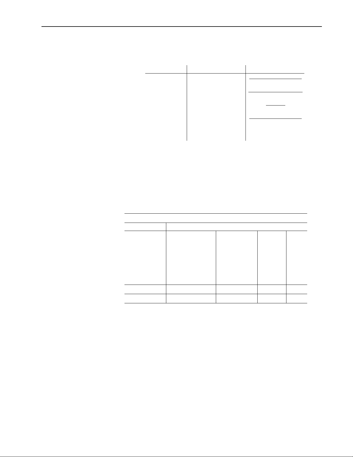
Chapter Title Contents
Describes the purpose, background, and scope
Preface
1 Safety Lists safety information regarding the Compact.
2 Introduction Provides a feature overview of the Compact.
3 Technical Overview Provides a technical overview of the Compact.
4
5
6
7 Troubleshooting
Appendix A Cable Information
Installation and
Hookup
Understanding the
IMC-S23x Setup
Setting Up your
Compact
of this manual. Also specifies the audience for
whom this manual is intended.
Provides information that allows you to install and
hook up your Compact.
Provides information that allows you to
understand the setup procedures for the
Compact.
Provides setup procedures for the Compact.
Explains how to interpret and correct problems
with your Compact.
Provides information about the cables used with
the Compact.
Publication 999-122 - January 1997
Page 13

Preface P-3
Related Documentation
The following documents contain additional information concerning
related Allen-Bradley products. To obtain a copy, contact your local
Allen-Bradley office or distributor.
For Read This Document Document Number
A description and specifications for the Compact Compact Motion Controller Product Data 4100-2.3
A user guide for GML programming to be used with the Compact. GML Programming Manual GML-DOC-S
An overview of the Flex I/O products Flex I/O Product Profile 1794-1.14
Specifications for the Flex I/O products Flex I/O Product Data 1794-2.1
Published by the
An article on wire sizes and types for grounding electrical equipment National Electrical Code
A complete listing of current Allen-Bradley documentation, including
ordering instructions. Also indicates whether the documents are
available on CD-ROM or in multi-languages
A glossary of industrial automation terms and abbreviations Allen-Bradley Industrial Automation Glossary AG-7.1
Schematics related to the Compact. Schematics 4100-5.0.01
Allen-Bradley Publication Index SD499
National Fire
Protection Association
of Boston, MA.
Compact Prod uc t
Receiving and Storage
Responsibility
Allen-Bradle y Support
You, the customer, are responsible for thoroughly inspecting the
equipment before accepting the shipment from the freight company.
Check the item(s) you r eceive aga inst your purchase or der. If any items
are obviously damaged, it is your responsibility to refuse delivery until
the freight agent ha s n oted the damage on the freight bil l. Shoul d you
discover an y concealed damage during unpacking, you are responsible
for notifying t he freight agent. Lea ve t he shipping container i ntact and
request that the freight agent make a vi sual inspection of the equipment.
Leave the pro duct in its shi pping contai ner prior to instal lation. If you
are not going to use the equipment for a period of time, store it:
in a clean, dry location
•
within an ambient temperat ure range of -40 to 70 ° C (-40 to 158° F)
•
within a relative humidity range of 5% to 95%, non-condensing
•
in an area where it cannot be exposed to a corrosive atmosphere
•
in a non-construction area
•
Allen-Bradley offers support services worldwide, with over 75
Sales/Support Of fices, 512 auth orized Distrib utors and 260 authorized
Systems Integrators located throughout the United States alone, plus
Allen-Bradley representatives in every major country in the world.
Publication 999-122 - January 1997
Page 14

P-4 Preface
Local Product Support
Contact your local Allen-Bradley representative for:
sales and order support
•
product technical training
•
warranty support
•
support service agreemen ts
•
Technical Product Assistance
If you need to contact Allen-Bradley for technical assistance, please
review the information in the
your local Allen-Bradley representative. For the quickest possible
response, we recommend that you have the catalog numbers of your
products av ailable when you call . The Rockwell Automation T echnical
Support number is (
603) 443-5419
Troubleshooting
.
chapter first. Then call
Publication 999-122 - January 1997
Page 15
Safety
Chapter
1
Read This Manual
Read and understand this instruction manual. It pr ovides the nece ssary
information to allo w you to install, connect, and se t up your IMCñS/23x
for safe, reliable operation.
ATTENTION: DANGEROUS MACHINERY!
Operation and maintenance of automatic equipment
!
!
involves potential hazards. Control Operators, Setup
Personnel, and Programmers should each take
precautions to avoid injury.
Injury and entanglement may occur if hands and limbs
come in contact wit h moving machinery . KEEP HANDS
CLEAR of dangerous moving machinery. Loose fitting
clothing or ties ca n become entangled in the machinery.
These items should not be worn while operating,
servicing, or programming the machine.
ATTENTION: HIGH VOLTAGES!
Electric shock can ki ll. Be sure the con troller is safely
installed in accordance with the Installation and
Hookup Section of this manual. Avoid contact with
electrical wires and cabling while power is on. The
electrical cabinet should be opened only by trained
service personnel.
ATTENTION: STATIC CONTROL!
The internal modules of the IMC S Class Compact motion
!
controller contain staticñsensitive electronic
components. Remove and handle the internal modules
only at a staticñsafeguarded work area. Failure to do so
may result in a dra st ica lly shortened life of your moti on
controller.
A disposable wristñstrap for grounding yourself is
included with this product. Please follow the directions
for use of this strap when removing and handling the
motion controller s internal modules.
Publication 999-122 - January 1997
Page 16

1-2 Safety
Publication 999-122 - January 1997
Page 17

Introduction
Chapter
2
IMC-S/23x Description
The IMC-S/23x is a compact, rugged, microprocessor-based two- or
four-axis servo motion controller. By including the logic and field
power supplies, t he IMC-S/23x pro vides a comp letely programmabl e,
stand-alone motion and logic controller suitable for a wide variety of
industrial applications.
The IMC-S/23x, in conjunction with external drive systems and
feedback encoders, provides two or four axes of closed-loop
point-to-point positioning with profile (trapezoidal, parabolic, or
S-curve), velocity, acceleration, and deceleration control as well as
multi-axis linear, circular, or helical interpolation. The electronic
gearing feature allows any axis to be slaved to another at a
programmable ratio. The electronic cam feature allows coordinated
motion profiles which are functions of ti me or position of another axis.
Sophisticated phase shift, auto-registration, and auto-correction
capabilities allow many complex motions and synchronizations to be
easily programmed. General-purpose discrete I/O, analog inputs,
analog outputs, et c. are provided by dire ct connection of Allen-Bradl ey
Flex I/O modules. Up to eight Fle x I/O modules–pro viding a total of
128 discrete I/O poi nts –may be connected directly to the IMC-S/23x.
Analog inputs and outputs can be substituted for discrete I/O blocks
for increased I/O flexibility.
Application programming of the IMC-S/23x for any application is
accomplished with GML, the exclusive Graphical Motion Control
Language from Allen-Bradley. Using GML, over 100 different
commands are available to completely customize operation of the
IMC-S/23x for your specific application. Complete application
programs are downloaded to the IMC-S/23x via a field-configurable
RS-232C or RS-422 port where they are store d in non-volati le memory
(write-protected battery-backed RAM).
A prompted, English-language machine setup procedure, complete
hookup diagnostics, an d improved Automatic Servo Setup routines for
self-tuning the se rvo paramet ers make setti ng up the IMC-S/23x q uick
and easy.
Publication 999-122 - January 1997
Page 18

2-2 Introduction
Features
A dedicated serial port–which can be field-configured for RS-232,
RS-422, or Allen-Bradley DH-485 communications–is prov ided for the
man-machine interface (MMI). Connection of the MMI device is via
an AT-compatible DB-9 connector (RS-232 or RS-422) or RJ-45
connector (DH-485), both locate d on the f ront pan el. If DH-485 is not
used, a multi-unit addressing scheme (Multidrop) allows up to eight
IMC-S/23x motion controll ers to share a single RS-422 communication
channel in sophisticated multi-axis systems. The address of each unit
is set by a recessed front panel rotary switch.
The Remote I/O option allows the IMC-S/23x to communicate directly
with an A-B PLC® via Remote I/O using both discrete and block
transfers. The AxisLink option allows axes on other IMC S Class
controllers or ALECs (AxisLink Encoder Converter modules) to be
used as master axes for electronic gearing and cams. This ability
provides real-time coordination for distributed, multi-axis systems in
electronic gearing, cam, lineshaft, and synchronization applications.
Powerful graphical software development system (GML) makes
•
application programming easy and fun.
State-of-the-art Intel i960 RISC microprocessor.
•
Fast application program execution (most commands executed in
•
less than 1 µs) ensures highest machine performance and
productivity.
Completely digital–no potentiometers or other adjustments
•
required; wi ll not drift with time temperature or humidity.
Multitasking operating sy stem allows simult aneous execution of up
•
to 10 tasks for efficient utilization.
Electronic gearing for synchronization of any axis to another at a
•
programmable ratio. Ratio may be specified as a floating-point
number of integer fraction (1/3, 3/10 etc.).
Electronic cam for co ordinated motion profil es on one or more axes.
•
Profiles may be position versus time or slave axis position versus
master axi s position.
Sophistic ated phase shift and advance/r etard capabilities for
•
electronic gears and cams allows complex motions to be easily
programmed.
Auto-registr ation and auto-corr ection make high-spe ed registratio n
•
applications easy.
Exclusive Imaginary Axi s provi des addit ional command-onl y axis
•
for precise generat ion of master motion in master-sl ave applications
or correction moves in registration and synchronization
applications.
Concurrent, independent, or synchronous motion on all axes.
•
Interpolated motion on up to three axes.
Publication 999-122 - January 1997
Page 19

Introduction 2-3
Wide position, speed, acceleration, and deceleration ranges for
•
precise control.
Separately programmable acceleration and deceleration rates for
•
maximum versatility.
Trapezoidal, parabolic, and S-curve velocity profiles.
•
Rotary mode with electronic unwind allows unlimited position
•
range for rotary axes.
Merge motion functi on allows seamless trans ition between all types
•
of motion.
Most motion parameter s (including master axis for electr onic gears
•
and cams) can be changed on-the-fly with no delays.
Powerful floa ting-poi nt math ca pabilitie s includi ng trans cendental
•
functions (sin, cos, log, etc.).
Sophisticated Nested Digital Servo Control Loop with automatic
•
servo setup for quick and easy servo tuning.
Isolation of all e xternal connections fr om the microproces sor logic
•
for reliable performance.
4 MHz maximum feedback count rate allo ws high s peed opera tion
•
without sacrificing resolution.
Encoder loss detection protects operators and machinery from
•
damage in the event of encoder feedback failure.
Isolated 16-bit DA Cs for smooth motion. Software offset correction
•
eliminates drift with analog servo drives.
Field-configurable servo outputs allow independent selection of
•
±10V or ±150 µΑ signal format for each axis.
Programmable position lock and posit ion error toler ances for serv o
•
fault protection.
Programmable directional software travel limits for enhanced
•
overtravel protection.
Vel ocity Feedforward to reduce following error.
•
Four optically isolated limit switch inputs for a home switch,
•
positive and negative overtravel switches, and a drive fault signal
for each axis.
Relay-contact drive enable output for each axis.
•
Optically isolated high-speed position registration input for each
•
axis for position synchronization and registration applications.
CPU Watchdog with front-panel LED indicator for fail-safe
•
protection.
Publication 999-122 - January 1997
Page 20
2-4 Introduction
AxisLink option allows real-time axis coordination between
•
controllers for distributed, multi-axis systems.
Non-volatile storage (write-locked battery-backed RAM) of
•
application program, setup parameter and default variable values.
Memory Lock keyswitch on front panel prevents accidental or
•
unauthorized changes to application program, default setup
parameters, and default variable values.
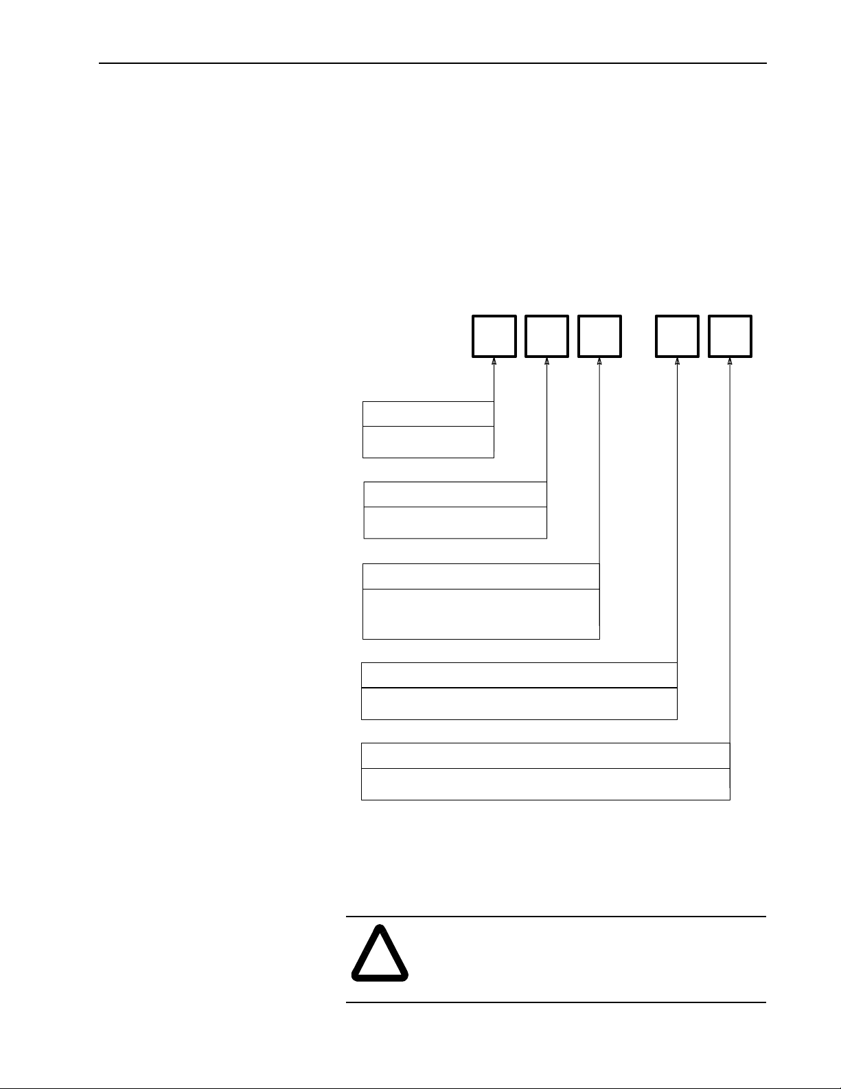
Model Numbering System
The IMC-S/23x is available as a two- or four-axis motion controller
with optional Remote I /O Adapter and AxisLin k. The complete model
number is specified as shown below:
IMC-S/
Platform
2 = Stand Alone
Packaging
3 = Compact Package
Number of Axes
2 =Two Axes
4 = Four Axes
2
3
-
Pre-Engineered Cable
Assemblies
Remote I/O Option
R = Remote I/O Adapter
AxisLink Option
L = AxisLink Multi-Axis Synchronization Link
Pre-engineered cable assemblie s are used for connec ting the Fl ex I/ O,
servo amplifiers, feedback devices, axis-specific (dedicated) I/O, and
the CPU watchdog. The table below shows the available cable
assemblies.
ATTENTION:
connections to the IMC-S/23x while the power is on!
!
Doing so risks damage to the IMC-S/23x, external
components, and your health!
Do not attempt to make any electrical
Publication 999-122 - January 1997
Page 21
IMC S/23x Pre-Engineered Cable Assemblies
Catalog Number Used to Connect. . . Length
(ft) (m)
4100-CCF1
4100-CCF3
4100-CCS15F
4100-CCAQB
4100-CCA15F
4100-CCW15F
4100-RCS3T
or
Flex I/O
Servo and Feedback
1391B-ES or 1391-DES
Dedicated Discrete I/O
CPU Watchdog
REC Interface
10.3
31
15 4.5
-15 4.5
15 4.5
31
Introduction 2-5
Number
Required
1 per S Class
1 per Axis
1 per Axis
1 per Axis
1 per S Class
1 per Axis
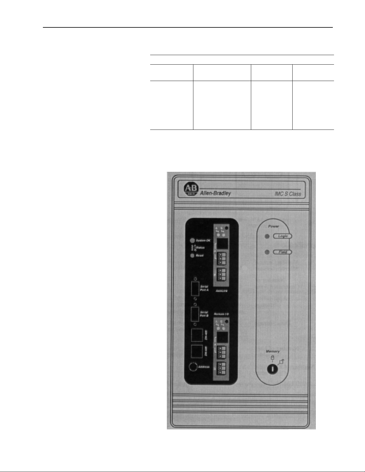
Mechanical Specifications
Front Panel Layout
(IMC-S/23x-RL model shown.)
Publication 999-122 - January 1997
Page 22
2-6 Introduction
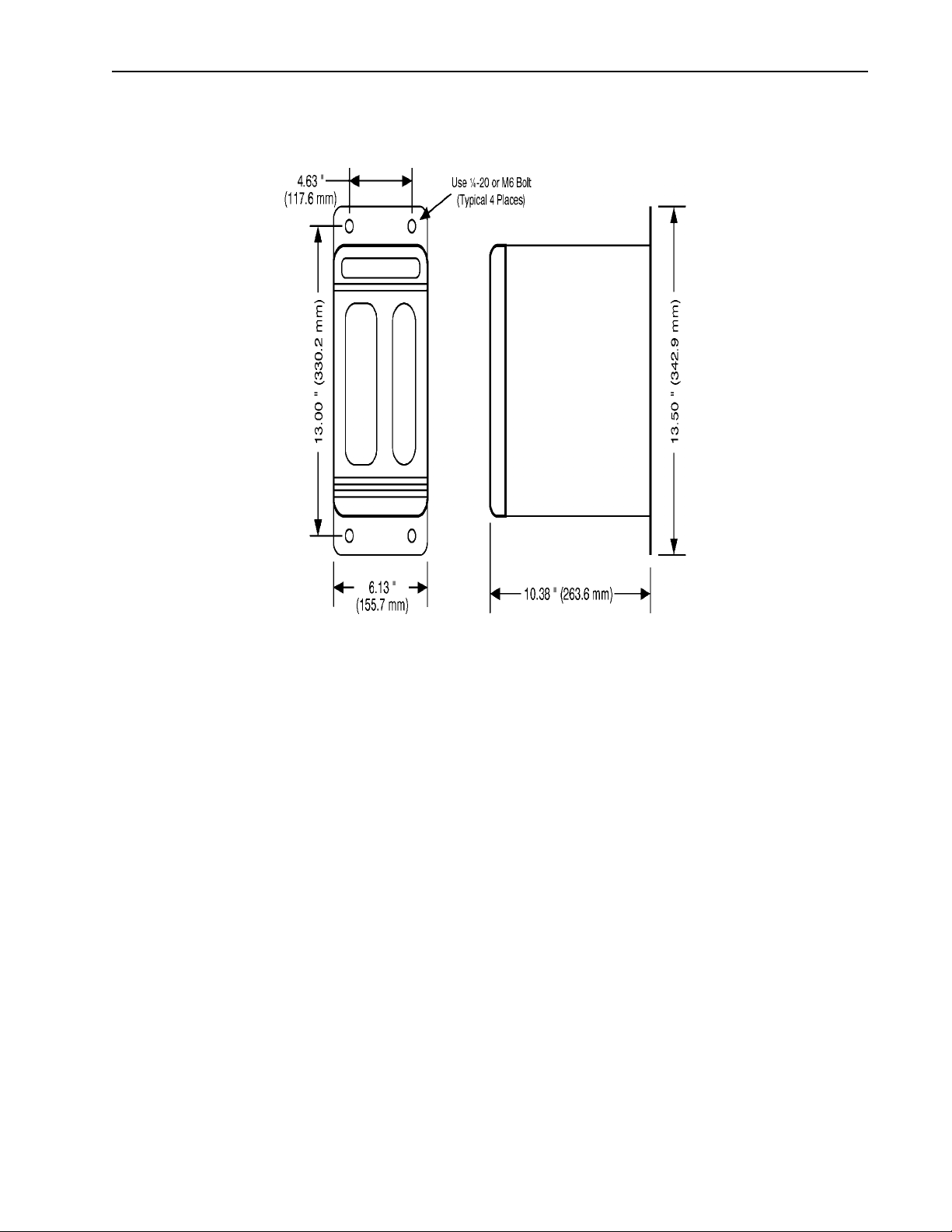
Mounting and Clearance Dimensions
General Specifications
Motion Control
Microprocessor
Number of
Controlled Axes
Application
Storage
Data Storage
Number of User
Variables
Number of Electronic
Cam Poi n ts
Intel 80960SB @ 16 MHz.
2 (Axis 0 and Axis 1) IMC-S/232...models.
4 (Axis 0, 1, 2, and 3) IMC-S/234...models.
Write-lockable batt ery-backed RAM (Ran dom-Access Memory) with 10
year (minimum) battery life for application program (32K) and setup
parameter values.
Write-lockable batt ery-backed RAM (Ran dom-Access Memory) with 10
year (minimum) battery life for cam table and default user variable values.
2,000 user-definable; values stored as 64-bit floating-point numbers.
26,000 total.
Publication 999-122 - January 1997
Page 23

Envir onmental Specifications
Storage
Temperature -40°C to 70°C (-40°F to 158°F).
Operating
Temperature 0°C to 50°C (32°F to 122°F).
Maximum
Humidity 95% non-condensing.
Electrical Specifications
AC Power Input 90 - 132 or 175 - 264 Volts AC,
AC Fuse 3A Dual Element Time Delay (Slow Blow) 1/4 x 11/4
I/O Power Input 18 - 36V DC,
I/O Fuse 3A Dual Element Time Delay (Slow Blow) 1/4 x 11/4
Introduction 2-7
47 - 63 Hz,
3 Amperes maximum.
3A maximum (24V nominal).
Encoder Input Specifications
Number of
Encoder Inputs
Type of
Encoder Input
Encoder
Interface IC AM26LS32 or equivalent.
Compatible
Encoder Types
Decode Modes 4X Quadrature, Step/Direction, Count Up/Count Down.
Maximum Encoder
Frequency
Input
Impedance 7 kΩ minimum (each input).
Encoder
Power
2 (Axis 0 and Axis 1) IMC-S/232...models.
4 (Axis 0, 1, 2, and 3) IMC-S/234...models.
Incremental AB quadrature; optically isolated, differential with marker
channel.
Differential, TTL-Level (5V DC) line driver outputs, with or without
marker; including the following Allen-Bradley devices:
845F-SJxZ14-xxYx...
845F-SJxZ24-xxYx...
845H-SJxx14xxYx...
845H-SJxx24xxYx...
845K-SAxZ14-xxY3
845K-SAxZ24-xxY3
845P-SHC14-xx3
845T-xx12Exx...
845T-xx13Exx...
845T-xx42Exx...
845T-xx43Exx...
4,000,000 counts per second (4 MHz). This is equivalent to a channel
frequency of 1 MHz in 4X quadrature decode mode.
5 or 12 Volts DC at 1 Ampere (tot al) a v a ilable f rom IMC-S/23x . Voltage
selection by internal sw itch.
Publication 999-122 - January 1997
Page 24

2-8 Introduction
Servo Output Specifications
Number of
Servo Drive Outputs
Type of Output Isolated analog voltage or current; individually field-configurable via
Output Range ±10 Volts DC or ±150 µA (minimum).
Resolution 16 bits, 305 µV or 4.58 µA per bit.
Output Impedance 220Ω resistive for voltage output; 56Ω maximum load impedance for
Output Offset ±80 µV maximum. Compensated to 0 volts via soft ware setup pr ocedure.
Dedicated Discrete I/O
Specifications
Number of
Dedicated Discrete
Inputs
Dedicated
Discrete Input
Functions
Input Type Optically isolated.
Operating
Voltage
Input ON
Current
Impedance
Input Response
Number of
Dedicated
Discrete Outputs
Dedicated Discrete
Output Function
Output Type Normally-open relay contacts (Drive Enable);
Operating
Voltage
Output
Current
Input
Time
2 (Axis 0 and Axis 1) IMC-S/232...models.
4 (Axis 0, 1, 2, and 3) IMC-S/234...models.
internal switch for each axis.
current output.
10 (5 each for Axis 0 and 1) IMC-S/232...models.
20 (5 each for Axis 0, 1, 2, and 3) IMC-S/234...models
Home Limit Switch,
Positive Overtravel Limit S witch,
Negative Overtravel Limit Switch,
Drive (Amplifier) Fault,
Position Registration.
24 Volts DC nominal; 28V DC maximum.
24 Volts DC nominal; 28V DC maximum or 5 Volts DC nominal;
10V DC maximum for position registration inputs.
12 µΑ per input (nominal);
2.5 µΑ for position registration inputs.
2 kΩ (resistive) per input;
8.8 kΩ (resistive) for 24V position registration inputs.
5 µs maximum;
1 µs maximum for pos ition registration i nputs.
4 (2 each for Axis 0 and 1)IMC-S/232...models.
8 (2 each for Axis 0, 1, 2, and 3)IMC-S/234...models.
Drive (Amplifier) Enable.
Absolute Position Strobe.
Optically isolated, floating, solid-state relay (Position Strobe).
0.010 - 40 Volts DC; 24V DC nominal for drive enable outputs,
5.10± 0.10 Volts DC for position strobe outputs.
1 Ampere per output maximum for drive enable outputs;
10 µΑ per output maximum for position strobe outputs.
Publication 999-122 - January 1997
Page 25

Serial I/O Specifications
Number of
Serial Channels 2 (Serial Port A and Serial Port B).
Channel Type Optically isolated RS-232C or RS-422; each channel individually
Information Code ASCII (American Standard Code for Info rmation Interchange).
Baud Rate User-selectable up to 128k Baud (RS-422).
Number of
Start Bits 1.
Number of
Stop Bits 1.
Word Length 8 bits total; 7 data bits plus 1 parity bit.
Parity Space parity transmitte d;
Duplex Full or half (user-selectable).
Data
Synchronization XON (Control-Q)/XOFF (Control-S).
Front-Panel
Connectors IBM-PC /AT compatible 9-pin D-type female.
RS-422
Termination User-selectable 220Ω resistor via internal switch.
Introduction 2-9
configurable via internal s witch.
User-selectable up to 115.2k Baud (RS-232C).
Receive parity ignored (may be Mark, Space, Even, or Odd).
DH-485 Specifications
Number of
DH-485 Channels 1; replaces Serial port B when used.
Channel Type Optically isolated half-duplex RS-485.
Baud Rate 9,600 or 19.2k Baud (user-selectable).
Front-Panel
Connectors Two RJ-45 jacks (+24V is not provided).
RS-485
Termination User-selectable 220Ω resistor via internal switch.
Node Address User-selectable between 0 and 31 inclusive.
Node Type Token-passing master.
Accessible Data
Files
1 Binary file (B3) for up to 16,384 bits
1 Integer file (N7) for up to 1,024 16-bit values
1 Floating-point file (F8) for up to 512 32-bit values
1 ASCII string file (A) for up to 2, 048 characters
9 user-configurable files; each can be individually configured as any of
the above types or as a BCD file for floating point simulation (required
for certain A-B MMI devices).
Publication 999-122 - January 1997
Page 26

2-10 Introduction
Flex I/O Compatibility
Specifications
Maximum Number of
Flex I/O Modules 8.
Compatible
Modules
S Class Interface Direct-no 1794-ASB or other adapter required.
Servo Performance
Specifications
Servo Loop
Sample and Update
Maximum Feedback
Frequency 4 MHz (4,000,000 feedback counts per second).
Absolute
Position Range
Absolute Position
Resolution
Speed Range 0.00001 feedback counts per servo update to 4,000,000 feedbac k counts
Speed Resolution 15 position unit digits or
Acceleration/
Deceleration Range
Acceleration/Deceleration
Resolution
Electronic Gearing
Gear Ratio Range 0.00001:1 to 9.99999:1 (slave counts : master counts).
Electronic Gearing
Gear Ratio Resolution 8 position unit digits or 32 feedback count bits.
Servo Gain Resolution 32 bit floating point.
Servo Output Limit
Servo Output Limit
Resolution 305 µ (voltage output); 4.58µΑ (current output).
1794-IB16 16 24V DC Discrete Inputs
1794-IA8 8 115V AC Discrete Inputs
1794-IE8 8 Current/Voltage Analog Inputs
1794-OB16 16 24V DC Discrete Outputs
1794-OA8 8 115V AC Discrete Outputs
1794-OE4 4 Current/Voltage Analog Outputs
1794-IE4XOE2 4 Current/Voltage Analog Inputs
2 Current/Voltage Analog Outputs
Rate 250 Hz to 2 kHz for each of 2 or 4 axes.
± 1,000,000,000 feedback counts for Linear AxisAxi s:Lin earli near ax es ;
R for rotary a xes.
15 position unit digits or
32 feedback count bits, whichever is less.
per second.
15 feedback count bits, whichever is less.
0.00001 feedback counts per servo update2 to 4,000,000,000 feedback
counts per second2.
15 position unit digits or
15 feedback count bits, whichever is less.
Range 0 to 100%.
Publication 999-122 - January 1997
Page 27
Servo Gain Units
IMC-S/23x Servo Gain Units
Gain Description Units
P
I
V
F
Proportional Gain
Integral Gain
Velocity Gain
Feedforward Gain
Deadband Compensation
Offset Compensation
Introduction 2-11
Counts per Millisecond
Count of Error
Counts per Millisec ond2
Count of Error
Millivol ts
Count per Mi llisecond
Counts per Millisecond
Count per Mi llisecond
Volts
Volts
Remote I/O Adapter
Specifications
Baud Rate
Rack Address
Rack Width
I/O Group Address
IMC-S/23x-R and IMC-S/23x-RL models only.
57.6K, 115.2K or 230.4K (User-selectable).
User-selectable between 0 and 31 decimal.
User-selectab le in quarter-rack increment s (1/4, 1/2, 3/4, Full).
User selectable as shown below:
IMC-S/23x Remote I/O Adapter Addressing
Type of Transfer I/O Group
Block
Discrete
Discrete
Discrete
Discrete
Discrete
Discrete
Discrete
Starting I/O Group 0246 024 02 0
Rack Width
0246
1357
1/4 1/2 3/4 Full
024
135
246
357
02
13
24
35
46
57
0
1
2
3
4
5
6
7
Publication 999-122 - January 1997
Page 28

2-12 Introduction
Number of
Discrete I/O Bits
12 dedicated inputs,
12 dedicated outputs,
User-defined as shown below:
IMC-S/23x Remote I/O Adapter
Number of User-Defined Discrete I/O Bits
Rack Width Inputs Outputs
1/4
1/2
3/4
Full
Maximum Block
Transf er Length 64 words (128 bytes).
Block Transfer
Data Types
User Variable values,
Axis Data Parameter value,
Axis Data Bit state,
Master Cam Posi tion Point values,
Master Cam Time Point values,
Slave Cam Position Point values,
Axis or System Variable value.
Block Transfer
Data Formats
32-bit (double-word) 2s complement integer,
16-bit (single-word) 2s complement integer,
32-bit (8-digit) signed BCD,
32-bit IEEE floating-point,
Word-swapped 32-bit (double-word) 2s complement integer,
Word-swapped 32-bit (8-digit) signed BCD,
Word-swapped 32-bit IEEE floating-point.
36
68
100
4
4
36
68
100
Publication 999-122 - January 1997
Page 29

Introduction 2-13
AxisLink Specifications
Baud Rate Standard and extended
Cable Type Standard and extended
Cable Length Standard and extended
Number of
Motion Controll ers
Addressing Standard and extended
Number of Virtual
Master Axes
Type of Virtual
Master Axes
Slave Axes Standard and extended
IMC-S/23x-L and IMC-S/23x-RL models only.
1 megabit per second.
node configurations
Extended length
500 kilobit per second.
configuration
Allen-Bradley 1770-CD RIO cable (Belden 9463 or
node configurations
Extended length
equivalent).
Belden 9182, Carol C8014 or equivalent.
configuration
25 meters (82 feet) maximum total. Minimum of 1
node configurations
Extended length
configuration
Standard and extended
meter (3 feet) between controllers.
125 meters (410 feet) maximum total. Minimum of 1
meter (3 feet) between controllers.
8 maximum for a total of 32 possible axes.
length configurations
Extended node
16 maximum for a total of 64 possible axes.
configuration
User-selectable address via rotary selector switch on
length configurations
Extended node
front panel.
User-selectable address via GML.
configuration
Standard configuration 4 maximum total; 1 per motion controller maximum.
Any axis on any motion controller can be a virtual
master axis to any ot her motion controller . Each motion
controller can de fine a total of tw o separate axes on an y
other motion control lers as virtual master axes, b ut only
one can be active at any time. A tot al of f our di fferent
axes can be active as virtual master axes at any time.
Extended length and
extended node
configurations
2 maximum total; 1 per motion controller maximum.
Any axis on any motion controller can be a virtual
master axis to any ot her motion controller . Each motion
controller can de fine a total of tw o separate axes on an y
other motion control lers as virtual master axes, b ut only
one can be active at any time. A total of two different
axes can be active as virtual master axes at any time.
All configurations 2: Command and Actual. Each virtual mast er axis may
be defined to report its command or actual position.
31 maximum total per virtual master axis (3 local + 4
length configurations
Extended node
configuration
x 7 other motion controllers = 31).
63 maximum total per virtual master axis (3 local + 4
x 15 other motion controllers = 63).
Publication 999-122 - January 1997
Page 30

2-14 Introduction
Number of
Discrete I/O
Discrete I/O
Response
All configurations 112 inputs maximum total and 16 user-definable
outputs per motion controller. Any motion controller
can read the 16 discrete outputs of any other motion
controller, giving a maximum total of 7 x 16 = 112
discrete inputs per motion controller. For extended
node configuration, discrete I/O can still only be
obtained from a maximum of 7 other controllers (112
inputs maximum total), n ot from all 15 other controllers
available in a 16 node maximum extended node
configuration.
All configurations ≤1 millisecond.
Publication 999-122 - January 1997
Page 31

Technical Overview
Chapter
3
Digital Control Loop
Each axis of the IMC-S/23x utilizes a powerful Nested Digital Servo
Control Loop to provide servo positioning control and compensation
of a servo actua tor. The servo actuator can be a DC motor, a brushless
DC motor, an AC motor (with the appropriate drive electronics), or a
hydraulic cylinder or motor.
The Nested Digital Serv o Control Lo op utilizes s tate-of-the- art digital
hardware and sof tware to perfo rm the func tions nec essary to e stablis h
a closed l oop servo system. The only external elements neede d to
complete the servo loop are:
Actuator (Brushless DC Motor, Hydraulic Cylinder, etc.)
•
Servo Amplifier for Actuator
•
Digital Incremental Encoder (Quadrature type)
•
The digital approach t o motion cont rol has numerous adv antages o v er
conventional analog servo control techniques. Digital feedback
eliminate s the need for potentiometers in the control loop with their
associated adjustmen t labor and dr ift. Furthe rmore, the Nested Di gital
Servo Loop is microprocessor-based. Microprocessor design reduces
the system parts count, increases system reliability, and greatly
increases the flexibility of the control.
The Nested Digital Servo Loop synthesizes a velocity (rate) loop as
well as the required position loop in software using only the position
information provided by the encoder (or other feedback device). No
analog tachometer is required to provide complete stabilization and
positioning control of the motor and load. In addition, velocity
feedforward is provided to reduce the intrinsic following error of the
position loop when the motor is moving.
Publication 999-122 - Janua ry 1997
Page 32

3-2 Technical Overview
A functional block diagram of the Nested Digital Servo Loop is shown
below. The following sections discuss, in detail, each block in this
diagram.
Encoders
The IMC-S/23x interfaces to rotary or linear quadrature-type
incremental encoders to provide both position and velocity feedback.
The most common type of such encoders are optical; they utilize a light
source and an alternately clear and opaque disc or scale to generate
their output.
When operating at a f ixed speed, quadrat ure-type incremental enco ders
generate two squar e wave outputs , usually referred to as Channel A and
Channel B, which are approx imately 90° out of phase with one a nother.
Proper phasing of these two channels can be checked by driving the
encoder at a fixed speed and displaying the two encoder outputs on a
dual channel oscilloscope.
Encoders are available with a variety of different output driver
configurations. The IMC-S/23x interfaces directly to differential line
driver encoders providing TTL (5V) level signals. In addition, the
encoder inputs ar e optically isolated and po wered from a separate po wer
supply contained withi n the IMC-S/23x. Encoder loss circuitry dete cts
when any of the encoder connections have broken.
Publication 999-122 - Janua ry 1997
Page 33

Technical Overview 3-3
Often a third output channel is available from the encoder. This
so-called "marker" output is also known as Channel Z, 0, or C. The
marker output from an encoder is a pulse that occurs at one specific
point on the encoder disc (rotary encoders) or slide (linear encoders).
Therefore, the marker may be used to establish a precise absolute
position reference. Note that for rotary encoders, the marker provides
a position referenc e within one revolution of the encoder. F or multi-turn
applications, othe r means must be us ed in conjunct ion with the mark er
pulse to determine the absolute position. The IMC-S/23x can interface
to encoders with marker pulse outputs of either active-high or
active-low polarity.
Encoder Counter
The encoder counter circuitry is identical for all axes and consists of
optically-isolated AM26LS32 input buffers, programmable decode
logic, and 16-bit encoder counters contained within the CX2216.
Once buffered and isolated, the two TTL-level encoder signals
(Channel A and B) are c onnecte d to the CX22 16 which de codes them
using 4X quadrat ure logic (4 cou nts per e ncoder lin e). Afte r decoding,
the count signals are sent to the encod er counter in the CX2216 , which
keeps a record of the number of counts and the direction of encoder
motion. The IMC-S/23x software extends the encoder counters to 32
bits giving a total position range of ±1,000,000,000 encoder counts.
A quadrature type enc oder generates four counts for every line on the
encoder disc or s lide. The sequenc e in whi ch th e co unts a re gen era ted
is determined by the direction that the encoder is moving, and the
encoder counter increments or decrements accordingly.
The maximum encoder rate for any digital control is determined by
many factors, i ncluding t he sample r ate of the c ontrol lo op, the siz e of
the encoder counters , and pulse ra te limitati ons of the digit al circuit ry .
The maximum encoder count rate, or
encoder bandwidth
, for the
IMC-S/23x , is 4.0 Megahert z.
Every servo sample period, the microprocessor reads the encoder
counter for each axis and computes a count increment by subtracting
the previ ous counter value from the present counter value . Thi s c ount
increment repres ents the distanc e the axis has tr aveled i n the precedin g
millisecond. This v alue is then us ed to update the 32- bit actual position.
Publication 999-122 - Janua ry 1997
Page 34

3-4 Technical Overview
Software Feedback
Calculations
Every servo sample period, the IMC-S/23x microprocessor also does
a complete position feedback calculation for each axis by first
computing the dif ference between the actual positi on and the command
position. This quantity is called the Position Error. The intent of every
closed loop position se rvo syst em is to driv e this position error to zero.
T o accompl ish this, the position erro r is mult iplied by a pro grammable
P (Proportional) Gain term and used to generate a velocity command.
In addition, when the axis is not moving, po sition error i s accumulated
(integrated) and multiplied by the I (Integral) Gain term and added into
the velocity command. This allows the IMC-S/23x to compensate for
static disturbances that would otherwise keep the position error from
becoming zero. Such static disturbances include static friction
(so-called Sticktion) and gravity effects on vertical axes.
Integral Gain is also effective in reducing the tracking erro r between
the master and slave axis when the electronic gearing feature is used.
The integral term is deactivated, however, when performing
commande d motion (moves an d jogs) to improve servo stability and
decrease overshoot.
To create a stable position servo loop without using an analog
tachometer, damping is provided by synthesizing a tachometer in
software. This is accomplished by calculating the rate of change of
encoder position to generate the actual velocity. The actual velocity is
compared to (subtracted from) the command velocity to generate the
velocity error. This velocity error is then multiplied by the
programmable V (Velocity) Gain and used to dri ve the mot or to reduce
the velocity error (an d thus t he positi on error al so) to zer o. W ith serv o
drive s incorporatin g a true tachomet er loop, the so ftware v elocity loop
is disabled.
After being mult iplied by the V gai n, the veloci ty error is range l imited
and then se nt out to a 16-bit DAC (Digital-to-Anal og Converter to
generate the ±10 volt or ±150 mA signal for use by the drives.
In use, the servo output ranges between ±10 volts or ±150 mA,
depending on the settin g of the drive out put type switch. The maximum
output can also be cla mped to less than the abo ve full scale v alues. This
servo output limit is fully programmable.
In addition, deadband compensation is provided to compensate for
friction effects when using current-loop servo amplifiers. Deadband
compensation adds a programmable valu e to the magnitude of t he servo
output signal (i.e. when the velocity error is positive, the DB
compensation value is added, and when the velocity error is negative,
the DB compensation value i s subtracted) .
Publication 999-122 - Janua ry 1997
Page 35

Technical Overview 3-5
Finally, drive offset compensation is provided to allow compensating
for the inevi table offset and drift in anal og servo amplifiers. Dri ve offset
compensation adds a programmable valu e to the magnitude of t he servo
output signal.
Each of the gain terms me ntioned abo v e has a u nique influe nce on th e
closed loop dynamics of t he system. By adjust ing the P, I, and V gains,
it is easy to tailor the syst em dynamics to meet specific needs. The three
programmable control ga ins influence t he closed loop dynamics i n the
following wa y:
Servo Amplifiers and
Motors
Proportional Gain
Integral Gain
Vel ocity Gain
⇒
⇒
⇒
Elastic Stiffnes s
Static Disturbance Compensation
Damping
Each axis of the IM C-S/23x can inter face to a sta ndard serv o amplif ier
operating in current (torque) or velocity (tach) mode which accepts a
±10V DC command. Servo ampli fiers are availabl e from Allen-Bradley
as well as other manufactur ers to drive DC, brushless DC or AC motors
in a wide range of powers. The IMC-S/23x can also interface to
hydraulic serv o and proportional v alves which acce pt ±150 mA signals.
Publication 999-122 - Janua ry 1997
Page 36

3-6 Technical Overview
High Level Motion
Functions
Destination
Position
Because servo action forces the actual position to track the command
position, sophisticated indexing, jogging, and electronic gearing
functions are easily implemented through software control of the
command position. These high le vel motion functions are sho wn below
and explained in the following paragraphs.
Trapezoidal,
Backlash
Compensation
Parabolic,
S-Curve,
Indexed
Ramp Up/Ramp Down
Jogger
Time-Lock Cam
Master Axis
Command
Position
Master Axis
Actual Position
Time
Position-Lock Cam
Master Position
Electronic Gearing
M
Interpolator 0
Interpolator 1
S
Command
Position
Σ
Publication 999-122 - Janua ry 1997
Page 37

Technical Overview 3-7
Indexing and Jogging
The indexer moves the axis using either a trapezoidal, parabolic, or
S-Curve (controlled jerk) velocity profile. Axis velocity, acceleration,
and deceleration are completely programmable. The trapezoida l profile
is the most common type of mov e and resul ts in a smooth acc eleration
to the desired sp eed and a smooth deceleration to th e desired destination
position. Parabolic and S-curve profiles are provided for use where
minimum stress on the mechanics is more important than minimum
index time.
The jogger produces constant speed motion of the axis in either
direction. The v elocity and the acceleration ra te are programmable. The
indexer an d jogger also pro vide th e ability to cha nge speeds and inde x
positions while the axis is mo v ing . The jogger also allows changes in
the acceleration or deceleration ramp while jogging. Furthermore,
electronic gearing may be combined with ind ex and jog motion to create
complex motion profiles and synchronizations.
Backlash Compensation
Another high level motion function is Backlash Compensation. This
technique–called Unidirectional Approach–overcomes mechanical
backlash by alw ays approaching the dest ination position from the same
direction. When ap proaching the destinat ion position from the opp osite
direction, the axis moves past the destination position by a
programmable Backlash Offset, reverses, and then moves back to the
destination positi on. Since the axi s al ways approa ches th e desti nati on
position from the same direction, the mechanical backlash is always
taken up in the same direction ensuring accurate positioning.
Electronic Cam
The electronic cam f eature pr ovide s the IMC-S/ 23x with t he abilit y to
execute coordinated motion profiles. This is accomplished by
programming a table of position values which describe the desired
profile, and then e xec uting the tab le as required. Ele ctronic ca ms may
be defined in terms of axis pos ition(s) v ersus time (time-lo ck cams) or
position of the slave axis versus position of the master axis
(position-lock cams).
Electronic Gearing
Electronic gearing allo ws an y ax is to be progr ammed to t rack another
axis at a specif ied ratio. By con vention, the axis that is tracking i s called
the
the master axis is equi v alent to the inpu t shaft, a nd the s lav e axis t o the
output shaft in a mechanical transmission.
, while the axis that is bein g tracked is called the
slave
Publication 999-122 - Janua ry 1997
master
. Thus,
Page 38

3-8 Technical Overview
Electronic gearing is accomplished by first reading the master axis’
actual position an d computing the distance increment fro m the previous
reading. This increment is then multiplied by a programmable gear ratio
and added to the slave axis’ command position. In this way the slave
axis is forced to track the master axis according to the specified gear
ratio. The slave axis may be programmed to move in the same or the
opposite direction from the master axis.
Electronic gearing ratios may be specified as a number between
0.00001:1 and 9.99999:1 . Alt er nat el y, the gear ratio may be specified
as a pair of intege r values–a numera tor and denominator– r epresenting
the exact ratio of slave axis feedback counts to master axis feedback
counts. The ability to s pecify numerator/denominator gear rati os makes
it possible to perform electronic gearing using an irrational gear ratio
such as 1/3 with no accumulated error.
By combining the jog and electronic gearing capabilities of the
IMC-S/23x, the slav e axis may be smoothly accelerated and dec elerated
into and out of electronic gearing motion. This merged motion
capability is equivalent to a software clutch.
Velocity Feedforward
Interpolation
T wo independent interpolators for all axes allow any two or three axes
to be moved as a group along a linear , circular , or helical path. Motions
from the two interpolators may be combined with each other or with
other types of motio n. Motion segments may be blended to one another
to accomplish continuous path motion as long as they are tangent at
their intersection.
The IMC-S/23x is capable of pro viding velocity fe edforward to reduce
following error. Following error is the servo position error that is
present when the axis is moving at a commanded speed. Without
velocity fe edforward, a fo llowing err or necessary to pr oduce suff icient
output to drive the motor at the comman ded speed will always exist.
Many applicatio ns require that the following error be near zero over
the entire speed range of the motor . Velocity feedfor ward may be used
to satisfy this requirement.
Velocity feedforward is provided by pre-computing the command
velocity as the rate of change with respect to time of the command
position. The command velocity is then scaled by the F Gain
(Feedforward Gai n) and added to the v elocity command. By adjusti ng
the F Gain it is poss ib le to produce, from the feedforward term alone,
the required ve locity command to d riv e the motor at the de sired speed.
Thus, only a little position error is needed to " fine tune" the motor spe ed
and position.
Publication 999-122 - Janua ry 1997
Page 39

Technical Overview 3-9
Velocity feedforward is v ery usef ul in el ectroni c gearing a pplicat ions,
since no position error between the master and slave axes exists with
mechanical gears. Using velocity feedforward also allows the position
loop integrator (I Gain) to respond more quickly to changes in speed.
CPU Watchdog
Software Overtravel Limits
Serial Communication
The IMC-S/23x pro vides a CPU Watchdog that monitors the he alth of
the motion control microprocessor. In the event of a processor
malfunction or other f ault, the CPU watchdog is im mediately disabled.
T o reset the Watchdog, the IMC-S/23x must be reset, either by cy cling
power, or by pressing the Reset button on the front panel.
An LED labeled "System OK" is provided on the IMC-S/23x front
panel to visually monitor the state of the CPU watchdog. This green
LED is lit under normal operation, and goe s out when the watchdog is
deactivated. A relay driven by the CPU watchdog provides normally
open and normally closed contacts on the Watchdog connector for
wiring into the machine’s E-Stop string or other fail-safe circuit.
The IMC-S/23x can be configured to range check the command
position of each axi s to ensure that the axis is oper ating within its limits.
These software travel limit values are fully programmable. When an
overtravel condition occurs, the IMC-S/23x either disables the
feedback loop and disables the amplifier, or decelerates the axis to a
stop. In either case, further motion in the offending direction is
inhibited.
Serial communicat ion with the IMC-S/23x is v ia either an RS-232C or
RS-422 serial link to one of two ports. If configured for RS-232C,
operation up to 19.2K baud is possible, while ports configured for
RS-422 can operate at up to 128K baud. A PC/AT-compatible 9-pin
D-type connector is pr ovided for each serial po rt on the fron t panel. In
general, the GML software development system for application
programming is connected to serial port A while a serial operator
interface device or runtime display is connected to serial port B.
The IMC-S/23x can be configured to operate in Multidrop Mode
allowing up to eight con trols to share a single RS-422 communicati ons
link. This is ac complished by using two special non- echoed commands
to activate individual units to respond to commands issued by the
operator interf ace device or host computer . Each IMC-S/23x is assigned
its own uniq ue address via a recesse d front-panel rotary sel ector switch.
Publication 999-122 - Janua ry 1997
Page 40

3-10 Technical Overview
DH-485 Communication
Axis-Specific Discrete I/O
The IMC-S/23x communicates with other devices over DH-485 by
reading and writing data i nto and out of data file s. Data from local fil es
(in the motion controller) is transferred to and from remote files (in
other devices ). In the motion contr oller , up to 13 dif ferent local f iles of
five different types can be used. Each type of file contains a different
number of elements and is equivalent to a different SLC file type as
shown belo w.
IMC S Class DH-485 Local File Types
S Class
File Type
Binary
Integer
Floating
ASCII
BCD
Elements Element
W ords/Bits
16-bit Values
Floating Point Values
Characte rs
BDC Values
Numbers
0 - 1023
0 - 1023
0 - 511
0 - 2047
0 - 1023
Equivalent to
SLC File T y pe
B
N
F
A
D
Each axis of the IMC-S/23x has associated with it four
optically-isolated inputs which provide a direct interface for a home
switch, overtravel (positive and negative) switches, and a drive fault
signal (usually an output from the amplifier). In addition, a relaycontact drive enable output is provided for each axis to enable and
disable the amplifier under program control. The four discrete inputs
are completely de-bounced and can be connected directly to limit
switches which operate on 24V DC. Inputs can be from mechanical
limit switches, proximity switches, or PLC outputs.
Each axis of the IMC- S/23x can be individuall y programmed to operate
with or without t hese discre te inputs e nabled. If enabled, each discr ete
input can be individually programmed to operate with normally open
(NO) or normally closed (NC) limit switch contacts.
Home Limit Switch Input
Home limit switches are used in conjunction with two of the four
programmable homing sequences. When a homing sequence is
enabled, the IMC-S/23x executes it under program control. See the
Setup section of this manual fo r a complete de scription of the avai lable
homing sequences.
Overtravel Limit Switch Inputs
Overtravel limit switches can be used to enforce the mechanical safe
travel limits during machine operation. Assuming that the overtravel
function is enabled, the IMC-S/23x may be programmed to either
provide a status, disable the feedback loop, and deactivate the drive
enable output of the affected axis, or stop motion and decelerate the
axis to a stop when an overtravel limit switch is tripped.
Publication 999-122 - Janua ry 1997
Page 41

Technical Overview 3-11
Drive Fault Output
The driv e fault inputs may be connected to the fault outputs (if provided )
on the amplifiers for each axis. This al lows the IMC-S/23x to re act to
a fault in the amplifiers themselves . Lik e t he othe r disc re te inp uts, th e
drive fault input may be enabled and disabled from the application
program, and may be configured to operate with active-high or
active-low drive fault outputs. When a drive fault input is activated,
assuming the function is enabled, the IMC-S/23x stops all motion on
the particular a xis and de acti v ates t he approp riate dri v e enabl e output .
Drive Enable Output
The driv e enable outp ut for each axis al lows t he IMC-S/23x to di sable
the axis amplif iers in the e vent of a motion f ault. Since it uses a fl oating
normally-open rel ay contact, the dri ve enable outp ut can be connected
to amplifier s ha ving ei ther ac tive-high or acti v e -lo w ena ble o r disab le
inputs.
Status LEDs
Position Registration Inputs
Special, high-speed, optically-isolated inputs on the IMC-S/23x (one
per axis) provi de a direct interface for position registration s ensors. The
position registration inputs are unfiltered to minimize propagation
delay for speed-critical position registration applications and can be
directly connected to sensors (or enco der markers) oper ating on 5V or
24V DC.
When a position registration input is activated, assuming the position
registration feature is enabled, the current actual position of the axis is
immediately latched in hardware into a special registration latch. The
latched registration position is then available within the application
program for calculations.
Three general purp ose status LEDs are provided on the front panel of
the IMC-S/23x. Labeled St atus 0, 1, 2, thes e LEDs are used to indicate
the results of the power-up diagnostics performed whenever power is
applied to the IMC-S/23x. If the IMC-S/23x passes its power-up
diagnostics, all th ree status LEDs are turn ed off and the CPU w atchdog
LED (System OK) is turned on. At this point, the three status LEDs
may be used by the application program for any desired purpose.
If all three status LEDs are not off after power -up, the IMC-S/23x d id
not pass its power-up diagnostics, and the CPU watchdog is not
activ ated. In this case, the code sho wn on the three status LEDs indicate s
the specific tes t wh ic h fa il ed.
Publication 999-122 - Janua ry 1997
Page 42

3-12 Technical Overview
General
Purpose
Discrete I/O
The IMC-S/23x provide s a direct connection to Allen-Bradley Flex I/ O
for use as general-purpose I/O. The Flex I/O modules which may be
used with S Class motion controllers a r e shown in the table below.
IMC S Class Compatible Flex I/O Modules
Catalog
Number
1794-IB16
1794-IA8
1794-IE8
1794-OB16
1794-OA8
1794-OE4
1794-IE4XOE2
16 24V DC Discrete Inputs
8 115V AC Discrete Inputs
8 Analog Inputs
16 24V DC Discrete Outputs
8 115V AC Discrete Outputs
4 Analog Outputs
4 Current/Voltage Analog Inputs
2 Current/Voltage Analog
Outputs
Description For Additional
Information
See...
1794-2.1
1794-2.1
1794-2.1
1794-2.1
1794-2.1
1794-2.1
1794-2.1
Up to eight separate modules, selected from the table above, may be
connected to the motion controller in any order. For specific
information on connecting I/ O devices to each of the Flex I/O modul es,
see the appropriate Flex I/O publications listed above.
The Imaginary Axis
Remote I/O (Optional)
AxisLink (Optional)
The IMC-S/23x also provide s an imaginary axis i n addition to the tw o
or four physical axes on each controller. The imaginary axis is an
internal (softw are) axis whi ch ha s no serv o loo p and no conne ction to
a drive, encoder, or discrete I/O. It is used only as a master axis for
physical axes to syn chr oni ze th em when no physical or virtual axis is
available. As such, it can be thought of as a built-in virtual axis not
requiring AxisLink. The "output" of the imaginary is its c ommand
position–it has no ac tual position. All of the high-le vel motion functions
discussed earlier are available for the imaginary a xis.
IMC-S/23x-R and IMC-S/23x-RL models include an Allen-Bradley
Remote I/O Adapter. This option allows certain aspects of the unit to
be controlled and monitored from an Allen-Bradley PLC using a
Remote I/O scanner. The IMC-S/23x appears to the PLC as a
quad-density intelligent module in a Remote I/O rack. Both discrete
and block transfer functions are available.
IMC-S/23x-L and IMC-S/23x-RL models include AxisLink, which
allows axes on other IMC S Class controllers and ALECs (AxisLink
Encoder Converter modules) to be used as mast er axes for electronic
gearing and cams. In addit ion, 16 discrete outputs per motion co ntroller
are av ail ab le t o othe r moti on controllers via AxisLink for sequencing
and program synchronization.
Publication 999-122 - Janua ry 1997
Page 43

Installation and Hookup
Chapter
4
Introduction
The IMC-S/234 provides four p hysical axes c alled Axis 0, 1, 2, and 3.
The IMC-S/232 provides two physical axes (Axis 0 and Axis 1), and
therefore only two servo amplifiers are required for this unit.
Connections for e ach axis are made to separ ate but identica l connectors
on the top and bottom panels of the unit.
Pre-engineered cabl e assemblies are used for all connections to external
devices ex cep t the mai n A C po wer and the 24 V DC I/O power, which
use pluggable terminal blocks. See Pre- Engineered Ca ble Assembli es
in the Introdu ction section of this manual fo r information on the
available assemblies. This section only describes connecting the
IMC-S/23x using the pre-engineered cable assemblies. If you are
making your own cable assemblies, refer to Appendix A for cable
wiring information.
ATTENTION:
connections to the IMC-S/23x while po wer is connected!
!
Before attempting to use the IMC-S/23x, configuration switches inside
the unit must be set as required and the following connected:
Doing so risks damage to the IMC-S/23x, external
components, and your health!
Do not attemp t to make any electrical
AC mains power
24V DC power
Servo drives and feedback encoders
RS-232 or RS-422 terminal or computer
The following sections explain the setup of the internal configuration
switches and the specific connections required.
Publication 999-122 - January 1997
Page 44

4-2 Installation and Hookup
As shown below, the servo drive and feedback devices attach to the
bottom panel of the IMC S Class Compact while the axis-specific
(dedicated ) I/O devices atta ch to the top panel. Power input terminal
blocks are on the right side of the unit.
Publication 999-122 - January 1997
Page 45

Installation and Hookup 4-3
Complying with European
Union Directives
The information contained in this documen t pertains to the following
Allen-Bradley products:
4100-234-RL
•
4100-234-R
•
4100-234-L
•
4100-234
•
4100-232-RL
•
4100-232-R
•
4100-232-L
•
4100-232
•
If these products are installed within the European Union or EEA
regions and have the CE mark, the following regulations apply.
EMC Directive
These apparatuses are tested to meet Council Directive 89/336
Electromagnet ic Compatibility (E MC) in accordance with
Article 10 (1). The following standards apply in whole:
EN 50081-2 EMC-Generic Emission Standard, Part 2-Industrial
•
Environment
EN 50082-2 EMC-Generic Immunity Standard, Part 2-Industrial
•
Environment
The products described in this document are intended for use in an
industrial environment and are not intended for use in a residential,
commercial or light industrial environments.
Low Voltage Directive
These apparatuses are tested to meet Council Directi ve 73/23/EEC Low
Voltage Directive. The following standards apply in whole or in part:
EN 60204-1 Safety of Machinery-Electrical Equipment of
•
Machines, Part 1-Specification for General Requirements
Publication 999-122 - January 1997
Page 46

4-4 Installation and Hookup
To meet CE requirements, the following additions are required:
Y ou must mount the Bul letin 4100 Compact in a n IP 54 rated metal
•
enclosure on a metal panel.
You must bond all equipment.
•
You must use the specified Allen-Bradley cables.
•
The IMC-S/23x is de signed to f unction with out maintenance when
•
operated in the environment specified in this manual.
Under normal conditions, the IMC-S/23x should not require any
•
periodic maintenance. However, if conditions are less than ideal
and any superf icial dust has accumulat ed on the controller ov er time,
remove it car efully . Also, it is recommended to periodic ally inspect
all cables for abrasion and all connectors for proper seating.
Refer to Figure 5.1 for grounding and wiring information.
Publication 999-122 - January 1997
Page 47

Installation and Hookup 4-5
Figure 5.1
Suggested Bulletin 4100 Compact Motion Control System
Configurati on for Meeting CE Requiremen ts
Publication 999-122 - January 1997
A/C and I/O fuse types: 3A Dual Element Time Delay (Slow Blow)
(1/4 in. by 1 1/4 in.).
Important: Input power is to be wired in accordance with local
regulations.
Page 48

4-6 Installation and Hookup
Installing the IMC-S/23x
The IMC-S/23x should be mounted to a panel inside an electrical
cabinet or enclosure. For best performance, it should be mounted as
close as practical to the servo drives with which it is being used. This
minimizes the length of cable required to interconnect the units, thus
minimizing the risk of electrical noise pickup. See the Introduction
section of this manual for mounting and clearance dimensions.
The recommended panel layout for using the IMC-S/23x with
Allen-Bradley 1391B-ES or 1391-DES AC servo drives is shown
below. Panel layouts for use with other serv o dri v es should be si milar.
Be sure to keep the power and signal wires segregated in separate
wireways for maximum noise immunity.
Publication 999-122 - January 1997
Each axis of the IMC-S/23x connects to a 1391 drive via a
4100-CCA QB pre-en gineer ed cable ass embly. Both ends of this cable
assembly are terminated in the appropriate mating connectors for the
motion controller and the drive. The 4100-CCAQB cable assembly
replaces both the 4100-CCSxxF and the 4100-CCAxxF when used wit h
a 1391B-ES or 1391-DES s ervo driv e. Axis-spe cifi c dedicated I/O not
required by the servo drive (home input, overtravel inputs, drive fault
input, and regist ration input) are av ailable via 15 foot (4.5 met er) flying
leads for termi nation t o user devices or a user -suppl ied ter minal b lock.
Page 49

Installation and Hookup 4-7
Configuring the IMC-S/23x
Before applying power to the IMC-S/23x or connecting external
devices, the unit must be configured for your application. The
IMC-S/23x is configured via switches on the motion controller and
power supply modules inside the unit, as shown in the table below.
IMC-S/23x Configuration Switches
To Configure... Use This
Serial Ports
Axis 0 and 1 Regist. Inputs
Axis 2 and 3 Regist. Inputs
(IMC-S/234
models only)
Encoder Power Voltage
Axis 0 and 1 Servo Output
Axis 2 and 3 Servo Output
ATTENTION:
Switch...
SW1
SW2
SW1
SW5
SW3
SW4
Do not use a pencil to change
On This Module
Motion Controller
Motion Controller
Motion Controller
Expander Board
Power Supply
Power Supply
Power Supply
configuration s witch settings. The graphite may permeate
!
the switch, causing it to malfunction.
To verify or change any of the configura ti on swit ch se tt ing s, open the
front panel of the IMC-S/ 23x by loosening the capti ve thumbscre ws on
the top and bottom of the front panel and swing the panel out of the
way to the left. Remove either the motion controller module (the
leftmost module with the black sub-pan el) or the po wer supply module
(the rightmost module) b y remo vi ng the t op and bot tom screws. Slide
the module out of t he rack carefully and place it fa ce up on a static-s afe
work surface . Configure the switches for your application a s explaine d
following and then replace the module in the IMC-S/23x.
Publication 999-122 - January 1997
Page 50

4-8 Installation and Hookup
Configure the Serial Ports
Serial port A may be independen tly conf igure d for RS-232 or RS- 422
operation and serial port B may be independently configured for
RS-232C, RS-422, or DH-485 operatio n via switch SW1 on the motion
controller module inside the IMC-S/23x. If RS-422 or DH-485 is
selected, the port may al so be configured to use or not us e a termination
resistor .
The serial port configuration switch layout is shown below. In
IMC-S/23x-RL models, the switches are between the AxisLink and
RIO boards (on the main board).
The leftmost switch selects RS-232 (down) or RS-422 (up)
communications for serial port A. If RS-422 communications are
selected, the next switch to the right determines whether the port is
terminated (up) or not (down) with a 220 W resistor. If RS-232
communications are sel ected, the port should not be termin ated (second
switch down). The next pair of switches provide the same selections
for serial port B. The rightmost pair of switches determines whether
port B is used for RS-232/RS-422 communicat ion (do wn) or DH-485
communication (up) and whether the DH-485 port is terminated (up)
or not (down) with a 220 W resisto r . As shi pped from the f actory, both
ports are configured for RS-232C operation, as shown in the figure
above.
Publication 999-122 - January 1997
Page 51

Installation and Hookup 4-9
To configure either serial port for RS-422 communications, carefully
move the first (port A) or second (port B) pair of switches to their up
positions using a pen, small screwdriver, etc. For example, the figure
below shows serial port A configured for RS-232 and serial port B
configured for RS-422.
RS-422 Term
RS-422 Term
Ω
220
RS-422
DH-485 Term
Ω
Ω
RS-422
220
DH-485
220
Port A
RS-232
RS-232
RS-232/422
No RS-422 Term
No RS-422 Term
Port B
No DH-485 Term
In Multidrop applications, only the first and last IMC-S/23x on the
RS-422 line should be terminated. All intermediate IMC-S/23x
controllers shoul d not have their mu ltidr op seri al por t te rminat ed. F or
example, the figure below shows serial port A configured for RS-232
and serial port B configured for RS-422 without termination.
RS-422 Term
RS-422 Term
DH-485 Term
Ω
Ω
220
RS-422
DH-485
220
Port B
Port A
Ω
220
RS-422
Publication 999-122 - January 1997
RS-232
RS-232
RS-232/422
No RS-422 Term
No RS-422 Term
No DH-485 Term
Page 52

4-10 Installation and Hookup
RS-422
RS-232
220 W RS-422 T erm.
RS-422
DH-485
220 W RS-422 T erm.
220 W DH-485 T erm.
No 220 Ω RS-422 Term.
No 220 Ω RS-422 Term.
RS-232
RS-232/422
No DH-485 Term.
SW1
Port B
T o configure seri al port B for DH-485 communications, ca refully move
the rightmost pair of switches to their up positions using a pen, small
screwdriver, etc. For example, the figure below shows serial port A
configured for RS-232 and serial port B configured for DH-485.
Refer to the Allen-Br adley publ ication "Da ta Highway/Data Highway
Plus/DH-485 Cable Install ation Manual" (1770-6 .2.2) for informa tion
on proper DH-485 cable termi nat ion. If termination is not requi red in
your application, move the rightmost switch to its down position and
replace the motion controller module.
Publication 999-122 - January 1997
Page 53

Installation and Hookup 4-11
Select the Registration Input Voltag e
Each axis of the IMC-S/23x ma y be individually confi gured to interface
directly with ei ther 5V or 2 4V DC regi stration s ensors via swi tches on
the motion controller module. SW2 on the main board selects the
registration input voltage for axes 0 and 1, and SW1 on the expander
board selects the registration input voltage for axes 2 and 3. The
IMC-S/23x is ship ped from the f actory configu red for 24V re gistration
sensors for all axes (all switches up), as shown below.
To use 5V registration sensors with any axis, carefully move the
appropriate switc h to its down posi tion using a pen, small sc rewdri ver ,
etc. For example, the figure below shows axis 1 configured for 24V
registration sensors and all other axes configured for 5V sensors.
Publication 999-122 - January 1997
Page 54

4-12 Installation and Hookup
Power Supply
Module
1
2
+12V
+5V
Axes Axes
0 &1 2 & 3
Select the Encoder Power Voltage
The IMC-S/23x may be configured to provide either 5V or 12V DC
power (at 1 Ampere total maximum) for the axis feedback encoder s via
switch SW5 on the power supply module. SW5-1 selects the encoder
power v oltage for axes 0 and 1, and SW5-2 for ax es 2 and 3. Regar dless
of the encoder power voltage selected, however, the encoder outputs
must be 5V (TTL) level signals. The IMC-S/23x is shipped from the
factory configured for 5V encoder power for all axes (both switches
down), as shown below.
To select 12V encod er power volta ge for either axes 0 and 1 or axes 2
and 3, carefully mov e SW5-1 or SW-2 (respectively) to i ts up pos ition
using a pen, small screwdrive r, etc. For e xample, the figure below shows
axes 0 and 1 configured for 12V encoder power and axes 2 and 3
configured for 5V encoder power.
SW5
1
2
+12V
+5V
Axes
0 & 1
Axes
2 & 3
Publication 999-122 - January 1997
Page 55

Installation and Hookup 4-13
If you are using an Alle n-Bradle y 845 ser ies increment al encoder , use
the table below to determine the proper encoder power voltage switch
setting.
IMC-S/23x Encoder Voltage Switch
Settings for Allen-Bradley Encoders
Allen-Bradley Encoder Model SW5
845F-SJxZ14-xxYx...
845F-SJxZ24-xxYx...
845H-SJxx14xxYx...
845H-SJxx24xxYx...
845K-SAxZ14-xxY3
845K-SAxZ24-xxY3
845P-SHC14-xx3 Down (5V)
845T-xx12Exx...
845T-xx13Exx...
845T-xx42Exx...
845T-xx43Exx...
Down (5V)
Up (12V)
Down (5V)
Up (12V)
Down (5V)
Up (12V)
Down (5V)
Down (5V)
Up (12V)
Up (12V)
Encoders in a given family not shown in the table above are not
compatible with the IMC-S/23x and should not be used.
Publication 999-122 - January 1997
Page 56

4-14 Installation and Hookup
Power Supply
Module
Axis Axis
0
1
12
Voltage
Current
SW4
Axis Axis
1
2
2
3
Select the Servo Output Format
Each axis of the IMC- S/23x may be indivi dually confi gured to provid e
either a ±10V (voltage) or ±150 mA (current) servo output signal via
switches on the power supply module. SW3 selects the servo output
format for axes 0 and 1, and SW4 for ax es 2 an d 3. The IMC-S /23x is
shipped from the fac tory confi gured for ±10V serv o output for al l axes
(all switch es up), as shown be low.
If you are using hydraulic servo or proportional valves with any axis,
carefully move the appropriate switch to i ts down position usin g a pen,
small screwdriver, etc. For example, the figure below shows axis 1
configured for ±150 mA (current) servo output and all other axes
configured for ±10V (voltage) servo output.
Voltage
Current
1
Axis
0
SW3
2
Axis
1
SW4
12
Axis
Axis
2
3
Publication 999-122 - January 1997
Page 57

Installation and Hookup 4-15
Serial Communications
Devices
The IMC-S/23x provides two optically-isolated serial ports called
Serial Port A and Serial Port B. These ports ar e accessible th rough the
9-pin AT-compatible DB-9 connectors on the front panel. Both front
panel connectors are pinned out identical ly, so c onnection to either p ort
is the same.
ATTENTION:
Do not connect anything to Serial
Port B if you are using DH-485.
!
Serial port A is used for communicating with the GML development
system and serial port B is used for a serial operator interface device
for setup and actual machine operation if DH-485 is not used. When
DH-485 is used, serial port B on the motion controller is used for
DH-485 communication and the normal built-in operator interface
functions of the IMC S Class are unavailable. When DH-485 is used,
do not make an y c onne ct ion s t o s eri al po rt B on the motion controller.
Serial Communication Protocol
When configured for RS-2 32 or RS-422, both serial ports communicate
using the standard ASCII chara cter codes at a user selectable baud rate .
As shipped from the f actory , both seri al ports are conf igured for a baud
rate of 9600. Configure serial communications devices for the serial
protocol defined below for proper operation with the IMC-S/23x:
IMC-S/23x Default Serial Communication Protocol
Parameter Value
Baud Rate
Start Bits
Stop Bits
Word Length
Parity
XON/XOFF
9600 (others may also be specified)
1
1
8 (7 Data Bits plus Parity)
Ignored
(May be Even, Odd, Mark, or Space)
ON
Publication 999-122 - January 1997
Page 58

4-16 Installation and Hookup
Connecting RS-232 Devices
When an IMC-S/23x serial port is configured for RS-232 operation (see
Configuring the IMC-S/23x earlier in this section), RS-232C
compatible serial communi cations devices may be connected t o it using
readily-available RS-232C cables. To prevent damage to the
IMC-S/23x or the serial device, make sure that the serial port is
configured for RS-232 operation before connecting RS-232 compatible
devices.
ATTENTION:
Configure the serial port for RS-232
operation before connec ting RS-232 compatible de vices.
!
The pinout of each serial port is identical and shown for reference in
the table below.
IMC-S/23x RS-232 Serial Port Pinout
DB-9 Pin Signal Description
1
2
3
4
5
6
7
8
9
Note that the har dware handshaking signa ls (RTS/ CTS and DSR/DTR)
for both serial ports are jumpered inside the IMC-S/23x. This allows
the use of standard RS-232C c abl es wi th serial devices which req uir e
hardware handshaking.
TxD
RxD
DTR
Com
DSR
RTS
CTS
N/C
Do Not Connect
Transmitted Data
Received Data
Data Terminal Ready
Signal Common
Data Set Ready
Ready To Send
Clear To Send
No Connection
Publication 999-122 - January 1997
Page 59

Installation and Hookup 4-17
If you are making an RS- 232C cable, only four conductors a re required.
Construct the cable as shown below, making sure to use the correct
mating connector for your PC or terminal. The mating connector for
the IMC-S/23x is a s tandar d male 9 -pin D-ty pe (A MP P/N 2 05204-1) .
Most serial communication devices (PCs, PC compatibles, and
terminals) use one of two types of RS-232C connector. These are the
standard DB-25 (25-pin) connector and the smaller DB-9 (9-pin)
connector introduced on AT-compatible PCs. The pinouts for the
DB-25 and DB-9 and the DB-9 to DB-9 connectors are given in the
tables below.
Typical RS-232C Connector Pinout
Signal DB-25 Pin DB-9 Pin
Com
RxD
TxD
Shield
Typical RS-232C Connector Pinout
Signal DB-9 Pin DB-9 Pin
Com
RxD
TxD
7
3
2
1
5
2
3
5
2
3
N/C
5
2
3
Publication 999-122 - January 1997
Page 60

4-18 Installation and Hookup
Connecting RS-422 Devices
When an IMC-S/23x serial port is configured for RS-422 operation (see
Configuring t he IMC-S/23x earlier in this sec tion), RS-422 compatible
serial communications de vices may be connected to it using pre-made
RS-232C/RS-422 cables. To prevent damage to the IMC-S/ 23x or the
serial device, make sure that the serial port is configured for RS-422
operation before connecting RS-422 compatible devices.
ATTENTION:
Configure the serial port for RS-422
operation before connec ting RS-422 compatible de vices.
!
The pinout of each serial port is identical and shown for reference in
the table below.
IMC-S/23x RS-422 Serial Port Pinout
DB-9 Pin Signal Description
1
2
3
4
5
6
7
8
9
If your application ulti mate ly requi res the use of mult iple IMC-S/ 23x
controllers on the same RS-422 communications link (multidrop),
connect each one to a serial communicat ions device (PC, ter minal, etc.)
for setup individuall y before enabling multidrop. This assures that eac h
IMC-S/23x is operating properly before being connected to the
multidrop link. The Set up section of this manual descri bes the setup of
multidrop systems.
TxD+
TxDRxDTxD+
Com
TxD+
RxD+
RxD+
N/C
Transmitted Data (+)
Transmitted Data (-)
Received Data (-)
Transmitted Data (+)
Signal Common
Transmitted Data (+)
Received Data (+)
Received Data (+)
No Connection
Publication 999-122 - January 1997
Page 61

Installation and Hookup 4-19
If you are making an RS-422 cable, five conductors are required.
Construct the cable as shown below, making sure to use the correct
mating connector for your PC or terminal. The mating connector for
the IMC-S/23x is a stand ard male 9-pin D-type (AMP P/N 2 05204-1).
Be sure that the TxD+/- and RxD+/ - pair s are tw isted as sho w n abo v e
for best noise immunity.
Connecting Enco d ers
The IMC-S/23x provides optically-isolated, differential line receiver
(AM26LS32) encoder inputs for all axes. Differential-o utput line driver
encoders must be used–single-ended encoders are not compatible.
ATTENTION:
12V encoder power before connecting encoders.
Set encoder po wer switches for 5V or
!
Encoder power is also pro vided by t he IMC-S/23x and can be selec ted
as either 5V or 12V depending on the requirements of the encoder as
explained in Select the Encoder Power Voltage earlier in this section.
Regardless of the encoder power voltage selection, however, the
encoder outputs must be 5V (TTL) level signals. The encoder power
supply in the IMC-S/23x is capable of supplying a total of 1 Ampere
to power all the encoders connected to the IMC-S/23x.
Publication 999-122 - January 1997
Page 62

4-20 Installation and Hookup
Allen-Bradley 1391B-ES and 1391-DES Drives
If you are using 4100-CCAQB pre-engineered ca ble assemblies from
Allen-Bradley to connect th e IMC-S/2 3x to All en-Bra dle y 1391B- ES
or 1391-DES AC servo drives, select 5V encoder power (the factory
setting) and refer to Appendix A for connection information.
Allen-Bradley 845F, 845H, and 845T Encoders
If you are using Allen-Bradley 845F, 845H-, or 845T incremental
encoders (see Select the Encoder Power Voltage earlier in this section
for compatible models), connect them to the IMC-S/23x using a
separate 4100-CCSxxF pr e-engineered cable assembly for each axis as
shown belo w.
Publication 999-122 - January 1997
Page 63

Installation and Hookup 4-21
Allen-Bradley 845K Enc oders
If you are using Allen-Bradley 845K-SAxZx4-xxY3 incremental
encoders, connect them to the IMC-S/23x using a separate
4100-CCSxxF pre-engineered cable assembly for each axis as
shown belo w.
Note that a user- supplied terminal block (TB) or intermediate c onnector
is required to c onnect the 845K’ s int egrated cable to the 4100-CCSxxF
cable assembly.
Allen-Bradley 845P Encoders
If you are using Allen-Bradley 845P-SHC14-xx3 incremental
encoders, connect them to the IMC-S/23x using a separate
4100-CCSxxF pre-engineered cable assembly for each axis as
shown belo w.
Publication 999-122 - January 1997
Page 64

4-22 Installation and Hookup
Note that a user- supplied terminal block (TB) or intermediate c onnector
is required to conne ct the 845P’ s int egrated ca ble to the 4100-CCSx xF
cable assembly.
Other Encoders
If you are not using Al len-Bradley 1391B-ES or 1391-DES ser vo drives
or Allen-Bradley 845 en coders, connect each encoder to the IMC-S/23x
using a separate 4100 -CCSxxF pre-engineered cable as sembly for each
axis as shown below.
Connecting Servo Amplifiers
The IMC-S/23x can be used with any commercially available servo
amplifier that accepts a ±10 volt analog input signal. Each axis must
be connected to its o w n amplifier. Bef ore co nnecti ng serv o amplif i ers
to the IMC-S/23x, connect each amplifier to its motor and set up the
drive system as outlined in the amplifier manufacturer’s manual. Be
sure that the dri ve syste m is operating cor rectly before con necting it to
the IMC-S/23x.
ATTENTION:
for Voltage before connecting servo amplifiers.
Set the servo output format switches
!
Each axis of the IMC- S/23x may be indivi dually confi gured to provid e
either a ±10V (voltage) or ±150 mA (current) servo output signal as
explained in Select the Serv o Output Format earli er in this section. Fo r
servo amplifiers, ensure that the appropriate axes are set for voltage
output.
Publication 999-122 - January 1997
Page 65

Installation and Hookup 4-23
Allen-Bradley 1391B-ES and 1391-DES Drives
If you are using 4100-CCAQB pre-engineered ca ble assemblies from
Allen-Bradley to connect Allen-Bradley 1391B-ES or 1391-DES AC
servo dri v es to the I MC-S/23x, select v olt age serv o out put format (the
factory setting) and refer to Appendix A for connection information.
Other Servo Amplifiers
If you are not using Allen-Bradley 1391B-ES or 1391-DES servo
drives, conn ect e ach s erv o a mplifier to the IMC-S/23x using the same
4100-CCSxxF pre-engineered cable assembly as used for that axis’
encoder, as shown below.
Publication 999-122 - January 1997
Page 66

4-24 Installation and Hookup
Connecting Hydraulic Valves
The IMC-S/23x can also be used with any commercially available
hydraulic servo or proportional valve that accepts a ±150 mA analog
input signal. Each axis of the IMC-S/23x may be individually
configured to provide either a ±10V (voltage) or ±150 mA (current)
servo output signal as explained in Select the Servo Output Format
earlier in this se ction. For hydraulic v alves, ensure that the appr opriate
axes are set for curre nt output. Each axis must be conne cted to its o wn
valve.
ATTENTION:
for Current before connecting hydraulic valves.
Set the servo output format switches
!
Connect each hydraulic valve to the IMC-S/23x using the same
4100-CCSxxF pre-engineered cable assembly as used for that axis’
encoder, as shown below.
For full ±15 0 mA cu rr ent output from the IMC-S/23x, the imped ance
of the servo valve motor coil must be less than 56 W .
Publication 999-122 - January 1997
Page 67

Installation and Hookup 4-25
Connecting Axis-Specific
Discrete I/O
The IMC-S/23x prov ides h ome and o v ert ra v el l imit s witch inp uts an d
a driv e fault input for e ach axis. These axis-s pecif ic discret e inputs are
optically isola ted and f i lter ed to elimin ate swit ch bounc e. In additi on,
the IMC-S/23x provides a normally open relay contact drive enable
output for each axis.
Connect axis-specific I/O to the IMC-S/23x using a separate
4100-CCAxxF pre-engineere d cabl e assembl y for each a xis as shown
below.
Publication 999-122 - January 1997
The I/O power supply connected to the IMC-S/23x (see Connect the
I/O Power Supply later in this section) provides 24V DC at up to 3
Amperes total maximum for powering the axis-specific discrete I/O.
This power is available on the Red and Black conductors in the
4100-CCAxxF cable assembly as shown above. Note that a usersupplied terminal block (TB) is generally required to connect the I/O
devices to the 4100-CCAxxF cable assembly.
Page 68

4-26 Installation and Hookup
The Drive Enable Outputs
Many servo amplifiers provide a drive enable/disable input which can
be used by the IMC-S/23x to disable the drive whenever feedback is
turned off. The drive enable outputs (one for each axis) of the
IMC-S/23x provide a normally open relay contact capable of
conducting up to 1 Ampere at up to 40V DC (24V DC nominal) for
this purpose.
While the figure shown earlier uses the drive enable output to switch
24V DC into a drive enable relay coil, if your servo amplifiers provide
an active-low TTL, CMOS, or 24V DC level drive enable input, each
drive enable output may be conne cted directly to the appropriat e servo
amplifier . If your servo amplif iers provid e a drive disable input , use the
drive enable outp ut to switch 24V DC into a drive enable relay coil,
and connect the normally cl osed contacts of the relay to the appr opriate
servo amplifier.
The Drive Fault Inputs
Many servo amplifiers also provide a fault output which can be used
by the IMC-S/23x to disab le fee dback an d ta ke th e ap propri ate ac tion
if a fault in the driv e system occurs. The dri ve fault inputs (one for each
axis) of the IMC-S/23x require 12 mA at 30V DC maximum (24V DC
nominal) to provide this function.
If your servo amplifiers provide an open-collector, open-drain , or dry
contact drive fault signal, connect each drive fault input to the servo
appropriate amplifier as shown in the previous figure. If your servo
amplifiers provide a 12V or 15V DC level drive fault signal, use it to
drive a relay and connect the contacts from th is relay to the appropriate
drive fault input.
Publication 999-122 - January 1997
Page 69

Installation and Hookup 4-27
Connecting Registration
Sensors
The IMC-S/23x provides a high-speed optically isolated registration
input for each axi s. These re gistration inputs requ ire 2.5 mA at 5 V DC
(each) to operate.
ATTENTION:
24V sensors before connecting registration devices.
Set the regist ration switches for 5V or
!
Each registration input may be individually configured to interface
directly with ei ther 5V or 24V DC re gistra tion sens ors as expla ined in
Configure the Registration Inputs earlier in this section. To prevent
damage to either the IMC-S/23x or the re gistration senso rs, ensure that
these switches are set pro perly before connecting regi st rat ion sensors.
If you are using current sourcing proximity switches, registration
sensors, or active-high encoder markers, connect them to the
IMC-S/23x using the same 4100-CCAxxF pre-engineered cable
assembly used for that axis’ discrete I/O, as shown below.
Publication 999-122 - January 1997
If you are using current sinking proximity switches, registration
sensors, or acti ve-low encoder markers, connect them to the IMC-S/23x
using the same 4100 -CCAxxF pre-engineered c able assembly used f or
that axis’ discrete I/O, as sh own b elow.
Page 70

4-28 Installation and Hookup
ATTENTION:
24V sensors; do not use the gen eral purpose I/O po wer
!
Use a clean 5V po wer supply for 5V re gistration sensors or a clean 24V
power supply for 24V sensors. Do not use the 24V DC power supply
connected to the IMC-S/23x for the axis-specific discrete I/O.
supply .
Use a clean 24V power supply for
Using the Registration Inputs
The registration inputs on the IMC S Class are the most sensitive
discrete inputs on the motion controller. Since they are used to latch
axis position within 1 µs, the y employ a f aster optocoupl er and are not
filtered for switch bounce like the home, overtravel, and drive fault
inputs. In applications which use a similarly fast registration sensor,
this is not usually a problem. However, in some applications, the fast
response and lac k of filtering mean tha t extra precautions mu st be taken.
Since the registration inputs are–and have to be–sensitive because of
their function, i t is best to trea t them not li ke discret e inputs b ut as you
would treat a sensitiv e analog inpu t. The registr ation inputs are floating
(not referenced to any common) and are thus similar to a differential
servo amplifier or encoder input. As with a servo amplifier or encoder
input, best results are obtain ed by using shielded twisted-pa ir cable for
all registration wiring as shown previously.
The registration input current is 2.5 mA when the input is activated.
While this is a reasonable current for most 5V devices (the marker
channel on an encoder for instance), it is quite low for typical 24V
devices, making them more susceptible to interference. For these
devices, the on current can be raised by a 470 Ω shunt resistor across
the registration inputs, as shown below.
This resistor increa ses the current dra wn from 24V registrati on sensors
to over 50 mA. If you r re gistratio n sensor c an handle more on cur rent,
you can use lower resistance values, but be sure to check the power
dissipation of the res istor and size it acc ordingly. Install the resistor as
close to the end of the 4100-CCAxxF cable assembly as possible.
Publication 999-122 - January 1997
Page 71

Installation and Hookup 4-29
Connecting the CPU
Watchdog
The IMC-S/23x provides a fail-safe CPU watchdog with relay-contact
outputs for connecting into your machine’s start/stop string or other
protectiv e circuit. Form-C (NO and NC) contac ts are provided to allo w
external equipment to be disabled in the event of a control malfunction.
The CPU watchdog relay is activated during normal operation and
deactivates when there is a malfunction. A front-panel indicator
(System OK) is illuminated whene ver t he CPU watchdog is acti v ated.
The CPU watchdog r el ay con tac ts are UL/CSA rated for 1 Amper e at
30V DC.
Connect the CPU watchdog contacts into the start/stop string of your
machine using the 4100-CCWxxF pre -engineered cable assembly . The
CPU watchdog contacts may be used directly in 24V DC start/stop
strings; a typical connection is shown below.
An external relay dri ven from the CPU watchdog contacts must be used
when switching A C. A typi cal connectio n for an A C start/ stop string is
shown belo w.
The connections sho wn in th e figures above are t ypical only . The y may
be modified as required for your application if they cannot be used
exactly as shown.
Publication 999-122 - January 1997
Page 72

4-30 Installation and Hookup
Connecting Flex I/O
Flex I/O modules connect directly to the IMC-S/23x using a
4100-CCF1 or 4100-CCF3 pre-engineered cable assembly. Plug the
mini-D connector end of the 4100-CCF1 or 4100-CCF3 into the
connector marked Fle x I/O on the left of the top panel of t he IMC-S/23x
and the other end into the f irst Flex I/O module as sho wn in the general
connection figure at the beginning of this section.
The Flex I/O modules which may be used with S Class motion
controllers are shown in the table below.
IMC S Class Compatible Flex I/O Modules
Catalog
Number
1794-IB16
1794-IA8
1794-IE8
1794-OB16
1794-0A8
1794-OE4
1794-IE4XOE2
16 24V DC Discrete Inputs
8 115V AC Discrete Inputs
8 Analog Inputs
16 24V DC Discrete Outputs
8 115V AC Discrete Outputs
4 Analog Outputs
4 Current/Voltage Analog Inputs
2 Current/Voltage Analog Outputs
Description For Additional
Information See...
1794-2.1
1794-2.1
1794-2.1
1794-2.1
1794-2.1
1794-2.1
1794-2.1
Up to eight separate modules, selected from the table above, may be
connected to the motion controller in any order. For specific
information on connecti ng I/O devices and mounting Fle x I/O modules,
see the appropriate Flex I/O publications listed above.
Connect the I/O Power Supply
The IMC-S/23x requires a source of 24V DC power for the axis-specific
discrete I/O. The I/O power supply must be capable of supplying
enough current for all of the axis-specif ic discrete I/O (up to a maximum
of 3 amperes). Connect the I/O power supply to the 24V DC power
input (two posi tion) terminal block o n the r ight si de of the IM C-S/23x
as shown below.
Be sure to connect the co mmon of the I/O power sup ply to earth ground
as shown.
Publication 999-122 - January 1997
Page 73

Installation and Hookup 4-31
Connect the AC Power
The IMC-S/23x requires 3 Amperes (maximum) at 90 - 132 or 175 264 Volts AC (auto switching), 47 - 63 Hz, single-phase. This is
compatible with the AC mains power in all countries. Connect AC
power to the A C po wer input (four positio n) terminal block on t he right
side of the IMC-S/23x as shown below.
ATTENTION:
to earth ground as shown above for proper operation.
The IMC-S/23x
be connected
must
!
The IMC-23x requires that the earth ground terminal be connected to
earth ground fo r proper oper ation. The i nternal noise filte ring circuit ry
does not work prop erly without this connection and erra tic or unreliable
operation of the unit can result.
Publication 999-122 - January 1997
Page 74

4-32 Installation and Hookup
RIO Adapter
Terminal Block
*
Install termination resistor
only
if this
is the first or last physical module on
the RIO cable . Us e 82Ω resistor only
for 230k baud communications.
A-B 1770-CD
(Belden 9463 or
Equivalent)
Connecting Remote I/O
(Optional)
IMC-S/23x-R and IMC-23x-RL models include a Remote I/O (RIO)
Adapter for connection to an Allen-Bradley PL C. On these models, the
RIO cable is connecte d using a 3-t erminal plug gable ter minal block t o
either channel A or channel B of the Remote I/O Adapter front panel.
The front panel of the Remote I/O Adapter is shown below.
ATTENTION:
Even though the RIO Adapter front
panel is identical to the AxisLink front panel, the two
!
options are not interchangeable. Do not mix RIO and
AxisLink connections or neither system will work
properly.
Publication 999-122 - January 1997
Remove the 3-terminal pluggable terminal block from the RIO adapter
and connect the RIO cable to it as shown below. If this IMC-S/23x is
the last physical modul e on the RIO cable, also connec t the appropriate
terminating resistor as shown.
Page 75

Installation and Hookup 4-33
Plug the terminal block into the channel (A or B) on the RIO adapter
which you wish to u se for RIO co mmunications. E ither channel c an be
used–the selection is made in the Application Setup Menu. See the
Setup section of this manual for information on configuring RIO
operation.
Connecting AxisLink
(Optional)
IMC-S/23x-L and IMC-23x-RL models include AxisLink, which
allows linkin g multiple IMC S Class controller s and ALECs (AxisLink
Encoder Con verte r modules) together so that axe s on one co ntroller or
ALEC can be used as master axes for ele ct ron ic geari ng and cams on
other controllers . On these model s, the AxisLi nk cable is con nected to
channel A of the AxisLink opti on using a 3-terminal pluggable term inal
block on the AxisLink option front panel. The AxisLink option front
panel is shown below.
Important: All nodes on the same AxisLink network should be
operated at the same ser vo update rate.
ALECs cannot currently operate in extended length mode.
ATTENTION: Even though the front panel of the
AxisLink option is identical to the RIO Adapter front
!
panel, the tw o options a re not in terchangeable. Do not
mix RIO and AxisLink connections or neit her system
will work properly.
Publication 999-122 - January 1997
Page 76

4-34 Installation and Hookup
ATTENTION: Even though AxisLink and RIO use
the same cable, connections are not interchangeable.
!
Do not mix RIO and AxisLink connect ions or neith er
link will work properly.
The AxisLink option can be operated in either of two configurations
depending upon the cable length required between controllers. Refer
to the AxisLink sp ecifications in this manua l for mor e inf ormati on o n
the differences between the two configurations. The standard
configuration is used for daisy-chain cabling with a maximum
end-to-end distance of 1 to 25 meters (3 to 82 feet) and the extended
configuration for daisy-chain cabling with a maximum end-to-end
distance of 25 to 125 meters (82 to 410 fe et). To use th e AxisLink option
in its extended configuration, the IMC-S/23x-L or IMC-S/23x-RL
controller requires a firmware version of V3 .2 or later for extended
length and V3.5 or later for e xtended node (extended node also requir es
GML V3.9 or later). For both configurations, there is a 1 m (3 ft)
minimum cable length betwee n AxisLink nodes. The Axi sLink option
switch setting, termination resistors, and cabling are different for the
two confi gurations an d must be cor rect fo r proper Ax isLink oper ation
in the intended configuration.
Important: T o use exte nded length mode, you need firmware V3.2 or
later. To use extended node, you need V3.5 or later.
AxisLink Settings for Standard AxisLink Operation
Switch 1 (SW1) on the AxisLink board must be set to the
non-EXTENDED setting (toward the edge of the board).
Jumper 6 (J6), labele d STD on the b oard, must b e in place a cross bot h
J6 pins if using onboard ca ble ter mination. Jumper 5 ( J5) on t he board
should not be connected.
XTEND
J5
STD
J6
EXTENDED
SW1
Publication 999-122 - January 1997
Page 77

Installation and Hookup 4-35
AxisLink Settings for Extended Length AxisLink Operation
Switch 1 (SW1) on the AxisLink board must be set to the EXTENDED
setting (away from the edge of the board).
Jumper 5 (J5), labeled XTEND on the board, must be in place across
both J5 pins if using onboard cable termination. Jumper 6 (J6) on the
board should not be connected.
XTEND
STD
J5
J6
EXTENDED
SW1
If you are not using the onboard termination resistors, both jumper 5
(J5) and 6 (J6) should not be in place across the pins on the board.
To connect the AxisLink option, remove the 3 terminal pluggable
terminal block from the AxisLink connector and connect the AxisLink
cable to it as shown below. If this IMC-S/23x is either the first or the
last physical module on the AxisLink cable and the onboard cable
termination resistors are not used, also connect a terminating resistor.
Standard Configuration Diagram
AxisLink Terminal
Block
*150
Install termination resistor
*
is the first or last physical module on
and
the AxisLink
termination resistors are not used.
if the onboard cable
only
if this
Standard AxisLink Cable
A-B 1770-CD
(Belden 9463 or
Equivalent)
Publication 999-122 - January 1997
Page 78

4-36 Installation and Hookup
AxisLink Terminal
Block
Yellow
*
300
Shield
Black
Extended Configuration Diagram
Extended AxisLink Cable
Install termination resistor
*
is the first or last physical module on
the AxisLink
termination resistors are not used.
and
if the onboard cable
Connecting DH-485 (Optional)
only
if this
Belden 9182, Carol
C8014 or equivalent.
Plug the terminal block back into channel A on the front panel of the
AxisLink option.
If you are using the standard or extended length AxisLink
configurations, select the desired AxisLink address (0 - 7) for this
motion controller usi ng the Address select or switch on the fron t panel.
Only positions 0 - 7 o n this switch may be used as AxisLink addr esses–
do not select positions 8 or 9.
ATTENTION:
Do not select position 8 or 9 on the
Address selector switch.
!
If serial port B has been c onf igur ed for DH-485 communic ations (s ee
Configure the Serial Ports earlier in this section), plug a 1747-Cxx
DH-485 cable into either of the DH-485 connectors (RJ-45) on the
IMC-S/23x front panel. The two DH-485 connectors are internally
wired in parallel, so either one may be used. The second connector is
provided to permit easy "daisy-chaining" of multiple devices on the
DH-485 network. Connect the other end of the 1747-Cxx DH-485 cable
into a PanelView 550 operator terminal or 1747-AIC DH-485 link
coupler for connection to a DH-485 network.
Publication 999-122 - January 1997
The IMC S Class does not provide 24V DC power on the DH-485
connectors for powering external equipment. Refer to the
Allen-Bradley publication "Data Highway/Data Highway
Plus/DH-485 Cable Installation Manual" (1770-6.2.2) for more
information on DH-485 cabling and the user man uals for other DH-485
devices for information on powering them.
Page 79

Installation and Hookup 4-37
ATTENTION:
Port B of the IMC-S/23x if you are using DH-485
!
When DH-485 is used, serial port B on the motion controller is used
for DH-485 communication a nd the nor mal b uilt -in operator interf ace
functions of the IMC S Class are unavailable. When DH-485 is used,
do not make an y c onne ct ions to serial port B on the mot ion con tr ol ler.
communications.
Do not connect anything to Serial
Publication 999-122 - January 1997
Page 80

4-38 Installation and Hookup
Publication 999-122 - January 1997
Page 81

Chapter
5
Understanding
IMC-S/23x Setups
This chapter shows you how to program your IMC-S/23x using the
view mode window of the on-line manager in GML. If you are using
the GML Definitions menu and function blocks to program your
IMC-S/23x, refer to this chapter for additional information on
programming features.
The Setup Menus
A user-friendl y setup and diagnostic menu is built i nto the IMC-S/23x.
This menu–which is itself subdivided into four separate submenus–
greatly simplifies setting up the IMC-S/23x for a specific application
or a specific machine. The four submenus are as follows:
Application Setup Menu
•
Machine Setup Menu
•
Hookup Diagnostic Menu
•
Servo Setup Menu
•
The setup menus cannot be acces sed unless the contr oller’ s memory is
unlocked via the front panel keyswitch. Make sure that the Memory
keyswitch in i s the (unloc ked) posit ion before proc eeding with s ystem
setup. All parameter values entered in the setup menus are stored in
this lockable memory.
Application Setup Menu
The Application Setup Menu contains parameters that define the
configuration of the IMC-S/23x.
Machine Setup Menu
The Machine Setup Menu contains parameters which configure the
IMC-S/23x for the specific machine being controlled.
Hookup Diagnostics Menu
The Hookup Diagnostics Menu is us ed to check and verify conn ections
to external devices. Tests are included for checking encoders, drives
and motors, and discrete and dedicated I/O. This menu also provides
tests to automatically determine correct feedback polarity for proper
closed-loop servo operation.
Publication 999-122 - Janua ry 1997
Page 82

5-2 Understanding IMC-S/23x Setups
Servo Setup Menu
The Servo Set up Menu is used to tune the servo loop gains and dynamic
parameters. It provides access to the automatic setup and self-tuning
routines, and also al lows manual tuning of all ser vo parameters. Each
of these menus can be used at any time for diagnostic purposes.
All of the setup parameters a vail able in the set up menus can als o be set
using the Defi nit i ons men u and t he Onl ine Manager in GML. See the
GML Programming Manual for IMC S Class Motion Controllers
(GML-DOC-S ) for more information on using the Definitions menu.
Using the Setup Menus
The user-fri endly setup menus are acc essed via the Online Man ager in
GML connected to serial port A.
After the terminal is connected, apply power to the IMC-S/23x and the
Standard Operator Inte rface appears i n the Display window in the
Online Manager window. Refer to the Online Manager in the GML
Programming manual for more information.
Passwords
To protect against unauthorized setup parameter changes, the
IMC-S/23x requires a password before allowing access to the setup
menus.
T o get to the Setu p menu, type .S and press ENTER . The Setup menu
appears.
The setup password is an ASCII character string selected by the
application programmer fo r each specific applicati on. As shipped from
the factory, the password is
application. If you type the password incorrec tly, an In correct Password
appears on the IMC-S/23x. Enter the setup menus again as described
above and enter the correct password.
, but may be dif ferent for you r specifi c
SET
Publication 999-122 - Janua ry 1997
Toggling
The technique used to sele ct the desired answer to questions in the setup
menus is called
SP A CE BAR
or answer to the question.
Toggle Choices are always English-language answers to
TIP:
questions and are displayed in all CAPITAL letters.
toggling
on a terminal or PC, which displays the next legal option
. Toggling is accomplished by pressing the
Page 83

Understandin g IMC-S/2 3x Setups 5-3
Setup Password?
OK to Disable Axis # Feedback? YES
OK to Disable Axis # Feedback? NO
Setups Require Feedback Off!
Feedback Off
OK to Disable DH-485 Communication?
OK to Disable DH-485 Communication? NO
Setups Require DH-485 Communications Off!
For example, the only legal answers to many questions are
, and thus these two c hoices are alternatel y displaye d each time the
NO
SP A CE B AR
is pressed. When there are mo re than two answer s to the
YES
and
question, toggling s hows all the a vailable choi ces sequentially , starti ng
with the currently selected choice. To answer the question, toggle to
the desired choice and press
ENTER
.
Disabling Feedback
When the co rrect password has been entered, if feedback is currently
enabled on any axis, the following appears in the Display Window in
the Online Manage r window for all ax es on which f eedback is en abled:
After ensuring th at disabling axis feedback will not injure yourself or
the machine, press
ENTER
Answering NO to this question immediately generates the following
message
or
RETURN
.
and exits the Se tup menu with feedback still ac tive.
Disabling DH-485
After disabling feedback on all axes, if DH-485 communications are
used, the IMC-S/23x asks
After ensuring that disabling the motion controller on the DH-485
network will not injure yourself or the machine, press
ENTER
Answering NO to this question immediately generates the following
message
and exits the Setup menu with DH-485 still active.
.
Publication 999-122 - Janua ry 1997
Page 84

5-4 Understanding IMC-S/23x Setups
OK to Disable DH-485 Communication? YES
Load Setups from App Module? NO
Select: AXIS 0
Another AXIS? NO
Loading Setup Values
Next, the IMC-S/23x asks
Toggle to
parameters. Answer NO to this question to edit or review the current
working
may have been modified by the application program and thus be
different from the power-up values.
and press
YES
values of the setup paramet ers. The working p arameter v alues
ENTER
to load the power-up values for all
Selecting a Setup Menu
After entering the setup menus as described above, selection of a
specific se tup menu is accomplish ed by advancing to the desired menu
by pressing
and pressing
pressing
and type
ENTER
.S
ENTER
ENTER
until the desired menu appears, toggling to
again. If you go past the menu yo u want, continue
or press the
again.
(Escape) key to exit the Setup me nu
ESC
YES
Selecting an Axis
After selecting a setup menu , you must select the axis to configure.
The IMC-S/23x displays
The IMC-S/232 provides two physical axes cal l ed Axi s 0 and Axis 1,
while the IMC-S/244 p rovides four physic al axes (Axis 0, 1, 2, an d 3).
All contro llers also provid e one imaginary axis . Controllers with
AxisLink (IMC-S/23x-L and IMC-S/23x-RL models) provide two
additional virtual ax es (Virtual Axis 0 and 1) for use as remote master
axes. Toggle to the desired axis and press
After you hav e completed an y of the setup menus for the select ed axis,
the IMC-S/23x asks:
Toggle to
Publication 999-122 - Janua ry 1997
ATTENTION:
of the setup menus for
all
Make sure to set
axes in your system!
all
the paramete rs in
all
!
.
to configure another axis.
YES
ENTER
Page 85

Understandin g IMC-S/2 3x Setups 5-5
Parameter Name = Current Value
Editing Parameter Values
In the setup menus, questions are asked that can be answered by
toggling as described above. In addition, numeric values for setup
parameters are requested. The desired values are entered by a process
called
editing
Each setup parameter which requires a numeric value is displayed
sequentially as shown below:
Editable parameter values are always numbers preceded by =.
TIP:
.
Application Setup Menu
T o retain the current v alue for th e displayed param eter , press
ENTER
To change (edit) the value, type in the new value, followed by
ENTER
. When entering new parameter values, the decimal point (.)
and the minus (-) keys may be use d i n addition to the digits 0 through
. If you make a mis tak e while enter ing the n e w v alue , pr ess t he
9
(delete) ke y to erase the entire val ue or the
(backspace) ke y on a
BSP
DEL
terminal to erase just the previous character.
If an illegal para met er value (too big, too small, of the wrong sign, or
containing too many di gits) is entered, the ter minal or PC beeps to alert
you of the error a nd the value is changed to the clos est legal v alue when
you press
pressing
ENTER
DEL
. You can then en ter another value directly by
(delete) or
(backspace). Press
BSP
ENTER
again to
accept the displayed value.
The Application Setup Menu is password-protected to prevent
unauthorized alteration of application-specific setup parameters.
A list of all the application setup menu parameters is includ ed at the
end of this section for reference.
Like the setup password, the application password is an ASCII
character string selected by the application programmer for each
specific application. As shipped from the factory, the application
password is
, but may be different for your specific application.
APP
If you type the password incorrectly, the IMC-S/23x exits the Setup
menu. Enter the setup menu again as described above and enter the
correct password.
.
Publication 999-122 - Janua ry 1997
Page 86

5-6 Understanding IMC-S/23x Setups
Inhibit Program Upload? NO
Edit AxisLink Config? NO
Edit AxisLink Config? YES
AxisLink? NO
Edit DH-485 Config? NO
Upload Inhibit
After entering the Applications Setup Menu, the IMC-S/23x asks:
If you desire to prevent the uploading of the Application Program
from memory , togg le to
Application program from being viewed or uploaded.
YES
and press
ENTER
. This will prev ent the
Editing the AxisLink
Configuration
Note:
If a hardware initialization is done with the keyswitch unlocke d
and
Upload Inhibit
set to
, the Application program will
YES
be erased from the memory.
For IMC-S/23x-L and IMC-S/23x-RL models only, after the correct
password has been entered, the IMC-S/23x asks
Toggle to
YES
and press
ENTER
to configure AxisLink for your
application.
Next the IMC-S/23x asks
Toggle to
YES
and press
ENTER
if you plan to use AxisLink in yo ur
application. If you do not need to use AxisLink, toggle to NO and
press
ENTER
.
Editing the DH-485
Configuration
Publication 999-122 - Janua ry 1997
If the IMC-S/23x is configured for DH-485 communication (see
Configuring the I MC-S/23x in the Installation and Hookup section of
this manual), th e motion controll er next asks
Toggle to
YES
and press
ENTER
to configure the motion controller
for operation on the DH-485 network.
Page 87

Next the IMC-S/23x asks
Edit DH-485 Config? YES
DH-485? NO
Address Must be < than Max. Address!
Network Node Address?
Understandin g IMC-S/2 3x Setups 5-7
Toggle to
YES
and press
ENTER
if you plan to use DH-485 in your
application. To temporarily disable DH-485, toggle to NO and press
ENTER
. To permanently disable DH-485, the hardware must be
re-configured (see Configuring the IMC-S/23x in the Installation and
Hookup section of this manual).
Maximum Node Address
Enter the highest address of any device on the DH-485 network for
the maximum node address. T his is the highest address which will be
polled as de vices pass the token among masters on the DH-485 networ k.
The smaller the maximum node address, the faster the throughput on
the DH-485 network, since no time is spent polling devices which do
not exist.
Network Node Address
Enter the desired address of the motion controller on the DH-485
network for the network node address. The specified address must
be less than or equal to the specified maximum node address. If not,
the message
is displayed and you must enter a new network node address.
Baud Rate
Toggle to the baud rate of the DH-485 network to which the motion
controller is connected. Both 19,200 and 9,600 baud are available.
Unless necessary for some other device, always use 19,200 baud for
fastest communication.
Token Hold Factor
Toggle to the hold factor you want (1, 2, 3, or 4). Selecting the
default of 4 gives the IMC-S/23x the largest time slice for sending
and receiving.
Publication 999-122 - Janua ry 1997
Page 88

5-8 Understanding IMC-S/23x Setups
Edit Axis Setup Parameters? NO
Select: VIRTUAL AXIS 0
A Virtual Axis is MASTER ONLY
Editing the Axis Setup
Parameters
When the correct password has been entered, the IMC-S/23x asks
T oggle to
YES
, press
ENTER
, and select the desi red axis as ex plained
above to configure the axes for your application.
Axis Configuration
Each physical axis in the IMC-S/23x may be independently enabled
or disabled
(NOT CONFIGURED)
In addition, an enabled axis may be configured as either a full
closed-loop servo axis
(MASTER ONLY)
axis and press
ENTER
(SERVO)
. T oggle to the desired conf iguration for the selected
.
When an axis (physical or virtual) is configured for
the encoder input for that axis may be used as the master encoder for
electronic gearing or cams, and questions relating to closed-loop
operation are not as ked in th e foll owi ng setup menus. When an axis i s
configured as a full closed-loop
as required by your application.
or for position monitoring only
MASTER ONLY
SERVO
axis, all questions are asked.
,
Virtual Axes
Virtual axes provided by AxisLink are automatically configured for
position monitori ng only
(MASTER ONLY)
is displayed when a virt ual axis is sele cted. Functionally, AxisLink
virtual axes are identical to extra encoder inputs on the motion
controller . All set up parameters av ailable fo r physical
axes are also available for virtual axes unless mentioned otherwise.
. The followi ng messag e
MASTER ONLY
Publication 999-122 - Janua ry 1997
Page 89

Understandin g IMC-S/2 3x Setups 5-9
Controller Address? #
*** Cannot Select This Controller!
Axis on Controller #: IMAGINARY
Axis Type is COMMAND
To configure a virtual axis, first select the address of the controller or
ALEC (AxisLink Encoder Converter module) and the physical or
imaginary a xis on that controller which is to be used for this virtual
axis. When AxisLinking to an ALEC, al ways s elect
controller or ALEC address from the front panel Address selector
switch of the appropr iate controlle r or ALEC. If you selec t the address
of the controller you are setting up, the message
is displayed and you must sel ec t an other address. The axis associated
with an AxisLink virtua l axis
ALEC.
be on another motion c ontrol ler or
must
AXIS0
. Read the
ATTENTION:
the physical axis is configured as MASTER ONLY.
Do not select command axis type if
!
AxisLink virtual axes may be configured to provide either the actual
or command position of the ass ociated physical axis. Sel ect the desired
axis type for this virtual ax is. If the associated physical axis is
configured as
position is alwa ys pro vided, re gardl ess of the s elected a xis type. I f the
virtual axis is AxisLinked to the imaginary axis in another motion
controller,
message
is displayed, sin ce the imag inary ax is does n ot ha ve an actual positi on.
The direction of motion of virtual axes may also be defined to be the
same as or opposite from the associated physical axis. In most cases,
answer
virtual axis directions are the same as the physical axis directions. If
OPPOSITE
direction results in virtua l axis motion in t he
vice versa.
MASTER ONLY
COMMAND
to the
SAME
is selected, motion of the physical axis in the positive
axis type is automatically selected and th e
Relative Direction?
on its reside nt motion cont roller , ac tual
question so that the
negative
direction, and
Publication 999-122 - Janua ry 1997
Page 90

5-10 Understanding IMC-S/23x Setups
Select: IMAGINARY
Axis Type is COMMAND
Position Units = Inches
Position Unit = Inch
The Imaginary Axis
The imaginary axis can only generate command position and is
automaticall y conf igured for command only operat ion. The f ollo wing
message
is displayed when the imaginary axis is selected. Functionally, the
imaginary a xis is identical to a physical ser vo axis, except that it h as
no servo loop or physical connections. A conversion constant and
unwind value (if the imaginary axis is configured as rotary) must be
entered for the imaginary axis in the machine setup m enu, and values
for its maximum velocity, acceleration, and deceleration in the servo
setup menu.
Rotary Axes
All configured axes may be defined as either linear or rotary axes. To
define an axis as linear (the usual case), answer NO to the
Axis?
question. To define an axis as rotary, answer
YES
Rotary
.
Rotary axes use a feature called electronic unwind to provide infinite
position range by electronically "unwinding" the axis position
whenever the axis moves through a complete physical revolution.
Rotary axes request an unwind value in the machine setup menu.
Position Units
The IMC-S/23x allows user-defined engineering units rather than
feedback counts to be used for measuring and programming all
motion-related v alues (position, velocity , etc.). These posit ion units can
be different for each axis and should be chosen for maximum ease of
use in your application. For example, linear axes might use position
units of Inches, Meters, or mm while rotary axes might use units of
Revs or Degrees.
The Positio n U nits and Posit ion Unit parameters are the ASCI I text
strings used in the machine and servo setup menus to request values
for motion-r elated paramete rs. Enter the singular form of the unit as
the Position Unit and the plural form for Position Units. A maximum
of eight characters may be used to specify each string.
Publication 999-122 - Janua ry 1997
For example, to use units of inches for an axis, enter
Page 91

Understandin g IMC-S/2 3x Setups 5- 11
Position Display Field Length = 6
Number of Decimal Digits = 3
Velocity Display Field Length = 6
Number of Decimal Digits = 3
Accel Display Field Length = 4
Number of Decimal Digits = 0
Display Fields
The runtime display a s well as t he machine and servo setup menus use
fixed length fields to display and enter all motion-related values
(position, velocity, etc.). Enter the desired total number of characters
(not including the decimal point or sign) to be used for displaying
position, velocity, and acceleration as the appropriate Field Length
value. Speci fy the locatio n of the decimal poi nt (if necess ary) for each
type of parameter by entering the appropriate number o f Decimal Digits
(digits to the right of the decimal point). Up to 10 total digits may be
used for the position dis play , 13 for the v elocity displa y , and 15 for the
acceleration displ ay. MASTE R ONL Y axes do not r equest acceleration
display values.
For example, on a linear SERVO axis with position units of Inches,
specifying
provides a position display with thr ee digits on either side of the decimal
point, allowing values between ±999.999 inches to be displayed or
entered in the machine and servo setup menus for this axis.
The Number of Decimal Digits must be greater than or equal to zero
and less than or equal to Display Field Length.
Averaged Velocity Timebase
Specify the desired time in seconds to be used for calculating the
displayed velocity of the axis. This value should be large enough to
filter out the small changes in velocity which would otherwise result
in an unstable and hard to read velocity display, but small enough to
track signif icant changes in axi s speed. T ypically , a v alue between 0. 25
and 0.5 seconds works well for most applications.
Publication 999-122 - Janua ry 1997
Page 92

5-12 Understanding IMC-S/23x Setups
Move and Jog Profiles
The IMC-S/23x provides t hree types of moti on profi les for mov es and
jogs on physical
TRAPEZOIDAL
SERVO
(linear acceleration and d eceleration),
(controlled jerk), and
press
ENTER
.
axes and the imaginary axis . These are the
S-CURVE
PARABOLIC
. T oggle to the desired selection and
A guide to the effects of these three motion profiles on various
application requirements is given below:
IMC-S/23x Velocity Profile Effects
Velocity
Profile
Trapezoida
l
S-Curve
Parabolic
Acc/Dec
Time
Fastest
2X slower
2X slower
Motor
Stress
Worst
Better
Best
Mechanical
Stress
Worst
Best
Better
Trapezoidal
The trapezoidal velocity profile is the most commonly used profile
since it provides the most flexibility in motion programming and the
fastest acceleration and deceleration times.
Publication 999-122 - Janua ry 1997
Page 93

Understandin g IMC-S/2 3x Setups 5- 13
S Curve
S Curve velocity profiles are most often used when the stress on the
mechanical system and load needs to be minimized. The S Curve
profile, however, sacrifices acceleration and deceleration time
compared to the Trapezoidal. I n addition, the speed (velocity) of S
Curve motion cannot be changed once the motion is started except to
zero and the same acceleration and deceleration must be used.
Parabolic
A parabolic velocity profile is most often used to optimize the motor
selection since i t conf orms most closely to the torqu e/s pee d cur ve for
most motors. The parabolic profile, however, sacrifices acceleration
and deceleration t ime compared to the trapezoid al profi le. In additi on,
the speed (velocity) of parabolic motion cannot be changed once the
motion is started except to zero and the same acceleration and
deceleration rate must be used.
Publication 999-122 - Janua ry 1997
Page 94

5-14 Understanding IMC-S/23x Setups
Another Axis? NO
Edit Axis Fault Action Configs? NO
Select: AXIS #
*** This Axis is NOT CONFIGURED!
Select: AXIS #
*** This Axis is MASTER ONLY!
Select: IMAGINARY
*** This Axis is IMAGINARY ONLY!
Backlash Compensation
Editing the Axis Fault
Action Configuration
The Backlash Compensation feature can be used on physical
SERVO
axes to compensate for the mechanical backlash found in many
mechanical transmissions. In most applications, backlash
compensation is not required, and thus should be disabled. Toggle to
NO and press
ENTER
UNIDIR APPROACH
to disable backlash compensation.
backlash compensatio n ensures tha t all mo v es–
regardless of pr ogrammed motion direction–approach the fin al position
from the
direction. The Approa ch Direction parameter determines
same
from which direction the axis approaches the programmed destination
position, while the Backla sh Offset parameter determines the amount
of "overshoot" necessary to take up the backlash when approaching
from the opposite direction. Both of these parameters are entered in the
machine setup menu under positioning configuration.
LOAD REVERSAL
backlash compensation adds or subtracts a
programmable offset to moves whenever the axis changes direction.
The Backlash Offset parameter is entered in the machine setup menu
under positioning configuration.
After completing the axis s etup parameters, the IMC-S/23x asks
Toggle to
YES
, press
ENTER
, and select the desired
SERVO
axis as
explained ab ove t o conf igure t he fault actions f or each p hysical ax is in
your application. If the axis you have selected is not configured, the
message
is displayed and you must select another axis. If the axis you have
selected is configured as a
MASTER ONLY
axis, the message
is displayed and you must select another axis.
If you select the imaginary axis , the message
Publication 999-122 - Janua ry 1997
Page 95

Understandin g IMC-S/2 3x Setups 5- 15
Hard Overtravel Action? KILL DRIVE
Soft Overtravel Action? STOP MOTION
Pos Error Fault Action? KILL DRIVE
Drive Fault Action? KILL DRIVE
Encoder Noise Fault Action? STATUS ONLY
Encoder Loss Fault Action? KILL DRIVE
is displayed and you must select another axis.
ATTENTION:
KILL DRIVE
Danger of axis runaway exists if
is not selected as the fault action.
!
Each
SERVO
the various motion faults in different ways. If a fault action is set to
STOP MOTION
decelerates to a stop without disabling feedback or the drive enable
output. A fault action of
fault. It is usu all y used for less sev ere faults, since it is re latively easy
to recover from a
If
KILL DRIVE
immediately disabled, the servo amplifier output is zeroed, and the
appropriate drive enable output is deactivated.
most severe reaction to a fault and it is usually used for faults which
could endanger the machine or t he operator if po wer is not remov ed as
quickly as possible.
If a fault action is set to
by the application program. In general, this setting shou ld
in applications whe re neither th e standard
DRIVE
axis of the IMC-S/23x can be configured to respond to
, then when the fault occurs, the axis immediately
STOP MOTION
STOP MOTION
is selected, when the fault occurs, axis feedback is
STATUS ONLY
actions are appropriate.
fault action.
is the gentlest reaction to a
KILL DRIVE
, motion faults must be handl ed
STOP MOTION
only
nor
is the
be used
KILL
The recommended setting of the fault action con figuration par ameters–
suitable for most applications–is shown below:
Publication 999-122 - Janua ry 1997
Page 96

5-16 Understanding IMC-S/23x Setups
Another Axis? NO
Edit Direct Command Mode Config? NO
Linefeed Insertion? YES
Carriage Return Insertion? YES
Duplex? FULL
Multidrop? NO
Editing the Direct
Command Mode
Configuration
After completing the axis fault action configuration, the IMC-S/23x
asks
Toggle to
YES
and press
ENTER
to configure direc t comman d mode
for your application.
Direct Command Mode is a mode of operation where iCODE (the
native language of the IMC-S/23x) commands can be sent directly to
the IMC-S/23x via serial port A. It is used by the Online Manager in
GML for communicating wit h the motion controller durin g application
program development and debugging.
The recommended setti ng of the direct command mode configuration
parameters for use with GML is shown below:
If the direct command mode display is double-spaced, turn off
TIP:
Linefeed Insertion.
If you are using a du mb terminal or other terminal emulation s oftw are
on a computer which automatically inserts Line Feed characters
whenever a Carriage Return character is received, answer NO to the
Linefeed Insertion?
question to turn off the extra line feed
normally generated by the IMC-S /23x. You can tell that your terminal
is generating its own linefeeds if the direc t co mma nd mode display is
double spaced.
Normally, the IMC-S/23x appends a Carriage Return character to the
response string ge nerated by all commands sent to it in direct command
mode which request data. If you are using direct command mode to
communicate to a host computer, answer NO to the
Return Insertion?
question to turn off the sending of this
Carriage
Carriage Return character after all response strings.
Normally, the IMC-S/23x echoes all commands sent to it in direct
command mode so that the y are displaye d on the screen. Thi s is known
as
full duplex
operation. If you are using direct command mode to
communicate to a hos t computer or a nother IMC-S/23 x in a multi drop
configuration, answer
HALF
to the
Duplex?
question to set the
IMC-S/23x direct command mod e to half duplex and eliminate the ex tra
echoed characters.
Publication 999-122 - Janua ry 1997
Page 97

Understandin g IMC-S/2 3x Setups 5- 17
Multidrop?
Edit Operator Interface Config? NO
Operator Interface Serial Port? B
Linefeed Insertion? YES
Carriage Return Insertion? YES
Editing the Operator
Interface
Configuration
ATTENTION:
RS-232 communications. See the Installation and
!
Multidrop is a communications scheme which allows multiple
IMC-S/23x controllers to communi cate with a master controller or host
computer over a single RS-422 serial link. Answer NO to the
Multidrop?
IMC-S/23x. Also answer NO to the
IMC-S/23x is to be the master on the multidrop link.
If this IMC-S/23x is to be a slave on the multidrop link in your
application, answer
multidrop for seri al port A only
Use the recommended settings of the direct command mode
configuration pa rameters for GML (s hown earlier) with multid rop.
After enabling multidrop, be sure to set the desired controller address
using the front-panel selector switch.
After completing the direct command mode configuration, the
IMC-S/23x asks
Hookup section of this manual to conf igure serial p ort
A for RS-422 operation if you are using multidrop.
question for initial setup and commissioning of the
YES
It is not possible t o use multidrop with
question if this
question to enable
to the
Multidrop?
Multidrop?
you have compl eted setting it up.
after
Toggle to
for your application.
If you are
Installation and Hookup section of this manual), the recommended
setting of the operator interface configuration parameters for use with
most serial devices is shown below:
!
and press
YES
using DH-485 (see Configuring the IMC-S/23x in the
not
ATTENTION:
interface for serial port A if you are using DH-485
communications.
ENTER
to configure the operator interface
Always configure the operator
Publication 999-122 - Janua ry 1997
Page 98

5-18 Understanding IMC-S/23x Setups
Setup Pasword?
Edit Runtime Display Configuration? NO
Runtime Display? YES
Runtime Display Serial Port? B
Display Refresh Time (SEC) = 0.50
The operator interface can be configured to operate off either serial
port. If you are usi ng DH-485 or your app lication uses se rial port B for
another function (such as the master controller in multidrop), answer
A to the
Operator Interface Serial Port?
question to
place the operator interface on serial port A. Since direct command
mode always appears on serial port A, if you configure the operator
interface for use on serial port A also, use the ESC (Escape) key to
toggle between these two modes.
If the Operator Interface display is double-spaced, turn off
TIP:
Linefeed Insertion.
If you are using a dumb terminal or terminal emulation software on a
computer which automati cally inserts Line Feed chara ct ers whenever
a Carriage Return character is rece ived as an operator interf ace, answer
NO
to the
Linefeed Insertion?
question to turn off the extra line
feed normally generated by the IMC-S/23x. You can tell that your
terminal is generating its own linefeeds if the operator interface display
is double spaced.
Editing the Runtime
Display Configuration
Do not answer NO to the
Carriage Return Insertion?
question otherwise erratic behavior of the operator interface
may result.
The setup and application pa sswords may be changed from their default
values by e nteri ng th e de sired thre e c haract er st ring in re spon se to the
appropriate question. The passwords are not case-sensitive, so either
upper or lower case characters may be used for the passwords. If you
change the passw ords, do not forget them or you will be pre vented from
re-entering the setup menus!
After completing the opera tor i nter fac e c onf igu ratio n, t he IMC-S /23x
asks
T oggl e to
YES
and press
ENTER
to configure the runtime display for
your application.
If you are
using DH-485 (see Configuring the IMC-S/23x in the
not
Installation and Hookup section of this manual), the recommended
setting of the runtime display configuration parameters for use with
most serial devices is shown below:
Publication 999-122 - Janua ry 1997
Page 99

Understandin g IMC-S/2 3x Setups 5- 19
Runtime Display Serial Port? B
DH-485 Communications Uses Port B:
Runtime Display Disabled!
If your application does not use or require a runtime display while
operating, answer NO to the
Runtime Display?
question.
ATTENTION:
you are using DH-485 communications.
Always disable t he runtime display if
!
Like the operat or interf ace, th e runtime dis play can als o be conf igured
to operate of f either serial port. If you are using DH- 485 and select port
B, the runtime display is automatically disabled and the message
is displayed. If yo ur applicati on uses seria l port B for ano ther functi on
(such as the master controller in Multidrop), answe r A to the
Display Serial Port?
serial port A. Since direc t command mode always uses se rial port A, if
you configure th e runtime di splay for use on s erial port A a lso, use the
(Escape) key to toggle between the two modes.
ESC
The runtime displa y (if ena bled) is con tinuously upd ated as pa rt of the
Standard Operator Interface as well as during execution of the
application program. The rate at which the display is updated is
determined by the Dis play Refresh parameter . For most reaso nably fast
display de vices, the recommended v alue of 0.5 seconds should be used.
question to place the run time display on
Runtime
If your display de vice cannot respo nd to updates e very half second, t he
screen may become garbled or the data may noticeably lag behind
reality. In this case, increase the display re fresh time to all o w ti me fo r
the display to catch up. Due to the response time of the human eye,
display refresh times less than 0.2 seconds are rarely effective and
generally result in an unreadable display–especially with quickly
changing values.
Publication 999-122 - Janua ry 1997
Page 100

5-20 Understanding IMC-S/23x Setups
Display Refresh Time (Sec) =
Edit Serial Port Configuration? NO
Channel A Baudrate? 9600
Channel B Baudrate? 9600
Editing the Serial Port
Configuration
After completing the runtime display configuration, the IMC-S/23x
asks
T oggle to
YES
and press
ENTER
to confi gure the s erial por ts for yo ur
application.
If you are
using DH-485, the recommend ed setting of the serial p ort
not
configuration parameter s for use with GM L and most ser ial de vice s is
shown below:
Either serial por t may be s et to any one of the follo win g baud rat es by
toggling the appropriate parameter:
IMC S Class Serial Port Baud Rates
Baud Rate Recommended Use
300
1200
2400
4800
9600
19200
38400
57600
115200
128000
Minimum Baud Rate
Maximum RS-232C Baud
Rate
RS-422 only
Publication 999-122 - Janua ry 1997
If you are using a de vice which c annot communi cate a t 9600 b aud, set
the baud rate for the appropriate serial port to a suitably lower value.
If you are using DH-485, parameter s for serial port B are not r equested
since DH-485 uses serial port B.
ATTENTION:
For reliable communi cations, do not
use baud rates higher than 9600 with RS-232C.
!
If you are using a serial device that can communicate faster than
9600 baud, the baud rate for the appropriate serial port may be set
higher . I t is recommen ded, h o we v e r, not to use rates higher t han 9600
with serial ports co nfi gured for RS -232 operat ion. See th e Instal lation
and Hookup section of t his manual for more information on c onfiguring
the serial ports.
 Loading...