

Page 1

937CU-DIFRQ_1 Installation Instructions
Universal Frequency Converter
Page 2

Page 3

Symbols Used
Warn ing
Warn ing
Attention
Note
Bul. 937C Universal Frequency Converter Installation Instructions
This symbol warns of possible danger.
Failure to heed this warning may result in personal injury or death, or property
damage, including destruction.
This symbol warns the user of a possible f ault.
Failure to heed this warning can lead to total failure of the device and any other
connected equipment.
This symbol draws attention to important information.
1
Page 4
Safety Notes
Warn ing
Attention
Attention
Attention
Warn in g
Attention
Warn in g
Note
Note
Bul. 937C Universal Frequency Converter Installation Instructions
The Frequency Converter with Trip Values must only be operated by trained personnel
in accordance with this handbook.
The protection of operating personnel and of the system is only ensured if the devices
are used in accordance with their intended purpose. Any other type of operation than
that described in this manual places the safety and functionality of the devices and
systems connected to them in question.
The devices may only be installed, connected, and adjusted by electrical professionals
outside the hazardous area.
If faults cannot be elimina ted, the devices must b e taken out of operation and protected
from being placed in service again inadvertently. Tampering with or making changes to
the devices is dangerous and therefore not permitted. They render the warranty void.
The responsibility for the adherence to local safety standards lies with the operator.
2
Page 5
Bul. 937C Universal Frequency Converter Installation Instructions
Installation and Connection
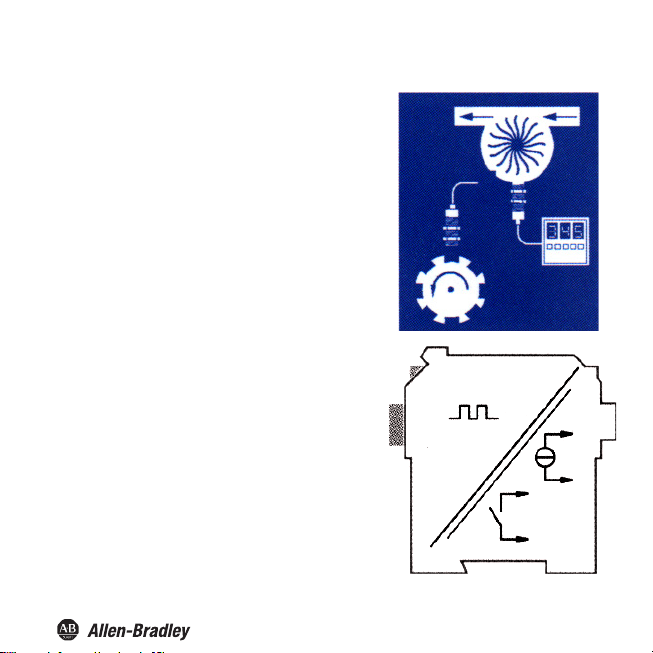
Application Information
Bulletin 937 Intrinsically Safe
between field devices and a process control system/
control
system.
They are suitable for the connection of field devices used in
potentially explosive atmospheres. Safe field circuits for
these devices are intrinsically safe and are galvanically
isolated from non-intrinsically safe circuits. establish an
electroma gnetic separation be tween the potentially
explosive atmospheres and the safe areas in a system.
Typical applications for the Bulletin 937 universal
frequency converter are flow and RPM measurements.
The universal frequency converter accomplishes this by
converting an input frequency into a
frequency-proportional current which can, for example,
then be redirected to a display device or the analog input of
the process control system/control system.
Moreover, the universal frequency converter can be used
universal frequency converter as a signal divider and as a
rotational speed controller (limit-value display for MAX
alarm and for MIN alarm).
Convertes transmit signals
3
Page 6
Bul. 937C Universal Frequency Converter Installation Instructions
Catalog Number Explanation
The following
versions of the universal frequency converter are available:
937CU-DIFRQ-__1
Code Description
DC Supply Voltage: 24 VDC or via Power Rail (24 VDC) Interface
BC Universal Supply voltage:
From 20 VDC up to 90 VDC
From 48 VAC up to 253 VAC
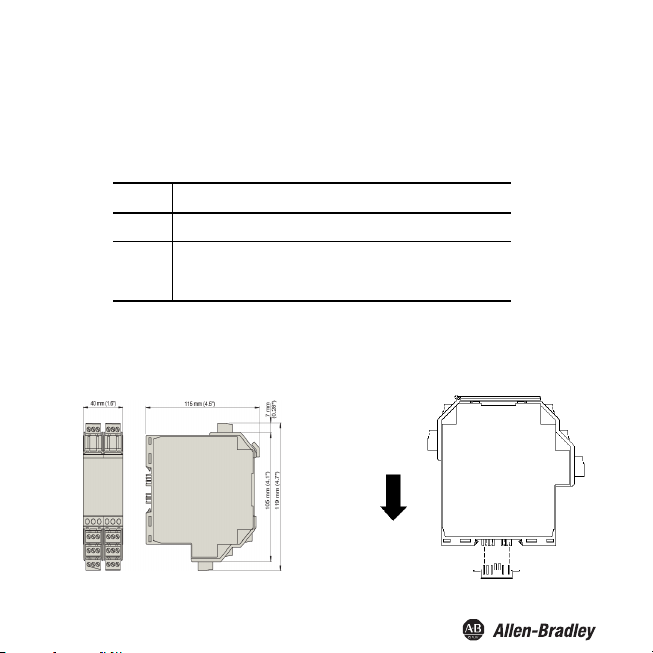
Installation
The Universal Frequency Converter (UFC) can be mounted on a 35 mm standard rail corresponding to
IN EN 60175. The devices must be snapped onto the rail vertically, and never slanted or tipped to the
D
side.
4
Page 7
Bul. 937C Universal Frequency Converter Installation Instructions
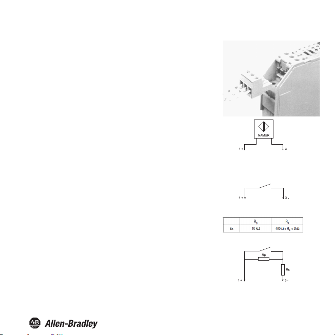
Connection
The removable terminals of the Bulletin 937 Converters simplif y the
connection and the switch cabinet assembly. They make it possible to
replace devices quickly and without error if a customer service becomes
necessary.
Terminals are equipped with screws, are self-opening , have a large
connection area for a wire cross-section up to 2.5 mm/14 AWG and
coded plugs, making it impossible to mix them up.
The intrinsically safe field circuit is connected to the blue
terminals 1 and 3. These may be g uided into the potentially
explosive areas with connector cables in accordance with
DIN EN 60079-14. Terminal 2 is always left unconnected.
The non-intrinsically safe field circuit is connected to
terminals 1 through 3.
Yo u c an co nn e ct :
• A sensor corresponding to DIN EN 60947-5-6
(NAMUR)
chanical contact
A me
•
For sensors that do not have the appropriate internal
resistors, you can add the following externally (as close as
possible to the sensor):
• A series resistor for short circuit monitoring
In reference to these monitoring options, please see also
Units.
5
Page 8
Bul. 937C Universal Frequency Converter Installation Instructions
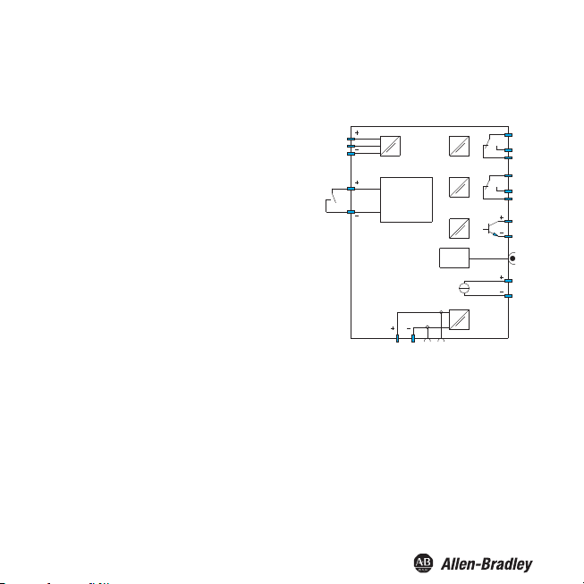
23
24
14
13
RS232
2
3
1
7
8
20
18
19
17
16
12
11
10
Start-up
override/
pulse
suppression
Ter min al s
Terminals 4 ... 6 do not exist for the universal frequency converter.
The functions of the other black terminals are as follows:
• Terminals 7/8: current output (9 unused)
• Terminals 10 ... 12: relay 1
erminals 13/14: start-up override or pulse suppressi
• T
nput (15 unused)
i
• Terminals 16 ... 18: relay 2
• Terminals 19/20: transistor output (21 unused)
• Terminals 23/24: power supply
(22 unused)
• On the exact terminal assignments, please see also the data
sheet.
on
6
Page 9
Bul. 937C Univers
Display Modes and Operation
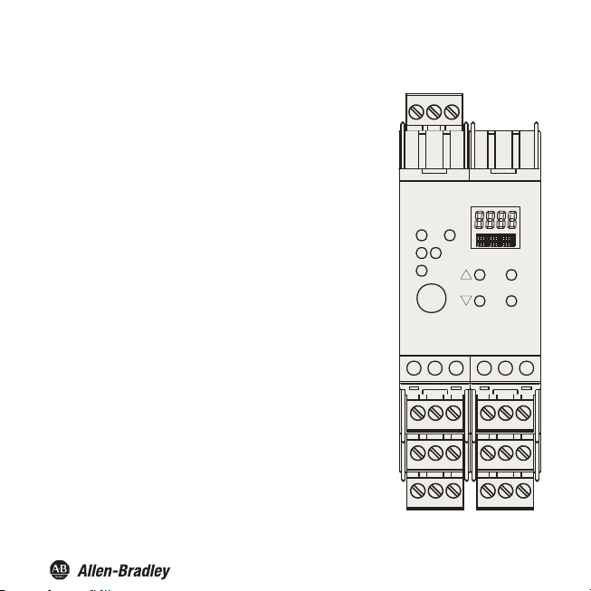
Front side of the Universal Frequency Converter
LED Indicators
IN CHK 1
• Flashing yellow cyclically - indicates input pulses
• Flashes red - indicates input malfunction
• Continuous red - indicates device malfunction
PWR (green)
• For displaying the supply voltage
LED OUT 1 (yellow)
• Indicates relay 1 active
LED OUT 2 (yellow)
• Indicates relay 2 active
LED OUT 3 (yellow)
• Indicates transistor active
RS 232 serial interface
• For connection to a PC for configuration and dia gnosis of the
universal frequency converter using FDT
Display
• Shows measurement values and malfunctions and for
parameterization mode
•
(Up) (Down) ESC (Escape) OK
• Four keys for parameterization on the universal frequency
converter
al Frequency Converter Installation Instructions
654321
1
PWR
IN
CHK
2
1
OUT
3
RS232
19 20 21 242322
esc
ok
10 11 12987
16 17 18151413
7
Page 10

Bul. 937C Universal Frequency Converter Installation Instructions
Display modes and error messages
The current measurement value is shown on the display in normal operating mode. On selecting the
unit, Refer to Units.
If restart inhibit (Refer to Restart inhibit) has been triggered, but the device is still working in normal
mode, a message to that effect appears in the second line of the display.
If a malfunction occurs, one of the following messages is displayed (during appropriate parameterization)
until the malfunction is eliminated:
Err Device error
•
• Err LB for an lead breakage
• Err SC for a short circuit
On selecting error messages Refer to Display modes and error messages. The
switch outputs always revert to a no-current state when there is a malfunction.
Configuring Device Data
WARNING: A change in device data will change the operation of the device!
WARNING: Before ente
installation will result.
FDT Interface
This manual describes Parameterization mode of the universal frequency converter using the control panel. parameterization mode
for the universal frequency converter is more convenient with a PC using Field Device Tool (FDT) software.
Some specialized functions can only be selected using the FDT , for instance, pulse suppression as an alternative to the start-up
override.
The FDT interface is the specification describing the standardized data exchange between devices and control system or engineering
or asset management tools. Examples include: PACTware
FDT frame software can be downloaded from the web: www.pactware.com www.fdtgroup.org.
TM
PACTware
ring new data into the device, you should therefore as certain that no danger to the
TM
, FieldCare, FactoryTalk AssetCentre, and Process Device Configuration.
is trademark of PACTware Consortium
8
Page 11
Parameterization mode control panel
Programming
Bul. 937C Universal Frequency Converter Installation Instructions
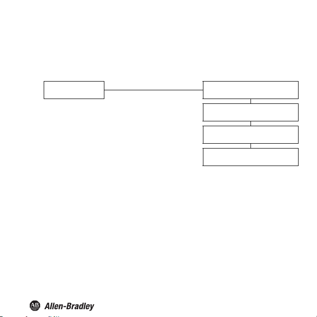
Main menu parameterization mode
Display mode
You can return to display mode from any point in the menu in parameterization mode by pressing the ESC
key (possibly multiple times). If you do not press any key for 10 minutes in parameterization mode, the
device automatically switches back into display mode.
OK + ESC (simultaneously, 1 sec)
ESC
Unit ()
Input ()
Output
Service
9
Page 12

Bul. 937C Universal Frequency Converter Installation Instructions
Password
You can protect the current configuration from unauthorized changes by using a password (See Service;
inactive when universal frequency converter is delivered).
If password protection is active, the various settings in parameterization mode are visible before entry of the
password, but may not be changed. The first time an attempt is made to change a setting, the device
automatically displays a window for entering the password.
• You must enter the password once each time after switching from display mode to parameterization
mode.
• Th
e password cannot be changed and is 1234.
How to enter the password:
automatic switch to password entry
Parameters still protected ESC
Change
attempt
Parameters released OK, value 1234
*If the or keys are pressed, the value changes stepwise ; if the or keys are held down for a longer
period, the value "rolls" to higher or lower values.
Value 0, flashing
, *:
new value, flashing
ESC
OK, wrong value
10
Page 13

Bul. 937C Universal Frequency Converter Installation Instructions
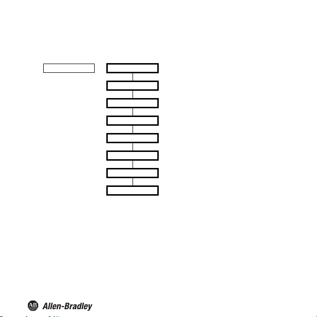
Navigation Method
The following illustration shows the navigation method in parameterization mode using the , , OK, and
ESC keys:
Rel1
OK
ESC
Limit switch
ESC
ESC ESC
ESC
Serial switching
Pulse divider
Error switch
OK
Divider
11
Page 14

Bul. 937C Universal Frequency Converter Installation Instructions
Lowest menu level
Choose Values, Enter Numbers
At the lowest level of the menus, you can either choose betwe en particular possible values for individual
parameters, or enter a numeric value.
Lowest menu level
Parameters
OK
ESC
ESC
current value, flashing
, : ESC
new value, flashing
OK
new value, saved, not flashing
When entering numeric values, please note :
• If you press the or key, the value changes stepwise.
• If you hold the or key for a longer time, the value "rolls" to higher or lower values.
• The sign switches automatically.
• The decimal point is moved automatically.
• The factor of the measurement units will be switched automatically, for example from Hz to kHz.
12
Page 15
Bul. 937C Universal Frequency Converter Installation Instructions
Units
The following illustration shows the units menu. Menu items on the lowest level are outlined in bold.
Unit (see below) —— Hz
rpm
r/sec
l/min
l/h
m³/h
m/s
km/h
The Uni t is used for display of measured values an d for all corresponding settings in parameterization mode.
The universal frequency converter always works internally in Hz (actually in mHz = 0.001 Hz).
13
Page 16

Bul. 937C Universal Frequency Converter Installation Instructions
rpm
Hz 60
Pulses per revolution
--------------------------------------------------------------------=
r/sec
Hz
Pulses per revolution
--------------------------------------------------------------------=
l/min
Hz 60
Pulses pe r liter
---------------------------------------------------=
l/h
Hz 3600
Pulses per liter
---------------------------------------------------=
m³/h
Hz 3600
Pulses per m³
-------------------------------------------------=
m/s
Hz 1000
Pulses per km
--------------------------------------------------=
km/h
Hz 3600
Pulses per km
--------------------------------------------------=
The Uni t is used for display of measured values and for all correspond ing settings in parameterization mode.
The universal frequency converter always works internally in Hz (actually in mHz = 0.001 Hz).
If you want the measurement value to be displayed in rpm or r/sec, the number of input pulses per revolution
must be specified. Units are then converted as follows:
•
•
If you want the measurement value to be displayed in l/min, l/h or m/h, m/s, km/h the number of input
pulses per liter, per m, per m or per km must be specified. The units are then converted as
specifi ed:
•
• (Measurement range restricted: 0.001 Hz ... 550 Hz)
• (Measurement range restricted: 0.001 Hz ... 550 Hz)
• (Measurement range restricted: 0.001 Hz ... 2 kHz)
• (Measurement range restricted: 0.001 Hz ... 550 Hz)
14
Page 17
Bul. 937C Universal Frequency Converter Installation Instructions
Input
The following illustration shows the menus for the input parameters. Menu items on the lowest level are
outlined in bold. Menu items which only appear u
Input —— Lead monitor (se e below) —— LB —— ON LB
Smoothing (see below) —— 0 sec ... 255 sec
Pulses/unit () —— 1 ... 65000
Bounce filter (see below) —— ON Filter
Start-up override () —— 1 sec ... 1000 sec
•For lead fault monitoring, terminal 3 is watched to see whether no current is flowing (lead
break(LB)/open circuit) or the input current is too high (short circuit-SC).
nder certain conditions are marked in grey.
OFF LB
SC —— ON LK
OFF LK
OFF Filter
15
Page 18

Bul. 937C Universal Frequency Converter Installation Instructions
•For lead break monitoring , an appropriate parallel resistor must be present in the sensor or externally. For
short-circuit monitoring, an appropriate series resistor must be present in the sensor or externally
(See Display Modes and operation). No le
pull output stages. If you are using a sensor of this type, you should always select OFF for LB.
•In the case of strongly varying measurement values, you can use smoothing to influence how quickly an
output will reaction to a change in input:
0 sec = no smoothing, 255 sec = maximum smoothing.
•A bounce filter may be necessary when mechanical contacts are used. You can use the bounce filter of the
universal frequency converter if the frequencies to be processed are always lower than 10 Hz.
ad break monitoring is possible for NPN sensors and push-
16
Page 19

Bul. 937C Universal Frequency Converter Installation Instructions
Pulses/unit
The menu option Pulses/unit only appears if you have selected a unit other than Hz for the measurement
value display (See Units).
Depending on the unit chosen, you must enter the number of pulses per revolution, per liter, per m, or per
km. Pulses per km should also be entered for the unit m/s. For conversions, please consult
section .
Examples:
•The speed of a stirring mechanism will be displayed in rpm (or r/sec). The stirring mechanism consists of
8 stirring blades that are detected by the sensor. The number of pulses to enter per unit (revolution) is
therefore 8.
•Flow through a water meter will be displayed in l/min (or l/h). Th e meter returns 20 pulses per liter. This
value should be entered. For a display in m/h, 20,000 pulses per unit (m) should be entered.
•The speed of a conveyor belt will be displayed in m/s (or km/h). The sensor detects 8 pu lses per
revolution on the drive wheel. The drive wheel has a diameter of 0.4 m, thus its circumference is 1.256 m.
Therefore, you should enter 8 1000/1.256 = 6369 pulses per unit (m).
17
Page 20

Bul. 937C Universal Frequency Converter Installation Instructions
Start-up override
Activation of start-up override and its effect:
•You can activate start-up override with a signal to terminals 13/14 (at least 100 ms).
•Start-up override prevents switch outputs from signalling a l imit violation during the configured override
period (start-up phase).
•Start-up override affec ts only those switch outputs with th e MIN switching direction
(Refer to Limit switch). If a switch output has active as its mode of operation, it will remain deenergized during the
energized during the override period (on the mode of operation, Limit switch).
•The start-up override is edge triggered : before it can be triggered again, the signal must be turned off on
terminals 13/14 for at least 200 ms. If a signal interruption occurs and a new signal arrives during the
override period, the timer is restarted.
Pulse suppression:
Usi ng th e FDT
suppression instead of start-up override.
•If pulse suppression is selected, the universal fre quency converter will ignore all incoming pulses, as long
as a signal is pres ent on terminals 13/14. It then behaves f or all evaluations a s though the start va lue of the
measurement range is constantly applied.
•If pulse suppression has been selected , start-up override is deactivated. Restart inhibit is also not possible
(Refer to Restart inhibit).
If problems should occur with the start-up override, use the FDT software to check whether pulse
suppression may have been selected.
override period. If its mode of operation is passive, it will be forced to remain
software (this is not possible with the control panel), you can alternatively select pulse
18
Page 21
Bul. 937C Universal Frequency Converter Installation Instructions
Output
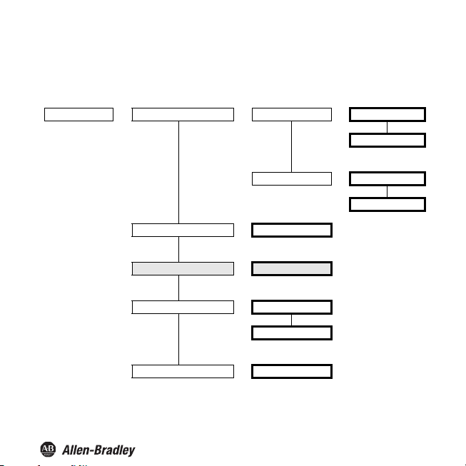
The following illustrations show the menus for the output parameters.
Output —— Rel1 ()
Rel2 () —— same menu as Rel1
OT1 () —— same menu as Rel1
Iout ()
—— Limit switch
Serial switching
Pulse divider
Error switch
Switching outputs
From the Rel1, Rel2 and OT1 menu options, the OK key takes you to a menu in which you can enter
parameters for the selected switch output. The three menus are completely identical and will therefore be
described only once.
When the f unction of a switch outp ut is activated (Limit sw itch, Serial switching, Pulse divider or Error
switch), this is indicated by On. If you want to ac tivate a different function, first sel ect the function with the
and keys. Then press the OK key twice. After the first OK you can still cancel with ESC.
19
Page 22

Bul. 937C Universal Frequency Converter Installation Instructions
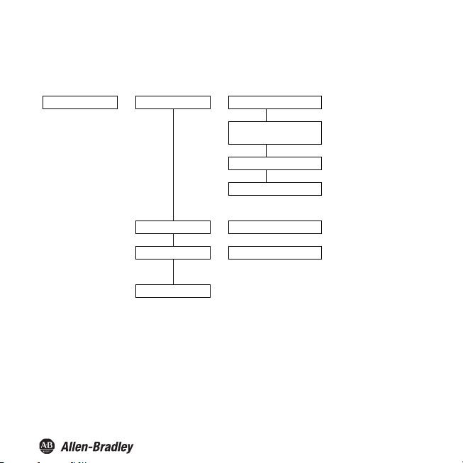
Limit switch
The following illustration shows the menu levels which are accessible through the Limit switch menu option.
Menu items on the lowest level are outlined in bold.
If the Limit switch function is activated (On), the OK key takes you from the Limit switch menu option to the
MIN/MAX menu option. If you activate the Limit switch function (See Switching outputs), then after the
second time you press the OK key, the MIN/MAX menu option will immediately be shown.
Limit switch (On) —— MIN/MAX () —— MAX
MIN
Trip ——
Hysteresis ——
Mode () —— Active
Passive
Alarm freeze () —— On
Off
20
Page 23

Bul. 937C Universal Frequency Converter Installation Instructions
Operating Behavior
Either Max or Min may be selected as operating behavior; either Active or Passive may be selected as
operating mode (See Limit switch). Range of application:
•Switching direction MAX, mode of operation Active : Alarm if trip value exceeded,
for example buzzer on
•Switching direction MAX, mode of operation Pa ss iv e : Overfill protection, monitoring of excessive RPM,
for example pump/drive off; in case of large hysteresis MIN-MAX mode (on/off )
•Switching direction MIN, mode of operation Active: Alarm if trip value exceeded,
for example buzzer on
•Switching direction MIN, mode of operation Passive: Overload protection, monitoring for low spe ed, for
example pump off if there is no more flow
The exact operating behavior of the UFC is shown in the following figure:
21
Page 24

Bul. 937C Universal Frequency Converter Installation Instructions
energized
de-energized
Min
Min + Hysteresis
Max - Hysteresis
Max
energized
de-energized
energized
de-energized
energized
de-energized
Measuring value
Time
Switching direction Max, operating mode Active:
Switching direction Max, operating mode Passive:
Switching direction Min, operating mode Active:
Switching direction Min, operating mode Passive:
22
Page 25

Bul. 937C Universal Frequency Converter Installation Instructions
Switching Point and Hysteresis
When entering values for the switching point and hysteresis, please note:
•
Both values should be entered in the unit that was selected under Unit (Refer to Units). Values
can be entered between 0.001 Hz and 5000 Hz (for non-ex devices: 12 kHz). You can determine the input
limits for a unit other than Hz by using the conversions given in Units.
•Since the Universal Frequency Converter internally converts all values into whole mHz (= 0.001 Hz),
rounding errors may occur in values which you enter in rpm, r/sec, l/min, l /h, m/h, km/h or m/s. If your
application cannot tolerate these small variations in exceptional cases, then select the unit Hz.
•The hysteresis should selected to be > 1 % of the switching point to prevent the relay from fluttering.
•As shown in the illustration of operational behavior in section , in MAX operating mode, the switching
point - hysteresis value must be > 0, while in the MIN operating mode, the value switching point +
hysteresis upper limit switch ing point entry.
All these input limits are automatica lly assigned by the Universa l Frequency Converter.
23
Page 26

Bul. 937C Universal Frequency Converter Installation Instructions
Restart inhibit
Restart inhibit prevents temporary trip value violations or line faults (Err LB, Err SC; Refer to Display
modes and error messages and Input) from not being noticed by operations personnel.
•If Alarm f reeze On has been selected, the ne w state is retained after an output is switch ed until one of the
following actions takes place:
–Device is restarted
–Signal on terminals 13/14
–ESC key pressed.
Each of these actions will cause the switch output to be reset unless the trip value has been violated or the lead
fault is still present.
•If you have selected restart inhibit for an output with the switching direc tion MIN, start-up override must
have been initiated when the device started up (See Start-up override). The Universal Frequency
ter always starts with a 0 measurement value. This will immediately trigger a MIN alarm.
Conver
Without start-up override, the output would then be blocked by restart inhibit.
Using the FDT parameterization software, pulse suppression can be selected as an alternative to start-up
override (See Start-up override).
If problems occur with the restart inhibit, please use the software to check whether pulse suppression has
been selected.
If pulse suppression is selected in this manner, no restart inhibit is possible.
24
Page 27

Bul. 937C Universal Frequency Converter Installation Instructions
Serial Switching
To select th is function, in the se rial switching menu option, press the OK key twice. You can cancel after the
first OK with ESC.
When serial switching is selected, input pulses are switched 1:1 to the switch output. Pulses can then be
evaluate d in the process contro l system/in the control unit. So in this function, the Bu l. 937 device is only an
isolator between intrinsically safe and non-intrinsically safe circuits.
The maximum switching frequenc y at the transistor output is 5 kHz; at the relay < 2 Hz. The relays are thus
only suitable as serial switching outputs in exceptional cases.
25
Page 28

Bul. 937C Universal Frequency Converter Installation Instructions
Pulse length
1
4
---
Pulse divider
max. input frequency
-------------------------------------------------------
<
Pulse Divider
The following illustration shows the menu levels wh ich follow the Pulse divi der menu option. Menu items on
the lowest level are outlined in bold.
If the Pulse divider function is activated (On), the OK key takes you from the Pulse divider menu options to
the Divider ratio menu. When you first activate the Pulse divider function, after the second
Divider ratio
key, the
Pulse divider (On) —— Divider ratio (see below) —— 1,000 ... 99990
The number of input pulses is divided by the divider ratio and switched to the output. The relays can only be
used in certain cases as signal divider outputs due to the maximum switching frequency
< 2 Hz.
Meaning of pulse length: The switch output does not generate a constant frequency. Rather it generates a
potentially irreg ularly occurring num ber of pulses p er unit of time, a ma ximum of 10 pulses per second.
is immediately shown.
Pulse length (see below) —— 750 ms
250 ms
25 ms
where the following must hold:
Example:
•Maximum input frequency 4 kHz, pulse divider 2000
•The following must be true: Pulse length < 0.25 x 0.5 s = 0.125 s.
•Therefore 25 ms should be entered as pulse length.
26
press
on the OK
Page 29
Bul. 937C Universal Frequency Converter Installation Instructions
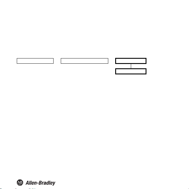
Error switch
The following illustration shows the menu levels wh ich are accessible thro ugh the Error switch menu option.
Menu items at the lowest level are outlined in bold.
If the Error switch function is activated (On), the OK key takes you from the Error switch menu option to the
rm freeze menu option. When you activate the Error
Ala
the OK key is pressed the second time, the menu option
Error switch (On) —— Alarm freeze () —— On
A switch output with the Error switch function is energized in normal operation. If the device encounters
an error condition (See Display modes and error messages), the switch output is switched off.
switch function (See
Alarm freeze is immediately shown.
Switching
Off
outputs), then
after
27
Page 30
Bul. 937C Universal Frequency Converter Installation Instructions
Current output
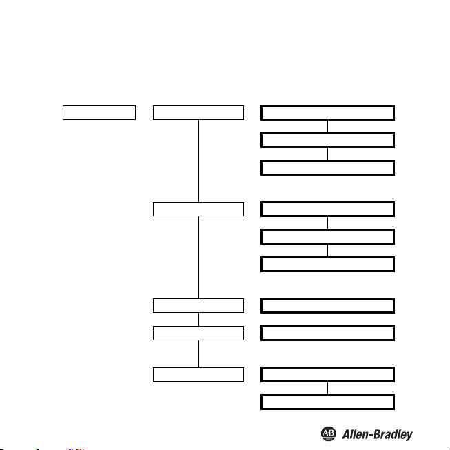
The following illustration shows the menu levels which are accessible from the Iout menu option. Menu
items on the lowest level are outlined in bold.
Iout —— Characteristic () —— 0 mA ... 20 mA
4 mA ... 20 mA, NAMUR NE 43
4 mA ... 20 mA
Fault current () —— Hold
Max
Min
Start value ——
End value ——
inverted () —— inverted
Start value
End value
normal
28
Page 31

Bul. 937C Universal Frequency Converter Installation Instructions
20.5
20.0
0
0
100 102.5mA%
20.5
20.0
0
0100 103
- 1.25
4.0
3.8
mA
%
Current path characteristic
The various settings have the following meaning (for setting the starting value and final value, See Start value
and final value; if you select the inverted characteristic, the conversion of starting value and final value will
be exchanged):
Setting 0 mA ... 20 mA
For this setting, the start value is converted to 0 m A and the final value to 20 mA. Intermediate values are
converted proportional.
Values less than the start value cannot be evaluated (output 0 mA). With values greater than the end value,
the output current increases linearly up to maximum 20.5 mA (102.5 % of the measuring range). Additional
overranges cannot be evaluated (output 20.5 mA).
Setting 4 mA ... 20 mA, acc. NAMUR NE 43
For this setting, the initial value is converted to 4 mA and the final value to 20 mA. Intermediate values are
converted proportional.
If the value fa lls lower than the start val ue, the output current falls linearly to a minimum of 3 .8 mA (-1.25 %
of the measurement range). Additional underranges cannot be e valuated (output 3.8 mA). If the final value is
exceeded, the output current rises linearly to a maximum of 20.5 mA (roughly 103 % of the measurement
range). Additional overranges cannot be evaluated (output 20.5 mA).
29
Page 32

Bul. 937C Universal Frequency Converter Installation Instructions
21.5
20.0
0
0100 110- 25
4.0
mA
%
Setting 4 mA ... 20 mA
For this setting, the initial value is converted to 4 mA and the final value to 20 mA . Intermediate values are
converted proportional.
If the value falls below the start value, the output current falls linearly to 0 mA (- 25 % of the measurement
range). Additional underranges cannot be evaluated (output 0 mA). If the final value is exceeded, the output
current rises linearly to about 21.5 mA (roughly 110 % of the measurement range). Additional overranges
cannot be evaluated (output 21.5 mA).
30
Page 33

Fault current
Bul. 937C Universal Frequency Converter Installation Instructions
Setting Current path characteristic
hold last measured value before fault occurred
Max
(upscale)
Min
(downscal e)
0 mA ... 20 mA
approx. 21.5 mA approx. 21.5 mA approx. 21.5 mA
0 mA (indistinguishable from
underlimit of start ing value)
Current path
characteristic
4 mA ... 20 mA,
acc. NAMUR NE 43
2.0 mA 2.0 mA (indistinguishable from
Characteristic
4 mA ... 20 mA
(indistinguishable from overlimit of
final value)
overlimit of final value)
Start value and final value
During entry of start and final value, please note:
Values should be entered in the selected units.
•
•Values can be entered between 0.001 Hz and 5000 Hz (for non-Ex devices: 12 kHz). You can determine
the input limits
•Since the Universal Frequency Converter converts all values into whole mHz (= 0.001 Hz), rounding
error s may oc cur in va lues wh ich you enter in r pm, r/s ec, l/ min, l/ h, m/h , km/h or m/s. If your app licatio n
cannot tolerate this small variance in exceptional cases, please select the unit Hz.
•
The difference between the final value and the start value should be greater then 1% of the end value.
for a unit other than Hz by using the conversions that are given in Units.
31
Page 34

Bul. 937C Universal Frequency Converter Installation Instructions
Service
The following illustration shows the menus for the service parameters. Menu items on the lowest level are
outlined in bold.
Service ——
Password
Language —— DE (German)
Reset (see below) —— no
—— On
Off
ENG (English)
yes
Reset: If the valu e yes is shown flashing and you press the OK key, all parameters in the Universal Frequency
Converter will be reset to their factory settings. All entries you have ever made in parameterization mode will
be lost.
32
Page 35

Page 36

Publication 937-IN001A-EN-P - April 2014 (DIR 10001098996) 814568
(DIR 10001176478)
Copyright © 2014 Rockwell Automation, Inc. All rights reserved. Printed in the U.S.A .
 Loading...