

Page 1

937CU-AISTR-DC1 Installation Instructions
Strain Gauge Converter
Page 2

Page 3
Symbols Used
Warn ing
Warn ing
Attention
Note
Bul. 937C Strain Gauge Converter Installation Instructions
This symbol warns of possible danger.
Failure to heed this warning may result in personal injury or death, or property
damage, including destruction.
This symbol warns the user of a possible f ault.
Failure to heed this warning can lead to total failure of the device and any other
connected equipment.
This symbol draws attention to important information.
1
Page 4
Safety Notes
Warn ing
Attention
Attention
Attention
Warn in g
Attention
Warn in g
Note
Note
2
Bul. 937C Strain Gauge Converter Installation Instructions
The Frequency Converter with Trip Values must only be operated by trained personnel
in accordance with this handbook.
The protection of operating personnel and of the system is only ensured if the devices
are used in accordance with their intended purpose. Any other type of operation than
that described in this manual places the safety and functionality of the devices and
systems connected to them in question.
The devices may only be installed, connected, and adjusted by electrical professionals
outside the hazardous area.
If faults cannot be elimina ted, the devices must b e taken out of operation and protected
from being placed in service again inadvertently. Tampering with or making changes to
the devices is dangerous and therefore not permitted. They render the warranty void.
The responsibility for the adherence to local safety standards lies with the operator.
Page 5
Overview
Bul. 937C Strain Gauge Converter Installation Instructions
The devices of the Bul. 937C IS Barriers, Isolators and Converters are used to transmit signals
between field
937 products ar
circuits of these devices are intrinsically safe and are galvanically isolated from the not intrinsically
safe circuits. The devices thus represent an electrical isolation between the hazardous area and
the secure area.
Devices can be used
process control system or the control.
Two different, freely parameterisable trip values
Further information (e. g.
instructions for the Bul. 937 family) can be found on our Internet page www.ab.com.
devices and the process control system or control.
e suitable for connection to field devices in the hazardous area. The field current
for signal transmission between field devices in the secure area and the
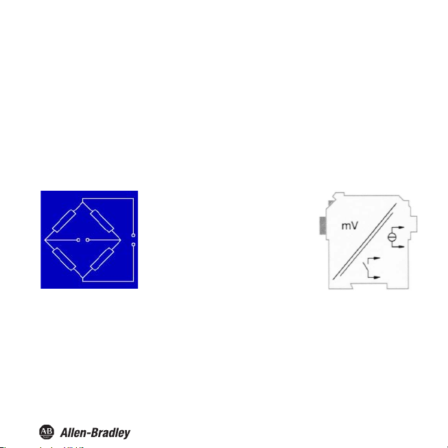
Resistance bridges, i. e. strain gauges,
load cells, force transducers, pressure
transducers, torque shafts or similar
devices, can be connected to the input of
the converters .
The 937CU-AISTR-DC1 converts the
input signal into a proportional output
current, which can be forwarded e. g. to a
display unit or an analog input of the
process control system or control. By
means of the two relay outputs.
of the input signal can be monitored.
certificates and the 937CU-AISTR-DC1 data sheet and the operating
3
Page 6
Bul. 937C Strain Gauge Converter Installation Instructions
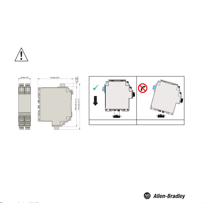
Mounting and Connection
The Strain Gauge Converter can be mounted on a 35 mm standard rail corresponding to DIN EN
60175. The devices must be snapped onto the rail vertically, and never slanted or tipped to the side.
The Strain Gauge Converters are constructed in protection class IP20 and must
therefore be protected from undesirable environmental conditions (water, small
foreign objects).
Attention
CORRECT: Device
snapped on vertically.
INCORRECT: Device snapped
on from the side. Can damage
the contacts and cause the
device to fail.
4
Page 7
Bul. 937C Strain Gauge Converter Installation Instructions
Connection
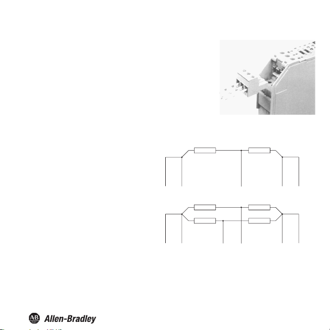
The Bul. 937 series' slip-off terminals significantly simplify
connection and co
quick and error-free exchange of the unit when service is
needed.
The terminals can be screwed on, are self-opening, and have
generous connection room for a wire diameter of up to 2.5 mm²
and coded plugs, so that leads cannot be confused.
The intrinsically safe field circuit is connected
to
the blue terminals 1 to 6 of the Strain
. auge Converters. This may be conducted
into the hazardous area using DIN EN
60079-14-compliant leads.
The non-intrinsically safe field circuit is
connected to the black terminals 1 to 6 of
the Strain Gauge Converters.
In both cases you can connect:
• a half bridge (terminals 1, 3, 4, 5, 6)
• a full bridge (terminals 1 to 6)
nstruction of switching cabinets. They allow
5
Page 8
Terminals
Bul. 937C Strain Gauge Converter Installation Instructions
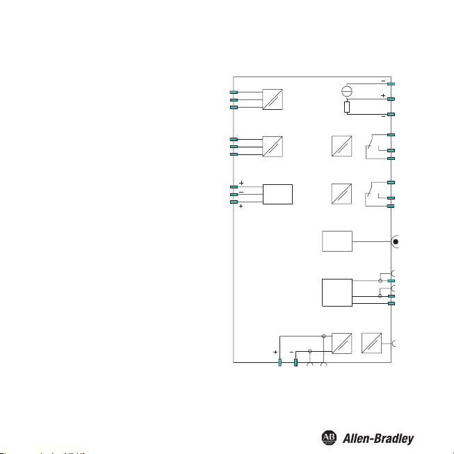
The remaining green terminals have the
following functions:
• Terminals 7/8: current output
• Terminal 9: only for voltage output (see
below.)
• Terminals 10 ... 12: relay 1
• Terminals 13/14: binary input 1
• Terminals 15/14: binary input 2
• Terminals 16 ... 18: relay 2
• Terminals 19 ... 21: RS 485 interface
(deactivated if plug is in RS 232 interface)
• Terminal 22: not used
• Terminals 23/24: power supply 24 V DC
If you connect terminals 7 and 9 by means of a
bridge, a voltage output of - 10 V ... + 10 V
results between this bridge and terminal 8. The
built-in shunt resistance is 500 Ω.
The RS 485 interface is galvanically isolated
from other circuits. It is deacti vated if you plug a
connector into the socket of the RS 232
interface on the front panel of the Strain
Gauge Converters.
Further information on connecting the Strain
Gauge Converters (e. g. on using the Power
Rail) can be found in the data sheet and in the
operating instructions for the Bul. 937 system
on our Internet page www.ab.com.
6
GND
7
8
9
1100
1111
1122
1166
1177
1188
P
21+
N
1920
1
2
3
4
5
6
1133
1144
1155
Binary
inputs
2233
RS 232
RS 485
2244
Page 9
Bul. 937C Strain Gauge Converter Installation Instructions
Front panel
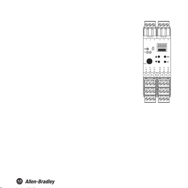
On the front panel of the
• LED ERR (red) to indicate
a sensor fault (flashes red)
−
− the simulation mode (only when using FDT flashes red)− a
device fault (steady red)
• PWR LED (green), to indicate the presence of the supply voltage
• LED OUT 1 (yellow), to indicate that relay 1 is active
• LED OUT 2 (yellow), to indicate that relay 2 is active
• serial RS 232 interface to connect to a PC for parameterisation and
diagnosis of the Strain Gauge Converter using FDT.
• a display for measured value and error message display and for
display during parameterisation mode
•
four buttons for parameterisation of the Strain Gauge Converters
− S (Up)
− T (Down)
− ESC (Escape)
− OK
Strain Gauge Converters you will find:
Display mode and error messages
Meas
ured value display
• In normal operation, the current net value is indicated on the display in the selected unit.
• If you hold down the T key, the current gross value is indicated on the display in the selected unit.
•
If you hold down the S key, the mV value actually measured by the Strain Gauge Converters on
th
e terminals 1 and 2 is indicated on the display.
• As usual, the following applies: net value = gross value - tare
7
Page 10

Bul. 937C Strain Gauge Converter Installation Instructions
Messages during operation
• Alarm freeze
• Hold on error
messages
Error
•
Err INT: error
sensor is connected
•
Err MEM: error in the memory of the Strain Gauge Converters
•
Err SIM: Strain Gauge Converter in simulation mode (only when using FDT.
• Err CELL: cell breakage or no cell connected; for information on selecting the check for sensor
breakage
If you cannot solve the problem by checking the cell and the cell cables and by switching the Strain
Gauge Converters off/on, please contact
In the case of a fault, the relays switch into a state with no current, unless you have selected the
function Hold on error .
in the internal communication of the Strain Gauge Converters; may also occur if no
Rockwell Automation.
Editing device data
WARNING: A change in device data will change the operation of the device!
WARNING: Before entering new
installation will result.
FDT Interface
This manual describes Parameterization mode of the universal frequency converter using the control panel. parameterization mode
for the universal frequency converter is more convenient with a PC using Field Device Tool (FDT) software.
Some specialized functions can only be selected using the FDT , for instance, pulse suppression as an alternative to the start-up
override.
The FDT interface is the specification describing the standardized data exchange between devices and control system or engineering
or asset management tools. Examples include: PACTware
FDT frame software can be downloaded from the web: www.pactware.com www.fdtgroup.org.
TM
PACTware
is trademark of PACTware Consortium
data into the device, you should therefore as certain that no danger to the
TM
, FieldCare, FactoryTalk AssetCentre, and Process Device Configuration.
8
Page 11
Parameterization mode control panel
Programming
Bul. 937C Strain Gauge Converter Installation Instructions
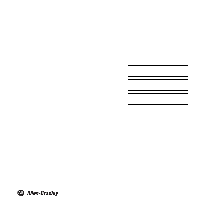
Main menu parameterization mode
Display mode
You can return to display mode from any point in the menu in parameterization mode by pressing the ESC
key (possibly multiple times). If you do not press any key for 10 minutes in parameterization mode, the
device automatically switches back into display mode.
OK + ESC (simultaneously, 1 sec)
ESC
Unit ()
Input ()
Output
Service
9
Page 12
Bul. 937C Strain Gauge Converter Installation Instructions
Password
You can protect the current configuration from unauthorized changes by using a password (See Service;
inactive when Strain Gauge Converter is delivered).
If password protection is active, the various settings in parameterization mode are visible before entry of the
password, but may not be changed. The first time an attempt is made to change a setting, the device
automatically displays a window for entering the password.
• You must enter the password once each time after switching from display mode to parameterization
mode.
• Th
e password cannot be changed and is 1234.
How to enter the password:
automatic switch to password entry
Parameters still protected ESC
Change
attempt
Parameters released OK, value 1234
*If the or keys are pressed, the value changes stepwise ; if the or keys are held down for a longer
period, the value "rolls" to higher or lower values.
Value 0, flashing
, *:
new value, flashing
ESC
OK, wrong value
10
Page 13

Bul. 937C Strain Gauge Converter Installation Instructions
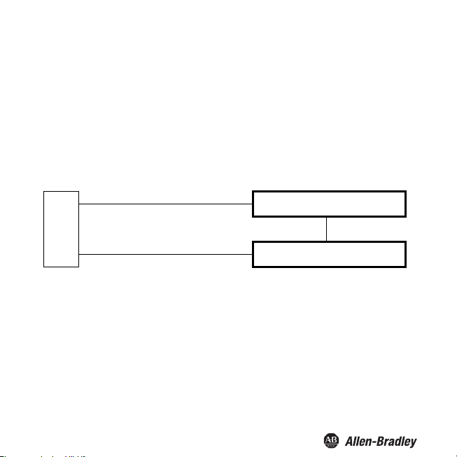
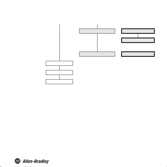
Navigation Method
The following illustration shows the navigation method in parameterization mode using the , , OK, and
ESC keys:
Output
OK →
← ESC
← ESC ← ESC
← ESC
Relay 1
Relay 2
I
out
ST
OK →
ST
Mode of operation
11
Page 14
Lowest menu level
Choose Values, Enter Numbers
At the lowest level of t. e menus, you can
individual parameters, or enter a numeric value.
either choose between particular possible values for
Bul. 937C Strain Gauge Converter Installation Instructions
Lowest menu level
Parameters
When entering numeric values, p
•
o
u press the or key, the value changes stepwise.
If y
•
If you hold the or key
• The sign
switches automatically.
• The d
ecimal point is moved automatically.
Units are automatically converted to higher units, e. g. kg to t, or a factor is displayed, e. g. factor 10
for numbers ≥ 10000.
lease note:
for a longer time, the value "rolls" to higher or lower values.
OK
ESC
ESC
current value, flashing
, : ESC
new value, flashing
OK
new value, saved, not flashing
12
Page 15
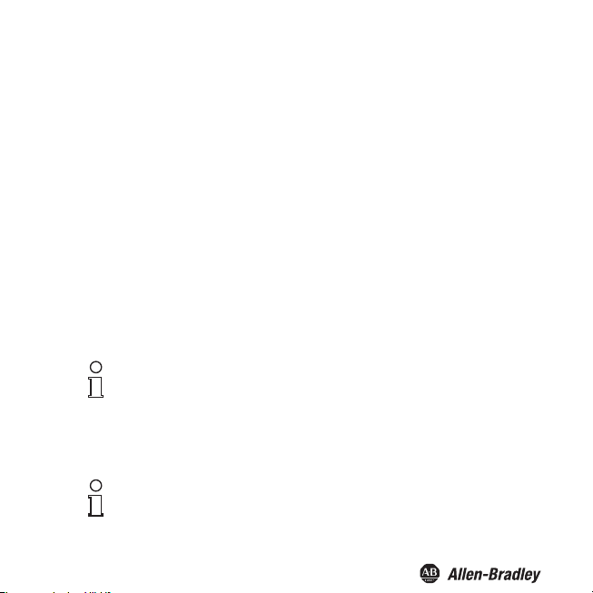
Bul. 937C Strain Gauge Converter Installation Instructions
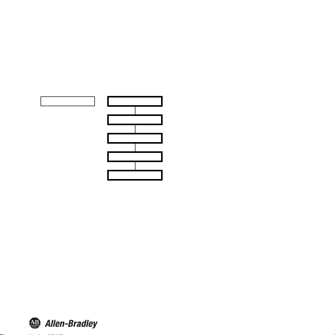
Unit
The following figure shows the menu for the unit. The menu options of the lowest menu level are
surrounded by a bold box. The unit is used for the measured value display (net and gross) and for all
respective settings in the parameterisation mode.
Unit —— kg*
N
%
cbm (m³)
pcs (pieces)
* If more than 9999 kg are entered, the unit changes automatically from kg on t!
The Strain Gauge Converter makes measurements in mV.
13
Page 16
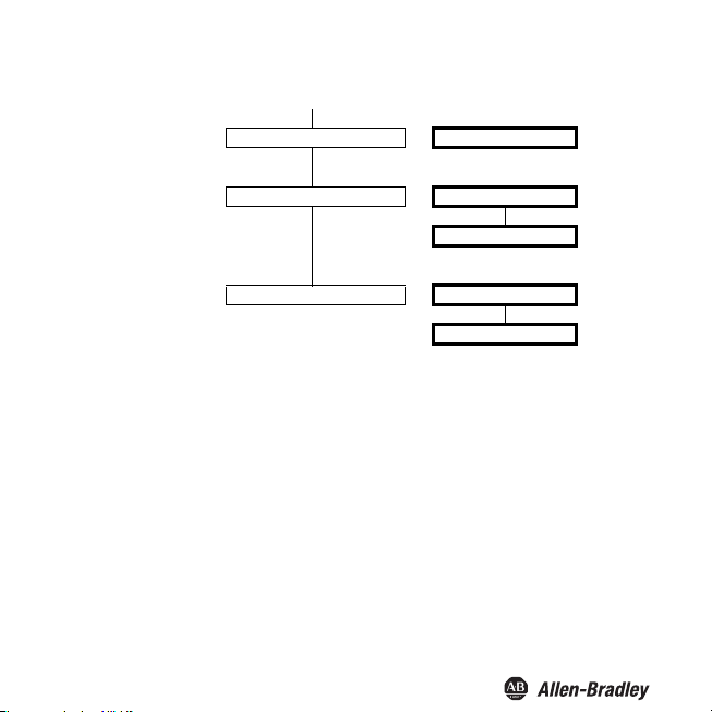
Bul. 937C Strain Gauge Converter Installation Instructions
Sensor
The following figures show the menus for the input parameters. The menu options of the lowest menu
level are surrounded by a bold box. Menu options that are only displayed if you have selected certain
parameter values elsewhere are highlighted in grey.
Input —— Sensor ——
Excitation
—— 1 V
2 V
3 V
4 V
5 V
Sensitivity
Cell rating
Rate
continued on next page continued on next page
—— 0.001 to 60.00 mV/V
—— 0.001 kg to 999.9 t
—— normal
fast
Edition 06/2008 182694
14
Page 17
Bul. 937C Strain Gauge Converter Installation Instructions
Calibrati
Trigger 1
Trigger 2
on
Cell detect
Smoothing
—— On
Off
—— 0 sec to 10 sec
15
Page 18
Bul. 937C Strain Gauge Converter Installation Instructions
Excitation, Sensitivity, Cell rating
• For the values of these parameters, please refer to the technical data of the sensor.
• The supply voltage exists between terminals 3 and 4.
• When connecting several measuring cells in parallel, the supply voltage and sensitivity must be
transferred, the cell data are to be totalled. Only cells of the same design and with identical cell
data may be connected in parallel.
• For a resulting total sensor resistance of R < 100 Ω the supply voltage 5V must not be selected.
The maximum permitted supply voltage is calculated as follows:
Supply voltage = 49 mA x total resistance of the measuring cells
•For th eCell data parameter, the maximum cell load must be set in kg (even if a different unit has
been selected).
The cell data can be set up without a measuring cell being connected. The Strain Gauge
Converter can then be connected
voltage created by the weighing cell due to the load is converted linear into the corresponding
gross weight.
nt to use the Strain Gauge Converter without calibration yet take into account
If you wa
an existing empty weight (e. g. an empty tank or a weighing platform) when
measuring, do not use the function "Zero point" but the function "Tare".
Note
Please note that mechanical influences have not yet been taken into account (e. g. acting of forces on
the weighing cell other than perfectly vertically) so that the weighing device does not achieve its
optimum accuracy.
To take into account mechanical influences a calibration of the fully
device using defined loads is unavoidable.
Note
to the weighing cell and is basically ready for operation. The
installed weighing
16
Page 19

Bul. 937C Strain Gauge Converter Installation Instructions
Without adjustment , the gross value is calculated as follows:
e in
----M---e-----a---s---ur-----ed------ v------a--lu---------
Gross value
This results in the following assignment: 0 mV is converted into 0 unit, the maximum sensor signal (=
sensitivity x excitation voltage) is converted into the maximum cell load of the selected unit, interim
values are converted proportionally.
Maximum cell load
= Cell rating/(kg/unit)
---------- -----------
=
Sensitivity × Excitation voltage
Unit
--------
mV
------
ll ra
-----Ce--------
------ti-----ng-- -
×
kg/unit
0
0
Maximum sensor signal
= Sensitivity x Excitation voltage
Rate, Cell error, Smoothing
• If you have selected the fast setting for Rate, the Sensor failure and Smoothing menu options are
not displayed. In this case, a check for sensor breakage and smoothing is not possible.
Note
• If you have selected the On setting for Sensor failure, a check for sensor breakage is performed
after each measurement (terminals 1 and 2). Possibly, the Strain Gauge Converter returns the
error message Err CELL. Unless this check is enabled the Strain Gauge Converter might
process uncontrolled input values until the sensor failure has been detected.
mV
17
Page 20

Bul. 937C Strain Gauge Converter Installation Instructions
• The settings influence the measuring cycle time:
• By means of Smoothing, you influence the reaction of the Strain Gauge Converter to strongly
fluctuating measured values.
The Strain Gauge Converter processes the smoothed value instead of the current measured
value. With an adjusted smoothing time of 0 sec, the input value is processed directly. The
largest smoothing is reached with the attitude 10 sec. Note please that with increasing smoothing
also the response time of the Strain Gauge Converter is reduced.
Smoothing is designed as a first-order low-pass filter. The smoothing time is the time required by
the output signal to get from 10 % to 90 % after a jump stimulation.
18
Page 21

Bul. 937C Strain Gauge Converter Installation Instructions
Calibration
The following figure shows the menu levels following the Calibration menu option. The menu options
of the lowest menu level are surrounded by a bold box. Menu options that are only displayed if you
have selected certain parameter values elsewhere are highlighted in grey.
Calibration ——
Zero
—— Set
—— -100 to +100 mV
Adjust
Range
kg/unit
Execute
—— Weight
Execute
—— Set
Execute
—— 0.001 kg/unit to 999.9 t/unit
—— yes
—— 0.001 kg to 999.9 t
—— yes
—— see zero point & adjust
—— yes
no
no
no
19
Page 22

Bul. 937C Strain Gauge Converter Installation Instructions
Zero point
For installations where a signal of 0 mV does not correspond to the measured value 0 in the selected
unit, a zero offset can be stored.
• If the zero offset is known from the data of the installation, please enter the value under Set
displays.
• If you select (after appropriate measures in the installation, e. g. removing all weights) Execute and
then Yes, the current mV measured value is stored as zero point. The gross value, the net value
and the tare are set to 0.
For storing the zero point by means of the triggers, i. e. without using the control panel keys.
Adjust without mechanical load
The easiest calibration method. However, not all links in the measuring chain will be considered
resulting in some inaccuracies.
• A trigger input must be parameterized as zare
• After installation and connection of the Strain Gauge Converter the corresponding input must be
short-circuited with the measuring cell free from loads.
Adjust with mechanical load
This is the more accurate calibration method because the whole measuring chain is included. It does,
however, require a high effort.
Adjust
The adjust is an exact defined excitation of the cell, e. g. by an exactly known weight. The Strain
Gauge Converter requires both the value of the adjust in the selected unit and the
generated input signal in mV:
• First enter the adjust value in the selected unit kg, N, cbm or pcs under Weight. If you have selected
the unit %, the adjust value must be entered in the unit that was selected before the unit was set
to %.
• After excitation of the sensor (applying the weight), select Execute and then Yes. This determines
the adjust value in mV. The tare is set to 0, gross value and net value correspond to the adjust
value in the selected unit.
For determining the adjust value in mV by means of the triggers, i. e. without using the control
panel keys, see Triggers section.
20
Page 23

Bul. 937C Strain Gauge Converter Installation Instructions
Notes on Zero point and Adjust
• For the result of the adjust it does not matter whether you determine the zero point or the
adjust value first.
• Zero point and adjust value must be determined in the same unit (do not change the unit before
both operations have been performed).
•
If you perform the adjust in a unit
kg/unit .
• If you change one of the Excitation voltage, Sensitivity or Cell rating parameters, a new adjust is
required.
After an adjust, the gross value is calculated as follows:
Gross value =
This results in the following assignment: The zero point (in mV) is converted into 0 unit, the adjust
value in mV is converted into the adjust value of the selected unit, intermediate values and values
beyond the adjust value are converted proportionally:
Unit
Adjust
other than kg, a new adjust is required after changing the value
easu
ed
val
u
e
i
V
–
Zer
o
--M---------
-----Ad---r------
---
-----
just in
------
--
---
---n---–--- m-----
------
m
V
Ze
ro
t
-----
---
------
----- p---o---i---n--
× Adjust in unit
po
int
0
0
Zero point Adjust
mV
21
Page 24

Bul. 937C Strain Gauge Converter Installation Instructions
Range
This parameter is required for evaluations in the unit %.
Under Set displays, enter the value that is to correspond to the gross value 100 % in the (before
•
selecting %) selected unit kg, N, cbm
cell load are possible.
• Alternatively, you can select Execute and then Yes after excitation of the cell (e. g. after applying
a corresponding weight). This stores the current measured value as Range.
After a change to the unit %, the gross value is calculated as follows:
Gross value in %
or pcs (see section 7.2). Values between 0 and the maximum
oss va
ue
t ch
ang
---Gr-----------
-----------l------
-----wi------th------ou-------Range
-----------
------e --------
to %
------
× 100 %=
kg/unit
• This menu option is only displayed if N, cbm or pcs has been selected as unit (see section 7.2) or
if % has been selected as unit and N, cbm or pcs has been selected previously.
• The entered value determines the conversion of kg into
− N (approx. 1/9.81 = 0.102)
− cbm (known from the application or to be determined by weighing)
− pcs (known from the application or to be determined by weighing).
• If % has been selected as unit, the factor for converting kg into the previously selected unit must
be entered.
• If an adjust into a unit other than kg is performed, the value kg/unit must be entered before the
adjust. After changing the value kg/unit, a new adjust is required.
22
Page 25

Bul. 937C Strain Gauge Converter Installation Instructions
7.5 Triggers
The following figure shows the menus for trigger 1 and trigger 2. The menu options of the lowest menu
surrounded by a bold box. For information on the binary inputs, see Connection section.
level are
Trigger 1 —— Tare Trigger 2 —— Tare
Adjust Adjust
Zero Zero
Binary input for trigger 1: terminals 13/14 Binary input for trigger 2: terminals 15/14
•
In the case of the Tare setting, a signal of at least 100 ms at the binary input results in the
current meas
tare. As usual, the following applies:
net value = gross value - tare
• In the case of the Adjust setting, a signal of at least 100 ms at the binary input results in the current
measured value of the Strain Gauge Converter being adopted as the value for the adjust.
• In the case of the Zero setting, a signal of at least 100 ms at the binary input results in the current
measured va
Storing the adjust and the zero point by means of the triggers only makes sense, for example, if you
want to avoid operational actions on
ured value of the Strain Gauge Converter being stored as the (new) value for the
lue of the Strain Gauge Converter being adopted as the value for the zero point.
the Strain Gauge Converter.
23
Page 26

Bul. 937C Strain Gauge Converter
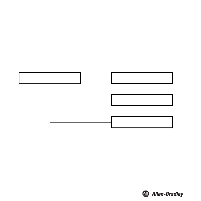
Relays
The following figure shows the menus for the output parameters.
Output —— Relay 1 ——
Installation Instructions
Trip alarm
Fault indication
Relay 2 ——
I
out
From the Relay 1 and Relay 2 menu options, you can use the OK key to get to a menu in which you
can enter individual parameters for the selected relay. Both menus are structured in the same way and
are thus only described once.
The activated function of a relay (Trip alarm or Fault indication) is marked by On. If you want to activate
a different function, first call this function using the S and T keys. Then press the OK key twice. After
the first OK you can cancel with ESC.
Trip alarm
Fault indication
24
Page 27

Bul. 937C Strain Gauge Converter Installation Instructions
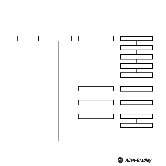
Trip alarm
The following figures show the menu levels following the Trip alarm menu option. The menu options
of the lowest menu level are surrounded by a bold box.
If the Trip alarm function is activated (On), use the OK key to get from the Trip alarm menu option to
the Min/Max menu option. If you reactivate the Trip alarm function, pressing the OK key twice takes
you directly to the Min/Max menu option.
Trip alarm (On) —— Min/Max —— Min
Max
Trip —— Trip point & Hysteresis
Hysteresis ——
Mode —— Passive
Gross/Net —— Gross
continued on next page
Trip point & Hysteresis
Active
Net
25
Page 28
Bul. 937C Strain Gauge Converter Installation Instructions
Delay
Alarm freeze
Hold on error
—— 0 sec. to 250 sec.
—— On
Off
—— On
Off
Operating behavior
As the trip mode Max or Min are possible, as the operating mode Active or Passive are possible.
Areas of application:
• Trip mode Max, operating mode Active: alarm if the signal is above the trip value, e. g. horn on;
protection against overfilling, e. g. open drain in capacity tank
• Trip mode Max, operating mode Passive: protection against overfilling, e. g. conveyor belt/pump
off; for a large hysteresis Min-Max operation, e. g. conveyor belt/pump on/off
• Trip mode Min, operating mode Active: alarm if the signal is below the trip value, e. g. horn on;
protection against shortfalls in security reserves, e. g. conveyor belt/pump on
• Trip mode Min, operating mode Passive: Protection against shortfalls in security reserves, e. g.
pumping out off; for a large hysteresis Min-Max operation
The exact operating behavior of the Strain Gauge Converter is illustrated in the following figure:
26
Page 29

Measured value
Max - hysteresis
Min + hysteresis
Max
Min
Bul. 937C Strain Gauge Converter Installation Instructions
Trip mode Min, operating mode Active:
energized
de-energized
Trip mode Min, operating mode Passive:
energized
de-energized
Trip mode Min, operating mode Active:
energized
de-energized
Trip mode Min, operating mode Passive:
energized
de-energized
Time
Trip point and Hysteresis
When entering the values for the trip point and hysteresis, please observe the following:
• By means of the Gross/Net parameter, you determine whether the value for the trip point is a gross
value or a net value (gross value minus current tare).
• The trip point and hysteresis must be entered in the selected unit.
− The minimum value for the trip point is 0, the minimum value for the hysteresis is 0.1.
− If you have selected Gross, the maximum ce ll load is the maximum value for
the trip point and hysteresis.
− If you have selected Net, the value of the maximum cell load minus the current tare
is the maximum value for the trip point and hysteresis.
27
Page 30

Bul. 937C Strain Gauge Converter Installation Instructions
As the representation of the operating behavior
•
− for the trip mode Max: trip point - hysteresis ≥ 0
− for the trip mode Min: trip point + hysteresis ≤ upper limit of the trip point
in section 7.6.2 shows, the following must apply:
The limits are automatically determined by the Strain Gauge Converter being.
• The hysteresis should be > 1 % of the trip point in order to prevent rapid switching of the relay.
Delay
If you set a time > 0 sec, you prevent short-time violations of the trip value from triggering an alarm.
• The relay only switches if the trip point is exceeded/fallen short of for a period that is longer than
the delay time.
• The relay only switches back if the trip point -/+ hysteresis is fallen short of/exceeded for a period
that is longer than the delay time.
• If the trip point is exceeded/fallen short of for a short time, this does not have any effects.
The following figure shows the operating behavior for the trip mode Max, operating mode Active.
Measured
value
Max
Max - hysteresis
Trip mode Max, operating mode Active, with delay
energised
de-energised
Delay Delay
Time
28
Page 31

Bul. 937C Strain Gauge Converter Installation Instructions
Alarm freeze and Hold on error
• By means of the Alarm freeze you ensure that the operating personnel notices if the trip value is
temporarily violated.
If Alarm freeze On has been selected, the new condition is maintained after switching the relay,
until the ESC key is pressed or the device is restarted. These actions reset the relay, unless the
trip value is still exceeded.
• The Hold on error function prevents the relay from de-energising in the case of a fault.
If Hold on error On has been selected, the condition of the relay is maintained in the case of a
fault , until the error message is cleared. Afterwards, the relay takes up its normal function again.
Fault indication
The following figure shows the menu levels following the Fault indication menu option. The menu
options of the lowest menu level are surrounded by a bold box.
If the Fault indication function is activated (On), use the OK key to get from the Fault indication menu
option to the Alarm freeze menu option. If you reactivate the Fault indication function, pressing the OK
key twice takes you directly to the Alarm freeze menu option.
Fault indication (On) —— Alarm freeze —— On
Off
A relay with the function Fault indication is energised in normal operation. If the device detects a
fault , the relay is de-energised.
29
Page 32

Current output
The following figures show the menu levels following the I
lowest menu level are surrounded by a bold box.
I
—— Characteristic —— 20.20 -/+mA
out
Gross/Net —— Gross
Span —— Gross/Net,Span,Inv
continued on next page
Bul. 937C Strain Gauge Converter Installation Instructions
menu option. The menu options of the
out
4 - 20 NE 43
12.20 -/+mA
0 - 20 mA (b)
Net
30
Page 33

Bul. 937C Strain Gauge Converter Installation Instructions
Fault current
Inverted
—— Min
Max
Hold
Up/down
—— Normal
Inverted
Gross/Net, Span, Inverted
•
By means of the Gross/Net parameter, you determine whether the value for the Span is a gross
value or a net value (gross value minus current tare).
•
By means of the Span parameter, you determine the measured value range which is represented
by the current output.
− The span must be entered in the selected unit.
ave selected Gross, you can enter values between 1 % and 100 % of the maximum cell
− If you h
load.
− If you have selected Net, you can enter values between 1 % of the maximum cell load and the
value of the maximum cell load minus the current tare.
•
If you select Inve
current output and the Span is converted into the end value (for the Strain Gauge Converter
always +20 mA). If you select Inverted → inverted, the Span is converted into the start value of
the current output and the measured value 0 is converted into the end value.
rted → normal, the measured value 0 is converted into the start value of the
31
Page 34

Bul. 937C Strain Gauge Converter Installation Instructions
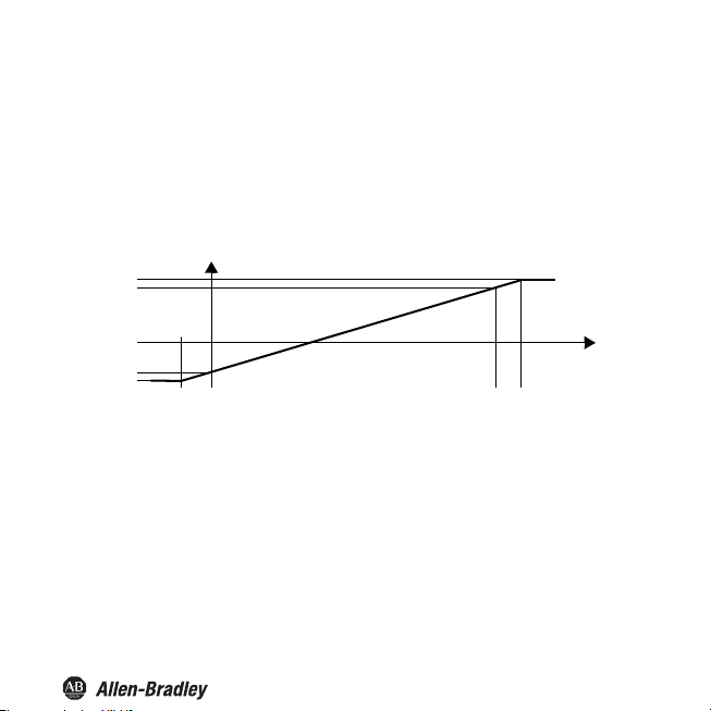
Characteristic
The settings have the following meaning (for Inverted → normal)
Selected setting 20.20 -/+mA
+ 20.5
+ 20.0
mA
0
- 20.0
- 20.5
- 1.25 % 0 100 % = span 101.25 %
This setting converts the measured value 0 into -20 mA (i. e. into 20 mA in the case of changed polarity
at the terminals 7 and 8), the
(terminal 7 -, terminal 8 +), interim values are calculated proportionally.
For values below the measured value 0, the output current decreases linearly to a minimum of
-20.5 mA (-1.25 % of the measurement range). Further underflows cannot be evaluated (output
-20.5 mA). If the span is exceeded, the output current increases linearly to a maximum of +20.5 mA
(101.25 % of the measurement range). Further increases cannot be evaluated (output +20.5 mA).
span is converted into +20 mA
Selected setting 4 - 20 NE 43
20.5
20.0
4.0
3.8
0
- 1.25 %
mA
0 100 % = span ≈ 103 %
32
Measured
value
Measured
value
Page 35
Bul. 937C Strain Gauge Converter Installation Instructions
This setting converts the measured value 0 into 4 mA, the span is co
are calculat
values
For values below the measured value 0, the output current decreases linearly to a minimum of 3.8 mA
(-1.25 % of the measurement range). Further underflows cannot be evaluated (output 3.8 mA). If the
span is exceeded, the output current increases linearly to a maximum of 20.5 mA (approx. 103 % of
the measurement range). Further increases cannot be evaluated (output 20.5 mA).
proportionally.
ed
nverted into 20 mA, interim
Selected setting 12.20 -/+mA
+ 20.5
+ 20.0
0
- 12.0
- 12.5
≈ - 1.6 % 0 100 % = span ≈ 102 %
T
his setting conve
at the terminals 7 and 8), the span is converted into +20 mA
(terminal 7 -, terminal 8 +), interim values are calculated proportionally.
For values below the measured value 0, the output current decreases linearly to a minimum of
-12.5 mA (approx. -1.6 % of the measurement rang e). Further underflows cannot be evaluated (outpu t
12.5 mA). If the span is exceeded, the output current increases linearly to a maximum of 20.5 mA
(approx. 102 % of the measurement range). Further increases cannot be evaluated (output 20.5 mA).
mA
rts the measured value 0 into -12 mA (i. e. into 12 mA in
Measured
value
the case of changed polarity
33
Page 36

Bul. 937C Strain Gauge Converter Installation Instructions
Selected setting 0 - 20 mA (b)
20.5
20.0
0
This setting converts the measured value 0 into 0, the span (see section 7.7.1) is converted into
20 mA, interim values are calculated proportionally.
Values below the measured value 0 cannot be evaluated (output 0 mA). If the span is exceeded, the
output current increases linearly to a maximum of 20.5 mA (102.5 % of the measurement range).
Further increases cannot be evaluated (output 20.5 mA).
Fault curr
ent
The following table shows what the current output is during a fault, depending on the selected setting:
mA
0 100 % = span 102.5 %
Measured
value
Setting
Min
(downscale)
Max
(upscale)
Hold last value before the fault
Up/down in the case of Err Cell: downscale; in all other cases: upscale
Characteristic
20.20 -/+mA
-21.5 mA 2.0 mA -21.5 mA
+21.5 mA 21.5 mA +21.5 mA 21.5 mA
Characteristic
4 - 20 NE 43
Characteristic
12.20 -/+mA
34
Characteristic
0 - 20 mA (b)
0 mA
(cannot be
distinguished from
measurement ≤ 0)
Page 37

Bul. 937C Strain Gauge Converter Installation Instructions
Service
The following figure shows the menus for the service parameters. The menu options of the lowest
menu level are surrounded by a bold box.
Service ——
RS 485: Set the address of the Strain Gauge Converter for communication via the RS 485
interface here.
Reset: If yes is flashing and you press the OK key, all settings of the Strain Gauge Converter will be
reset to factory settings (see exceptions: language and password activation). All entries which you
have ever made in parameterisation mode and the adjust will be lost.
Password
Language —— Eng (English)
RS 485 (see below) —— 0 to 31
Reset (see below.) —— yes
—— On
Off
De (German)
no
35
Page 38

Bul. 937C Strain Gauge Converter Installation Instructions
Factory settings
Menu Parameter Factory setting Local setting
Main menu Unit kg
Input sensor Excitation voltage 5 V
Input adjustment Zero point 0.000 mV
Input Trigger 1 Zero
Output relay 1 Trip alarm On (= selected)
Sensitivity 2,000 mV/V
Cell rating 1000 kg
Rate Normal
Cell error On
Smoothing 0 sec.
Adjust 1000 kg
Range 1000 kg
Tr i g g e r 2 Ze ro
MIN/Max
(= Trip mode)
Trip point 10.00 kg
Hysteresis 10.00 kg
Mode Passive
Net/Gross Net
Delay 0 sec.
Alarm freeze Off
Hold on error Off
Fault indication not selected
Max
36
Page 39

Bul. 937C Strain Gauge Converter Installation Instructions
Parameter Parameter Factory setting Local setting
Output relay 2 Trip alarm On (= selected)
Output I
out
Service Password Off
MIN/Max
(= Trip mode)
Trip point 10.00 kg
Hysteresis 10.00 kg
Mode Passive
Net/Gross Net
Delay 0 sec.
Alarm freeze Off
Hold on error Off
Fault indication not selected
Characteristic 20.20 -/+mA
Net/Gross Net
Span 20.00 kg
Fault current Max
Inverted Normal
Language Eng
RS 485 1
Reset no
Max
37
Page 40

Bul. 937C Strain Gauge Converter Installation Instructions
RS 485 interface
The Strain Gauge Converter can be connected to an RS 485 2-wire bus via the terminals 19 ... 21 or
via the Power Rail. In principle, such a bus is structured as follows:
390 Ω
+ 5 V
B line/+
Strain Gauge
Converter
21
Connection cable 5 m max.
19
220 Ω
390 Ω
Attention
Characteristics of the RS 485 interface of the Strain Gauge Converter:
• Baud rate 9600
• 1 start bit, 8 data bits, no parity bit, 1 stop bit
Bus cable 500 m max.
A line/-
Ensure that the polarity of the connection is correct!
An incorrect polarity causes inverted data signals and thus prevents the bus from
working properly.
38
220 Ω
Connection cable 5 m max.
RS 485 device(up to 31 RS 485 devices)
Page 41

Bul. 937C Strain Gauge Converter Installation Instructions
Requests via the RS 485 interface are not suitable for time-critical or safety-critical
applications.
Warning
The Strain Gauge Converter can request the following information via the RS 485 interface e. g.
from a PC
or a PLC (with 3 decimal places each):
Net measured value (in the set unit)
•
Gross measured value (in the set unit)
•
mV measured value (in the set unit)
•
Output value current output (in mA)
•
The following commands are available for the requests:
• Null: delete the receive buffer of the requesting device
Check_1: checks whether Strain Gauge Converter (with the respective address) is connected
•
• Get_value_ch1: requests the net measured value
• Get_value_ch2: requests the gross measured value
• Get_value_ch3: requests the mV measured value
• Get_current: requests the output value current output
Note
At the beginning of each RS 485 communication, send the re
The RS 485 interface is deactivated if a connector is plugged into the programming
jack (RS 232 interface).
When the connector is removed, the request Check_1 is
communication.
quest Check_1.
required to switch to RS 485
39
Page 42

Bul. 937C Strain Gauge Converter Installation Instructions
The commands must be encoded as follows:
Command 1st byte 2nd byte 3rd byte 4th byte 5th byte 6th byte
Null 00 0 00 0
Check_1 Address 1 Checksum
Get_value_ch1 Address
Get_value_ch2 Address
Get_value_ch3 Address
Get_current Address
The S
train Gauge Converter return
Command 1
st
byte 2
Check_1 Address 9 Checksum
Get_value_ch1 Address Value Checksum
Get_value_ch2 Address Value Checksum
Get_value_ch3 Address Value Checksum
Get_current Address Value Checksum
Explanations:
• Address: The address must be calculated as follows: 128 + setting under Service → RS 485 (see
section 7.8). Values from 128 + 0 to 128 + 31, i. e. from 10000000
• Checksum: The checksum is calculated as follows: 100
code), e. g. for Check_1 for address 17: 100
The figure
•
9 in the response to Check_1 refers to the device type Strain Gauge Converter.
• Value: in the signed long data format (4 bytes or 2 bytes)
B
Checksum
Hex
C
Checksum
Hex
10
Checksum
Hex
D
Checksum
Hex
s the following responses:
nd
byte 3
rd
Hex
byte 4
- (91
Hex
Hex
th
- (1st byte + ... + penultimate byte of the
+ 1) = 6E
byte 5
to 10011111
Bin
= 01101110
Hex
th
byte 6
th
, are possible.
Bin
Bin
byte
40
Page 43

Bul. 937C Strain Gauge Converter Installation Instructions
Example
The weight of a truck load is to be calculated. The empty weight of the truck can be between 7.5 t
and 15 t, the load to be measured can be up to 20 t
alarm is to be triggered at a weight above 20.5 t.
The truck rests on 4 weighing cells which have been connected in parallel at the input of the Strain
Gauge Converter. Each weighing cell ha
• Supply voltage 5 V
• Sensitivity 2 mV/V
• Maximum load: 15 t
• Internal resistance: 350 Ω
The mass of the truck weighing scales is 10 t.
s the following data:
. To prevent an overloading of the truck an
Unit
The weight is to be displayed in the unit tons. In the menu Unit kg must be set. If the weight reaches
1000 kg the device automatically switches to t.
41
Page 44

Bul. 937C Strain Gauge Converter Installation Instructions
Sensor data
Because the truck scale rests on 4 measuring cells the parameters of each individual measuring
cell must be combined: The following entries must
• Supply voltage:
Here the resulting total resistance of the parallel connection of the 4 sensors must be taken into
account. If the resulting resistance of the sensors connected in parallel falls below 100 Ω, a lower
supply voltage must be selected due to the maximum available current. The maximum permitted
supply voltage is calculated as follows:
Total resistance x 49 mA = maximum supply voltage
− 4 measuring cells with each 350 Ω = 87.5 Ω
− 87.5 Ω x 49 mA = 4.2875 V
Set the supply voltage to 4 V.
The maximum permitted total resistance of the sensors is 10 kΩ.
• Sensitivity:
The sensitivity of the individual cells can be accepted 1:1.
Example:
4 cells with 2 mV/V each, entry in Sensitivity = 2 mV/V
• Cell data:
Max. cell load: The cell load of the individual sensor must be multiplied by the number of sensors.
Example:
4 sensors with 15 t each, entry in Cell load = 60 tons).
Explanation:
If e. g. only one cell is loaded at its individual maximum load it will output its maximum voltage. The
other 3 senso
voltage source and results in a voltage drop. Only if all 4 cells are loaded at their respective
maximum loads will they output their respective maximum voltages equally which is then measured
in parallel by the Strain Gauge Converter. All uneven loads between those two extremes behave
linear, therefore the parallel connection can be considered as a single measuring cell.
rs are connected to this voltage and become consumers; this puts a load on the
be made in the menu Sensor:
42
Page 45

Bul. 937C Strain Gauge Converter Installation Instructions
Trigger inputs
One trigger input must be parameterized as "Tare" to enable a subsequent zero point setup.
Calibration
The calibration can be carried out offline or online.
Offline
Calibration without mechanical load is the simplest way of calibrating the Strain Gauge Converter.
However, inaccuracies are to be expected because the whole measuring chain is not included in the
calibration process.
With an empty weighing device setting a zero point for the whole system is possible via the input
parameterized as tare
only the origin is adjusted.
The Strain Gauge Converter is then calibrated. Because the measuring cells are normally calibrated
at factory and are very str
Online
The online calibration is more accurate than the offline calibration because it involves the whole
measuring chain 100%. The measuring cell is put under a defined load and the Strain Gauge
Con
verter calibrated to these points.
The cell returns with an empty weighing platform 1.43 mV. In t
Adjust > Zero point > Execute a zero point calibration is carried out, i. e. the 1.43 mV are allocated
to 0 kg which is now also displayed by the Strain Gauge Converter.
A defined weight must then be placed on the cell, e. g. 5 t.
Under the menu item Input > Calibration > Adjust > Weight the applied weight must now be entered
(5
t) and the calibration be carried out via Execute. The Strain Gauge Converter now displays 5 t.
The processes Zero point calibration and Adjust must always be carried out together, but the
sequence described above does not have to be adhered to (it is possible to calibrate Adjust and then
Zero point.
under "Trigger input". The characteristic of the weighing cell is retained and
ongly linear, the measuring values are calculated with great accuracy.
he menu item Input > Calibration >
43
Page 46

Bul. 937C Strain Gauge Converter Installation Instructions
However, because the total mass to be measured is greater, the range must also be entered|.
Under Input > Calibration > Range > Set the weight to be measured must be entered, in the example
35 t. With this setting the value 100 % will be displayed at 35 t if the unit is changed to %.
The
Strain Gauge Converter has now been calibrated including the whole measur
ing chain.
Outputs
Current output
The current output must only represent the net value (the weight of the load). In the menu Output >
I
> Gross/Net the option
out
The adjustable range relates to the maximum cell load. Because the maximum cell load is not
reached with a full tank (full truck = 20 t, maximum cell load = 60 t) the value 20 t must be
entered here.
Relay outputs
To prevent overloading a relay must be trigge
means that the relay must be parameterized as a limit value switch with the switching direction "Max";
swi
ching point the 20.5 t must be entered. As hysteresis a value of approx. 1 % of the range is
as a
t
recommended, i. e. 250 kg (0.25 t). The relay must energise once the switching point has been
exceeded, the direction of action must therefore be entered as "active".
To prevent the relay from switching during the tru
entered under the menu item Relay > Trip alarm > Delay. Limit overruns of less than 60 s duration
will then be ignored.
Net
must therefore be selected.
red as a limit value relay if 20.5 t is exceeded. This
c
k entering the scales a time of 60 s can be
Operation
An empty truck enters the scales. After short-circuiting the inputs of the trigger input previously
p
arameterized as "Tare" a zero point calibration is carried out. The truck is then loaded and the Strain
auge Converter displays only the weight of the load.
G
At the current output the weight of the
fully loaded truck.
for the
Via the RS 485 interface the weight of the load (net weight) can be queried by a PLS via the
command Get_value_ch_1 and be processed numerically.
load is represented by 4 m
A for the empty truck and 20 m
A
44
Page 47

Page 48

Publication 937-IN004A-EN-P - April 2014 (DIR 10001099008)
(DIR 10001176475)
Copyright © 2014 Rockwell Automation, Inc. All rights reserved. Printed in the U.S.A .
 Loading...