

Page 1

937CU-AIHLP-DC1 Installation Instructions
HART Loop Converter
Page 2

Page 3

Symbols Used
Warn ing
Warn ing
Attention
Caution!
This symbol indicates a possible fault.
Non-observance could interrupt devices and any connected facilities or systems, or result in
their complete failure.
Bul. 937C HART Loop Converter Installation Instructions
Danger!
This symbol indicates an imminent danger.
Non-observance will result in personal injury or death.
This symbol warns of possible danger.
Failure to heed this warning may result in personal injury or death, or property
damage, including destruction.
Warning!
This symbol indicates a possible fault or danger.
Non-observance
This symbol warns the user of a possible f ault.
Failure to heed this warning can lead to total failure of the device and any other
connected equipment.
may cause personal injury or serious property damage.
Note
This symbol draws attention to important information.
1
Page 4
Safety Notes
Warn ing
Attention
Attention
Attention
Warn in g
Attention
Warn in g
Note
Note
Bul. 937C HART Loop Converter Installation Instructions
The HART Loop Converter must only be operated by trained personnel in
accordance with this handbook.
The protection of operating personnel and of the system is only ensured if the devices
are used in accordance with their intended purpose. Any other type of operation than
that described in this manual places the safety and functionality of the devices and
systems connected to them in question.
The devices may only be installed, connected, and adjusted by electrical professionals
outside the hazardous area.
If faults cannot be elimina ted, the devices must b e taken out of operation and protected
from being placed in service again inadvertently. Tampering with or making changes to
the devices is dangerous and therefore not permitted. They render the warranty void.
The responsibility for the adherence to local safety standards lies with the operator.
2
Page 5

Bul. 937C HART Loop Converter Installation Instructions
Reference to further documentation
Laws, standards, or directives applicable to the intended use must be observed. In
relation to hazardous areas, Directive 1999/92/EC must be observed.
The corresponding data sheets, declarations of conformity, EC-type-examination
certificates, certificates and Control Drawings if applicable (see data sheet) are
an integral part of this document. You can find this information under
www.ab.com.
Due to constant revisions, documentation is subject to permanent change. Please refer
only to the most up-to-date version, which can be found under www.ab.com.
Marking
HART Loop Converter
Certification under Pepperl+Fuchs GmbH
Lilienthalstrasse 200, 68307 Mannheim, Germany
KFD2-HLC-Ex1.D.2W (937CU-AIHLP-DC1)
BASEEFA 07 ATEX 0174 , for additional certifications, see www.ab.com
E II (1)GD [Ex ia] IIC, [Ex iaD]
Pepperl+Fuchs Statement of Conformity
E II 3G Ex nA II T4 X
Intended Use
The devices are only approved for appropriate and intended use. Ignoring these
instructions will void any warranty and absolve the manufacturer from any liability.
The device must only be operated in the ambient temperature range and at
the relative humidity (non-condensing) specified.
The de
vices are used in Control &Instrumentation (C&I) technology for the galvanic isolation
of C&I signals such as 20 mA and 10 V standard signals or alternatively for adapting or
standardizing signals. Devices that incorporate intrinsically safe circuit are used for
operating intrinsically safe field devices in hazardous areas.
3
Page 6

Improper Use
Protection of the operati
is not being used according to its intended purpose.
equipment is not suitable for isolating signals in high current
The
is noted
Mounting/Installation
Prior to mounting, installation, and commissioning o
familia
The device must not be installed at locations where corrosive vapors may be present. The
devices fulfill a degree of protection IP 20 according to IEC/EN 60529.
The devices are designed for use in pollution degree 2 and overvoltage category II as per
IEC/EN 60664-1.
If used in areas with higher pollution degree, the devices need to be protected accordingly.
Only use power supplies that provide protection against direct contact (e. g. SELV or
PELV) for the connection to power feed modules.
Observe the tightening torque of the terminal screws.
The installation instructions in accordance with IEC/EN 60079-14 must be observed.
Intrinsically safe circuits of associated apparatus (installed in safe areas) can be led into
hazardous areas, whereby special attention must be paid to maintain separation distances
to all non-intrinsically safe circuits according to the requirements in IEC/EN 60079-14.
All separation distances between two adjacent intrinsically safe circuits need to be
observed in accordance with IEC/EN 60079-14.
If "Ex i" protected circuits (intrinsically safe) were operated with non-intrinsically safe
circuits, they must no longer be used as "Ex i" protected circuits.
4
ng personnel and t
separately
r with the
corresponding dat
in the
device and carefully read the instruction manual.
h
7C HART Loop
Bul. 93
e overall system is not ensured if the product
asheet.
f the device you shou
ter
Conver
applications
Installation Instructions
unless
this
ld make
yourself
Page 7

Bul. 93
7C HART Loop
Converter Installation
Instructions
T
he respective
to e
devices with intrinsically safe circuits of associated apparatus (verification of intrinsic
safety). Make sure to observe IEC/EN 60079-14 and IEC/EN 60079-25.
If more channels of one
connection is made directly at the terminals of the device. When verifying the intrinsic
safety, the maximum values for the parallel connection must be considered.
peak values of the field device and the assoc
x
plosion protection should be considered when connecting intrinsically safe field
nected i
device are con
n parallel, make sure the parallel
iated apparatus with regard
Operation, Maintenance, Repair
he devices must not be repaired, changed or
T
product must always be replaced with an original device.
nipulated. If there
ma
Delivery, Transport, Disposal
C
heck the packaging and contents for damage.
Check if
Keep the original packaging. Always store and transport the
Alway
temperature (see data sheet) must be considered.
Disposing
in compliance with the applicable laws and guidelines of the respective country.
a
ve received every item and if the items received are the ones you ordered.
you h
n
s store the device in a clean a
of devices, packaging material, and possibly contained batteries must be
d dry environment. The permitted storage
device in the original packaging.
a defect, the
is
5
Page 8

Product Specifications
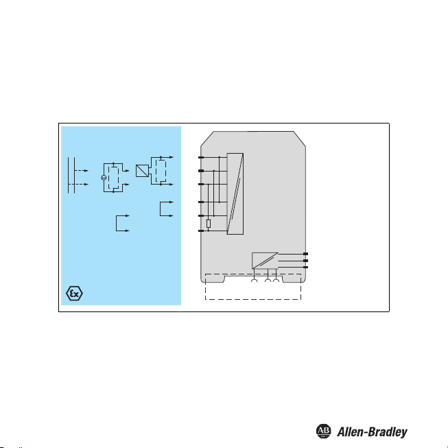
Function
The
HART Loop Converter is an isolated barrier suitable for intrinsically safe applications
The device supplies f
The device analyzes u
variables can be transformed into varying current signals from these four HART
variables. These signals are used to display the values via the analog inputs of the
process control system.
The device is easily configured by the use of key
software.
In addition to the current outputs, the device has two changeover contacts. These
changeover contacts can be programmed so that the changeover contacts function as
trip values for the HART variables
Bul. 937C HART Loop Converter Installation Instructions
ield devices and can be connected in parallel to existing HART circuits.
p to four HART variables (PV, SV, TV, QV). Three HART
pad or with the FDT configuration
6
Page 9
Product Specifications
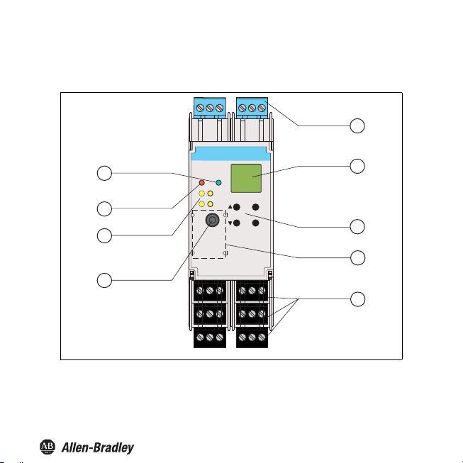
Assembly
Operating and indicating elements
9
8
7
6
OUT
RS232
1 2
ERR PWR
1 2
3 4
7 8 9
13
14 15
192021
Bul. 937C HART Loop Converter Installation Instructions
1
3
6
4 5
2
ESC
10 11 12
16
17 18
222324
OK
3
4
5
7
Page 10
Bul. 937C HART Loop Converter Installation Instructions
1 Removable terminals, blue
2
LC display Display for showing
3
Keypad
ESC
OK
4
Place for labeling
5
Removable terminals, green
6
Programming socket RS 232 serial interface for a connection to a PC for
7
yellow LEDs Outputs Out 1 ... 4, indicating relay status
8
red LEDs Indicating faults
9
green LEDs Indicating power supply
the measured values
the current output values
the fault messages
the parameterization mode
Four keys for selecting the displayed values,
output values and for setting the parameters of the
device Up
Down
Escape
Confirmation
setting parameters and diagnosis of the device using
FDT
the current
8
Page 11
Product Specifications
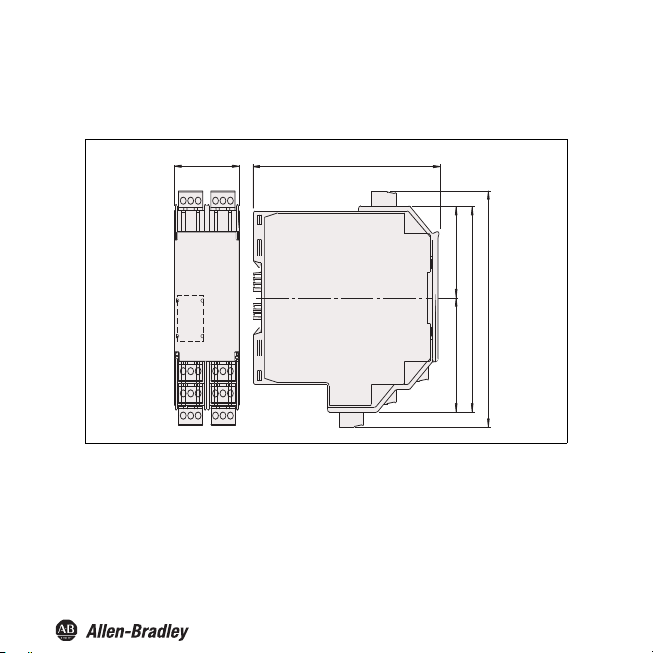
Dimensions
Housi
Bul. 937C HART Loop Converter Installation Instructions
ng
40 mm
(1.6")
115 mm
(4.5'')
46 mm (1.82'')58 mm (2.28'')
104 mm (4.1'')
119 mm (4.7'')
Number of terminal blocks max. 10
Dimension drawing with screw terminals
When using screw terminals with test sockets the device is 124 mm (4.9 in) in height.
When using
spring terminals the device is 131 mm (5.16 in) in height.
9
Page 12
Bul. 937C HART Loop Converter Installation Instructions
Ins
tallation
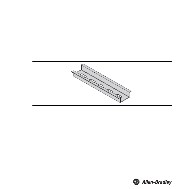
DIN Mounting Rail
The devices are mounted on a 35 mm DIN mounting rail according to EN 60715.
Example: DIN mounting rail(35 mm x 15 mm)
Power Rail
To reduce wiring and installation costs, Power Rail is the optimum solution. The
Rail is a DIN mounting rail with plastic insert, that delivers power to the devices (24 V
DC) and transfers bus signals and a collective error message.
The Power Rail is factory-equipped with cover
and open segments of the Power Rail. Thus, the Power Rail is protected from
contamination. Additionally the cover and end caps prevent that electrically conductive
parts come in contact with the Power Rail.
and end caps. These parts cover empty
Power
10
Page 13
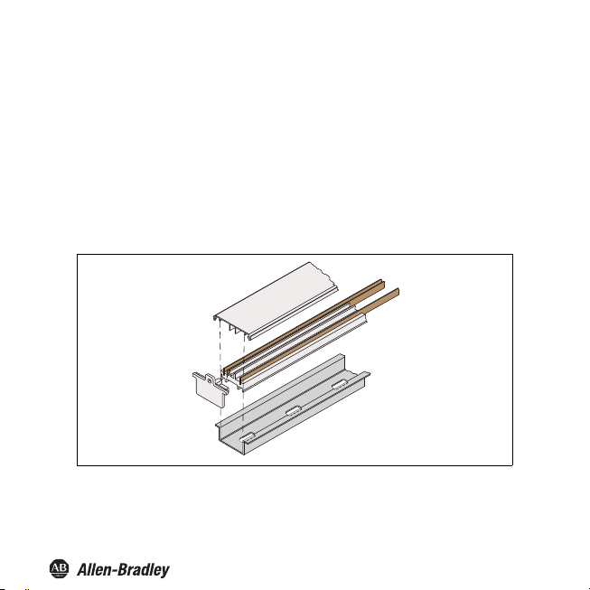
Power Rail is available in two sizes:
Power Rail 937A-PR08 and 937A-PR20
Th
ree leads:
• two conductors for power
•
one conduct
or for collective error messaging
Power Rail
Bul. 937C HART Loop Converter Installation Instructions
11
Page 14
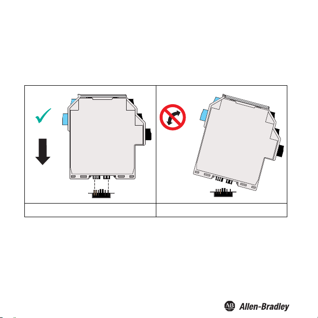
Mounting
Mounting the Isolated Barrier
Snap the device onto the DIN mounting rail in
figure below.
Bul. 937C HART Loop Converter Installation Instructions
a vertical downward movement. See
CORRECT: Device snapped on vertically.
Mounting the Terminal Blocks
The insulation o
replace the terminal blocks, observe the rated insulation voltage. If the rated voltage
greater than 50 V AC, proceed as follows:
1. Switch off
2. Connect the terminal blocks or disconnect the terminal blocks.
12
INCORRECT: Device snapped on from the side.
Can damage the contacts and cause the device to fail.
f the removable terminal blocks protect against direct contact. If you
the voltage.
Page 15

Bul. 937C HART Loop Converter Installation Instructions
Connection
The removable terminal blocks simplify connection and control cabinet construction
significantly. These
with core cross-sections of up to 2.5 mm² (14 AWG). The terminal blocks are coded
with red coding pins so misconnection of terminal blocks are eliminated.
terminal blocks offer adequate space for the connection of leads
Input Connection (field circuit)
Connecting the Field Circuit
1. Connect the field circuit to the blue terminals.
2. Observe the tighteni
0.5Nm ...0.6Nm.
The intrinsically safe fie
lines in accordance with DIN EN 60079-14. You can connect the following field devices:
1.
any separately supplied HART current circuit with transmitter or positioner connected in
parallel
Connection to terminals 2 and 3
a HART-capable active curre
2.
transmitter
Connection to terminals 2 and 3 with bridge between terminals 5 and 6
3.
a 2-wire HART measuring transmitter, e. g
output signal of 4 mA ... 20 mA
The HART measuring transmitter is supplied by the isolated barrier
Connection to terminals 1 and 3
ng torque of the terminal screws. The tightening torque is
ld circuit may be routed in the hazardous area with connection
nt source, e. g., a separately supplied HART measuring
., HART measuring transmitter with an analog
with bridge between terminals 4 and 5
13
Page 16
HART
Bul. 937C HART Loop Converter Installation Instructions
+
+
-
+
mA
-
HART
1+
2+
HART
3-
4
5
250 Ω
6
Zone 0, 1, 2
Div. 1, 2
Power Rail
ERR 24 V DC
14
Page 17
Bul. 937C HART Loop Converter Installation Instructions
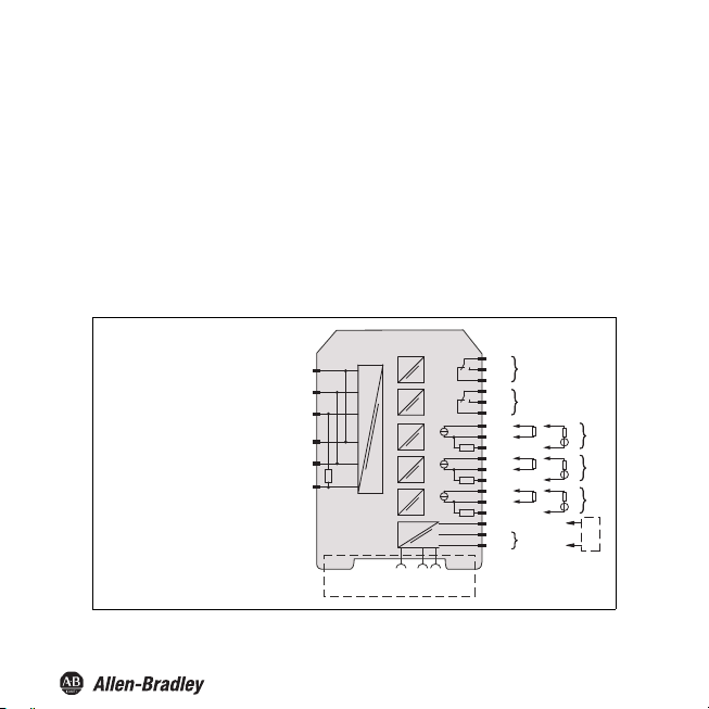
Connection
The following co
Connecting t
1. Connect the drive circuit to the green terminals.
2.
Terminals 10 ... 12: output I (relay 1 (change-over contact))
Terminals 16 ... 18: output II (relay 2 (change-over contact))
Terminals 7
Terminals 13 ... 15: output IV, current output as source (13/14) or
Terminals 19 .
Terminals 22/24: connection of HART handheld
Terminals 23/24: power supply 24 VDC
nnections are available:
he Drive Circuit
he tightening torque of the terminal screws. The tightening torque is 0.5 Nm...0.6 Nm
Note t
... 9: output III, current output as source (7/8) or sink (7/9)
.. 21: output V, current output as source (19/20) or sink (19/21)
250 ˜
ERR 24 V DC
Power Rail
sink (13/15)
10
I
11
12
16
17
II
18
7
13
14+
1519
20+
2122
23+
24-
8+
+
9-
+
+
24 V DC
mA
mA
mA
V
-
V
-
V
-
Zone 2
Div. 2
III
IV
V
HART
15
Page 18

Bul. 937C HART Loop Converter Installation Instructions
Connecting a HART Handheld to the Field Device
You have two options for connecting a HART handheld to
Connection to terminals 22/24 of the isolated barrier.
Connection to the field cables from the isolated barrier to the field
the field device:
device
Transmitting the HART signal using the
Description of HART Operations
Dynamic Query of Variables
Universal HART command 3 is used to query dynamic variables from the field device.
This quer
y is done either directly or by activating burst mode.
Burst Mode
Burst mode is the preferred method because this mode guarantees the fastest signal
transmission. The isolated barrier always tries to set the connected field device to
burst mode
The command for burst mode activation is sent to the field device under
following conditions:
after a restart or
after resetting the isolated barrier after restarting the field d
communication between the field device and isolated
been reestablished again after a time out.
16
current outputs of the isolated barrier is not possible.
the
evice. In the process,
barrier must have
Page 19

Bul. 937C HART Loop Converter Installation Instructions
Polling Mode (command and answer)
The isolated barrier deactivates the burst configuration of the field device. The
isolated barrier performs the field device query using HART command 3.
Procedure to Restore Burst Mode
ated barrier does not receive any more data from the field device in burst mode,
If the isol
the following actions are taken:
The isolated barrier switches to polling mode.
The isolated barrier checks whether another HART master has started in the query
signal circuit. If the
burst mode is interrupted.
If the iso
attempts to activate burst mode.
As soon as the isolated barrier receives a burs
isolated barrier switches from polling mode to burst
This process enables other HART masters to deactivate burst mode momentarily for
service work.
Time Out (communication loss)
When the tim
outputs switch to the defined safe state. Timeout can be adjusted.
isolated barrier has detected a HART master, the restoring of
lated barrier does not detect any other HART masters, the isolated barrier
t message from the field device, the
mode.
eout time has been exceeded in the absence of communication, all
17
Page 20

Bul. 937C HART Loop Converter Installation Instructions
Configuration
Caution!
Fault in the plant
Changing the device data changes the device function.
Before entering new device data, make sure the plant is not endangered by
Attention
changing the device data.
Configuring the Device
Configure the device using the buttons on
buttons for navigation. The following chapters contain more detailed information about
the menus.
The navigation principle is shown using the following example:
Iout1
OK →
← ESC
← ESC
← ESC
← ESC
← ESC
The menu items from the lowest menu level are outlined in bold.
the front side. Use the ,, ESC, and OK
Lowest menu level
Assignment
▼ ▲
Characteristic
▼ ▲
Start Value
▼ ▲
End Value
▼ ▲
OK →
← ESC
4 - 20 NE43
Fault Current
18
Page 21

Bul. 937C HART Loop Converter Installation Instructions
Parameterization Mode
After being switched on, the device is in display m
protection enabled, you must enter the password every time you transition from
display mode to parameterization mode.
Display mode
OK + ESC (simultaneously for 1 s) →
← ESC
Calling up Parameterization Mode
Press the OK and ESC buttons simultaneously for approx. 1
second.
The device changes from display mode to parameterization mode.
Exiting Parameterization Mode
1. Press the ESC once or multiple times.
level you are in.
The device changes from parameterization mode to display mode.
2. If you have not pressed a but
switches back automatically to display mode.
ton for 10 minutes in parameterization mode, the device
ode. If you have password
parameterization mode
▼ ▲
▼ ▲
▼
The number of times depends on which menu
Main menu
Unit
HARTcom
Output
Service
19
Page 22

Bul. 937C HART Loop Converter Installation Instructions
Password Protection
You can activate password protection to protect parameterization from unauthorized
s. Ifpassword protection is enabled, you can viewthe parameter settings but not
change
changethem. Password protection is deactivated during delivery.The passwordis preset
and cannotbechanged by the operator. The password is 1234. Information about enabling
password protection.
Entering the Password
1. As soon as you try to change th e parameterization, the device switches automat ically to
the input window for password access.
The first digit of the password flashes.
2. Set the first digit of the password using the and buttons.
3. Confirm your entry with OK.
The next digit flashes.
4. Repeat steps 2 and 3, until all digits have been entered.
5. Confirm your entry with OK.
If the password was correct, the device changes to parameterization mode. The
device can now be parameterized.
If the password was not correct, cancel password access and begin password entry
again using step 1.
Canceling Password Entry
You can cancel password entry at any time.
Press the ESC button.
The device switches to display mode.
20
Page 23

Entering Numbers
At the lowest menu level of the Parameter menu,
or entering a numerical value.
Parameter Current value, flashing
Selecting a Numerical Va
1. Select the para
the OK button.
2. Press
The current value flas
Select a value from the list of values using the and
3.
buttons.
The new value flashes. The value is not stored.
4. Confirm your sel
The new value does not flash. The
Entering a Numerical Value
1. Select the parameter where you want to ente
2. Press t
he OK button.
The current value flashes.
3.
To change the value in steps, press the or button. or
To change the value
button.
The new value flashes. The value is not stored.
4. Confirm your
The new value is stored.
lue
meter for which you want to change the numerical value.
ection with OK.
selection with OK.
Bul. 937C HART Loop Converter Installation Instructions
you have the option of selecting
OK →
← ESC
← ESC
← ESC
hes.
more quickly, press and hold the or
▼ ▲ ↓
New value, flashing,
not stored
OK ↓
New value, not flashing,
stored
value is stored.
r the numerical value.
21
Page 24

Entering Floating Point Figures
Bul. 937C HART Loop Converter Installation Instructions
At the lowest me
point figures.
The floating point figures can have the following structure:
nu level of the Parameter menu, you have the option of entering floating
Positive number Input Negative number Input
43210000 43.21 E06 -3210000 -3.21 E06
4321000 4321 E03 -321000 -321 E03
432100 432.1 E03 -32100 -32.1 E03
43210 43.21 E03 -3210 -3.21 E03
4321 432 1 E00 -321 -321 E00
432.1 432.1 E00 -32.1 -32.1 E00
43.21 43.21 E00 -3.21 -3.21 E00
1.234 1.234 E00
0.1234 123.4 E-03 -0.123 -123 E-03
0.01234
0.001234 1.234 E-03 -0.00123 -1.23 E-03
0.0001234 123.4 E-06 -0.000123 -123 E-06
loating point figure, you must enter the following parameters:
For a f
four digits of the mantissa (decimals) for
a minus sign and three digits for t
the position of t
the exponents
12.34 E-03 -0.0123 -12.3 E-03
positive numbers
he decimal point in or after the mantissa
he mantissa for negative numbers
22
Page 25

Bul. 937C HART Loop Converter Installation Instructions
Entering a Numerical Value
1. Select the parameter for which you want to enter the numerical value.
2. Press t
3. Press t
4.
5. Confir
6. Repeat steps 4 and 5, until all dig
7. Confirm your entry with OK.
8.
9. Confirm your entry with OK.
10.
11. Confirm your entry with OK.
he OK button.
The cur
rent value from the mantissa and exponent flashes.
he OK button.
With positive numbers, the first digit of the mantissa
flashes. With
To change the value in steps from 0 to 9, press the or button.
To enter a minus sign, press the until the f
Press t
point.
To specify the value of the exponent, press the or
the exponents from E-33 to E33 in increments of three.
negative numbers, the minus sign flashes.
irst digit is less than 0.
m your selection with OK.
The nex
t digit of the mantissa flashes.
its have been entered.
The position of the decimal point flashes.
he or button to specify the position of the decimal
The exponent flashes.
The new value is stored.
button. You can select
23
Page 26

Unit
Bul. 937C HART Loop Converter Installation Instructions
At the lowest men
for the HART variables.
auto
The device displays the unit which is
devices for the HART variables PV, SV, TV, QV.
custom
The device displays the unit which was defined by you for the HART variables PV,
SV, TV, QV in the Cu
u level of the Unit menu, you have the option of selecting the unit type
transferred from connected HART field
stom Tag menu.
Unit
OK →
← ESC
OK →
PV
▼
← ESC
▼ ▼
Ty p e
OK →
← ESC
auto
custom
OK →
← ESC
see below
← ESC
← ESC
← ESC
Custom Tag
OK →
SV
▼
TV
▼
QV
← ESC
OK →
← ESC
OK →
← ESC
same as PV
same as PV
same as PV
24
Page 27

Bul. 937C HART Loop Converter Installation Instructions
Changing the Custom Tag of HART Variables
1. Select the HART variable for which you wou
2. Press the
3. Select the Custom Tag menu.
4.
5. Confirm y
6.
7. Confirm your entry with OK.
8. Repeat steps
9.
10. Confirm your entry with OK.
Canceling the Value Input for HART Variables You
ca
n cancel the value entry at any time.
Press the ESC button.
OK button.
The device displays:
if a value has not be
If a value is defined: the insert mark on the first character, the following character,
and the symbol
To select one of eight possi
, press the or button.
The insert mark flashes.
To select a character, press
spaces.
To select the s
The new value for Custom Tag has been
en defined: the insert mark and the symbol
ble positions for the insert mark before the symbol
our selection with OK.
the or button.
4 and 7, until all characters have been entered. You can also define
ymbol , press the or button.
ld like to change the custom tag.
stored.
25
Page 28

HARTcom
Bul. 937C HART Loop Converter Installation Instructions
The HARTcom menu offers the
between device and field device. If available, the device activates burst mode of the
HART field device for the fastest possible communication. To query variables (PV, SV,
TV, QV, if present) the device uses the universal HART command 3.
HARTcom
option of specifying the method for communication
OK →
← ESC
Mode
▼
OK →
← ESC
secondary
▲▼
primary
TimeOut
← ESC
▼ ▲
ComControl auto detect
← ESC
OK →
5 s ... 60 s
← ESC
OK →
← ESC
▲▼
▼
▲▼
polling
burst
OK →
OK →
▼
0 ... 15
fixed
← ESC
← ESC
ShortAddress
LocateMethod
▲▼
▲▼
← ESC
← ESC
search
OK →
← ESC
Rebuild
← ESC
On Rebuild
▲▼
OFF Rebuild
26
Page 29

Bul. 937C HART Loop Converter Installation Instructions
Selecting a
Mode
The device functions as primary or secondary HART master according to the
HART standard. The device is compatible with each HART handheld and for every
other HART master.
1.
Use the or buttons to select whether the device should operate as a primary or
secondary HART master.
2. Confirm your selection with OK.
Defining TimeOut
If the device does not receive a valid HART message within the specified
time, the communication fault fault message is output.
1.
To change the time in steps, press the or buttons.
Set the time from 5 s ... 60 s in increments of 5 seconds.
2. Confirm your entry with OK.
Defining ComControl
You can specify the communication type between isolated barrier and field device. The
change in communication type is effective immediately. It is not necessary to restart the
isolated barrier.
1.
Select the type of communication using the or buttons.
2. Select auto detect.
If you select this type of communication, the burst configuration of the field
device is not changed.
3. Choose polling.
If you select this type of communication, the isolated barrier deactivates the
burst configuration of the field device. The isolated barrier performs the field device
query using HART command 3.
4. Choose burst.
If you choose this type of communication, the isolated barrier activates the
burst configuration of the field device for HART command 3.
5. Confirm your entry with OK.
27
Page 30

Editing device data: Input
Note!
Note that the field device can be put into burst mode, in accordance to the isolated
barrier configuration. This also applies when a different HART master is in the HART
circuit. If a different HART master changes the burst configuration of the field device, the
isolated barrier waits until the other HART master logs out of the HART circuit. The
isolated barrier assumes that the other HART master is logged off when it does not
send a message for approximately 60 s. After this period of time, the isolated barrier
activates the burst configuration of the field device.
Defining ShortAddress
The defined short address is needed for identification of the field device during
the localization phase.
1.
To enter a short address between 0 ... 15, press the or buttons.
2. Confirm your entry with OK.
Selecting LocateMethod
According to the HART standard, more than one HART field device can be present in a
HART circuit. But the device can communicate only with a single HART field device.
This HART field device is identified during the localization phase.
1.
Select the localization method with the or buttons.
2. Select fixed.
The device communicates with the field device that has a short address
defined under ShortAddress.
3. Choose search.
During booting, the device searches for the field device with the smallest short
address, beginning with the short address defined under ShortAdress. The address
of the field device found is stored by the device under ShortAddress. This
accelerates the device starting when it boots again.
4. Confirm your entry with OK.
28
Bul. 937C HART Loop Converter Installation Instructions
Page 31

Activating Rebuild
Bul. 937C HART Loop Converter Installation Instructions
If the connection to the field device has been lost, the localization phase can be
performed with Rebuild without switching the device off and on again.
1.
Select On
2. Conf
Rebuild with the or buttons.
irm your selection with OK.
The display On Rebuild flashes.
3. Pres
s the OK button.
The device searches for c
4. Pres
s the ESC button once or multiple times to switch to display mode.
onnected field devices when booting.
Current Outputs
In the Output menu, you have the option of defining current outputs 1 to 3 of the device.
The menu structure is identical for the three current outputs. Current output 1 is described
as an example. For information on relay contact outputs.
OK →
Output Assignment
← ESC
▼
Iout1
OK →
← ESC
Characteristic
Start Value see section
OK →
← ESC
▲▼ ▼
OK →
← ESC
▲▼
OK →
← ESC
▲▼
disabled
PV
▼
SV
▼
TV
▼
QV
4 - 20
unlimited
4 - 20 NE43
▲▼
29
Page 32

Editing device data: Input
Bul. 937C HART Loop Converter Installation Instructions
End Value see section
Fault Current
OK →
Iout2
▼
Iout3
▼
Rel1
▼
← ESC
OK →
← ESC
same as Iout1
same as Iout1
OK →
← ESC
▲▼
OK →
down
← ESC
▼
up
▼
hold
Rel2
cting an Assignment
Sele
The values of th
output. The number of available variables depends on the HART field device. When
selecting disabled, the downscale fault current of 0 mA or 2 mA is constantly present at
the current output, depending on the characteristic.
1.
2. Conf
e selected HART variable (PV, SV, TV, QV) are shown on the current
Select the desired HART variable using t
he or buttons.
irm your selection with OK.
30
Page 33

Editing device data: Input
Bul. 937C HART Loop Converter Installation Instructions
Defining a Characteristic
The choice of characteristic defines th
Measuring underranges or overranges outside the specified range cannot be analyzed.
If measuring ranges are undercut or exceeded, the minimum or maximum value is
issued constantly.
1.
Sele
ct the characteristic using the or buttons.
2. Select the characteristic 4 - 20 unlim
For the characteristic 4 - 20 unlimited, measuring underranges are
analyzed linearly up to 0
up to approx. 23 mA by the device.
3. Select the characteristic 4 - 20 NE43.
For the characteristic 4 - 20 NE43
up to 3.8 mA, and measuring overranges are analyzed linearly up to 20.5 mA by the
device.
4. Confirm your entry with OK.
e limits for measuring underrange and overrange.
ited.
mA, and measuring overranges are analyzed linearly
, measuring underranges are analyzed linearly
Defining the Start Value
Make sure during configuration that the start value is at l
If the start value does not meet this requirement, the start value will not be accepted by
the device.
1. Enter the start value as
"Entering Floating Point Figures" . The defined unit from the Unit
menu is used as the unit.
2. Confirm your entry with OK.
a floating point figure. For entering floating point figures, see
east 1% less than the end value.
Defining the End Value
Make sure during configuration that the end value is at least 1 % greater than the start value.
1. Enter the end value
see "Entering Floating Point Figures" . The defined unit from the Unit menu
is used as the unit.
2. Confirm your entry with OK.
as a floating point figure. For entering floating point figures,
31
Page 34

Bul. 937C HART Loop Converter Installation Instructions
Example
Characteristic 4 - 20 NE43, start value 2 bar, end value 10 bar
mA
20.5
20.0
4.0
3.8
0
1.9
2 10 bar
Defining the Fault Current (fault message)
The type of fault current chosen will define how the current output transmits the
fault message to the controller.
1.
Select the type of fault current using the
2. Select the fault current down.
The fault message is indicated by a low current value.
3. Select the fault current up.
The fault message is indicated by a high current value.
4. Select the fault current hold.
The last measured value before the fault occurred is stored.
5. Confirm your entry with OK.
or buttons.
10.25
32
Page 35

Bul. 937C HART Loop Converter Installation Instructions
Relay Contact Outputs
In the Output menu, you have the option of defining relay contact outputs 1 to 2 of the
device. The menu structure of the four relay contact outputs is identical. Relay contact
output 1 is described as an example.
OK →
← ESC
Iout1
▼ ▲
Iout2
▼ ▲
Iout3
▼ ▲
Rel1
▼ ▲
Rel2
OK →
← ESC
OK →
← ESC
Tr i p
▼ ▲
Faul t
same as Rel1
Output
33
Page 36

Bul. 937C HART Loop Converter Installation Instructions
Selecting Relay Contact Output Me
1.
Select the desired relay contact output using the or
Confirm your entry with OK.
2.
The relay contact output me
The active menu is marked as On.
3.
If you would li
4. Press
the OK button twice.
The active menu is marked as O
5. If you wo
34
uld like to cancel activation, press the ESC button after the first OK.
nus
buttons.
nus trip value and fault signal are displayed.
ke to activate the other menu, select this menu with or .
n. The submenu is displayed.
Page 37

Trip Value
Calling up a Trip Value
1.
Select the Tr
2. If th
3. If the trip value menu is not activated,
is marked as On.
ip value menu with the or buttons.
e trip value menu is activated, press the OK button once.
The Assignment submenu is dis
The Assignment submenu is displayed. T
Trip (On) disabled
Bul. 937C HART Loop Converter Installation Instructions
played.
press the OK button twice.
he trip value menu is activated and
OK → OK →
Assignment
← ESC ← ESC
▼ ▲ ▼
Min/Max
Tr i p see section
Hyteresis see section
OK →
← ESC
▲▼
OK →
← ESC
▲▼
OK →
← ESC
▲▼
PV
▼
SV
▼
TV
▼
QV
min
▼
max
35
Page 38

Bul. 937C HART Loop Converter Installation Instructions
OK →
Mode
▼ ▼
Restart Inhibit
▲▼
Delay
cting an Assignment
Sele
The values of the H
relay contact output. The number of available variables depends on the HART field
device. When disabled is selected, the relay remains constant in a de-energized state.
ART variables selected here (PV, SV, TV, QV) are monitored using a
← ESC
OK →
← ESC
OK →
← ESC
passive
active
On
▼
OFF
0 s ... 250 s
1.
Select the desired HART variable using the
irm your selection with OK.
2. Conf
or buttons.
Selecting the switching characteristics defines the switching direction and the direction
of operation. See applications.
1.
Select the switching direction mi
irm your selection with OK.
2. Conf
3.
ct the direction of operation passive or active with the or buttons.
Sele
irm your selection with OK.
4. Conf
n or max with the or buttons.
36
Page 39

Bul. 937C HART Loop Converter Installation Instructions
implement the following applications:
You can
Switching direction m
range, e. g., sounder on
over
Switching direction m
overrange, e
(pump, heater, ... on/off)
Switching direction min
underrange, e. g., sounder is on.
Switching direction min
underrange, e. g., pump, heating,
p, heater, ... off/on)
(pum
The exact switching characteristics of the device are shown in the following illustration:
Max – hysteresis
Min + hysteresis
ax, direction of operation active: alarm if there is a trip value
ax, direction of operation passive: switch off during trip value
. g., pump, heating, ... off, for larger hysteresis Min-Max operation
, direction of operation active: alarm if there is a trip value
, direction of operation passive: switch off during trip value
... off, for larger hysteresis Min-Max operation
Val ue
Max
Min
Switching direction max, mode active:
energized
de-energized
Switching direction max, mode passive:
energized
de-energized
Switching direction min, mode active:
energized
de-energized
Switching direction min, mode passive:
energized
de-energized
Time
37
Page 40

Bul. 937C HART Loop Converter Installation Instructions
Defining the Tr
1. Enter the starting point as a
2. Confirm your entry with OK.
ip Point
chap
ter 3.5.4. The defined unit from the Unit menu is used as the
unit. See chapter 3.5.5.
Defining Hysteresis
Make sure during input that the hysteresis is at least 1 %
This avoids "fluttering" of the relay.
1. Enter the hysteresis as a floating point figure. For en
chap
ter 3.5.4. The defined unit from the Unit menu is used as the
unit. See chapter 3.5.5.
2. Confirm your entry with OK.
Activating the Restart Inhibit
The restart inhibit is used to prevent momentary trip value violations from not being
noticed by operating personnel.
1.
Use the
2. Confi
rm your selection with OK.
The relay status is retained after switching the relay.
3. If you would like to reset the relay status, press the ESC
or button or re
The r
Defining the Response Delay
Inputting a response delay > 0 s prevents momentary trip value violations from triggering
an alarm.
1.
To change the time i
0 s ... 250 s in increments of 5 seconds.
2. Confirm your entry with OK.
38
floating point figure. For entering floating point figures, see
greater than the trip point.
tering floating point figures, see
or buttons to select On.
start the device.
elay is reset. Exception: there is a trip value violation.
n steps, press the or buttons. Set the time from
Page 41

Bul. 937C HART Loop Converter Installation Instructions
onse delay has the following effects:
Resp
When the value of the trip point is out
of time longer th
When the value of the trip point ± hysteresis is in range (not reached or exceeded) for a
period of time longer
Shorter overranges/underranges do not
The following illustration shows an example of switching
Max – hysteresis
an the delay time, the relay switches.
than the delay time, the relay switches back.
Val ue
Max
of range (exceeded or not reached) for a period
have an effect.
characteristics with response delay
Switching direction max, mode active, with delay:
energized
de-energized
Delay Delay
Time
39
Page 42

Bul. 937C HART Loop Converter Installation Instructions
Fault Message
Calling up a Fault Message
1.
2. If the fault message menu i
3. If the fault message menu i
or buttons to select the Fault message menu.
Use the
The Restart inhibit submenu is disp
s activated, press the OK button once.
layed.
s not activated, press the OK button twice.
The Restart inhibit submenu is displayed. The Fault
activated and is marked as On.
OK →
Restart InhibitFault (On)
← ESC
message menu is
OK →
← ESC
▼
Activating the Restart Inhibit
The restart inhibit is used to prevent momentary trip value violations from not being
noticed by operating personnel.
1.
2. Conf
3. If you would like to reset the relay status, press the ESC or
or buttons to select On.
Use the
irm your selection with OK.
The relay status is retained after switching the relay.
on or restart the device.
butt
y is reset. Exception: there is a fault message.
The rela
On
OFF
40
Page 43

Bul. 937C HART Loop Converter Installation Instructions
Service
Sele
In t
he Service menu, you have the option of specifying basic device parameters.
OK → OK →
Service ENG
Language
← ESC ← ESC
▼ ▲
▼
DE
← ESC
Passw ord
OK →
On Password
← ESC
▲▼
▲▼
OFF Password
← ESC
Reset
▼
OK →
← ESC
On Reset
▲▼
OFF Reset
OK →
← ESC
Ver si on
← ESC
Version No.
ct language
1.
2. Select EN
3. Conf
4. Select DE
5. Conf
or buttons to select which language is used by the device display.
Use the
G for English.
irm your selection with OK.
for German.
irm your selection with OK.
41
Page 44

Bul. 937C HART Loop Converter Installation Instructions
Activating Password Protection
To protect parameterization from unauthorized changes, you can enable
password protection. Information about password protection see chapter 3.5.2.
1.
Use the
2. To enable password protection,
3. Conf
4. To disable password protection, select Off Password.
5. Conf
Resetting the Device to
1.
2. Conf
or buttons to select the desired setting.
irm your selection with OK.
irm your selection with OK.
select On Password.
Factory Settings
the
or buttons to select On Reset.
Use
On Res
et flashes.
irm your selection with OK.
The device is reset to factory settings. All entries yo
in parameterization mode will be lost.
Displaying the Software Version
Use the or buttons to display the
version.
The software version of the de
vice software is displayed.
u have defined
42
Page 45

Editing device data: Default settings
Bul. 937C HART Loop Converter Installation Instructions
Operation
ators during Operation
Indic
The isolated barrier displays the following operating modes and fault messages
during operation.
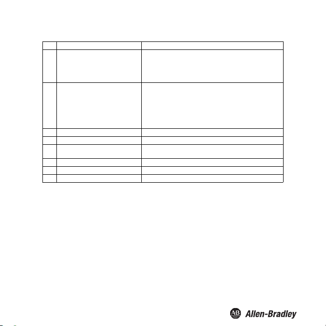
LED Indicators
LED Status Description
Green LED O No power supply
Red LED Flashes briey Displays a single HART fault message received by the eld device
Yellow
LEDs
Flashes regularly Start-up phase, self-test
On Normal function
Flashes regularly Invalid HART data (missing commun ication or fault in the eld
On Device self-test of isolated barrier detected a fault
On Isolated barrier is in reset state, all other LEDs are o
On
device)
Output Out 1, relay energized
Output Out 2, relay energized
43
Page 46

Display Indicators
In normal operation, the display shows:
the current values of the HART
resent current output values for the three current outputs in mA
the p
urrent device status
the c
This display shows information about the device status of the field device (1 byte) and
t the response code (1 byte) of the field device. These two bytes are displayed in
abou
the first line of the display in hexadecimal form with the code RC on the left side.
In the ev
44
rrent setting of the type of communication
the cu
LOOP
•
he isolated ba
T
performs the field device query using the HART command 3.
• LOOP
The isolated barrier performs the field
•
LOOP
The iso
• LOOP Mixed
The isolated barrier performs the field
3 (polling). The field device is in burst mode, however it references a different
HART command than 3.
ent of a fault, the display shows:
Err Device Fault
Displays a device fault in
Err Communication
Displays a communication fault – r
Err Field Device Malfunction
Displays a field device failure – red LED
lashes.
f
Bul. 937C HART Loop Converter Installation Instructions
variables PV, SV, TV, QV in the selected unit
Locate
rrier reestablishes the HART circuit. The isolated barrier
Poll
device query using the HART command 3.
Burst
lated barrier receives the HART command 3 of the field device.
device query using the HART command
the isolated barrier – red LED lights up.
ed LED flashes.
Page 47

Bul. 937C HART Loop Converter Installation Instructions
Display Options for Current Output Values and HART Variables
To select the displayed measured
buttons.
To select units for measured values, use the Unit menu.
Every time the isolated barrier receives a HART command 3 message from the field
he display is updated.
device, t
The isolated barrier displays the current output values as a four-digit number. The
decimal point is set to provide the best possible resolution.
The isolated barrier shows the floating point value for HART variables as follows:
• If possible, as a fo
Negative values are shown on the device with three digits because of the
minus sign.
t is rounded as necessary. For example, the number 0.3456 is shown as
• A digi
0.346.
isolated barrier cannot show the floating point value, the mantissa and
• If the
exponent are shown in alternation.
values or current output values, use the and
ur-digit number with decimal point and without exponent.
Fault Message
The following table shows which fault message the current outputs send
based on the characteristic
Setting 4 - 20 unlimited 4 - 20 NE43
down 0 mA
up approx. 23 mA
hold Last measured value before the fault
Cannot be distinguished from falling
below the start value
Cannot be distinguished from the e nd
value being exceeded
2.0 mA
21.5 mA
to the controller,
45
Page 48

Bul. 937C HART Loop Converter Installation Instructions
Technical Specifications
Default Settings
The following table provides an overview of the default settings. Information about
resetting the device to the default setting see Service.
Tip
If the device parameters have changed, enter these changes in the "Custom Value"
column. This provides an overview of your individual device settings.
Menu Parameters Default setting Custom value
Unit
HARTcom Mode secondary
Output --- Iout1
Output --- Iout2
PV --- Type
SV --- Type auto
TV --- Type auto
QV ---Type
TimeOut 10 s
ComControl auto detect
ShortAddress 0
LocateMethod search
Assignment disabled
Characteristic 4 - 20 NE43
Start value 0.000
End value 100.0
Fault current down
Assignment disabled
Characteristic 4 - 20 NE43
Start value 0.000
End value 100.0
Fault current down
auto
auto
46
Page 49

Editing device data: Default settings
Menu Parameters Default setting Custom value
Output --- Iout3
Output --- Rel1 *
Output --- Rel2 *
Service Language ENG
Assignment disabled
Characteristic 4 - 20 NE43
Start value 0.000
End value 100.0
Fault current down
Trip value On (selected)
Trip value --- Assignment
Trip value --- Min/Max
Trip value --- Trip point
Trip value --- Hysteresis
Trip value --- Operating mode
Trip value --- Restart inhibit
Trip value --- Response delay
Fault message not selected
Trip value On (selected)
Trip value --- Assignment
Trip value --- Min/Max
Trip value --- Trip point
Trip value --- Hysteresis
Trip value --- Operating mode
Trip value --- Restart inhibit
Trip value --- Response delay
Fault message
Password OFF
Bul. 937C HART Loop Converter Installation Instructions
disabled
min
80.00
10.00
passive
OFF
0 s
disabled
min
80.00
10.00
passive
OFF
0 s
not selected
47
Page 50

Page 51

Page 52

Publication 937-IN003A-EN-P - April 2014 (DIR 10001099005) 814570
(DIR 10001176476)
Copyright © 2014 Rockwell Automation, Inc. All rights reserved. Printed in the U.S.A .
 Loading...