

Page 1

937CS-AITMP-DC1 Installation Instructions
Universal Temperature Converter
Page 2
Symbols Used
Warn ing
Warn ing
Attention
Note
Bul. 937C Universal Temperature Converter Installation Instructions
This symbol warns of possible danger.
Failure to heed this warning may result in personal injury or death, or property
damage, including destruction.
This symbol warns the user of a possible f ault.
Failure to heed this warning can lead to total failure of the device and any other
connected equipment.
This symbol draws attention to important information.
1
Page 3
Safety Notes
Warn ing
Attention
Attention
Attention
Warn in g
Attention
Warn in g
Note
Note
2
Bul. 937C Universal Temperature Converter Installation Instructions
The Universal Temperature Converter must only be operated by trained personnel in
accordance with this handbook.
The protection of operating personnel and of the system is only ensured if the devices
are used in accordance with their intended purpose. Any other type of operation than
that described in this manual places the safety and functionality of the devices and
systems connected to them in question.
The devices may only be installed, connected, and adjusted by electrical professionals
outside the hazardous area.
If faults cannot be elimina ted, the devices must b e taken out of operation and protected
from being placed in service again inadvertently. Tampering with or making changes to
the devices is dangerous and therefore not permitted. They render the warranty void.
The responsibility for the adherence to local safety standards lies with the operator.
Page 4
Bul. 937C Universal Temperature Converter Installation Instructions
Overview
The devices of the Bul. 937C IS Barriers, Isolators and Converters are used to transmit signals
between field devices and the process control system or control.
The Bulletin 937 devices are suitable for connection to field devices in the hazardous area. The
field current circui
not intrinsically safe circuits. The devices thus represent an electrical isolation between the
hazardous area and the secure area.
Further information (e. g. certificates, the data sheets for the Universal Temperature Converter and
the operating instructions can be found on www.ab.com.
ts of these devices are intrinsically safe and are galvanically isolated from the
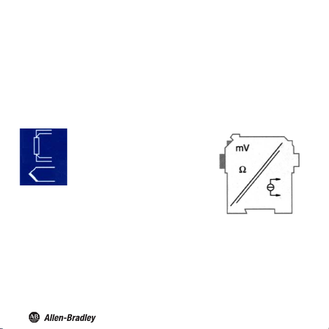
The temperature converter is used
for temperature measurement.
Resistance temperature detectors,
thermocouples, potentiometers or voltage
sources can be connected to the inputs of
the converter.
The Universal Temperature Converter
converts the input signals into proportional
current signals. The output signals can, for
example, be for-warded to displays or
analog inputs of the process control system.
3
Page 5
Mounting
Attention
Bul. 937C Universal Temperature Converter Installation Instructions
The Universal Temperature Converter is constructed in protection class IP20 and
must therefore be protected fr
small foreign objects).
om undesirable environmental conditions (water, dust,
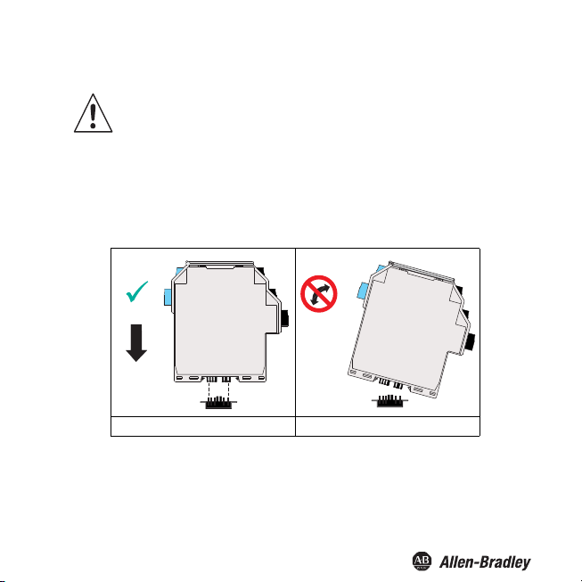
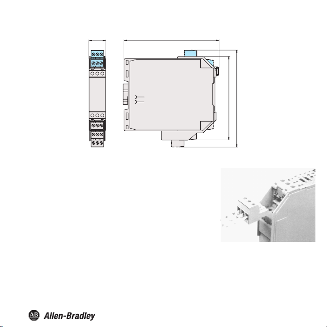
The Universal Temperature Converter can be mounted on a 35 mm top-hat rail corresponding to DIN EN
50022. The devices must be snapped onto the rail
Further mounting alternatives, e. g. using the Power Rail, can be found in the operating instructions for the
Bul 937 at www.ab.com.
CORRECT: Device
snapped on vertically.
vertically, and never slanted or tipped to the side.
INCORRECT: Device snapped on from
the side. Can damage the contacts and
cause the device to fail.
4
Page 6
Bul. 937C Universal Temperature Converter Installation Instructions
20
115
Connection
The slip-off terminals significantly simplify connection and
construction of switching cabinets. They allow
free exchange of the unit when service is needed.
The terminals can be screwed on, are self-opening, and have
generous connection room for a wire diameter of up to 2.5 mm²
and coded plugs, so that leads cannot be confused.
Intrinsically safe field circuits are connected to the blue terminals
1 to 6 of the Universal Temperature Converter. These may be
conducted using DIN
hazardous area.
Non-intrinsically safe field circuits are connected to the black
terminals 7 to 15
Only one sensor can be connected to the Universal
Temperature Converter.
EN 60079-14-compliant leads into the
of the Universal Temperature Converter.
quick and error-
111
118
5
Page 7

Mounting and Connection
Bul. 937C Universal Temperature Converter Installation Instructions
following
The
• Resistance temperature sensors
− Pt10, Pt50, Pt100, Pt500, Pt1000
according to EN 60751: 1995 or
GOST 6651-94
− Ni 100 according to DIN 43760
− Cu10, Cu50, Cu100 according to
GOST P50353-92
in 2-wire, 3-wire or 4-wire technique
• Thermocouples
− Type B, E, J, K, N, R, S, T according to
IEC 584-1: 1995
− Type L according to DIN 43710
− Type TXA, TXK, TXKH according to
GOST P8.585-2001
or a cold junction compen
F
r
equire
accessory instead of
terminal block 1 to 3 or 4 to 6.
• Potentiometers (800 Ω - 20 kΩ) in 3-wire
technique
• Sources for voltage signals between
-100 mV and +100 mV
sensors
the
937A-TCJC ter
can be connected
n (CJC), you
satio
minal blo
th
e normal
:
ck as an
2- 3+
2-1- 3+
equal lead resistances
2-1- 3+ 4+
2-1+
937A-TCJC
2-13+
equal lead resistances
2-1+
6
Page 8
Bul. 937C Universal Temperature Converter Installation Instructions
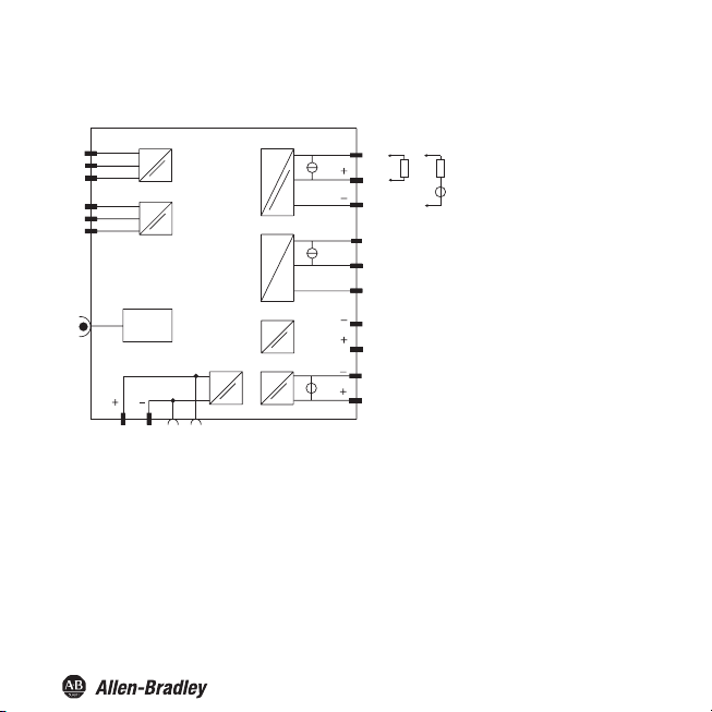
The remaining black terminals have the following functions (10,11,12 NA):
1
2
3
4
5
6
RS 232
14 15
14,15 Power supply 24 VDC
7
8
9
10
11
12
7
8
10
11
7,8 Current output, source
7,9 Current output, sink
7
Page 9

Bul. 937C Universal Temperature Converter Installation Instructions
If a current output is operated as a sink, the voltage across the terminals must be between 5 V and
30 V. An additional resistance is only required if the voltage is above 16.5 V. The resistance must be
between (U - 16.5 V)/0.0215 A and (U - 5 V)/0.0215 A (see diagram).
Example: U = 24 V
(24 V - 16.5 V)/0.0215 A = 350 Ω
(24V - 5V)/0.0215A = 880Ω
R [Ω]
1200
1000
800
600
400
200
0
16 20 25 30
U [V]
Resistance area
8
Page 10

7C
Bul. 93
Universal Temperature Converter Installation Instructions
If a current output is operated as a source, the load resistance must be between 0 Ω and 550 Ω
(535 Ω if the output format is 4 mA to 20 mA unlimited).
Controls and indicators of the Universal Temperature Converter
Front panel of the universal temperature converter:
• LED ERR 1 (red) to indicate
− a lead fault at input 1 (terminals 1 to 3; flashes red)
− the simulation mode (flashes red)
− a device fault (steady red)
• LED PWR (green) to indicate the supply voltage
USB interface to connect to a PC for parameterization and
•
diagnosis of the universal temperature converter using FDT
9
Page 11

Bul. 937C Universal Temperature Converter Installation Instructions
Configuration tools
The Bul 937CS-AITMP-DC1 Universal Temperature Converter is parameterised using an FDT
configuration tool such as PACTwareTM.
Installation and connection with the device
Install the FDT software (ie PACTwareTM) on a PC.
Connect the PC and the Bul 937CS-AITMP-DC1 using the 937A-USBA USB cable. This cable can be
ordered as an accessory.
Pressing the plug in by force may damage the end devices.
Connect the cable with the jack plug to the USB interface on
the front panel of the Bul 937CS-AITMP-DC1. At the PC,
connect the USB connector to a free USB interface port.
FDT Interface
This manual describes Parameterization mode of the universal temperature converter using the
control panel. parameterization mode for the universal frequency converter is more convenient
with a PC using Field Device Tool (FDT) software.
Some specialized functions can only be selected using the FDT .
The FDT interface is the specification describing the standardized data exchange between devices and
control system or engineering or asset management tools. Examples include: PACTwareTM , FieldCare,
FactoryTalk AssetCentre, and Process Device Configuration. FDT frame software can be downloaded
from the web: www.pactware.com www.fdtgroup.org.
PACTwareTM is trademark of PACTware Consortium
10
Page 12

7C
Bul. 93
Universal Temperature Converter Installation Instructions
Communication driver
In a PACTwareTM project, communication with a 937CS-AITMP-DC1 is only possible via the
communication driver P2P USB FDT. If your project does not yet contain such a driver,
please add it to the project from the device catalogue (see "PACTwa reTM process automation
configuration tool" manual).
The parameters of the communication DTM is the used PC interface and the number of retries.
The parameter is set as follows:
• Double-click the P2P RS232 FDT
driver with the mouse
• Select the Communication Port
• Communication Retries: number
of retries the COM DTM attempts
to establish communication to the
connected device.
To add a 937CS-AITMP-DC1 to a
project, select a P2P RS232 FDT
driver of the project.
Then add the 937CS-AITMP-DC1
from the device catalog.
Further information on the individual
steps can be found in the
"PACTwareTM process automation
configuration tool" manual.
The description in the following chapter assumes that a 937CS-AITMP-DC1 has been selected
in the project.
11
Page 13

Bul. 937C Universal Temperature Converter Installation Instructions
Measured value
If you have started the communication between PACTwareTM and device (e. g. via Device data →
Establish connection), you can open the Measured value window via Device data → Measured value.
It shows the following information on the outputs of the 937CS-AITMP-DC1 Universal Temperature
Converter:
• Measured values at the inputs as numerical values and bar graph, displayed in the selected units.
• Values of the analogue outputs as numerical value and bar graph, displayed in the selected unit.
12
Page 14

Bul. 937C Universal Temperature Converter Installation Instructions
Simulation
If you have started the communication between PACTwareTM and Bul. 937CS-AITMP-DC1 (e. g. via
Device data → Establi sh connection), you can open the Simulation window via Device data → Simulation.
Warning
The simulation interrupts the normal function of the device!
Before starting the simulation, make sure that no dangerous condi tion in the plant will
result.
The simulation mode is started with the check box Simulation Active.
You can now specify output currents or output voltages for testing purposes. Press Enter to take over
the set numerical value.
Use the check box Simulation Active to end the simulation.
If the power supply is interrupted, the device ends the simulation.
You can close the simulation window with the Close button or by clicking on the
Windows-standard ⌧ button at the top right. The device will remain in simulation
Note
mode, however, until you select Simulation Off again.
13
Page 15

Diagnosis
Bul. 937C Universal Temperature Converter Installation Instructions
If you have started the commun ication between PACTwareTM and Bul. 937CS-AITMP-DC1
(e. g. via Device data → Establish connection), you can open the Diagnosis window via
Device data → Diagnosis. It shows the following information:
Explanations:
• Memory error: error in the memory of the Bul. 937CS-AITMP-DC1; if this error was caused by
an incorrect data transfer, you can eliminate it via Device data → Additional functions → Service
(see section Service); otherwise, please contact Rockwell Automation
• Internal device error: please contact Rockwell Automation
• Redundancy error: only if Redundancy active has been selected (see Menu Input Extras) in the case of
a lead fault at both inputs (see below)
• Simulation mode: see Simulation section
14
Page 16

Bul. 937C Universal Temperature Converter Installation Instructions
• Undervoltage lockout: the supply voltage is too low for the outputs to work properly, the outputs
return 0 mA or 0 V, no matter which fault current/which fault voltage has been selected
• Redundancy too large: only if Redundancy active has been selected (see Menu Input Extra section),
if the set maximum deviation is exceeded
• Sensor breakage: see Menu Input section
• Sensor short circuit: only RTD type of sensor; see Menu Input section
• Overrange, Underrange: measured variable outside the maximum measuring range of the selected
sensor (see Menu Output section and Behavior of the current output or voltage output section)
• CJC Error: if the cold junction compensation has been selected (see Menu Input section) and a
breakage or short circuit occurs within the Bul 937A-TCJC terminal
• Input 1: terminals 1 to 3 (also uses terminal 4 for 4-wire resistance measurement);
Service
In menu Service the factory settings of the Bul. 937CS-AITMP-DC1 can be reloaded.
Reload the factory settings via pressing the button Factory Reset.
S
15
Page 17

Bul. 937C Universal Temperature Converter Installation Instructions
Editing device data
Any change to device data will change the operation of the device!
Before transferring new data into the device, make sure that no danger to the
installation will result.
Warning
If you call the parameters for a Bul. 937CS-AITMP-DC1 in PACTwareTM
(e. g. Device data → Parameters, a window with menus for parameterization appears,
these manues will be described as follows.
Menu Information and Description
The information in the upper part of the menu Information is read from the 937CS-AITMP-DC1.
This information cannot be changed.
16
Page 18

Bul. 937C Universal Temperature Converter Installation Instructions
Please specify the frequency of your supply network (50 Hz or 60 Hz) under Net frequency. This way
you achieve the best possible suppression of influences of this net frequency on the
Bul. 937CS-AITMP-DC1
Via Output Type the type of the analog output (current, voltage) can be preselected. This depends
on the device which shall be parameterised.
The information in menu Description can be edited as desired.
17
Page 19

Bul. 937C Universal Temperature Converter Installation Instructions
Menu Input
The Input tab has the three subordinate tabs I/input, II/input and Extras.
Menu Input 1
On the menu Input 1, you set the parameters for the input at the terminals 1 to 3.
18
Page 20

Bul. 937C Universal Temperature Converter Installation Instructions
The following parameters can be set:
• Sensor (see Connection section):
− Resistance temperature detector: Pt10GOST etc.
− Thermocouple: TXK etc.
− Potentiometer
− Voltage
• Connection mode (for resistance temperature detectors only, see Connection section):
− 2-wire
− 3-wire
− 4-wire
• Unit:
− for resistance temperature detectors and thermocouples: °F, K or °C
− for potentiometers: fixed ratio
− for voltage (sources): fixed mV
The unit selected here will be used for all respective settings and displays in PACTwareTM.
• Cold junction compensation (for thermocouples only):
− external (Reference temperature)
− internal (Bul 937A-TCJC)
If you have selected Ext. ref. temp., you can enter the external reference temperature
(range of values: -100 °C to 320 °C)
For an internal Cold junction compensation, you require the Bul 937A-TCJC terminal block as
an accessory instead of the normal terminal 1 to 3 (see Connection section).
• Lead Resistance: When connecting an RTD with 2 wire connection the lead resistance of the
cabling can be entered numerically if known.
• 2-Wire Calibration: When connecting an RTD with 2-wire connection the lead resistance of the
cabling can be calibrated if the resistance is unknown. For calibration the sensor must be jumpered.
• Sensor-breakage monitoring (for all types of sensors)
• Sensor-short-circuit monitoring (for resistance temperature detectors only)
You activate or deactivate monitoring by clicking the respective checkbox
( = selected, = deselected).
19
Page 21

Bul. 937C Universal Temperature Converter Installation Instructions
Behavior of the current output of the Bul. 937CS-AITMP-DC1
The linear behaviour outside the measurement range described in the following only results if
temperature values ranging between the minimum value and the maximum value of the selected
sensor correspond to the current values. If this is not the case, the output current jumps to the
minimum or maximum specified value. The Diagnosis window (see Diagnosis section) shows the message
Above limit or Below limit.
If you select Characteristic inverted, the conversion of start value and end value will be inverted.
Setting 4 mA ... 20 mA unlimited
mA
≈ 22
20.0
4.0
0
At this setting, the start value of the measurement range is converted to 4 mA and the end value to
20 mA. Intermediate values are converted proportionately.
If the value falls below the start value, the output current decreases linearly to a minimum of 0 mA (25 % of the measurement range). Further decreases cannot be evaluated (output 0 mA). If the value
exceeds the end value, the output current increases linearly to a maximum of 22 mA (approx. 112.5 %
of the measurement range). Further increases cannot be evaluated (output approx. 22 mA).
Setting 4 mA ... 20 mA (NE 43)
mA
20.5
20.0
4.0
3.8
0
0100≈ 112.5-25
0100≈ 103
-1.25
Start value End value range
% meas.
rangeStart value End value
% meas.
20
Page 22

Bul. 937C Universal Temperature Converter Installation Instructions
At this setting, the start value of the measurement range is converted to 4 mA and the end value to
20 mA. Intermediate values are converted proportionately.
If the value falls below the start value, the output current decreases linearly to a minimum of 3.8 mA
(-1.25 % of the measurement range) . Further decreases cannot be evaluated (output 3.8 mA). If the
value exceeds the end value, the output current increases linearly to a maximum of 20.5 mA (approx.
103 % of the measurement range). Further increases cannot be evaluated (output 20.5 mA).
Setting 4 mA ... 20 mA limited
mA
20.0
4.0
0
At this setting, the start value of the measurement range is converted to 4 mA and the end value to
20 mA. Intermediate values are converted proportionately.
Values below the start value cannot be evaluated (output 4 mA). Values above the end value cannot
be evaluated either (output 20 mA).
Setting 0 mA ... 20 mA
20.5
20.0
0100
Start value End value range
% meas.
0
0
Start value
100 102.5mA% meas.
End value range
21
Page 23

Bul. 937C Universal Temperature Converter Installation Instructions
At this setting, the start value of the measurement range is converted to 0 mA and the end value to
20 mA. Intermediate values are converted proportionately.
Values less than the start value cannot be evaluated (output 0 mA). If the value exceeds the end value,
the output current increases linearly to a maximum of 20.5 mA (102.5 % of the measuring range).
Further increases cannot be evaluated (output 20.5 mA).
Fault current
The following table shows the values of the current output during a fault, depending on the settings.
For information on the behavior of the current output if Redundancy active has been selected, refer
to Menu Input Extras section.
Setting
Upscale
Downscale
Characteristic
4 mA ... 20 mA
unlimited
approx. 22 mA
(cannot be distinguished from
value exceeding end value)
(cannot be distinguished from
0 mA
value below start value)
Hold last measured value before the fault
approx. 22 mA
in the case of lead short circuit
Upscale/
downscale
only makes
sense for RTD
22
(cannot be distinguished from
value exceeding end value)
in the case of lead breakage
(cannot be distinguished from
0 mA
value below start value)
Characteristics
4 mA ... 20 mA (NE 43)
4 mA ... 20 mA limited
Characteristic
0mA...20mA
approx. 21.5 mA approx. 21.5 mA
2.0 mA
approx. 21.5 mA
in the case of
lead short circuit
2.0 mA
in the case of
lead breakage
(cannot be distinguished
from measurement of
the start value)
approx. 21.5 mA
in the case of lead short
in the case of lead
(cannot be distinguished
from measurement of
the start value)
0 mA
circuit
0 mA
breakage
Page 24

Publication 937-IN005A-EN-P - April 2014 (DIR 10001238756)
Copyright © 2014 Rockwell Automation, Inc. All rights reserved. Printed in the U.S.A .
 Loading...