

Page 1

ControlGuardian
Version 2.0
User’s Guide
April 1996
Page 2

Copyright Notice ã1996 Rockwell Software, Inc. All rights reserved.
Printed in the United States of America.
Portions copyrighted by Allen-Bradley Company,Inc.andusedwithpermission.
This manual and any accompanying Rockwell Software products are copyrighted by Rockwell Software, Inc. Any
reproduction and/or distribution without prior written consent from Rockwell Software, Inc. is strictly prohibited. Please
refer to the license agreement for details.
Trademark Notices WINtelligent Series is a registered trademark and the Rockwell Software logo, RSView,RSLinx,RSServerToolkit,
RSData, RSTrend, RSWire, RSToolbox, RSTune, RSLogix 500, RSTrainer, RSAssistant, A.I. Series, ControlGuardian,
PLC-500, AdvanceDDE, ControlView, INTERCHANGE, Packed DDE, WINtelligent, WINtelligent EMULATE 5,
WINtelligent EMULATE500,WINtelligentLINX,WINtelligentLOGIC5,WINtelligentVIEW, WINtelligent RECIPE,
WINtelligent VISION, and WINtelligent VISION2 are trademarks of Rockwell Software, Inc.
PLC, PLC-2, PLC-3, and PLC-5 are registered trademarks and Data Highway Plus, DH+, DHII, DTL, Network DTL,
Pyramid Integrator, PanelBuilder,PanelView, PLC-5/250, PLC-5/20E, PLC-5/40E, PLC-5/80E, SLC, SLC 5/01, SLC 5/02,
SLC 5/03, SLC 5/04, and SLC 500 are trademarks of Allen-Bradley Company,Inc.
Microsoft, MS-DOS, Windows, and Visual Basic are registered trademarks, and Windows NT and Microsoft Access are
trademarks of the Microsoft Corporation.
Ethernet is a registered trademark of Digital Equipment Corporation, Intel, and Xerox Corporation.
DEC is a registered trademark of Digital Equipment Corporation.
IBM and OS/2 are registered trademarks of International Business Machine Inc. AIX, PowerPC, Power Series, RISC
System/6000 are trademarks of International Business Machine Inc.
UNIX is a registered trademark in the United States and other countries, licensed exclusively through X/Open Company
Limited.
Novell Netware is a registered trademark of Novell Inc.
Epson is a registered trademark of Epson America.
Hewlett-Packard is a registered trademark of Hewlett-Packard Company.
Compaq is a registered trademark of Compaq Computer Corporation.
All other trademarks are the property of their respective holders and are hereby acknowledged.
Important User
Information
This Rockwell Software product is warranted in accord with the product license. The product’s performance will be
affected by system configuration, the application being performed, operator control and other related factors.
The product’s implementation may vary among users.
This manual is as up-to-date as possible at the time of printing; however, theaccompanying softwaremayhavechanged
since that time. Rockwell Software reserves the right to change any information contained in this manual or the software
at anytime without prior notice.
The instructions in this manual do not claim to cover all the details of variations in the equipment, procedure, or process
described, nor to provide directions for meeting every possible contingency during installation, operation, ormaintenance.
Page 3

Summary of Changes
This release of the ControlGuardian User’s Guide contains the following new
information:
For this new information: See:
RSLinxäDriver Connectivity
Partial Upload 5
Auto Batch 5
SLC 500äSupport
Summary of Changes
3
throughout
Page 4
Preface
Conventions
Main Menu
Preface
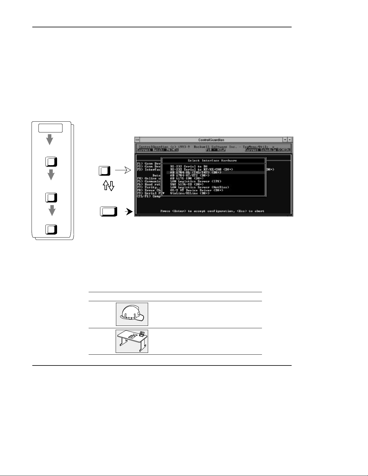
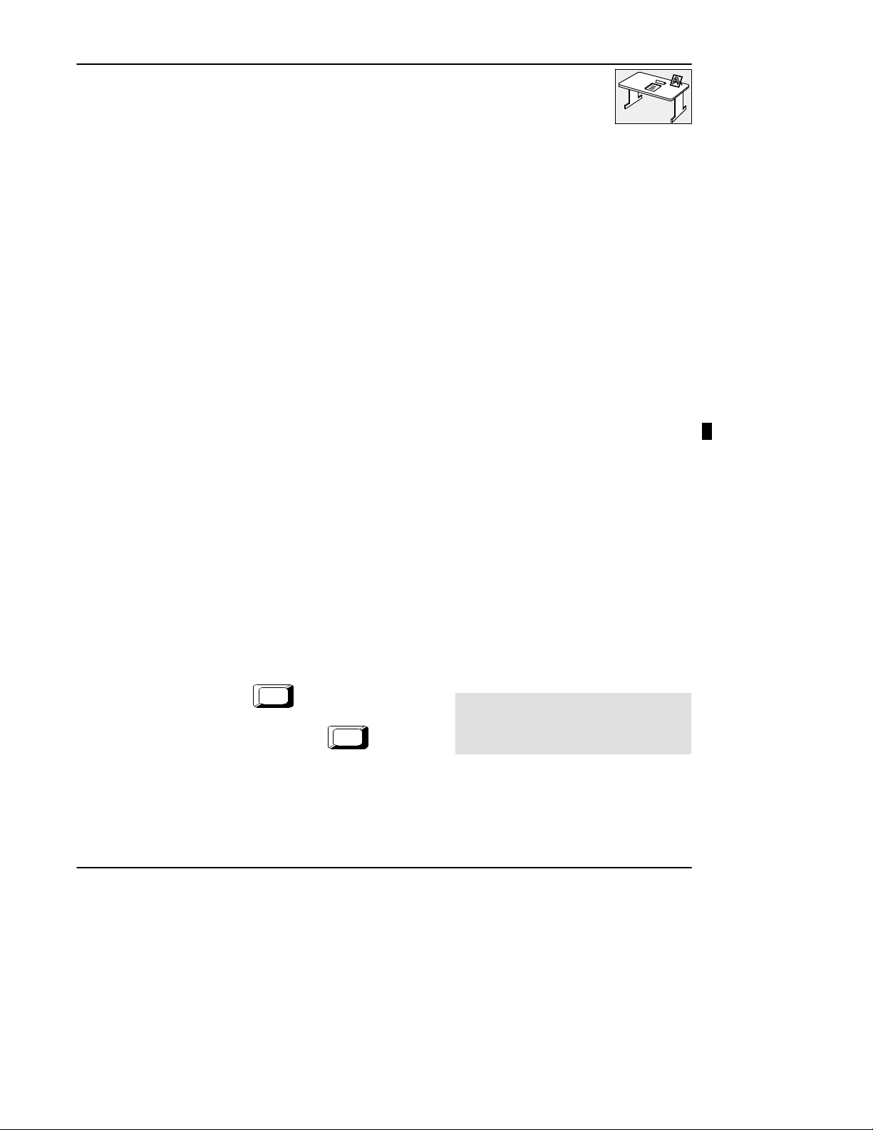
This manual uses pictures of keys and/or screens to represent the actual keys you
press or screens you see. For example, in the procedure to configure the parameters
for an Allen-Bradley 1784-KL communication device, you see:
Configure Program
Parameters
F8
Communication
Hardware
F1
Create
Ins
6 2 0
¬
-
®
F3
Press
Use the keys
to select your
communication device
Press
accept the configuration.
Enter
to
The procedure shows that you start on the ControlGuardian main menu and then
press [F8]. Then press [F1] and then, press [Ins]. You see the screen to the right of
the key sequence. The circled numbers are for the tasks you perform once you have
accessed the screen.
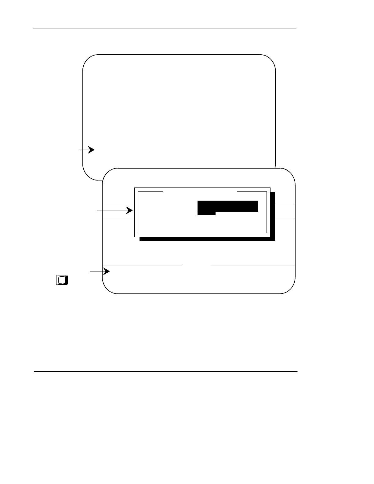
In addition, the icons on the first page of every chapter help guide you to the
sections you need the most.
This icon: Represents sections a:
user on the plant floor might need
system administrator might need
preface-i
Page 5

ControlGuardian User’s Guide
Preface
Commonly Used Terms
Table P.A defines terms common to ControlGuardian.
T ableP.A
Common Terms
This term: Represents this concept:
upload Access a PLC processor and save a copy of the program and data
download Restore a specified file to a specified processor. Forexample,when
master
file
library
production
file
library
back up Keep a copy of the current file before replacing that file with an
table in a specified directory and archive file. For example, when you
upload a production file, you copy a file running in a processor to the
production library.
you download a master file, you copy the specified file to a specified
processor so the processor can begin running that file.
The approved version of a processor file that you want to archive.
the collection of program files and data table files that make
the processor file
the directory where you store all master files for a family of
processors; there is one library for PLC-2 files, one for
PLC-3 files, one for PLC-5 files, one for PanelView
1200 files, and one for SLC 500 files.
The processor file that you want to compare to a master file.
the collection of program files and data table files that make
the processor file
the directory where you store all production files for a family
of processors; there is one library for PLC-2 files, one for
PLC-3 files, one for PLC-5 files, one for PanelView
1200 files, and one for SLC 500 files.
updated version. For example, when you store a new version of a
master file, ControlGuardian copies (backs up) the current version to a
backup directory.
preface-ii
Page 6

Table of Contents
1 Quick Start 1-1. . . . . . . . . . . . . . . . . . . . . . . . . . . . . . . . . . . . . . . . . . . . . . . . . . . . . . . . . . .
Introducing ControlGuardian Software 1-1. . . . . . . . . . . . . . . . . . . . . . . . . . . . . . . . . . .
Setting Up Your System Communications Configuration 1-2. . . . . . . . . . . . . . . . . . . . .
Using the Main Menu 1-4. . . . . . . . . . . . . . . . . . . . . . . . . . . . . . . . . . . . . . . . . . . . . . . . .
Navigating through the Software 1-4. . . . . . . . . . . . . . . . . . . . . . . . . . . . . . . . . . . .
Function Keys 1-5. . . . . . . . . . . . . . . . . . . . . . . . . . . . . . . . . . . . . . . . . . . . . . . . . . .
Selecting Files 1-6. . . . . . . . . . . . . . . . . . . . . . . . . . . . . . . . . . . . . . . . . . . . . . . . . . . . . .
Disk File Extensions 1-7. . . . . . . . . . . . . . . . . . . . . . . . . . . . . . . . . . . . . . . . . . . . . . . . . .
Starting ControlGuardian Software for the First Time 1-8. . . . . . . . . . . . . . . . . . . . . . .
Identifying Which Tasks You Need 1-10. . . . . . . . . . . . . . . . . . . . . . . . . . . . . . . . . . . . . .
Completing System Administration Tasks 1-10. . . . . . . . . . . . . . . . . . . . . . . . . . . . .
Plant Floor Operations 1-11. . . . . . . . . . . . . . . . . . . . . . . . . . . . . . . . . . . . . . . . . . . .
2 Installing and Starting the Software 2-1. . . . . . . . . . . . . . . . . . . . . . . . . . . . . . . . . . . .
Chapter Objectives 2-1. . . . . . . . . . . . . . . . . . . . . . . . . . . . . . . . . . . . . . . . . . . . . . . . . . .
Where to Start 2-1. . . . . . . . . . . . . . . . . . . . . . . . . . . . . . . . . . . . . . . . . . . . . . . . . . . . . .
Installing the Software 2-1. . . . . . . . . . . . . . . . . . . . . . . . . . . . . . . . . . . . . . . . . . . . . . . .
Starting the Software 2-3. . . . . . . . . . . . . . . . . . . . . . . . . . . . . . . . . . . . . . . . . . . . . . . . .
Using the DOS Command Line 2-3. . . . . . . . . . . . . . . . . . . . . . . . . . . . . . . . . . . . . . . . .
Using ControlGuardian in a Windows Environment 2-5. . . . . . . . . . . . . . . . . . . . . . . . .
Recommendations for CONFIG.SYS 2-6. . . . . . . . . . . . . . . . . . . . . . . . . . . . . . . . .
Creating a .PIF File 2-8. . . . . . . . . . . . . . . . . . . . . . . . . . . . . . . . . . . . . . . . . . . . . . .
Starting the Software in Windows 2-9. . . . . . . . . . . . . . . . . . . . . . . . . . . . . . . . . . .
Exiting the Software 2-11. . . . . . . . . . . . . . . . . . . . . . . . . . . . . . . . . . . . . . . . . . . . . . . . . .
Table of Contents
3 Configuring Communications 3-1. . . . . . . . . . . . . . . . . . . . . . . . . . . . . . . . . . . . . . . . . .
Chapter Objectives 3-1. . . . . . . . . . . . . . . . . . . . . . . . . . . . . . . . . . . . . . . . . . . . . . . . . . .
Configuring Communication Hardware 3-2. . . . . . . . . . . . . . . . . . . . . . . . . . . . . . . . . . .
Configuring Program Operational Parameters 3-4. . . . . . . . . . . . . . . . . . . . . . . . . . . . . .
Configuring the RS-232 Serial to DH 3-6. . . . . . . . . . . . . . . . . . . . . . . . . . . . . . . . . . . .
Configuring the RS-232 Serial to KF/KE/CH0 (DH+) 3-7. . . . . . . . . . . . . . . . . . . . . . .
Configuring 1784-KL (DH+) 3-9. . . . . . . . . . . . . . . . . . . . . . . . . . . . . . . . . . . . . . . . . . .
Configuring a 1784-KT/KT2 (DH+) 3-10. . . . . . . . . . . . . . . . . . . . . . . . . . . . . . . . . . . . .
Configuring a 6171-IDH (DH+) 3-12. . . . . . . . . . . . . . . . . . . . . . . . . . . . . . . . . . . . . . . .
Configuring a LAN Logistics Server (IPX) 3-13. . . . . . . . . . . . . . . . . . . . . . . . . . . . . . . .
Configuring a Sutherland Schultz 5136-SD Board (DH+) 3-14. . . . . . . . . . . . . . . . . . . .
Configuring a LAN Logistics Server (NetBios) 3-15. . . . . . . . . . . . . . . . . . . . . . . . . . . .
Configuring an OS/2âKT Device Driver (DH+) 3-16. . . . . . . . . . . . . . . . . . . . . . . . . . .
Configuring a WinLinx/RSLinx Driver (DH+) 3-17. . . . . . . . . . . . . . . . . . . . . . . . . . . . .
i
Page 7

ControlGuardian User’s Guide
Preface
Configuring an Ethernet Device 3-18. . . . . . . . . . . . . . . . . . . . . . . . . . . . . . . . . . . . . . . .
Configuring a 1784-KTX/KTXD (DH+) 3-20. . . . . . . . . . . . . . . . . . . . . . . . . . . . . . . . . .
Configuring a 1784-PCMK (DH+) 3-21. . . . . . . . . . . . . . . . . . . . . . . . . . . . . . . . . . . . . .
Configuring a Serial Port to A-B 1747-PIC 3-23.. . . . . . . . . . . . . . . . . . . . . . . . . . . . . . .
Configuring an A-B 1784-KT/KT2 with a S5-103 Cable 3-24. . . . . . . . . . . . . . . . . . . . .
Configuring an A-B 1784-KL with a S5-103 Cable 3-25. . . . . . . . . . . . . . . . . . . . . . . . .
Configuring an A-B 1784-KR 3-26. . . . . . . . . . . . . . . . . . . . . . . . . . . . . . . . . . . . . . . . . .
Configuring an A-B 1784-PCMK with a S5-104 Cable 3-27. . . . . . . . . . . . . . . . . . . . . .
Configuring a 1784-KTX/KTXD on DH485 3-28. . . . . . . . . . . . . . . . . . . . . . . . . . . . . . .
Configuring an A-B 1770-KF3, 1747-KE, 5/03, 5/04 Ch 0 3-29. . . . . . . . . . . . . . . . . . .
Configuring an A-B 1784-KT/KT2 to DH485 3-30. . . . . . . . . . . . . . . . . . . . . . . . . . . . . .
Configuring a A-B 1784-KL to DH485 3-31. . . . . . . . . . . . . . . . . . . . . . . . . . . . . . . . . . .
Configuring an A-B 1784-KTX/KTXD to DH485 3-32. . . . . . . . . . . . . . . . . . . . . . . . . .
Configuring an A-B 1784-PCMK to DH485 3-33. . . . . . . . . . . . . . . . . . . . . . . . . . . . . . .
Configuring a Sutherland Schultz 5136-SD/SD2 to DH485 3-34. . . . . . . . . . . . . . . . . . .
Configuring a WinLinx/RSLinx Driver to DH485 3-35. . . . . . . . . . . . . . . . . . . . . . . . . .
Configuring an A-B Ethernet to DH485 3-36. . . . . . . . . . . . . . . . . . . . . . . . . . . . . . . . . .
Configuring a LAN Logistics Server to DH485 (IPX) 3-37. . . . . . . . . . . . . . . . . . . . . . .
Configuring a LAN Logistics Server to DH485 (NetBios) 3-38. . . . . . . . . . . . . . . . . . . .
Modifying a Communication Device Configuration File 3-39. . . . . . . . . . . . . . . . . . . . .
4 Inserting Files into the Master Library 4-1. . . . . . . . . . . . . . . . . . . . . . . . . . . . . . . . . .
Chapter Objectives 4-1. . . . . . . . . . . . . . . . . . . . . . . . . . . . . . . . . . . . . . . . . . . . . . . . . . .
Understanding the Master Library 4-1. . . . . . . . . . . . . . . . . . . . . . . . . . . . . . . . . . . . . . .
Approving a Master File 4-1. . . . . . . . . . . . . . . . . . . . . . . . . . . . . . . . . . . . . . . . . . .
Inserting PLC Files into the Master Library 4-3.. . . . . . . . . . . . . . . . . . . . . . . . . . . . . .
Selecting PLC-5 Files Types 4-4. . . . . . . . . . . . . . . . . . . . . . . . . . . . . . . . . . . . . . . .
Inserting PanelView 1200 Application Files into the Master Library 4-6. . . . . . . . . . . .
Inserting PLC-2 and PLC-3 Documentation Files into the Master Library 4-7. . . . . . .
Inserting SLC 500 Files into the Master Library 4-8. . . . . . . . . . . . . . . . . . . . . . . . . . . .
Downloading Files from the Master Library 4-9. . . . . . . . . . . . . . . . . . . . . . . . . . . . . . .
5 Comparing Files 5-1. . . . . . . . . . . . . . . . . . . . . . . . . . . . . . . . . . . . . . . . . . . . . . . . . . . . . .
Chapter Objectives 5-1. . . . . . . . . . . . . . . . . . . . . . . . . . . . . . . . . . . . . . . . . . . . . . . . . . .
Using Single Action 5-1. . . . . . . . . . . . . . . . . . . . . . . . . . . . . . . . . . . . . . . . . . . . . . . . . .
Comparing Parts of a Processor Memory File 5-3. . . . . . . . . . . . . . . . . . . . . . . . . . . . . .
Uploading Parts of a Processor Memory File 5-4. . . . . . . . . . . . . . . . . . . . . . . . . . . . . .
Creating a Batch File 5-5. . . . . . . . . . . . . . . . . . . . . . . . . . . . . . . . . . . . . . . . . . . . . . . . .
Changing Parameter Defaults 5-7. . . . . . . . . . . . . . . . . . . . . . . . . . . . . . . . . . . . . . .
Duplicating Batch Files 5-7. . . . . . . . . . . . . . . . . . . . . . . . . . . . . . . . . . . . . . . . . . . .
Modifying a Batch File 5-8. . . . . . . . . . . . . . . . . . . . . . . . . . . . . . . . . . . . . . . . . . . . . . .
Performing an Auto Batch 5-9. . . . . . . . . . . . . . . . . . . . . . . . . . . . . . . . . . . . . . . . . . . . .
ii
Page 8

Table of Contents
Running a Batch File 5-11.. . . . . . . . . . . . . . . . . . . . . . . . . . . . . . . . . . . . . . . . . . . . . . . .
Creating a Schedule File 5-12. . . . . . . . . . . . . . . . . . . . . . . . . . . . . . . . . . . . . . . . . . . . . .
Modifying Schedule Files 5-14. . . . . . . . . . . . . . . . . . . . . . . . . . . . . . . . . . . . . . . . . . . . .
Running a Schedule File 5-15. . . . . . . . . . . . . . . . . . . . . . . . . . . . . . . . . . . . . . . . . . . . . .
6 Backing Up Files 6-1. . . . . . . . . . . . . . . . . . . . . . . . . . . . . . . . . . . . . . . . . . . . . . . . . . . . . .
Chapter Objectives 6-1. . . . . . . . . . . . . . . . . . . . . . . . . . . . . . . . . . . . . . . . . . . . . . . . . . .
Backing Up Master Files 6-1. . . . . . . . . . . . . . . . . . . . . . . . . . . . . . . . . . . . . . . . . . . . . .
Understanding Master File Backup Generations 6-1. . . . . . . . . . . . . . . . . . . . . . . .
Specifying Master Directory Paths 6-3. . . . . . . . . . . . . . . . . . . . . . . . . . . . . . . . . . . . . .
Backing Up Production Files 6-5. . . . . . . . . . . . . . . . . . . . . . . . . . . . . . . . . . . . . . . . . . .
Specifying the Number of Production File Backups 6-6. . . . . . . . . . . . . . . . . . . . . . . . .
7 Managing Files 7-1. . . . . . . . . . . . . . . . . . . . . . . . . . . . . . . . . . . . . . . . . . . . . . . . . . . . . . .
Chapter Objectives 7-1. . . . . . . . . . . . . . . . . . . . . . . . . . . . . . . . . . . . . . . . . . . . . . . . . . .
Using the File Utilities Screen 7-1. . . . . . . . . . . . . . . . . . . . . . . . . . . . . . . . . . . . . . . . . .
Copying Files 7-3. . . . . . . . . . . . . . . . . . . . . . . . . . . . . . . . . . . . . . . . . . . . . . . . . . . . . . .
Renaming Files 7-4. . . . . . . . . . . . . . . . . . . . . . . . . . . . . . . . . . . . . . . . . . . . . . . . . . . . . .
Deleting Files 7-5. . . . . . . . . . . . . . . . . . . . . . . . . . . . . . . . . . . . . . . . . . . . . . . . . . . . . . .
Backing Up Files to a Floppy Disk 7-6. . . . . . . . . . . . . . . . . . . . . . . . . . . . . . . . . . . . . .
Restoring Files 7-7. . . . . . . . . . . . . . . . . . . . . . . . . . . . . . . . . . . . . . . . . . . . . . . . . . . . . .
Formatting Disks for Backup 7-8. . . . . . . . . . . . . . . . . . . . . . . . . . . . . . . . . . . . . . . . . . .
Calculating the Number of Disks for Backup 7-9. . . . . . . . . . . . . . . . . . . . . . . . . . . . . .
8 Using Network Diagnostics 8-1. . . . . . . . . . . . . . . . . . . . . . . . . . . . . . . . . . . . . . . . . . . .
Chapter Objectives 8-1. . . . . . . . . . . . . . . . . . . . . . . . . . . . . . . . . . . . . . . . . . . . . . . . . . .
Accessing Network Diagnostics 8-1. . . . . . . . . . . . . . . . . . . . . . . . . . . . . . . . . . . . . . . . .
Using WHO Active 8-2. . . . . . . . . . . . . . . . . . . . . . . . . . . . . . . . . . . . . . . . . . . . . . . . . .
Getting Station Diagnostics 8-5. . . . . . . . . . . . . . . . . . . . . . . . . . . . . . . . . . . . . . . . . . . .
Using the Timing Test 8-10. . . . . . . . . . . . . . . . . . . . . . . . . . . . . . . . . . . . . . . . . . . . . . . .
9 Configuring Security 9-1. . . . . . . . . . . . . . . . . . . . . . . . . . . . . . . . . . . . . . . . . . . . . . . . . .
Chapter Objectives 9-1. . . . . . . . . . . . . . . . . . . . . . . . . . . . . . . . . . . . . . . . . . . . . . . . . . .
Using the Security Options 9-1. . . . . . . . . . . . . . . . . . . . . . . . . . . . . . . . . . . . . . . . . . . .
System Security 9-1. . . . . . . . . . . . . . . . . . . . . . . . . . . . . . . . . . . . . . . . . . . . . . . . . .
User Security 9-2. . . . . . . . . . . . . . . . . . . . . . . . . . . . . . . . . . . . . . . . . . . . . . . . . . . .
Setting Up System Security 9-3. . . . . . . . . . . . . . . . . . . . . . . . . . . . . . . . . . . . . . . . . . . .
Using Disk Logging 9-4. . . . . . . . . . . . . . . . . . . . . . . . . . . . . . . . . . . . . . . . . . . . . . . . . .
Specifying a User Log Path 9-5.. . . . . . . . . . . . . . . . . . . . . . . . . . . . . . . . . . . . . . .
Printing a User Log 9-6. . . . . . . . . . . . . . . . . . . . . . . . . . . . . . . . . . . . . . . . . . . . . . .
User Log Reports 9-7. . . . . . . . . . . . . . . . . . . . . . . . . . . . . . . . . . . . . . . . . . . . . . . .
Clearing the User Log 9-8. . . . . . . . . . . . . . . . . . . . . . . . . . . . . . . . . . . . . . . . . . . . .
iii
Page 9

ControlGuardian User’s Guide
Preface
Defining a New Master Password 9-9. . . . . . . . . . . . . . . . . . . . . . . . . . . . . . . . . . . . . . .
Setting Up User Security Parameters 9-9. . . . . . . . . . . . . . . . . . . . . . . . . . . . . . . . . . . . .
Assigning User Names, Passwords, and Access Rights 9-10. . . . . . . . . . . . . . . . . . .
Changing User Passwords 9-12.. . . . . . . . . . . . . . . . . . . . . . . . . . . . . . . . . . . . . . . . . . . .
Adding and Deleting Access Rights 9-13. . . . . . . . . . . . . . . . . . . . . . . . . . . . . . . . . . . . .
10 Generating and Printing Reports 10-1. . . . . . . . . . . . . . . . . . . . . . . . . . . . . . . . . . . . . . .
Chapter Objectives 10-1.. . . . . . . . . . . . . . . . . . . . . . . . . . . . . . . . . . . . . . . . . . . . . . . . . .
Generating Reports 10-1. . . . . . . . . . . . . . . . . . . . . . . . . . . . . . . . . . . . . . . . . . . . . . . . . . .
Comparison Reports 10-2. . . . . . . . . . . . . . . . . . . . . . . . . . . . . . . . . . . . . . . . . . . . . .
Schedule Log Reports 10-4. . . . . . . . . . . . . . . . . . . . . . . . . . . . . . . . . . . . . . . . . . . . .
Batch Log Reports 10-4. . . . . . . . . . . . . . . . . . . . . . . . . . . . . . . . . . . . . . . . . . . . . . .
User Log Reports 10-5. . . . . . . . . . . . . . . . . . . . . . . . . . . . . . . . . . . . . . . . . . . . . . . .
Viewing a Report 10-6. . . . . . . . . . . . . . . . . . . . . . . . . . . . . . . . . . . . . . . . . . . . . . . . . . . .
Configuring Reports 10-7. . . . . . . . . . . . . . . . . . . . . . . . . . . . . . . . . . . . . . . . . . . . . . . . . .
Printing Reports 10-12. . . . . . . . . . . . . . . . . . . . . . . . . . . . . . . . . . . . . . . . . . . . . . . . . . . . .
Printing Reports Using .AF5 Format Files 10-13. . . . . . . . . . . . . . . . . . . . . . . . . . . . .
Creating or Modifying a Printer Template 10-14. . . . . . . . . . . . . . . . . . . . . . . . . . . . .
Saving a Report Configuration 10-16. . . . . . . . . . . . . . . . . . . . . . . . . . . . . . . . . . . . . . . . .
Loading a New Report Configuration 10-17. . . . . . . . . . . . . . . . . . . . . . . . . . . . . . . . . . . .
A Specifications A-1. . . . . . . . . . . . . . . . . . . . . . . . . . . . . . . . . . . . . . . . . . . . . . . . . . . . . . . .
B Cable Connections B-1. . . . . . . . . . . . . . . . . . . . . . . . . . . . . . . . . . . . . . . . . . . . . . . . . . . .
iv
Page 10
1 Quick Start
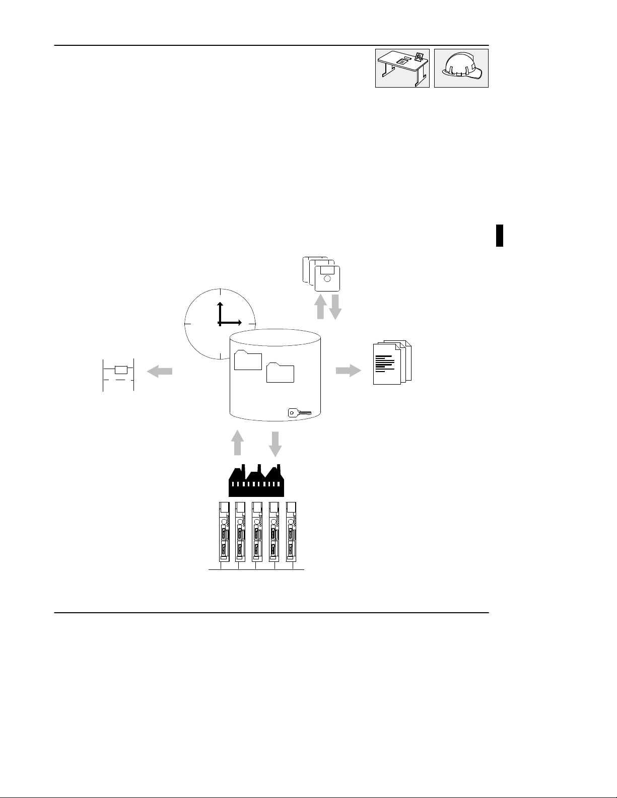
Introducing ControlGuardian Software
ControlGuardianäsoftware enables you to manage, verify,and access programs and
documentation for devices communicating over Data Highway, Data Highway
Plusä, Ethernet, and serial networks. ControlGuardian software is compatible with
Allen-Bradley PLC-5â, PLC-3Ò, PLC-2Ò, and SLC 500Ôprogrammable
controllers and PanelViewÔ1200 operator terminals.
" central master library
Quick Start
" offsite archive
[
] ()
" application solutions
" automatic change
detection
" connectivity
Use this chapter to start ControlGuardian for the first time and to familiarize
yourself with the conventions and functions the software uses.
" security
" reports
" version control
1-1
Page 11
ControlGuardian User’s Guide
Preface
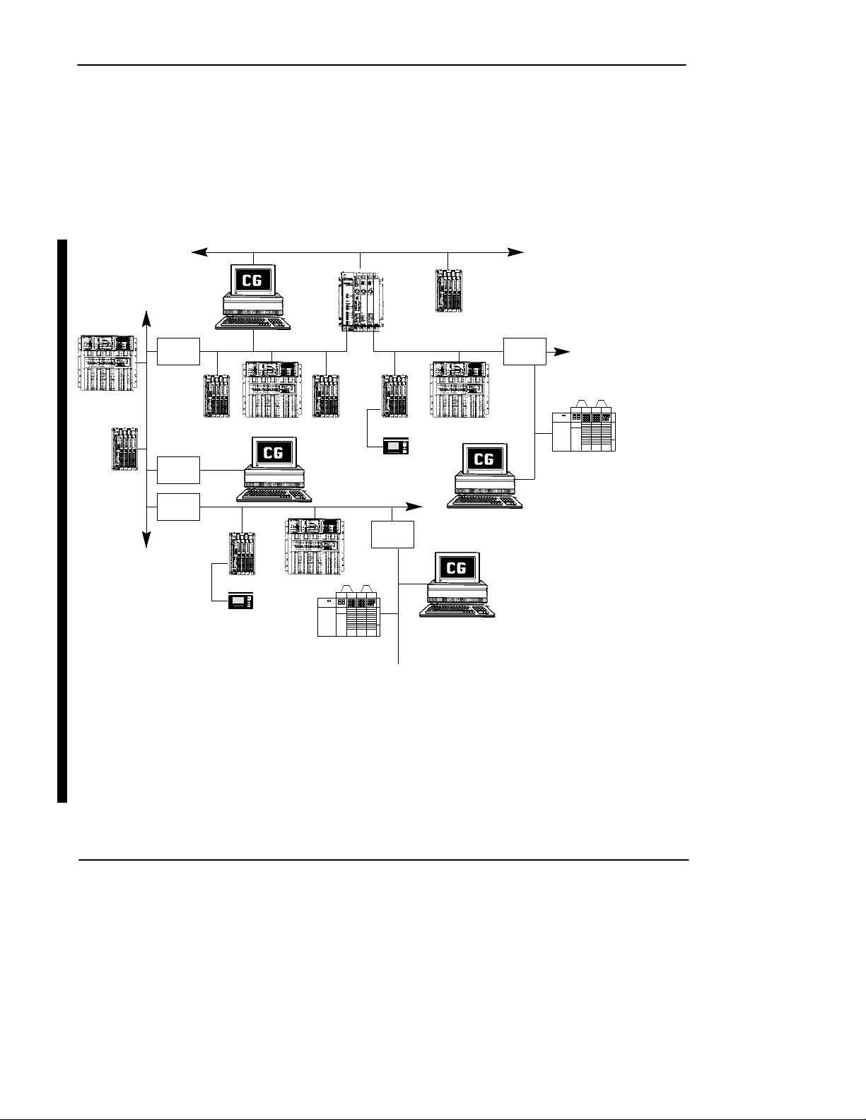
Setting Up Your System Communications Configuration
Figure 1.1 shows the different ways you can configure ControlGuardian software in
Allen-Bradley control networks.
Figure 1.1
ControlGuardian Fits into Your Existing Control Network
Ethernet TCP/IP
DH
1785
KA
PLC-3
1770
PLC-2
DH+ communication cards
1784-T47 1784-KL/B
DOS-based 1784-KT
computer 1784-KTX, -KTXD
microchannel 1784-KT2
computer
PCMCIA 1784-PCMK
KF2/B
1785
KA
DH
PanelView 1200
DH+ link DH+ link
PLC-5 PLC-3PLC-2PLC-3PLC-5
PanelView 1200
DH+
1785
KA5
PLC-3PLC-5
. .
.
SLC 500
DH485 link
Ethernet communication cards
DOS-based 6628-A5
computer
microchannel 6628-A7
computer
PLC-5/E
1785
KA5
DH485 link
. .
.
SLC 500
1-2
Page 12
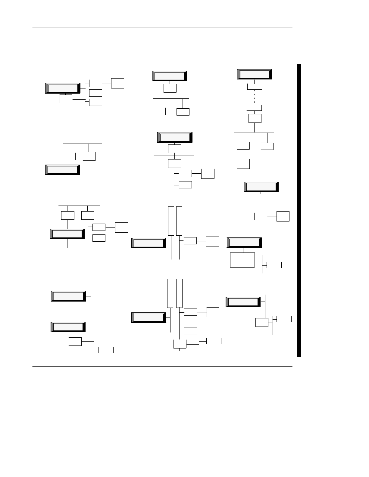
Select from a wide range of system architectures (Figure 1.2).
Figure 1.2
ControlGuardian Building Blocks
local DH+ link
DH+
RIO
ControlGuardian
1770
KF2/B
PLC-5
PLC-3
PLC-2
DH+
DH+ link to DH gateway
DH
PLC-3
ControlGuardian
remote bridging
DH DH
1785
KA
ControlGuardian
DH+
1785
KA
1785
KA
DH+
DH+
PLC-5
PLC-3
RIO
local Ethernet link remote Ethernet link (gateway)
Ethernet TCP/IP
ControlGuardian
PLC-5/E
1770-KF3/1747-KE link
ControlGuardian
1770
DH485
PIC
SLC 500
local DH link
Panel
View
DH
DH link to DH+
gateway
DH
DH485
Pyramid Integratorärouting
Panel
View
ControlGuardian
ControlGuardian
Ethernet TCP/IP
ControlGuardian
1770
KF2/B
PLC-2 PLC-3
6200 formatonly
ControlGuardian
1770
KF2/B
1785
KA
PLC-5
PLC-3
DH+
5
5
1
1
3
3
0
0
R
K
M
A
DH+ DH+
5
5
1
8
3
2
0
0
K
E
A
I
1785
KA5
DH+
PLC-5
PLC-5
PLC-3
PLC-2
RIO
RIO
DH485
RIO
Panel
View
Panel
View
SLC 500
Panel
View
remote DH+ link
ControlGuardian
modem
modem
1770
KF2/B
DH+
PLC-5 PLC-3
RIO
Panel
View
direct serial
ControlGuardian
local DH485 link
ControlGuardian
1770-KF3
or
1747-KE
DH+ link to DH485 gateway
ControlGuardian
PLC-5
DH485
DH485
1785
KA5
Quick Start
RS-232
RIO
SLC 500
DH+
DH485
Panel
View
SLC 500
1-3
Page 13
ControlGuardian User’s Guide
Preface
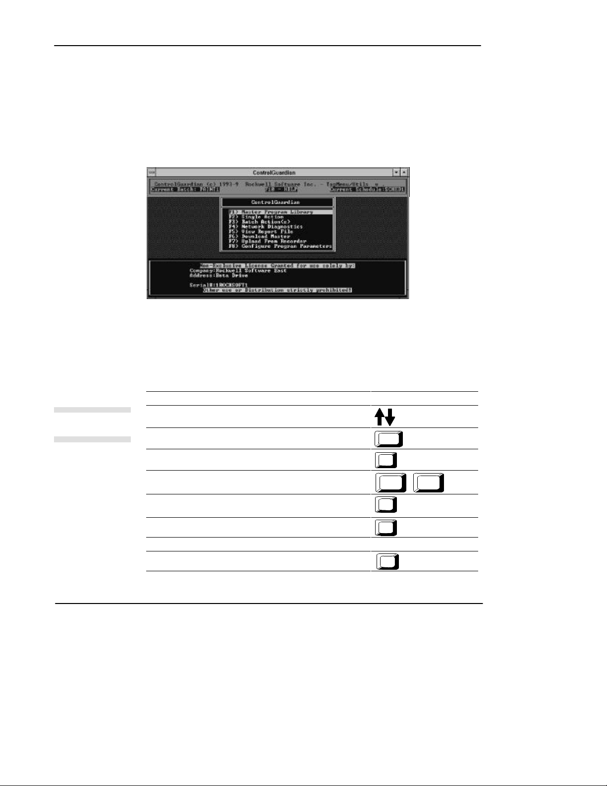
Using the Main Menu
After you start the ControlGuardian software, it displays the main menu screen
(Figure 1.3).
Figure 1.3
ControlGuardian Main Menu
Navigating through the Software
6 2 0
Special keys
1-4
Table 1.A lists the navigational keys you can use.
T able1.A
Navigational Keys for Use with ControlGuardian Software
If you want to: Press this key:
Highlight or select an option
Highlight the first option in the list
Highlight the last option in the list
Page through multiple screens
Go to the previous menu or exit the software from the main menu
Abort current entry
Insert a selected file into a directory
Select an option on the screen corresponding function key
Display online help
Home
End
Page
Up
Esc
Ins
F10
arrow key(s)
Page
Down
Page 14
Function Keys
Master
Program
Library
Single
Action
Batch
Action(s)
Network
Diagnostics
V
iew
Report
File
Download
Master
Upload
from
Recorder
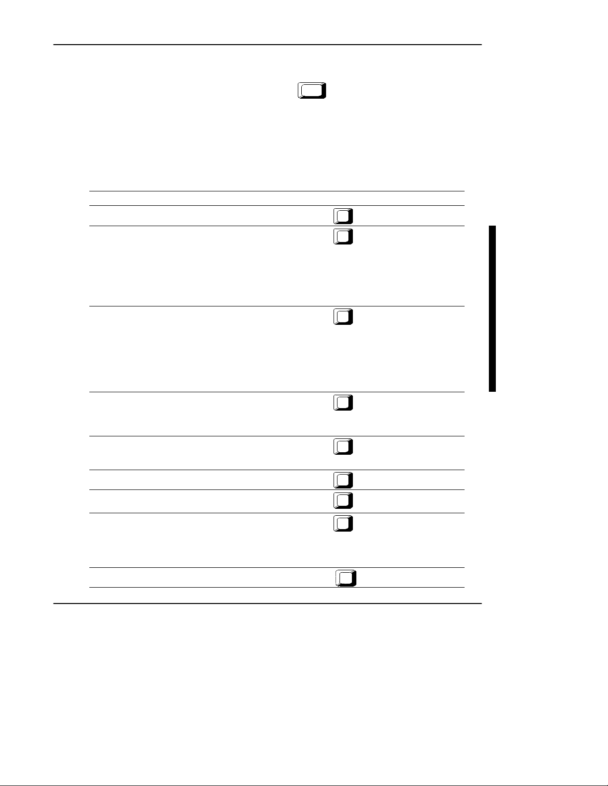
If you want to: Press this key:
Retrieve an existing master file or select a directory
Quick Start
Some menus let you make selections by pressing the letter that is capitalized in the
selection you want and then pressing
Enter
.
The function keys differ for each screen in the software. Table 1.B describes the
function keys on the main menu.
T able1.B
Function Keys on the Main Menu
F1
Perform a single action.
Choose from one of the following actions:
· Compareonly · Upload and compare
· Retrieveandcompare · Upload only
· Partialupload · Upload and binary compare
· Partialuploadandcompare · Upload and smart compare
· Retrieveonly
Perform a batch action.
Choose from one of the following actions:
· Editbatch · View batch log
· Editschedule · Viewschedulelog
· Runbatch
· Runschedule
Schedule the time, day,week,ormonthwhenyouwantthebatch
file to execute.
Access diagnostic functions:
· WHOactive
· WHOListen
· DiagnosticLoopTest
Display a report file on the screen
Note: To view the file on the screen you must select a filename with
a .TXT ,.Lxx, or .ERR extension.
Download a master file to a specified PLC address
Upload/download your PLC-2 and PLC-3 programs to and from a
SA/SB cassette cartridge recorder
Access the following configuration areas:
· CommunicationHardware
· Report
· ProgramOperationalParameters
· Security
Access online help
F2
F3
F4
F5
F6
F7
F10
Configure Program
Parameters
Help
F8
1-5
Page 15
ControlGuardian User’s Guide
Preface
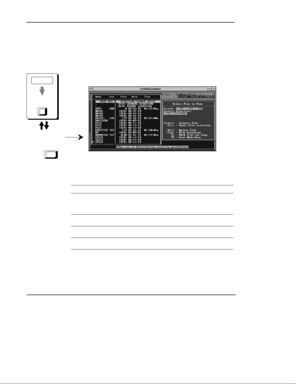
Selecting Files
ControlGuardian displays a file directory whenever you need to select a file or
directory. The example below shows the file directory screen when you select the
master program library option.
Main Menu
Master Program
Library
F1
¬
Use
select a file or directory.
keys to
2 0
-
Press
Enter
T able1.C
Directory Selections
If you want to: Select:
Create a new directory or change the default to another disk drive
or directory.
The software will then prompt you for a DOS directory specification
and create the directory if it does not already exist.
Perform a refresh on the current directory. .
Move up one directory level. ..
Move down one specific directory. directory name
Make New
Directory/Change Drive
Current Directory
Parent Directory
<DIR>
1-6
Page 16

Disk File Extensions
ControlGuardian assigns file extensions to disk files based on the type of
information the files contain. Table 1.D lists these file extensions.
T able1.D
Disk File Extensions
Quick Start
File type: Uses this
PLC-5 archive files .AF5
PLC-3 archive files .VDI
PLC-2 archive files .LAD, .PRF
PanelView1200 archivefiles .APL
Report files:
Comparison
Batch log
Schedule log
User log
Last error
Configuration format
Titlepage
extension:
.X5
.ACH
.PR1, .DA1
.TXT
.LOG
.Lxx
user specified
.ERR
.RCF
.TTL
1-7
Page 17
ControlGuardian User’s Guide
Preface
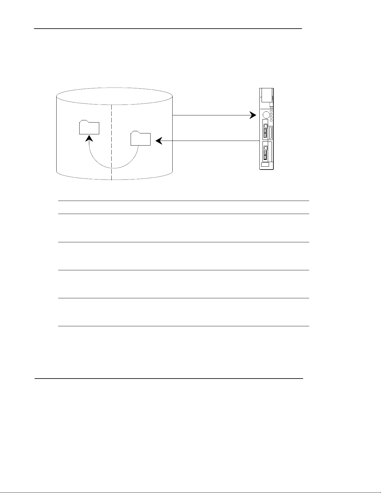
Starting ControlGuardian Software for the First Time
Use the following steps to get ControlGuardian software ready to support your
processor system.
productionmaster
WHO
Â
¬ and Á
upload only
Ã
insert master
In this step: You:
À configurecommunicationhardware Selecttheappropriatecommunicationcardandsetthe
Á use WHO Use WHO to select a processor. Selectjustoneprocessorforthe
 uploadonly Upload the processor memory file from one processor. Usethe
à insertmaster Since this is the first upload from a processor,assumethatthe
communication parameters so the programming terminal can
communicate with the processor. Forinformationontheavailable
communication hardware, see chapter 3.
first upload action.
For information on using WHO, see chapter 8. For information on
the available communication options, see chapter 3.
single action function to select upload only. Thisplacesthe
processor memory file in the production directory.
For more information, see chapter 5.
processor memory file is the master you want to start using with
ControlGuardian. Insert the production file into the master directory.
For more information, see chapter 4.
1-8
Now you have a master file that you can compare to other files. If you have several
processor memory files to upload, create a batch file to upload the remaining files.
The parameters you set for the above single upload become the defaults for the
batch edit function. Just change the processor for each upload action in the
batch file.
Page 18

Quick Start
Once you get your initial master files ready, you can begin running and scheduling
upload and compare actions. One place to start is to make a copy of the batch file
you used to insert the initial production files. Then modify the actions from upload
to upload and compare. That gives you a batch file that is ready to upload and
compare all the processors in your system. For more information about editing
batch files, see chapter 5.
1-9
Page 19

ControlGuardian User’s Guide
Preface
Identifying Which Tasks You Need
Configure ControlGuardian user parameters to fit your tasks. For example, some
users may need to access security parameters, others may not.
Completing System Administration Tasks
To assist you in installing, starting, and configuring the software, see these
main sections:
Installing the Software 2-1. . . . . . . . .
Using the DOS Command Line 2-3. .
Using ControlGuardian in a
Windows Environment 2-5. . . . . . .
Configuring Communication
Hardware 3-1. . . . . . . . . . . . . . . . . .
Configuring Program
Operational Parameters 3-4. . . . . . .
Backing Up Master Files 6-1. . . . . . .
Using the Security Options 9-1. . . . . .
Advanced Activities
1-10
Backing Up Files to a Floppy 7-6. . . .
Using Network Diagnostics 8-1. . . . .
Using the Timing Test 8-10. . . . . . . . .
Using Disk Logging 9-4. . . . . . . . . . .
Defining a New Master Password 9-9
Setting Up User
Security Parameters 9-9. . . . . . . . . .
Configuring Reports 10-7. . . . . . . . . . .
Printing Reports 10-12. . . . . . . . . . . . . .
Page 20

Plant Floor Operations
To assist you in running the software, see these main sections:
Using the Main Menu 1-4. . . . . . . . . .
Understanding the Master Library 4-1
Downloading Files from the
Master Library 4-9. . . . . . . . . . . . . .
Using Single Action 5-1. . . . . . . . . . .
Creating a Batch Compare File 5-5. .
Creating a Schedule File 5-12. . . . . . .
Generating Reports 10-1. . . . . . . . . . . .
Viewing a Report 10-6. . . . . . . . . . . . .
Quick Start
1-11
Page 21
Installing and Starting the Software
2 Installing and Starting the Software
Chapter Objectives
Use the information in this chapter to install the software and configure the software
for use in DOS and Windowsâ. For information on system specifications, see
appendix A.
Where to Start
To use ControlGuardian software you need a working knowledge of:
· Allen-Bradley PLC-2, PLC-3, PLC-5, or SLC 500 processors
· PanelView 1200 pass through
· your programming terminal
· your programming software
· A.I. series software
· 6200 software
Installing the Software
At the DOS prompt, insert the disk labeled “Disk 1 of n” into the disk drive, where n
is equal to the total number of disks. Type:
Enter
A:
INSTALL C:
Enter
a: is the drive where you insert the disk.
c: is any destination hard-disk for the
ControlGuardian software.
2-1
Page 22
ControlGuardian User’s Guide
Preface
Press any key.
¬
Enter your companyname
-
andaddress. You can find
the serial number on the
diskette labels. Serial
numbers are 10 numeric
characters in length.
You see:
Rockwell Software, Inc., Copyright 1996, All rights reserved.
Rockwell Software, Inc. grants you a license to install and
use this software on a single processing unit. You are not
licensed to install the software on more than one processing unit
or to distribute it in any way. However, if you have purchased a
Network license or a Site license from Rockwell Software, it will
specify any additional installation rights you may have. Registered
customers receive support and updates. To register your software,
return the enclosed registration card as soon as possible.
****************************************************************
* WARNING *
* THIS SOFTWARE IS PROTECTED UNDER THE COPYRIGHT LAWS OF THE *
* UNITED STATES. UNAUTHORIZED REPRODUCTION OF COPYRIGHTED *
* SOFTWARE VIOLATES U.S. COPYRIGHT LAWS. CRIMINAL PENALTIES *
* MAY INCLUDE FINES OR IMPRISONMENT. *
****************************************************************
[press any key to start installation]
Contents: ControlGuardian Archiving Software for Programmable Devices
Catalog
Part Num
Release
Product Registration Information
Company Name:
Address:
:
Serial Number:
®
When you are finished,
press
F9
2-2
Instructions
Enter product registration info and press F9
Page 23

Starting the Software
Use Table 2.A to select a method for starting your management software.
T able2.A
Methods to Start the Software
If you want to: Choose this method: On page:
Have immediate access to the
archiving software
Start the software in Windows Windows 2-5
Using the DOS Command Line
You can start the software by specifying the software’s executable command at the
DOS command line. To specify the executable, do the following:
Installing and Starting the Software
Using the DOS command line 2-3
1. Start on the DOS command line.
2. Change the directory to \IPDS\CTLGUARD by typing:
CD \IPDS\CTLGUARD
Enter
3. Choose one of methods in Table 2.B.
2-3
Page 24
ControlGuardian User’s Guide
Preface
T able2.B
Startingthe Software from the DOS Command Line
If you want to: Type:
Start on the main menu
Run a batch file
Enter
CG
CG batch_file_name.BAU
Enter
Run a schedule file
Convert PanelView1200applicationfilesfrom.CFGformatto
binary format (.APL)
PanelBuilderäsoftware must already be installed on your
programming terminal.
Convert PanelView1200applicationfilesfrombinaryformat
(.APL) to .CFG format
PanelBuilder software must already be installed on your
programming terminal.
CG schedule_file_name.SCH
PDS/CA file_name.CFG
PDS/CT file_name.APL
Enter
Enter
Enter
2-4
Page 25

Installing and Starting the Software
Using ControlGuardian in a Windows Environment
The Microsoft Windows operating system offers a graphical interface for consistent
access to applications and multitasking of those applications. By running
ControlGuardian under Windows, you can have multiple sessions active at onetime.
Note If you intend to run multiple sessions of ControlGuardian (except when using the
WinLinx/RSLinx driver), use a separate communication device for each session.
For example, you can have multiple 1784-KT cardsin the programmingterminal, or
run one session from a 1784-KT cardand another session from a serial device. For
more information about configuring communication devices, see chapter 3.
If you are new to Windows, refer to the definitions in Table 2.C.
T able2.C
Windows Terminology
This item: Has these characteristics:
group containsprogramitems(whichareiconsthatrepresentapplications)
program item represents the application
program information file Whenever you start a non-Windows application, Windows looks for a
initialization file contains information that defines the Windows environment
.GRP file extension
represented by group icon
Start an application from a group by opening the group window and
choosing the program-item icon for the application you want to run.
.ICO file extension
Choose the program item for ControlGuardian to start the software.
Rockwell Software Inc. doesn’t supply a .ICO file for ControlGuardian.
Either use the standard icon that MicroSoft Windows creates or create
your own .ICO file.
program information file. It contains information about the application,
including how much memory the application needs and how it uses
components of your computer,suchascommunicationports.
.PIF file extension
.INI file extension
Note ControlGuardian is a DOS application.
2-5
Page 26

ControlGuardian User’s Guide
Preface
Table 2.D lists the system requirements for running Windows.
T able2.D
Requirements for Running ControlGuardian in Windows
Requirements: Notes:
minimum 80486, 33 MHz computer recommended minimum hardware for acceptable performance
communication interface 1784-KL 1784-T47
Microsoft Windows 3.1 must be running in 386 Enhanced Mode
MS-DOS MS-DOS 3.1 or later
547 Kbytes or more base RAM available
after running Windows
1784-KT IBM 80486 or compatible
1784-KT2 IBM PS/2
1784-KTX, KTXD anycomputerwitha16-bitISAorEISA
expansion slot
1784-PCMK notebook computer
RS-232 port any IBM compatible computer
Recommendations for CONFIG.SYS
To run multiple sessions of ControlGuardian software, set:
· FILES=50
· BUFFERS=30
If you use a memory manager, make sure the device statement the memory address
of the communication card. To do this:
· add EMMExclude=xxxx-yyyy to the [386Enh] section of the Windows
SYSTEM.INI file
2-6
Page 27

Installing and Starting the Software
· use the appropriate command for the expanded memory manager to exclude the
memory range in CONFIG.SYS.
If YouAreUsingThis
Communication Card:
1784-KL E000 E000 - E0FF
1784-KT A000
1784-KT2 C000
1784-KTX, -KTXD The 1784-KTX/-KTXD communication card can use any 4KB block of memory on any 4K
1784-PCMK A300
With This Base
Address (hex):
A400
A800
AC00
B400
B800
C400
C800
CC00
boundary between A000 and EF00 (hexadecimal). For example, if you are using a
1784-KTX at D400 with EMM 386, your CONFIG.SYS file should contain the following line:
DEVICE=C:\DOS\EMM386.EXE X=D400-D4FF
A700
AB00
AF00
B300
B700
BB00
BF00
C300
C700
CB00
CF00
Exclude This Memory
Range (hex):
A000 - A3FF
A400 - A7FF
A800 - ABFF
AC00 - AFFF
B400 - B7FF
B800 - BBFF
C000 - C3FF
C400 - C7FF
C800 - CBFF
CC00 - CFFF
A300 - A6FF
A700 - AAFF
AB00 - AEFF
AF00 - B2FF
B300 - B7FF
B700 - BAFF
BB00 - BEFF
BF00 - C2FF
C300 - C7FF
C700 - CAFF
CB00 - CEFF
CF00 - D2FF
With This Base
Address (hex):
C000
C400
C800
CC00
D000
D400
D800
DC00
D000
D400
D800
DC00
D300
D700
DB00
DF00
E300
E700
EB00
Exclude This Memory
Range (hex):
C000 - C3FF
C400 - C7FF
C800 - CBFF
CC00 - CFFF
D000 - D3FF
D400 - D7FF
D800 - DBFF
DC00 - DFFF
D000 - D3FF
D400 - D7FF
D800 - DBFF
DC00 - DFFF
D300 - D7FF
D700 - DAFF
DB00 - DEFF
DF00 - E2FF
E300 - E7FF
E700 - EAFF
EB00 - EEFF
If you intend to run multiple sessions of ControlGuardian, you must install
SHARE.EXE. The SHARE command helps to manage files:
· on large disk drives
· files for multi-session applications
Add the following line to your AUTOEXEC.BAT file:
C:\DOS\SHARE /F: n
where n is 40 times the number of files in the FILES command in your
CONFIG.SYS file.
2-7
Page 28
ControlGuardian User’s Guide
Preface
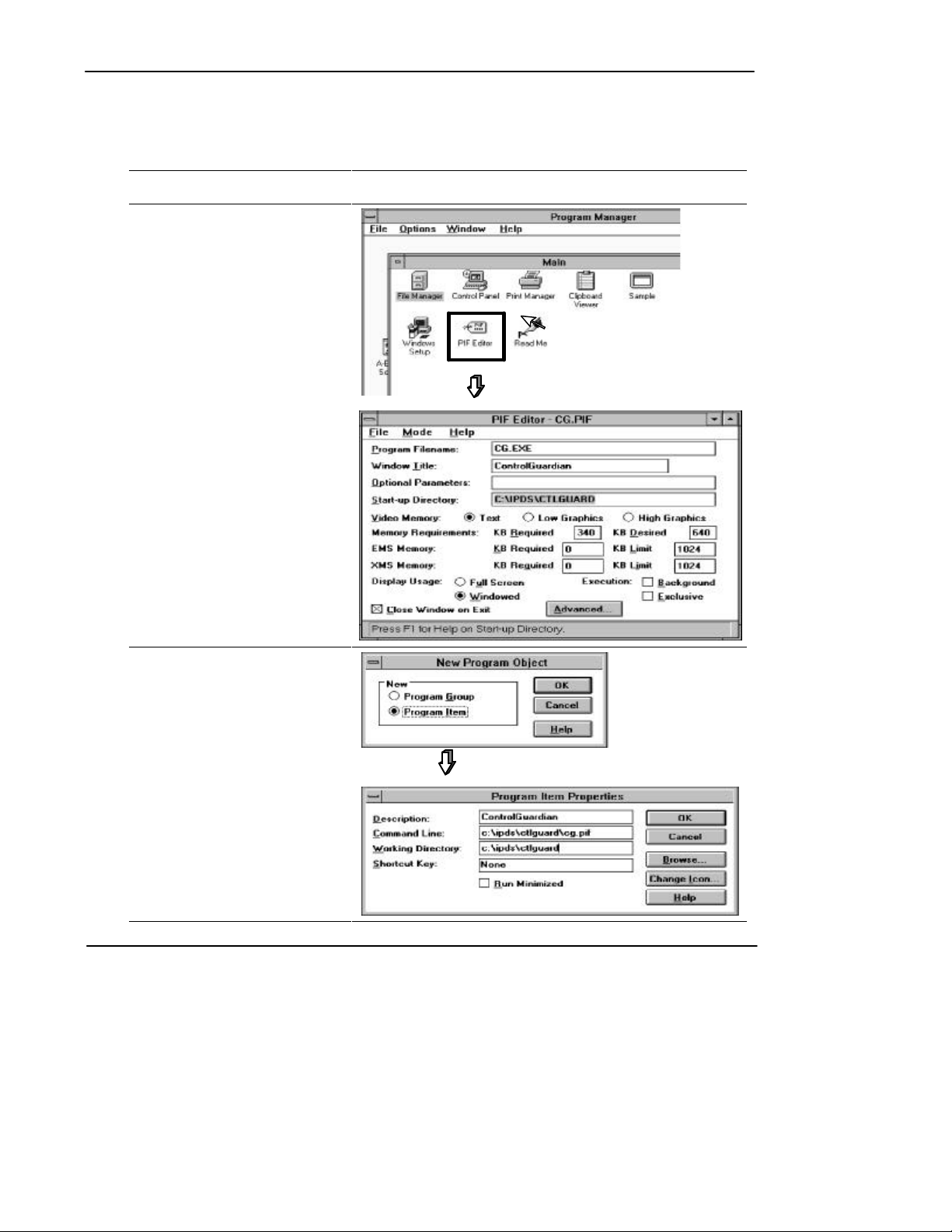
Creating a .PIF File
To create the .PIF file:
Complete this Task: In this Window:
1. SelectOpenfromthePIFEditor
File menu.
Create CG.PIF in the
x:\IPDS\CTLGUARD directory.
2. SelectNewfromtheFilemenu.
Choose Program Item.
Enter the Description.
Enter x:\IPDS\CTLGUARD\CG.PIF
for the Command Line (with x: equal
to the drive:).
Enter x:\IPDS\CTLGUARD for the
WorkingDirectory.
2-8
Page 29

Starting the Software in Windows
You must first start Windows before running ControlGuardian.
At the DOS
¬
prompt, enter:
2
-
Double-click:
To switch back and forth between running an application full screen and running it
in a window, press [Alt-Enter].
You must use 386 enhanced mode for multitasking, otherwise only the active
window can communicate. To check whether you are using 386 enhanced mode,
look under the Windows Help menu and select About Program Manager.
Installing and Starting the Software
win [Enter]
2-9
Page 30
ControlGuardian User’s Guide
Preface
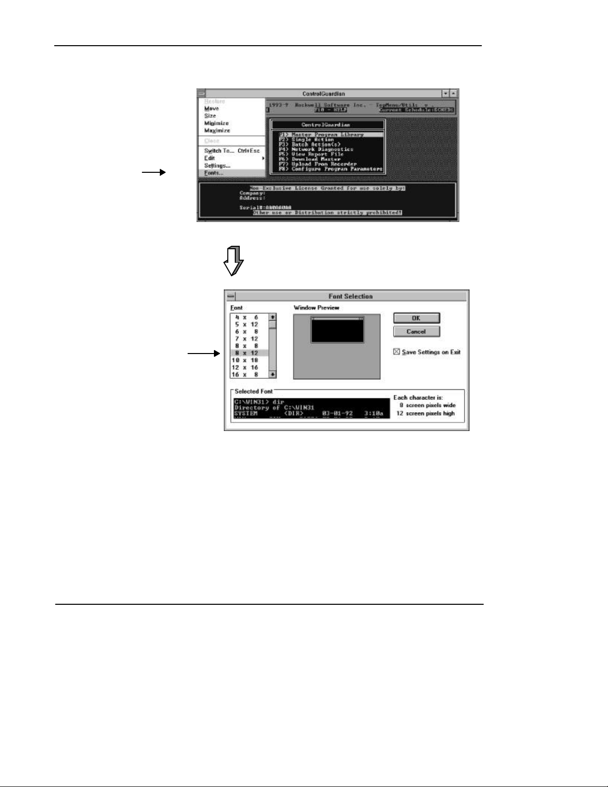
To change the size of the window, do the following:
Click the left mouse button on
¬
the system menu button and
select Fonts.
6 2 0
2-10
Select the font size you want and
-
choose the OK button.
Page 31

Exiting the Software
To exit the software, follow the instructions on the left:
From
any
screen
Esc
until the exit menu
screen is displayed
F1
Yes
Installing and Starting the Software
6 2 0
2-11
Page 32

Configuring Communications
3 Configuring Communications
Chapter Objectives
Before you can use the software to monitor and verify working programs, you have
to configure the communication device(s) for DH+, DH, and DH485 networks. Use
this chapter to:
· configure program operational parameters
· configure communication hardware
· modify a device configuration file
3-1
Page 33

Preface
device
configuration
file
list.
ControlGuardian User’s Guide
Configuring Communication Hardware
The configuration information you specify depends on the communicationhardware
you are using. For example, the required key sequences, numbered steps, and
applicable screens for configuring communication parameters for a 1784-KL
communications device are shown below:
Main Menu
Configure Program
Parameters
F8
Communication
Hardware
F1
Create
Ins
Use function keys to configure
¯
your system.
°
When you are finished, press:
Enter
to accept the configuration.
to abort the configuration and
Esc
return to the select file menu.
F3¬
Press
-
Use
to highlight the
communication device.
®
or
Press
Enter
keys
6
6 2 0
Enter
When you press
creates a communication device configuration file. This file contains the
parameters you configured for the communication device. Each device is
listed by the name and device description you entered in the communication
to accept the configuration, the software
2 0
Note Although the screens for each communication device will differ slightly than those
shown for the 1784-KL, the key sequences and numbered steps remain the same for
all of the communication devices supported by ControlGuardian. For information
on the specific configuration parameters for the communication device you are
using, locate your communication device in Table 3.A and proceed to the page
specified.
3-2
Page 34

Table 3.A
Communication Devices
If you are using this communication device: Seepage:
RS-232 Serial to DH 3-6
RS-232 Serial to KF/KE/CHO (DH+) 3-7
A-B 1784-KL (T45/T47) (DH+) 3-9
A-B 1784-KT/KT2 (DH+) 3-10
A-B 6171-IDH (DH+) 3-12
LAN Logistics Server (IPX) 3-13
Sutherland Schultz 5136-SD (DH+) 3-14
LAN Logistics Server (NetBios) 3-15
OS/2 KT Device Driver (DH+) 3-16
WinLinx/RSLinx (DH+) 3-17
A-B Ethernet Device 3-18
A-B 1784-KTX/KTXD (DH+) 3-20
A-B 1784-PCMK (DH+) 3-21
Serial Port to A-B 1747-PIC 3-23
A-B 1784-KT/KT2 with a S5-103 Cable 3-24
A-B 1784-KL with a S5-103 Cable 3-25
A-B 1784-KR 3-26
A-B 1784-PCMK with a S5-104 Cable 3-27
A-B 1784-KTX/KTXD on DH485 3-28
A-B 1770-KF3, 1747-KE, 5/03, 5/04 Ch 0 3-29
A-B 1784-KT/KT2 to DH485 3-30
A-B 1784-KL to DH485 3-31
A-B 1784-KTX/KTXD to DH485 3-32
A-B 1784-PCMK to DH485 3-33
Sutherland Schultz 5136-SD/SD2 to DH485 3-34
WinLinx/RSLinx to DH485 3-35
A-B Ethernet to DH485 3-36
LAN Logistics Server to DH485 (IPX) 3-37
LAN Logistics Server to DH485 (NetBios) 3-38
Configuring Communications
3-3
Page 35

Preface
ControlGuardian User’s Guide
Configuring Program Operational Parameters
To configure program operational parameters, follow the instructions on the left:
Main Menu
Configure Program
Parameters
F8
Program Operational
Parameters
F3
6
Use function keys
to configure parameters.
See Table 3.B.
Table 3.B
Available Function Keys for Program Operational Parameters
If you want to: Press this key:
Store temporary files to increase software operational speed.
You use this only if RAM drive is available.
Determine the number of program file backups to save. The
backups are saved under the currently displayed project name
with a three-digit file extension. The higher the extension
number,themorerecenttheback-upversionoftheprogram
file. For more information on back-up files, see chapter 7.
Determine which documentation database files to use and
which file format to use. Toggle between 6200 series and A. I.
series.
If set to 6200 Series, use 6200 documentation and the .DA1
file format. The Allen-Bradley .DA1 format consists of a .PR1
and .DA1 file.
If set to A. I. Series, use A. I. series documentation and the
.LAD file format.
2 0
F1
F2
F3
Directory to hold temporary files
Number of program backups to
save
PLC-2 Program & Database Files
(Continued)
3-4
Page 36

Configuring Communications
If you want to: Press this key:
Determine which documentation database files to use and
which file format to use. Toggle between 6200 series and A. I.
F4
PLC-3 Program & Database Files
series.
If set to 6200 series, use 6200 documentation and the .ACH
file format. You can convert .ACH format to .AF3 format for
use offlinebyusingAllen-Bradley6200PLC-3programming
software.
If set to A. I. Series, use A. I. series documentation and the
.VD1 file format.
Determine which documentation database files to use. Toggle
between 6200 series and A. I. series.
F5
PLC-5 Program and Database Files
If set to 6200 Series, use 6200 documentation and the .AF5
file format. ControlGuardian software does not support upload
and download functions with this format; the software supports
only retrieve and compare functions.
If set to A. I. Series, use A. I. series documentation and the
.X5 file format. You can convert .AF5 format to .X5 format for
use offlinebyusingAllen-Bradley6200PLC-5
programming software.
Note If you have installed release 5.2 and later of 6200 PLC-5 programming software
and ControlGuardian Software on the same programming terminal, you will not
have 6200 PLC-5 programming software support. Release 5.2 and later of 6200
PLC-5 programming software is a protected mode application and is incompatible
with ControlGuardian.
3-5
Page 37

Preface
ControlGuardian User’s Guide
Configuring the RS-232 Serial to DH
You can use the serial port (COM1, COM2, or user specified) of your programming
terminal and one of the following methods to attach to the network link or to
a processor:
· direct connect through the serial port (channel 1 on a 1775-KA module;
channel 0 on an enhanced PLC-5 processor)
· a 1770-KF2, series B communication interface module, standalone unit
· a 1785-KE communication interface module, resides in a 1771 I/O rack
· a 1771-KE communication interface module, resides in a 1771 I/O rack
· a 1771-KF communication module, standalone unit
For information on the configuration characteristics for RS-232 Serial to DH, see
Table 3.C.
Table 3.C
ConfigurationCharacteristicsfor RS-232 Serial to DH
If you want to: Press this key:
Assign a unique communication device name (1-8 characters). This field
must be defined for the software to accept the configuration. You cannot
modify this field after you accept the configuration.
Assign a description for a communication device (1-50 characters). You
must define this field for the software to accept the configuration.
Select the RS-232 Serial to DH option.
F1
F2
F3
Device Name
Enter Device Description
Select Interface Hardware
Assign a timeout for processor reply.Available choices are: 15, 20, 25, 30,
35, 40, 45, 50, 55 and 60 seconds. The default is 20 seconds.
Select your serial port setting. Toggle between COM1 and COM2. The
default is COM1.
Define a communication rate to send information. Toggle through 300, 600,
1200, 2400, 4800, 9600 and 19200 baud rates. The default is 19200 baud.
Choose the method of error checking your computer will support. Toggle
between even and none. The default is none.
Choose the serial protocol. Toggle between Half Duplex and Full Duplex.
The default is Full Duplex.
Set error detection. Toggle between:
· BCC The computer sends and accepts messages that end with a BCC
byte for error checking.
· CRC The computer sends and accepts messages with a 2-byte CRC
for error checking.
The default is BCC.
Choose your interface module type. Toggle between: KF, KG, and IDH. The
default is KF.
Enter the source station number. Parametersare:0-77and110-376.
3-6
F4
F6
F7
F8
F9
Ctrl F1
Online WaitforReply
Serial Port
Baud Rate
Parity
Serial Protocol
Error Checking Mode
Interface Module Type
F2Ctrl
Source Station Number
F3Ctrl
Page 38

Configuring Communications
Configuring the RS-232 Serial to KF/KE/CH0 (DH+)
For information on the configuration characteristics for RS-232 to KF/KE/Ch0
(DH+), see Table 3.D.
Table 3.D
ConfigurationCharacteristicsfor RS-232 Serial to KF/KE/CH0 (DH+)
If you want to: Press this key:
Assign a unique communication device name (1-8 characters). This
field must be defined for the software to accept the configuration.
You cannot modify this field. The communication device name that
you assign will appear on the screen when you use WHO.
Assign a description for a communication device (1-50 characters).
You must define this field for the software to accept the configuration.
Select the RS-232 Serial to KF/KE/CH0 (DH+) option.
F1
F2
F3
Device Name
Enter Device Description
Select Interface Hardware
Assign a timeout for processor reply.Available choices are: 15, 20,
25, 30, 35, 40, 45, 50, 55 and 60 seconds. The default is
20 seconds.
Assign a communication port. Toggle through COM1, COM2, and
user specified. If you choose the user-specified port, you must enter
the serial port I/O address and the interrupt (IRQ).
Define a communication rate to send information. Toggle through
300, 600, 1200, 2400, 4800, 9600 and 19200 baud rates. The
default is 19200 baud.
Choose the method of error checking your computer will support.
Toggle between even and none. The default is none.
Set error detection. Toggle between:
· BCC The computer sends and accepts messages that end
with a BCC byte for error checking.
· CRC The computer sends and accepts messages with a
2-byte CRC for error checking.
The default is BCC.
Choose the serial protocol. Toggle between Half Duplex and Full
Duplex. The default is Full Duplex.
Enter the source station address (1-9 characters)
F4
F5
F6
F7
F8
F9
Ctrl F1
Online WaitforReply
Communications Port
Baud Rate
Parity
Error Checking Mode
Serial Protocol
Computer Station Address
3-7
Page 39

Preface
ControlGuardian User’s Guide
You can specify a serial port other than COM1 or COM2. You have to identify the
Application tip
address and interrupt for the serial port so that it doesn’t conflict with the other
serial ports in your programming terminal. To specify another serial port, do
the following:
Main Menu
¬
-
®
¯
F5
Press
until the software prompts
you for the serial
port address.
Enter the address.
Press
Enter the interrupt number.
Enter
Configure Program
Parameters
F8 F1
Communication
Hardware
6
6 2 0
Create
Ins
Select
RS-232 Serial to
KF2/KE/CH0 (DH+)
2 0
3-8
°
Press
Enter
Page 40

Configuring 1784-KL (DH+)
Use the 1784-KL board to connect a 1784-T45 or -T47 directly to a processor or to
a local DH+ link. The 1784-KL also provides remote DH+ to DH+ programming.
For information on the configuration characteristics for 1784-KL (DH+), see
Table 3.E.
Table 3.E
ConfigurationCharacteristicsfor 1784-KL (DH+)
If you want to: Press this key:
Assign a unique communication device name (1-8 characters). This
field must be defined for the software to accept the configuration.
You cannot modify this field once you have saved the configuration.
The communication device name that you assign appears at the top
of the screen when you use WHO.
Assign a description for a communication device (1-50 characters).
You must define this field for the software to accept
the configuration.
Select the 1784-KL (DH+) option.
Configuring Communications
F1
F2
F3
Device Name
Enter Device Description
Select Interface Hardware
Assign a timeout for processor reply.Available choices are: 15, 20,
25, 30, 35, 40, 45, 50, 55 and 60 seconds. The default is
20 seconds.
Enter a name for a programming terminal (1-8 characters). This
name appears next to the station number and device on the WHO
active screen.
Define the following:
· Networkmode(choosebetween:local,remote,andDH+routing)
· Localnodeaddress(octal)
· Remoteaddress(octal)
· DestinationlinkID(decimal)forDH+routing
· Bridgeaddress(octal)forDH+routing
Enter the source station address (0-77 octal).
F4
F6
F9
Online WaitforReply
Term Name
Network Mode
Computer Station Address
F1Ctrl
3-9
Page 41

Preface
ControlGuardian User’s Guide
Configuring a 1784-KT/KT2 (DH+)
Use the 1784-KT/KT2 (DH+) option if you want to connect a programming
terminal directly to a processor, to a local DH+ link, or for programming over a
remote DH+ link. Table 3.F lists when to use which communication card.
Table 3.F
Selecting a Communication Card
If you use a: Use this communication card:
DOS-based IBMâor IBM-compatible
programming terminal
IBM microchannel programming terminal 1784-KT2
1784-KT
3-10
Page 42

For information on the configuration characteristics for 1784-KT/KT2 (DH+), see
Table 3.G.
Table 3.G
ConfigurationCharacteristicsfor the 1784-KT/KT2 (DH+)
If you want to: Press this key:
Assign a unique communication device name (1-8 characters). This
field must be defined for the software to accept the configuration.
You cannot modify this field. The communication device name that
you assign appears at the top of the screen when you use WHO.
Assign a description for a communication device (1-50 characters).
You must define this field for the software to accept
the configuration.
Select the 1784-KT/KT2 (DH+) option.
F1
F2
F3
Configuring Communications
Device Name
Enter Device Description
Select Interface Hardware
Assign a timeout for processor reply. Available choices are: 15, 20,
25, 30, 35, 40, 45, 50, 55 and 60 seconds. The default is
20 seconds.
Choose the 1784-KT/KT2 communications board address. You can
choose from the following:
· C000H(000011) · D000H (001011)
· C400H(100011) · D400H (101011)
· C800H(010011) · D800H (011011)
· CC00H(110011) · DC00H (111011)
Enter a name for a programming terminal (1-8 characters). This
name appears next to the station number and device on the WHO
active screen.
Define the following:
· Networkmode(choosebetween:local,remote,andDH+routing)
· Localnodeaddress(octal)
· Remoteaddress(octal)
· DestinationlinkID(decimal)forDH+routing
· Bridgeaddress(octal)forDH+routing
Enter the source station address (0-77 octal).
The actual device drivers for the 1784-KT or 1784-KT2 communications cards are
separate so you can specify both in one batch file.
F4
F5
F6
F9
Online WaitforReply
KT Communications
BoardAddr
Term Name
Network Mode
Computer Station Address
F1Ctrl
3-11
Page 43

Preface
ControlGuardian User’s Guide
Configuring a 6171-IDH (DH+)
For information on the configuration characteristics for 6171-IDH, see Table 3.H.
Table 3.H
ConfigurationCharacteristicsfor 6171-IDH (DH+)
If you want to: Press this key:
Assign a unique communication device name (1-8 characters). This
field must be defined for the software to accept the configuration.
You cannot modify this field. The communication device name that
you assign appears at the top of the screen when you use WHO.
Assign a description for a communication device (1-50 characters).
You must define this field for the software to accept
the configuration.
Select the 6171-IDH (DH+) option.
F1
F2
F3
Device Name
Enter Device Description
Select Interface Hardware
Assign a timeout for processor reply.Available choices are: 15, 20,
25, 30, 35, 40, 45, 50, 55 and 60 seconds. The default is
20 seconds.
Assign a communication port. Toggle through COM1, COM2, and
user specified. If you choose the user-specified port, you must
enter the serial port I/O address and the interrupt (IRQ). For more
information about specifying a COM port, see page 3-8.
Enter the source station address (0-77 octal).
F4
F5
Online WaitforReply
Communications Port
Computer Station Address
F1Ctrl
3-12
Page 44

Configuring a LAN Logistics Server (IPX)
For information on the configuration characteristics for a LAN Logistics Server
(IPX), see Table 3.I.
Table 3.I
ConfigurationCharacteristicsfor the LAN Logistics Server (IPX)
If you want to: Press this key:
Assign a unique communication device name (1-8 characters). This
field must be defined for the software to accept the configuration.
You cannot modify this field after you save the configuration. The
communication device name that you assign appears at the top of
the screen when you use WHO.
Assign a description for a communication device (1-50 characters).
You must define this field for the software to accept
the configuration.
Select the LAN Logistics Server (IPX) option.
F1
F2
F3
Configuring Communications
Device Name
Enter Device Description
Select Interface Hardware
Assign a timeout for processor reply. Available choices are: 15, 20,
25, 30, 35, 40, 45, 50, 55 and 60 seconds. The default is
20 seconds.
Enter default Novell Netware Server name (1-9 characters).
Enter a programming terminal name (1-8 characters).
Define the following:
· Networkmode(choosebetween:local,remoteand,DH+routing)
· Localnodeaddress(octal)
· Remoteaddress(octal)
· DestinationlinkID(decimal)forDH+routing
· Bridgeaddress(octal)forDH+routing
F4
F5
F6
F9
Online WaitforReply
Default Server Name
Terminal Name
Network Mode
3-13
Page 45

Preface
ControlGuardian User’s Guide
Configuring a Sutherland Schultz 5136-SD Board (DH+)
For information on the configuration characteristics for a Sutherland Schultz
5136-SD Board (DH+), see Table 3.J.
Table 3.J
ConfigurationCharacteristicsfor the Sutherland Schultz 5136-SD (DH+)
If you want to: Press this key:
Assign a unique communication device name (1-8 characters). This
field must be defined for the software to accept the configuration.
You cannot modify this field. The communication device name that
you assign appears at the top of the screen when you use WHO.
Assign a description for a communication device (1-50 characters).
You must define this field for the software to accept
the configuration.
Select the S&S 5136-SD (DH+) option.
F1
F2
F3
Device Name
Enter Device Description
Select Interface Hardware
Assign a timeout for processor reply. Available choices are: 15, 20,
25, 30, 35, 40, 45, 50, 55 and 60 seconds. The default is
20 seconds.
Enter SD bit address. The default is D800.
Enter SD interrupt number. Thedefaultis5.
Enter SD Port Address number. Thedefaultis0250.
Enter the source station address (0-77 octal).
F4
F5
F6
F7
Online WaitforReply
SD Communications Board Address
SD Communications Board IRQ
SD Communications Board Port
Computer Station Address
F1Ctrl
3-14
Page 46

Configuring Communications
Configuring a LAN Logistics Server (NetBios)
For information on the configuration characteristics for a LAN Logistics Server
(NetBios), see Table 3.K.
Table 3.K
ConfigurationCharacteristicsfor the LAN Logistics Server (NetBios)
If you want to: Press this key:
Assign a unique communication device name (1-8 characters). This
field must be defined for the software to accept the configuration.
You cannot modify this field after you save the configuration. The
communication device name that you assign appears at the top of
the screen when you use WHO.
Assign a description for a communication device (1-50 characters).
You must define this field for the software to accept
the configuration.
Select the LAN Logistics Server (NetBios) option.
F1
F2
F3
Device Name
Enter Device Description
Select Interface Hardware
Assign a timeout for processor reply. Available choices are: 15, 20,
25, 30, 35, 40, 45, 50, 55 and 60 seconds. The default is
20 seconds.
Enter default Novell Netware Server name (1-9characters).
Enter a programming terminal name (1-8characters).
Define the following:
· Networkmode(choosebetween:local,remote,andDH+routing)
· Localnodeaddress(octal)
· Remoteaddress(octal)
· DestinationlinkID(decimal)forDH+routing
· Bridgeaddress(octal)forDH+routing
The default is local.
F4
F5
F6
F9
Online WaitforReply
Default Server Name
Terminal Name
Network Mode
3-15
Page 47

Preface
ControlGuardian User’s Guide
Configuring an OS/2âKT Device Driver (DH+)
For information on the configuration characteristics for an OS/2 KT Device Driver
(DH+), see Table 3.L.
Table 3.L
ConfigurationCharacteristicsfor the OS/2 KT Driver Device (DH+)
If you want to: Press this key:
Assign a unique communication device name (1-8 characters). This
field must be defined for the software to accept the configuration.
You cannot modify this field after you save the configuration. The
communication device name that you assign appears at the top of
the screen when you use WHO.
Assign a description for a communication device (1-50 characters).
You must define this field for the software to accept
the configuration.
Select the OS/2 KT Driver Device (DH+) option.
F1
F2
F3
Device Name
Enter Device Description
Select Interface Hardware
Assign a timeout for processor reply. Available choices are: 15, 20,
25, 30, 35, 40, 45, 50, 55 and 60 seconds. The default is
20 seconds.
Enter KT device driver name. The default is KTDRV1.
Define the following:
· Networkmode(choosebetween:local,remote,andDH+routing)
· Localnodeaddress(octal)
· Remoteaddress(octal)
· DestinationlinkID(decimal)forDH+routing
· Bridgeaddress(octal)forDH+routing
F4
F5
F9
Online WaitforReply
OS2 KT Device Driver Name
Network Mode
3-16
Page 48

Configuring a WinLinx/RSLinx Driver (DH+)
For information on the configuration characteristics for a WinLinx/RSLinx Driver
(DH+), see Table 3.M.
Table 3.M
ConfigurationCharacteristicsfor the WinLinx/RSLinx Driver (DH+)
If you want to: Press this key:
Assign a unique communication device name (1-8 characters). This
field must be defined for the software to accept the configuration.
You cannot modify this field after you save the configuration. The
communication device name that you assign appears at the top of
the screen when you use WHO.
Assign a description for a communication device (1-50 characters).
You must define this field for the software to accept
the configuration.
Select the WinLinx/RSLinx (DH+) option.
F1
F2
F3
Configuring Communications
Device Name
Enter Device Description
Select Interface Hardware
Assign a timeout for processor reply. Available choices are: 15, 20,
25, 30, 35, 40, 45, 50, 55 and 60 seconds. The default is
20 seconds.
Enter KT device driver name (1-8 characters). The default
is KTDRV1.
Enter a programming terminal name (1-8 characters).
Define the following:
· Networkmode(choosebetween:local,remote,andDH+routing)
· Localnodeaddress(octal)
· Remoteaddress(octal)
· DestinationlinkID(decimal)forDH+routing
· Bridgeaddress(octal)forDH+routing
The default network mode is local.
F4
F5
F6
F9
Online WaitforReply
Default Server Name
Terminal Name
Network Mode
3-17
Page 49

Preface
ControlGuardian User’s Guide
Configuring an Ethernet Device
For information on the configuration characteristics for an Ethernet Device, see
Table 3.N.
Table 3.N
ConfigurationCharacteristicsfor an A-B Ethernet Device
If you want to: Press this key:
Assign a unique communication device name (1-8 characters). This
field must be defined for the software to accept the configuration.
You cannot modify this field after you save the configuration. The
communication device name that you assign appears at the top of
the screen when you use WHO.
Assign a description for a communication device (1-50 characters).
You must define this field for the software to accept
the configuration.
Select the A-B Ethernet Device option.
F1
F2
F3
Device Name
Enter Device Description
Select Interface Hardware
Assign a timeout for processor reply.Available choices are: 15, 20,
25, 30, 35, 40, 45, 50, 55 and 60 seconds. The default is
20 seconds.
Enter a destination subnet address. The default is 000.000.000.000
To connect to a remote destination subnet, enter the first three
octets of the destination subnet (xxx.xxx.xxx.000).
Note: Only devices between 0 and 255 on the subnet you specify
can be addressed.
Select local Ethernet or Ethernet to DH+. If you select Ethernet to
DH+, you must also specify:
bridge address
(last three digits of the IP address for the EI module)
module type (PLC-5/250 RM or PLC-5/250 KA)
channel (2 or 3)
pushwheel (1-8,PLC-5/250KAonly)
F4
F5
F9
Online WaitforReply
Destination Subnet Mask
Local
F2
F3
F4
F5
Bridge Address
Module Type
Channel
Pushwheel
3-18
Page 50

Configuring Communications
To communicate on an Ethernet network, you must also have FTP Software
ä
PC/TCP Network Softwareä. To use the PC/TCP software and ControlGuardian on
the same terminal, you must use expanded memory or have the ability to load
enoughapplicationsintohighmemorysothatControlGuardianhasenough memory.
To obtain the PC/TCP Network Software, contact:
FTP Software, Inc.
2 High Street
North Andover, MA 01845
(508) 685-3300
3-19
Page 51

Preface
ControlGuardian User’s Guide
Configuring a 1784-KTX/KTXD (DH+)
For information on the configuration characteristics for 1784-KTX/KTXD (DH+),
see Table 3.O.
Table 3.O
ConfigurationCharacteristicsfor the 1784-KTX/KTXD (DH+)
If you want to: Press this key:
Assign a unique communication device name (1-8 characters). This
field must be defined for the software to accept the configuration.
You cannot modify this field. The communication device name that
you assign appears at the top of the screen when you use WHO.
Assign a description for a communication device (1-50 characters).
You must define this field for the software to accept
the configuration.
Select the 1784-KTX/KTXD (DH+) option.
F1
F2
F3
Device Name
Enter Device Description
Select Interface Hardware
Assign a timeout for processor reply. Available choices are: 15, 20,
25, 30, 35, 40, 45, 50, 55 and 60 seconds. The default is
20 seconds.
The 1784-KTX communication card can use any 4KB block of
memory on any 4K boundary between A000 and EF00
(hexadecimal).
Enter a name for a programming terminal (1-8 characters). This
name appears next to the station number and device on the WHO
active screen.
Define the following:
· Networkmode(choosebetween:local,remote,andDH+routing)
· Localnodeaddress(octal)
· Remoteaddress(octal)
· DestinationlinkID(decimal)forDH+routing
· Bridgeaddress(octal)forDH+routing
Enter the source station address (0-77 octal).
F4
F5
F6
F9
Online WaitforReply
KTX Communications
BoardAddr
Term Name
Network Mode
Computer Station Address
F1Ctrl
3-20
Page 52

Configuring a 1784-PCMK (DH+)
Use the 1784-PCMK (DH+) option if you want to connect a programming terminal
directly to a processor,to a local DH+ link, or for programming over a remote DH+
link. Use the 1784-PCMK option (DH+) if you are using a PCMIA programming
terminal (notebook computer).
For information on the configuration characteristics for 1784-PCMK (DH+), see
Table 3.P.
Table 3.P
ConfigurationCharacteristicsfor the 1784-PCMK (DH+)
If you want to: Press this key:
Assign a unique communication device name (1-8 characters). This
field must be defined for the software to accept the configuration.
You cannot modify this field. The communication device name that
you assign appears at the top of the screen when you use WHO.
Assign a description for a communication device (1-50 characters).
You must define this field for the software to accept
the configuration.
Select the 1784-PCMK (DH+) option.
Configuring Communications
F1
F2
F3
Device Name
Enter Device Description
Select Interface Hardware
Assign a timeout for processor reply. Available choices are: 15, 20,
25, 30, 35, 40, 45, 50, 55 and 60 seconds. The default is
20 seconds.
Choose the 1784-PCMK communications board address. You can
choose from the following:
· A300H(A3) · CB00H (CB)
· A700H(A7) · CF00H (CF)
· AB00H(AB) · D300H (D3)
· AF00H(AF) · D700H (D7)
· B300H(B3) · DB00H (DB)
· B700H(B7) · DF00H (DF)
· BB00H(BB) · E300H (E3)
· BF00H(BF) · E700H (E7)
· C300H(C3) · EB00H (EB)
· C700H(C7)
Enter a name for a programming terminal (1-8 characters). This
name appears next to the station number and device on the WHO
active screen.
F4
F5
F6
Online WaitforReply
PCMK Communications
Board Addr
Term Name
(Continued)
3-21
Page 53

Preface
ControlGuardian User’s Guide
If you want to: Press this key:
Define the following:
· Networkmode(choosebetween:local,remote,andDH+routing)
· Localnodeaddress(octal)
· Remoteaddress(octal)
· DestinationlinkID(decimal)forDH+routing
· Bridgeaddress(octal)forDH+routing
Enter the source station address (0-77 octal).
F9
Network Mode
Computer Station Address
F1Ctrl
3-22
Page 54

Configuring a Serial Port to A-B 1747-PIC
For information on the configuration characteristics for Serial Port to A-B
1747-PIC, see Table 3.Q.
Table 3.Q
ConfigurationCharacteristicsfor Serial Port to A-B 1747-PIC
If you want to: Press this key:
Assign a unique communication device name (1-8 characters). This
field must be defined for the software to accept the configuration.
You cannot modify this field. The communication device name that
you assign appears at the top of the screen when you use WHO.
Assign a description for a communication device (1-50 characters).
You must define this field for the software to accept
the configuration.
Select the Serial Port to A-B 1747-PIC option.
F1
F2
F3
Configuring Communications
Device Name
Enter Device Description
Select Interface Hardware
Assign a timeout for processor reply. Available choices are: 15, 20,
25, 30, 35, 40, 45, 50, 55 and 60 seconds. The default is
20 seconds.
Assign a communication port. Toggle through COM1, COM2, and
user specified. If you choose the user-specified port, you must
enter the serial port I/O address and the interrupt (IRQ). For more
information about specifying a COM port, see page 3-8.
Define a communication rate to send information. Toggle through
300, 600, 1200, 2400, 4800, 9600 and 19200 baud rates. The
default is 19200 baud.
F4
F5
F6
Online WaitforReply
Communications Port
Baud Rate
3-23
Page 55

Preface
ControlGuardian User’s Guide
Configuring an A-B 1784-KT/KT2 with a S5-103 Cable
For information on the configuration characteristics for A-B 1784-KT/KT2 with a
S5-103 Cable, see Table 3.R.
Table 3.R
ConfigurationCharacteristicsfor A-B 1784-KT/KT2 With S5-103 Cable
If you want to: Press this key:
Assign a unique communication device name (1-8 characters). This
field must be defined for the software to accept the configuration.
You cannot modify this field. The communication device name that
you assign appears at the top of the screen when you use WHO.
Assign a description for a communication device (1-50 characters).
You must define this field for the software to accept
the configuration.
Select the A-B 1784-KT/KT2 with S5-103 Cable option.
F1
F2
F3
Device Name
Enter Device Description
Select Interface Hardware
Assign a timeout for processor reply. Available choices are: 15, 20,
25, 30, 35, 40, 45, 50, 55 and 60 seconds. The default is
20 seconds.
Choose the 1784-KT/KT2 communications board address. You can
choose from the following:
· C000H(000011) · D000H (001011)
· C400H(100011) · D400H (101011)
· C800H(010011) · D800H (011011)
· CC00H(110011) · DC00H (111011)
Define a communication rate to send information. Toggle through
300, 600, 1200, 2400, 4800, 9600 and 19200 baud rates. The
default is 19200 baud.
Enter the source station address (0-377 octal).
F4
F5
F6
Online WaitforReply
KT Communications
BoardAddr
Baud Rate
Computer Station Address
F1Ctrl
3-24
Page 56

Configuring Communications
Configuring an A-B 1784-KL with a S5-103 Cable
For information on the configuration characteristics for A-B 1784-KL with aS5-103
Cable, see Table 3.S.
Table 3.S
ConfigurationCharacteristicsfor A-B 1784-KL With S5-103 Cable
If you want to: Press this key:
Assign a unique communication device name (1-8 characters). This
field must be defined for the software to accept the configuration.
You cannot modify this field. The communication device name that
you assign appears at the top of the screen when you use WHO.
Assign a description for a communication device (1-50 characters).
You must define this field for the software to accept
the configuration.
Select the A-B 1784-KL with S5-103 Cable option.
F1
F2
F3
Device Name
Enter Device Description
Select Interface Hardware
Assign a timeout for processor reply. Available choices are: 15, 20,
25, 30, 35, 40, 45, 50, 55 and 60 seconds. The default is
20 seconds.
Define a communication rate to send information. Toggle through
300, 600, 1200, 2400, 4800, 9600 and 19200 baud rates. The
default is 19200 baud.
Enter the source station address (0-377 octal).
F4
F6
Online WaitforReply
Baud Rate
Computer Station Address
F1Ctrl
3-25
Page 57

Preface
ControlGuardian User’s Guide
Configuring an A-B 1784-KR
For information on the configuration characteristics for A-B 1784-KR, see
Table 3.T.
Table 3.T
ConfigurationCharacteristicsfor A-B 1784-KR
If you want to: Press this key:
Assign a unique communication device name (1-8 characters). This
field must be defined for the software to accept the configuration.
You cannot modify this field. The communication device name that
you assign appears at the top of the screen when you use WHO.
Assign a description for a communication device (1-50 characters).
You must define this field for the software to accept
the configuration.
Select the A-B 1784-KR option.
F1
F2
F3
Device Name
Enter Device Description
Select Interface Hardware
Assign a timeout for processor reply. Available choices are: 15, 20,
25, 30, 35, 40, 45, 50, 55 and 60 seconds. The default is
20 seconds.
Choose the 1784-KL communications board address. You can
choose from the following:
· C000H · E000H (000111)
· C800H · E800H (010111)
· D000H
· D800H
Define a communication rate to send information. Toggle through
300, 600, 1200, 2400, 4800, 9600 and 19200 baud rates. The
default is 19200 baud.
Choose the KR I/O board address. you can choose from 2A8, 2B8,
2E8, 300, 320, and 360. The default is 300.
Choose the KR interrupt number.You can choose from 2, 3, 4,
and 5. The default is 5.
Enter the source station address (decimal).
F4
F5
F6
F7
F8
Online WaitforReply
KR Memory Address
Baud Rate
KR I/O Board Address
KR Interrupt Number
Computer Station Address
F1Ctrl
3-26
Page 58

Configuring Communications
Configuring an A-B 1784-PCMK with a S5-104 Cable
For information on the configuration characteristics for A-B 1784-PCMK with a
S5-104 Cable, see Table 3.U.
Table 3.U
ConfigurationCharacteristicsfor A-B 1784-PCMK With S5-104 Cable
If you want to: Press this key:
Assign a unique communication device name (1-8 characters). This
field must be defined for the software to accept the configuration.
You cannot modify this field. The communication device name that
you assign appears at the top of the screen when you use WHO.
Assign a description for a communication device (1-50 characters).
You must define this field for the software to accept
the configuration.
Select the A-B 1784-PCMK with S5-104 Cable option.
F1
F2
F3
Device Name
Enter Device Description
Select Interface Hardware
Assign a timeout for processor reply. Available choices are: 15, 20,
25, 30, 35, 40, 45, 50, 55 and 60 seconds. The default is
20 seconds.
Choose the 1784-PCMK communications board address. You can
choose from the following:
· A300H(A3) · CB00H (CB)
· A700H(A7) · CF00H (CF)
· AB00H(AB) · D300H (D3)
· AF00H(AF) · D700H (D7)
· B300H(B3) · DB00H (DB)
· B700H(B7) · DF00H (DF)
· BB00H(BB) · E300H (E3)
· BF00H(BF) · E700H (E7)
· C300H(C3) · EB00H (EB)
· C700H(C7)
Define a communication rate to send information. Toggle through
300, 600, 1200, 2400, 4800, 9600 and 19200 baud rates. The
default is 19200 baud.
Enter the source station address (decimal).
F4
F5
F6
Online WaitforReply
PCMK Communications
Board Addr
Baud Rate
Computer Station Address
F1Ctrl
3-27
Page 59

Preface
ControlGuardian User’s Guide
Configuring a 1784-KTX/KTXD on DH485
For information on the configuration characteristics for 1784-KTX/KTXD on
DH485, see Table 3.V.
Table 3.V
ConfigurationCharacteristicsfor the 1784-KTX/KTXD on DH485
If you want to: Press this key:
Assign a unique communication device name (1-8 characters). This
field must be defined for the software to accept the configuration.
You cannot modify this field. The communication device name that
you assign appears at the top of the screen when you use WHO.
Assign a description for a communication device (1-50 characters).
You must define this field for the software to accept
the configuration.
Select the 1784-KTX/KTXD on DH485 option.
F1
F2
F3
Device Name
Enter Device Description
Select Interface Hardware
Assign a timeout for processor reply. Available choices are: 15, 20,
25, 30, 35, 40, 45, 50, 55 and 60 seconds. The default is
20 seconds.
The 1784-KTX communication card can use any 4KB block of
memory on any 4K boundary between A000 and EF00
(hexadecimal).
Enter a name for a programming terminal (1-8 characters). This
name appears next to the station number and device on the WHO
active screen.
Enter the source station address (decimal).
F4
F5
F6
Online WaitforReply
KTX Communications
BoardAddr
Term Name
Computer Station Address
F1Ctrl
3-28
Page 60

Configuring Communications
Configuring an A-B 1770-KF3, 1747-KE, 5/03, 5/04 Ch 0
For information on the configuration characteristics for 1770-KF3, 1747-KE, 5/03,
5/04 Ch 0, see Table 3.W.
Table 3.W
ConfigurationCharacteristicsfor A-B 1770-KF3, 1747-KE, 5/03, 5/04 Ch 0
If you want to: Press this key:
Assign a unique communication device name (1-8 characters). This
field must be defined for the software to accept the configuration.
You cannot modify this field. The communication device name that
you assign appears at the top of the screen when you use WHO.
Assign a description for a communication device (1-50 characters).
You must define this field for the software to accept
the configuration.
Select the A-B 1770-KF3, 1747-KE, 5/03, 5/04 Ch 0 option.
F1
F2
F3
Device Name
Enter Device Description
Select Interface Hardware
Assign a timeout for processor reply. Available choices are: 15, 20,
25, 30, 35, 40, 45, 50, 55 and 60 seconds. The default is
20 seconds.
Assign a communication port. Toggle through COM1, COM2, and
user specified. If you choose the user-specified port, you must
enter the serial port I/O address and the interrupt (IRQ). For more
information about specifying a COM port, see page 3-8.
Define a communication rate to send information. Toggle through
300, 600, 1200, 2400, 4800, 9600 and 19200 baud rates. The
default is 19200 baud.
Choose the method of error checking your computer will support.
Toggle between even and none. The default is none.
Set error detection. Toggle between:
· BCC The computer sends and accepts messages that end
with a BCC byte for error checking.
· CRC The computer sends and accepts messages with a
2-byte CRC for error checking.
The default is BCC.
Choose the serial protocol. Toggle between Half Duplex and Full
Duplex. The default is Full Duplex.
Enter the source station address (decimal).
F4
F5
F6
F7
F8
F9
Online WaitforReply
Communications Port
Baud Rate
Parity
Error Checking Mode
Serial Protocol
Computer Station Address
F1Ctrl
3-29
Page 61

Preface
ControlGuardian User’s Guide
Configuring an A-B 1784-KT/KT2 to DH485
For information on the configuration characteristics for 1784-KT/KT2 to DH485,
see Table 3.X.
Table 3.X
ConfigurationCharacteristicsfor A-B 1784-KT/KT2 to DH485
If you want to: Press this key:
Assign a unique communication device name (1-8 characters). This
field must be defined for the software to accept the configuration.
You cannot modify this field. The communication device name that
you assign appears at the top of the screen when you use WHO.
Assign a description for a communication device (1-50 characters).
You must define this field for the software to accept
the configuration.
Select the A-B 1784-KT/KT2 to DH485 option.
F1
F2
F3
Device Name
Enter Device Description
Select Interface Hardware
Assign a timeout for processor reply. Available choices are: 15, 20,
25, 30, 35, 40, 45, 50, 55 and 60 seconds. The default is
20 seconds.
Choose the 1784-KT/KT2 communications board address. You can
choose from the following:
· C000H(000011) · D000H (001011)
· C400H(100011) · D400H (101011)
· C800H(010011) · D800H (011011)
· CC00H(110011) · DC00H (111011)
Enter a programming terminal name (1-8characters).
Enter the 1785-KA5 DH+ address (0-77 octal).
Enter a destination link DH+ address (decimal).
Enter the source station address (0-377 octal).
F4
F5
F6
F8
F9
Online WaitforReply
KT Communications
BoardAddr
Terminal Name
1785-KA5 Address
Destination Link
Computer Station Address
F1Ctrl
3-30
Page 62

Configuring a A-B 1784-KL to DH485
For information on the configuration characteristics for 1784-KL to DH485, see
Table 3.Y.
Table 3.Y
ConfigurationCharacteristicsfor A-B 1784-KL to DH485
If you want to: Press this key:
Assign a unique communication device name (1-8 characters). This
field must be defined for the software to accept the configuration.
You cannot modify this field. The communication device name that
you assign appears at the top of the screen when you use WHO.
Assign a description for a communication device (1-50 characters).
You must define this field for the software to accept
the configuration.
Select the A-B 1784-KL to DH485 option.
Configuring Communications
F1
F2
F3
Device Name
Enter Device Description
Select Interface Hardware
Assign a timeout for processor reply. Available choices are: 15, 20,
25, 30, 35, 40, 45, 50, 55 and 60 seconds. The default is
20 seconds.
Enter a programming terminal name (1-8characters).
Enter the 1785-KA5 DH+ address (0-77 octal).
Enter a destination link DH+ address (decimal).
Enter the source station address (0-377 octal).
F4
F6
F8
F9
Online WaitforReply
Terminal Name
1785-KA5 Address
Destination Link
Computer Station Address
F1Ctrl
3-31
Page 63

Preface
ControlGuardian User’s Guide
Configuring an A-B 1784-KTX/KTXD to DH485
For information on the configuration characteristics for 1784-KTX/KTXD to
DH485, see Table 3.Z.
Table 3.Z
ConfigurationCharacteristicsfor A-B 1784-KTX/KTXD to DH485
If you want to: Press this key:
Assign a unique communication device name (1-8 characters). This
field must be defined for the software to accept the configuration.
You cannot modify this field. The communication device name that
you assign appears at the top of the screen when you use WHO.
Assign a description for a communication device (1-50 characters).
You must define this field for the software to accept
the configuration.
Select the A-B 1784-KTX/KTXD to DH485 option.
F1
F2
F3
Device Name
Enter Device Description
Select Interface Hardware
Assign a timeout for processor reply. Available choices are: 15, 20,
25, 30, 35, 40, 45, 50, 55 and 60 seconds. The default is
20 seconds.
The 1784-KTX communication card can use any 4KB block of
memory on any 4K boundary between A000 and EF00
(hexadecimal).
Enter a programming terminal name (1-8characters).
Enter the 1785-KA5 DH+ address (0-77 octal).
Enter a destination link DH+ address (decimal).
Enter the source station address (0-377 octal).
F4
F5
F6
F8
F9
Online WaitforReply
KTX Communications
BoardAddr
Terminal Name
1785-KA5 Address
Destination Link
Computer Station Address
F1Ctrl
3-32
Page 64

Configuring an A-B 1784-PCMK to DH485
For information on the configuration characteristics for 1784-PCMK to DH485, see
Table 3.AA.
Table 3.AA
ConfigurationCharacteristicsfor A-B 1784-PCMK to DH485
If you want to: Press this key:
Assign a unique communication device name (1-8 characters). This
field must be defined for the software to accept the configuration.
You cannot modify this field. The communication device name that
you assign appears at the top of the screen when you use WHO.
Assign a description for a communication device (1-50 characters).
You must define this field for the software to accept
the configuration.
Select the A-B 1784-KTX/KTXD to DH485 option.
F1
F2
F3
Configuring Communications
Device Name
Enter Device Description
Select Interface Hardware
Assign a timeout for processor reply. Available choices are: 15, 20,
25, 30, 35, 40, 45, 50, 55 and 60 seconds. The default is
20 seconds.
Choose the 1784-PCMK communications board address. You can
choose from the following:
· A300H(A3) · CB00H (CB)
· A700H(A7) · CF00H (CF)
· AB00H(AB) · D300H (D3)
· AF00H(AF) · D700H (D7)
· B300H(B3) · DB00H (DB)
· B700H(B7) · DF00H (DF)
· BB00H(BB) · E300H (E3)
· BF00H(BF) · E700H (E7)
· C300H(C3) · EB00H (EB)
· C700H(C7)
Enter a programming terminal name (1-8characters).
Enter the 1785-KA5 DH+ address (0-77 octal).
Enter a destination link DH+ address (decimal).
Enter the source station address (0-377 octal).
F4
F5
F6
F8
F9
Online WaitforReply
PCMK Communications
Board Addr
Terminal Name
1785-KA5 Address
Destination Link
Computer Station Address
F1Ctrl
3-33
Page 65

Preface
ControlGuardian User’s Guide
Configuring a Sutherland Schultz 5136-SD/SD2 to DH485
For information on the configuration characteristics for a Sutherland Schultz
5136-SD/SD2 to DH485, see Table 3.AB.
Table 3.AB
ConfigurationCharacteristicsfor Sutherland Schultz 5136-SD/SD2 to
DH485
If you want to: Press this key:
Assign a unique communication device name (1-8 characters). This
field must be defined for the software to accept the configuration.
You cannot modify this field. The communication device name that
you assign appears at the top of the screen when you use WHO.
Assign a description for a communication device (1-50 characters).
You must define this field for the software to accept
the configuration.
Select the Sutherland Schultz 5136-SD/SD2 to DH485 option.
F1
F2
F3
Device Name
Enter Device Description
Select Interface Hardware
Assign a timeout for processor reply. Available choices are: 15, 20,
25, 30, 35, 40, 45, 50, 55 and 60 seconds. The default is
20 seconds.
Enter SD bit address. The default is D800.
Enter SD interrupt number. Thedefaultis5.
Enter SD Port Address number. Thedefaultis0250.
Enter the 1785-KA5 DH+ address (0-77 octal).
Enter a destination link DH+ address (decimal).
Enter the source station address (0-377 octal).
F4
F5
F6
F7
F8
F9
Online WaitforReply
SD Communications Board
Address
SD Communications Board
IRQ
SD Communications Board
Port
1785-KA5 Address
Destination Link
Computer Station Address
F1Ctrl
3-34
Page 66

Configuring Communications
Configuring a WinLinx/RSLinx Driver to DH485
For information on the configuration characteristics for a WinLinx/RSLinx Driver
to DH485, see Table 3.AC.
Table 3.AC
ConfigurationCharacteristicsfor the WinLinx/RSLinx Driver to DH485
If you want to: Press this key:
Assign a unique communication device name (1-8 characters). This
field must be defined for the software to accept the configuration.
You cannot modify this field after you save the configuration. The
communication device name that you assign appears at the top of
the screen when you use WHO.
Assign a description for a communication device (1-50 characters).
You must define this field for the software to accept
the configuration.
Select the WinLinx/RSLinx to DH485 option.
F1
F2
F3
Device Name
Enter Device Description
Select Interface Hardware
Assign a timeout for processor reply. Available choices are: 15, 20,
25, 30, 35, 40, 45, 50, 55 and 60 seconds. The default is
20 seconds.
Enter KT device driver name (1-8 characters). The default
is KTDRV1.
Enter a programming terminal name (1-8 characters).
Enter the 1785-KA5 DH+ address (0-77 octal).
Enter a destination link DH+ address (decimal).
F4
F5
F6
F8
F9
Online WaitforReply
Default Server Name
Terminal Name
1785-KA5 Address
Destination Link
3-35
Page 67

Preface
ControlGuardian User’s Guide
Configuring an A-B Ethernet to DH485
For information on the configuration characteristics for an Ethernet Device to
DH485, see Table 3.AD.
Table 3.AD
ConfigurationCharacteristicsfor Configuring an A-B Ethernet to DH485
If you want to: Press this key:
Assign a unique communication device name (1-8 characters). This
field must be defined for the software to accept the configuration.
You cannot modify this field. The communication device name that
you assign appears at the top of the screen when you use WHO.
Assign a description for a communication device (1-50 characters).
You must define this field for the software to accept
the configuration.
Select the A-B Ethernet to DH485 option.
F1
F2
F3
Device Name
Enter Device Description
Select Interface Hardware
Assign a timeout for processor reply. Available choices are: 15, 20,
25, 30, 35, 40, 45, 50, 55 and 60 seconds. The default is
20 seconds.
Enter a destination subnet address. The default is 000.000.000.000
To connect to a remote destination subnet, enter the first three
octets of the destination subnet (xxx.xxx.xxx.000).
Note: Only devices between 0 and 255 on the subnet you specify
can be addressed.
Enter the 1785-KA5 DH+ address (0-77 octal).
Enter a destination link DH+ address (decimal).
Select local Ethernet or Ethernet to DH+. If you select Ethernet to
DH+, you must also specify:
bridge address
(last three digits of the IP address for the EI module)
module type (PLC-5/250 RM or PLC-5/250 KA)
channel (2 or 3)
pushwheel (1-8,PLC-5/250KAonly)
F4
F5
F7
F8
F9
Online WaitforReply
Destination Subnet Mask
1785-KA5 Address
Destination Link
Local
F2
F3
F4
F5
Bridge Address
Module Type
Channel
Pushwheel
3-36
Page 68

Configuring Communications
Configuring a LAN Logistics Server to DH485 (IPX)
For information on the configuration characteristics for a LAN Logistics Server to
DH485 (IPX), see Table 3.AE.
Table 3.AE
ConfigurationCharacteristicsfor Configuring a LAN Logistics Server to
DH485 (IPX)
If you want to: Press this key:
Assign a unique communication device name (1-8 characters). This
field must be defined for the software to accept the configuration.
You cannot modify this field. The communication device name that
you assign appears at the top of the screen when you use WHO.
Assign a description for a communication device (1-50 characters).
You must define this field for the software to accept
the configuration.
Select the LAN Logistics Server to DH485 (IPX) option.
F1
F2
F3
Device Name
Enter Device Description
Select Interface Hardware
Assign a timeout for processor reply. Available choices are: 15, 20,
25, 30, 35, 40, 45, 50, 55 and 60 seconds. The default is
20 seconds.
Enter default Novell Netware Server name (1-9characters).
Enter a programming terminal name (1-8characters).
Enter the 1785-KA5 DH+ address (0-77 octal).
Enter a destination link DH+ address (decimal).
F4
F5
F6
F8
F9
Online WaitforReply
Default Server Name
Terminal Name
1785-KA5 Address
Destination Link
3-37
Page 69

Preface
ControlGuardian User’s Guide
Configuring a LAN Logistics Server to DH485 (NetBios)
For information on the configuration characteristics for a LAN Logistics Server to
DH485 (NetBios), see Table 3.AF.
Table 3.AF
ConfigurationCharacteristicsfor Configuring a LAN Logistics Server to
DH485 (NetBios)
If you want to: Press this key:
Assign a unique communication device name (1-8 characters). This
field must be defined for the software to accept the configuration.
You cannot modify this field. The communication device name that
you assign appears at the top of the screen when you use WHO.
Assign a description for a communication device (1-50 characters).
You must define this field for the software to accept
the configuration.
Select the LAN Logistics Server to DH485 (NetBios) option.
F1
F2
F3
Device Name
Enter Device Description
Select Interface Hardware
Assign a timeout for processor reply. Available choices are: 15, 20,
25, 30, 35, 40, 45, 50, 55 and 60 seconds. The default is
20 seconds.
Enter default Novell Netware Server name (1-9characters).
Enter a programming terminal name (1-8characters).
Enter the 1785-KA5 DH+ address (0-77 octal).
Enter a destination link DH+ address (decimal).
F4
F5
F6
F8
F9
Online WaitforReply
Default Server Name
Terminal Name
1785-KA5 Address
Destination Link
3-38
Page 70

Configuring Communications
Modifying a Communication Device Configuration File
To modify a configuration file, do the following:
¬
Use keys
to highlight the
communication device.
-
Press
Configure Program
Main Menu
F1
Parameters
F8 F1
6
Communication
Hardware
2 0
3-39
Page 71

Inserting Files into the Master Library
4 Inserting Files into the Master Library
Chapter Objectives
Use this chapter to:
· understand the master program library
· insert PLC production files
· insert PanelView 1200 application files
· insert SLC 500 documentation files
· insert PLC-2 and PLC-3 documentation files
· download master files
Understanding the Master Library
The master program library provides a centralized and secure library management
system where project files are maintained and archived. Project filescan be inserted
into the master library from any directory. You can maintain as many as four
generations of project files. Each generation is stored in a different directory that
you can define. See chapter 6 for more information about backup files.
Approving a Master File
Each time you approve a file as the master file, the files previously stored in the
master and backup directories shift to the next generation. See Figure 4.1.
4-1
Page 72

ControlGuardian User’s Guide
Preface
Figure 4.1
Approving a New Master File
Production file
When an archive file is approved,
insert that file into the master library.
The file in the master library moves to the
first generation backup directory.
The file in first generation directory moves to
the second generation position.
Upload program and documentation files
currently running in a processor to the
production library.
At any time, you can
back up to a disk.
Master library
Master file backup
First generation
Master file backup
Second generation
4-2
The file in the second generation directory
moves to the third generation position.
Master file backup
Third generation
The file in the third generation directory is
purged from the system.
Page 73

Inserting Files into the Master Library
Inserting PLC Files into the Master Library
Before you can compare files, you must first have master files in the master library.
Typically, you upload a file from a processor to the production directory and then
insert that file into the master library. However, you can insert files from any
directory into the master library. To insert PLC files into the master library, do
the following:
Main Menu
Master Program
Library
F1
¬
Use function keys to select
the type of processor you
are using.
Ins
Press
-
production directory.
Use the keys to highlight the file
®
that you want to insert into the master
library (or change directories and then
choose a file to insert).
¯
Press
The system displays the master library
with the inserted file highlighted.
to display the
Enter
6
Identifies the
master directory
2 0
2 0
4-3
Page 74

ControlGuardian User’s Guide
Preface
Insert program files into the master library from a directory or disk, rather than
Application tip
from the production library. Use to select a directory and then select the
appropriate file. This is useful for working with files that are in 6200 software or
A.I. series software programming directories.
A quick way to enter all your master files the first time, after those files are in the
Application tip
production directory, is to exit to DOS and copy all the files. For example, to enter
PLC-5 master files, type:
CD \IPDS\CTLGUARD\UPLC5
COPY *.* c:\IPDS\CTLGUARD\PLC5
You can also go to the Configure Paths to Master Programs screen and change the
PLC-5 production upload directory from C:\IPDS\CTLGUARD\UPLC5 to
c:\IPDS\CTLGUARD\PLC5 and upload directly into the master library. For more
information, see chapter 6.
Selecting PLC-5 Files Types
ControlGuardian supports the .X5 file format of 6200 PLC-5 programs. To convert
Application tip
¬
Use the keys to
highlight the file that
you want to convert to
.X5 format.
-
Press
®
Press
the .AF5 file format (6200 file format) to a .X5 file format (A.I. series format), do
the following:
F3
F4
6200 PLC-5
Main Menu
Enter
Enter
File Utilities
F7
Export
F7
External Format
Processor
Memory File
F8
4-4
¯
Enter the file name for
the .X5 file.
Press
F1
°
Page 75

Inserting Files into the Master Library
Before you insert PLC-5 files into the master library, make sure ControlGuardian
expects the appropriate file extension. ControlGuardian supports different compare
operations for .AF5 files than for .X5 files. For more information on compare
operations, see chapter 5. You can use all the compare operations on .X5 files. You
can use only these compare operations on .AF5 files:
· compare only
· retrieve and compare
· retrieve only
To select the file extension for ControlGuardian, do the following:
Main Menu
Configure Program
Parameters
F8
Program Operational
Parameters
F3
6 2 0
Use function keys
to configure parameters.
See Table 4.A.
Table 4.A
Selecting PLC-5 File Extensions for ControlGuardian
If you want to
use this format:
.X5 A.I. series
.AF5 6200 series
Select this for PLC-5
programs and database files:
When you are ready to print a report that is based on a .AF5 file, it is important not
to specify a path for the printer destination. For more information about printing
reports, see chapter 10.
4-5
Page 76

ControlGuardian User’s Guide
Preface
Inserting PanelView 1200 Application Files into the Master Library
ControlGuardian supports the binary format (.APL) of PanelView 1200 application
files. To insert PanelView 1200 files into the master library, do the following:
Main Menu
6 2 0
Master Program
Library
F1
¬
Use function keys to select
PanelView.
Ins
Press
-
production directory.
to display the
2 0
Use the keys to highlight the file
®
that you want to insert into the master
library (or change directories and then
choose a file to insert).
¯
Enter
Press
The system displays the master library
with the inserted file highlighted.
PanelBuilder software lets you use the DOS command line to convert between .APL
and .CFG file formats for PanelView 1200 application files. See Table 4.B.
Table 4.B
Converting PanelView Files from the DOS Command Line
If you want to: Type:
Convert PanelView1200applicationfiles
from .CFG format to binary format (.APL)
Convert PanelView1200applicationfiles
from binary format (.APL) to .CFG format
4-6
Identifies the
master directory
PDS/CA file_name.CFG
PDS/CT file_name.APL
Enter
Enter
Page 77

Inserting Files into the Master Library
Inserting PLC-2 and PLC-3 Documentation Files into the Master Library
ControlGuardian supports documentation files from PLC-2 and PLC-3 programs.
ControlGuardian displays these comments in compare reports to help you determine
reasons for miscompares. The format of the documentation files depends on the
type of source file you select. To select the format, do the following:
Main Menu
Configure Program
Parameters
F8
Program Operational
Parameters
F3
6
Use function keys
to configure parameters.
See Table 4.C.
Table 4.C
Selecting PLC-3 and PLC-2 File Extensions for ControlGuardian
If you want to use this format: Select this for PLC-2 or PLC-3
programs and database files:
PLC-3 .ACH 6200 series
PLC-3 .VD1 A.I. series
PLC-2 .PR1 and .DA1 6200series
PLC-2 .LAD A.I. series
2 0
4-7
Page 78

ControlGuardian User’s Guide
Preface
Inserting SLC 500 Files into the Master Library
ControlGuardian supports the .ACH format of SLC 500 files. ControlGuardianuses
SLC 500 to upload and download files. To insert SLC 500 files into the master
library, do the following:
Main Menu
Master Program
Library
F1
¬
Use function keys to select
SLC 500.
Ins
Press
-
production directory.
Use the keys to highlight the file
®
that you want to insert into the master
library (or change directories and then
choose a file to insert).
¯
Press
The system displays the master library
with the inserted file highlighted.
to display the
Enter
PRACTICE.ACH
6 2 0
128 02-27-96 10:11:25p
128 02-23-96 04:00:25p
Identifies the
master directory
Select MASTER SLC 500 ProjRUNBATCH.ACH
SLC 500 MASTER
2 0
*.ACH
4-8
Page 79

Inserting Files into the Master Library
Downloading Files from the Master Library
ControlGuardian provides a secured, centralized program-download function that
enables you to download an “approved” master file to a processor. To download
files from the master library to a processor, do the following:
Main Menu
Download Master
F6
¬
Use function keys to
configure download
parameters.
See Table 4.D.
-
Press
the configuration and
exit, press
to abort, or press
to execute the operation.
Enter
to save
Esc
F8
6 2 0
Table 4.D
Available Functions Keys for Configuring Download Parameters
If you want to: Press this key:
Select the master file to download to the processor. Themasterfile
is selected from the master file directory that the software creates.
Manually enter the station address to download a program to.
For more information, see chapter 3.
Note: If you are downloading PanelView1200files,youmustalso
configure PanelViewpassthruparameters.
Use WHO Active to select a station address.
Note: If you are downloading PanelView1200files,thesekeysare
not available.
Select the communication hardware device. For more information,
see chapter 3.
F1
F2
Ctrl F2
F3
Master File
Station to Download
WHO Active
Communications Device
Note ControlGuardian uses PanelView pass through to upload and download files.
Before you can upload or download PanelView files, make sure the:
· PLC-5 processor is in Run mode
· PLC -5 processor and PanelView 1200 terminal are communicating
· the rack/group/module settings match the PanelView terminal passthru
settings
4-9
Page 80

5 Comparing Files
Chapter Objectives
With ControlGuardian, you can upload your ladder logic programs and compare
them to approved master files. If the contents of the file are different than the
master file, ControlGuardian alerts you. You can perform a single action or a batch
action. Batch actions can be placed on a schedule so you can fit actions into
different scenarios. This chapter explains how to:
· perform a single action
· compare parts of a processor memory file
· create, modify, and run a batch file and perform an auto batch
· create, modify, and run a schedule file
Comparing Files
Using Single Action
You use the single action function to compare an approved master file to a processor
file. To perform a single action, do the following:
Main Menu
Single
Action
¬
F2
Note ControlGuardian displays the function key for choosing the report type when the
Use function keys to
configure comparison
parameters.
See Figure 5.A.
-
F8
Press
the compare.
action type includes a compare action.
to execute
6 2 0
5-1
Page 81

ControlGuardian User’s Guide
Preface
The parameters you select for a single action become the default selections when
Application tip
you create and edit a batch file.
Figure 5.A
Single Action Function Key Descriptions
If you want to: Pressthiskey:
Select the master file to which the uploaded file will be compared. The master file
is selected from the master file directory.
Enter the station number to upload a program from.
F1
F2
Master File
Station to Upload
Use the WHO Active screen to select a station.
Select the communication hardware device. For more information, see
chapter 3.
Select the report configuration from the report configuration file select list. For
more information, see chapter 10.
Select a report type:
· ladderlogic
· datatable
· ladderlogicanddatatable
· partial
Select the action type:
· CompareOnly-comparesaworkingprogramcurrentlyintheproduction
directory to a master file.
· NO-OP-skips an operation within a batch file
· PartialUpload-uploads user specified working program data as selected
from the master file of the selected PLC-5 processor.
· PartialUploadandCompare-uploads user specified working program data
as selected from the master file of the selected PLC-5 processor and
compares it to the master file.
· Retrieve&Compare-retrievesaprogramfromdisk,copiesittothe
production directory,andcomparesittoamasterfile.
· RetrieveOnly-retrievesaprogramandplacesitintheproductiondirectory.
· Upload&Compare-uploadstheworkingprogramfromtheselected
processor and compares it to the master file.
· UploadOnly-uploadstheworkingprogramfromtheselectedprocessorand
places the file in the production directory.
· Upload/B-Compare-uploadstheworkingprogramfromtheprocessorand
binary compares the ladder logic to the ladder logic in the master file. Creates
an AUTO.ERRfiletorecordmatchesandmismatches.
· Upload/SmartCompare-uploadstheworkingprogramfromtheprocessor
and binary compares it to the master file. Generates a detailed compare report
if the ladder logic from the working file and the master file mismatch.
Use the selected parameters to perform a single action.
F2Ctrl
F3
F4
F5
F6
F8
WHO Active
Communications Device
Report Format
Report Type
Action Type
Execute current operation
5-2
Page 82

The accumulator values, done bits, and enable bits in PLC-5 timer, counter, and
Application tip
control words change frequently, so ControlGuardian does not compare these
values. ControlGuardian does compare all PLC-2 and PLC-3 data values.
Comparing Parts of a Processor Memory File
Use the partial compare function to compare selected data table files or ladder logic
files. To compare parts of a processor memory file, do the following:
Comparing Files
¬
Use keys
to highlight a file.
-
Press
the file. Repeat the
select and mark for each
file you want.
®
Press
to approve the list.
F5
Enter
to mark
Main Menu
Single
Action
F2
Report Type
F5
press until
Partial appears
Select Files
Ctrl
F5
2 0
2 0
¯
Press
to save the list.
°
Press
the compare.
Enter
F8
to execute
5-3
Page 83

ControlGuardian User’s Guide
Preface
Uploading Parts of a Processor Memory File
Use the partial upload function to upload select PLC-5 processor data table files or
ladder logic files. To upload parts of a PLC-5 processor memory file, do
the following:
¬
Use keys
to highlight a file.
-
Press
the file. Repeat the
select and mark for each
file you want.
®
Press
to approve the list.
F5
Enter
to mark
Main Menu
Single
Action
F2
Upload all marked files
F1 - Toggle Partial Upload Mode
Upload all marked files
Action Type
F6
press until Partial Upload
or Partial Upload and
Compare appears
Select Files
Ctrl
2 0
2 0
F6
¯
Press
to save the list.
°
Press
the upload.
Enter
F8
to execute
Note You can also compare all or part of the selected data table files or ladder logic
files. For more information on comparing parts of a processor memory file, see
page 5-3.
5-4
Page 84

Creating a Batch File
Use a batch file to configure multiple comparison tasks. You can place batch
actions in a schedule so that they run at predetermined times. A batch file is listed
in the file select list with an extension of BAU. Tocreate a batch file, do
the following:
Comparing Files
Main Menu
Batch
Action(s)
F3
Edit Batch
F1
¬
Press
-
Enter a file name.
®
Press
¯
Press
Ins
Ins
Enter
2 0
2 0
6 2 0
Edit Batch - MIXSAMP
Use function keys to
°
configure upload and
compare parameters.
See Figure 5.B.
±
Press
the configuration and
exit or press
to abort.
Enter
to save
Esc
6
Edit Batch - MIXSAMP
2 0
5-5
Page 85

ControlGuardian User’s Guide
Preface
Note ControlGuardian displays the function key for choosing the report type when the
action type includes a compare action.
Figure 5.B
Configure Upload and Compare Parameters
If you want to: Press this key:
Select the master file to which the uploaded file will be compared. The master file
is selected from the master file directory.
Enter the station number to upload a program from.
F1
F2
Master File
Station to Upload
Use the WHO active screen to select a station. When you select WHO
active, ControlGuardian displays a map of the devices on link. Move the
cursor to the device you want to upload from and press and
F1
ControlGuardian inserts the station number for your compare action.
Select the communication hardware device. For more information, see chapter 3.
Select the report configuration.
This file defines how the report should print. To create a new report format, see
chapter 10.
Select a report type:
· ladderlogic
· datatable
· ladderlogicanddatatable
· partial
Select the action type:
· CompareOnly-comparesaworkingprogramcurrentlyintheproduction
directory to a master file.
· NO-OP-skips an operation within a batch file
· PartialUpload-uploads user specified working program data as selected from
the master file of the selected PLC-5 processor.
· PartialUploadandCompare-uploads user specified working program data
as selected from the master file of the selected PLC-5 processor and compares
it to the master file.
· Retrieve&Compare-retrievesaprogramfromdisk,copiesittothe
production directory,andcomparesittoamasterfile.
· RetrieveOnly-retrievesaprogramandplacesitintheproductiondirectory.
· Upload&Compare-uploadstheworkingprogramfromtheselected
processor and compares it to the master file.
· UploadOnly-uploadstheworkingprogramfromtheselectedprocessorand
places the file in the production directory.
· Upload/B-Compare-uploadstheworkingprogramfromtheprocessorand
binary compares the ladder logic to the ladder logic in the master file. Creates
an AUTO.ERRfiletorecordmatchesandmismatches.
· Upload/SmartCompare-uploadstheworkingprogramfromtheprocessor
and binary compares it to the master file. Generates a detailed compare report
if the ladder logic from the working file and the master file mismatch.
WHO Active
F2Ctrl
Communications Device
F3
Report Format
F4
Report Type
F5
Action Type
F6
5-6
Page 86

Comparing Files
Application tip
Use WHO Active (
highlight a processor you want to place in the batch file and press
processor. Exit the network map and ControlGuardian displays the communication
parameters for the processor you just selected. Repeat this process for each
processor you place in the batch file.
Changing Parameter Defaults
Each time you edit or create a batch file, the software displays default parameters.
The parameters you select for a single action become the default selections when
you create and edit a batch file. To change the defaults, return to
Action from the main menu and select the parameters you want.
Duplicating Batch Files
If you want to create several batch files that are similar, duplicate one batch file and
modify the actions as needed. From a file selection window, press
select the file you want to copy. For example, when you first begin using
ControlGuardian, create a batch file that uploads all your processor files to the
production directory. After you insert those files into the master directory, you are
ready to specify upload and compare operations. Duplicate the original batch file
and modify the upload actions to be upload and compare actions.
F2Ctrl
) to display the network map. Use keys to
F1
F2
to select the
Single
Tab
and
5-7
Page 87

ControlGuardian User’s Guide
Preface
Modifying a Batch File
Main Menu
Batch
Action(s)
F3
Edit Batch
F1
¬
Use
highlight the batch file
to be modified.
Enter
Press
-
®
Press
To remove an entry,
highlight the entry
using the
keys, then press
Use function keys to
¯
configure upload and
compare parameters.
See Figure 5.B.
keys to
F1
2 0
6 2 0
Edit Batch- MIXSAMP
Del
6
Edit Batch - MIXSAMP
2 0
5-8
°
Press
the configuration.
Enter
to save
Page 88

Performing an Auto Batch
You can create an auto batch file for the network and devices you are using. To
perform an auto batch, do the following:
Comparing Files
Main Menu
Batch
Action(s)
F3
Edit Batch
F1
¬
Use
highlight the batch file
to be modified.
Enter
Press
-
®
Press
Use function keys to
¯
configure upload and
compare parameters.
See Figure 5.C.
2 0
keys to
6 2 0
Edit Batch - MIXSAMP
F9
6 2 0
Edit Batch - MIXSAMP
Press
Esc
°
the configuration and start
the auto batch function.
To remove an entry,
highlight the entry
using the
keys, then press
to save
6 2 0
Edit Batch - MIXSAMP
Del
5-9
Page 89

ControlGuardian User’s Guide
Preface
Figure 5.C
Configure Auto Batch Parameters
If you want to: Press this key:
Select the device type to which the uploaded file will be compared.
Choose between PLC-5, PLC-3, PLC-2, SLC 500, or PLC-5, PLC-3,
PLC-2, and SLC 500. The default is PLC-5.
Use the WHO active screen to select a station. When you select WHO
active, ControlGuardian displays a map of the devices on link. Move the
cursor to the device you want to upload from and press and
F1
ControlGuardian inserts the station number for your compare action.
Select the communication hardware device. For more information, see
chapter 3.
Select the report configuration.
This file defines how the report should print. To create a new report
format, see chapter 10.
Select a report type:
· ladderlogic
· datatable
· ladderlogicanddatatable
Select the action type:
· Upload&Compare-uploadstheworkingprogramfromtheselected
processor and compares it to the master file.
· UploadOnly-uploadstheworkingprogramfromtheselected
processor and places the file in the production directory.
· Upload/B-Compare-uploadstheworkingprogramfromtheprocessor
and binary compares the ladder logic to the ladder logic in the master
file. Creates an AUTO.ERRfiletorecordmatchesandmismatches.
· Upload/SmartCompare-uploadstheworkingprogramfromthe
processor and binary compares it to the master file. Generates a
detailed compare report if the ladder logic from the working file and the
master file mismatch.
F1
F2Ctrl
F3
F4
F5
F6
Device TypetoUpload
WHO Active
Communications Device
Report Format
Report Type
Action Type
5-10
Page 90

Running a Batch File
To run a batch file, do the following:
Comparing Files
Main Menu
Batch
Action(s)
F3
Run Batch
F3
Application tip
Select the batch file
¬
you want to run
using the keys.
Enter
Press
-
The system displays a window showing the data table files/words, program
files/words, and force/configuration files/words being uploaded from the batchfiles.
When the batch file is finished, the system returns to the batch comparison menu.
ControlGuardian records the batch results in a batch log file. The log file has the
same name as the batch file and uses a file specifier of .LOG. To view the log file,
select
F5
on the batch action menu or use the view reports function and select the
log file.
2 0
Application tip
To run a batch file from the command line, type:
CG batch_file_name.BAU
Enter
5-11
Page 91

ControlGuardian User’s Guide
Preface
Creating a Schedule File
A schedule file contains a list of batch files and times when each file is to be run.
ControlGuardian creates a schedule log report each time the software runs a
schedule file. For more information on a schedule log report, see chapter 10. To
create a schedule file, do the following:
Main Menu
Batch
Action(s)
F3
Edit Schedule
F2
¬
Press
-
Enter a file name.
®
Press
¯
Use function keys to
configure scheduling
parameters.
See Figure 5.D.
2 0
Ins
2 0
Enter
6 2 0
Application tip
5-12
Press
°
the configuration.
Enter
to save
Each schedule can run one or more batch files. Each batch file within a schedule
can have a different scheduled run time.
Page 92

Comparing Files
Edit
Description
Batch
File
T
ime
Period
Note If during a schedule execution a processordrops off a communication link or doesn’t
exist on the link, ControlGuardian:
· displays an error message
· logs an error message
· performs the next scheduled operation
Figure 5.D
Configuring Scheduling Parameters Function Key Descriptions
If you want to: Press this key:
Insert or edit a schedule description.
F1
Enter the name of the batch file you want to run. ControlGuardian
displays the batch file directory.
Configure the time period when the batch file will run.
Choose one of the following:
· Daily-enterthetimeofday.
· Weekly - enter the week day and time of day.
· Monthly-enterthedateandtimeofday.
· ModifiedWeekly - enter the days of the week and the times.
· ModifiedMonthly-enterthedaysofthemonthandthetimes.
Choose the day of the week or day of the month you want the batch file
to run.
If you choose weekly or modified weekly using [F4]-TimePeriodthen[F5]
has a Day label.
If you choose monthly or modified monthly using [F4]-TimePeriodthen
[F5] has a Month label.
Insert the time the batch file should run.
If you choose daily using [F4]-TimePeriod,thesoftwaredisplays[F5]for
configuring the start time.
If you choose weekly,monthly, modified weekly, or modified monthly
using [F4]-TimePeriod,thesoftwaredisplays[F6]forconfiguringthestart
time.
F2
F4
F5
F5
or
Day or Day of the Month
Start Time
F6
5-13
Page 93

ControlGuardian User’s Guide
Preface
Modifying Schedule Files
To modify an existing schedule, do the following:
Main Menu
Batch
Action(s)
F3
Edit Schedule
F2
¬
Use
highlight the schedule
file to be modified.
-
Press
®
Press
¯
Use function keys to edit
scheduling parameters.
See Figure 5.D on the
previous page.
keys to
Enter
F1
6
Edit Schedule- MIXSAMP
6 2 0
2 0
2 0
5-14
°
Press
the configuration.
Enter
to save
Page 94

Running a Schedule File
To run a schedule, do the following:
Comparing Files
Main Menu
Batch
Action(s)
F3
Run Schedule
F4
Application tip
¬
Use
highlight the schedule
file to be run.
-
Press
keys to
Enter
If system security is enabled, you cannot start a schedule until there are users
configured for the the system. Also, if system security is enabled and you want to
abort a running schedule, make sure you have the Run Schedule and Download
Master privileges.
ControlGuardian records the schedule results in a schedule log file. Thelog file has
the same name as the schedule file and uses a file specifier of .Lxx. The higher the
number, the more recent the log file. To view the log file, select
F6
on the batch
comparison menu or use the view reports function and select the log file.
2 0
Application tip
To run a schedule file from the command line, type:
CG schedule_file_name.SCH
Enter
5-15
Page 95

6 Backing Up Files
Chapter Objectives
You can back up master files and production files to a specific directory or to a disk.
This chapter explains how to:
· specify master file backup paths
· back up production files
· back up files to a floppy
Backing Up Master Files
You can specify the directory paths for as many as three generations of master
backup files. If you do not specify backup directories, ControlGuardian will not
save a backup file of the previously defined master.
Backing Up Files
The default directory for the master library is C:\IPDS\CTLGUARD\x, where x is
one of the following, depending on your device:
· PLC5
· PLC3
· PLC2
· PV (PanelView)
· SLC (SLC 500)
Understanding Master File Backup Generations
The three generations of master file backups are as follows:
· First generation - the most recent backup of the master file
· Second generation - the second most recent backup of the master file
· Third generation - the third most recent backup of the master file
Each time you approve a file as the master file, the files previously stored in the
master and backup directories shift to the next generation. See Figure 6.1.
6-1
Page 96

ControlGuardian User’s Guide
Preface
Figure 6.1
Approving a New Master File
Production file
When an archive file is approved,
insert that file into the master library.
The file in the master library moves to the
first generation backup directory.
The file in first generation directory moves to
the second generation position.
Upload program and documentation files
currently running in a processor to the
production library.
At any time, you can
back up to a disk.
Master library
Master file backup
First generation
Master file backup
Second generation
6-2
The file in the second generation directory
moves to the third generation position.
Master file backup
Third generation
The file in the third generation directory is
purged from the system.
Page 97

Specifying Master Directory Paths
Backing Up Files
Main Menu
Configure Program
Parameters
F8
Configure
Security
F4
Enter Master
Access Password
System Setup
F1
Configure Device
Paths
F7
To specify the directory paths for master file backups, do the following:
¬
Use function
keys to define
the path.
See Table 6.A
Press
Enter
-
Choose one:
Configure PLC-5 Paths
F1
Configure PLC-3 Paths
F2
Configure PLC-2 Paths
F3
Configure PanelView
PT Paths
F4
Configure SLC 500
Paths
F5
6-3
Page 98

ControlGuardian User’s Guide
Pathtomaster
programs
Pathtoproduction
uploads
Pathtomaster
backups
(1)
Preface
Table 6.A
Configure Directory Paths Function Key Descriptions
If you want to: Press this
Define the path for the master files. The default master directory is
C:\IPDS\CTLGUARD\x\
When you retrieve a new master file the file that was in this directory
moves to C:\IPDS\CTLGUARD\xBU1\
Define the path for production files. The default production directory is
C:\IPDS\CTLGUARD\Ux\
Define the path for the first generation master backup file.
For example:
C:\IPDS\CTLGUARD\xBU1\
Each time you retrieve a new master file, the file that was in this
directory moves to the directory you specified for [F4] - Path to PLC-5
master backups (2).
Define the path for the second generation master backup file.
For example:
C:\IPDS\CTLGUARD\xBU2\
Each time you retrieve a new master file, the file that was in this
directory moves to the directory you specified for [F5] - Path to PLC-5
master backups (3).
Define the path for third generation master backup file. The default
directory for the third generation backup is
C:\IPDS\CTLGUARD\xBU3\
Each time you retrieve a new master file, the file that was in this
directory is purged.
Define the path for the partial upload files. For example:
C:\IPDS\CTLGUARD\PARTUP5\
Each time you perform a partial upload, the file that was in this directory
is purged.
Note: The partial upload feature is available with PLC-5
processors only.
key:
F1
F2
F3
F4
F5
F9
Path to master backups (2)
Path to master backups (3)
Path to partial upload
Where x is one of the following, depending on your device:
· PLC5
· PLC3
· PLC2
· PV (PanelView)
· SLC (SLC 500)
Note If you do not define a path to PLC-5 master backups (1), (2), and (3),
ControlGuardian software will not backup any generations of the master file.
6-4
Page 99

Backing Up Files
Backing Up Production Files
ControlGuardian can back up 999 production files. For example, if you configure
ControlGuardian to save 10 backup files, then the first 10 files uploaded from a
processor to the production directory will have a backup file. The backup files are
saved under the current project name with a three-digit extension. The higher the
extension number, the more recent the backup.
Note You can back up both your master files and your production files. If you configure
the softwareto back up your production files, insert a productionfile into the master
library,then the backup versions of the productionfile will also be inserted into the
master library. If you have configured the master file backup paths, the files will be
backed up again when the system performs the master file backup.
Figure 6.2
Production Upload Backup Files
Upload
Directory
\IPDS\CTLGUARD\UPLC#
File “x”.001-.999
File “x”
Insert a program from a processor
into the production directory.
Specify the number of production
files you want to back up. The
production backup file is assigned
the file name and a 3-digit extension
number.
The backup production files are stored in the C:\IPDS\CTLGUARD\UPLCx directory
for processor files, in the C:\IPDS\CTLGUARD\UPV directory for PanelView 1200
files, and in the C:\IPDS\CTLGUARD\USLC directory for SLC 500 files.
6-5
Page 100

ControlGuardian User’s Guide
Preface
Specifying the Number of Production File Backups
To specify the number of production file backups to save, do the following:
Main Menu
Configure Program
Parameters
F8
Program Operational
Parms
F3
Number of Program
Backups to Save
F2
Specify the number of
backup files you want
to save (0-999).
6
2 0
Note Configuring ControlGuardian to save production backup files consumes hard-disk
drive space. Check your available hard-disk drive space before setting this option.
6-6
 Loading...