

Page 1

Table of Contents
1 Introduction........................................................................................................1-1
What’s in the Manual...................................................................................................... 1-2
Conventions .............................................................................................................1-2
What is PLC-500™ A.I. Series™?.................................................................................. 1-4
Ladder Editing & Documentation Features............................................................... 1-4
Troubleshooting & Maintenance Functions............................................................... 1-5
What’s New in Version 8.04 ........................................................................................... 1-6
What’s New in Version 8.10 ........................................................................................... 1-6
Using PLC-500 A.I. ........................................................................................................ 1-7
Screen Layout........................................................................................................... 1-7
Starting PLC-500 A.I. .............................................................................................. 1-8
Selecting Menu Options ........................................................................................... 1-9
Using the Command Portal to Move Within PLC-500 A.I. ..................................... 1-10
Shortcut Keys......................................................................................................... 1-10
Context Sensitive Help ........................................................................................... 1-11
Exiting to DOS Temporarily................................................................................... 1-11
PLC-500 A.I. Optional Add-On Modules ...................................................................... 1-13
Other PLC-500 A.I. Compatible Products............................................................... 1-13
Complete A.I. Series Product Line .......................................................................... 1-14
Support for Your Rockwell Software Product................................................................. 1-15
Necessary Equipment.................................................................................................... 1-16
Basic Equipment .................................................................................................... 1-16
Optional Equipment ............................................................................................... 1-16
System Configuration.................................................................................................... 1-18
AUTOEXEC.BAT File........................................................................................... 1-18
CONFIG.SYS File.................................................................................................. 1-19
RAM Considerations.............................................................................................. 1-20
About Memory Managers.............................................................................................. 1-21
386MAX.SYS........................................................................................................ 1-21
QEMM.SYS........................................................................................................... 1-21
EMM386.EXE ....................................................................................................... 1-22
Communications Hardware ........................................................................................... 1-23
2 Handling Project Files........................................................................................2-1
Components of a Project File........................................................................................... 2-2
Program Files........................................................................................................... 2-3
Data Files................................................................................................................. 2-3
Page 2

MicroLogix 1000 and PLC-500 A.I. Series Software Reference
Database Files...........................................................................................................2-5
Processor Files..........................................................................................................2-5
Project ......................................................................................................................2-6
Creating a New Project....................................................................................................2-7
Modifying the SLC 500 Address...............................................................................2-9
Editing a New Project............................................................................................. 2-10
Selecting a Project File ..................................................................................................2-11
File List.................................................................................................................. 2-11
Search Specification................................................................................................2-12
Current Directory....................................................................................................2-13
Sorting the File List................................................................................................2-14
File Utilities...................................................................................................................2-15
Copying Files..........................................................................................................2-15
Renaming Files ....................................................................................................... 2-16
Deleting Files ......................................................................................................... 2-17
Backing Up Files ....................................................................................................2-17
Accessing the File Selector From the Offline Editor....................................................... 2-22
3 Configuring the SLC 500 CPU and I/O Modules.............................................. 3-1
CPU and I/O Configuration .............................................................................................3-2
Processor Type..........................................................................................................3-2
Rack Configuration...................................................................................................3-4
I/O Cards..................................................................................................................3-6
Exiting the Editor.....................................................................................................3-7
Processor Status Configuration ........................................................................................3-9
Fault Override at Powerup (S:1/8)........................................................................... 3-10
Load Memory Module on Memory Error (S:1/10)...................................................3-10
Load Memory Module Always (S:1/11)................................................................... 3-11
Load Memory Module and Run (S:1/12).................................................................3-11
Watchdog (S:3/8 - S:3/15) ...................................................................................... 3-12
I/O Slot Enables (S:11, S:12).................................................................................. 3-12
4 Data Table Addressing and Editing.................................................................. 4-1
Creating and Updating Data Table Files ..........................................................................4-2
Expanding a Data Table File.....................................................................................4-3
Adding a Data Table Address ...................................................................................4-3
Naming and Describing a Data Table File.................................................................4-4
Changing the File Access Mode................................................................................4-4
Protecting a Data Table File......................................................................................4-5
Deleting a Data Table File or Address .............................................................................4-7
Deleting All Program and Data Table Files...............................................................4-7
Clearing a Data Table File........................................................................................4-8
Clearing a Program File............................................................................................4-8
ii
Page 3

Table of Contents
Clearing All Program and Data Table Files.............................................................. 4-9
Monitoring Data Table Files.......................................................................................... 4-10
Monitoring Output and Input Files ......................................................................... 4-11
Monitoring the Processor Status File ...................................................................... 4-12
Monitoring the Global Status File ........................................................................... 4-14
Monitoring Binary Files ......................................................................................... 4-16
Monitoring Timer, Counter, and Control Files........................................................ 4-18
Monitoring Integer Files ......................................................................................... 4-19
Monitoring Floating Point Files .............................................................................. 4-21
Monitoring ASCII Files .......................................................................................... 4-21
Monitoring String Files.......................................................................................... 4-23
Multipoint Monitoring .................................................................................................. 4-25
Forcing................................................................................................................... 4-27
Selecting a SLC 500 Address or Operand...................................................................... 4-29
Addressing Modes.................................................................................................. 4-29
Symbolic Addressing.............................................................................................. 4-32
Short Addressing .................................................................................................... 4-33
Auto Addressing ........................................................................................................... 4-34
Attach Symbol to Existing Data File ....................................................................... 4-35
Attach Symbol to New Data File............................................................................. 4-36
Select Position........................................................................................................ 4-36
5 Ladder Program Basics .....................................................................................5-1
Ladder Programming ...................................................................................................... 5-2
A One-Rung Ladder Program.......................................................................................... 5-3
Logical State of Rungs..................................................................................................... 5-5
Series Logic (AND).................................................................................................. 5-6
Parallel Logic (OR) .................................................................................................. 5-6
A Four-Rung Ladder Program....................................................................................... 5-10
Operating Cycle (Simplified)......................................................................................... 5-13
6 Creating and Editing Ladder Logic...................................................................6-1
Creating Ladder Program Files........................................................................................ 6-2
Selecting a Program File to Edit...................................................................................... 6-5
Entering Instructions and Rungs ..................................................................................... 6-6
Moving the Cursor in the Ladder Logic.................................................................... 6-6
Select Mode (Append or Insert)................................................................................ 6-7
Enter the Instructions ............................................................................................... 6-8
Accept the Rung..................................................................................................... 6-10
Instruction Set Help ................................................................................................ 6-10
Changing a Rung .......................................................................................................... 6-12
Replace Mode ......................................................................................................... 6-12
Delete & Undelete Modes....................................................................................... 6-13
iii
Page 4

MicroLogix 1000 and PLC-500 A.I. Series Software Reference
Branching......................................................................................................................6-15
Creating Branches ..................................................................................................6-15
Adding Instructions to a Branch ............................................................................. 6-19
Extending Branches ................................................................................................ 6-20
Nesting Branches .................................................................................................... 6-21
Deleting a Branch...................................................................................................6-21
Undeleting a Branch...............................................................................................6-22
Re-using Blocks of Rungs (Libraries).............................................................................6-23
Block Copy and Cut................................................................................................6-23
Inserting a Block of Rungs ...................................................................................... 6-24
Saving a Block of Rungs.........................................................................................6-24
Loading a Saved Block of Rungs............................................................................. 6-26
Freeing the Scrap Buffer.........................................................................................6-31
Saving a Project File......................................................................................................6-32
Saving Your Project While Exiting.........................................................................6-32
Saving Your Project Within the Editor.................................................................... 6-39
Clearing and Deleting Program Files.............................................................................6-40
Clearing a Program File.......................................................................................... 6-40
Clearing a Data Table File......................................................................................6-40
Clearing All Program and Data Table Files.............................................................6-41
Deleting All Program and Data Table Files............................................................. 6-41
Resetting a Processor ..............................................................................................6-42
7 Changing Processor Modes ............................................................................. 7-1
Processor Modes..............................................................................................................7-2
Program Mode (SLC 5/03 and 5/04 only)..................................................................7-2
RemProg Mode.........................................................................................................7-2
Run Mode (SLC 5/03 and 5/04 only).........................................................................7-3
RemRun Mode ..........................................................................................................7-4
RemTest Mode..........................................................................................................7-5
Changing Remote Modes .................................................................................................7-6
Modifying a Windows 95 DOS Box..........................................................................7-8
8 Adding Descriptive Text to Ladder Logic ........................................................ 8-1
Describing Addresses.......................................................................................................8-3
Entering an Address Description While Defining an Instruction...............................8-4
Changing an Address Description .............................................................................8-5
Search for Undescribed Instructions..........................................................................8-6
Search and Replace Description Text........................................................................8-7
Describing Rungs ............................................................................................................8-9
Configuring the Rung Editor...................................................................................8-10
Creating Rung Descriptions with the Tags Feature..................................................8-11
Editing an Existing Rung Description ..................................................................... 8-13
iv
Page 5

Table of Contents
Describing Page Titles................................................................................................... 8-14
Creating a Page Title with the Tags Feature ........................................................... 8-14
Editing an Existing Page Title with the Tags Feature ............................................. 8-15
Revision History Display............................................................................................... 8-17
Device Code Assignment............................................................................................... 8-18
Program Note Editor ..................................................................................................... 8-19
9 Using the Database Editor.................................................................................9-1
The Databases................................................................................................................. 9-2
Address Descriptions................................................................................................ 9-2
Page Titles and Rung Descriptions ........................................................................... 9-3
Pseudo-addresses.............................................................................................................9-4
Instruction Addresses ............................................................................................... 9-4
Ladder Files ............................................................................................................. 9-4
Data Table Files ....................................................................................................... 9-4
Rung and Page Descriptions..................................................................................... 9-5
Editing Address Descriptions Using the Database Editor................................................. 9-6
Editing an Address Description................................................................................ 9-7
Using Wildcard Characters..................................................................................... 9-11
Search for Symbol or Address................................................................................. 9-11
Inserting an Address Record ................................................................................... 9-12
Deleting Address Records....................................................................................... 9-13
Copying Address Records....................................................................................... 9-15
Changing Addresses............................................................................................... 9-17
Editing Page Titles/Rung Descriptions Using the Database Editor................................. 9-19
Editing Page Titles/Rung Descriptions ................................................................... 9-20
Searching for a Page Title or Rung Description...................................................... 9-21
Inserting a Page Title or Rung Description............................................................. 9-22
Deleting a Page Title or Rung Description .............................................................. 9-22
Copying Page Titles/Rung Descriptions.................................................................. 9-25
Changing Page Title/Rung Description Addresses.................................................. 9-26
Configure Database Editor ............................................................................................ 9-28
10 Searching..........................................................................................................10-1
Accessing Search Functions .......................................................................................... 10-2
Search Parameters......................................................................................................... 10-3
Search for an Instruction Type, Address, Symbol, or Edit Zone..................................... 10-5
Search for a Rung Number............................................................................................ 10-8
Search by Cross Reference............................................................................................. 10-9
Search Using Page Titles (Advanced Diagnostics)........................................................10-11
Search and Replace Addresses and Instructions............................................................10-14
Search and Replace Description Text ...........................................................................10-17
v
Page 6

MicroLogix 1000 and PLC-500 A.I. Series Software Reference
11 Creating and Printing Reports........................................................................ 11-1
Accessing the Reporting Options Menu .........................................................................11-2
Select Project for Reports...............................................................................................11-3
Generate Xref Data Base................................................................................................11-4
Configure Reports..........................................................................................................11-5
Margins..................................................................................................................11-7
Miscellaneous Options............................................................................................11-8
Select Printer Configuration....................................................................................11-9
Load or Save Report Configuration.......................................................................11-10
Select and Configure Report Types.............................................................................. 11-12
Ladder Report.......................................................................................................11-12
Cross Reference Report.........................................................................................11-21
Data Table Dump and Data Table Usage Reports..................................................11-25
Data Base Form.................................................................................................... 11-30
Unused Address Report......................................................................................... 11-31
Program File List Report....................................................................................... 11-31
Data File List Report............................................................................................. 11-32
Sequencer Data Report.......................................................................................... 11-33
Processor Config Report........................................................................................11-34
Rack Description Report....................................................................................... 11-35
I/O Parts List Report.............................................................................................11-37
Revision History ................................................................................................... 11-38
Table of Contents/Key...........................................................................................11-39
Configure Printer......................................................................................................... 11-40
Select a Printer Driver .......................................................................................... 11-40
Create a New Printer Driver.................................................................................. 11-40
Modify or Delete an Existing Printer Driver.......................................................... 11-44
HP LaserJet Information .......................................................................................11-45
Print Wire Labels.........................................................................................................11-48
Select Wire Label Type.........................................................................................11-48
Print Test Pattern .................................................................................................. 11-50
Print a Label Setup Pattern ................................................................................... 11-50
Print Labels for USED I/O Points..........................................................................11-51
Print Labels for ALL I/O Points............................................................................ 11-51
Edit and Print User Defined Labels.......................................................................11-51
Select Report Printing Order........................................................................................ 11-53
Print Reports ............................................................................................................... 11-55
Batch Printing .............................................................................................................11-56
12 Customizing PLC-500 A.I. ............................................................................... 12-1
User-Defined Help.........................................................................................................12-2
Accessing User-Defined Help..................................................................................12-2
vi
Page 7

Table of Contents
Adding Help Topics................................................................................................ 12-3
Keyboard Macros .......................................................................................................... 12-5
Defining a Macro ................................................................................................... 12-5
Using Macros......................................................................................................... 12-6
Deleting Macros..................................................................................................... 12-7
Loading a New Macro File ..................................................................................... 12-7
Changing a Macro’s Description ............................................................................ 12-8
Ladder Editor Configuration ......................................................................................... 12-9
Options................................................................................................................... 12-9
Configure Window Display ...................................................................................12-11
Function Key Text........................................................................................................12-14
Change Key Configuration...........................................................................................12-16
Programming Screen Size ............................................................................................12-18
Recommended Settings Under Windows................................................................12-19
Program Operational Parameters..................................................................................12-20
13 Program Compare............................................................................................ 13-1
Using the Compare Utility ............................................................................................. 13-2
14 Utility Options for Database Maintenance......................................................14-1
Rebuild Damaged Database........................................................................................... 14-2
Delete Unused Instruction Addresses ............................................................................. 14-3
Update Database to Current Revision ............................................................................ 14-5
Export Database............................................................................................................ 14-6
Export Descriptions and Symbols ........................................................................... 14-6
Export Rung Descriptions and Page Titles.............................................................. 14-8
Export Cross Reference Data.................................................................................. 14-9
Export to A-B Format ASCII Files ........................................................................14-10
Import Database...........................................................................................................14-11
Import Descriptions and Symbols ..........................................................................14-11
Import Rung Descriptions and Page Titles.............................................................14-11
Import Allen-Bradley Database..............................................................................14-12
Repair/Compact Database.............................................................................................14-14
15 Configuration for Online Communications .................................................... 15-1
A Network Example...................................................................................................... 15-2
Using WINtelligent LINX Drivers................................................................................. 15-5
Communication Device Configuration........................................................................... 15-6
Interface Hardware Type ............................................................................................... 15-8
Available Hardware Devices................................................................................... 15-9
Serial Port to A-B 1747-PIC Interface Converter ...................................................15-10
1784-KT/KT2 Communication Interface Modules.................................................15-11
1784-KL Interface Card.........................................................................................15-12
vii
Page 8

MicroLogix 1000 and PLC-500 A.I. Series Software Reference
1784–KR Communication Board ..........................................................................15-13
1784-PCMK Interface Card ..................................................................................15-14
1784-KTX/KTXD Interface Card..........................................................................15-16
5/03, 5/04 CH0, 1770-KF3, 1747-KE.................................................................... 15-17
LINX Driver.........................................................................................................15-18
Serial Port to MicroLogix Controller..................................................................... 15-21
S-S Technologies, Inc. 5136-SD/SD2.................................................................... 15-22
A-B Ethernet DH+ to 1785-KA5........................................................................... 15-23
RSI LAN Logistics................................................................................................ 15-24
RSI LAN Logistics NETBIOS............................................................................... 15-25
Serial to 1770-KF2B.............................................................................................15-26
A-B Ethernet to DH+............................................................................................15-27
WinLinx Driver Ethernet to DH+ ......................................................................... 15-28
DH+ Direct Local/Remote Settings.............................................................................. 15-29
Find Baud, Parity, Protocol Settings.............................................................................15-32
Communications Port Considerations ................................................................... 15-32
Troubleshooting....................................................................................................15-33
Using Modems.............................................................................................................15-34
Modem Dialing..................................................................................................... 15-34
Terminal Utility Program...................................................................................... 15-39
Troubleshooting Communications ............................................................................... 15-41
Troubleshooting 1784-xx Communications...........................................................15-42
16 Channel Configuration.................................................................................... 16-1
Enabling/Disabling Channels ........................................................................................16-2
Channel 0’s Default Settings ......................................................................................... 16-4
Cable to Connect to Channel 0.......................................................................................16-5
Configuring Channel 0..................................................................................................16-6
System Mode Configuration.................................................................................... 16-9
User Mode Configuration...................................................................................... 16-15
Configuring Channel 1................................................................................................ 16-18
Parameters for DH-485 Master..............................................................................16-20
Parameters for DH+..............................................................................................16-20
17 Uploading and Downloading Ladder Programs............................................ 17-1
Downloading to a SLC 500 Processor............................................................................ 17-2
Checking for Errors................................................................................................ 17-2
Downloading ..........................................................................................................17-3
Upload Program from SLC 500 ..................................................................................... 17-4
Using Memory Modules (EEPROMs and UVPROMs)................................................... 17-6
Available PROMs................................................................................................... 17-6
Burning EEPROMs (Online Only) .......................................................................... 17-8
Read SLC-500 Program from EEPROM/UVPROM ..............................................17-11
viii
Page 9

Table of Contents
Translate from ACH to HEX .................................................................................17-11
18 Online Editing and Monitoring........................................................................18-1
Online Editing Modes ................................................................................................... 18-3
Online Editing Screen................................................................................................... 18-5
Edit Zone Markers.................................................................................................. 18-5
Status Line Display................................................................................................. 18-5
Effects of Online Editing on Your System ..................................................................... 18-7
System Impacts....................................................................................................... 18-7
Communication Break ............................................................................................ 18-7
Data Table Files ..................................................................................................... 18-7
Offline Editing of a Program Containing Edit Zones .............................................. 18-8
Performing an Online Edit ............................................................................................ 18-9
Accepting a Rung..................................................................................................18-11
Testing and Assembling Edits......................................................................................18-12
Testing Edits.........................................................................................................18-12
Untesting Edits ......................................................................................................18-14
Assembling Edits...................................................................................................18-14
Canceling Edits.....................................................................................................18-16
Effects of Online Editing on Your Project.....................................................................18-17
Run Mode Online Editing Effects..........................................................................18-17
Program Mode Online Editing Effects...................................................................18-19
Error Messages.............................................................................................................18-20
19 Troubleshooting and Diagnostics...................................................................19-1
Network Diagnostics (Who) .......................................................................................... 19-2
Who Listen............................................................................................................. 19-2
Who Active ............................................................................................................ 19-3
Processor Status ............................................................................................................ 19-6
Clearing a Faulted Processor ......................................................................................... 19-7
Cause and Effect Database............................................................................................. 19-8
Create Cause and Effect Database........................................................................... 19-8
Cross Reference Searching with a Cause and Effect Database................................. 19-9
Searching.....................................................................................................................19-11
Search Inputs Function..........................................................................................19-11
Cross Reference Search .........................................................................................19-13
Advanced Diagnostics..................................................................................................19-14
System Information......................................................................................................19-15
Verify Ladder Program and Data Table........................................................................19-17
I/O Forcing ..................................................................................................................19-18
Using Forces..........................................................................................................19-20
Entering Forces.....................................................................................................19-21
Force Table Monitor..............................................................................................19-26
ix
Page 10

MicroLogix 1000 and PLC-500 A.I. Series Software Reference
Toggle Bit Value ......................................................................................................... 19-28
Non-Sequential Rung Display ...................................................................................... 19-30
Histograms and Timing Charts....................................................................................19-32
Contact Histogram................................................................................................19-32
Timing Charts ...................................................................................................... 19-35
Special Instruction Display.......................................................................................... 19-37
Special Display: PID Instruction.......................................................................... 19-37
Special Display: MSG Instruction........................................................................ 19-39
Special Display: Sequencer Instructions...............................................................19-40
Instructions With Multiple Operands.................................................................... 19-42
Instructions With Single Operands........................................................................19-42
Custom Display ...........................................................................................................19-43
Custom Data Display Editing................................................................................ 19-44
Custom Data Display Monitoring.......................................................................... 19-47
Restore From Backups................................................................................................. 19-50
Restore Ladder Program ....................................................................................... 19-50
Restore Database................................................................................................... 19-51
Clean Directory/Remove Backups......................................................................... 19-52
20 Security System............................................................................................... 20-1
Security System Setup Options.......................................................................................20-3
Enabling the Security System.................................................................................. 20-4
Enabling User Logging...........................................................................................20-5
Printing the User Log..............................................................................................20-6
Clearing the User Log ............................................................................................. 20-6
Specifying the User Log Path..................................................................................20-6
Defining a New Master Password............................................................................20-7
User Setup Options........................................................................................................20-8
Adding a User Name and Rights.............................................................................20-9
Deleting a User.....................................................................................................20-11
Modifying Password and Rights For an Existing User ........................................... 20-11
Processor Security Options...........................................................................................20-13
Editing a Processor Password................................................................................ 20-13
Deleting a Processor Password..............................................................................20-14
Editing a Processor Master Password.................................................................... 20-14
Deleting a Processor Master Password .................................................................. 20-15
A PLC-500 A.I. File Extensions..............................................................................A-i
B Error Codes.........................................................................................................B-i
Types of Software Errors ................................................................................................ B-ii
Memory Errors................................................................................................................B-v
Checking the Amount of Memory Available .............................................................B-v
x
Page 11

Table of Contents
Freeing Base RAM..................................................................................................B-vi
Memory beyond 640K ...........................................................................................B-viii
DOS Errors....................................................................................................................B-ix
Error List .....................................................................................................................B-xiv
C ASCII Character Codes ......................................................................................C-i
ASCII Chart (character codes 0 - 127)..................................................................... C-ii
Extended ASCII Chart (character codes 128 - 255)................................................ C-iii
Glossary of ASCII Acronyms................................................................................... C-iv
D Bit & Word Mnemonics......................................................................................D-i
Address and Symbol Parsing........................................................................................... D-i
Sub-Element Word and Bit Mnemonics......................................................................... D-iii
xi
Page 12

1 Introduction
Welcome to Rockwell Software's PLC-500 A.I. Series or MicroLogix™ 1000 A.I.
Series software! You have acquired the most flexible and powerful DOS based
programming tool for the Allen-Bradley® MicroLogix™ 1000 controller and
SLC 500™ family of processors available. A.I. Series programs integrate
programming, documentation and troubleshooting in one package, making them a
complete solution for your PLC® programming needs.
This chapter explains the basic concept behind PLC-500 A.I. Series, and contains
information about:
• Using the manual
• Reaching Rockwell Software Tech Support
• Equipment you'll need to run the A.I. Series software
Page 13
MicroLogix 1000 and PLC-500 A.I. Series Software Reference
What’s in the Manual?
With the PLC-500 A.I. or MicroLogix 1000 A.I. software, you should find the
following manuals:
Manual: Content description:
Software Reference The manual you are reading now. Discusses the operation of
your Rockwell Software Inc. product.
Instruction Set
Reference
A.I. Series Installation
Guide
Product Support Guide Explains the various support options available from Rockwell
These manuals, along with the Allen-Bradley supplied SLC 500 Installation manual,
will describe the procedures for using your SLC 500 controller.
This manual provides you with the information you need to:
• use PLC-500 A.I. to create and edit projects
• download and run your programs on a SLC 500™ family or MicroLogix 1000™
processor
• use troubleshooting features of PLC-500 A.I.
• use passwords to secure your system
Discusses the functions of the SLC 500 ladder programming
instructions.
Explains how to install, move, update and remove your A.I.
Series software. Discusses copy protection considerations.
Software Inc. and how to access them.
Conventions
There are a few typographical conventions that can help you to better use this manual.
They are listed below.
• [BOLD] characters in brackets represent keystrokes used to execute a function.
• Bold characters represent menu choices.
• COURIER TEXT represents characters which you should type.
1-2
When more than one key is to be pressed at a time, the keys are separated by a
dash. For example, [Ctrl-F10] means hold down the [Ctrl] key and press the
[F10] key.
Page 14

Introduction
Advisory Messages
Note Note statements contain additional information that you may find valuable or should
pay special attention to.
Information in this format may be critical to the proper operation of the system.
Actions that may result in death, personal injury, or damage to equipment are noted
!
in this format.
1-3
Page 15

MicroLogix 1000 and PLC-500 A.I. Series Software Reference
What is PLC-500 A.I. Series?
PLC-500 A.I. is a software program designed to create, edit, document, and
troubleshoot ladder logic programs for SLC 500 and MicroLogix processors.
PLC-500 A.I. contains many advanced editing, documentation, and troubleshooting
features. Also, PLC-500 A.I. is part of Rockwell Software's A.I. (Advanced Interface)
Series of programming software for the Allen-Bradley SLC 500, MicroLogix, and
PLC-2, 3, 5, and 5/250 platforms. All of these software packages have similar
interfaces; once you learn one package, you'll know them all!
Ladder Editing & Documentation Features
Ladder logic editing and documentation are the two primary functions of the
PLC-500 A.I. Series software. All SLC 500 processor functions are supported (e.g.,
ladder and data table creation, and monitoring functions). The PLC-500 A.I. software
enhances program development through the following features.
• auto-addressing and symbolic programming
• automatic program backup and revision history
• I/O module and rack configuration
• block of rung options: cut, copy, paste, read or write to disk, and indexed loading
• rung or instruction delete/undelete
• search and replace addresses or documentation text
• verify ladder program (detects programming and addressing errors)
• intelligent program and/or data table comparison
• 75 character instruction descriptions with 15 character symbol names
• 64K rung descriptions (approximately 16 pages per rung) and page titles
• full-screen database editor
• database import/export functions
• flexible program reporting options
• I/O wire label printing
• user configurable security system
• extensive context sensitive help database with information on both the
PLC-500 A.I. software and the SLC 500 Instruction Set
1-4
Page 16

• user-configurable help system allowing you to add your own help screens
Troubleshooting & Maintenance Functions
The PLC-500 A.I. Series software incorporates powerful diagnostic and troubleshooting
features to facilitate start-up and maintenance. These features include the following.
• DH-485, DH+, and station diagnostics
• program upload and download
• configurable search parameters and cross reference searching
• advanced diagnostics (section header) searching
• I/O forcing functions
• non-sequential rung display
• contact histograms
• timing charts
• custom display and data entry screens
Introduction
1-5
Page 17

MicroLogix 1000 and PLC-500 A.I. Series Software Reference
What’s New in Version 8.04
PLC-500 A.I. version 8.04 adds the following features.
• Support for SLC 5/03 enhanced (OS301) and SLC 5/04 (OS400) processors
• MicroLogix 1000 controller programming
• ASCII, string and floating point data types
• Extended memory use
• Support for Allen-Bradley Ethernet, 1784 KTX/KTXD, and DH+ communications
• New driver added for 1784-PCMK card allowing you to use almost any vendor’s
card services and socket services
• Support for RSI LAN Logistics, 1770-KF2B communications
• Support for WinLinx Ethernet to DH+ communications (v8.05)
• Local/remote settings for DH+ devices (v8.05)
• I/O bit display mode can be set to either include or exclude the word number
• Custom display screens are stored in one file, *.CDL, and get backed up with the
project in the .IB1 file. Comments can be entered on custom display screens.
What’s New in Version 8.10
PLC-500 A.I. version 8.10 adds the following features.
• Support for SLC 5/03 OS302 and SLC 5/04 OS401 processors
• Indirect addressing (SLC 5/03 OS302 and SLC 5/04 OS401 processors only)
• Global Status File containing Global Status Words from each processor on the
DH+ network
• Short addresses
• New instructions including trigonometric and logarithmic instructions and
compute expressions
• Output cross referencing on selected instructions
• Multipoint monitoring and editing
• Configuration for SLC 5/03 and 5/04 DF1 Master
1-6
Page 18
Using PLC-500 A.I.
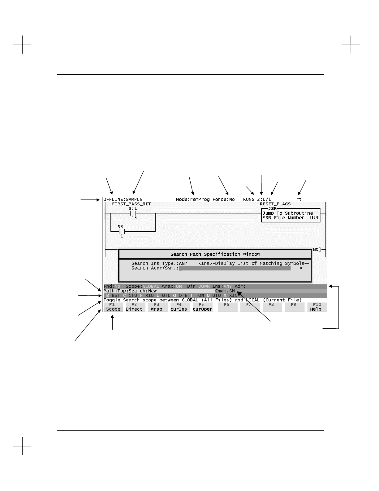
Menu Bar
Status Line
“New.”
rung
screen
This section presents the information available on a typical screen and explains how to
navigate within the software.
Introduction
Screen Layout
Command/Menu
Level. Current
position in menu
structure. The path
shown on this
screen indicates that
from the top menu
bar, “Search” was
selected and then
Instruction
Shortcut Key
Assignments
(Key List)
Function Key
Help (description
of highlighted
menu item)
offline or online
operation
highlighted
menu item
current project
processor
mode
forcing
status
current
program
Command Portal
keys to reach this
total
number of
rungs
Rung
comment and
page title
attached to
current rung
Search Mode
Configuration
(only appears
when searching)
Items in bold type may be moved or removed from the screen. Refer to Configure
Window Display in Chapter 12 - Customizing PLC-500 A.I.
1-7
Page 19
MicroLogix 1000 and PLC-500 A.I. Series Software Reference
Starting PLC-500 A.I.
To run PLC-500 A.I.:
1. Change to the directory where PLC-500 A.I. has been installed. The default
directory is C:\SLC500. To change the directory, type
CD \SLC500 [Enter]
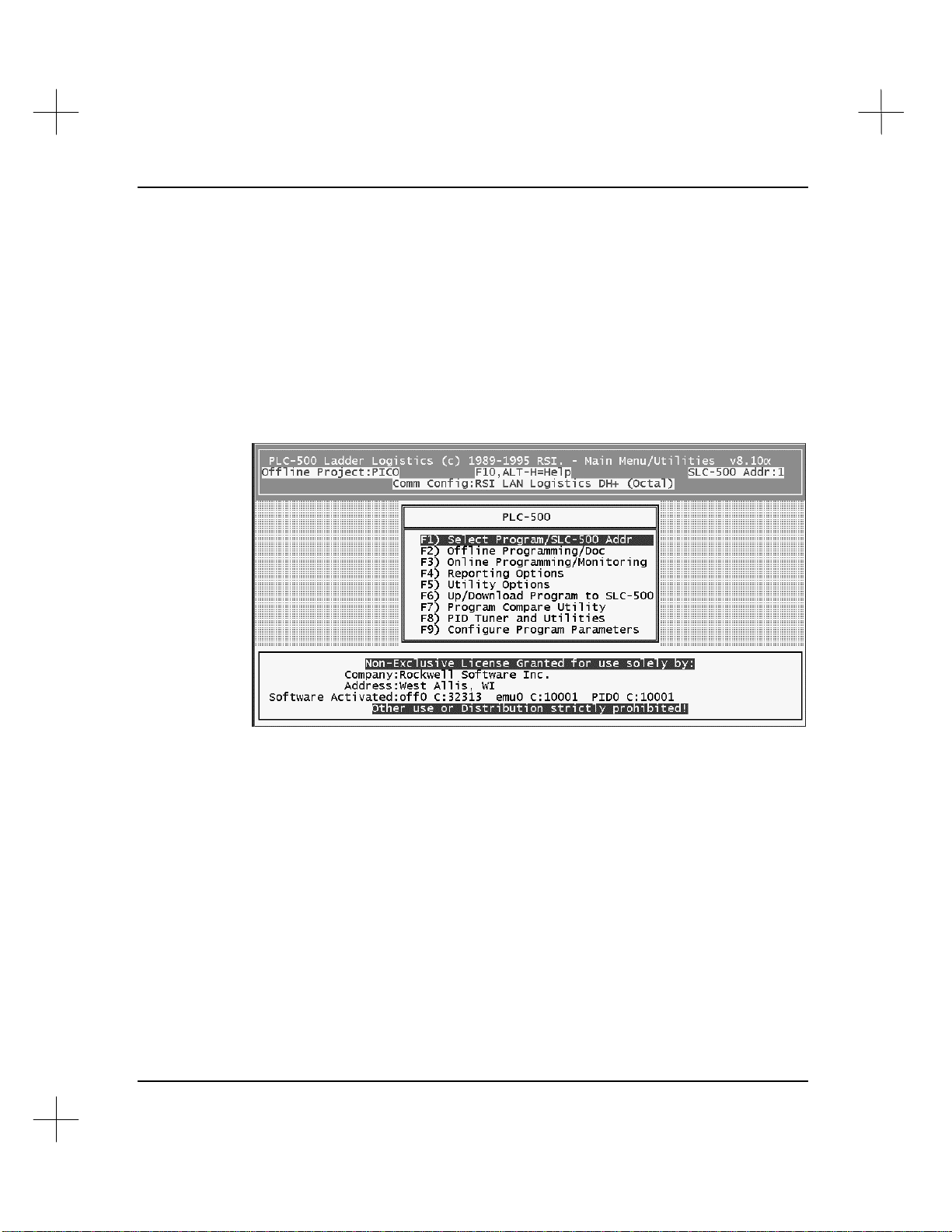
2. Enter the command to run the software. At the DOS prompt, type
AB500
The Main Menu will appear.
1-8
The second line from the top of the screen identifies the currently selected Project, on
the left, and the default network address for the processor, on the right.
The third line from the top of the screen displays the currently selected communication
device followed by the addressing mode of the processor station address on the DH+
(octal), DH-485 (decimal), or Ethernet (decimal) network.
The large box across the lower part of the screen shows your Company name and
Address (city and state or province). The currently activated software modules, the
drives they are installed on, and their serial numbers are displayed immediately below
those lines if the activation files are found on a local or network hard drive. For more
information on installing the software and on activation files, refer to the A.I. Series
Installation Guide.
Page 20
Introduction
Note Company name and address information is taken directly from our customer database.
Please contact Rockwell Software Technical Support at (414) 321-4266 to correct
spelling errors or incorrect registration information.
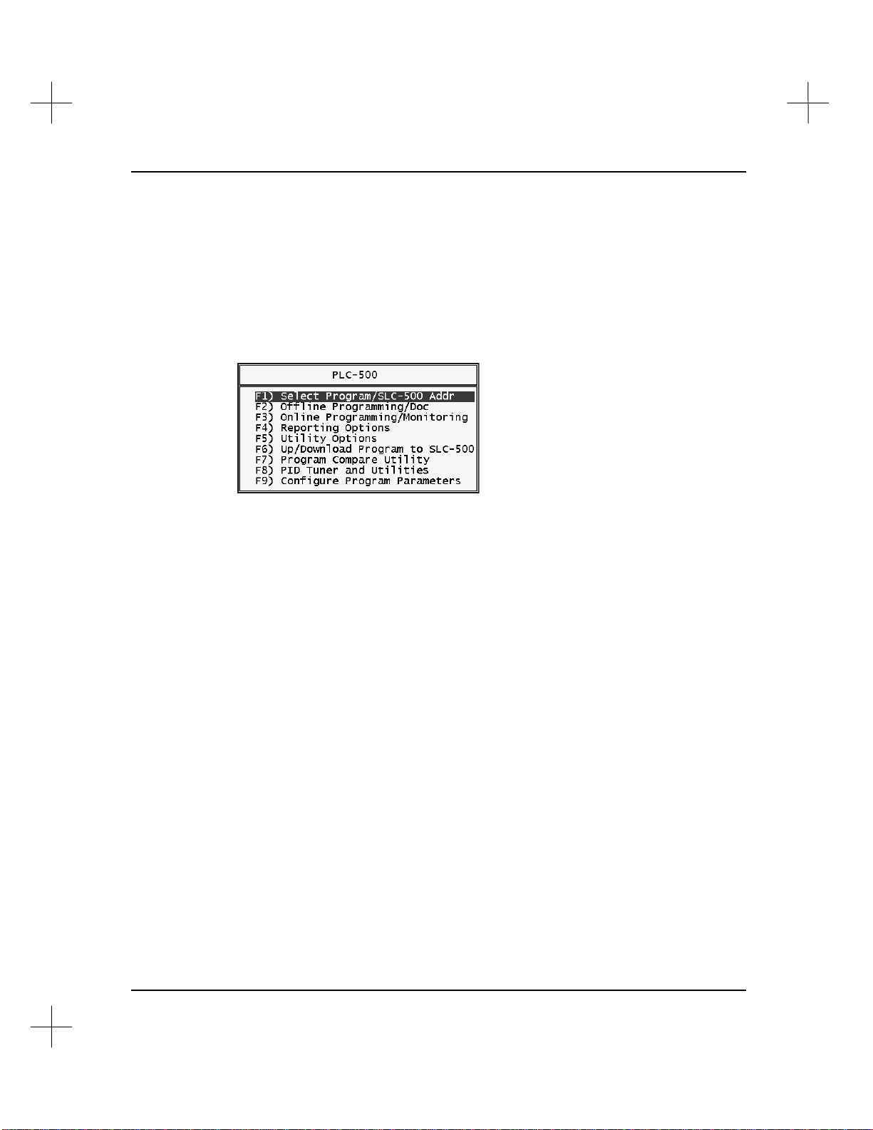
Selecting Menu Options
Menus in PLC-500 A.I. are displayed in a bar along the bottom of the screen as shown
under Screen Layout on page 1-7, or as a list in a box as seen on the Main Menu.
From a menu box, you can select an option in one of two ways:
• Press the function key associated with the desired option. For example, to select
Reporting Options from the menu above, press [F4].
• Use the arrow keys on your keyboard to move the highlighting to the desired
option, then press [Enter].
From a menu bar at the bottom of the screen, you can select an option in one of two
ways:
• Press the function key associated with the desired option. For example, to select
Help from the screen on the previous page, press [F10].
• Use the tab key on your keyboard to move the highlighting to the desired option,
then press [Enter].
To exit a menu (and move backwards through the menu structure) press [Esc].
1-9
Page 21

MicroLogix 1000 and PLC-500 A.I. Series Software Reference
Using the Command Portal to Move Within PLC-500 A.I.
The Command Portal provides a quick way of moving around within the PLC-500 A.I.
ladder editor. Notice on the screen on page 1-7 that each item on the function key
menu bar is in lower case except for one letter. This letter can be used in the Command
Portal to access that menu option.
Press [.] to access the Command Portal. A box will appear on the screen in which you
can type the letters corresponding to the menu bar items you want to select. Press
[Enter] to issue the command.
For example, you can access the data table memory map function any time you are
editing a project by typing .UM [Enter].
The Key Command Guide supplied with PLC-500 A.I. details the Command Portal
keys.
Shortcut Keys
Several key combinations allow you to move quickly from one feature of PLC-500 A.I.
to another.
1-10
Function Key Combination
display Program File list
display Data Table File list
toggle bit on/off
program key assignments (also
obtain instruction help)
display previous program file
change processor mode
access Display menu
access Note editor
force monitor
access user defined help
system information screen
display next program file
access Tag functions
[Shift-F1]
[Shift-F2]
[Shift-F5]
[Shift-F10]
[Alt- –] (dash)
[Alt-C]
[Alt-D]
[Alt-E]
[Alt-F]
[Alt-H]
[Alt-I]
[Alt-N]
[Alt-T]
Page 22

Context Sensitive Help
!
When you are using any Rockwell Software A.I. series product and wonder what to do
next, try pressing [F10]. The Context Sensitive Help system will display information
about where you are in the software and what your options are.
In some parts of the software, [F10] is used for some other function. In those
situations, [Ctrl-F10] is the help key.
When Help is displayed, use the [PgUp] and [PgDn] keys to move through the pages.
Press [Esc] to exit from the help system.
Exiting to DOS Temporarily
You can temporarily leave PLC-500 A.I. to go into DOS. This allows you to run other
DOS applications and utilities without closing PLC-500 A.I.
To shell into DOS:
1. From the Main Menu, select [F5] Utility Options. The system displays the Utility
Options menu.
Introduction
2. From this menu, select 12 Exit to DOS Temporarily. The system goes into DOS,
keeping PLC-500 A.I. resident.
Note To select menu options beyond [F9], use the cursor motion keys to highlight the option,
and press [Enter].
To return to PLC-500 A.I., type exit and press [Enter] at any DOS prompt.
Note You can also shell out to DOS while in the Offline or Online editor by selecting [F6]
Utility, [F9] Util2, [F1] Exit or by using the Command Portal keys .UUE.
Do not load any Terminate and Stay Resident programs (TSRs) while in the
temporary DOS session. This includes network shells.
Do not modify or delete any PLC-500 A.I. files during the temporary DOS session.
Do not turn off or reboot the computer during the temporary DOS session.
1-11
Page 23

MicroLogix 1000 and PLC-500 A.I. Series Software Reference
You can prevent users from exiting temporarily to DOS by setting the NOEXITTODOS
environment variable. See the A.I. Series Installation Guide for a complete list of
environment variables.
Add the following line to a batch file that starts PLC-500 A.I. or to the
AUTOEXEC.BAT file. If you only want to prevent exiting to DOS for one use, type
the line at the DOS prompt before starting PLC-500 A.I.
SET NOEXITTODOS=1
You can also use the security system to prevent users from exiting temporarily to DOS.
See Chapter 20 - Security System.
1-12
Page 24

PLC-500 A.I. Optional Add-On Modules
Rockwell Software produces the following software packages that operate in
conjunction with PLC-500 A.I. series software. For more information about these
products, contact Rockwell Software or your Rockwell Software distributor.
PID Loop Tuner and Data Acquisition/Monitoring
Tune your SLC 5/02, 5/03, and 5/04 PID loops quickly and easily! The PID Tuner
collects and analyzes data from PID loops, and suggests optimum tuning parameters for
the loops. You can directly download the suggested parameters to the SLC 500
processor. The PID Tuner is available either as an add-on to the SLC 500 software, or
as a stand-alone system with its own menu and database import functions. (Not
available for the MicroLogix 1000 controllers.)
Processor Emulation Module
Run and test your ladder logic without going online! The Processor Emulation module
allows your computer to run the ladder logic without a programmable controller. (Not
available for the MicroLogix 1000 controllers.)
Introduction
Other PLC-500 A.I. Compatible Products
The following Rockwell Software products may be used with the PLC-500 A.I. software
or by themselves to simplify operations with the SLC 500. For more information on
these products, call Rockwell Software or your Rockwell Software distributor.
WINtelligent LINX™
Use Windows applications to monitor and write data to the SLC 500 data table!
WINtelligent LINX uses the Windows Dynamic Data Exchange (DDE) to transfer data
between SLC 500's (or PLC-5's, PLC-2's and PLC-3's) and DDE compatible Windows
applications, such as Microsoft Excel.
1-13
Page 25

MicroLogix 1000 and PLC-500 A.I. Series Software Reference
Complete A.I. Series Product Line
Do you use other Allen-Bradley PLC platforms? Rockwell Software produces versions
of the A.I. Series software for PLC-2 & 1774-PLC, PLC-3 & 3/10, PLC-5, and PLC5/250, each with the same features as the SLC 500 product. Contact your Rockwell
Software distributor or Rockwell Software Inc. for more information.
1-14
Page 26

Support for Your Rockwell Software Product
When you purchase a software package from Rockwell Software, you also purchase the
support services of the entire Rockwell Software staff. We understand the expense of
"down time," and we'll do whatever we can to solve any software (and yes, sometimes
hardware) problems you might encounter.
For information on product support and updates, please refer to the Product Support
Guide or call the Rockwell Software Support Information Line at (414) 321-4266.
Introduction
1-15
Page 27

MicroLogix 1000 and PLC-500 A.I. Series Software Reference
Necessary Equipment
The following equipment is necessary to run the PLC-500 A.I. Series Ladder Logistics
Software. This information is written for running your A.I. Series software in DOS.
Exceptions and considerations for running under Windows™ operating systems
(Windows, Windows 95, and Windows NT™) are noted.
Basic Equipment
• IBM 386, 486, Pentium, or compatible
• DOS 5.0 or greater
• 4 M of RAM (16 M of RAM under Windows 95)
• One floppy and one hard disk drive
• Monochrome, EGA or VGA display
Note To run PLC-500 A.I. version 8.xx in monochrome, you must set an environment
variable. Add the following command to your autoexec.bat file or to a batch file that
starts PLC-500 A.I.
SET FORCEMONO=1
At least 3 M of Extended Memory must be available after loading all TSR’s and
device drivers, otherwise PLC-500 A.I. will run extremely slowly and some modules
!
Note If you are running under a Windows operating systems, be sure to shell to DOS to
(Online and Reporting) will return errors.
check your free memory.
Optional Equipment
• Printer (Epson compatibles and PCL laser printers, such as the HP Laserjet, are
recommended)
• Special video cards. Video drivers are supplied to take advantage of specific video
hardware for enhanced ladder logic display. These include:
§ EVEREX Micro Enhancer Deluxe EGA
§ Video 7 VGA
§ Paradise/ALR VGA Professional Card
1-16
Page 28

§ ATI VGA WONDER
§ ATI Graphic Solution Card - Hercules Mode
§ Orchid ProDesigner VGA/Plus
Introduction
1-17
Page 29

MicroLogix 1000 and PLC-500 A.I. Series Software Reference
System Configuration
The following sections discuss the steps necessary to assure smooth software start-up
and operation. This information is written for running your A.I. Series software in
DOS. Exceptions and considerations for running under Windows™ operating systems
(Windows, Windows 95, and Windows NT™) are noted.
AUTOEXEC.BAT File
There are no required statements in the AUTOEXEC.BAT file. If you want to start the
PLC-500 A.I. software automatically when your computer is restarted, or to start the
software from a different batch file, make sure you include the following statements in
the batch file:
Statement Function
c:
CD\SLC500
AB500
Change to the drive where PLC-500 A.I. is
installed
Change to the directory where PLC-500 A.I. is
installed
Start PLC-500 A.I. (at the main menu)
1-18
You can also include a statement in the batch file that sets an environment variable
which places user configuration files in a directory other than the SLC500 directory.
This statement is required in multi-user and network installations.
The statement is:
SET PLCLL=C:\USER1
where C:\USER1 is an existing subdirectory. If you use the environment variable,
copy the file SLC5LL.DEF from the product directory (usually \SLC500) to the
specified directory. This loads the default status file word/bit descriptions
automatically when a new database is loaded. Refer to the A.I. Series Installation
Guide for more information on network and multi-user installation.
Page 30

If your system has 4 M of RAM (at least 8 M if using a Windows operating system),
you can add the following line to your AUTOEXEC.BAT file to improve software
performance.
C:\DOS\SMARTDRV.EXE 1024
Once you have added this line and rebooted your computer, check to make sure that at
least 3M of RAM is free. Type MEM [Enter] at the DOS prompt. Look at the number
under the “Free” column for “Extended (XMS)” memory; it should be greater than or
equal to 3072. If it is less than 3072, decrease the RAM that is being allocated to
SMARTDRV.EXE, reboot, and check again. (For additional information on
SMARTDRV.EXE, see your DOS manual or type help smartdrv.exe at the DOS
prompt.)
CONFIG.SYS File
This file must be in the root directory of the drive that your computer boots from
(typically drive “C” for a hard disk based system). This file is not needed if you are
using Windows 95 or NT.
The CONFIG.SYS file should contain the following statements:
Introduction
DEVICE=C:\DOS\HIMEM.SYS
DEVICE=C:\DOS\EMM386.EXE NOEMS
DOS=HIGH
FILES=40
BUFFERS=30
Note The path in your DEVICE statements may be slightly different if you are running
Windows, for example, C:\WINDOWS\HIMEM.SYS or C:\WFW\HIMEM.SYS.
Specifying quantities greater than those listed above are generally acceptable, but
additional buffers will subtract from your available RAM. Use a text editor to modify
or create the CONFIG.SYS file if necessary.
Note If the CONFIG.SYS file is added or edited, you will need to “warm boot” your
computer (press [Ctrl-Alt-Del]) before the changes take effect.
1-19
Page 31

MicroLogix 1000 and PLC-500 A.I. Series Software Reference
RAM Considerations
PLC-500 A.I. requires an 80386 or faster processor and at least 3 M of extended
memory (XMS) free. If your system has less than 3 M of available RAM, the software
will be forced to use a swap file on your hard drive, which slows down many software
operations considerably.
Note If you are running under Windows, be sure to shell to DOS to check your free memory.
An ideal system would contain at least 8 M of RAM, where at least 3 M of RAM is
available after allocating some memory to a disk cache (such as MS-DOS’s Smartdrv).
The version of MS-DOS on your system also affects the amount of available RAM.
Although the software can run on MS-DOS 4.01 and 5.0, consider MS-DOS 6.0 as the
minimum version due to its advanced memory management features.
PLC-500 A.I. no longer has a minimum conventional RAM requirement of about
580K. As long as you have more than 500K free conventional memory (and at least 3
M of XMS memory free), you will be able to run the software without memory errors.
1-20
Page 32

About Memory Managers
A memory manager is a software program that manages the use of memory in your
computer. If your computer has any expanded memory (EMS) or extended memory
(XMS) installed, you may be using some sort of memory manager.
In certain configurations, some memory managers may conflict with the following DH-
485 and DH+ network interface cards.
• Allen-Bradley 1784-KT
• Allen-Bradley 1784-KTX
• Allen-Bradley 1784-KL
• Allen-Bradley 1784-KT2
• Allen-Bradley 1784-KR
• Allen-Bradley 1784-PCMK
• S-S Technologies, Inc. 5136-SD
• S-S Technologies, Inc. 5136-SD2
Introduction
This section describes how to avoid these conflicts.
386MAX.SYS
386MAX.SYS is a memory manager produced by Qualitas, Inc.
There is an easy method to avoiding 386MAX conflicts with the interface cards.
386MAX is shipped with a program called MAXIMIZE.EXE. This program examines
your computer and makes certain that it won’t create memory conflicts with your
existing hardware. If you use MAXIMIZE.EXE to configure 386MAX, you should
have no conflicts with your interface. See the 386MAX User’s Guide for more details.
QEMM.SYS
QEMM.SYS is a memory manager produced by Quarterdeck, Inc.
1-21
Page 33

MicroLogix 1000 and PLC-500 A.I. Series Software Reference
The command line in your CONFIG.SYS file which starts QEMM.SYS can be
modified to avoid your DH-485 and DH+ interface cards. Use the “EXCLUDE”
statement to tell QEMM.SYS which addresses to avoid. An example of a command
which avoids an Allen-Bradley 1784-KT with a memory address of D800 is shown
below.
DEVICE=C:\QEMM\QEMM.SYS EXCLUDE=DB00-DBFF
A second example shows a command which avoids the Allen-Bradley 1784-KL in the
A-B T47 Programming Terminal.
DEVICE=C:\QEMM\QEMM.SYS EXCLUDE=E000-E0FF
EMM386.EXE
EMM386.EXE is a memory manager provided with MS-DOS.
The command line in your CONFIG.SYS file which starts EMM386.EXE can be
modified to avoid your DH-485 and DH+ interface cards. Use the “EXCLUDE”
statement to tell EMM386.EXE which addresses to avoid. An example of a command
which avoids an Allen-Bradley 1784-KT with a memory address of D800 is shown
below.
1-22
DEVICE=C:\DOS\EMM386.EXE EXCLUDE=DB00-DBFF
A second example shows a command which avoids the Allen-Bradley 1784-KL in the
A-B T47 Programming Terminal.
DEVICE=C:\DOS\EMM386.EXE EXCLUDE=E000-E0FF
Page 34

Communications Hardware
You can transfer programs to and from the SLC 500 and monitor online operations
using a Rockwell Software product and one of the following protocols depending on
your SLC 500 processor: DH-485, DH+, or RS-232. Refer to Allen-Bradley’s data
sheets or hardware manuals to determine valid network configurations.
For information on configuring communications hardware to operate with
PLC-500 A.I., refer to Chapter 15 - Configuration for Online Communications.
NT Users: Only serial drivers (except the 1747-PIC) will work when running PLC-
500 A.I. under Windows NT. RSI is working on a version of the software that will
contain special drivers to communicate through RSLinx™. This will allow you to
communicate using any of the drivers available with RSLinx.
Introduction
1-23
Page 35

2 Handling Project Files
There is a specific order of events to follow when you create a ladder logic program
using PLC-500 A.I. This chapter will tell you how to accomplish step 1 below.
1. Create a project. Projects are the set of files having to do with a ladder program.
There are a variety of files in a project, but PLC-500 A.I. creates the files
automatically, whenever you need them. Creating a project is as simple as giving
it a name that PLC-500 A.I. can use to refer to the files.
2. Configure the processor type and I/O. This process tells PLC-500 A.I. what type of
programmable controller module and I/O modules you are using, and allows PLC500 A.I. to address the I/O points. The features available in the software vary with
processor type, so defining the processor type is very important. Chapter 3 -
Configuring the PLC-500 CPU and I/O Modules discusses this step.
3. Enter and document the ladder program for the project. This is the actual program
you will use in your SLC 500 processor. This step is discussed in Chapter 6 -
Creating and Editing Ladder Logic and in Chapter 8 - Adding Descriptive Text to
Ladder Logic.
The File Selector feature of PLC-500 A.I. provides a tool for handling files. This
chapter will explain how to use the File Selector to create a new project file, select an
existing project, and use file utilities for such functions as deleting and backing up files.
Page 36

MicroLogix 1000 and PLC-500 A.I. Series Software Reference
Components of a Project File
Notes on terminology: The term processor file used in this manual is equivalent to the
term program used in Hand-Held Terminal (HHT) displays. Both of these terms mean
the collective “program files” and “data files” created within the particular processor
file name or program name. The term processor file does not include the description
database files.
Most of the operations you perform with a SLC-500 processor involve a project file. A
project file consists of the database files and the processor files. Processor files consist
of program files and data files.
Project
Processor File
.CFG
.ATT
.PRF
.NAM
.ACH
Program
Files
Data
Files
Database Files
.DSC
.ADR
.SYM
.RPD
.RPI
.XRF
.XRI
Refer to Appendix A - PLC-500 A.I. File Extensions for information on the file
extensions shown in the diagram above.
2-2
Page 37

Program Files
Program files contain controller information, the main ladder program, and any
subroutine programs. The first three program files are required for each project:
• The system program file (file 0) is always included. It contains various system
related information and user-programmed information such as processor type, I/O
configuration, processor file name and password.
• File 1 is reserved for future use.
• The main ladder program file (file 2) is always included. It contains user-
programmed instructions defining how the controller is to operate.
• Subroutine ladder program files (files 3 - 255) are created by the user and
activated or “called” from the main ladder program using subroutine instructions.
(This does not apply to the MicroLogix controller. See below.)
The Fault Routine, Discrete I/O Interrupts, STI Interrupts, and I/O Event Driven
Interrupts require subroutine program files.
MicroLogix Controller Differences
The system program (file 0) and main ladder program (file 2) are as listed above. Files
3 and higher are listed below:
• The user error fault routine (file 3) is executed when a recoverable fault occurs.
• The high-speed counter interrupt (file 4) executes when an HSC interrupt occurs.
This file can also be used for a subroutine ladder program.
• The selectable timed interrupt (file 5) executes when an STI occurs. This file
can also be used for a subroutine ladder program.
• Subroutine ladder program files (files 6-15) are used according to subroutine
instructions residing in the main ladder program file or other subroutine files.
Handling Project Files
Data Files
These files contain the data associated with the instructions in the ladder program files.
In addition, these files store information concerning processor operation. You can also
use the files to store “recipes” and look-up tables if needed. Each project can contain
up to 256 data files (except for MicroLogix). These files are organized by the type of
data they contain.
2-3
Page 38

MicroLogix 1000 and PLC-500 A.I. Series Software Reference
MicroLogix
The MicroLogix controller provides 8 default data files (0-7) and no user-defined data
files. Data file types are listed below.
Fixed, SLC 5/01, SLC 5/02, and 5/03 OS300
The first eight data files (0-7) have default types. File 8 is reserved for future use. You
designate the file types for the remainder of the files (9-255).
SLC 5/03 OS301 and up, and SLC 5/04
The first nine data files (0-8) have default types. You designate the file types for the
remainder of the files (9-255).
Data File Types
The default data file types are:
• O Output (file 0): This file stores the state of the output terminals for the
controller.
• I Input (file 1): This file stores the status of the input terminals for the controller.
• S Status (file 2): This file stores controller operation information. This file is
useful for troubleshooting controller and program operation.
• B Binary or Bit (file 3): This file is used for internal relay logic storage.
• T Timer (file 4): This file stores the timer accumulated and preset values and
status bits.
• C Counter (file 5): This file stores the counter accumulated and preset values and
the status bits.
• R Control (file 6): This file stores the length, pointer position, and status bits for
specific instructions such as shift registers and sequencers.
• N Integer (file 7): This file is used to store numeric values or bit information.
Values range from -32768 to 32767.
2-4
• F Floating Point (file 8): Only SLC 5/03 OS301 and SLC 5/04 OS400 processors
and higher use floating point. This file stores single precision non-extended 32-bit
numbers. The valid range is ±1.1754944e
-38
to ±3.40282347e
+38
.
Page 39

• User-Defined (file 9-255): These files are user-defined as bit, timer, counter,
Database Files
The database files contain descriptions you have added to your ladder logic. These
include instruction descriptions, rung descriptions, instruction symbols, and page titles.
Processor Files
A processor file contains the collection of program files and data files created under a
particular processor file name. As such, it contains all the instructions, data, and
configuration information pertaining to a user program. We refer to the program and
data files separately, however, they are both contained in the .ACH file.
The processor file is a transferable unit. It can be located in the Rockwell Software
programming terminal (or in the Hand-Held Terminal). Processor files residing in a
programming terminal can be transferred to/from a MicroLogix 1000, SLC 500, 5/01,
5/02, 5/03, or 5/04 processor, or to/from a memory module (i.e., EEPROM) located in
the SLC 500 processor.
Handling Project Files
control, and integer data storage. For SLC 5/03 OS301 and SLC 5/04 OS400
processors and higher, floating point, string (ST), and ASCII (A) files are also
supported. In addition, file 9 is specifically available as a Communication
Interface File. (These files are not available on the MicroLogix controller.)
Processor FileProcessor FileProcessor File
Terminal
Memory ModuleSLC 500 ProcessorRockwell Software
Processor files residing in the Hand-Held Terminal can only be transferred to or from a
SLC 500, 5/01, or 5/02 processor or to or from a memory module located in one of
those processors. You cannot use a Hand-Held Terminal to transfer processor files to
or from an SLC 5/03 or 5/04 processor. You can use a Hand Held Programmer to
transfer files to and from a MicroLogix controller.
2-5
Page 40

MicroLogix 1000 and PLC-500 A.I. Series Software Reference
Project
A project includes the processor file with its components and the database files. Only
the processor file is transferable. The database files cannot be downloaded to the
processor.
2-6
Page 41

Creating a New Project
Access the File Selector to create a new project:
1. From the Main Menu, select [F1] Select Program/SLC-500 Addr. The File
Selector appears.
Handling Project Files
The File Selector consists of two windows. The left window shows the files in the
current directory, and the right window lists the current directory, search
specification, and the options available to you.
2. Make sure the Current Directory field shows the directory in which you would like
to store your new file. If not, see Current Directory on page 2-13 for directions on
changing the current directory.
2-7
Page 42

MicroLogix 1000 and PLC-500 A.I. Series Software Reference
3. Press [Ins] to create a new project file. A window appears, prompting you for a
project name.
4. Type a name for the project, and press [Enter] to accept the name. The name for
the project must be eight characters or fewer in length, and must not contain
characters that violate standard DOS naming conventions (/ \ . : or a blank space).
Do not type a file extension. The utility automatically adds the appropriate file
extension to the filename, and places it in the Current Directory.
Note If you want to use your file later with Allen-Bradley APS software, use only
alphanumeric (A-Z, 0-9) and underscores (_) in your filenames. APS software will not
recognize filenames containing other characters.
5. Set the SLC 500 station address for the project. After you name a new project with
the File Selector, PLC-500 A.I. asks you to identify the address of the SLC 500 for
which you are creating this project.
This is the DH-485 network node number or, for SLC 5/04 processors, the DH+
network node number. To set the station address:
• backspace to remove the default of 1
• type the address.
2-8
Page 43

• press [Enter] to accept the address. The software will return to the Main
Menu.
The project files won’t actually be created until you edit (go Offline with) the project
(see Editing a New Project below).
If you are editing offline, you can change the SLC 500 address at any time while
editing the ladder.
Modifying the SLC 500 Address
The SLC 500 address shown in the upper right corner of the File Selector screen shows
the default destination DH-485 (or DH+) node address for the currently selected
working project. When you go online with that project, PLC-500 A.I. begins looking
for a SLC 500 at the address you select. If it does not find a SLC 500 at that address,
PLC-500 A.I. displays the Who Active screen, and allows you to choose a different
SLC 500 address for the project. This address is then saved as the new default.
To modify the SLC 500 address for a project:
1. With the File Selector utility displayed on your screen, highlight the desired file.
Handling Project Files
2. Select [F1] Modify Addr.
3. The utility prompts you to enter a SLC 500 station address. The current station
address is displayed in the prompt. Enter the new address, 0-31 decimal. (With a
SLC 5/04 processor, you can use DH+ addresses 0-77 octal, but you must configure
the interface before you can modify the address. See below.) Press [Enter] to
accept the address.
Configuring the Interface for DH+ Communication With a SLC 5/04
If you want to select a DH+ address higher than 31 (from 0-77) for your SLC 5/04
processor, you must first configure the interface.
1. From the Main Menu, select [F9] Configure Program Parameters.
2. Select [F1] Communication Hardware.
3. Select [F2] Interface Hardware Type.
4. Select [F3] DH+ Communication Devices, then select a driver.
2-9
Page 44

MicroLogix 1000 and PLC-500 A.I. Series Software Reference
5. Press [Esc]. You will be asked to save the configuration. Select [F1] Yes.
Now when you modify the address as described above, the software will prompt you for
a DH+ station address between 0 and 77 (octal).
Editing a New Project
The first time you attempt to edit a new project with [F2] Offline Programming/Doc
on the Main Menu PLC-500 A.I. will display the prompt shown below.
Select [F1] Yes to create the project files. PLC-500 A.I. prompts you to select the
processor type. See Chapter 3 -Configuring the PLC-500 CPU and I/O Modules for
information on configuring the system. If you select [F5] No, the new program files are
not created and the File Selector utility appears. See Selecting a Project File on the
following page for information on using the File Selector to choose a different project
file.
2-10
Page 45

Selecting a Project File
Use the File Selector to choose an existing file. Simply highlight the file using the
arrow keys and press [Enter]. You may also highlight files by typing in the name from
the keyboard. For instance, typing the letter “M” will highlight the first file in the list
beginning with the letter “M.” Entering subsequent letters in a name will find the file
matching the name you typed.
The rest of this section describes in more detail how to navigate File Selector to find
your file if you do not see it listed initially.
File List
From the Main Menu, select [F1] Select Program/SLC-500 Addr. The File Selector
appears.
Handling Project Files
The File Selector appears as two windows. The right window lists the current
directory, search specification, and the options available to you, and the left window
shows the files in the current directory. The list shows only those files with the
filename extension shown in the Search Specification.
Note The Search Specification cannot be changed by the user. See the section on Search
Specification below.
2-11
Page 46

MicroLogix 1000 and PLC-500 A.I. Series Software Reference
The file list shows the filename, the size of the file, and the date the file was last
modified. If you are selecting a project file (*.ACH), the file list also shows a SLC 500
address for the project; otherwise, the file list shows the time when the file was last
saved.
Three items in the file list control which directory is displayed:
1. MAKE NEW DIRECTORY/CHANGE DRIVE: Select this item to change the
current drive and/or directory. If no file is selected, this is usually the default.
When you press [Enter] with this line highlighted, a prompt will appear for a new
subdirectory. If you type a new name at this point, the software will create a
subdirectory (not a project) with that name.
2. . <DIR> CURRENT DIRECTORY: Select this item to redisplay the contents of
the current directory. Use this when you are reading from a floppy disk drive and
you change disks, or when you are on a networked drive and the contents of the
drive are changing. If this option is not shown, then the default directory in the
right-hand window does not exist.
3. . . <DIR> PARENT DIRECTORY: Select this to move up one level in the
directory structure.
Search Specification
The Search Specification indicates the file extension of the files in the list. All of the
files in the list on the left of the screen will have this extension.
You cannot change the Search Specification; it is determined by how the File Selector
screen was called. For instance, when you call the File Selector from the Main Menu
with [F1] Select Program/SLC 500 Addr, the Search Specification looks for .ACH
files. When you select a program database for editing, PLC-500 A.I. looks for .ACH
files, because the .ACH file uniquely identifies the project, and thus the database.
When you select a printer configuration, PLC-500 A.I. calls the File Selector screen. In
this case, the Search Specification looks for a .RCF file.
2-12
Page 47

Handling Project Files
Current Directory
The Current Directory field in the right window shows the directory where the File
Selector is searching for files. The default Current Directory is the directory where you
store your program files.
There are two ways to change the current directory. You can directly specify the
pathname, or you can select it by cursoring through the directory structure using the
..<DIR> Parent Directory or highlighting a directory name on the left and pressing
[Enter].
Note To use files from a different disk drive, you must directly specify the path to the drive.
For instance, to change to drive B:, you must specify the root directory as B:. You
can then cursor through the directory structure of B: to find the files.
To directly specify a pathname:
1. Use the [Home] key (or the up arrow key) to move the highlight bar in the left
window to MAKE NEW DIRECTORY/CHANGE DRIVE.
2. Press [Enter]. The File Selector prompts you to enter a new pathname.
3. Type the pathname, and press [Enter]. If the directory exists, the File Selector
shows the files in that directory. If the directory does not exist, the File Selector
creates it.
To select a directory to change to:
1. Using the up and down arrow keys, move the highlight bar in the left window to
.. <DIR> PARENT DIRECTORY.
2. Press [Enter]. The left window refreshes, showing the files in the directory
directly above the old directory. Notice the old directory is shown in the file list
with <DIR> next to the directory name.
3. You can move up and down through the directory structure by selecting parent
directories and subdirectories. Subdirectories are indicated by a <DIR> after their
name on the left. When you locate the file you want, move the highlight bar to the
file name, and press [Enter] to select the file.
2-13
Page 48

MicroLogix 1000 and PLC-500 A.I. Series Software Reference
Sorting the File List
You can change the order in which files appear in the file list. You can sort by
file/directory name, file extension, the date the file was last modified, or the file size.
To toggle the order, press [F9] Sort Mode.
To change the sort mode:
1. With the File Selector utility displayed on your screen, press [F9].
2. The system displays the new sort mode and re-sorts the files in the list. Continue
pressing [F9] until the files are sorted the way you want them.
The available sort modes are:
Sort mode Description
Name Sort alphabetically by file name.
Ext Sort by extension. In most cases there are directories and only one
type of file displayed. Since directories usually don’t have extensions,
they are listed first.
Date Sort by file date and time. Sorts the files so the oldest appears at the
top.
Size Sort the files by size. Since a directory doesn’t have a file size per-se,
directories are listed first.
2-14
Page 49

File Utilities
When you use the File Selector utility from the Main Menu or from the Reporting
Options menu, the File Selector gives you access to several file utilities. Use these
utilities for copying, renaming, deleting, backing up, and restoring files.
Copying Files
To copy project files:
1. With the File Selector utility screen displayed, highlight the project name you want
to copy. If this is the only file you want to copy, go on to step 2. If you want to
copy more than one ladder/database, press [F5] Mark File for Copy. Highlight
the next file and press [F5] Mark File for Copy again. Repeat for the remainder
of the projects you want to copy.
2. Press [Tab]. The utility presents you with a list of file utilities.
Handling Project Files
3. Select [F1] Copy file(s).
4. The utility asks you which files you want to copy: the processor memory files,
description database files, or all of the files for the project. Select the type of files
you want to copy.
2-15
Page 50

MicroLogix 1000 and PLC-500 A.I. Series Software Reference
5. The utility asks you to specify a pathname for the copied files. Type the pathname,
and press [Enter]. As the utility copies the files, it shows you the name of the file
currently being copied.
Note If the name you enter ends with a backslash (\), or if you have highlighted multiple
files, the system considers the name you entered to be a directory name. Otherwise,
the name you enter is used as the name of the new file. For example, if you select
OLDPROG.ACH and copy to …\NEWPROG, you end up with NEWPROG.ACH. If you
copy it to …\NEWPROG\, you get …\NEWPROG\OLDPROG.ACH. If you mark
OLDPROG1.ACH and OLDPROG2.ACH and copy them to either …\NEWPROG or
…\NEWPROG\, you will end up with …\NEWPROG\OLDPROG1.ACH and
…\NEWPROG\OLDPROG2.ACH.
Renaming Files
To rename project files:
1. With the File Selector utility screen displayed, highlight the project name you want
to rename. Press [F5] Mark File for Copy to perform the operation on more than
one ladder/database. Repeat this step for the remainder of the projects you want to
rename.
2-16
2. Press [Tab]. The utility presents you with a list of file utilities.
3. Select [F2] Rename file(s).
4. The utility asks you which files you want to rename: the processor memory files,
description database files, or all of the files for the project. Select the type of files
you want to rename. The utility asks you to specify a new name for the selected
files.
(See the note above under Copying Files for information on specifying file names and
directories.)
Page 51

Handling Project Files
Deleting Files
To selectively delete project files:
1. With the File Selector utility screen displayed, highlight the project name you want
to delete. Press [F5] Mark File for Copy. Repeat this step for the remainder of
the projects you want to delete.
2. Press [Tab]. The utility presents you with a list of file utilities.
3. Select [F3] Delete file(s).
4. The utility asks you which files you want to delete: the processor memory files,
description database files, or all of the files for the project. Select the type of files
you want to delete. The utility prompts you before deleting each of the files
associated with the project.
Note If you want to delete only one project file, you can highlight the file with the File
Selector, and press [Del]. This deletes the entire project, both processor memory and
the description database. The system warns you that you are about to delete the files.
Backing Up Files
Backup files are now stored in a compressed format (so fewer diskettes are needed), but
early versions of PLC-500 A.I. used an uncompressed format. The new restore function
is capable of restoring new or old backups. The old restore function cannot restore
backups made with software versions 6.0 and higher.
Calculating Number of Disks for a Backup
Backups sometimes require several floppy disks to hold all of the files. To perform a
backup, you need to have enough formatted disks to hold all of the files. You cannot
stop a backup part of the way through to format more disks, so PLC-500 A.I. has a
utility that calculates the number of disks you will need to back up your files. (Skip this
step if you are backing up to a network drive or hard disk.)
To calculate the number of disks you will need for a backup:
1. With the File Selector utility screen displayed, highlight the project name you want
to back up. If you want to backup multiple projects, highlight each project and
press [F5] Mark File for Copy to mark each one.
2-17
Page 52

MicroLogix 1000 and PLC-500 A.I. Series Software Reference
2. Press [Tab]. The utility presents you with a list of file utilities.
3. Select [F7] Calculate Disks Required for Backup. The utility asks you which
files you want to back up: the processor memory files, description database files, or
all of the files for the project.
4. Select the file type you want to back up. The utility calculates the number of disks
you will need to back up the files you selected.
The utility calculates the number of disks for four different disk formats:
• 5-1/4 inch, 360KB
• 5-1/4 inch, 1.2MB
• 3-1/2 inch, 720KB
• 3-1/2 inch, 1.4MB
The number of disks is displayed as a range. For example, “1-2” would mean that you
will need one or two disks to perform the backup.
Formatting Disks for Backups
(Skip this step if you are backing up to a network drive or a hard disk.)
Before you can use a floppy disk, it must be prepared to accept data. The process of
preparing the disk is called formatting. PLC-500 A.I. contains a utility that allows you
to format disks.
Note The formatting utility in PLC-500 A.I. is the same as the DOS format utility run without
switches. You must have a path set up to the directory containing the DOS Format
command or a “spawn error-1” will be displayed.
To format disks:
1. With the File Selector utility screen displayed, press [Tab]. The utility presents
you with a list of file utilities.
2. From the list of utilities, select [F6] Format Disk(s) for Backup. The utility asks
you which drive you want to use to format the disk. For safety reasons, only drives
A: and B: are available for this option. To format disks in drives other than A: or
B:, exit to DOS and use the format command from the DOS prompt.
2-18
Page 53

Backing Up
Handling Project Files
3. Select the floppy drive you want to use for formatting the disk. The utility warns
you that all information on the floppy disk in the drive will be lost. Select [F1]
Yes to continue formatting.
4. The utility prompts you to insert the disk to format in the drive you selected. Insert
the disk, and press [Enter] to begin formatting.
5. The utility formats the disk. When it finishes formatting the disk, the utility asks
you if you want to format another disk. If you answer yes, the utility asks you to
put the next disk into the floppy drive and press [Enter]. Repeat this step until you
format all of the disks you will need for your backup.
To backup project files:
1. With the File Selector utility screen displayed, highlight the project name you want
to backup. If you want to backup multiple projects, highlight each project and
press [F5] Mark File for Copy to mark each one.
2. Press [Tab]. The utility presents you with a list of file utilities.
3. Select [F4] Backup file(s).
4. The utility asks you which files you want to back up: the processor memory files,
description database files, or all of the files for the project. Select the type of files
you want to back up.
5. The utility asks you to select a disk drive for the backup files. Select a disk drive.
Note Versions of PLC-500 A.I. prior to version 7.xx only allowed you to backup to drive A
or B. Now you can backup to any drive—including a network drive or your hard disk.
6. The utility asks you to enter a description of the backed-up files for future
reference. This description is used when you restore files from backup. Type the
description, and press [Enter]. (See Restoring Files.)
2-19
Page 54

MicroLogix 1000 and PLC-500 A.I. Series Software Reference
7. The utility asks you to insert backup disk #1 in the drive you selected, and warns
you that the information in the root directory of the floppy disk will be erased. If
you are backing up to floppy disks, make sure you have a formatted floppy disk in
the disk drive, and enough floppy disks to back up all the files you selected. See
Format Disks for Backup, and Calculating Number of Disks for a Backup, above.
Press [Enter] to begin the backup process.
8. As the utility backs up the project files, it displays the filenames for the files.
When the first disk fills with files, the utility asks you for another disk. This
process continues until all the files you selected are backed up to floppy disk.
Note Backup files are not saved in the DOS backup format. They are saved in a special
archived format. To use the files, you must decompress them using the Restore file(s)
utility. See Restoring Files.
Restoring files
To restore project files from a backup:
1. With the File Selector utility screen displayed, press [Tab]. The utility presents
you with a list of file utilities.
2-20
2. Select [F5] Restore file(s).
3. The utility asks you from which drive you want to restore files. Select the drive
from which you will restore the files.
• If you selected a floppy disk drive, the utility asks you to insert the first backup
disk into the floppy drive you selected. Insert the disk, and press [Enter].
• If you selected [F3] Select Drive/Path, the system prompts you to enter the
directory. Type the drive and directory and press [Enter].
4. The utility displays the description of the backup, and shows you the directory from
which the files were backed up, and the time and date when the backup was made.
The utility also asks you to specify the directory to which you want to restore the
files (the target directory). Type the pathname for the directory, and press [Enter].
Page 55

Handling Project Files
5. The utility begins restoring files to the directory you chose. If a file you are
restoring does not currently exist in the target directory, the utility restores the file
from the disk. If the file already exists in the target directory, the utility prompts
you before overwriting the file. If you answer yes to this prompt, the utility
overwrites the file in the hard disk directory with the backup file. If you answer no
to the prompt, the utility skips restoring that file.
Note If the restore function continually requests a disk without restoring any files, the disks
are probably copies of the backup set. You must restore from an original backup set.
Note Versions of the Restore utility prior to version 6.0 will not be able to read backups
created using the new file-compressing Backup utility.
6. If you are restoring from floppy disks, after all of the files from the first disk are
restored, the utility asks you to insert the next disk into the floppy drive. (If your
backup took only one disk, the restoration is complete.) Insert the next disk into
the drive, and press [Enter]. Repeat this process until all of the files are restored.
2-21
Page 56

MicroLogix 1000 and PLC-500 A.I. Series Software Reference
Accessing the File Selector From the Offline Editor
You can call the File Selector utility from within the offline editor. This utility allows
you to create, recall, and delete projects. You can also change projects without exiting
the offline module, saving the time it takes to load the module into memory.
Command Portal keys
for this function:
.I
Note This implementation of the File Selector is a subset of the File Selector utility you can
To open the File Selector while in the offline module:
1. Go to the topmost menu of the ladder editor.
2. Press [F2] fIle. The File Selector screen appears.
access from the Main Menu. From inside the ladder editor, you cannot run the file
utilities (multiple delete, copy, file backup, etc.).
2-22
Page 57

3 Configuring the SLC 500 CPU and
I/O Modules
When you program your SLC 500 system, you need to configure the following:
• CPU (processor) type
• Rack
• I/O Modules
• Processor Status Bits
The general procedure is:
1. Start the PLC-500 A.I. software.
2. Define a project. See Chapter 2 - Handling Project Files for details.
3. Use the Offline Editor to configure the CPU and I/O. See the following pages for
details.
4. Set the appropriate processor status information. See the following pages for
details.
You will then be ready to program your ladder logic.
Page 58

MicroLogix 1000 and PLC-500 A.I. Series Software Reference
CPU and I/O Configuration
The first time you edit a new project (with [F2] Offline Programming/Doc from the
Main Menu), PLC-500 A.I. displays the SLC 500 Processor Definition Screen for you
to configure your system. If you need to change the configuration for an existing
project, you can access the SLC 500 Processor-I/O Configuration Screen shown below.
Directions given in this chapter are for configuring a new project. Differences for an
existing project are shown in parenthesis ( ).
Command Portal keys
for this function:
.UT or
.DM
Processor Type
3-2
(For an existing project , access the configuration screen from the top menu of the
offline editor by selecting [F6] Utility and then [F3] Type/sr.)
This screen displays the processor type, the racks, and the I/O cards, all of which are
configurable. For the project to run correctly, all the information must reflect the actual
hardware.
The first step in the system configuration is to select the processor type. The processor
type selection affects what other options are available. For example, a modular
processor must have a rack.
Page 59

Configuring the SLC 500 CPU and I/O Modules
To select the processor type:
1. The first time you edit a new project and create the project file, PLC-500 A.I.
displays the following screen.
(To change the processor type for an existing project, access the SLC 500 Processor
- I/O Configuration Screen, as described on page 3-2 . Select [F1] Proctyp. A list
of processor types will appear.)
2. Use the arrow keys to highlight the correct processor. If you are not sure which
processor type you are using, check the label on the side of the processor. In
modular hardware configurations, you will have to pull the processor out of the
rack to see the label.
3. Press [Enter] to select the highlighted processor.
Note If you have a SLC 5/03 or 5/04 processor, you can automatically configure I/O racks
and cards (rather than manually as explained in the two following sections). The
processor type must be selected as described above and the communications device
must be configured and connected. From the Processor I/O Configuration screen,
press [F3] Readcfg.
3-3
Page 60

MicroLogix 1000 and PLC-500 A.I. Series Software Reference
Note If you change the processor configuration for an existing program containing indirect
addresses to a processor that does not support indirect addressing, errors will occur.
PLC-500 A.I. will allow you to save the program with the errors (press [Esc] to
continue when the error list is displayed). Indirect addresses will remain as they were
in the original program. You must edit these addresses before attempting to run the
program with the new processor.
Rack Configuration
After you select the processor type, you must configure the rack or racks. Rack
configuration depends on whether you have a fixed I/O system or a modular system.
Rack configuration is not applicable with a MicroLogix 1000 controller.
Modular Processor
If you have selected a modular processor, you must configure the rack or racks as
follows:
(For an existing project, access the SLC 500 Processor - I/O Configuration Screen, as
described on page 3-2.)
3-4
1. If you have just selected the processor type for a new project, the SLC 500
Processor Definition Screen will be displayed.
2. Select [F2] rack. PLC-500 A.I. prompts you for a rack number.
Page 61

Configuring the SLC 500 CPU and I/O Modules
3. Select [F1] Rack #1, [F2] Rack #2, or [F3] Rack #3. A list of rack types will
appear.
4. Use the arrow keys to highlight the rack type and press [Enter], or just press the
associated function key.
Asterisks (*) will appear next to the slot numbers the rack contains.
To remove a rack from the configuration, follow the steps above, but in step 4 select
[F5] Not Installed.
3-5
Page 62

MicroLogix 1000 and PLC-500 A.I. Series Software Reference
Fixed I/O Processor
If you have selected a fixed I/O CPU, press [F2] rack from the SLC 500 Processor - I/O
Configuration Screen or Definition Screen to toggle the 2-slot expansion rack.
I/O Cards
After you configure the processor and racks, you must configure the I/O cards. In a
fixed I/O system without expansion slots, this step is not necessary; once you have
selected the processor type, the software has the I/O information it needs.
To configure an I/O card:
1. Make sure you are at the SLC 500 Processor Definition Screen (or the I/O
Configuration Screen—see page 3-2 ).
2. Use the arrow keys to highlight the slot that the card occupies. Slots for which
racks have been configured are marked with an asterisk (*).
3. Select [F5] Select. A list of I/O card types will appear.
3-6
4. Use the arrow keys to highlight the I/O card type. You can also type the name of
the card (e.g. IA4) and the highlighting will go to that module.
5. Press [Enter] to select the highlighted I/O card type.
Repeat for each card or slot.
Page 63

Configuring the SLC 500 CPU and I/O Modules
To delete a card from the configuration, highlight the card and select [F6] Delete. You
can place the last line you deleted at the highlighted location by pressing [F7] Undel.
If this location already has a card assigned to it, the previously deleted card will replace
the current one.
[F8] spioCfg brings up the advanced I/O configuration window for the highlighted
card. This only applies to SLC 5/02 processors and higher using certain specialty I/O
cards.
Note The following applies to the Configuration Screen (existing projects) as the [F9]
Monitor key is unavailable on the Definition Screen:
You can also enter descriptions or device assignments for I/O points on discrete
modules. To enter these descriptions:
1. Highlight the card. Press [F9] Monitor to display the I/O points on the card.
2. You can attach device descriptions to the I/O points. Press [F7] deVice to enter a
device. Press [F9] desCrib to enter description text only.
3. You can press [F8] disMode to toggle display modes for device or description text.
4. To return to the module list, press [Esc].
Exiting the Editor
Press [Esc] to back out through the menu structure. When you exit the top menu of the
editor after changing the configuration or the ladder logic, PLC-500 A.I. will inform
you that the program and/or data has changed. A dialog box asks you whether you
want to save the changes. Press [F1] Yes to save the changes. A screen similar to the
one below appears. The options you are given depend on the type of processor.
3-7
Page 64

MicroLogix 1000 and PLC-500 A.I. Series Software Reference
On the screen shown above, you can set the following configuration options. For a
more complete description of the options available with different processers, refer to
Saving a Project File in Chapter 6 - Creating and Editing Ladder Logic.
• Press [F1] Single to enable or disable single step test capability when online (SLC
5/02 only).
• Press [F2] Future to choose whether or not to allow a programming terminal to
upload or monitor your program. This is also called “OEM Lock.” If Future
Access is set to Disallow, a programming terminal (or handheld terminal) can only
access the project on the processor if a matching copy of the project exists on the
programmer’s hard disk (or in the handheld’s memory).
• Press [F3] Index to choose whether or not to allow indexing across data table file
boundaries.
• Press [F4] Protect to write-protect either the output file, all files, or no files.
• Press [F6] Adjustable Filters to set input filter response times (1761-L16BWA
and 1761-L32BWA MicroLogix 1000 controllers only).
• Press [F9] Accept to accept the settings. PLC-500 A.I. will save and compile your
program.
3-8
Page 65

Processor Status Configuration
There are several processor status items that you can set to control the operation of the
SLC 500 processor.
• Fault Override at Powerup (also available on MicroLogix)
• Load Memory Module on Memory Error
• Load Memory Module Always
• Load Memory Module and Run
• Watchdog (also available on MicroLogix)
• I/O Slot Enables
For a full description of the processor status file, see Appendix A - Programming
Reference for Packaged Controllers or Appendix B - Programming Reference for
Modular Processors in the Instruction Set Reference manual.
To view a display showing current settings of the Processor Status bits:
1. Go to the top menu of the editor.
Configuring the SLC 500 CPU and I/O Modules
Command Portal keys
for this function:
.DP
2. Press [F8] Display.
3. Press [F2] Prcstat.
3-9
Page 66

MicroLogix 1000 and PLC-500 A.I. Series Software Reference
The Processor Status Screen for a SLC 5/03 or 5/04 processor has four screens of data
that you can access by pressing the [Page Up] and [Page Down] keys. The Processor
Status Screen for a 5/02 processor has two screens of data. For all other SLC 500
processors, this is a single screen. The first screen of the display contains the Processor
Status Bits covered in this chapter.
Fault Override at Powerup (S:1/8)
This bit controls the state the processor starts up in when powered up.
If the processor was running and went into a fault mode before the power went down,
and this bit is on, the fault will be cleared when the processor is powered up, and the
processor will attempt to go into run mode.
If the processor is not faulted, it will power up in the same state it powered down in.
This bit is 0 by default. It can be useful to set this bit when you have fault conditions
that can be corrected without examining the ladder logic. In that case, the operator will
be able to clear the fault and restart the processor by cycling power.
Note Correct the cause of the fault before cycling power.
Load Memory Module on Memory Error (S:1/10)
(Not available on MicroLogix)
This bit controls the way the processor starts up.
If this bit is set and a memory fault is detected when the processor starts up, the
contents of the memory module will be copied to the processor.
If bit S:1/10 in the memory module is also set to 1, the processor will go into run mode.
This bit is 0 by default.
If this bit is set, the memory module will overwrite the processor memory on
powerup.
!
3-10
Page 67

Load Memory Module Always (S:1/11)
!
(Not available on MicroLogix)
This bit controls the way the processor starts up.
If this bit is set when the processor starts up, the contents of the memory module will be
copied to the processor.
If the processor was in run mode or faulted from run mode when the power went down,
the processor will go into run mode.
If the processor was in test or program mode, or faulted from test or program mode,
when the power went down, the processor will go into program mode.
This bit is 0 by default.
If this bit is set, the memory module will overwrite the processor memory on
powerup.
!
Configuring the SLC 500 CPU and I/O Modules
Load Memory Module and Run (S:1/12)
(This function is not available on MicroLogix controllers; S:1/12 is the Run Always bit.
For more information refer to Appendix A - Programming Reference for Packaged
Controllers in the Instruction Set Reference.)
This bit controls the way the processor starts up.
If this bit is set when the processor starts up, the contents of the memory module will be
copied to the processor, and the processor will go into run mode, regardless of the state
it was in when the power went down. Otherwise, the processor will retain it's memory
and state as it was when power was lost.
This bit is 0 by default.
If this bit is set, the memory module will overwrite the processor memory on
powerup.
3-11
Page 68

MicroLogix 1000 and PLC-500 A.I. Series Software Reference
!
!
Watchdog (S:3/8 - S:3/15)
This value controls the time limit (in 10ms ticks) for a processor scan. If a program
scan takes longer than the time you configure, a major fault (code 0022) will occur, and
the processor will be halted.
You can set the Watchdog Scan Time to any value from 2 (20ms) to 255 (2.55
seconds). The default is 10.
The actual time since the current scan started is stored in the low 8 bits (S:3/0 - S:3/7)
of the word when the processor is in run mode.
The bit numbers here are not displayed on the processor status screen—just the word
address S:3.
Scan time for a program can vary, particularly if you use JMP and JSR instructions.
Setting a low Watchdog Scan Time can halt your processor’s operation.
I/O Slot Enables (S:11, S:12)
3-12
(Not available on MicroLogix)
These bits allow you to disable I/O cards. Each bit corresponds to one of the 30
possible slots (S:11/0 represents slot 0 on fixed I/O systems, S:12/15 is not used).
When a bit is 1, the corresponding card (if any) is enabled. If a bit is 0, the
corresponding card is ignored.
When an output is disabled, it is frozen in it’s current state as long as the processor is
in run mode. When the power is cycled, a fault occurs, or another mode is selected, the
outputs become 0.
Enabling or disabling a slot can affect machine operation, potentially damaging
equipment or injuring personnel.
Page 69

4 Data Table Addressing and
Editing
PLC-500 A.I. automatically creates and expands data table files while you create and
edit your ladder program. This chapter discusses how to manually manage data table
files using the Memory Map utility.
PLC-500 A.I. contains the following features to make addressing I/O simpler:
• Symbolic Addressing: You can assign symbol names to word or bit addresses,
and use them instead of the address during programming.
• Auto Addressing: The PLC-500 A.I. software can assist you in managing I/O and
memory usage by selecting the next unused I/O word or bit on a particular card, or
memory element in a particular file, whenever a new symbol name is used during
program development.
• Auto Describe: With this option enabled (it is enabled by default), the instruction
description editor appears any time an undescribed address is used.
• Short Addressing: If you enable short addressing, you can leave out the file
number when addressing one of the default files (files 0 through 7 or 8 depending
on your processor). For example, the short address form for address N7:13 is N13.
• Indexed Addressing: The specified address is offset by the value stored in S:24.
• Indirect Addressing: You can substitute a component of a logical address with
the value at another address. (SLC 5/03 OS302 and 5/04 OS401 only)
Note Data Table Files can only be created or deleted while offline.
Page 70

MicroLogix 1000 and PLC-500 A.I. Series Software Reference
Creating and Updating Data Table Files
To create a new data table file:
1. Display the Data Table File screen.
§ Access the ladder editor from the Main Menu by pressing [F2] Offline
Programming/Doc.
Command Portal keys
for this function:
.UM
Shortcut keys for this
function:
[Shift-F2]
§ Press [F6] Utility, then press [F4] Memmap, or use the shortcut key:
[Shift-F2].
4-2
2. Press [F5] Create. PLC-500 A.I. displays the following prompt.
3. Select Normal or DEBUG (for use with Emulator software). The system asks you
for the address you want to create. (Note: DEBUG files are not downloaded to the
processor. They are only for use offline with the emulator.)
4. Type the address you want to add to the data table, and press [Enter].
5. If you entered an address for a new file, the system asks you for an access type for
the file. Unless you want to limit direct access to the file to a single program file,
select [F1] Global access.
Page 71

6. The system asks you to assign a name, with a maximum of 10-characters, to the
new data table file. Type the name, and press [Enter].
7. The system asks you to type a description of the data table file with a maximum of
40-characters. Type the description, and press [Enter]. The new data table file
appears in the file list.
Expanding a Data Table File
To expand a data table file:
1. From the Data Table File screen, press [F5] Create. The system asks you if you
want to create a normal data table file or a DEBUG data table file.
2. Select Normal or DEBUG (for use with Emulator software). The system asks you
for the address you want to create. (Note: DEBUG files are not downloaded to the
processor. They are only for use offline with the emulator.)
3. Type a new address for the existing data table file, and press [Enter]. The system
will expand the file to include the address you specify. For example, if N12:10 was
the highest address in the file, and you entered N12:20, data table file N12 will be
expanded to 21 words, so N12:20 is its last address.
Data Table Addressing and Editing
4. The system asks you to assign a name, with a maximum of 10-characters, to the
new data table file. Press [Enter] to keep the existing name, or type a new name,
and press [Enter].
5. The system asks you to type a description of the data table file with a maximum of
40-characters. Press [Enter] to keep the existing description, or type a new
description, and press [Enter]. The system expands the data table file to include
the new address.
Adding a Data Table Address
To add a data table address, you can either create a new file, or expand an existing file.
(See Creating and Updating Data Table Files and Expanding a Data Table File
above.) You can also create data table addresses using the Auto Address feature. (See
Auto Addressing on page 4-34.)
4-3
Page 72

MicroLogix 1000 and PLC-500 A.I. Series Software Reference
Naming and Describing a Data Table File
To describe a data table file, access the Data Table File screen (See page 4-2 for
instructions) and highlight the file you want to describe. Press [F4] Name. The system
asks you for a file name with a maximum of 10 characters. Type the filename, and
press [Enter]. The system asks for a file description with a maximum of 40 characters.
Type the description, and press [Enter]. The filename and description appear on the
Data Table File screen.
Changing the File Access Mode
The description database uses two file access modes for data table files:
• Global allows access from any program file
• Local allows access from only one program file.
Generally, you should use global access for your files, but there are instances where you
may want to limit access to a file. One such instance is when files contain information
that is only appropriate to one program file. In this case, you can limit access to
prevent accidental overwrites of the data. Another instance is for recipe programming,
where there are a multitude of similar activities for the same ladder program;
restricting access to critical data files to only those programs that use them prevents
confusing the recipe process.
Note The file access mode is not a function of the SLC 500 processor. It is still possible to
overwrite local data table values from other program files by using other software, by
using indirect addresses, or by indexed addressing beyond file boundaries.
To change the file access mode:
1. Access the Data Table File screen. (See page 4-2 for instructions.)
2. Highlight the file whose access mode you want to change, and press [F8] Filemod.
If the file was local, the system asks you if you want to switch its access mode to
global. Select [F1] Yes or [F5] No. If the file was global, the system asks you if
you want to switch its file access to local. Select [F1] Yes or [F5] No.
3. If you select local file access, the system asks you which program file number the
data table file should be local to. Type the file number, and press [Enter].
4-4
Page 73

Data Table Addressing and Editing
The file modes are maintained in a file with the name PROJECT.ATT, where “project”
is the name of the SLC 500 project. To change all the data table file modes to global,
delete this file.
Note The default data table files (O0 through F8), cannot be made Local. These files are
always Global.
Protecting a Data Table File
Data table file protection is available with any of the SLC 500 processors; however, you
have the most flexibility with SLC 5/03 and 5/04 processors. Three modes of
protection are available: static, constant, and memory module.
• Static. Values in a statically protected data table file can only be changed during
ladder program execution, including online edits. Values cannot be changed by
communication channels.
• Constant. No changes can be made to a constantly protected data table file,
whether by communication channels or your ladder program. Input, Output, and
Status files cannot be constantly protected.
• Mem-Mod. Memory module protection allows you to autoload your memory
module and preserve retentive data in the protected file. This will only occur if the
program in the processor is the same as the program in the memory module. If the
programs do not match, all memory module data files are transferred to the
processor and bit S:36/10 (Memory Module Data File Overwrite Protection Lost) is
set.
Fixed and SLC 5/01 Processors
The Output file is always statically protected. You cannot alter the output data table
file while in the REM Run mode using the communication channels. All other data
table files, however, are unprotected.
4-5
Page 74

MicroLogix 1000 and PLC-500 A.I. Series Software Reference
SLC 5/02 Processors
You can choose to statically protect your data table files at the time you save your
program. When you save your program (refer to Chapter 6 - Creating and Editing
Ladder Logic), the following options appear.
Press [F4] File Protection to toggle between:
• Outputs only the Output file is statically protected (default)
• All all data table files are statically protected
• None no data table files are statically protected
SLC 5/03 and 5/04 Processors
You can protect individual data table files when using a SLC 5/03 or 5/04 processor.
You cannot write to a protected status file while in the run or test modes. You can,
however, clear a processor fault, write a zero to bit S:1/13 (Major Error Bit Halted), or
clear words S:5 (minor error bits) and S:6 (Fault Code) while in the fault mode.
Command Portal keys
for this function:
.UMP
4-6
To protect a data table file:
1. Access the Data Table File screen. (See page 4-2 for instructions.)
2. Press [F3] Protect.
3. Use the arrow keys to highlight the file you want to protect, and press one of the
following.
[F1] Static to “statically protect” the highlighted file
[F2] Const to “constantly protect” the highlighted file
[F3] Remove to remove protection from the highlighted file
[F4] Mem-Mod to “memory module protect” the highlighted file
Page 75

Data Table Addressing and Editing
Deleting a Data Table File or Address
You can delete data table addresses, or entire data table files. The only data table files
that cannot be deleted are the output, input, and status files.
To delete a data table address or entire file:
1. From the Data Table Files screen, press [F2] Delete. The system asks you which
data table address you want to delete.
2. Type the address that you want to delete and press [Enter]. To delete an entire
data table file, type the lowest address in the file. For instance, to delete file N22,
type address N22:0.
3. The system deletes the address (or file) from the data table.
Shortcut for deleting an entire file:
1. Highlight the file you wish to delete on the Data Table Files screen.
2. Press [Del].
Deleting All Program and Data Table Files
This option, available from the top editing menu, deletes all files, reinitializing memory
to its default state. The default state cannot be monitored online, so if you clear all
program and data files while online the software gives you the choice of downloading
an existing program or entering the Offline Editor.
To delete all program and data table files for a project:
1. From the top editing menu, press [F5] Clear. The menu bar changes to show
clearing options.
Command Portal keys
for this function:
.CE
2. Press [F4] dElall. The system asks you if you want to delete all program and data
files.
3. Select [F1] Yes. The system deletes all program and data table files, returning the
processor to its default state.
4-7
Page 76

MicroLogix 1000 and PLC-500 A.I. Series Software Reference
4. PLC-500 A.I. responds differently depending on whether you are online or offline.
§ If you are online, the system prompts you for whether to download an existing
program or enter the offline editor.
§ If you are offline, the Processor Definition Screen appears with the Processor
Type selection screen up. PLC-500 A.I. will not allow you to exit the
Definition screen until you have selected a processor type.
Clearing a Data Table File
To clear a single data table file:
1. From the top editing menu, press [F5] Clear. The menu bar changes to show
clearing options.
Command Portal keys
for this function:
.CD
2. Press [F2] Datafil. The system asks you for the number of the data file you want to
clear.
3. Type the number of the data file you want to clear. Press [Enter].
4. Press [F1] Yes when the system asks you to verify that you want to clear the data
file. All values in the file will be reset to 0 but the file number and length will
remain unchanged.
Clearing a Program File
To clear a single program file:
1. From the top editing menu, press [F5] Clear. The menu bar changes to show
clearing options.
Command Portal keys
for this function:
.CP
Note Clearing program files is not possible online, nor is it possible while running the
2. Press [F1] Progfil. The system asks you for the number of the program file you
want to clear.
3. Type the number of the program file you want to clear. Press [Enter].
4. Press [F1] Yes when the system asks you to verify that you want to clear the
program file.
Processor Emulation Module.
4-8
Page 77

Clearing All Program and Data Table Files
This option clears all program and data files. All ladder logic is erased but the empty
program files will remain. All values in the data files will be reset to zero. The size of
data table files will not be changed.
To clear all of the Program and Data Files:
1. Press [F5] Clear. The menu bar changes to show clearing options.
Data Table Addressing and Editing
Command Portal keys
for this function:
.CA
2. Press [F3] All. The system asks you if you want to clear all program and data files.
3. Select [F1] Yes. The system clears all program and data files, leaving the
processor data table structure intact.
Note Clearing program files is not possible online, nor is it possible while running the
Processor Emulation Module.
4-9
Page 78

MicroLogix 1000 and PLC-500 A.I. Series Software Reference
Monitoring Data Table Files
To monitor a data table file, display the SLC 500 Data Table File screen:
Command Portal keys
for this function:
.UM
To display this screen, press [F6] Utility, then press [F4] Memmap, or use the shortcut
Shortcut keys for this
function:
[Shift-F2]
key: [Shift-F2].
To select a data table file to monitor or edit:
1. Highlight the data table file you want to monitor or edit.
2. Press [F1] Monitor. The system opens the data table file you highlighted.
Note You can also call up the data table monitor directly from the ladder display. Simply
Command Portal keys
for this function:
.DS
place your cursor on an instruction and press [F8] Display, [F8] Special. If the
instruction has more than one address, you’ll be prompted to select one of them. Refer
to the section on Special Instruction Display in Chapter 19 - Troubleshooting and
Diagnostics.
4-10
Page 79

Monitoring Output and Input Files
When monitoring output and input files, the file monitor screen appears as follows:
The following function keys are active on this screen:
Data Table Addressing and Editing
[F5] neWaddr
[F6] Des
[F7] Next
[F8] Prev
[F9] Usage
(or Value)
[F10] Help
Allows you to enter a different address to display.
Starts the instruction description editor for the highlighted address.
Displays the monitor screen for the next data table file.
Displays the monitor screen for the previous data table file
Displays usage information for the file. An “X” indicates that the
ladder logic in any one of your program files uses a particular bit or
word. A “.” indicates that the bit or word is unused. To return to
displaying values, press [F9] Value. The Usage screen contains an
extra WF column. A W in this column means the address is used as
a word; an F means the address is part of a group of addresses (file).
See Monitoring Integer Files for an example.
Displays information about using this screen.
4-11
Page 80

MicroLogix 1000 and PLC-500 A.I. Series Software Reference
!
!
You can use the data table monitor to change address values. To change an address
value, use the arrow keys to move the cursor to the bit or word you want to change. At
the bottom of the screen, the system indicates the address corresponding to the cursor
location. Type the new value for the bit or word, and press [Enter] or one of the cursor
keys. The system changes the value of the address, and displays the new value on the
monitor screen.
Typing a value and then pressing a cursor key will cause the value to be entered in
the data table.
Changing data table values while online can cause unexpected machine movement,
possibly resulting in personal injury or equipment damage. USE EXTREME
CAUTION WHEN CHANGING DATA TABLE VALUES!
Monitoring the Processor Status File
When monitoring the processor status file, the file monitor screen appears as follows:
4-12
Page 81

Data Table Addressing and Editing
!
!
The Processor Status Screen for a SLC 5/03 or 5/04 processor has four screens of data
that you can access by pressing the [Page Up] and [Page Down] keys. The Processor
Status Screen for an SLC 5/02 processor has two screens of data. For all other SLC
500 processors, this is a single screen. The first screen of the display contains the
Processor Status Bits covered in this chapter.
When a processor faults, you must find and correct the underlying cause of the fault
before attempting to clear the fault. If you do not find out what is causing the fault,
the processor may behave unpredictably.
The following keys are active on this screen:
[F3] Glbstat
[F4] Clrfalt
[F5] neWaddr
[F6] Des
[F7] Next
[F8] Prev
[F9] Usage
(or Value)
[F10] Help
[PgUp],
[PgDn]
[Esc]
For more information on using the processor status screen, see Chapter 19 -
Troubleshooting and Diagnostics.
Changing data table values while online can cause unexpected machine movement,
possibly resulting in personal injury or equipment damage. USE EXTREME
CAUTION WHEN CHANGING DATA TABLE VALUES!
(SLC 5/04 OS401 and higher) Displays the Global Status File.
Clears the major fault bits. (Minor faults must be reset manually.)
Allows you to enter a different address to display.
Displays the instruction description editor for the highlighted address.
Displays the monitor screen for the next data table file.
Displays the monitor screen for the previous data table file.
Displays usage information for the file. An “X” indicates that the ladder
logic uses a particular bit or word. A “.” indicates that the bit or word
is unused. To return to displaying values, press [F9] Value.
Displays information about using this screen.
(SLC 5/02 processor and higher) Displays more processor status
information.
Returns to the Data Table File screen.
4-13
Page 82

MicroLogix 1000 and PLC-500 A.I. Series Software Reference
!
You can use the data table monitor to change address values. To change an address
value, move to the bit or word you want to change. At the bottom of the screen, the
system indicates the address corresponding to the cursor location. Type the new value
for the bit or word, and press [Enter] or one of the cursor keys. The system changes
the value of the address, and displays the new value on the monitor screen.
Typing a value and then pressing a cursor key will cause the value to be entered in
the data table.
Monitoring the Global Status File
SLC 5/04 OS401 or higher processors only
You can use the Global Status File to send a high-speed broadcast to all processors on a
network in one token rotation. Using a MSG instruction would require as many MSG
instructions and token rotations as there are processors on the network. This is useful
for such activities as sending start/stop signals, synchronizing processors, and
synchronizing clocks.
4-14
The Global Status File occupies words S2:100 through S2:163 of the Status File and
consists of Global Status Words passed from other processors on the DH+ network. Bit
S2:34/3 must be set to enable transmitting the Global Status Word. This bit is set to
zero by default. When the processor passes the DH+ token to the next node, it will also
send the 16-bit Global Status Word. Only the “next” node on the network accepts the
token, however, all nodes on the network read the Global Status Word and may save it
to memory. To save the Global Status Words received from other processors to
memory, bit S2:34/4 must be set. This bit is set to zero by default.
Each processor has a table in memory with as many words in it as there are nodes on
the DH+ network. One word of every node’s table is updated each token pass, provided
that the GSW Transmit Enable (S2:34/3) and GSW Receive Enable (S2:34/4) bits are
set. For more information on network communications, refer to Chapters 15 - 17.
Page 83

Data Table Addressing and Editing
You can monitor the Global Status File. From the Processor Status File display (see
page 4-12), press [F4] Glbstat. A screen like the following appears.
The following function keys are active on this screen:
[F1] Radix
Allows you to change the display radix to the following options:
[F1] Binary
[F2] Integer
[F3] BCD/Hex
[F4] Ascii
[F5] Octal
[F6] Des
[F10] Help
Start the instruction description editor for the highlighted address
Displays information about using this screen.
You can use the data table monitor to change address values. In the Global Status File,
you can only change the Transmit Word, the Transmit Enable Bit, and the Transmit
Receive Bit. To change an address value, move to the bit or word you want to change.
At the bottom of the screen, the system indicates the address corresponding to the
cursor location. Type the new value for the bit or word, and press [Enter] or one of the
cursor keys. The system changes the value of the address, and displays the new value
on the monitor screen.
4-15
Page 84

MicroLogix 1000 and PLC-500 A.I. Series Software Reference
!
Typing a value and then pressing a cursor key will cause the value to be entered in
the data table.
Monitoring Binary Files
When monitoring binary files, the file monitor screen appears as follows:
4-16
The following function keys are active on this screen:
[F1] Radix
[F3] Xref
[F5] neWaddr
[F6] Des
[F7] Next
Allows you to change the display radix to the following options:
[F1] Binary
[F2] Integer
[F3] BCD/Hex
[F4] Ascii
[F5] Octal
(Available when displaying usage.) Displays the Cross Reference List
for the bit under the cursor.
(Available when displaying values.) Allows you to enter a different
address to display.
Start the instruction description editor for the highlighted address
Display the monitor screen for the next data table file
Page 85

Data Table Addressing and Editing
!
!
[F8] Prev
[F9] Usage
(or Value)
[F10] Help
Changing data table values while online can cause unexpected machine movement,
possibly resulting in personal injury or equipment damage. USE EXTREME
CAUTION WHEN CHANGING DATA TABLE VALUES!
You can use the data table monitor to change address values. To change an address
value, move to the bit or word you want to change. At the bottom of the screen, the
system indicates the address corresponding to the cursor location. Type the new value
for the bit or word, and press [Enter] or one of the cursor keys. The system changes
the value of the address, and displays the new value on the monitor screen.
Display the monitor screen for the previous data table file
Displays usage information for the file. An “X” indicates that the
ladder logic uses a particular bit or word. A “.” indicates that the bit
or word is unused. To return to displaying values, press [F9] Value.
The Usage screen contains an extra WF column. A W in this column
means the address is used as a word; an F means the address is part of
a group of addresses (file). See Monitoring Integer Files for an
example.
Displays information about using this screen.
Typing a value and then pressing a cursor key will cause the value to be entered in
the data table.
4-17
Page 86

MicroLogix 1000 and PLC-500 A.I. Series Software Reference
Monitoring Timer, Counter, and Control Files
When monitoring timer, counter, and control files, the file monitor screen appears
similar to the following:
The following function keys are active on this screen:
4-18
[F3] Xref
[F5] neWaddr
[F6] Des
[F7] Next
[F8] Prev
[F9] Usage
(or Value)
[F10] Help
(Available when displaying usage.) Displays the Cross Reference List
for the bit under the cursor.
(Available when displaying values.) Allows you to enter a different
address to display.
Starts the instruction description editor for the highlighted address
Displays the monitor screen for the next data table file
Displays the monitor screen for the previous data table file
Displays usage information for the file. An “X” indicates that the
ladder logic uses a particular word. A “.” indicates that the word is
unused. To return to displaying values, press [F9] Value.
Displays information about using this screen.
Page 87

Data Table Addressing and Editing
!
Changing data table values while online can cause unexpected machine movement,
possibly resulting in personal injury or equipment damage. USE EXTREME
CAUTION WHEN CHANGING DATA TABLE VALUES!
You can use the data table monitor to change address values. To change an address
value, move to the bit or word you want to change. At the bottom of the screen, the
system indicates the address corresponding to the cursor location. Type the new value
for the bit or word, and press [Enter] or one of the cursor keys. The system changes
the value of the address, and displays the new value on the monitor screen.
Note You cannot place the cursor on the Base field when monitoring the Timer file. To
change the time base you must re-program the timer instruction.
Typing a value and then pressing a cursor key will cause the value to be entered in
the data table.
!
Monitoring Integer Files
When monitoring integer files, the file monitor screen appears as follows when
showing usage and the radix is binary:
4-19
Page 88

MicroLogix 1000 and PLC-500 A.I. Series Software Reference
!
The following function keys are active on this screen:
[F1] Radix
[F3] Xref
[F5] neWaddr
[F6] Des
[F7] Next
[F8] Prev
[F9] Usage
(or Value)
Allows you to change the display radix to the following options:
[F1] Binary
[F2] Integer
[F3] BCD/Hex
[F4] Ascii
[F5] Octal
(Available when displaying usage.) Displays the Cross Reference List
for the bit under the cursor.
(Available when displaying values.) Allows you to enter a different
address to display.
Starts the instruction description editor for the highlighted address
Displays the monitor screen for the next data table file
Displays the monitor screen for the previous data table file
Displays usage information for the file. An “X” indicates that the
ladder logic uses a particular bit or word. A “.” indicates that the bit
or word is unused. To return to displaying values, press [F9] Value.
The Usage screen, if the radix is binary, contains an extra WF
column. A W in this column means the address is used as a word; an
F means the address is part of a group of addresses (file). For
example, if you use a COP instruction with a length of 2 to copy N7:0
to N7:10, N7:0 and N7:10 will be marked WF, and N7:1 and N7:11
will be marked F. (See the screen shown on the previous page.)
4-20
[F10] Help
Changing data table values while online can cause unexpected machine movement,
possibly resulting in personal injury or equipment damage. USE EXTREME
CAUTION WHEN CHANGING DATA TABLE VALUES!
Displays information about using this screen.
Page 89

You can use the data table monitor to change address values. To change an address
!
value, move to the bit or word you want to change. At the bottom of the screen, the
system indicates the address corresponding to the cursor location. Type the new value
for the bit or word, and press [Enter] or one of the cursor keys. The system changes
the value of the address, and displays the new value on the monitor screen.
Typing a value and then pressing a cursor key will cause the value to be entered in
the data table.
Monitoring Floating Point Files
Monitoring floating point files is much the same as monitoring integer files, except that
you cannot change the display radix.
Monitoring ASCII Files
When monitoring ASCII files, the file monitor screen appears as follows:
Data Table Addressing and Editing
4-21
Page 90

MicroLogix 1000 and PLC-500 A.I. Series Software Reference
!
The following function keys are active on this screen:
[F1] Radix
[F3] Xref
[F5] neWaddr
[F6] Des
[F7] Next
[F8] Prev
[F9] Usage
(or Value)
[F10] Help
Changing data table values while online can cause unexpected machine movement,
possibly resulting in personal injury or equipment damage. USE EXTREME
CAUTION WHEN CHANGING DATA TABLE VALUES!
Allows you to change the display radix to the following options:
[F1] Binary
[F2] Integer
[F3] BCD/Hex
[F4] Ascii
[F5] Octal
(Available when displaying usage.) Displays the Cross Reference List
for the highlighted address.
(Available when displaying values.) Allows you to enter a different
address to display.
Starts the instruction description editor for the highlighted address
Displays the monitor screen for the next data table file
Displays the monitor screen for the previous data table file
Displays usage information for the file. An “X” indicates that the
ladder logic uses a particular bit or word. A “.” indicates that the bit
or word is unused. To return to displaying values, press [F9] Value.
Displays information about using this screen.
You can use the data table monitor to change address values. To change an address
value, move to the bit or word you want to change. At the bottom of the screen, the
system indicates the address corresponding to the cursor location. Type the new value
for the bit or word, and press [Enter] or one of the cursor keys. The system changes
the value of the address, and displays the new value on the monitor screen.
Typing a value and then pressing a cursor key will cause the value to be entered in
the data table.
!
4-22
Page 91

Monitoring String Files
(SLC 5/03 OS301 and higher) When monitoring string files, the file monitor screen
appears as follows:
Data Table Addressing and Editing
The following function keys are active on this screen:
[F1] Clrstr
(Available when displaying values.) Clears the contents of the
highlighted string address.
[F3] Editstr
(Available when displaying values.) Opens an edit box for the
highlighted string address.
[F3] Xref
(Available when displaying usage.) Displays the Cross Reference List
for the highlighted address.
[F5] neWaddr
(Available when displaying values.) Allows you to enter a different
address to display.
[F6] Des
[F7] Next
[F8] Prev
[F9] Usage
Start the instruction description editor for the highlighted address
Display the monitor screen for the next data table file
Display the monitor screen for the previous data table file
Displays usage information for the file. An “X” indicates that the
ladder logic uses a particular bit or word. A “.” indicates that the bit
(or Value)
or word is unused. To return to displaying values, press [F9] Value.
4-23
Page 92

MicroLogix 1000 and PLC-500 A.I. Series Software Reference
!
!
[F10] Help
Changing data table values while online can cause unexpected machine movement,
possibly resulting in personal injury or equipment damage. USE EXTREME
CAUTION WHEN CHANGING DATA TABLE VALUES!
You can use the data table monitor to change address values. To change an address
value, move to the bit or word you want to change. At the bottom of the screen, the
system indicates the address corresponding to the cursor location. Type the new value
for the bit or word, and press [Enter] or one of the cursor keys. The system changes
the value of the address, and displays the new value on the monitor screen.
Typing a value and then pressing a cursor key will cause the value to be entered in
the data table.
Displays information about using this screen.
4-24
Page 93

Multipoint Monitoring
(SLC 5/03 OS302, 5/04 OS401, and MicroLogix only) Multipoint monitoring allows
you to define a list of bit addresses for monitoring and editing. These addresses need
not be contiguous. You can use a multipoint list to:
• change the on/off state of bits
• set and clear forces on I/O points
• define symbols
• write protect a bit
The multipoint list for SLC 5/03 OS302 and 5/04 OS401 processors can contain as
many as 32 points. The multipoint list for MicroLogix controllers can contain only 16
points. Two modes are available, Online and Offline. The multipoint display and
menus are slightly different between the two modes. The online multipoint list is
stored in the processor’s memory and is, therefore, cleared whenever the processor’s
memory is cleared. The offline multipoint list is stored in the project file. It is not part
of the processor image; however, you can add it to the processor image by copying it to
the online multipoint list.
Data Table Addressing and Editing
Command Portal keys
for this function:
.DC
To access the multipoint list in PLC-500 A.I.:
1. From the top menu of the ladder editor, press [F8] Display.
2. Select [F9] Custom. A box like the following will appear on the screen.
4-25
Page 94

MicroLogix 1000 and PLC-500 A.I. Series Software Reference
3. Use the arrow keys to highlight MULTIPOINT I/O LIST, and press [Enter].
The online or offline multipoint list will appear depending on which editor you
were in in step 1.
To access the multipoint list in MicroLogix 1000 A.I.:
1. From the top menu of the ladder editor, press [F8] Display.
Command Portal keys
for this function:
.DT
4-26
2. Select [F9] multipT. The Multipoint screen will appear as above.
The table below describes the options available on this screen.
Function Key Description
[F1] Edit
[F2] Select
[F3] Zoom
[F4] Hist
[F5] tChart
[F7] Force
[F8] Toggle
Displays the edit menu allowing you to edit, protect,
describe on and off states, and toggle the address mode of
the multipoint list. Refer to the table below for more
information.
Allows you to select a Custom Display screen
Zooms to the first occurrence in the ladder program of the
highlighted point.
Displays a histogram for the highlighted point
Displays a timing chart for the word containing the
highlighted point
Displays the force menu allowing you to force an I/O bit on
or off, remove forces, and enable or disable forces.
Toggles the state of the highlighted point
Page 95

Data Table Addressing and Editing
Forcing
[F9] Adrmode
The table below describes the options available on the edit screen.
Function Key Description
[F1] Edit
[F2] Clear
[F3] Protect
[F4] On des
[F5] oFf Des
[F9] Adrmode
You can access I/O bit forcing functions from multipoint monitoring. Read the section
on I/O Forcing in Chapter 19 - Troubleshooting and Diagnostics before using forces!
Toggles the address mode of the display between logical
address and symbol name.
Enter or edit the bit address for the highlighted point. When
the address field is open, you can press [Ins] to select from
a list of symbols.
Remove the selected bit address from the list.
Protect the highlighted point from being toggled Online from
the multipoint list. A “P” appears after the point number
when a point is protected.
Enter a description of up to 15 characters to be displayed
when the bit is on (1).
Enter a description of up to 15 characters to be displayed
when the bit is off (0).
Toggles the address mode of the display between logical
address and symbol name.
!
!
All force functions can result in sudden machine movement, possibly causing death,
personal injury, or damage to equipment. Investigate the effects on machine
operation before forcing external input data file bits or external output circuits. USE
EXTREME CAUTION WHEN FORCING I/O!
MicroLogix 1000 users: Forces are always enabled in MicroLogix 1000 controllers.
When forcing I/O points, the forces take effect as soon as they are placed!
4-27
Page 96

MicroLogix 1000 and PLC-500 A.I. Series Software Reference
To access forcing functions from the Multipoint list screen (not the edit screen), press
[F7] Force. The Force menu appears on the Multipoint screen.
Highlight the I/O point for which you would like to change forcing, and press the
appropriate function key. The following keys are available on this screen.
Function Key Description
[F1] oFf
[F2] oN
[F3] Remove
[F6] Enable
[F7] Disable
Force the highlighted bit off.
Force the highlighted bit on.
Remove the force from the highlighted bit.
Enable all forces. (PLC-500 A.I. only)
Disable all forces. (Forces remain, they are just ignored.)
(PLC-500 A.I. only)
4-28
Page 97

Data Table Addressing and Editing
Selecting a SLC 500 Address or Operand
When you insert or append an instruction into a ladder program, the system asks you to
specify addresses for the instruction. For example, the illustration below shows a timer
instruction before and after addresses and values are specified.
Before Specifying
For additional information about instruction requirements, use the Instruction Help
facility (use the command portal string .UUKI or [Shift-F10]). While programming
an instruction, you can press [F10] to get help on that specific instruction.
Addressing Modes
The SLC 500 processor supports a number of different addressing modes.
Logical Addressing
Logical Addresses consist of an alpha-numeric string with punctuation to specify the
data location. For instance, N7:50 represents the 51st word in file N7. (Remember, the
first element in any file is “0”.)
Indexed Addressing
Indexed Addresses (SLC 5/02, 5/03, 5/04, and MicroLogix processors) consist of a
prefix (#) followed by a logical address referred to as a base address. An offset value
from the processor status file word S:24 is added to the base address. For example, if
S:24 has a value of 12, then the indexed address #N7:10 would actually reference
N7:22 in the data table.
Addresses
After Specifying
Addresses
4-29
Page 98

MicroLogix 1000 and PLC-500 A.I. Series Software Reference
!
!
The value in S:24 can be positive or negative. The data table is not automatically
expanded to accommodate indexed addresses. For example, if N7 contains 20 elements
and S:24 contains 30, #N7:10 refers to an integer outside of N7. This is referred to as
crossing a file boundary. Crossing a file boundary is allowed (except with MicroLogix
controllers) if the Indexed Addressing File Range status bit (S:2/3) is 1, otherwise,
crossing a file boundary results in processor fault 002A.
File instructions also use and modify the value in S:24. Verify that S:24 contains the
correct value before using an indexed address; failure to do so could result in
unpredictable machine operation with possible damage to equipment and/or injury to
personnel.
When a User Error Handler, STI routine, or I/O Interrupt routine, is invoked, the
S:24 value is stored, and when the routine ends, the original value is restored.
Therefore, you can’t use these routines to set the value in S:24.
Indirect Addressing
SLC 5/03 OS302 and SLC 5/04 OS401 only
Indirect addressing allows you to use a logical address to specify a component of
another logical address. The processor uses the value from the substitute address to
form the indirect address. The substitute address is enclosed within brackets [ ].For
example, if the value in N7:0 is 13, then the indirect address T[N7:0]:0.ACC refers to
address T13:0.ACC. Only word addresses can be used to specify an indirect value (not
bit or multi-word addresses).
Note Instructions with indirect addresses execute slower than instructions with direct
addresses because the processor has to look up each indirect address.
Allocate addresses in the data table to include any indirect addresses you specify.
The data table will not automatically expand to include indirect addresses.
4-30
Page 99

Data Table Addressing and Editing
When a direct address (logical or indexed) is assigned to an instruction, the data table
automatically expands to include that address. (See Appendix C - Data File
Organization and Addressing in the Instruction Set Reference for more information on
allocating data table addresses.) The following table describes data table allocation for
indirect addresses.
If the indirect
component refers to then
a file number no data table space will be allocated
an element number data table space will be allocated as if element zero was
specified
a subelement number data table space will be allocated as if subelement zero was
specified
a bit number data table space will be allocated as if bit zero was specified
Examples
Indirect Address Memory Allocated
N[N7:1]:8/4 none
T4:[N7:1] T4:0
N20:[N7:1]/4 N20:0/4
N20:8/[N7:1] N20:8/0
The data table will expand to include an address used to specify an indirect address.
For example, specifying the indirect address N11:[N22:33]/[N44:55] would cause the
data table to expand to include the following addresses.
• N11:0
• N22:33
• N44:55
For more information on Indirect Addressing, refer to Appendix C - Data File
Organization and Addressing in the Instruction Set Reference.
Note When converting a program or a block of a program to a processor that does not
support indirect addressing, the indirect addresses will remain and the program will be
saved with errors. Edit the program to change the indirect addresses to direct
addresses.
4-31
Page 100

MicroLogix 1000 and PLC-500 A.I. Series Software Reference
Symbolic Addressing
PLC-500 A.I. allows you to assign a symbol name to a word or bit address, and use the
symbol instead of the address during programming. A symbol is a description of the
data the word or bit address represents, and can be up to 15 characters in length. To
create a symbol, simply type a new symbol name in response to a prompt for an
address. (See Auto Addressing on page 4-34 for more details.) You can assign symbols
to both direct and indirect addresses.
Note The following characters may NOT be used in a symbol name: * ? . / : # $ [
]. Characters from the Extended ASCII character set are also invalid in symbol
names. (These characters are specified by holding down the [Alt] key while typing a
number on the numeric keypad.)
Symbol Help
Anywhere the system prompts you for an address, you can obtain symbol help, which
allows you to select from a list of existing symbols. Press [Ins] to display the symbol
help screen.
4-32
The symbol help screen shows the symbol name, data file type, address type (word or
bit) and description text. Position the cursor on a symbol and press [Enter] to select
that symbol/address.
 Loading...