

Page 1

Preface P-1.............................................................................................
Who Should Use this Manual P-2...........................................................................
Purpose of this Manual P-2....................................................................................
Terms and Abbreviations P-4.................................................................................
Common T echniques Used in this Manual P-4.....................................................
Introducing the APS Import/Export Utility 1-1....................................
APSIE Overview 1-2..............................................................................................
System Requirements 1-2......................................................................................
Running the Software 1-3......................................................................................
APSIE Display Format 1-4.....................................................................................
APSIE Menu Display 1-4........................................................................................
Starting the Utility 1-6.............................................................................................
Configuring the APS Import/Export Software 2-1.............................
Configuring the System 2-2....................................................................................
Specifying the User Directories 2-4........................................................................
Importing ASCII Documentation/ Archive Files 3-1...........................
Configuring the Import Utility 3-2............................................................................
Selecting Import Options 3-4..................................................................................
Importing ASCII Files 3-6.......................................................................................
Examining the Results of the Import 3-8................................................................
Exporting APS Documentation/ Archive Files 4-1.............................
Configuring the Export Utility 4-2............................................................................
Selecting Export Options 4-4.................................................................................
Selecting Export Address Types 4-7......................................................................
Exporting APS Files 4-9.........................................................................................
Examining the Results of the Export 4-10................................................................
Creating an ASCII Archive File 5-1......................................................
Explaining Keywords, Operands, and Comments 5-2............................................
Specifying ASCII Archive Files 5-5.........................................................................
Protecting Archive Files (SLC 5/03 and SLC 5/04 Processors Only) 5-36..............
Examining ASCII Archive Files 5-38........................................................................
Creating an ASCII Documentation File 6-1........................................
Creating an ASCII Documentation File 6-2............................................................
Example ASCII Documentation File 6-8.................................................................
Programming Instruction References A-1..........................................
Valid Addressing Modes and File Types A-2..........................................................
Page 2

Preface
Preface
Read this preface to familiarize yourself with the rest of the manual. This preface
covers the following topics:
•
who should use this manual
• the purpose of this manual
•
terms and abbreviations used
•
conventions used in this manual
P-1
Page 3

APS Import/Export Utility User Manual
Preface
Who Should Use this Manual
Use this manual if you are responsible for designing, installing, programming, or
troubleshooting control systems that use Allen-Bradley small logic controllers.
You should have a basic understanding of SLC 500t products. If you do not,
contact your local Allen-Bradley representative for the proper training before using
this product.
We recommend reviewing the
software.
Purpose of this Manual
This manual is a reference guide for the APS Import/Export utility
procedures you use to convert APS archive files and program documentation into
ASCII text files, and vice versa.
Contents of this Manual
Chapter Title Contents
Preface
1
2
3
4
5
6
Appendix A
Introducing the APS
Import/Export Utility
Configuring the APS
Import/Export Utility
Importing ASCII
Documentation/Archive Files
Exporting APS
Documentation/Archive Files
Creating an ASCII Archive
File
Creating an ASCII
Documentation File
Programming Instruction
References
APS Quick Start for New Users
Describes the purpose, background, and scope of
this manual. Also specifies the audience for whom
this manual is intended.
Introduces you to the APS Import/Export utility and
shows you how to start it.
Guides you through the configuration of the APS
Import/Export utility.
Guides you through the configuration of the import
utility and then the import operation.
Guides you through the configuration of the export
utility and then the export operation.
Explains how to build an ASCII archive file, then
provides examples.
Explains how to build an ASCII documentation file,
then provides an example.
Provides you with valid addressing modes and file
types.
before using the
. It describes the
P-2
Page 4

Related Documentation
The following documents contain additional information concerning RSI and
Allen-Bradley SLC products. To obtain a copy
distributor.
For Read this Document
An introduction to APS for firsttime users,
containing basic concepts but focusing on simple
tasks and exercises, and allowing the reader to
begin programming in the shortest time possible
A training and quick reference guide to APS
A guide of common procedures used in APS
A procedural manual for technical personnel who
use APS to develop control applications
A reference manual that contains status file data
and instruction set information for the SLC 500
processors and MicroLogix 1000 controllers.
Preface
, contact your local sales of
APS Quick Start for New Users
SLC 500 Software Programmer's Quick
Reference Guide, Publication Number
ABT1747TSG001available on PASSPORT
at a list price of $50.00
SLC 500 Software Common Procedures
Guide, Publication Number
ABT1747TSJ50available on PASSPORT
at a list price of $50.00
Advanced Programming Software (APS)
User Manual
Instruction Set Reference Manual
fice or
An overview of the SLC 500 family of products
A description on how to install and use your Fixed
SLC 500 programmable controller
A description on how to install and use your
Modular SLC 500 programmable controller
A complete listing of current documentation,
including ordering instructions. Also indicates
whether the documents are available on CDROM
or in multilanguages.
A glossary of industrial automation terms and
abbreviations
SLC 500 System Overview, Publication
Number 17472.30
Installation and Operation Manual for Fixed
Hardware Style Programmable Controllers,
Catalog Number 1747NM001
Installation and Operation Manual for
Modular Hardware Style Programmable
Controllers, Publication Number 17476.2
AllenBradley Publication Index, Publication
Number SD499
AllenBradley Industrial Automation Glossary,
Publication Number AG7.1
P-3
Page 5

APS Import/Export Utility User Manual
Preface
Terms and Abbreviations
The following terms and abbreviations are specific to this product. For a complete
listing of Allen-Bradley terminology, refer to the Allen-Bradley Industrial
Automation Glossary
Archive File a file, stored on a disk and in binary format, that contains an SLC
500 processor program.
Documentation File a file, stored on a disk and in binary format, that contains
rung, instruction, address comments and symbols.
APS Advanced Programming Software.
, publication number AG–7.1.
APSIE
ASCII
RSI
SLC
APS Import/Export utility.
a group of alphanumeric characters that defines a line in an import file.
Rockwell Software, Inc.
small logic controller
Common Techniques Used in this Manual
The following conventions are used throughout this manual:
•
Bulleted lists such as this one provide information, not procedural steps.
• Numbered lists provide sequential steps or hierarchical information.
• Italic
• Text in this font
•
type is used for emphasis.
indicates words or phrases you should type.
Key names match the names shown and appear in bold, capital letters within
brackets (for example, [ENTER]). A function key icon matches the name of the
CONFIG
OFFLINE
function key you should press, such as
SAVE &
EXIT
CONFIG
F8
.
P-4
Page 6

Introducing the
APS Import/Export Utility
1
Introducing the APS Import/Export
Utility
This chapter provides:
• an overview of the APSIE utility
•
the system requirements
• the APSIE display format
• the APSIE menu display
This chapter also shows you how to:
• run the software
• start the utility
1-1
Page 7

APS Import/Export Utility User Manual
Preface
APSIE Overview
The APS import/export utility, APSIE, lets you convert:
• APS archive files and program documentation into ASCII text files
• ASCII text files that contain an SLC 500 program and program documentation
into APS archive files
You install APSIE as you install APS, although it executes separately from APS.
APSIE interacts with archive and documentation files generated by all versions of
APS.
Another key feature of APSIE is its
you specify the drives and directories that APSIE reads files from and writes files
to. With this capability you can have files in any MS–DOS directory. For more
information on user directories, see chapter 2, Configuring the APS Import/Export
Utility.
System Requirements
You can use APSIE with an Allen-Bradley T47 or T70 terminal, 386/SX, NEC
VERSAtE Series Notebook, or GATEWAY 2000t models 386DX/25, 386DX/33,
486DX/33, 486DX2/50, and 486DX2/66 personal computers. Your computer must
have:
•
640 Kbytes of RAM
• 10 Mbyte fixed-disk drive (APS requires 8.5 Mbytes of free disk space.)
• DOS version 3.3 or higher
The maximum number of archive, documentation, and ASCII files allowed by
APSIE is limited solely by the available space on your floppy or fixed disk.
Define Dir
ectory
function. This function lets
1-2
Page 8

Running the Software
To run the APSIE software, follow these steps:
Introducing the
APS Import/Export Utility
If necessary
1.
, change the drive specifier to the drive where the software is
installed (typically C). To do this, type:
and press
C:
[ENTER].
2. If you are using the default directory, at the DOS prompt, type:
CD \IPDS\ATTACH\SLC500
and press
[ENTER].
If you specified a different directory path, change to that directory and press
[ENTER].
3. Type: APSIE
and press
[ENTER]. The import/export utility displays the
main screen.
SLC–500 APS IMPORT/EXPORT UTILITY
Rockwell Software Incorporated, Copyright 1989–1995
This software is licensed to: Your Name
Mon July 18, 1994
9323 – PA2E
All Rights Reserved
Your Company
0000000000
11:03:09 am
Press a function key
4. Become familiar with the APSIE display format and menu on pages 1-4
1-5. Then, go to the next section, Starting the Utility, to perform a task from
the main menu.
and
1-3
Page 9
APS Import/Export Utility User Manual
Preface
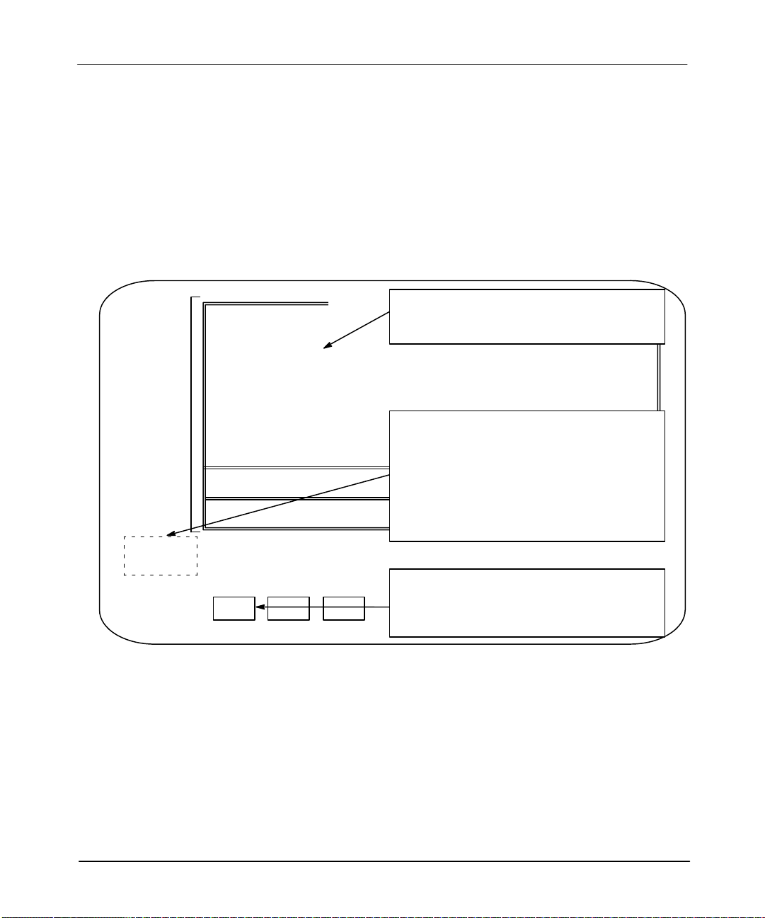
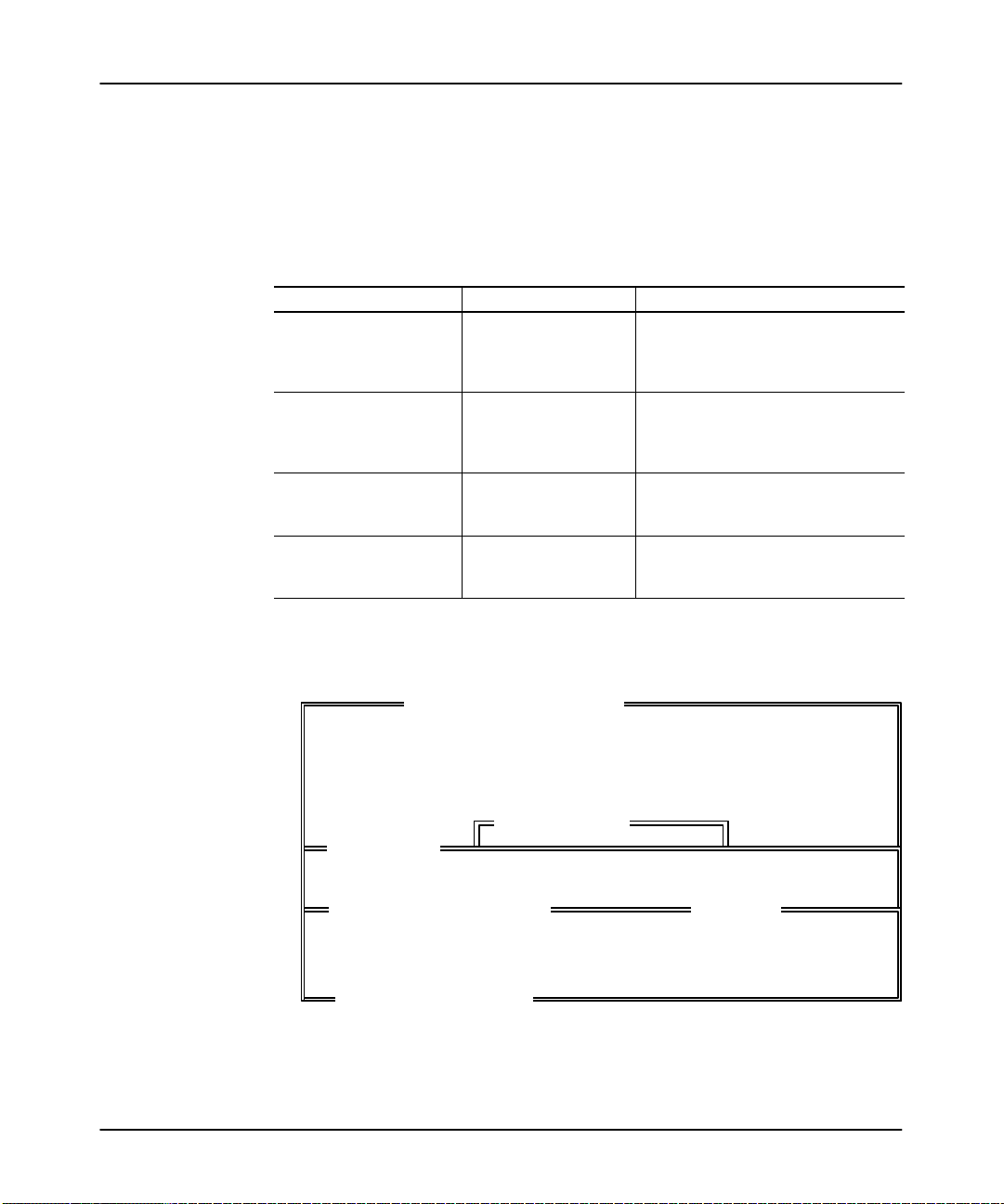
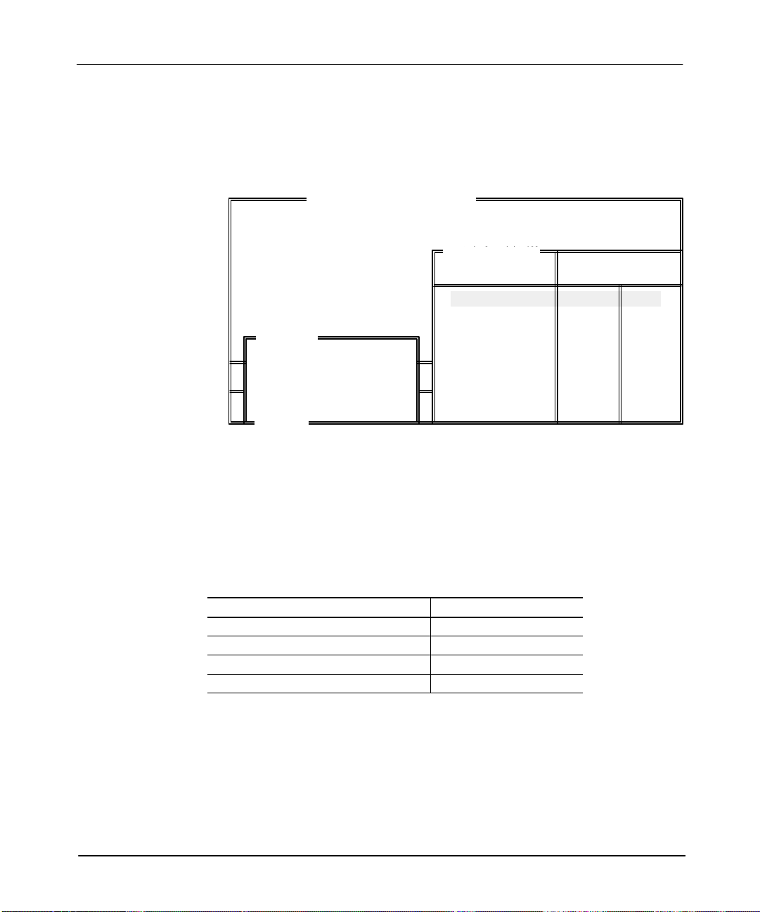
APSIE Display Format
The APSIE screen is divided into three areas:
•
display area
•
message, prompt, data entry and status lines
• APSIE menu functions
The screen below indicates what appears in these areas.
Display area
SLC-500 APS IMPORT/EXPORT UTILITY
Rockwell Software Incorporated, Copyright 1989–1995
This software
Display area: V
are performing.
9323 – PA2E
All Rights Reserved
Message line:
operation appear here.
arious windows overlay the display depending on the function you
Error codes/descriptions and information concerning terminal
Mon July 18, 1994
. . . Working . . .
F1 F2 F3
Data/Cmd entry:
Menu
Functions:
Message:
Prompt:
Status:
APSIE Menu Display
From the APSIE main menu there are three tasks that you can start. You can import
ASCII files, export APS files, or configure the utility
running APSIE, various windows are displayed depending on the function you are
accessing. The function keys also change as the windows change. See table 1.A.
1-4
Prompt line:
Indicates action you should take.
Data/Cmd entry line:
Status line:
Menu functions:
function keys F1 to F10. Pressing a main function key calls up subfunctions or
SELECT
OPTIONS
option windows.
F5 F7 F8 F9
Information entered from the keyboard appears on this line.
Status information concerning the program files appears on this line.
APSIE functions appear here. They are accessed by menu
EXPORT
ACH&DOC
EXPORT
ACH
EXPORT
DOC
. As you press keys while
Page 10

Table 1.A
Function Keys — APSIE Menu Display
Press this
main
function:
SYSTEM
CONFIGR
F6
IMPORT
F7
EXPORT
F8
DEFINE
DIR
COLOR
SELECT
F1 F3 F9
ARCHIVE
DIR
ASCII
DIR
F4 F6 F7
DEFINE
SELECT
DIR
SOURCE
F1 F3 F4
ARCHIVE
DIR
ASCII
DIR
F4 F6 F7
DEFINE
SELECT
DIR
SOURCE
F1 F3 F4
ANNOTAT
FILES
F1 F3 F4
ARCHIVE
DIR
ASCII
DIR
F4 F6 F7
SAVE
CONFIG
ENTER
DESTIN
ENTER
DESTIN
SORT
ORDER
CONFIG
DIR
CONFIG
DIR
CONFIG
DIR
These subfunctions are accessed:
SAVE
CONFIG
F9
SELECT
OPTIONS
SELECT
OPTIONS
KEYWORD
OPTION
IMPORT
SLC&TXT
IMPORT
F5 F7 F8
YES NO
F8 F10
IGN
SLC
ERRORS
ON
COLLISN
F3 F5 F6
SAVE
CONFIG
F9
EXPORT
ACH&DOC
F5 F7 F8
YES NO
F8 F10
SYMBOLSF5ADDRESS
SAVE
CONFIG
F9
SLC
DEFAULT
KEYWORD
EXPORT
ACH
COMMENT
F6 F7 F8
Introducing the
IMPORT
TXT
F9
YES NO
F8 F10
IGN TXT
ERRORS
EXPORT
DOC
F9
YES NO
F8 F10
INSTR
COMMENT
APS Import/Export Utility
[F8]
- YES and [F10] - NO
are only displayed when the
processor definition is in
error, or an overwrite
destination file message is
displayed.
SAVE
CONFIG
F7
F9
[F8]
- YES and [F10] - NO
are only displayed when an
overwrite destination file
message is displayed.
RUNG
COMMENT
TOGGLE
ENTRY
F1 F2 F3
SAVE
CONFIG
ALL
YES
SELECT
TYPES
F9
F10
ALL
NO
1-5
Page 11
APS Import/Export Utility User Manual
Preface
Starting the Utility
Select a task to perform from table 1.B.
Table 1.B
Selecting a Task from the Main Menu
If you want to: Press: Then:
configure the
import/export utility
import a file [F7] - IMPORT
export a file [F8] - EXPORT
exit the utility [F10] - EXIT SYSTEM
[F6] - SYSTEM CONFIGR
see chapter 2, Configuring the APS
Import/Export Utility.
see chapter 3, Importing ASCII
Documentation/Archive Files.
see chapter 4, Exporting APS
Documentation/Archive Files.
APSIE software is terminated, the screen
clears, and you are returned to DOS.
1-6
Page 12

Configuring the
APS Import/Export Utility
2
Configuring the APS Import/Export
Software
This
chapter shows you how to:
•
choose between color and monochrome screens. (Y
adaptor card and color monitor to use the color selection.)
• specify the user drives and directories
This chapter assumes that you have installed the APS/APSIE software and selected
the [F6] – SYSTEM CONFIGR function key from the main menu. If not, see
chapter 1, Introducing the APS Import/Export Utility.
ou must have a color
2-1
Page 13

APS Import/Export Utility User Manual
Preface
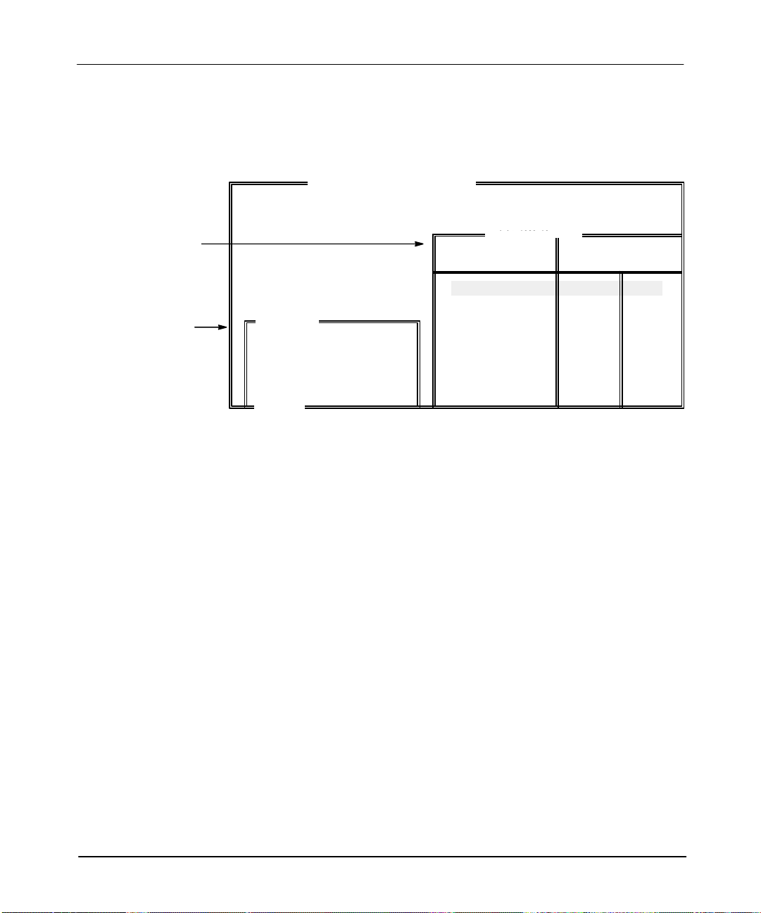
Configuring the System
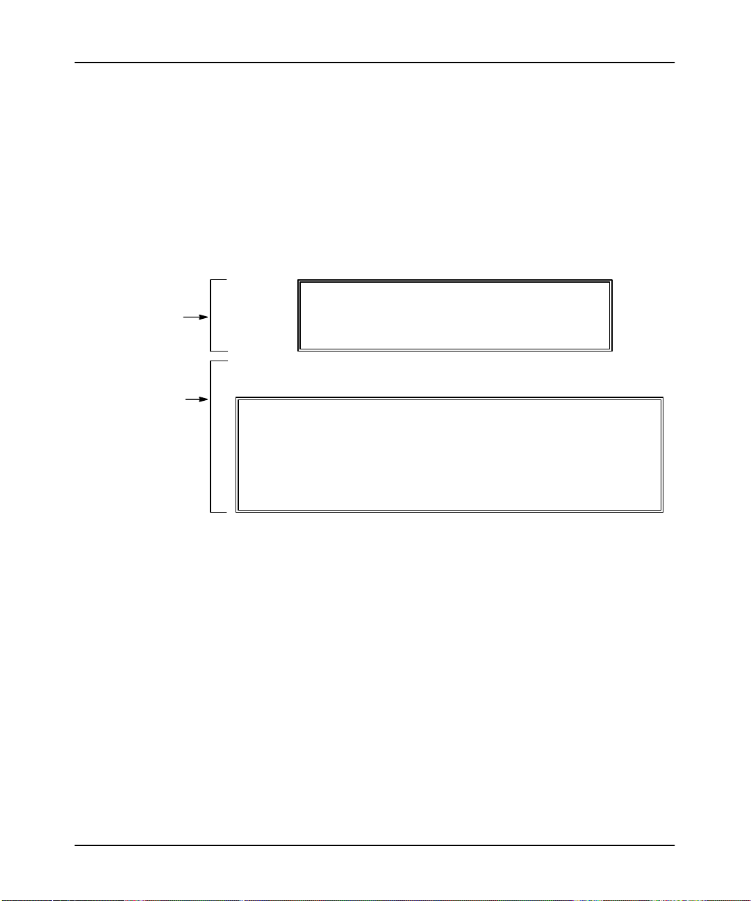
After selecting [F6] – SYSTEM CONFIGR, the import/export utility displays the
system configuration screen.
SLC–500 APS IMPORT/EXPORT UTILITY
Rockwell Software Incorporated, Copyright 1989–1995
This softwa
Press a function key
9323 – PA2E
SYSTEM CONFIGURATION
All Rights Reserved
F1 Define Directories
F3 Color Selection Monochrome
F9 Save Configuration
ESC exits/ALT–U aborts changes
From this menu you can do the following:
• choose color or monochrome screens
• define user directories
• save the configuration
Table 2.A explains what to do for either task.
2-2
Page 14
Configuring the
APS Import/Export Utility
Table 2.A
Specifying User Directories or Choosing between Color and
Monochrome Screens
If you want to: Press: Then:
specify the user directories
choose between color or
monochrome displays
save the configuration
permanently
➀
You must have a color adaptor card and color monitor to use the color selection.
➁
Indicates the user preference default.
[F1] - DEFINE DIR
➀
[F3] - COLOR SELECT
[F9] - SAVE CONFIG
see the following section, Specifying the
User Directories.
toggle between COLOR and
MONOCHROME
➁
SAVE CONFIG or
your choice.
APSIE saves the configuration to the
user preference file.
, then press [F9] -
[ESC] after making
2-3
Page 15
APS Import/Export Utility User Manual
Preface
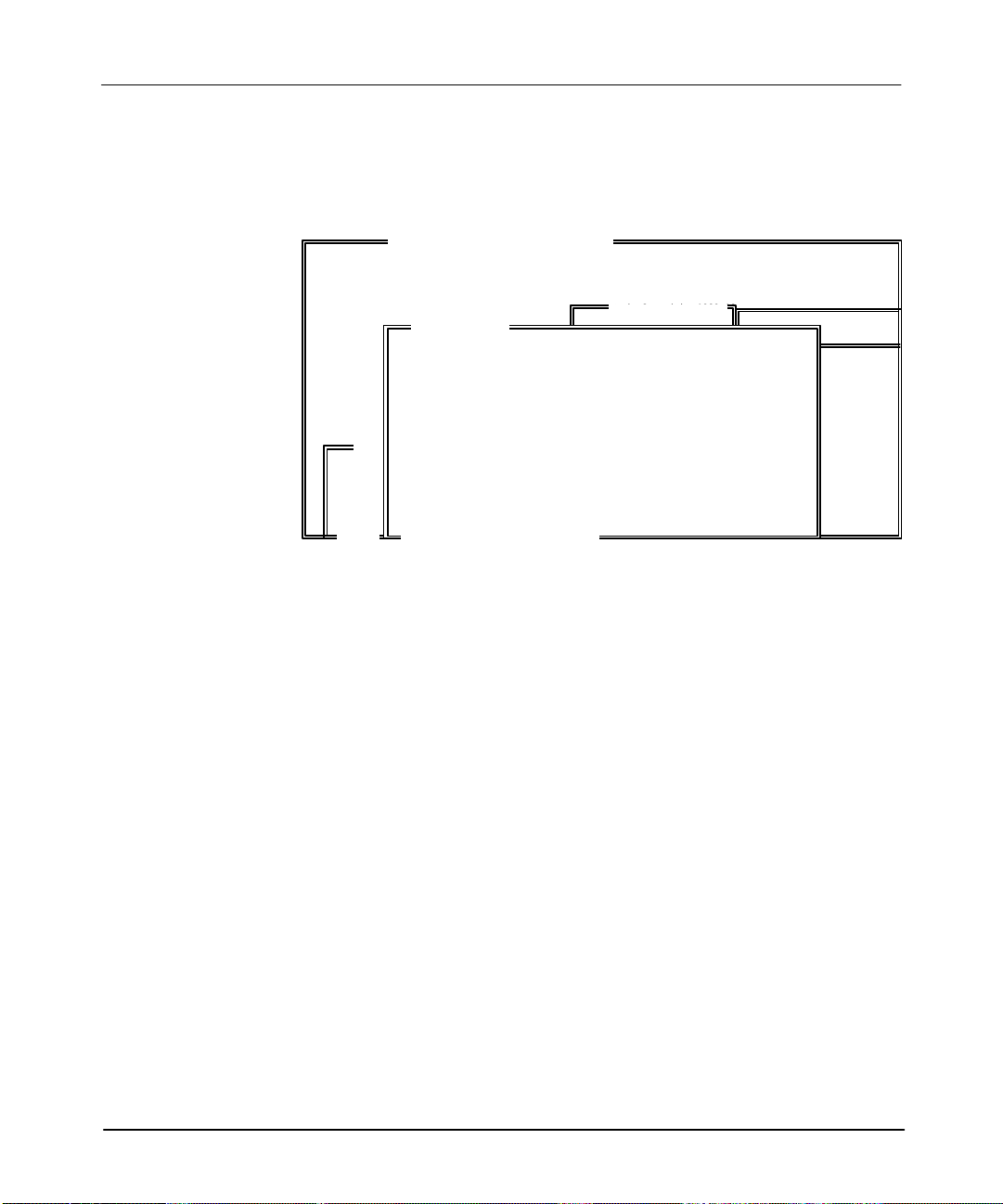
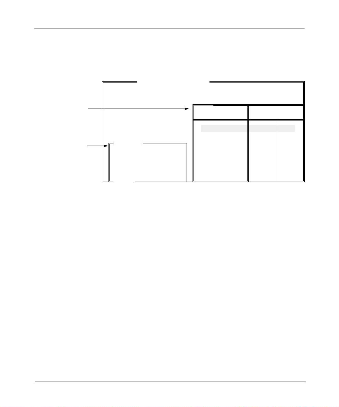
Specifying the User Directories
Below is the user directories screen. The directory paths shown are the default
directories when the import/export utility is first run. The maximum number of
characters in the pathname is 65. If there are more characters in the pathname than
can fit in the window
periods (...), for example:
“C:\THIS\IS\A\LONG\PATHNAME\FOR\THE\WINDOW...”
, the last 3 characters of the pathname are displayed as three
SLC–500 APS IMPORT/EXPORT UTILITY
User Directories
Window:
These are the
current directories
that the
import/export utility reads
files from and writes files to.
Rockwell Software Incorporated, Copyright 1989–1995
SYSTEM CONFIGURATION
USER DIRECTORIES
F4 APS Archive, Comments and Symbols: C:\IPDS\ARCH\SLC500
F6 ASCII Archive, Comments and Symbols: C:\IPDS\TEXT\SLC500
F7 User Configuration: C:\IPDS\ATTACH\SLC500
F9 Save Configuration
ESC exits/ALT–U aborts changes
Press a Function Key
F1 Define Directories
F3 Color Selection Monoc
hrome
F9 Save Configuration
ESC exits/ALT–U aborts changes
9323 – PA2E
All Rights Reserved
2-4
Page 16
Configuring the
APS Import/Export Utility
To enter a user directory
, follow these steps:
1. Select the type of directory that you want to specify from table 2.B.
Table 2.B
Entering the User Directories
If you want to: Press: Then:
specify the directory where
APS archive and
documentation files are
[F4] - ARCHIVE DIR the screen below is displayed.
stored
specify the directory where
ASCII archive and
documentation files are
[F6] - ASCII DIR the screen below is displayed.
stored
specify the directory where
the user preference file is
[F7] - CONFIG DIR the screen below is displayed.
stored
save the options displayed
on this screen to the user
preference file
[F9] - SAVE CONG
APSIE saves the configuration to the
user preference file.
The text in the window varies depending on the function key pressed. For example,
below is the “APS Archive, Comments and Symbols” window
SLC–500 APS IMPORT/EXPORT UTILITY
.
Rockwell Software Incorporated, Copyright 1989–1995
SYSTEM CONFIGURATION
USER DIRECTORIES
F4 APS Archive, Comments and Symbols: C:\IPDS\ARCH\SLC500
APS ARCHIVE, COMMENTS and SYMBOLS
\ipds\arch\slc500\this\is\a\valid\path
ESC exits/ALT–U aborts changes
F1 Define Directories
F3 Color Selection Monoc
hrome
F9 Save Configuration
ESC exits/ALT–U aborts changes
9323 – PA2E
All Rights Reserved
[ OVERWRITE ]
2-5
Page 17

APS Import/Export Utility User Manual
Preface
2. Enter the directory pathname. Press [INSERT] to toggle between overwrite
and insert modes.
Overwrite mode – writes over and destroys text that may already exist.
Insert mode – writes new text without destroying the already existing text.
3. Press either:
[ENTER] or [ESC] – to save the drive and directory pathname and return to
the previous display
OR
[ALT–U] – to discard any changes that were made and return to the previous
display.
.
After you press [ENTER], [ESC] or [ALT–U]
, the user directories screen is
displayed. If you want to enter another user directory, return to the start of this
section. If you want to save your configuration, press [F9].
2-6
Page 18

Importing
ASCII Documentation/Archive Files
3
Importing ASCII Documentation/
Archive Files
This
chapter describes how to:
• configure the import utility
• import ASCII files
• examine the results of the import
At this point we assume that you have installed the APS/APSIE software and
selected [F7] – IMPORT from the main menu. If not see chapter 1, Introducing the
APS Import/Export Utility.
3-1
Page 19
APS Import/Export Utility User Manual
Preface
Configuring the Import Utility
After selecting [F7] – IMPORT from the main menu, the import screen is displayed.
SLC–500 APS IMPORT/EXPORT UTILITY
DIR Window:
Contains the names
of all the ASCII
source files that exist
in the specified
directory.
Import Files
Window:
Contains the names
of the ASCII
source file and the
APS destination
file selected.
C:\IPDS\TEXT\SLC500
File Names
EXAMPLE1
EXAMPLE2
EXAMPLE3
EXAMPLE4
EXAMPLE5
SLC
Exists
➀
SLC
SLC
IMPORT FILES
SOURCE: EXAMPLE1
DESTIN: ABC
ESC exits
Press a Function Key or Enter File Name
➀
In
the DIR window
, notice the abbreviated words SLC" and TXT": SLC indicates that an ASCII archive file exists;
Rockwell Software Incorporated, Copyright 1989–19
This software is licensed to: ALL
9323 – PA2E
All Rights Reserved
NOT
NOW
TXT indicates that an ASCII program documentation file exists for a particular filename. (The absence of one or the
other means that it does not exist.)
Select an import task to perform from table 3.A.
TXT
➀
TXT
TXT
TXT
3-2
Page 20

Importing
ASCII Documentation/Archive Files
Table 3.A
Selecting an Import Task to Perform
If you want to: Press: Then:
define a directory [F1] - DEFINE DIR
use as the import SOURCE
file the name of the file that
the cursor is on
enter the name of the import
destination file
change the various options
that control how the import
process works
import ASCII archive and
documentation files
[F3] - SELECT
SOURCE
[F4] - ENTER DESTIN
[F5] - SELECT
OPTIONS
[F7] - IMPORT SLC &
TXT
import an ASCII archive file [F8] - IMPORT SLC see the section, Importing ASCII Files.
import an ASCII
documentation file
discard any changes that
were made
[F9] - IMPORT TXT see the section, Importing ASCII Files.
the [ESC] key
see chapter 2, Configuring the APS
Import/Export Utility.
APSIE places the filename on the
SOURCE line.
enter the destination file name
or with DESTIN blank, press
[ENTER]
to use the same file name as SOURCE.
see the next section, Selecting Options.
see the section, Importing ASCII Files.
APSIE discards any changes that were
made and returns the previous display.
3-3
Page 21
APS Import/Export Utility User Manual
Preface
Selecting Import Options
After selecting [F5] – SELECT OPTIONS from the main import menu, the
import/export utility displays the Import Options window.
SLC–500 APS IMPORT/EXPORT UTILITY
IMPORT
SOURCE
DESTIN:
ESC e
Press a Function Key
Rockwell Software Incorporated, Copyright 1989–19
IMPORT OPTIONS
ASCII ARCHIVE FILE OPTIONS
F3 Ignore SLC Archive Errors NO
ASCII PROGRAM DOCUMENTATION FILE OPTIONS
F5 On Collisions DISCARD
F6 Default Keyword SYMBOL
F7 Ignore TXT Documentation Errors YES
F9 Save Configuration
ESC exits/ALT–U aborts changes
All Rights Reserved
C:\IPDS\TEXT\SLC500
9323 – PA2E
File Names
Exists
TXT
TXT
TXT
TXT
This screen offers you options for configuring the import of both ASCII archive and
documentation files. The function keys for this screen, with the exception of [F9] –
SAVE CONFIG, toggle through all the possible values for a given option.
For example, the “Ignore TXT Documentation Errors” option: Function key [F7] –
IGN TXT ERRORS toggles between the values “yes” and “no”, which are the only
possible values for this option.
Note APSIE can import online edit INSERT, REPLACE, and DELETE rungs. You can
only cr
eate these rungs with an SLC 5/03 or SLC 5/04 pr
on the use of these rungs, see the Advanced Programming Softwar
ocessor
. For mor
e details
e User Manual.
3-4
Select import options from table 3.B.
Page 22
Importing
[F3]
[F3] - IGN SLC
choose the keyword that the
[F6]
[F6] - DEFAULT
documentation file without a
[F7]
[F7] - IGN TXT
Table 3.B
Selecting Import Options
If you want to: Toggle: Until the status is:
ignore any errors detected
during the archive import
process
abort the archive import
process when any errors
are detected
ignore any duplicate or
conflicting entries in the
imported ASCII
documentation file
overwrite any duplicate or
conflicting entries in the
imported ASCII
documentation file
choose the keyword that the
import utility will use for any
line in the ASCII
➂
keyword
ignore any errors detected
during the documentation
import process
abort the documentation
import process when any
errors are detected.
If you want to: Press: Then:
save the configuration
permanently
use this configuration for the
session only
discard any changes that
were made
➀
Indicates
➁
➂
the user preference default.
Y
ou can choose only one of the four keywords as the default keyword.
This only applies if you are not using keywords to group similar statements.
- IGN SLC
ERRORS
[F5] - ON COLLISION
- DEFAULT
KEYWORD
- IGN TXT
ERRORS
[F9] - SAVE CONFIG
[ENTER] or [ESC]
[ALT–U]
ASCII Documentation/Archive Files
YES
➀
NO
DISCARD
➀
OVERWRITE
SYMBOL
ADDR. COMMENTS
INSTR. COMMENTS
RUNG COMMENTS
➀➁
➁
➁
➁
YES
➀
NO
APSIE saves the configuration to the
user preference file.
APSIE accepts any changes that were
made. Once APSIE is terminated, the
changes are discarded.
APSIE discards any changes that were
made and returns the previous display.
3-5
Page 23
APS Import/Export Utility User Manual
Preface
Importing ASCII Files
To import an ASCII file, follow these steps:
1. Start on the main import screen shown below.
SLC–500 APS IMPORT/EXPORT UTILITY
Rockwell Software Incorporated, Copyright 1989–19
This software is licensed
IMPORT FILES
SOURCE: EXAMPLE1
Th
DESTIN: ABC
ESC exits
Press a Function Key or Enter File Name
to:
ALL
NOT
NOW
C:\IPDS\TEXT\SLC500
9323 – PA2E
All Rights Reserved
File Names
EXAMPLE1
EXAMPLE2
EXAMPLE3
EXAMPLE4
EXAMPLE5
2. See table 3.C to perform the import.
Table 3.C
Importing ASCII Files
If you want to: Then:
import ASCII archive & documentation files [F7] - IMPORT SLC & TXT
import an ASCII archive file only [F8] - IMPORT SLC
import an ASCII documentation file only [F9] - IMPORT TXT
return to the main menu display [ESC]
SLC
SLC
SLC
Exists
TXT
TXT
TXT
TXT
3-6
Page 24
Importing
ASCII Documentation/Archive Files
Note If
Display Area:
Import Status Area:
These areas provide
continually updated
status information
on the performance
of the import.
the pr
ocessor type is incorr
missing or incorr
• pr
ess
[F8] Yes
• pr
ess
[F10] No to allow the import to continue (An ar
ect in .SLC file. Configur
to r
ect you ar
econfigure I/O
e immediately pr
e I/O?, You can:
ompted: “Pr
chive file will not be
created).
o corr
ect the I/O configuration, refer to the Advanced Pr
T
ogramming Softwar
User Manual. (APSIE uses the same I/O configuration function as APS.)
Once the import process starts, the following screen is displayed.
Rockwell Software Incorporated
9323 Series Software
SLC–500 IMPORT/EXPORT SOFTWARE
Source: FILE1 Utility: Import Documentation
Destin: FILE1 Status: Importing Archive File
Phase: Line 5
BEGIN ASCII ARCHIVE IMPORT
ASCII ARCHIVE FILE OPTIONS:
IGNORE SLC ARCHIVE ERRORS: NO
PASS 1
ocessor type
e
• abort
The information in the bottom window of the import status area provides the same
information that is stored in a log file. When the import is complete, you have the
option of viewing the log file or returning to the previous screen.
Note You
the newly cr
editor.
the import by pr
cannot download the pr
eated APS archive file into APS and then save the file from the offline
essing
[Control – C]
ogram to a pr
ocessor immediately
. Y
ou must first load
3-7
Page 25

APS Import/Export Utility User Manual
Preface
Examining the Results of the Import
The log file provides the results of the import. It lists any errors that the utility
encountered during the import process. For each error, it identifies the type of error
and the location where the error was encountered in the ASCII file. “Illegal
Addresses” and “Illegal Comments” are two examples of errors that you may
encounter.
The default location for the log file is \IPDS\TEXT\SLC500. The log filename
consists of the APSIE archive path, which you defined while configuring the import
utility using [F6] ASCII DIR, the destination file name which you defined in
the import utility using [F4] ENTER DESTIN, and the file extension .LOG.
APSIE also allows you to verify that a new archive file was created. The default
location for the archive file is \IPDS\ARCH\SLC500. The archive filename consists
of the destination filename and the file extension .ACH.
3-8
Page 26

Exporting
APS Documentation/Archive Files
4
Exporting APS Documentation/
Archive Files
This
chapter shows you how to:
• configure the export utility
• export APS files
• examine the results of the export
At this point we assume that you have installed the APS/APSIE software and
selected [F8] – EXPORT from the main menu. If not, see chapter 1, Introducing the
APS Import/Export Utility.
4-1
Page 27
APS Import/Export Utility User Manual
Preface
Configuring the Export Utility
After selecting [F8] – EXPORT from the main menu, the import/export utility
displays the main export screen.
SLC–500 APS IMPORT/EXPORT UTILITY
DIR Window:
Contains the
names of all the
APS source files
that exist in the specified
directory.
Export Files
Window:
Contains the
names of the APS
source file and the
ASCII destination
file selected.
EXPORT FILES
SOURCE: EXAMPLE1
DESTIN: ABC
ESC exits
Press a Function Key or Enter File Name
➀
In
the DIR window
, notice the abbreviated words ACH" and DOC": ACH indicates that an APS archive file exists;
Rockwell Software, Inc.
This software is licensed
to:
ALL
NOT
NOW
9323 – PA
All Rights
EXAMPLE1
EXAMPLE2
EXAMPLE3
EXAMPLE4
EXAMPLE5
C:\IPDS\ARCH\SLC500
File Names
ACH
Exists
➀
ACH
ACH
DOC indicates that an APS program documentation file exists for a particular filename. (The absence of one or the
other means that it does not exist.)
Select an export task to perform from table 4.A.
DOC
➀
DOC
DOC
DOC
4-2
Page 28
Exporting
APS Documentation/Archive Files
Table 4.A
Selecting an Export Task to Perform
If you want to: Press: Then:
define a directory
use as the export SOURCE
file the name of the file that
the cursor is on
[F1] - DEFINE DIR
[F3] - SELECT
SOURCE
enter the name of the export
destination file
change the various options
that control how the export
process works
export APS archive and
documentation files
[F4] - ENTER DESTIN
[F5] - SELECT
OPTIONS
[F7] - EXPORT ACH &
DOC
export an APS archive file [F8] - EXPORT ACH see the section, Exporting APS Files.
export an APS
documentation file
[F9] - EXPORT DOC see the section, Exporting APS Files.
discard any changes made
during the session
[ESC]
see Chapter 2, Configuring the User
Directory.
APSIE places the filename on the
SOURCE line.
enter the destination file name
or with DESTIN blank, press
[ENTER]
to use the same file name as SOURCE.
see the next section, Selecting Options.
see the section, Exporting APS Files.
any changes made during the session
are discarded and the previous display is
returned.
4-3
Page 29

APS Import/Export Utility User Manual
Preface
Selecting Export Options
After selecting [F5] – SELECT OPTIONS from the main export menu, the
import/export utility displays the Export Options window.
SLC–500 APS IMPORT/EXPORT UTILITY
EXPORT OPTIONS
ARCHIVE FILE OPTIONS
F1 Annotate ASCII Archive File YES
PROGRAM DOCUMENTATION FILE OPTIONS
F3 Sort Order ADDRESS STRING
F4 Keyword Option ALL
F5 Symbols EXPORT
F6 Address Comments DO NOT EXPORT
F7 Instruction Comments EXPORT
F8 Rung Comments DO NOT EXPORT
F10 Select Address Types O,I,S,B,T,C,R,N,F,M0,M1,ST,A,Labels
F9 Save Configuration
ESC exits/ALT–U aborts changes
Press a Function Key
Rockwell Software, Inc.
Copyright 1980
This screen offers you options for configuring the export of both APS archive and
documentation files. The function keys for this particular screen, with the exception
of [F9] – SAVE CONFIG, toggle through all the possible values for a given option.
Take for example the ANNOTAT FILES option: function key [F1] – ANNOTAT
FILES toggles between the values “yes” and “no”, which are the only possible
values for this option. Select an export option from table 4.B.
Note APSIE can export online edit INSERT, REPLACE, and DELETE rungs. You can
only cr
eate these rungs with an SLC 5/03 or an SLC 5/04 pr
details on the use of these rungs, see the Advanced Programming Softwar
ocessor
. For mor
e User
e
Manual.
4-4
Page 30

[F1] ANNOTAT FILE
[F3]-SORT ORDER
[]
Exporting
APS Documentation/Archive Files
Table 4.B
Selecting Export Options
If you want to: Toggle: Until the status is:
export the ASCII archive file
with comments explaining
the various sections, like
processor type and data
tables
[F1] - ANNOTAT FILE
export the ASCII archive file
without comments
explaining the various
sections.
sort by ascending order of
the address value, as in:
N7:0, N10:2, N10:10
sort by ascending order of
the address string as in:
N10:10, N10:2, N7:0
sort into groups the
-
comments in the ASCII
documentation file in this
order: symbols, address,
instruction and then rung
comments
place all the keywords for
symbols, rung, instruction,
and address comments at
the beginning of every
statement in the ASCII
documentation file
place keywords at the
beginning of groups with
similar statements
➂
[F4] - KEYWORD
OPTIONS
remove keywords from the
ASCII documentation file
export symbols EXPORT
remove symbols from the
[F5] - SYMBOLS
ASCII documentation file
export address comments EXPORT
remove address comments
from the ASCII
[F6] - ADDRESS
COMMENTS
documentation file.
export instruction comments EXPORT
remove instruction
comments from the ASCII
[F7] - INSTR
COMMENTS
documentation file
➀
YES
NO
ADDRESS VALUE
ADDRESS STRING
KEYWORD
➀➁
ALL
DEFAULT
NONE
➁
➁
➀
DO NOT EXPORT
➀
DO NOT EXPORT
➀
DO NOT EXPORT
➀
4-5
Page 31

APS Import/Export Utility User Manual
Preface
If you want to: Until the status is:Toggle:
export rung comments
remove rung comments
from the ASCII
documentation file
save the configuration
permanently
use this configuration for
this session only
discard any changes that
were made
➀
Indicates
➁
➂
the user preference default.
Y
ou must specify Sort by Keyword" on this screen, otherwise the default keywords do not appear in the exported file.
Y
ou can choose only one keyword option as the keyword options default.
[F8] - RUNG
COMMENTS
[F8] - RUNG
COMMENTS
[F9] - SAVE CONFIG
[ENTER] or [ESC]
[ALT–U]
EXPORT
➀
DO NOT EXPORT
APSIE saves the configuration to the
user preference file.
APSIE accepts any changes that were
made. Once APSIE is terminated, the
changes are discarded.
APSIE discards any changes that were
made and returns the previous display.
4-6
Page 32

Selecting Export Address Types
After selecting [F10] – SELECT TYPES from the export options screen, APSIE
displays the following window, labeled “Select Export Address Types.”
SLC–500 APS IMPORT/EXPORT UTILITY
EXPORT OPTIONS
SELECT EXPORT ADDRESS TYPES
Press a Function Key
Outputs YES
Inputs NO
Status YES
Bit/Binary YES
Timer NO
Counter YES
Control NO
Integer YES
Float NO
M0 NO
M1 YES
String NO
ASCII NO
Labels YES
ESC exits/ALT–U aborts changes
Exporting
APS Documentation/Archive Files
Labels
From
you want to export.
Use the up– and down–arrow cursor keys to move through the address types
displayed in the window, highlighting those types you wish to change.
Tables 4.C and 4.D provide you with two options for configuring the address types:
table 4.C explains how you can change the status of each address type one at a time;
table 4.D explains how you can configure the export utility so that all or none of the
address types are exported.
Note After
permanently by pr
(Pr
this screen you select which address types in the ASCII documentation file
you have configur
ess
[ENTER]
ed the addr
essing [F9] – SA
or
[ESC]
to save the configuration for this session only
ess types, you can save the configuration
VE CONFIG fr
om the Export Options window
.)
.
4-7
Page 33

APS Import/Export Utility User Manual
[F1]
[F1] - TOGGLE
Preface
Table 4.C
Selecting the Export Address Types Individually
If you want to: Toggle: Until the status is:
export all of the program
documentation for
addresses of the type that
you have highlighted.
export none of the program
documentation for
addresses of the type that
you have highlighted.
If you want to: Press: Then:
use this configuration for the
session only
discard any changes that
were made
Table 4.D
Selecting All or None of the Export Address Types
- TOGGLE
ENTRY
[ENTER] or [ESC]
[ALT–U]
YES
NO
APSIE accepts any changes that were
made. Once APSIE is terminated, the
changes are discarded.
APSIE discards any changes that were
made and returns the previous display.
4-8
If you want to: Press:
export all of the program
documentation for all
address types.
export none of the program
documentation for any
address type.
use this configuration for the
session only and return to
the previous display
discard any changes that
were made and return to the
previous display
[F2] - ALL YES
[F3] - ALL NO
[ENTER] or [ESC]
[ALT–U]
Page 34

Exporting APS Files
To export an APS file, follow these steps:
1. Start from the main export display shown below.
SLC–500 APS IMPORT/EXPORT UTILITY
Exporting
APS Documentation/Archive Files
Rockwell Software, Inc.
This software is licensed
EXPORT FILES
SOURCE: EXAMPLE1
DESTIN: ABC
ESC exits
Press a Function Key or Enter File Name
to:
ALL
NOT
NOW
9323 – PA
All Rights
2. See the table below to perform the export.
If you want to: Press:
export APS archive &
documentation files
export an APS archive file
only
export an APS
documentation file only
return to the main menu [ESC]
[F7] - EXPORT ACH &
DOC
[F8] - EXPORT ACH
[F9] - EXPORT DOC
File Names
EXAMPLE1
EXAMPLE2
EXAMPLE3
EXAMPLE4
EXAMPLE5
C:\IPDS\TEXT\SLC500
ACH
ACH
ACH
Exists
DOC
DOC
DOC
DOC
4-9
Page 35

APS Import/Export Utility User Manual
Preface
After
the export process begins the screen below is displayed.
Display Area:
Source FILE1 Utility: Export Archive File
Destin: FILE1 Status: Exporting Archive File
Phase: Line 5
Export Status Areas:
These areas provide
continually updated
status information on the
performance of
the export.
BEGIN APS ARCHIVE EXPORT
ARCHIVE EXPORT OPTIONS
The information in the bottom window of the export status area provides the same
information that is stored in the log file. When the export is complete, you have the
option of either viewing the log file or returning to the previous screen.
Rockwell Software Incorporated
9323 Series Software
SLC–500 IMPORT/EXPORT SOFTWARE
ANNOTATE ASCII ARCHIVE FILE: YES
Examining the Results of the Export
The log file provides the results of the export. It lists any errors that the utility
encountered during the export process. For each error, it identifies the type of error
and the location where the error was encountered in the ASCII file. “Illegal
Addresses” and “Illegal Comments” are two examples of errors that you may
encounter.
The default location for the log file is \IPDS\TEXT\SLC500. The log filename
consists of the APSIE archive path, which you defined while configuring the export
utility using [F6] ASCII DIR, the destination file name which you defined in
the export utility using [F4] ENTER DESTIN, and the file extension .LOG.
APSIE also allows you to verify that a new text file was created. The text filename
consists of the destination filename and the file extension .TXT.
4-10
Page 36

Creating an
ASCII
Archive File
5
Creating an ASCII Archive File
This chapter shows you how to create your own SLC 500 program in ASCII archive
file format. You can use these programs with the import utility. This chapter
consists of the following sections:
•
explaining keywords, operands, and comments
• specifying ASCII archive files
• protecting archive files
• examining ASCII archive files
So that you may better understand and see the relationship between APS and ASCII
programming languages, example APS ladder programs are included with the
example ASCII programs.
5-1
Page 37

APS Import/Export Utility User Manual
Preface
Explaining Keywords, Operands, and Comments
Each section of the ASCII archive file usually consists of keywords, operands, and
comments.
Keywords
Keywords include symbols and ladder instruction mnemonics. T
able 5.A explains
the location of each keyword in the ASCII archive file.
Table 5.A
Defining Keywords
This Keyword Precedes
START the start of an ASCII file.
RACK the definition of an expansion chassis. (does not apply to MicroLogix
SLOT the definition of an I/O module. (does not apply to MicroLogix 1000
DATA the definition of a data table file.
PROJECT the project name and ladder filenames.
LADDER the definition of a ladder file.
FORCE the definition of a force table.
CHAN_CONFIG the definition of a channel configuration file. (SLC 5/03 and SLC 5/04
INPUT_FILTERS the definition of an input filter file. (MicroLogix 1000 controllers only)
MULTIPOINT the definition of an I/O list. (SLC 5/03 OS302, SLC 5/04 OS401, and
1000 controllers)
controllers)
These keywords are used in conjunction with SLOT
(SLC 5/02, SLC 5/03, and SLC 5/04 processors only)
D SCAN_IN Number of scanned inputs.
D SCAN_OUT Number of scanned outputs.
D M1_SIZE Number of M1 data file words.
D M0_SIZE Number of M0 data file words.
D ISR Interrupt service routine file number.
D G_FILE Data for G-file.
processors only)
MicroLogix 1000 controllers only)
5-2
The SLC 5/03 and SLC 5/04 processors have three keywords that indicate that a file
is protected. See table 5.B.
Page 38

Creating an
Table 5.B
Defining Keywords for SLC 5/03 and SLC 5/04 Processors
This Keyword Indicates
PROTECT_DATA the type of DATA file protection applied to the specified file(s). The
following keywords are used in conjunction with PROTECT_DATA:
ASCII
Archive File
Operands
D CONSTANT Data file cannot be changed by the user or user
D STATIC Data file can only be changed by the user
D MEM_MOD Protects individual data files from changes
PROTECT_LAD the LADDER file(s) specified are protected.
PROTECT_FORCE that all FORCE file(s) are protected.
Operands are either
logical addr
esses or
program during program operation.
program during program operation.
during memory module transfers if the programs
match and are valid.
immediate values
. You can enter the
logical addresses in any valid format. The import utility generates the complete
address format. You may enter the immediate values in decimal, hex, octal, or
binary formats. See table 5.C.
Table 5.C
Defining Immediate Values
Format: Description: Example:
decimal
hex
octal
binary
floating point
a number with an optional plus or minus sign and
decimal digits.
a number that starts with a zero, followed by an X", then
any four characters from 0-9 or A-F.
a number that starts with a zero, followed by an O",
then any six digits from 0 to 7.
a number that starts with a zero, followed by a B", then
up to 16 zeros or ones.
a number with an optional plus or minus sign that falls in
the range of 3.402823x10
38
to 1.1754944x10
-38
or 0.0
-32768
OXFA90
0O370010
0B010110
-32768.00
5-3
Page 39

APS Import/Export Utility User Manual
Preface
Comments
You can add comments anywhere in the ASCII archive file when you create it.
To add a single line comment, place the comment after an exclamation mark (!). In
this case, the import utility ignores all text from the exclamation mark to the end of
the line.
You may also enter comments in the ASCII archive file by inserting the comment
between two percent signs. (Tabs, carriage returns or spaces before and after the
percent signs are optional.) For example: % This is a comment %. You may
include one or more carriage returns in a comment of this type.
Enter comments on a single line or several lines by themselves, or directly following
a complete ASCII command. If the import utility encounters a comment character
(% or !) between two quotation marks (“”), it considers the comment character as
part of the quoted string.
The following example shows you how comments may look in your import file.
Notice that the comments used to document ASCII files only describe those files.
The import utility does not store these comments in the database.
5-4
!This is an example of a single–line comment.
Project 1747–L511 % 1747–L511 IK Modular CPU %
LADDER 2
SOR !Rung 0 of File 2
XIC B3/0 OTL B3/1 EOR
SOR XIC B3/1 TON T4:0 0.01 1000 0 EOR % Timer 0 %
Page 40

Specifying ASCII Archive Files
When specifying an ASCII archive file, be aware of the following guidelines:
• To create the file, use a text editor that produces only printable ASCII
characters, with no control or hidden characters.
•
Do not use graphics characters.
The ASCII archive file is made up of six sections for MicroLogix 1000 controllers,
six sections for SLC 5/01 and SLC 5/02 processors, and seven sections for SLC 5/03
and SLC 5/04 processors. These sections are shown in table 5.D.
Creating an
ASCII
Archive File
Of these sections, you must arrange three of them, the program header
configuration, and module configuration (bold in table 5.D) in the order shown in
table 5.D. In general, you can enter the remaining sections in any order, beginning
with the data table section.
Note The
important if your program files contain instructions that use data table files to stor
control information. (For example, the MSG instruction uses a data table file to
stor
such cases, see the table below:
, chassis
or
der in which you enter the pr
ogram files section and the data table section is
e information such as the node number, message length, and file number
If you enter the after you enter the
data table section program files section
program files section data table section
be careful not to overwrite
the existing
control information with new
data table information.
data table values with
instruction control
information.
e
.) For
5-5
Page 41

APS Import/Export Utility User Manual
Preface
Table 5.D
ASCII Archive File
Program
Chassis Configuration
Module Configuration
Header
(does not apply to MicroLogix 1000 controllers)
(does not apply to MicroLogix 1000 controllers)
Project Name
Program Files
File 2
:
File n
Data T
able
Channel Configuration Data List (SLC 5/03 and SLC 5/04 processore only)
Adjustable Input Filters (MicroLogix 1000 controllers only)
Multi-Point I/O List (SLC 5/03 OS302, SLC 5/04 OS401 processors, and
MicroLogix 1000 controllers only)
5-6
Page 42

Specifying the Program Header
Creating an
ASCII
Archive File
The program header defines the target processor for the import utility. Y
ou must
provide information for this section of the archive file. (You could leave any of the
other six sections empty
.)
The program header format for fixed and modular controllers consists of the
keyword “START” and the controller catalog number. Do not enter the catalog
number with tabs or spaces. For “other” fixed controllers the program header
format consists of the keyword “START”, “OTHER–1K” and the processor ID.
See table 5.E.
Table 5.E
Program Header Formats and Examples
Program Header Format: Example Program Header:
START Controller_catalog_number START 1747-L20A
START Other-1K Processor_ID START OTHER-1K 1920
The available controllers include 20, 30, and 40 I/O fixed controllers, as well as 3
different modular processors. Input, output and line power information in the tables
is for reference only
. See tables 5.F
If you use a fixed processor not specified in tables 5.F
, G, H, I, and J.
, G, or H, you must use the
processor name “OTHER–1K” (undefined fixed controller with 1K of memory).
The processor ID refers to the ID code specified in the user manual for your
processor.
5-7
Page 43

APS Import/Export Utility User Manual
Preface
Table 5.F
20 I/O Fixed Controller
Controller
Catalog Number:
1747-L20A 12-120V ac 8-Relay 120/240V ac
1747-L20B 12-120V ac 8-Triac 120/240V ac
1747-L20C 12-dc Sink 8-Relay 120/240V ac
1747-L20D 12-dc Sink 8-Triac 120/240V ac
1747-L20E 12-dc Sink 8-Transistor 120/240V ac
1747-L20F 12-dc Sink 8-Relay 24V dc
1747-L20G 12-dc Sink 8-Transistor 24V dc
1747-L20L 12-dc Source 8-Transistor 24V dc
1747-L20N 12-dc Source 8-Transistor 24V dc
1747-L20P 12-240V ac 8-Triac 120/240V ac
1747-L20R 12-240V ac 8-Relay 120/240V ac
Inputs: Outputs: Line Power:
Table 5.G
30 I/O Fixed Controllers
Controller
Catalog Number:
1747-L30A 18-120V ac 12-Relay 120/240V ac
1747-L30B 18-120V ac 12-Triac 120/240V ac
1747-L30C 18-dc Sink 12-Relay 120/240V ac
1747-L30D 18-dc Sink 12-Triac 120/240V ac
1747-L30L 18-dc Source 12-Transistor 120/240V ac
1747-L30P 18-240V ac 12-Triac 120/240V ac
Inputs: Outputs: Line Power:
5-8
Page 44

Table 5.H
40 I/O Fixed Controllers
Creating an
ASCII
Archive File
Controller
Catalog Number:
1747-L40A 24-120V ac 16-Relay 120/240V ac
1747-L40B 24-120V ac 16-Triac 120/240V ac
1747-L40C 24-dc Sink 16-Relay 120/240V ac
1747-L40E 24-dc Sink 16-Transistor 120/240V ac
1747-L40F 24-dc Sink 16-Relay 24V dc
1747-L40L 24-dc Source 16-Transistor 120/240V ac
1747-L40P 24-240V ac 16-Triac 120/240V ac
Inputs: Outputs: Line Power:
Table 5.I
Modular Processors
Controller
Catalog Number:
1747-L511 SLC 5/01 1K User Memory
1747-L514 SLC 5/01 4K User Memory
1747-L524 SLC 5/02 4K User Memory
1747-L532 SLC 5/03 OS300 12K User Memory
1747-L532 SLC 5/03 OS301 12K User Memory
1747-L532 SLC 5/03 OS302 12K User Memory
1747-L541 SLC 5/04 OS401 12K User Memory
1747-L542 SLC 5/04 OS400 20K User Memory
1747-L542 SLC 5/04 OS401 28K User Memory
1747-L543 SLC5/04 OS401 60K User Memory
Type:
5-9
Page 45

APS Import/Export Utility User Manual
Preface
Table 5.J
MicroLogix 1000 Controllers
Controller
Catalog Number:
1761-L16AWA 10 pt. ac 6-Relay 120/240V ac
1761-L32AWA 20 pt. ac 12-Relay 120/240V ac
1761-L16BWA 10 pt. ac 6-Relay 120/240V ac
1761-L32BWA 20 pt. ac 12-Relay 120/240V ac
1761-L16BWB 10 pt. dc 6-Relay 120/240V ac
1761-L32BWB 20 pt. dc 12-Relay 120/240V ac
1761-L16BBB 10 pt. dc
1761-L32BBB 20 pt. dc
1761-L32AAA 20 pt. ac
Inputs: Outputs: Line Power:
4-FET and
2-Relay
10-FET and
2-Relay
10-Triac and
2-Relay
120/240V ac
120/240V ac
120/240V ac
5-10
Page 46

Creating an
ASCII
Archive File
Configuring the Chassis (Does Not Apply to MicroLogix 1000 Controllers)
The
chassis configuration format consists of the keyword “RACK”, the
number
and
have. For example:
RACK
Keyword Chassis Number Catalog Number
Specifying the Chassis Number
chassis number is the location of the expansion chassis in the I/O configuration.
The
An SLC 500 modular processor can use up to three chassis. The chassis containing
the processor is always chassis number 1. If you have more than one chassis,
number the chassis that follow number 2 and number 3. The chassis numbers must
be specified in order; that is, specify chassis 1 before specifying chassis 2. (3 is the
largest valid chassis number for modular style hardware.)
catalog number
1 1746–A4
.
Use this format for each expansion chassis that you
chassis
Chassis Number 1
SLC 500 Processor
SLC 500 Modular Controller
Chassis Number 2 Chassis Number 3
The SLC 500 fixed controller has only one chassis. Therefore, always enter 1 for
the chassis number when using a fixed processor with a 2–slot (1746–A2) expansion
chassis.
5-11
Page 47

APS Import/Export Utility User Manual
Preface
SLC 500 Fixed Controller
SLC 500 Processor 1746-A2
Specifying the Chassis Catalog Number
chassis catalog number defines the type of expansion chassis. When you enter
The
the catalog number
, do not use tabs or spaces between the numbers and letters.
If you enter an invalid catalog or chassis number, the import utility ignores the
chassis configuration section of the ASCII archive file and displays an error
message, which is written to the log file. Table 5.K lists the catalog numbers for the
available chassis. (The information concerning chassis description and type of
hardware style required is provided for reference only.)
Chassis Number 1
5-12
Table 5.K
Available Expansion Chassis
Catalog Number : Chassis Description:
1746-A2 2-slot Backplane Fixed
1746-A4 4-slot Backplane Modular
1746-A7 7-slot Backplane Modular
1746-A10 10-slot Backplane Modular
1746-A13 13-slot Backplane Modular
Type of Hardware
Style Required
(Modular/Fixed):
Page 48

Creating an
g
ASCII
Archive File
Configuring the I/O Slots (Does Not Apply to MicroLogix 1000 Controllers)
There are three formats that you can use to define the I/O slot configuration. The
format that you use depends on your module. See table 5.L.
Table 5.L
Determining which I/O Slot Format to Use
Use these
optional
If your module:
is listed in Table 5.M
is not included in Table 5.M
and the module ID number is
not 63xx, 95xx, 127xx, 159xx,
199xx, 223xx, or 255xx
is not included in Table 5.M
and the module ID is 63xx,
95xx, 127xx, 159xx, 199xx,
223xx, or 255xx
Use the following I/O Slot Format
(Core Elements):
(Format 1)
SLOT Slot_number Catalog_number
(Formal 2)
SLOT Slot_number Module_ID
(Format 3)
SLOT Slot_number
Extended_module_ID Max_input
Max_output
arguments with
the core elements
for Modular
Controllers only:
SCAN_IN x
SCAN_OUT x
M0_SIZE x
M1_SIZE x
ISR x
G FILE g_file_size
__
g_file_data . . .
(See Table 5.N for
greater detail on
the optional
arguments.)
5-13
Page 49

APS Import/Export Utility User Manual
Preface
Table 5.M
Available Modules for SLC 500
Description of Available Modules: Catalog Number:
4-input 100/120V ac 1746-IA4
8-input 100/120V ac 1746-IA8
16-input 100/120V ac 1746-IA16
4-input 200/240V ac 1746-IM4
8-input 200/240V ac 1746-IM8
16-input 200/240V ac 1746-IM16
8-output (TRIAC) 100/240V ac 1746-OA8
16-output (TRIAC) 100/240V ac 1746-OA16
8-input (SINK) 24V dc 1746-IB8
16-input (SINK) 24V dc 1746-IB16
32-Input (SINK) 24V dc 1746-IB32
16-input [TTL](SOURCE) 5V dc 1746-IG16
8-input (SOURCE) 24V dc 1746-IV8
16-input (SOURCE) 24V dc 1746-IV16
32-Input (SOURCE) 24V dc 1746-IV32
8-output [TRANS](SOURCE) 10/50V dc 1746-OB8
16-output [TRANS](SOURCE) 10/50V dc 1746-OB16
32-Output [TRANS](SOURCE) 10/50V dc 1746-OB32
8-output [TRANS](SINK) 10/50V dc 1746-OV8
16-output [TRANS](SINK) 10/50V dc 1746-OV16
32-Output [TRANS](SINK) 10/50V dc 1746-OV32
16-output [TTL](SINK) 5V dc 1746-OG16
4-output [RLY] 240V ac 1746-OW4
8-output [RLY] 240V ac 1746-OW8
16-output [RLY] 240V ac 1746-OW16
2-input 100/120V ac 2-Output [RLY] 1746-IO4
4-input 100/120V ac 4-Output [RLY] 1746-IO8
6-input 100/120V ac 4 6-Output [RLY] 1746-IO12
Node Adaptor Module (1/4 Chassis) 1747-DCM-1/4
Node Adaptor Module (1/2 Chassis) 1747-DCM-1/2
Node Adaptor Module (3/4 Chassis) 1747-DCM-3/4
Node Adaptor Module (Full Chassis) 1747-DCM-FULL
4 Channel Analog Input 1746-NI4
Analog Combination 2 In & 2 Current Out 1746-NIO4I
➀
Table
5.M continues on to the next page.
➀
5-14
Page 50

Creating an
Table 5.M
Available Modules for SLC 500 (continued)
Description of Available Modules: Catalog Number:
Fast Analog Combination 2 In & 2 Current Out 1746-FIO4I
Analog Combination 2 In & 2 Voltage Out 1746-NIO4V
Fast Analog Combination 2 In & 2 Voltage Out 1746-FIO4V
4 Channel Analog Current Output 1746-NO4I
4 Channel Analog Voltage Output 1746-NO4V
Single Axis Motion Controller 1747-HS
Remote I/O Scanner 1747-SN
Distributed I/O Scanner (7 blocks) 1747-DSN-7BLK
Distributed I/O Scanner (30 blocks) 1747-DSN-30BLK
High Speed Counter/Encoder Module 1746-HSCE
BASIC Module (SLC 5/01) 1746-BAS-5/01
BASIC Module (SLC 5/02) 1746-BAS-5/02
16-input 24V ac/dc 1746-IN16
8-Output Isolated Relay V ac/dc 1746-OX8
Any 8-pt Discrete Input Module 1746-I*8
Any 16-pt Discrete Input Module 1746-I*16
Any 32-pt Discrete Input Module 1746-I*32
Any 8-pt Discrete Output Module 1746-O*8
Any 16-pt Discrete Output Module 1746-O*16
Any 32-pt Discrete Output Module 1746-O*32
16-Input [FAST](SINK) 24V dc 1746-ITB16
High Current 120/240V ac Output Card 1746-OAP12
16-Input [FAST](SOURCE) 24V dc 1746-ITV16
4 Channel RTD/Resistance Module 1746-NR4
4 Channel Thermocouple Input Module 1746-NT4
16-Output [TRANS 1 AMP](SOURCE) 24V dc 1746-OBP16
16-Output [TRANS 1 AMP](SINK) 24V dc 1746-OVP16
Stepper Controller Module 1746-HSTP1
Device Net Scaner Module 1747-SDN
DH-485/RS-232C Interface Module (Series A) 1747-KEA
DH-485/RS-232C Interface Module (Series B) 1747-KEB
ASCII
Archive File
Table 5.N lists the optional arguments for 1746–L524, –L532, –L541, and –L542
modular controllers only.
5-15
Page 51

APS Import/Export Utility User Manual
Preface
Table 5.N
Optional Arguments
(For 1746–L524, –L532, –541, and –L542 modular controllers only)
Optional
Arguments:
SCAN_IN (0 - 32)
SCAN_OUT (0 - 32)
M0_SIZE
M1_SIZE
ISR (0, 3 - 255)
G_FILE (0 - 255)
Use these integers
with the optional
argument:
➀
➀
(0 - 32768)
(0 - 32768)
➁
➂
These integers specify:
how many words of input the I/O scan updates.
how many words of output the I/O scan updates.
the size, in words, of the M0 file. The sum of Input,
Output, G file, M0 and M1 file sizes must not
exceed 32768 words.
the size, in words, of the M1 file. The sum of Input,
Output, G file, M0 and M1 file sizes must not
exceed 32768 words.
a subroutine file number.
the number of words that the import utility allocates
for the G file. (See Table 5.O for example G-file
arguments.)
➀
Make
sure that the integer specified is less than or equal to the number of output words allowed for the module
specified by module ID,
➁
A
subroutine file number of zero prevents a subroutine from being executed if the module in the defined slot
generates an I/O interrupt.
➂
Word 0 of the G file must equal 0. When the G file is viewed in APS, the first word will not
extended
module ID, or catalog number.
be 0.
Table 5.O provides two example G–file arguments.
Table 5.O
Example G–File Arguments
G-File Format: This example G-File argument: Creates a G file with:
G_FILE Value_List SLOT 1 12385 G_FILE 10 10 elements, all = 0 1
G_FILE Value_List SLOT 2 12385 G_FILES 5 0 2 3 4 5 5 elements: 0 = 0, 1 = 2, etc. 2
The following screens show you how the APS G–file monitor displays the G–file
examples in table 5.O.
5-16
See the following
screen:
Page 52

Creating an
Screen 1
Address 0 123456789
G1:0 0 000000000
Screen 2
Address 0 123456789
G2:0 0 2345
ASCII
Archive File
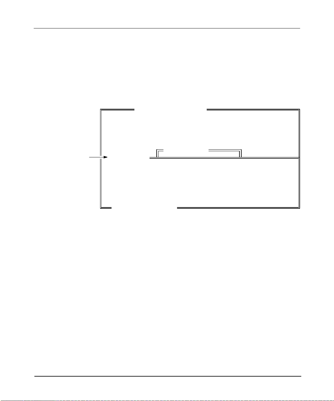
The common elements in the three formats are the keyword “SLOT” and the slot
number. The slot number defines the location of the module. The first slot of the
first chassis, slot 0, always contains the CPU module. The lar
gest possible slot
number for fixed style hardware is 2; for modular style hardware it is 30. Determine
the number of configurable slots by the number and types of chassis used. See
figure 5.1.
Figure 5.1
Determining the Slot Number of a 10–Slot Chassis (1747–A10)
192
SLC 500 Processor
(Slot Number 0)
To complete the I/O slot configuration, use one of the three formats specified in
table 5.L. See table 5.P for examples of the I/O slot configuration formats.
Table 5.P
Example I/O Slot Configuration Formats
Format: Example of Format:
1 SLOT 1 1746-IM8
2
3 SLOT 3 15900 32 5 SCAN IN 12 SCAN OUT 2 ISR 5
SLOT 2 15535 SCAN_IN 0 SCAN_OUT 10 M1_SIZE 400 M0_SIZE
800 ISR 6 G_FILE 5 0x0000 0x0010 0xfff 0x2383 0x7823
5-17
Page 53

APS Import/Export Utility User Manual
Preface
Configuring the Data Table Lists
The data table lists define the SLC 500 data table. There are two ways that
addresses are defined. Y
ou can:
• let the import utility define the file type and lar
is empty
OR
gest address when the data table
• enter the data table and describe each data file. This section will help you
accomplish this task.
The data table is the list of data files that the processor uses. The data file format
consists of the keyword DA
addresses and files may also be entered with a value list.
TA and a logical address or logical file. Logical
5-18
Page 54

Defining the Logical Address
The logical address consists of the file type, file number, a delimiter (a colon or
semicolon) and the lar
Logical Address
DATA N 7 : 5 1 2 3 4 5 6
gest logical address. For example:
Creating an
ASCII
Archive File
File Type
File Number
Data File Addressing
If you precede the logical address with three periods (...), the import utility places
the data contained in the value list into the data file starting at the logical address.
Otherwise, the import utility places the data contained in the value list into the data
file starting at word 0. The import utility determines the correct size for the file
based on the number of data elements in the value list.
String File Addressing
When defining a String (ST) file address, you must precede the file type with three
periods (such as DA
number [respectively], ranging from ST9:0–ST9:255 through ST255:0–ST255:255).
Delimiter
Largest Logical Address
TA ...ST#:# where the #s are the file number and element
5-19
Page 55

APS Import/Export Utility User Manual
Preface
Defining the Logical File
The logical file consists of only the file type and data file number. For example:
Logical File
DATA N 7:5 1 2 3 4 5 6
File Type File Number
If you supply only the file type and number (a logical file), the import utility
calculates the correct data table size for the file.
Defining the Value List
The value list defines the initial values for the data table file. Y
ou can leave the
value list empty or supply immediate values. See the example below; it shows a
value list with immediate values.
Value List
DATA N 7:5 1 2 3 4 5 6
If
you leave the value list empty
, the import utility creates the data table specified by
the logical address. The import utility then initializes the data file with zeros. For
example, the data file “DAT
A N10:5” would create data table N10 and allocate six
words of data with zeros for data values.
The import utility adjusts the size of the data table to fit all data table values. You
can enter initial data values using binary, decimal, hex, or octal format. (Enter
formats in upper or lower case letters.)
5-20
Page 56

Important Notes on Data Table Files
Read these notes before entering the data table files.
Creating an
ASCII
Archive File
• Input
and
output data tables are initialized one slot at a time. Therefore, the I/O
configuration, not the value list, determines the data table size for output and
input files.
• The data table files of a MicroLogix 1000 controller are fixed in type and size.
You can use the value list only to initialize or alter the data values of a
MicroLogix 1000 controller.
• You cannot provide initializing data for M0 and M1 files.
• The processor type determines the size of the Status file (S2). The fixed
controllers and SLC 5/01 processors have 16 elements, the SLC 5/02 processors
and MicroLogix 1000 controllers have 33 elements, the SLC 5/03 processors
have 83 elements, the SLC 5/04 OS400 processors have 87 elements, and the
SLC 5/04 OS401 processors have 164 elements. The value list does not alter
the data table size of the Status file (S2). There is no range checking done of
Status file values.
• Y
ou can enter a logical address to the element level only
ignores subelement and bit addresses. See table 5.Q for an example of valid
and invalid logical addresses.
Table 5.Q
Valid and Invalid Logical Addresses
Valid Logical Addresses: Invalid Logical Addresses:
T4:10 T4:10.PRE
T4:0 T4:0.ACC/10
I1:0 I1:0.3/10
. The import utility
To define the data file, follow these steps:
1. Enter the keyword DATA.
2. Complete the data file using the data file formats shown in table 5.R.
5-21
Page 57

APS Import/Export Utility User Manual
Preface
Table 5.R
Data File Formats and Examples
Data File Format:
Examples of Data File
Entries:
The Example Data File Entry
Creates:
See the following
screen:
DATA logical_address DATA N7:5 n7:0-5, initializes all to zero 1
DATA logical_file DATA N7 n7:0, n7:0 = 0 2
DATA Logical_address Value_list DATA N7:5 1 2 3 4 5 n7:0-5, n7:0 = 1, n7:1 = 2, etc. 3
DATA Logical_file Value_list DATA N7 1 2 3 4 5 n7:0-4, n7:0 = 1, n7:1 = 2, etc. 4
DATA . . . Logical_address Value_list DATA . . . N7:5 5 6 n7:0-6, n7:0-4 = 0, n7:5 = 5, 6 = 6 5
The following screens show you how the APS data monitor displays the data file
examples in table 5.R.
Screen 1
Command
N7:5
Screen 2
Command
N7
Screen 3
Command
N7:512345
Screen 4
Command
N712345
Address 0123456789
N7:0 000000
Address 0123456789
N7:0 0
Address 0123456789
N7:0 123450
Address 0123456789
N7:0 12345
5-22
Screen 5
Command
. . . N7:556
Address 0123456789
N7:0 0000056
Page 58

Example Data Files
%
Creating an
ASCII
Archive File
The following examples show initial data values in decimal, hex and octal formats.
The comments between the percent signs (%) explain each of the formats.
DATA N7:16 !Initial Data Values in Decimal Format
% The import utility allocates data elements N7:0 to N7:16, which are
initialized to zero if they do not exist %
% The import utility places 5249 into the data file at address N7:16 %
% The import utility places 110 into the data file at address N7:31 %
524905490 000100
–16 0 81 0 0 110
DATA N7:37 !Initial Data Values in Hex Format
% The import utility allocates data elements N7:0 to N7:37, which are
initialized to zero if they do not exist %
% The import utility places 0X1111 into the data file at address N7:0 %
% The import utility places 0X2323 into the data file at address N7:31
0X1111 0X0000 0X0000 0X0000 0X0000 0X0000 0X0000
0X0000 0X0000
0X0000 0X0000 0X0000 0X0000 0X0000 0X0000 0X0000
0X0000 0X0000
DATA I:1 !Initial Data Values in Octal Format
% Since four words of input are given, there are four words of input
configured for slot 1 %
% The import utility places 00000043 into the data file at address
I:1.0 %
% The import utility places 0O170000 into the data file at address
I:1.3 %
0O000043 0O000000 0O000021 0O170000
Defining Timers, Counters, and Control Data Files
Enter Timer (T) and Counter (C) data in the following order: CTL, PRE, and ACC.
For example:
DATA T4:0 0XE000 100 0
5-23
Page 59

APS Import/Export Utility User Manual
Preface
Notice in the preceding example that “0XE000” indicates that control bits EN, TT
and DN are set to one.
Enter the contRol (R) data values in the following order: CTL, LEN and POS. The
import utility does not prevent undefined control bits from being set. Providing data
for undefined control bits does not affect a program.
The control word (CTL) defines the control bits for timers (T), counters (C) and
control (R) file. See tables 5.S, T
Table 5.S
Control Bits for Timers Defined by the Word CTL
Bit Address Bit Name Bit Number
T4:0/EN Enable 15
T4:0/TT Timing 14
T4:0/DN Done 13
Table 5.T
Control Bits for Counters Defined by the Word CTL
, and U.
5-24
Bit Address Bit Name Bit Number
C5:0/CU Counter up enable 15
C5:0/CD Counter down enable 14
C5:0/DN Done; accumulator w preset value 13
C5:0/OV Overflow 12
C5:0/UN Underflow 11
C5:0/UA Update accumulator (HSC only) 10
C5:0/HP Accumulator w hi preset (MicroLogix 1000 controller HSC only) 9
C5:0/LP Accumulator v lo preset (MicroLogix 1000 controller HSC only) 8
C5:0/IV Overflow interrupt (MicroLogix 1000 controller HSC only) 7
C5:0/IN Underflow interrupt (MicroLogix 1000 controller HSC only) 6
C5:0/IH Hi preset interrupt (MicroLogix 1000 controller HSC only) 5
C5:0/IL Lo preset interrupt (MicroLogix 1000 controller HSC only) 4
C5:0/PE User interrupt pending (MicroLogix 1000 controller HSC only) 3
C5:0/LS User interrupt is lost (MicroLogix 1000 controller HSC only) 2
C5:0/IE Interrupt enable (MicroLogix 1000 controller HSC only) 1
Page 60

Table 5.U
Control Bits for Control Files Defined by the Word CTL
Bit Address Bit Name Bit Number
R6:0/EN Enable 15
R6:0/EU
R6:0/DN
R6:0/EM
R6:0/ER Error 11
R6:0/UL Unload 10
R6:0/IN
R6:0/FD Found 08
➀
When CTL is used with an ASCII instruction.
Enable Unload -or- Queued
Done -or- Asynchronous Done
Empty -or- Synchronous Done
Inhibit -or- Running
Entering the Project Name and Program File List
Creating an
➀
➀
➀
➀
14
13
12
09
ASCII
Archive File
The project name format consists of the keyword “PROJECT”, pr
program
PROJECT
Keyword
file number
Project Name
and program filename. For example:
“AB” 2
“POWERUP”
Program Filename
Program File Number
oject name
,
Use up to eight alphanumeric, underscore, or IBM–extended characters, in any
combination, to specify the project name. If the project name does not match the
filename of the archive file, or if the project name is left blank, the import utility
uses the name of the archive file.
The list of program file numbers and names, if included, follows the project name.
You must specify the file number first, then the filename.
The file number is an immediate integer value (2–15 for MicroLogix 1000
controllers; 2–255 for all other controllers and processors). You do not have to
specify the program file numbers in order
You specify the program filename like the project name. Y
, for example: 2 “AB” 5 “A” 3 “B”.
ou may use up to ten
characters.
5-25
Page 61

APS Import/Export Utility User Manual
Preface
Specifying the Ladder Program Files
The ladder program filename consists of the keyword “LADDER,” the file number
and, if included, the
rung list
. For example:
LADDER
Keyword Ladder File Number
If you leave the rung list empty, the import utility creates the EOR instruction.
For MicroLogix 1000 controllers, files 2 to 15 are fixed ladder program files. For
all other controllers and processors you can specify program files 2 to 255 as ladder
program files.
A rung may consist of the following:
3 SOR OTE B/0 EOR
Rung List
• start of rung symbol (SOR)
• input instructions
• output instructions
• end of rung symbol (EOR)
The import utility processes the rung left–to–right and top–to–bottom. Also, the
import utility processes each branch structure before proceeding to the next
instruction on a given line.
5-26
The ladder rung consists of three basic structure types described in table 5.V. Figure
5.2 shows a simple program before and after the import utility converts it from an
ASCII program file into an APS ladder program. Notice how the instructions and
structures in table 5.V correspond to the instructions in the ASCII program file and
the rung structures in the APS ladder program in figure 5.2.
Page 62

Table 5.V
The Branch Types of the Ladder Rung
Creating an
ASCII
Archive File
Notice this same
instruction in the
ASCII Program
File in Figure 5.2:
Structure
Types:
Branch Type
defined in
ASCII:
Branch Start BST BST A
Next Branch NXB B NXB
Branch End BND C BND
Figure 5.2
Illustrating the Branch Types of the Ladder Rung
ASCII Program File
SOR BST A
NXB
B NXB
C BND
D
EOR
Branch Type in APS ladder
programming:
APS Import Utility
converts ASCII
Program File into
APS Ladder Program.
Notice this same branch type in
the APS Ladder Program in
Figure 5.2:
A
B
C
APS Ladder Program
A
B
C
D
Example ASCII Program and APS Ladder Rung
Figure 5.3 shows an example program first in ASCII file format, then in ladder
format. The program consists of an input and output instruction list. Also included
in the program is a timer instruction (TON). (You can leave the input instruction list
empty, but not the output instruction list.) Use table 5.W to understand the
comparisons made between the two programs in figure 5.3.
Note In
APS, you can nest only four levels of branches.
5-27
Page 63

APS Import/Export Utility User Manual
Preface
Table 5.W
Key to Figure 5.3
SOR BST BST XICI:3/4 NXB
Output
List
EOR
The following ASCII
Instructions (highlighted in
the ASCII program below):
Specify this designated part
of the APS ladder rung:
XIO I:3/5
XIC I:3/6
OTE O:5/6
TON T4:3 1.0 200 0 BND
Figure 5.3
Example ASCII Program File and APS Ladder Program
ASCII Program File
XIO I:3/5 BND
XIC I:3/7
XIC I:3/6 NXB
XIC I:3/6 BND
BST OTE O:5/6 NXB
TON T4:3 1.0 200 0 BND
Input
List
Rung 3:0
I:3
][
I:3
] / [
I:3
][
Input
List
I:3
4
5
6
][
7
APS Ladder Program
I:3
][
6
Output
List
O:5
()
6
TON
TIMER ON DELAY
Timer T4:3
Time base 1.0
Preset 200
Accum 0
(EN)
(DN)
5-28
Page 64

Specifying the Force Table List
The format for specifying the force table consists of the keyword “FORCE”, a force
table addr
ess
and a
value list
. For example:
Creating an
ASCII
Archive File
FORCE
Keyword Force Table Address Value List
I:4 1 2 3 4
The value list contains the force on and force off information for the specified force
table address. Y
ou do not have to specify the value list.
When specifying the force table list, use the formats in table 5.X.
Table 5.X
Force Table Formats and Examples
Force Table Formats:
FORCE Force_table_address FORCE I:4 checks if address is configured
FORCEForce_table_address Value_list FORCE I:4 1 2 I:4.0 force on = 1, force off = 2
FORCE . . . Force_table_address Value_list FORCE . . . O:7.4 1 2 O:7.4 force on = 1, force off = 2
Example Force
Table Entry:
The Example Force Table Entry
Does the Following:
Every word of I/O consists of two corresponding words of force data: one word of
force on data and one word of force off data. Force data tables start with the force
on word, followed by the corresponding force off word. Initialize the force data
tables one slot at a time.
In the following example, the force address “FORCE I:4” initializes the first three
words of input force data for slot four, forcing bits I:4.0/0 and I:4.1/4 off, while
forcing bits I:4.2/0 and I:4.2/1 on. (This example assumes that you configured three
or more words of input for slot four.)
5-29
Page 65

APS Import/Export Utility User Manual
Preface
FORCE I:4
% ON % % OFF %
% I:4.0 % 0x0000 0x0001
% I:4.1 % 0x0000 0x0010
% I:4.2 % 0x0003 0x0000
In this example, the force address “FORCE...O:7.4” skips over the first four words
of slot seven and forces bit O:7.4/0 off and bit O:7.5/8 on.
FORCE ...O:7.4
% ON % % OFF %
% O:7.4 % 0x0000 0x0001
% O:7.5 % 0x0100 0x0000
Specifying the Channel Configuration Data List
(SLC 5/03 and SLC 5/04 Processors Only)
The required format for specifying the channel configuration data list consists of the
keyword “CHAN_CONFIG” and a
CHAN_CONFIG
Keyword Channel Configuration Type
You
can also specify a value list, which contains the channel configuration
information for the specified channel configuration file. If you leave the list empty,
APSIE initializes a default channel configuration file.
Note While the APSIE utility verifies that the driver (as encoded as the low byte of the
first wor
fields ar
You can also set the channel configuration file to a default driver configuration. To
do this, use the default driver keyword entry.
5-30
d) is corr
e corr
GEN
ect for the channel, it does not verify (range check) that the other
ect.
channel configuration file type. For example:
Page 66

Channel Configuration File Types
Table 5.Y defines the three file types that you can use as part of a channel
configuration data list.
Table 5.Y
File Types
Creating an
ASCII
Archive File
Default
Channel Configuration File
GEN General Configuration File
CH0SYS Channel 0 System Mode Configuration File
CH1SYS Channel 1 System Mode Configuration File
CH0USER Channel 0 User Mode Configuration File
Drivers
Types
The following are valid default driver entries:
• DH485
• DF1HD
• DF1FD
• ASCII
• SHUTDOWN
• DH+
Channel Configuration Formats
Definition
The following are valid channel configuration formats:
• CHAN_CONFIG channel_config_file_type
The example below generates a default General Configuration File.
CHAN_CONFIG GEN
5-31
Page 67

APS Import/Export Utility User Manual
Preface
• CHAN_CONFIG channel_config_file_type default_driver
The example below generates a default DH485, Channel 0 SYSTEM Mode
Configuration File.
CHAN_CONFIG CH0SYS DH485
• CHAN_CONFIG channel_config_file_type value_list
The example below generates a General Configuration File with a value list.
CHAN_CONFIG GEN
0x0001 0x0002 0x0003 0x0004 0x0005 0x0006
0x0007 0x0008 0x0009 0x000A 0x000B 0x000C
Specifying the Adjustable Input Filters List
(MicroLogix 1000 Controllers Only)
The format for specifying the input filters list consists of a keyword
INPUT_FILTERS and a
value list
. For example:
5-32
INPUT_FILTERS 1 2 3
Keyword Value List
The value list represents the maximum on delay for the filters in ms, as shown in
table 5.Z.
Page 68

Table 5.Z
Value List Options
Creating an
ASCII
Archive File
Value List
0 .075
1 .5
2 1
3 2
4 4
5 8
6 16
7 .1
8 .25
Maximum on Delay
for Filters (ms)
If you do not use the keyword INPUT_FILTERS, or if you leave the value list
empty, APSIE initializes a default input filter setting.
The following are valid input filter formats:
• EMPTY
The example below generates a default that sets all filters to 8 ms.
!
• INPUT_FILTERS EMPTY
The example below generates a default that sets all filters to 8 ms.
!INPUT_FILTERS
• INPUT_FILTERS value list
The example below sets the filters to .5 ms, 1 ms, 2 ms.
!INPUT_FILTERS 1 2 3
5-33
Page 69

APS Import/Export Utility User Manual
Preface
Specifying the Multi-Point I/O List
In the APS Import/Export Utility, the multi-point I/O list has been added to the
ASCII archive file for use with the SLC 5/03 OS302 and SLC 5/04 OS401
processors, and MicroLogix 1000 controllers.
The format for specifying the multi-point I/O list consists of a keyword
MULTIPOINT and a bit position, bit addr
description. For example:
MULTIPOINT
Keyword
Bit Position
There are 0–15 bit positions for MicroLogix 1000 controllers, and 0–31 bit positions
for SLC 5/03 OS302 and SLC 5/04 OS401 processors. An error occurs if you:
•
assign duplicate bit positions
0 B3:1 1 “pilot light on” “pilot light off”
Bit
Address
ess, access flag, on description, and off
On Description
Off Description
Access
Flag
5-34
• specify more than 16 value pairs
• use a bit address that is invalid for the selected controller
•
assign invalid state
If you do not use the keyword MULTIPOINT, or if you leave the value list empty,
APSIE initializes a default list of null values.
Page 70

Creating an
ASCII
The following are valid multi-point I/O formats:
• EMPTY
The example below generates a default list of null values.
!
• MULTIPOINT
EMPTY
The example below generates a default list of null values.
!MULTIPOINT
• MULTIPOINT
value list
The example below shows two entries in the list; all other positions in the list
default to null values.
!MULTIPOINT
1 N7:2/12 0 “on description” “off description”
3 C5:0/IH 1 “on description” “off description”
Archive File
5-35
Page 71

APS Import/Export Utility User Manual
Preface
Protecting Archive Files (SLC 5/03 and SLC 5/04 Processors Only)
There are three types of file protection: data, ladder, and force.
Data File Protection
To protect a data file, place the keyword entry at the end of the data file. For
example:
PROTECT_DATA N7 STATIC
Keyword Logical File Protection Type
Note Default
The following are example data file protection entries:
•
The example below causes data file B3 to be CONST
PROTECT_DATA B3 CONSTANT
• The
PROTECT_DATA N7 STATIC
• The
PROTECT_DATA N7 MEM_MOD
data file pr
example below causes data file N7 to be ST
example below causes data file N7 to be MEMory MODule protected.
otection is: output file = STATIC; all other files = unprotected.
ANT protected.
ATIC protected.
5-36
Page 72

Ladder File Protection
To protect a ladder file, place the keyword entry at the end of the ladder file. Also,
you cannot set file protection in a program that has edit zones from an online editing
session. (The APS default for file protection is no program files protected.) Use the
following format:
PROTECT_LAD 3
Keyword File Number
The example above causes program file 3 to be protected.
Force File Protection
Force
files can be protected against changes by using the PROTECT_FORCE
keyword, as shown here:
Creating an
ASCII
Archive File
PROTECT_FORCE
Note This
Keyword
keywor
d globally pr
otects all for
ce files.
5-37
Page 73

APS Import/Export Utility User Manual
Preface
Examining ASCII Archive Files
This
section provides you with two example programs, each shown as an ASCII
archive file and, for comparison, as an APS ladder program.
Example Program #1
The following program example has two rungs. The first rung has a timer
instruction, the second a nested branch.
APS Ladder Program
File 2: Rung 0
Rung
I:1
][
4
I:1
] / [
5
1
I:1
][
2
I:1
][
7
I:1
][
6
TON
TIMER ON DELAY
Timer T4;3
Time base 1.0
Preset 200
Accum 10
O:3
][
(EN)
(DN)
0
5-38
Rung 2
B3
][
B3
][
1
SQC
0
B3
] / [
2
B3
][
B3
][
6
B3
] / [
B3
][
3
B3
] / [
7
9
B3
][
4
8
SEQUENCER COMPARE
File #N7:0
Mask FFFF
Source C5:0.ACC
Control R6:0
Length 10
Position 20
(EN)
(DN)
(FD)
Page 74

ASCII Archive File
START 1747–L524
RACK 1 1746–A4
SLOT 1 1746–IM8
SLOT 2 1746–NI4
SLOT 3 1746–OA8
DATA O:3
0X0001 %Bit O:3.0/0 initialized to 1%
DATA ...T4:3
0XC000 100 25 % T4:3 CTL bits cleared
T4:3.PRE = 100 T4.3.ACC = 25 %
PROJECT “EX”
LADDER 2 % FILE 2 %
!RUNG 0
SOR BST XIC I:1/4 NXB
EOR
!RUNG 1
SOR XIC I:1/2 OTE O:3/0 EOR
FORCE I:1
FORCE O:3
XIO I:1/5 BND
XIC I:1/7 XIC I:1/6 TON T4:3 1.0 200 10
Creating an
ASCII
Archive File
!RUNG 2
SOR BST XIC B3/0 NXB
EOR
XIC B3/1
BST
XIO B3/2 BST
XIC B3/6 NXB
XIO B3/9 BND
XIO B3/7 NXB
XIC B3/3
XIC B3/4
XIC B3/8 BND
BND
SQC #N7:0 0xFFFF C5:0.ACC R6:0 10 20
5-39
Page 75

APS Import/Export Utility User Manual
Preface
Example Program #2
This example provides you with a longer and more complex program. The key
feature of this program is its subroutine.
Example program #2 in APS ladder format.
File 2: Rung 0
MEQ
MASKED EQUAL
Source B3:55
Mask B3:56
Compare 8754
B3
][
0000000000000000
1
APS
0000
B3
] / [
2
Ladder Program
B3
][
3
B3
][
0
B3
()
99
ADD
ADD
Source A N7;0
0
Source B 50
Dest N7;1
0
SUB
5-40
Rung
1
NOT EQUAL
Source A N7:0
Source B 100
Rung
2
[LBL]
Rung 3
NEQ
SUB
Source A N7;2
0
Source B N7;3
0
Dest N7;0
0
JSR
JUMP TO SUBROUTINE
SBR file number 4
0
5
JENDJ
N7:0
()
15
Page 76

File 4: Rung 0
Rung 1
Rung 2
JENDJ
Creating an
ADD
Source A N7;1
Source B N7:2
Dest N7;3
RETURN
ASCII
ADD
RET
Archive File
0
0
0
5-41
Page 77

APS Import/Export Utility User Manual
Preface
ASCII Archive File
% PROCESSOR CONFIGURATION INFORMATION %
START 1747–L511 % 1747–L511 5/01 CPU – 1K USER MEMORY %
% PROCESSOR CHASSIS CONFIGURATION INFORMATION %
RACK 1 1746–A10 % 10–Slot Backplane %
% SLOT CONFIGURATION INFORMATION %
SLOT 2 1746–NIO4I % Combo Analog 2 in 2 Out Current %
SLOT 3 1746–IA16 % 16 pt. 120 VAC Input %
SLOT 5 1747–DCM–FULL % Full Chassis DCM %
SLOT 7 2323
SLOT 8 1746–IA16 % 16 pt. 120 VAC Input %
% DATA TABLE INFORMATION %
DATA O:02
% O:2.0 % 0x0000 0x0000
DATA O:05
% O:5.0 % 0x0000 0x0000 0x0000 0x0000 0x0000 0x0000 0x0000 0x000
0
DATA O:07
% O:7.0 % 0x000
DATA I:02
% I:2.0 % 0x0000 0x0000
DATA I:03
% I:3.0 % 0x000
DATA I:05
% I:5.0 % 0x0000 0x0000 0x0000 0x0000 0x0000 0x0000 0x0000 0x000
0
DATA I:07
% I:7.0 % 0x000
DATA I:08
% I:8.0 % 0x00
DATA S:0
% S:0 % 0 1 0 2560 0 0 0 0
% S:8 % 0 0 0 –1 –1 0 0 1025
DATA B3:00
% B3:00 % 0 0 0 0 0 0 0 0
% B3:08 % 0 0 0 0 0 0 0 0
% B3:16 % 0 0 0 0 0 0 0 0
% B3:24 % 0 0 0 0 0 0 0 0
% B3:32 % 0 0 0 0 0 0 0 0
% B3:40 % 0 0 0 0 0 0 0 0
% B3:48 % 0 0 0 0 0 0 0 0
% B3:56 % 0 0 0 0 0 0 0 0
DATA N7:00
% N7:0 % 0 0 0 0
5-42
Page 78

% PROJECT AND LADDER FILENAMES %
PROJECT EXAMPLE2 2 “MAIN_PROG” 4 “SUBR_4”
% Ladder File Information %
LADDER 2
% RUNG 0 %
SOR BST
% RUNG 1 %
SOR NEQ N7:0 100 JSR 4 EOR
% RUNG 2 %
SOR LBL 5 OTE N7:0/15 EOR
LADDER 4
% RUNG 0 %
SOR ADD N7:1 N7:2 N7:3 EOR
% RUNG 1 %
SOR RET EOR
% FORCE TABLE INFORMATION %
FORCE O:2
% ON OFF %
0x0000 0x0000 % FORCE O:2.0 %
% 0x0000 0x0000% FORCE O:2.1 %
FORCE O:5
% ON OFF %
0x0000 0x0000% FORCE O:5.0 %
0x0000 0x0000% FORCE O:5.1 %
0x0000 0x0000% FORCE O:5.2 %
0x0000 0x0000% FORCE O:5.3 %
0x0000 0x0000% FORCE O:5.4 %
0x0000 0x0000% FORCE O:5.5 %
0x0000 0x0000% FORCE O:5.6 %
0x0000 0x0000% FORCE O:5.7 %
FORCE O:7
% ON OFF %
0x0000 0x0000% FORCE O:7.0 %
FORCE I:2
% ON OFF %
0x0000 0x0000% FORCE I:2.0 %
0x0000 0x0000% FORCE I:2.1 %
FORCE I:3
% ON OFF %
0x0000 0x0000% FORCE O:7.0 %
FORCE I:5
% ON OFF %
0x0000 0x0000% FORCE O:5.0 %
0x0000 0x0000% FORCE O:5.1 %
0x0000 0x0000% FORCE O:5.2 %
0x0000 0x0000% FORCE O:5.3 %
0x0000 0x0000% FORCE O:5.4 %
0x0000 0x0000% FORCE O:5.5 %
0x0000 0x0000% FORCE O:5.6 %
0x0000 0x0000% FORCE O:5.7 %
FORCE I:7
% ON OFF %
0x0000 0x0000% FORCE I:7.0 %
FORCE I:8
% ON OFF %
0x0000 0x0000% FORCE I:8.0 %
MEQ B3:55 B3:56 8754 NXB
XIC B3/1 XIO B3/2 XIC B3/3 BND
XIC B3/0 BST
OTE B3/99 NXB
ADD N7:0 50 N7:1 NXB
SUB N7:2 N7:3 N7:0 BND
EOR
Creating an
ASCII
Archive File
5-43
Page 79

Creating an
ASCII Documentation File
6
Creating an ASCII Documentation
File
This chapter shows you how to create your own ASCII documentation file. Y
use these documentation files with the import utility
following sections:
• creating ASCII documentation files
• examples of ASCII documentation files
. This chapter consists of the
ou can
6-1
Page 80

APS Import/Export Utility User Manual
Preface
Creating an ASCII Documentation File
When creating an ASCII documentation file, follow these guidelines:
• To create the file, use a text editor that produces only printable ASCII
characters, with no control or hidden characters.
•
Do not use graphics characters. IBM extended characters can be used within
comment strings and as part of symbols.
The ASCII documentation file may contain one or more of the following:
•
address comments
• instruction comments
• rung comments
• symbols
You can group statements together by keyword, or begin each statement with a
keyword. The following example shows an ASCII file using grouped statements.
Notice that all symbols group together after you enter the keyword “SYM”. The
address comments follow the keyword “AC”. Y
multiple times in a file.
ou can have the keyword appear
Note You
r
ecognize that you ar
6-2
SYM
O:1.2/3 UPLOADED
O:2.1/11 EMPTY_LITE
O:10.2/4 NOZ_FILL
AC
O:11.1/6 “comment–6”
O:9.0/5 “Temporary\Storage\Point”
I:3.0/10 “Conveyor\Running”
must enter the keywor
e gr
d on a line by itself in or
ouping statements.
der for the import utility to
Page 81

Creating an
The example below shows an ASCII documentation file with a keyword for each
statement.
SYM I:0.0/0 C5UNDERFL
AC I:0.0/0 “Totalizer Pulse Counter”
IC XIO I:0.0/0 “North Cutter Running”
IC JMP 2:LBL5 “Jump to label 5”
ASCII Documentation File
Keywords
ASCII Programming Instructions
Placing Address Comments
An address comment is a text string (a maximum of 50 characters), which provides
notes or remarks for an address. To enter an address comment, keep the following
in mind:
•
Address comments should begin and end with quotation marks (“ ”), and should
follow the instruction address on the same line.
• Do not use carriage returns. If you want a carriage return to appear in a
comment, use a back slash (\) in the comment to represent a carriage return.
(Note that this back slash is considered a character in the 50–character limit.)
• Only the first 50 characters you enter are used in the comment. The
import/export utility displays 5 lines, 10 characters per line.
• If you want a quotation mark to appear in a comment, use two adjacent
quotation marks. (One of the quotation marks is considered a character in the
50–character limit.)
•
If you enter a back slash in an address comment, precede the back slash with a
tilde (∼).
ASCII Instruction Addresses
ASCII Address Comments
6-3
Page 82

APS Import/Export Utility User Manual
Preface
These are example address comments:
AC I:0.0/0 “UPPER LOADER HYDRAULIC SOLENOID”
AC I:0.0/1 “OUT OF TOLERANCE ALARM ACKNOWLEDGE”
AC I:0.0/2 “AIR STOP CLOSED LIMIT SWITCH”
Keywords
ASCII Instruction Addresses ASCII Address Comments
Placing Instruction Comments
An instruction comment is a text string (a maximum of 50 characters), which
provides notes or remarks for an address/instruction pair. The following rules apply
to instruction comments:
• Instruction comments should begin and end with quotation marks (“”), and
should follow the instruction/address pair on the same line.
• Do not use carriage returns. If you want a carriage return to appear in the
comment, use a back slash (\) in the comment to represent a carriage return.
(Note that this back slash is considered a character in the 50–character limit.)
• Only the first 50 characters you enter are used in the comment. The
import/export utility displays 5 lines, 10 characters per line.
• If you want a quotation mark to appear in your comment, use two adjacent
quotation marks. (One of the quotation marks is considered a character in the
50–character limit.)
•
If you enter a back slash in an instruction comment, precede the back slash with
a tilde (∼).
6-4
These are example instruction comments:
IC XIC N7:10/0 “Surge Tank High Level Alarm”
IC LBL 3:LBL10 “Label 10 in ladder file 3”
IC OTE O:6.1/10 “North Cutter Running”
Keywords
ASCII Programming Instructions
ASCII Instruction Addresses
ASCII Instruction Comments
Page 83

Placing Rung Comments
A rung comment is a text string, (up to six lines long, 80 characters each), which
provides notes or remarks for an output instruction/address pair
help identify rungs. The following rules apply to rung comments:
•
Rung comments should follow the instruction/address pair on the same line.
Start rung comments with opening quotation marks (“) followed by a carriage
return and end with closing quotation marks (”).
• If you want a carriage return to appear in the comment, use a back slash (\).
(Note that this back slash is considered a character in the 80–character limit.)
• If you enter a quotation mark in the middle of a rung comment, use two
adjacent quotation marks. The initial and ending quotation marks are not
included in the comment. (One of the quotation mark is considered part of the
80–character limit.)
• If you enter a back slash in a rung comment, precede the back slash with a tilde
(∼).
The following are example rung comments:
ASCII Instruction Addresses
Creating an
ASCII Documentation File
. Rung comments
ASCII Programming Instructions
Keyword
RC OTE N7:10/0 “(carriage return)
This is an example of a rung comment with quotation
marks and carriage returns at the beginning and end.
This comment is three lines long.”
RC JMP 2:LBL5 “(carriage return)
And here is an example of “ ” and\ a back slash (use the
~ to print a back slash) without a comment:
~\IPDS~\ATTACH~\SLC500. This comment is four lines
long.”
ASCII Rung Comment
6-5
Page 84

APS Import/Export Utility User Manual
Preface
Placing Symbols
A
symbol is a 10–character name associated with an address. IBM extended
characters can be used as part of symbols.
You start a symbol with a letter from A to Z. T
o complete the symbol, you can use
any combination of ASCII characters except 0x00 through 0x2F and 0x3A through
0x3F.
The following are examples of symbols:
ASCII Address Symbols
ASCII Instruction Addresses
Keywords
SYM O:3.1/8 UPLOAD
SYM O:5.2/3 EMPTY_LINE
SYM I:1.1/8 PALLET
6-6
Page 85

Annotating ASCII Documentation Files
Creating an
ASCII Documentation File
You can add comments anywhere in the ASCII documentation file. T
o add a single
line comment, place the comment after an exclamation mark (!). In this case, the
import utility ignores all text after the exclamation mark on that line.
You may also enter comments in the ASCII documentation file by inserting the
comment between two percent signs. (Tabs, carriage returns or spaces before and
after the percent signs are optional.) For example: % This is a comment %.
You may include one or more carriage returns in a comment.
Enter comments on a single line or several lines by themselves, or directly following
a complete ASCII command. If the import utility encounters a comment character
(% or !) between quotation marks, or a rung/instruction/address comment, it
considers the comment character as part of the rung/instruction/address comment.
The following example shows you how the import utility displays comments.
Notice that the comments used to document ASCII files only describe those files.
The import utility does not store these comments in the database.
!Begin import file comments with an exclamation
!mark. as you see here. You can document your A-B
!ASCII file as you would a program.
SYM I:1.1/8 PALLET !This is a comment after a complete line.
SYM %This is a comment% I:1.1/5 %This is another comment% HI_ALARM
%This is a comment that spans
multiple lines%
6-7
Page 86

APS Import/Export Utility User Manual
Preface
Example ASCII Documentation File
This example ASCII documentation file shows you how the import utility places
comments (address, instruction, and rung) and symbols on the APS ladder rung.
(The ASCII documentation files are grouped by keyword.)
!This is a sample of a complete ASCII documentation file.
SYM
O:3.1/8 UPLOAD
O:5.2/3 EMPTY_LITE
I:1.1/8 PALLET
IC
XIC N7:10/0 “Surge Tank High Level Alarm”
XIO I:3.2/4 “Selector Switch Panel W North Cutter”
OTE O:6.1/10 “North Cutter Running”
PALLET UPLOAD
I:1.1
][
8
Surge Tank High
Level Alarm
N7:10
][
0
APS Ladder ProgramASCII Documentation File
Selector Switch
Panel W North Cutter
I:3.2
] / [
4
O:3.1
()
8
EMPTY_LITE
O:5.2
()
3
North Cutter
Running
O:6.1
()
10
AC
O:2.1/3 “UPPER LOADER HYDRALIC SOLENOID”
I:3.2/6 “OUT OF TOLERANCE ALARM ACKNOWLEDGE”
I:6.1/10 “AIR STOP CLOSED LIMIT SWITCH”
RC OTE N7:10/0
“This sample rung comment is
two lines long.”
6-8
UPPER LOADER
HYDRALIC
SOLENOID
O:2.1
][
3
Rung 2.0
This sample rung comment is
two lines long.
AIR STOP CLOSED
LIMIT SWITCH
I:6.1
][
10
OUT OF TOLERANCE
ALARM
ACKNOWLEDGE
O:3.2
()
6
N7:10
()
0
Page 87

Programming Instruction References
A
Programming Instruction
References
This appendix lists all of the available programming instructions along with their
parameters, valid addressing modes, and file types.
A-1
Page 88

APS Import/Export Utility User Manual
Preface
Valid Addressing Modes and File Types
The following addressing modes are available:
Addressing Mode Example
Direct N7:0
Indexed Direct #N7:0
Indexed N7:[N10:3]
Indexed Indirect #N7:[N10:3]
The following file types are available:
• O Output
• I Input
• S Status
• B Binary
• T Timer
• C Counter
• R Control
• N Integer
• F Float
• A ASCII
• ST String
• M M0/M1
•
Immediate – indicates that a constant is a valid file type
➀
➀
➀
➁
A-2
➀
Supported
➁
Not supported by MicroLogix 1000 controllers.
only by SLC 5/03 OS301, OS302 and SLC 5/04 OS400, OS401 processors.
Page 89

Programming Instruction References
Instruction Description Instruction
Parameter
ABL
➀
ASCII Test Buffer for
channel 0
Line
control direct R none
characters 0-1024
ABS
➁
Absolute Value source direct, indexed direct
destination direct, indexed direct
ACB
➀
ASCII Number of
channel 0
Characters in Buffer
control direct R none
characters 0-1024
ACI
➀
ASCII String to Integer source direct, indirect ST none
destination direct, indexed direct
ACL
➀
ASCII Clear Buffer channel 0
Valid Addressing
Mode(s)
indirect, indexed indirect
indirect, indexed indirect
indirect, indexed indirect
Valid File Types Immediate
Values
O, I, S, B, T, C, R,
N, F, A, ST, M
O, I, S, B, T, C, R,
-32,768-32,767
fmin-fmax
none
N, F, A, ST, M
O, I, S, B, T, C, R,
none
N, A, ST, M
ACN
ACS
transmit buffer 0=no or 1=yes
receive buffer 0=no or 1=yes
➀
ASCII String
source A direct, indirect ST none
Concatenate
source B direct, indirect ST none
destination direct ST none
➁
Arc Cosine source direct, indexed direct
indirect, indexed indirect
destination direct, indexed direct
indirect, indexed indirect
➀
Supported
➁
Supported only by SLC 5/03 OS302 and SLC 5/04 OS401 processors.
only by SLC 5/03 OS301, OS302 and SLC 5/04 OS400, OS401 processors.
O, I, S, B, T, C, R,
N, F, A, ST M
O, I, S, B, T, C, R,
N, F, A, ST, M
-32,768-32,767
fmin-fmax
none
A-3
Page 90

APS Import/Export Utility User Manual
Preface
Instruction Description Instruction
Parameter
Valid Addressing
Mode(s)
ADD Add source A direct, indexed direct
indirect, indexed indirect
source B direct, indexed direct
indirect, indexed indirect
destination direct, indexed direct
indirect, indexed indirect
AEX
➀
ASCII String Extract source direct, indirect ST none
index direct, indexed direct
indirect, indexed indirect
number direct, indexed direct
indirect, indexed indirect
destination direct ST none
AHL
➀
ASCII Set/Reset
channel 0
Handshake Lines
AND mask direct, indexed direct
indirect, indexed indirect
OR mask direct, indexed direct
indirect, indexed indirect
Valid File Types Immediate
Values
O, I, S, B, T, C, R,
N, F, A, ST, M
O, I, S, B, T, C, R,
N, F, A, ST, M
O, I, S, B, T, C, R,
-32,768-32,767
fmin-fmax
-32,768-32,767
fmin-fmax
none
N, F, A, ST, M
O, I, S, B, T, C, R,
1-82
N, A, ST, M
O, I, S, B, T, C, R,
1-82
N, A, ST, M
O, I, S, B, T, C, R,
0-FFFF
N, A, ST, M
O, I, S, B, T, C, R,
0-FFFF
N, A, ST, M
control direct R none
channel status 0-001F
AIC
➀
ASCII Integer to String source direct, indexed direct
indirect, indexed indirect
destination direct ST none
AND Logical AND source A direct, indexed direct
indirect, indexed indirect
source B direct, indexed direct
indirect, indexed indirect
destination direct, indexed direct
indirect, indexed indirect
A-4
➀
Supported
only by SLC 5/03 OS301, OS302 and SLC 5/04 OS400, OS401 processors.
O, I, S, B, T, C, R,
N, A, ST, M
O, I, S, B, T, C, R,
N, A, ST, M
O, I, S, B, T, C, R,
N, A, ST, M
O, I, S, B, T, C, R,
N, A, ST, M
-32,768-32,767
-32,768-32,767
-32,768-32,767
none
Page 91

Programming Instruction References
Instruction Description Parameter Valid Addressing
Mode(s)
ARD
➀
ASCII Read Characters channel 0
destination direct ST none
control direct R none
string length 0-82
characters read 0-82
ARL
➀
ASCII Read Line channel 0
destination direct ST none
control direct R none
string length 0-82
characters read 0-82
ASC
➀
ASCII String Search source direct, indirect ST none
index direct, indexed direct
indirect, indexed indirect
search direct, indirect ST none
Valid File Types Immediate
Values
O, I, S, B, T, C, R,
1-82
N, A, ST, M
ASN
ASR
ATN
result direct, indexed direct
indirect, indexed indirect
➁
Arc Sine source direct, indexed direct
indirect, indexed indirect
destination direct, indexed direct
indirect, indexed indirect
➀
ASCII String Compare source A direct, indirect ST none
O, I, S, B, T, C, R,
N, A, ST, M
O, I, S, B, T, C, R,
N, F, A, ST, M
O, I, S, B, T, C, R,
N, F, A, ST, M
none
-32,768-32,767
fmin-fmax
none
source B direct, indirect ST none
➁
Arc Tangent source direct, indexed direct
indirect, indexed indirect
destination direct, indexed direct
indirect, indexed indirect
➀
Supported
➁
Supported only by SLC 5/03 OS302 and SLC 5/04 OS401 processors.
only by SLC 5/03 OS301, OS302 and SLC 5/04 OS400, OS401 processors.
O, I, S, B, T, C, R,
N, F, A, ST, M
O, I, S, B, T, C, R,
N, F, A, ST, M
-32,768-32,767
fmin-fmax
none
A-5
Page 92

APS Import/Export Utility User Manual
Preface
Instruction Description Parameter Valid Addressing
Mode(s)
AWA
➀
ASCII Write with
channel 0
Append
source direct ST none
control direct R none
string length 0-82
characters sent 0-82
AWT
➀
ASCII Write channel 0
source direct ST none
control direct R none
string length 0-82
characters sent 0-82
BSL Bit Shift Left file indexed direct
indexed indirect
control direct R none
bit address direct, indirect O, I, S, B, T, C, R,
Valid File Types Immediate
Values
O, I, S, B, N, A, ST none
none
N, A, ST, M
length 0-2048
BSR Bit Shift Right file indexed direct
indexed indirect
control direct R none
bit address direct, indirect O, I, S, B, T, C, R,
length 0-2048
CLR Clear destination direct, indexed direct
indirect, indexed indirect
A-6
➀
Supported
only by SLC 5/03 OS301, OS302 and SLC 5/04 OS400, OS401 processors.
O, I, S, B, N, A, ST none
none
N, A, ST, M
O, I, S, B, T, C, R,
none
N, F, A, ST, M
Page 93

Programming Instruction References
Instruction Description Parameter Valid Addressing
Valid File Types Immediate
Mode(s)
COP Copy File source indexed direct
indexed indirect
destination indexed direct
indexed indirect
O, I, S, B, T, C, R,
N, F, A, ST, M
O, I, S, B, T, C, R,
N, F, A, ST, M
none
none
length 1-128
COS
CPT
➁
➁
Cosine source direct, indexed direct
indirect, indexed indirect
destination direct, indexed direct
indirect, indexed indirect
Compute destination direct, indexed direct
indirect, indexed indirect
O, I, S, B, T, C, R,
N, F, A, ST, M
O, I, S, B, T, C, R,
N, F, A, ST, M
O, I, S, B, T, C, R,
N, F, A, ST, M
-32,768-32,767
fmin-fmax
none
none
expression <expression>
CTD Count Down counter direct C none
preset -32,768-32,767
accum -32,768-32,767
CTU Count Up counter direct C none
preset -32,768-32,767
Values
accum -32,768-32,767
DCD Decode 4 to 1 of 16 source direct, indexed direct
indirect, indexed indirect
destination direct, indexed direct
indirect, indexed indirect
DDV Double Divide source direct, indexed direct
indirect, indexed indirect
destination direct, indexed direct
indirect, indexed indirect
DEG
➁
Radians to Degrees source direct, indexed direct
indirect, indexed indirect
destination direct, indexed direct
indirect, indexed indirect
➁
Supported
only by SLC 5/03 OS302 and SLC 5/04 OS401 processors.
O, I, S, B, T, C, R,
N, A, ST, M
O, I, S, B, T, C, R,
N, A, ST, M
O, I, S, B, T, C, R,
N, A, ST, M
O, I, S, B, T, C, R,
N, A, ST, M
O, I, S, B, T, C, R,
N, F, A, ST, M
O, I, S, B, T, C, R,
N, F, A, ST, M
none
none
-32,768-32,767
none
-32,768-32,767
fmin-fmax
none
A-7
Page 94

APS Import/Export Utility User Manual
Preface
Instruction Description Parameter Valid Addressing
Mode(s)
DIV Divide source A direct, indexed direct
indirect, indexed indirect
source B direct, indexed direct
indirect, indexed indirect
destination direct, indexed direct
indirect, indexed indirect
ENC
➂
Encode 1 of 16 to 4
source direct, indexed direct
indirect, indexed indirect
destination direct, indexed direct
indirect, indexed indirect
EQU Equal source A direct, indexed direct
indirect, indexed indirect
source B direct, indexed direct
indirect, indexed indirect
FFL
➃
FIFO Load source direct, indexed direct
indirect, indexed indirect
FIFO array indexed direct
indexed indirect
FIFO control direct R none
Valid File Types Immediate
Values
O, I, S, B, T, C, R,
N, F, A, ST, M
O, I, S, B, T, C, R,
N, F, A, ST, M
O, I, S, B, T, C, R,
-32,768-32,767
fmin-fmax
-32,768-32,767
fmin-fmax
none
N, F, A, ST, M
O, I, S, B, T, C, R,
none
N, A, ST, M
O, I, S, B, T, C, R,
none
N, A, ST, M
O, I, S, B, T, C, R,
none
N, F, A, ST, M
O, I, S, B, T, C, R,
N, F, A, ST, M
O, I, S, B, T, C, R,
N, A, ST, M
➆
-32,768-32,767
fmin-fmax
-32,768-32,767
O, I, S, B, N, A none
FFU
A-8
length 1-128
position 0-127
➃
FIFO Unload FIFO array indexed direct
O, I, S, B, N, A none
indexed indirect
destination direct, indexed direct
indirect, indexed indirect
O, I, S, B, T, C, R,
N, A, ST, M
➆
none
FIFO control direct R none
length 1-128
position 0-127
➂
Supported only by MicroLogix 1000 controllers.
➃
Supported only by SLC 5/02, SLC 5/03, and SLC 5/04 processors and MicroLogix 1000 controllers.
➆
Indexed addressing is not allowed when using T
, C, R, or M addresses.
Page 95

Programming Instruction References
Instruction Description Parameter Valid Addressing
Valid File Types Immediate
Mode(s)
FLL Fill File source direct, indirect O, I, S, B, T, C, R,
N, F, A, ST, M
destination indexed direct
indexed indirect
O, I, S, B, T, C, R,
N, F, A, ST, M
length 1-128
FRD
From BCD to Binary
source (SLC 5/01) direct O, I, S, B, T, C, R,
N, A, ST, M
source (SLC 5/02,
SLC 5/03, SLC
direct, indexed direct
indirect, indexed indirect
O, I, S, B, T, C, R,Nnone
5/04, MicroLogix
1000 controllers)
destination direct, indexed direct
indirect, indexed indirect
GEQ Greater Than or Equal source A direct, indexed direct
indirect, indexed indirect
source B direct, indexed direct
indirect, indexed indirect
GRT Greater Than source A direct, indexed direct
indirect, indexed indirect
O, I, S, B, T, C, R,
N, A, ST, M
O, I, S, B, T, C, R,
N, F, A, ST, M
O, I, S, B, T, C, R,
N, F, A, ST, M
O, I, S, B, T, C, R,
N, F, A, ST, M
Values
-32,768-32,767
fmin-fmax
none
none
none
none
-32,768-32,767
fmin-fmax
none
HSC
HSC
HSD
HSE
source B direct, indexed direct
indirect, indexed indirect
➅
High-Speed Counter
counter none
O, I, S, B, T, C, R,
N, F, A, ST, M
-32,768-32,767
fmin-fmax
(SLC 5/01)
preset 1-32,767
➂
High-Speed Counter type 0-7
counter direct C none
preset -32,768-32,767
accum -32,768-32,767
➂
➂
HSC Interrupt Disable counter direct C none
HSC Interrupt Enable counter direct C none
➂
Supported only by MicroLogix 1000 controllers.
➅
Supported only by L20, L30, and L40 processors with DC inputs.
A-9
Page 96

APS Import/Export Utility User Manual
Preface
Instruction Description Parameter Valid Addressing
Mode(s)
HSL
➂
HSC Load counter direct C none
source direct B and N none
length always 5
➆
IID
➆
IIE
IIM Immediate Input with
I/O Interrupt Disable slots double hex word
I/O Interrupt Enable slots double hex word
slot direct I none
Mask
mask direct, indexed direct
indirect, indexed indirect
length
(SLC 5/03 and
SLC 5/04)
➃
INT
IOM Immediate Output with
I/O Interrupt none
slot direct O none
Mask
Valid File Types Immediate
Values
(list of slots)
(list of slots)
O, I, S, B, T, C, R,
-32,768-32,767
N, A, ST, M
1-32
mask direct, indexed direct
indirect, indexed indirect
length
O, I, S, B, T, C, R,
N, A, ST, M
-32,768-32,767
1-32
(SLC 5/03 and
SLC 5/04)
JMP Jump label number 0-999
JSR Jump to Subroutine subroutine file
3-255
number
LBL Label Declaration label number 0-999
➂
Supported only by MicroLogix 1000 controllers.
➃
Supported only by SLC 5/02, SLC 5/03, and SLC 5/04 processors and MicroLogix 1000 controllers.
➆
Supported only by SLC 5/02, SLC 5/03, and SLC 5/04 processors.
A-10
Page 97

Programming Instruction References
Instruction Description Parameter Valid Addressing
Mode(s)
LEQ Less Than or Equal To source A direct, indexed direct
indirect, indexed indirect
source B direct, indexed direct
indirect, indexed indirect
LES Less Than source A direct, indexed direct
indirect, indexed indirect
source B direct, indexed direct
indirect, indexed indirect
LFL
➃
LIFO Load source direct, indexed direct
indirect, indexed indirect
LIFO array indexed direct
indexed indirect
LIFO control direct R none
length 1-128
position 0-127
LFU
➃
LIFO Unload LIFO array indexed direct
indexed indirect
destination direct, indexed direct
indirect, indexed indirect
Valid File Types Immediate
Values
O, I, S, B, T, C, R,
none
N, F, A, ST, M
O, I, S, B, T, C, R,
N, F, A, ST, M
O, I, S, B, T, C, R,
-32,768-32,767
fmin-fmax
none
N, F, A, ST, M
O, I, S, B, T, C, R,
N, F, A, ST, M
O, I, S, B, T, C, R,
N, A, ST, M
➄
-32,768-32,767
fmin-fmax
-32,768-32,767
O, I, S, B, N, A none
O, I, S, B, N, A none
O, I, S, B, T, C, R,
N, A, ST, M
➄
none
LIM
LIFO control direct R none
length 1-128
position 0-127
➃
Limit Test (circ) low limit direct, indexed direct
indirect, indexed indirect
test direct, indexed direct
indirect, indexed indirect
high limit direct, indexed direct
indirect, indexed indirect
➃
Supported
➄
Indexed addressing is not allowed when using T
only by SLC 5/02, SLC 5/03, and SLC 5/04 processors and MicroLogix 1000 controllers.
, C, R, or M addresses.
O, I, S, B, T, C, R,
N, F, A, ST, M
O, I, S, B, T, C, R,
N, F, A, ST, M
O, I, S, B, T, C, R,
N, F, A, ST, M
-32,768-32,767
fmin-fmax
-32,768-32,767
fmin-fmax
-32,768-32,767
fmin-fmax
A-11
Page 98

APS Import/Export Utility User Manual
(5/02
)
Preface
Instruction Description Parameter Valid Addressing
Valid File Types Immediate
Mode(s)
LN
LOG
➁
➁
Natural Log source direct, indexed direct
indirect, indexed indirect
destination direct, indexed direct
indirect, indexed indirect
Log to the Base 10 source direct, indexed direct
indirect, indexed indirect
destination direct, indexed direct
indirect, indexed indirect
O, I, S, B, T, C, R,
N, F, A, ST, M
O, I, S, B, T, C, R,
N, F, A, ST, M
O, I, S, B, T, C, R,
N, F, A, ST, M
O, I, S, B, T, C, R,
N, F, A, ST, M
-32,768-32,767
fmin-fmax
none
-32,768-32,767
fmin-fmax
none
MCR Master Control Relay none
MEQ Mask Compare EqualTosource direct, indexed direct
indirect, indexed indirect
source mask direct, indexed direct
indirect, indexed indirect
compare direct, indexed direct
indirect, indexed indirect
MOV Move source direct, indexed direct
indirect, indexed indirect
destination direct, indexed direct
indirect, indexed indirect
O, I, S, B, T, C, R,
N, A, ST, M
O, I, S, B, T, C, R,
N, A, ST, M
O, I, S, B, T, C, R,
N, A, ST, M
O, I, S, B, T, C, R,
N, F, A, ST, M
O, I, S, B, T, C, R,
N, F, A, ST, M
none
-32,768-32,767
-32,768-32,767
-32,768-32,767
fmin-fmax
none
Values
MSG
Message read/write 0=read,1=write
only
target device 2=500CPU,
4=485CIF
control block direct N none
control block length 7
local address direct O, I, S, B, T, C, R,
none
N, A
target node 0-31
target address direct O, I, S, B, T, C, R,
0-255
N, A
message length
T, C, R 1-13
I, O, S, B, N 1-41
➁
Supported
A-12
only by SLC 5/03 OS302 and SLC 5/04 OS401 processors.
Page 99

Programming Instruction References
(5/03 and
Instruction Description Parameter Valid Addressing
Mode(s)
MSG
5/04 only)
Message type 64=peertopeer
read/write 0=read, 1=write
target device 2=500CPU,
local/remote 16=local,
control block direct N none
control block length 14
channel number 0 or 1
target node 0-31,
remote bridge
link ID
remote bridge
node address
local bridge node
address
Valid File Types Immediate
Values
4=485CIF,
8=PLC5
32=remote
0-254 if 485CIF
0-254,
0 when local
0-254
0 when local
0-254, 0xFFFF
when local
➇
File types F
local file address direct O, I, S, B, T, C, R,
N, F, A, ST, M
target file address direct O, I, S, B, T, C, R,
N, F, A, ST, M
message length
O, I, S, B, N, A
➇
F
➇
➇
➇
T 1-34 or
C, R 1-34
➇
ST
message timeout 0-255
, A, and ST only apply to SLC 5/03 OS301 or later and SLC 5/04.
none
0-255
1-103
1-51
if PLC5: 1-20
2 or
if PLC5: 1
A-13
Page 100

APS Import/Export Utility User Manual
Preface
Instruction Description Parameter Valid Addressing
Mode(s)
MUL Multiply source A direct, indexed direct
indirect, indexed indirect
source B direct, indexed direct
indirect, indexed indirect
destination direct, indexed direct
indirect, indexed indirect
MVM Masked Move source direct, indexed direct
indirect, indexed indirect
source mask direct, indexed direct
indirect, indexed indirect
destination direct, indexed direct
indirect, indexed indirect
NEG Negate source direct, indexed direct
indirect, indexed indirect
destination direct, indexed direct
indirect, indexed indirect
NEQ Not Equal To source A direct, indexed direct
indirect, indexed indirect
source B direct, indexed direct
indirect, indexed indirect
Valid File Types Immediate
O, I, S, B, T, C, R,
N, F, A, ST, M
O, I, S, B, T, C, R,
N, F, A, ST, M
O, I, S, B, T, C, R,
N, F, A, ST, M
O, I, S, B, T, C, R,
N, A, ST, M
O, I, S, B, T, C, R,
N, A, ST, M
O, I, S, B, T, C, R,
N, A, ST, M
O, I, S, B, T, C, R,
N, F, A, ST, M
O, I, S, B, T, C, R,
N, F, A, ST, M
O, I, S, B, T, C, R,
N, F, A, ST, M
O, I, S, B, T, C, R,
N, F, A, ST, M
Values
-32,768-32,767
fmin-fmax
-32,768-32,767
fmin-fmax
none
none
-32,768-32,767
none
none
none
none
-32,768-32,767
fmin-fmax
NOT Logical NOT source direct, indexed direct
indirect, indexed indirect
destination direct, indexed direct
indirect, indexed indirect
OR Logical OR source A direct, indexed direct
indirect, indexed indirect
source B direct, indexed direct
indirect, indexed indirect
destination direct, indexed direct
indirect, indexed indirect
OSR One-Shot Rising bit address direct, indirect O, I, S, B, T, C, R,
A-14
O, I, S, B, T, C, R,
N, A, ST, M
O, I, S, B, T, C, R,
N, A, ST, M
O, I, S, B, T, C, R,
N, A, ST, M
O, I, S, B, T, C, R,
N, A, ST, M
O, I, S, B, T, C, R,
N, A, ST, M
N, A, ST
none
none
-32,768-32,767
-32,768-32,767
none
none
 Loading...