

Page 1

Who Should Use this Manual ?...........................................................................
Purpose of this Manual ?....................................................................................
Common T echniques Used in this Manual ?.....................................................
Installing the Software 1œ1....................................................................
Personal Computer Requirements 1œ2...................................................................
Platform Restrictions 1œ3........................................................................................
Using Extended Memory 1œ4..................................................................................
Using Expanded Memory 1œ4.................................................................................
Using APS with DOS 5.0 1œ6..................................................................................
Using APS with DOS 6.0 1œ7..................................................................................
Installing the Software or Software Updates 1œ9....................................................
Configuring the Windows Drivers (INTERCHANGE) 1œ11.......................................
Running APS 1œ16...................................................................................................
Using the ReadMe File 1œ18.....................................................................................
SupportPlus Remote Software Support Disks 1œ18.................................................
Transferring the Software Ownership 1œ18..............................................................
Documentation Database Utility (UPDATEDB.EXE) 1œ19........................................
Navigating Through the Software 2œ1..................................................
Using Online Help 2œ2............................................................................................
APS Screen Format 2œ3.........................................................................................
The Five Basic Menu Displays 2œ4.........................................................................
Keys Y ou Use 2œ10.................................................................................................
Configuring Your System 3œ1...............................................................
Configuration Options 3œ2......................................................................................
Saving Y our Configuration 3œ14..............................................................................
File Extensions Used by APS and APSIE 3œ14........................................................
Ladder Logic Program Basics 4œ1.......................................................
Understanding Ladder Logic Programs 4œ2...........................................................
Types of Ladder Logic Connections 4œ5.................................................................
Application Example 4-Rung Ladder Logic Program 4œ11.....................................
Creating and Configuring Processor Files 5œ1...................................
Processor Functions 5œ2........................................................................................
Effects of Processor Type Changes 5œ9.................................................................
Deleting a Processor File from the Workspace 5œ13................................................
Archive File Operations 5œ14....................................................................................
Creating and Editing Ladder Program Files 6œ1.................................
Creating Ladder Program Files 6œ2........................................................................
Editing Ladder Program Files 6œ5...........................................................................
The Search Function 6œ12........................................................................................
Advanced Editing Functions 6œ16............................................................................
Recovering Y our Work 6œ19....................................................................................
Creating and Deleting Data Files (SLC 500 Processors Only) 6œ20........................
Page 2

Radices Used in APS 6œ24.......................................................................................
Documenting Ladder Programs 7œ1....................................................
Comment Types and Symbols 7œ2.........................................................................
Documenting Y our Ladder Program 7œ4...............................................................
Using the Database Editor 7œ16...............................................................................
Viewing Y our Documented Program 7œ25...............................................................
Protection 8œ1........................................................................................
Password 8œ2.........................................................................................................
Future Access (OEM Lock) 8œ5..............................................................................
Program Owner Protection 8œ6...............................................................................
Program File Protection (SLC 5/03 and SLC 5/04 Processors) 8œ8.......................
Data T able File Protection 8œ10...............................................................................
Memory Module Data File Overwrite (SLC 5/03 and SLC 5/04 Processors) 8œ16...
Memory Module Program Compare Protection (SLC 5/03 and SLC 5/04 8œ17.......
Memory Module Write Protection (SLC 5/03 and SLC 5/04 Processors) 8œ17........
Force Protection 8œ20...............................................................................................
Keyswitch Protection (SLC 5/03 and SLC 5/04 Processors) 8œ20...........................
Communication Channel Protection (SLC 5/03 and SLC 5/04 Processors) 8œ21....
Saving and Compiling a Processor File 9œ1........................................
Saving a Processor File 9œ2...................................................................................
Evaluating How Processor Memory is Stored 9œ8..................................................
Creating and Printing Reports 10œ1.......................................................
Types of Reports 10œ2..............................................................................................
Creating Reports 10œ4..............................................................................................
Adding Titles to Printed Reports 10œ18......................................................................
Configuring the Report Page Layout 10œ19................................................................
Printing Reports 10œ21...............................................................................................
Configuring Your Programming Device for Online 11œ1......................
Configuration Options 11œ2......................................................................................
Online Configuration 11œ5........................................................................................
Using WHO 12œ1......................................................................................
Using DH-485 WHO 12œ2.........................................................................................
Using DH+ WHO (SLC 5/04 Processors Only) 12œ13................................................
Configuring Your Processor for Online Communication 13œ1............
Configuring SLC 5/01 and SLC 5/02 Processors 13œ2.............................................
Configuring the SLC 5/03 and SLC 5/04 Processors for Online 13œ3......................
Understanding the Channel Configuration Option 13œ5...........................................
Changing the Channel Configuration 13œ9...............................................................
Changing the Communication Mode of Channel 0 13œ19..........................................
Considerations When Communicating as a DF1 Slave on a Multi-drop 13œ22..........
Page 3

Restoring and Saving Processor Files 14œ1.........................................
Communicating with a Processor 14œ2.....................................................................
Restoring a File 14œ4................................................................................................
Saving a File 14œ7....................................................................................................
Changing Processor Modes 15œ1...........................................................
Available Modes of Operation 15œ2..........................................................................
Changing Remote Modes 15œ6................................................................................
Monitoring Controller Operation 16œ1...................................................
Monitoring Program Files 16œ2.................................................................................
Monitoring an Application 16œ7.................................................................................
Fault Recovery Procedure 16œ14...............................................................................
Data T able File Displays 16œ16.................................................................................
Online Editing 17œ1..................................................................................
Overview of Online Editing 17œ2...............................................................................
Types of Online Editing 17œ5....................................................................................
Online Editing Screen Display 17œ6..........................................................................
Effects of Online Editing On Y our System 17œ9......................................................
Online Editing Functions 17œ12..................................................................................
Runtime and Program Online Editing Effects 17œ15...................................................
Performing an Online Edit 17œ18................................................................................
The Multi-Point Function 18œ1................................................................
Multi-Point Function Overview 18œ2.........................................................................
The Multi-Point List Menu 18œ3................................................................................
The Edit Fields Menu 18œ5.......................................................................................
The Multi-Point Force Menu 18œ6.............................................................................
The Force Function 19œ1.........................................................................
Force Function Overview 19œ2.................................................................................
Forcing External Input Data File Bits 19œ3................................................................
Forcing an External Output Circuit 19œ9...................................................................
Using Memory Modules (EEPROMs and UVPROMs) 20œ1...................
Using a Memory Module 20œ2..................................................................................
Transferring Files 20œ2.............................................................................................
Using the PROM Translator Function 20œ6..............................................................
Transferring Program Files 21œ1............................................................
Program Transfer Overview 21œ2.............................................................................
Transferring Programs Between Programming Terminals 21œ3...............................
APS Error Messages ?.......................................................................
Page 4

Advanced Programming Software User Manual
Preface
Who Should Use this Manual
Use this manual if you are responsible for designing, programming, or
troubleshooting control systems that use Allen-Bradley small logic controllers.
You should have a basic understanding of SLC 500t products. If you do not,
contact your local Allen-Bradley representative for the proper training before using
this product.
We recommend reviewing the
software.
Purpose of this Manual
This manual is a programming guide for the Advanced Programming Software
(APS). It describes the procedures you use to program APS. This manual:
•
gives you an overview of such topics as addressing, ladder logic, creating and
editing processor files, available processor modes, online editing, and
transferring program files.
• explains the procedures you use to program APS
• complements the online help available at the terminal
Contents of this Manual
Chapter Title Contents
Preface
1 Installing the Software
2
3 Configuring Your System
4 Ladder Logic Program Basics
Navigating Through the
Software
APS Quick Start for New Users
Describes the purpose, background, and scope of
this manual. Also specifies the audience for whom
this manual is intended.
Describes the requirements for installing and
running APS.
Discusses online help, guides you through the APS
menu displays, and explains the keys you use.
Describes how to select color options, the printer
configuration, system startup state, and
userpreferred directories.
Explains ladder programming. Includes examples
of simple rungs and 4rung programs.
before using the
P–2
Page 5

Chapter ContentsTitle
5
6
7
Creating and Configuring
Processor Files
Creating and Editing Ladder
Program Files
Documenting Ladder
Programs
8 Protection
9
Saving and Compiling a
Processor File
10 Creating and Printing Reports
Configuring Your
11
Programming Device for
Online Communications
12 Using WHO
13
14
Configuring Your Processor
for Online Communications
Restoring and Saving
Processor Files
15 Changing Processor Modes
16
Monitoring Controller
Operation
Steps you through creating and then configuring
processor files.
Shows you how to create and edit a program file.
Describes how to enter text in ladder program files
which explains the events related to a particular
rung or program.
Describes the available types of protection for each
processor.
Describes the procedures used to save and
compile a processor file.
Describes the procedure for creating and printing
reports.
Describes how to configure the terminal and
software for online communication.
Describes the DH485 and DH+ functions.
Describes how to configure the SLC 500 processor
for online communication.
Describes how to upload and download program
files.
Describes the different operating modes a
processor can be placed in while using APS.
Describes how to monitor controller operation.
17 Online Editing Describes what online editing is and how to use it.
18 The MultiPoint Function Describes the multipoint function and how to use it.
19 The Force Function Describes the force function and how to use it.
Describes the procedures used to transfer a
program to/from an EEPROM. Also describes
UVPROMs.
20
Using Memory Modules
(EEPROMs and UVPROMs)
Describes how to transfer program files between
21 Transferring Program Files
programming devices connected on a DH485
network.
Appendix A APS Error Messages
Describes possible APS error messages and their
corrective actions.
Preface
P–3
Page 6

Advanced Programming Software User Manual
Preface
Related Documentation
The following documents contain additional information concerning RSI and
Allen-Bradley SLC products. To obtain a copy
distributor.
For Read this Document
An introduction to APS for firsttime users,
containing basic concepts but focusing on simple
tasks and exercises, and allowing the reader to
begin programming in the shortest time possible
, contact your local sales of
APS Quick Start for New Users
fice or
A training and quick reference guide to APS SLC 500 Software Programmer's Quick
A guide of common procedures used in APS SLC 500 Software Common Procedures
A reference manual that contains status file data
and instruction set information for the SLC 500
processors and MicroLogix 1000 controllers.
A procedural and reference manual for technical
personnel who use the APS import/export utility to
convert APS files to ASCII and conversely ASCII to
APS files
An overview of the SLC 500 family of products SLC 500 System Overview, Publication
A description on how to install and use your Fixed
SLC 500 programmable controller
A description on how to install and use your
Modular SLC 500 programmable controller
A description on how to install and use your
MicroLogix 1000 controllers. This manual also
contains status file data and instruction set
information for the micro controllers.
Reference Guide, Publication Number
ABT1747TSG001available on PASSPORT
at a list price of $50.00
Guide, Publication Number
ABT1747TSJ50available on PASSPORT
at a list price of $50.00
Instruction Set Reference Manual
APS Import/Export User Manual
Number 17472.30
Installation and Operation Manual for Fixed
Hardware Style Programmable Controllers,
Catalog Number 1747NM001
Installation and Operation Manual for
Modular Hardware Style Programmable
Controllers, Publication Number 17476.2
MicroLogix 1000 Controllers User Manual,
Publication Number 17616.3.
P–4
A complete listing of current documentation,
including ordering instructions. Also indicates
whether the documents are available on CDROM
or in multilanguages.
A glossary of industrial automation terms and
abbreviations
AllenBradley Publication Index, Publication
Number SD499
AllenBradley Industrial Automation Glossary,
Publication Number AG7.1
Page 7

Common Techniques Used in this Manual
The following conventions are used throughout this manual:
• Bulleted lists provide information, not procedural steps.
• Numbered lists provide sequential steps or hierarchical information.
• Text in this font
• Italic
•
The following table summarizes the conventions used to distinguish the differences
between the SLC 5/03 processor and SLC 5/04 processor keyswitch positions, the
processor modes, and the actual display on the APS status line.
type is used for emphasis.
Key names match the names shown and appear in bold, capital letters within
brackets (for example, [ENTER]). A function key icon matches the name of
the function key you should press, such as
indicates words or phrases you should type.
CONFIG
SAVE
OFFLINE
EXIT
CONFIG
F3
Preface
.
When Referring
to the Keyswitch
Position
RUN position Run mode RUN
REMote position
PROGram position Program mode PROG
When Referring to the Processor
Mode
Run mode REM RUN
Program mode REM PROG
Test Single Step mode
Test Single Scan mode REM SSN
Test Continuous Scan mode REM CSN
When Referring
Status Line
REM SRG
to the
P–5
Page 8

Installing the Software
1
Installing the Software
Use the information in this chapter for information on:
• personal computer requirements
• platform restrictions
• procedures for installing APS
• configuring the windows drivers
• running APS
• SupportPlus Remote Software Support
• transferring registration information
• the documentation database utility
1–1
Page 9

Advanced Programming Software User Manual
Preface
Personal Computer Requirements
The Advanced Programming Software (APS) can be used with an Allen-Bradley
T47, T53, T60, or T70 terminal, 386/SX, NEC VERSAtE and M Series
Notebooks, or GATEWAY 2000t models 386DX/25, 386DX/33, 486DX/33,
486DX2/50, and 486DX2/66 personal computers. Your computer must have:
• 640 Kbytes of RAM (A minimum of 2 Mbytes of extended memory
is required; 3 Mbytes are required for programming a 1747-L543 processor.)
• 10 Mbytes fixed-disk drive (APS requires 7.5 MBytes of free disk space.)
• MS DOS version 3.3 or higher (INTERCHANGEt requires MS DOS version
5.0 or higher.)
•
For operation using Micr
for Workgroups version 3.11.
osoftR Windowst:
W
indows version 3.1 or Windows
Note APS
• W
• Microsoft W
• IBM OS/2
• IBM 0S/2 WARP
The amount of free conventional RAM that APS requires depends on what
communication drivers you want to load:
only the standalone communications drivers 300K bytes
Microsoft Windows drivers (INTERCHANGE software) 369K bytes
6.0 is not supported on the following operating systems:
indows 95
➀
Rockwell
was not designed for specific Windows 95 compatibility, nor has a complete set of tests within this operating
system been completed at the time of the APS 6.0 release. However, if you still want to attempt to operate
in the WIndows 95 operating system, there is some background information provided for you in the APS
ReadMe file.
➀
indows NT
Software does not recommend the use of APS 6.0 in the Windows 95 operating system. APS 6.0
If you want to load: You need:
t351
1–2
Page 10

Platform Restrictions
If Using a 386/DX33 or Higher Platform
These platforms operate with no restrictions.
If Using a Platform Lower Than 386/DX33
Some restrictions may apply when operating at these platforms depending on the
communication driver you use and its associated baud rate.
When operating at 19200 with an Allen-Bradley T47 or T60, a 386SX, or a similar
computer, the use of EMM386 may slightly degrade network communications, and
may degrade the reliability of APS communications to a network node. For
enhanced communications performance on these computers, we recommend you
remove EMM386 from the CONFIG.SYS file.
For restrictions on other drivers, see the table that follows.
Baud Rate
Platform
386/DX25
386/SX16 ■ ▲
19200 9600 4800 2400 19200 9600
▲
Communication Driver
KF3/KE and DF1
Half-Duplex
Installing the Software
Windows 485
(PIC Only)
▲ ▲
■
■
Communication
▲
Communication between the driver and APS is only supported without an expanded memory manager
■
Communication between the driver and APS is not supported.
between the driver and APS is supported with or without an expanded memory manager
.
.
Note Using a platform lower than a 386/SX16 is not supported online or offline.
1–3
Page 11

Advanced Programming Software User Manual
Preface
Using Extended Memory
APS requires a minimum of 3 Mbytes of extended memory (XMS). T
extended (XMS) memory, add the following command to your CONFIG.SYS file:
Type: DEVICE=HIMEM.SYS
If the file HIMEM.SYS is not located in your root directory (C:\), you must specify
the directory path to the file so DOS can locate the file (for example, DEVICE =
C:\DOS\HIMEM.SYS).
If you use HIMEM.SYS, we strongly recommend that you increase the number of
available XMS handles (NUMHANDLES) to 128. To do this add the following line
to your CONFIG.SYS file.
DEVICE=C:\DOS\HIMEM.SYS /NUMHANDLES=128
After you enter this command and save the modified CONFIG.SYS file, restart your
computer for the changes to take effect.
For more information about installing the extended memory manager, refer to the
ReadMe file included with this software. This file is located in the directory in
which the APS executable resides.
Note Be sure to add the following line to your AUTOEXEC.BAT:
C:\DOS\SHARE.EXE
.
Using Expanded Memory
o use
1–4
Use of expanded memory decreases APS performance; therefore, it is not
recommended. If you still choose to use expanded memory, follow the EMS 4.0 and
VCPI specifications so that APS can use the expanded memory successfully (for
example, DEVICE = C: \DOS\EMM386.EXE).
Determine if you can use expanded memory by referring to the chart on page 1–3.
If you use a memory manager that is not 100% compatible, your computer may lock
up when you attempt to run APS. Contact your local computer software vendor to
determine what requirements your memory manager meets.
Page 12

Installing the Software
Note If an EMS handler (such as EMM386) is installed, it must follow the EMS 4.0 and
VCPI specifications. If it does not, contact the manufactur
r
elease. If you ar
those specified her
e using an EMS handler (or you want to use other switches than
e) refer to the
ReadMe
file included with this softwar
er and obtain the latest
e. An
exception is the IBM PC-DOS 4.01, which has an EMS manager that is not VCPI
compatible.
If you ar
e using one of the following EMS memory managers, make certain you use
the switch shown in the example below (or an equivalent):
DEVICE=<path>EMM386 FRAME=NONE
DEVICE=<path>386MAX NOFRAME
DEVICE=<path>386MAX EMS=0
If
you ar
e using a QEMM memory manager
, make certain you use the switch shown
in the example below (or an equivalent):
DEVICE=
DEVICE=
<path>
<path>
QEMM386.SYS FRAME=NONE
QDPMI.SYS
1–5
Page 13

Advanced Programming Software User Manual
Preface
Using APS with DOS 5.0
Recommended CONFIG.SYS for 386/486 PCs with 4 meg. RAM running DOS 5.0
(uses a combination of extended and expanded memory):
Note If running in a W
• load
•
DEVICE=C:\DOS\HIMEM.SYS /NUMHANDLES=128
DOS=HIGH,UMB
DEVICEHIGH=C:\DOS\ANSI.SYS
FILES=40
BUFFERS=40
DEVICE=C:\DOS\SMARTDRV.SYS
Note The
PC expansion car
car
For example, the memory manager invoke line would appear as follows when using
a 1784-KT Communication Interface module set up to use addr
DFFF:
SHARE.EXE
set the
FILES
executable
ds by adding an exclusion option to the memory manager invoke line.
DEVICE=C:\DOS\EMM386.EXE 1024 x=D400-DFFF FRAME=NONE
See
the user manual pr
indows envir
parameter to 46 or higher
EMM386.EXE
ds. You must exclude the memory used by all of the PC expansion
onment:
and INTERCHANGE drivers prior to loading MS Windows.
does not automatically exclude the memory used by
ess range D400 to
ovided with each expansion car
d for mor
e information.
1–6
Example CONFIG.SYS file for expanded memory only:
FILES=40
BUFFERS=40
DEVICE=C:\DOS\HIMEM.SYS /NUMHANDLES=128
DEVICE=C:\DOS\EMM386.EXE FRAME=NONE
Example CONFIG.SYS file for extended (XMS) memory only:
FILES=40
BUFFERS=40
DEVICE=C:\DOS\HIMEM.SYS /NUMHANDLES=128
Page 14

Using APS with DOS 6.0
When a power loss or system reboot occurs when using DOS 6.0, data on your hard
drive may become corrupt when the “write cache” option is enabled by SMARTDRV.
We recommend disabling the “write cache” option. Use the following configuration
to disable the “write cache” option:
SMARTDRV
If you are using DOS 6.0 with DoubleSpace, add the following line to your
AUTOEXEC.BAT file.
SMARTDRV H
Installing the Software
Note The
above example assumes you ar
consisting of Drives A, B, and C. Drive H is the host drive used by DoubleSpace.
If your computer is configured differ
information r
egar
ding the DoubleSpace host drive selection.
Using DOS 6.0 with DoubleSpace
If you are using a 386/486 PC with 4 meg. RAM running DOS 6.0 with
DoubleSpace (uses a combination of extended and expanded memory), we
recommend using the following CONFIG.SYS:
DEVICE=C:\DOS\HIMEM.SYS /NUMHANDLES=128
DOS=HIGH,UMB
DEVICE=C:\DOS\EMM386.EXE FRAME=NONE
DEVICEHIGH=C:\DOS\ANSI.SYS
FILES=40
BUFFERS=40
DEVICEHIGH=C:\DOS\DBLSPACE.SYS /MOVE
Note If running in a W
Example CONFIG.SYS file for extended (XMS) memory only:
DEVICE=C:\DOS\HIMEM.SYS /NUMHANDLES=128
DEVICE=C:\DOS\DBLSPACE.SYS /MOVE
FILES=40
BUFFERS=40
indows envir
e using a standar
ently
, r
efer to your DOS 6.0 user manual for
onment, set the
d computer configuration
FILES
parameter to 46 or higher
1–7
Page 15

Advanced Programming Software User Manual
Preface
Using DOS 6.0 without DoubleSpace
If you are using a 386/486 PC with 4 meg. RAM running DOS 6.0 without
DoubleSpace, we recommend using the following AUTOEXEC.BAT
CONFIG.SYS files:
and
Note If running in a W
• load
•
Example AUTOEXEC.BAT file for DOS 6.0
C:\DOS\SMARTDRV.EXE C
PATH=C:\;C:\DOS
goto %config%
:STANDARD
goto end
:APS
C:\DOS\SHARE.EXE
CD C:\ABIC\BIN
CALL ABICRUN
CD C:\IPDS\ATTACH\SLC500
CALL APS
goto end
:end
Example CONFIG.SYS file for DOS 6.0 without DoubleSpace
SHARE.EXE
set the
FILES
indows envir
parameter to 46 or higher
onment,
prior to loading windows.
1–8
[menu]
menuitem=standard
menuitem=APS
[Common]
DEVICE=C:\DOS\HIMEM.SYS /NUMHANDLES=128
DOS=HIGH,UMB
[Standard]
DEVICE=C:\DOS\EMM386.EXE 1024 FRAME=NONE
DEVICEhigh=C:\ANSI.SYS
FILES=40
BUFFERS=40
Page 16

[APS]
DEVICEhigh=C:\DOS\ANSI.SYS
FILES=40
BUFFERS=40
Installing the Software or Software Updates
Before you actually install the software, complete the prepaid postage Software
Updates registration card and return it to Rockwell Software Incorporated. This is
very important, since it confirms your registration.
Inside the software envelope you will find the APS software, Catalog Number
9323-PA2E, on 3.5 inch high-density disks. If you require 5.25 inch or 3.5 inch
low-density disks and are a registered user
1-800-289-2279. Have your software serial number available when you call.
We assume that you have installed DOS in your computer. If you have not, do this
now, following the instructions supplied with your computer.
Checking Available Memory
, contact the media exchange service at
Installing the Software
To determine if your computer has enough memory for the software, at the DOS
prompt type: CHKDSK
configuration of your computer
See page
free.
Updating the System Files
To update your system files, follow the instructions supplied with your computer.
ou must re-boot the system to initialize any changes you make.
Y
AUTOEXEC.BAT File
Make sure your AUTOEXEC.BAT file contains this statement:
C:\DOS\SHARE.EXE
, then press
1–2 for memory requirements.
[ENTER]. The screen displays the memory
. Check the last line of the display
XXXXXX bytes
1–9
Page 17

Advanced Programming Software User Manual
Preface
CONFIG.SYS File
Your CONFIG.SYS file must contain the following statements:
FILES=40
BUFFERS=40
(
If
running in a windows envir
onment, set
FILESw46
.)
Note These
ar
e minimum values. If your
BUFFERS statements with gr
awar
e that these statements may conflict with the
other softwar
e packages you have installed on your pr
eater values, ther
Locating the Software’s Serial Number
During the installation process you are asked for the serial number of your software.
The serial number you enter is used to personalize the software.
The serial number is not found on the disks.
though. These are:
• the software registration card
• the registration change card
• the outside of the shipping carton
Note If
you enter the serial number incorr
accept the entry
your serial number car
, you will be unable to correct this situation later
efully
, befor
Installing the Software
CONFIG.SYS
file contains FILES and
e is no need to change the file. Be
CONFIG.SYS
ogramming terminal.
It can be found in several places
ectly or enter the wr
e committing your work.
ong serial number and
r
equir
. Ther
ements for
efor
e, verify
1–10
To install the software, do the following:
1. Insert the diskette labeled Disk 1 into the appropriate disk drive (either drive A
or drive B). For this example, we are using drive A.
2. Exit to DOS.
3. Type: A:INSTALL
4. During the installation process, instructions appear on the screen to prompt you
through the procedure. Follow the instructions and type in the information
requested.
, then press
[ENTER].
Page 18

Installing the Software
Note You
must use the default directories
intend to run APS in a W
the DH
+ WHO function.
indows envir
The APS executable is named AP.EXE
pr
ovided during initial installation if you
onment with INTERCHANGE and/or access
which is called by
APS.BAT. The
installation procedure also loads the INTERCHANGE software executables, IT
executables, and the DH
APS under W
indows and to access the DH
+ WHO executable. These executables are required to run
+ WHO function.
Configuring the Windows Drivers (INTERCHANGE)
APS 6.0 and above uses part of the INTERCHANGE software product, Catalog
Number 5850-WKTS. This software supports the use of Data Highway Plus (DH+)
and DH-485 protocols, in addition to DH+ WHO functionality. Y
complete INTERCHANGE software through the internal INTERCHANGE
executables shipped with the APS software. For more information on the
INTERCHANGE software product contact your local Allen-Bradley representative.
INTERCHANGE software is an Application-Programming Interface (API) that
provides a host computer (MS-DOS operating system with or without Windows)
with a library of functions and executable commands. INTERCHANGE software
lets multiple applications (such as APS and 6200 Programming Software) share a
single common interface module to communicate with various devices on DH+
and/or DH-485 networks.
ou can load the
The type of computer you use dictates which KT DH+ communication interface
module (referred to as card) you need:
Type of Computer Communication Interface Card
IBM compatible 1784KT or 1784KTX
IBM compatible PCMCIA 1784PCMK
IBM PS/2 microchannel 1784KT2
T47 portable terminals 1784KL
If this is the first time the Windows drivers (INTERCHANGE software) are
configured, you need to configure the INTERCHANGE drivers. Y
ou can do this
from either a Windows or DOS environment. Explanations of both methods follow.
1–11
Page 19

Advanced Programming Software User Manual
Preface
Configuring the Drivers From a Windows Environment
To configure the INTERCHANGE drivers from W
DeviceConfig icon found in the INTERCHANGE program group. Follow the
instructions provided.
indows, click on the
Configuring the Drivers From a DOS Environment
To configure the INTERCHANGE drivers from a DOS environment, verify that the
following statements are included in your AUTOEXEC.BAT file:
SET ABIC_CONFIG=C:(INTERCHANGE directory)
PATH=%PATH%;C:(INTERCHANGE directory);
Note If this was a new installation, the default INTERCHANGE directory is
\RSI\IC\BIN. If you installed INTERCHANGE over a previous version, the
default directory is \ABIC\BIN.
Activating the INTERCHANGE Drivers
You must activate the INTERCHANGE drivers from a DOS environment. To do
this, edit the
INTERCHANGE components. If a Windows driver has already been configured,
we recommend verifying the settings to meet your requirements. Additionally,
verify that the following statement is included in your AUTOEXEC.BAT file:
CFG_KT.INI file contained in the directory containing your
CALL (INTERCHANGE directory)\ABICRUN.BAT
Note If this was a new installation, the default INTERCHANGE directory is
\RSI\IC\BIN. If you installed INTERCHANGE over a previous version, the
default directory is \ABIC\BIN.
1–12
Page 20

Installing the Software
To edit the file, do the following:
1. At the DOS prompt type:
edit C:(INTERCHANGE directory)\CFG_KT.INI
Note If this was a new installation, the default INTERCHANGE directory is
\RSI\IC\BIN. If you installed INTERCHANGE over a previous version, the
default directory is \ABIC\BIN.
2. A description of INTERCHANGE is provided along with the driver
initialization templates. To activate an interface card, edit and uncomment an
option(s) by removing the semicolon at the beginning of the line. The
following examples show an unedited and edited initialization file for the
1784-KT interface card. A listing of the available files begins on page 1–14.
Unedited initialization file for the 1784-KT:
;[DTL_KT.1]
;DEVICE=KT
;MEMORY=D400
;IRQ=5
;STATION=77
;NAME=KT
;TERMINATION=ON
1
Edited initialization file that configures the 1784-KT for port 4:
[DTL_KT.1]
DEVICE=KT
MEMORY=D400
IRQ=5
STATION=77
NAME=KT
TERMINATION=ON
Note See
and IRQ address.
3. Once you have edited the required interface cards, save the file and exit.
4
the interface car
d documentation to determine the corr
ect memory addr
ess
1–13
Page 21

Advanced Programming Software User Manual
Preface
Available Initialization Files
;[DTL_KT.1]
;DEVICE=KT2
;MEMORY=D400
;IRQ=9
;STATION=77
;NAME=DTL_KT
;TERMINATION=ON
;[DTL_KT.1]
;DEVICE=KL
;MEMORY=E000
;IRQ=2
;STATION=77
;NAME=DTL_KT 3
;TERMINATION=ON
;[DTL_KT.1]
;DEVICE=PCMK
;MEMORY=D000
;IRQ=5
;STATION=77
;NAME=DTL_KT 4
1
1–14
;[DTL_KT.1]
;DEVICE=KTX
;PROTOCOL=DHPLUS
;MEMORY=C800
;IRQ=5
;STATION=22
;NAME=DTL_KT 6
;[DTL_KT.7] 485
;DEVICE=KTX
;PROTOCOL=DH485
;MEMORY=C800
;BAUD=19200
;IRQ=5
;STATION=0
;MAXNADDR=037
;NAME=485 KTX
;octal (0 to 37)
;octal (0 to 37)
Page 22

The communication
port specified here
must match the
communication port
defined during
installation.
The communication
port specified here
must match the
communication port
defined during
installation.
;[DTL_DF1.8]
;DEVICE=DF1
;BAUD=1200
;IRQ=4
;COM_PORT=1
;NAME=DTL_KT 8
;ERROR=1
;PARITY=1
;DUPLEX=1
;[DTL_485.5]
;DEVICE=PIC
;BAUD=19200
;IRQ=4
;COM_PORT=1
;STATION=0
;MAXNADDR=037
;NAME=485 PIC
;octal (0 to 37)
;octal (0 to 37)
Installing the Software
If you use the DH485 protocol,
you must enter an octal value
for the Station Number and
Maximum Address field.
1–15
Page 23

Advanced Programming Software User Manual
t
Preface
Running APS
You can run APS either from a DOS or a Windows environment.
Running APS in a DOS Environment
1. If
necessary
installed (typically C). To do this, type:
C:
and press
2. If you are using the default directory, at the DOS prompt, type:
, change the drive specifier to the drive where the software is
[ENTER].
CD \IPDS\ATTACH\SLC500
and press
[ENTER].
If you specified a different directory path, change to that directory and press
[ENTER].
Use the table that follows to choose your next step:
3.
To run APS: First: Then:
with
INTERCHANGE and
DH+ WHO
with only DH+ WHO
alone (without
INTERCHANGE and
DH+ WHO)
Make certain the Windows drivers are stopped.
• If your AUTOEXEC.BAT contains this
command: \ABIC\BIN\ABICRUN,
ype: \ABIC\BIN\ABICSTOP.
• If your AUTOEXEC.BAT contains this
command: \RSI\IC\BIN\ABICRUN,
type: \RSI\IC\BIN\ABICSTOP.
Type APS and
press [ENTER].
The APS main
menu appears.
Type IT and
press [ENTER].
The APS main
menu appears.
Type AP and
press [ENTER].
The APS main
menu appears.
Exiting the System: You can exit APS software and return to DOS by
CONFIG
EXIT
accessing the APS main menu and pressing
OFFLINE
SYSTEM
CONFIG
F10
.
1–16
Page 24
Running APS in a Windows Environment
1. If you plan to go online with the processor, the INTERCHANGE drivers must
be configured and activated. See page 1–11 for more information.
2. At the DOS prompt type:
WIN
3. Click on the APS icon. The main APS menu appears.
Installing the Software
SLC-500 ADVANCED PROGRAMMING SOFTWARE
Rockwell Software Incorporated, Copyright 1989-1995
9323 – PA2E
All Rights Reserved
This Software is licensed to: Your Name
Fri Nov 24, 1995 Current Offline File: DEFAULT 11:03:09 am
TERM Address: 0 Current Device: 1747-PIC (DH-485) PROC Address: 1
Press a function key
ONLINE ONLINE
CONFIG
OFFLINE
PRG/DOC
OFFLINE
CONFIG
WHO
SYSTEM
CONFIGR
F1 F2 F6 F7F3 F4 F5
Exiting the System: You can exit APS software and return to W
CONFIG
accessing the APS menu and pressing
OFFLINE
SYSTEM
CONFIG
RELEASE 6.00
Your company name
00000000
.
PRINT
REPORTS
FILE
OPTIONS
EXIT
F10
SYSTEM
UTILS
F9 F10F8
indows by
SYSTEM
EXIT
1–17
Page 25

Advanced Programming Software User Manual
Preface
Using the ReadMe File
The Advanced Programming Software contains a ReadMe file that covers
information made available after the time of printing of the documentation. Review
this file before using the software.
To view this file online, type: README
To print this file to printer port 1, type: README LPT1:
SupportPlus Remote Software Support Disks
Remote Software Support consists of a help utility (ABHELP) and a HOST
communications software package.
Remote Software Support must be installed separately
command with the Remote Software Support disk. For more information, see
chapter 1 in the
SUPS-6.5.8.
SupportPlus Remote Softwar
e Support User Manual
Transferring the Software Ownership
If any of the information provided to Rockwell Software changes, such as name,
company name, or mailing address, complete the postage prepaid Change of
Product Registration card and return it to Rockwell Software.
To alter this information stored electronically in the APS package, do the following:
1. Insert the disk labeled Disk 1 into the appropriate disk drive (either drive A or
B). For this example, we are using drive A.
2. Type: A:INSTALL TRANSFER,
During the installation process, instructions appear on the screen to prompt you
through the procedure. Follow the instructions and type in the information
requested. Y
number can be entered only once for each APS package.
ou will not be prompted to re-enter the serial number. The serial
then press
. Use the
[ENTER].
INSTALL
, Publication
1–18
Page 26

Installing the Software
Documentation Database Utility (UPDATEDB.EXE)
The documentation database utility, UPDATEDB.EXE
updating your databases from a previous version of APS to APS 6.0. It scans the
specified drive for APS documentation databases and performs the update.
documentation databases located on the drive where APS is installed are audited.
Using the Documentation Database Utility
1. We recommend backing up your databases. The APS “Copy to Disk” function
may be used for this purpose. Y
perform the backup. Note that each APS documentation database contains
seven dif
copy all seven files for each database.
2. Verify that you are still in the directory where AP.EXE is installed. If you are
not, change to that directory.
3. Type: UPDATEDB
What drive do you want to scan for APS database files (A-Z)? C
Do you want to create a log file? YES
Log file name: UPDATEDB.LOG
AUDIT or UPDATE databases? AUDIT
ferent files (.b0$, .b1$, .lx$, .op$, .ix$, .pc$, and .ac$). Make sure you
, then press
automates the task of
Only
ou may also use the DOS “Copy Command” to
[ENTER]. The following menu is displayed.
Start AUDIT? YES
Enter the letter of the drive you want to scan for APS databases.
To abort the program without corrupting your database files, press [CTRL-C] or
[CTRL-Break].
4.
Respond to the prompts as required, then press
Note We
what
requir
might have after running
r
ecommend specifying a log file. This ensur
UPDATEDB.EXE
did. The log file contains the list of databases that
e updating. It also helps Rockwell Softwar
UPDATEDB.EXE
[ENTER] to start the update.
es that you have a r
ecord of
e answer any questions you
.
1–19
Page 27

Advanced Programming Software User Manual
Preface
5. Upon completion of the audit process, the program indicates what the audit
found. If the install program determined an update is not required, no further
action is necessary
6. The UPDATEDB.LOG file is created in the same directory as your AP.EXE file.
To view this file, change to the directory where AP.EXE
type updatedb.log more
7. To print the UPDATEDB.LOG file, enter:
print updatedb.log
.
Using Other Documentation Databases
is located and enter:
Converted
However, you should be aware that comments attached to timer instructions with a
1.0 second timebase and T
will not be displayed by versions of APS prior to release 4.0.
If you use a version of APS prior to 4.0 to change the documentation database and
you document TON, TOF
through the update process again.
Note If a documentation database that needs updating is loaded by APS 6.0, a warning
message will be displayed indicating that the database needs to be updated. The
documentation database will be loaded and you may make changes to your ladder
pr
ogram, but you should not make any changes to the documentation database until
you have run the
err
not been updated.
documentation databases can still be loaded by any version of APS.
OD/FRD instructions that do not use the math register
, R
TO, T
OD, and FRD instructions, you may need to go
UPDATEDB.EXE
or” or “fatal internal err
pr
ogram. Err
or” may be displayed when using databases that have
or messages like “database r
ead
1–20
Page 28

Navigating
Through the Software
2
Navigating Through the Software
Use
this chapter as a guide to accessing the software’
will find information on:
•
using online help
• APS screen format
•
the five basic APS displays
•
keys you use
s functions. Specifically, you
2–1
Page 29

Advanced Programming Software User Manual
Preface
Using Online Help
The Advanced Programming Software, version 4.0 and above supports online help.
Y
ou can access the help text by pressing
[ALT–H].
If you press [ALT–H]
CURRENTLY UNAVAILABLE
process is active, such as uploading or downloading processor images or when
creating or printing reports.
The help text is displayed in the following priorities:
, and help is not currently available, the message:
is displayed. This message may appear when a
HELP
• If currently in the ladder editor or monitor program function, the help text
displayed is for the currently cursored (or edited) instruction.
• If currently in the system status file data table monitor function, the help text
displayed is for the currently cursored address.
• If none of the above conditions exist, then the beginning of the help text file is
displayed.
Use the
[End] keys to scroll through the help text.
Once the help text is displayed, you can search the help file for specific topics by
entering text at the command line. For example, you may want to enter an
instruction mnemonic or a system status file address. See the example that follows.
[Pg Up], [Pg Dn], [arrow–up], [arrow–down], [Home]
, and
2–2
Page 30

Example
Navigating
To initiate a search for the move instruction, do the following:
Through the Software
1. At the command line, type: MOV
2. APS searches the help file in the following manner:
a. First, APS searches for an exact match of the entered text.
b. If an exact match is not found, APS searches for a topic that begins with the
entered text.
c. If a topic is not found, APS searches for a topic that contains the entered
text.
d. Finally, if no text is found, the position of the help text file remains
unchanged.
3. When APS finds a match, the help text is displayed. At this point you can either
scroll through the text, or enter a different topic on the command line.
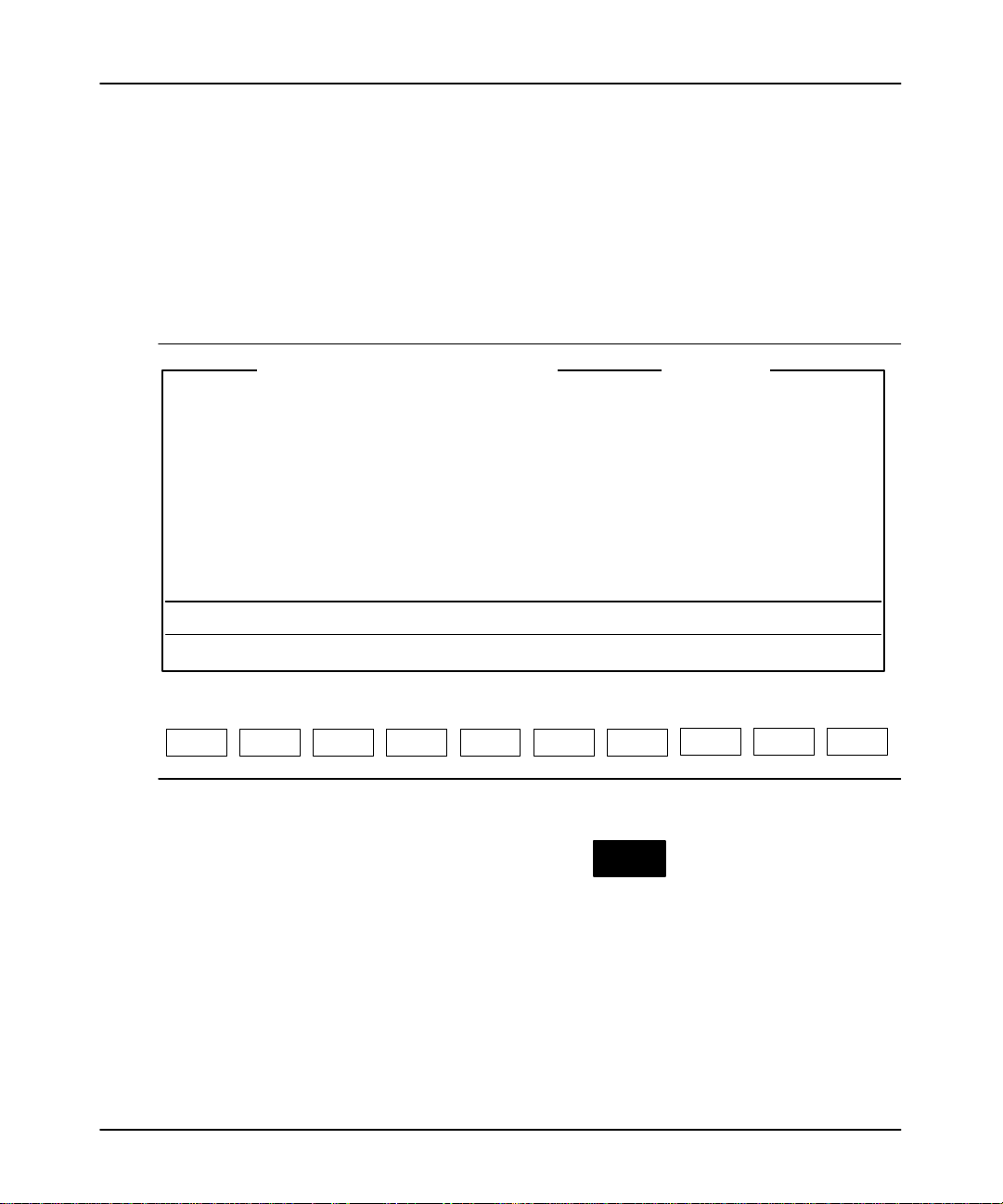
APS Screen Format
The APS screen is divided into three areas:
•
Display area
•
Message, prompt, data entry
• Main APS functions
and press
, and status lines
[ENTER].
The following figure indicates what appears in these areas.
2–3
Page 31

Advanced Programming Software User Manual
Preface
• Display Area: The five APS displays appear here - the APS menu, offline
program directory (shown here), offline monitor file, online program directory,
and online monitor file. Various option windows overlay these displays, de
pending on the function you are accessing. Also, the status data file and
other data files, force tables, and the memory map appear in this area.
PROGRAM DIRECTORY FOR PROCESSOR: 05TEST
FILE PROTECTED NAME TYPE SIZE (words)
0 system 217
1 reserved 0
2 ladder 9
3 ladder 4
Press a key, enter file number or file name
offline SLC 5/02 Series B File 05TEST
PROCSSR
FUNCTNS
F1 F2 F6 F7F4
SAVE CREATE
RETURN
TO MENU
F3
CHANGE
FILE
REPORTS
FILE
OPTIONS
MONITOR
FILE
F8
DATA
MONITOR
F9
MEMORY
MAP
F10
• Message, Prompt, Data Entry, and Status Lines
Message: Error codes/descriptions and information concerning
terminal or processor operation appear here.
Prompt: Indicates action you should take.
Data Entry: Information entered from the terminal keyboard
appears on this line.
Status: Status information concerning the processor and
program file appears on this line.
The Five Basic Menu Displays
This
section describes the five basic APS menu displays.
2–4
• Main Functions: APS functions appear here.
They are accessed by terminal keys F1 to F10.
You complete tasks by pressing the appropriate
function keys. In most cases, popup option
windows appear in the display area to facilitate
task completion. The main functions are
replaced with subfunctions related to options or
data entry.
Page 32

Main Menu Display
The following display is the main menu. This menu appears when you first enter
APS.
Navigating
Through the Software
SLC-500 ADVANCED PROGRAMMING SOFTWARE
Rockwell Software Incorporated, Copyright 1989-1995
9323 – PA2E
All Rights Reserved
This Software is licensed to: Your Name
Fri Nov 24, 1995 Current Offline File: DEFAULT 11:03:09 am
TERM Address: 0 Current Device: 1747-PIC (DH-485) PROC Address: 1
Press a function key
ONLINE ONLINE
CONFIG
OFFLINE
PRG/DOC
OFFLINE
CONFIG
WHO
SYSTEM
CONFIGR
OPTIONS
F1 F2 F6 F7F3 F4 F5
RELEASE 6.00
Your company name
00000000
FILE
PRINT
REPORTS
SYSTEM
UTILS
F9 F10F8
SYSTEM
This function key: Allows you to:
[F1] Online go online with the processor.
[F2] Online Configuration
change the online configuration of the terminal (port, terminal
address, processor address, and baud rate).
[F3] Offline Program/Document access the offline programming functions.
[F4] Offline Configuration
change the processor file in the terminal workspace or create
an archive processor file.
display node and network diagnostic windows, change the
[F5] WHO
programmer online configuration, and the network
configuration.
change the system configuration (highlight, color, printer
[F6] System Configuration
configuration, and system startup display). Also allows you to
specify the location of processor and documentation
directories for retrieval.
[F7] File Options
copy to or from a floppy. Also allows you to rename, copy, and
delete files.
EXIT
Continued
on next page
2–5
Page 33

Advanced Programming Software User Manual
Preface
This function key: Allows you to:
[F8] Print Reports print reports.
[F9] System Utilities
[F10] Exit System exit the software.
Offline Program Directory Display
The
following display appears when you press
PROGRAM DIRECTORY FOR PROCESSOR: 05TEST SINGLE STEP TEST: DISABLED
FILE PROTECTED NAME TYPE SIZE (words)
0 system 73
1 reserved 0
2 ladder 12
3 ladder 45
use the Prom Translator, which converts archive files to
hexadecimal format.
Also allows you to transfer a processor file between two APS
terminals or from an APS terminal to an HHT.
CONFIG
OFFLINE
OFFLINE
PRG/DOC
CONFIG
from the previous menu.
F3
2–6
Press a key, enter file number or file name
offline SLC 5/03 File 05TEST
PROCSSR
FUNCTNS
F1 F2 F6 F7F3 F4
SAVE CREATE
RETURN
TO MENU
CHANGE
FILE
REPORTS
FILE
OPTIONS
MONITOR
FILE
F8
DATA
MONITOR
F9
MEMORY
MAP
F10
This function key: Allows you to:
change the processor and I/O configuration;
add/delete/change a password or master password; change
[F1] Processor Functions
the processor file name; create/delete ladder program files;
name ladder program files; and clear the processor file from
the workspace.
[F2] Save save the processor file to disk.
[F4] Change File
replace the processor file with another processor file. Also
allows you to create an archive processor file.
[F6] Create Reports create reports.
[F7] File Options
rename, copy, and delete archive files. Also allows you to
copy a file to and from disk.
Page 34

Offline Monitor File Display
The
following display appears when you press
Navigating
CONFIG
MONITOR
OFFLINE
FILE
CONFIG
F8
Through the Software
from the previous menu.
IN
I:0.0
] [
0
EIGHT
T4:0
] [
DN
TON
TIMER ON DELAY
Timer EIGHT_SEC
Time Base 0.01
Preset 800
Accum 0
(EN)
(DN)
OUT
O:0.0
( )
0
END
Press a function key
(file 2, rung 0)
offline no forces EDITS: NONE File 05TEST
CONFIG
DISPLAY
F2
EXIT
F3
MULTI
POINT
F4
DOCUMNT
F5
SEARCH GENERAL
F6 F7 F8
UTILITY
DATA
MONITOR
FORCE
F9
EDIT
F10
This function key: Allows you to:
[F2] Configure Display
configure the ladder file display (display/suppress comments
and symbols).
access the multipoint list menu. (Available only for the
[F4] MultiPoint
SLC 5/03 OS302 and SLC 5/04 OS401 processors and the
MicroLogix 1000 controllers.)
[F5] Document
document ladder files (add/delete/edit comments and
symbols).
[F6] Search search, search and replace instructions/addresses.
[F7] General Utility
[F8] Data Monitor
[F9] Force
[F10] Edit
monitor/edit the status data file. Also allows you to clear minor
and major faults and clear the workspace memory.
monitor data file information and change the radix. You can
also edit data and move to the Force Monitor function.
force I/O from the force table. You can also access the Data
Monitor display and monitor forced I/O.
edit rungs and instructions, cut/copy/paste (advanced editing),
test edits, and use the quick edit feature.
2–7
Page 35

Advanced Programming Software User Manual
Preface
Online Program Directory Display
The following display appears when you enter the online mode by pressing
CONFIG
ONLINE
OFFLINE
CONFIG
PROGRAM DIRECTORY FOR PROCESSOR: 05TEST SINGLE STEP TEST: DISABLED
FILE PROTECTED NAME TYPE SIZE (words)
0 system 73
1 reserved 0
2 ladder 12
3 ladder 45
Press a key, enter file number or file name
REM RUN L532 Series C Rev 2 PROC Addr 2
PROCSSR
FUNCTNS
F1 F2 F6 F7F3 F4
SAVE
RESTORE
at the main menu.
F1
RETURN
TO MENU
CHANGE
LNK ADR
WHO
ACTIVE
F5
CREATE
REPORTS
FILE
OPTIONS
MONITOR
FILE
F8
DATA
MONITOR
F9
MEMORY
MAP
F10
2–8
The following function keys allow you complete tasks applying to the processor file
in the addressed processor
This function key: Allows you to:
[F1] Processor Functions
[F2] Save/Restore
[F4] Change Link Address
[F5] WHO Active
[F6] Create Reports specify the type of report you want to create.
[F7] File Options
.
change the processor mode. Copy a processor file stored in
an EEPROM to the processor memory.
save a processor file to disk or restore an archive file to the
processor memory.
communicate with a different node address on the DH485
network.
monitor the WHO Active window, change the network
configuration, monitor node and network diagnostic windows.
rename, copy, and delete archive files. You can also copy a
file to/from a floppy.
Page 36

Online Monitor File Display
The following display appears when you are online and you press
the previous menu.
Navigating
Through the Software
CONFIG
MONITOR
OFFLINE
FILE
CONFIG
from
F8
IN
I:0.0
] [
0
EIGHT
T4:0
] [
DN
TON
TIMER ON DELAY
Timer EIGHT_SEC
Time Base 0.01
Preset 800
Accum 0
(EN)
(DN)
OUT
O:0.0
( )
0
END
Press a function key
(file 2, rung 0)
REM RUN no forces EDITS: NONE PROC Addr 2
CHANGE
MODE
F1
CONFIG
DISPLAY
F2
EXIT
F3
MULTI
POINT
F4
DOCUMNT
F5
SEARCH GENERAL
F6 F7 F8
UTILITY
DATA
MONITOR
FORCE
F9
EDIT
F10
This function key: Allows you to:
[F1] Change Mode change processor mode.
[F2] Configure Display configure the ladder file display.
access the multipoint list menu. (Available only for the
[F4] MultiPoint
SLC 5/03 OS302 and SLC 5/04 OS401 processors and the
MicroLogix 1000 controllers.)
[F5] Document add rung and instruction comments to your ladder program.
[F6] Search search for instructions and addresses.
monitor and edit the status file; clear minor and major faults;
[F7] General Utility
clear the processor memory; and copy the processor file
to/from EEPROM and processor memory.
[F8] Data Monitor monitor data files, edit data, and change the radix.
[F9] Force force I/O from the force table and then monitor the forced I/O.
[F10] Edit edit the ladder program using the quick edit feature.
2–9
Page 37

Advanced Programming Software User Manual
Preface
Keys You Use
Within
APS you can use certain keys to access screen displays and then move the
cursor in those displays.
Hot Key Functions
Hot
key functions provide short cuts to display frequently used screens and
information.
This key combination
or function key:
[Alt-M]
alternate of
MEMORY
MAP
F1
[Alt-D]
alternate of
DATA
MONITOR
F8
[Alt-E]
alternate of
CONFIG
DISPLAY
F2
[Alt-S]
alternate of
SEARCH
F6
[Alt-T]
alternate of
DOCUMNT
F5
Allows you to:
access the Memory Map display. Functional at these displays:
Offline
Online
monitor file monitor file
edit
access the Data Monitor display. Functional at these displays:
Offline
Online
monitor file monitor file
edit
access the Configure Display menu choices. Functional at these
displays:
Offline Online
monitor file monitor file
edit force
force
access the Search menu choices. Functional at these displays:
Offline
Online
monitor file monitor file
edit force
force
access the Document menu choices. Functional at these displays:
Offline
Online
monitor file monitor file
edit
force
2–10
Page 38

Navigating
Through the Software
This key combination
or function key:
alternate of
[Alt-Shift-H] Disconnects the DF1 communication connection from the modem.
Control Key Functions
Control (CTRL) keys let you enter and edit the information you type on the
data/command line or in the data entry window on a screen. These keys perform the
same task on every screen in the software.
This key
combination:
[CTRL-A] toggle the insert mode between enable and disable.
[CTRL-B] move the cursor to the beginning of the line.
[CTRL-D] move the cursor one position to the left.
[CTRL-E] move the cursor to the end of the line.
[CTRL-F] move the cursor one position to the right.
[CTRL-H] move the cursor back one space (backspace).
[CTRL-J] delete the text from the cursor's current position to the end of the line.
[CTRL-M] add a carriage return.
[CTRL-R] recall the previous command you entered.
[CTRL-U] delete the text from the start of the line to the cursor's current position.
[CTRL-X] delete the entire line of text.
Allows you to:
[Alt-C]
Accesses Change Mode menu choices. Functional Online, at these
displays:
CHANGE
MODE
F1
online (program directory)
monitor file
force, monitor inputs, monitor outputs
configure display
data monitor
general utility, memory map, proc status
[Alt-U] Aborts changes, exits the function, and moves you to the previous
display. [ESC] exits the function and moves you to the previous
display, but does not abort changes.
[Alt-H] Accesses the online help text. This is available at any display.
Allows you to:
2–11
Page 39

Advanced Programming Software User Manual
Preface
CTRL Key Functions Only Available When Using Multiple Line Comment Editors
This key
combination:
[CTRL-J] delete the previous word.
[CTRL-N] move the cursor to the next word.
[CTRL-P] move the cursor to the previous word.
Additional Short Cut Keys
This key: Allows you to:
Enter/Return Key
Esc
Home
End
Pg Up
Pg Dn
Del
Allows you to:
enter data you've typed. It also functions as a Return key, to end
the current line and begin another when typing multiline
comments.
move to the previous display.
move left, right, up, and down in a ladder program, in a directory, or
in a data table.
move the cursor to the left power rail of rung 0 in a ladder program
or to the data at the upper left in a data file page, or to the top line
of a directory.
move the cursor to the last instruction of a ladder program or to the
data at the lower right in a data file page, or to the bottom line of a
directory.
move the cursor to the previous page in a directory or to the
previous page in a multipage data file.
move the cursor to the next page of a directory or to the next page
in a multipage data file.
move the cursor to the left in a line of typed characters, deleting
the characters as it moves.
move the cursor to the right in a line of typed characters, deleting
the characters as it moves.
delete typed characters on which the cursor is located.
2–12
Page 40

Configuring
Your System
3
Configuring Your System
This
chapter shows you how to:
•
select and save highlight options for ladder displays
•
select and save color options
• select and save the printer configuration
•
select and save the system startup display
•
define and save user
• monitor M0 and M1 files (SLC 5/03 and SLC 5/04 processors)
-preferred directory paths
3–1
Page 41

Advanced Programming Software User Manual
Preface
Configuration Options
The following pages show the factory default settings. If your system has been
previously configured, the displays may vary.
From the main menu, press
SYSTEM CONFIGURATION
F1 Editor Highlighting Style: REVERSE
F3 Color Selection: MONOCHROME
F4 Address
F5 Printer Configuration
F6 System Startup State: MAIN MENU
F7 Define Directory Paths
F8 Monitor M0/M1 Addresses: DISABLED
F9 Save Configuration
ESC exits/Alt-U aborts changes
Press a function key
CONFIG
OFFLINE
SYSTEM
CONFIGR
CONFIG
F6
to view the System Configuration display.
EDITOR
HILIGHT
F1 F6 F7F3 F5 F9
COLOR
SELECT
ADDRESS
F4
PRINTER
CONFIG
SYSTEM
STARTUP
DEFINE
DIR
M0/M1
MONITOR
F8
Editor Highlighting Style
Function key [F1], Editor Highlight toggles the editor highlighting style between
REVERSE and INTENSIFY. These two options are for monochrome and LCD
monitors only. They do not affect the color display monitors.
Reverse (Default Option – Preferred Option When Using an LCD Monitor)
• Cursor is shown as a flashing area (the instruction, rung location, or power rail
location alternately appears/disappears).
• T
rue instructions are shown as reversed screen areas.
• A true instruction at the cursor location is shown as a reversed screen area (true)
and flashing (cursor).
• Enabled forces are shown as On or Off in a reversed screen area.
3–2
SAVE
CONFIGR
Page 42

Intensify
Configuring
Your System
• Cursor is shown as a reversed screen area (located on an instruction, rung, or
power rail).
• True instructions are shown intensified (heavier line weight).
• A true instruction at the cursor location is shown diminished (true) in a reversed
screen area (cursor).
• Enabled forces are shown as an intensified “On” or “Off.”
Note If
you ar
e using a T47 terminal or another terminal having an LCD display
preferred option is REVERSE. With the INTENSIFY option, true instructions and
enabled for
intensified.
Color Selection
Function key [F3], Color Select toggles the Color Selection between
MONOCHROME and COLOR.
Monochrome (Default Option)
The display varies according to the type of monochrome or LCD monitor used. If
you are using a T45 or T47 terminal or another terminal having an LCD display, you
should use the MONOCHROME option. W
display are not easy to distinguish.
ces ar
e not easy to distinguish because they are diminished
ith the color option certain parts of the
, the
rather than
3–3
Page 43

Advanced Programming Software User Manual
Preface
Color
The following table describes the colors for the various APS functions and displays.
The functions and displays are described in chapter 2.
Monitor Display
Main Menu White Blue NA
Program Directories White Blue Black
Function Keys White Blue N/A
Function Key Displays Black Aqua Gray
Who Listen Red Gray NA
Who Active Red Gray Black
Message Line Yellow Black NA
Prompt Line Green Black NA
Data Entry Line White Black
Run Mode Green Black NA
Test Mode Blue Black NA
Program Mode White Black NA
Fault Codes Magenta Black NA
Status Line White Black NA
Ladder Logic Instructions White Black Red
Data Monitor White Black Red
True Instructions Green Black Red
Enabled Forces
Rung Comments Aqua Black NA
Address Comments Yellow Black NA
Instruction Comments Yellow Black NA
Instruction Symbols Magenta Black NA
Foreground
Color
Magenta
On" or Off"
Background
Color
Black Red
Cursor
White
Flashing
3–4
NA = Not Applicable
Page 44

Selectable Address Display
You
have the option to select the method used to reference the physical addressing
of bit (data) files. Bit files include outputs (O), inputs (I), and binary (B). For each
file type, you can select between two address displays:
• Word/Bit
• Sequential
Configuring
Your System
The following table shows the dif
Bit File Type Word/Bit Sequential Bit
Input
Output O0:0.1/1 O0:0/17
Binary
I1:2.0/10
I1:1.3/0
B3:5/10
B10:0/15
ferences between the two types of displays:
I1:2/10
I1:1/48
B3/90
B10/15
In addition you have the option of selecting short addressing for address display and
entry. Short addressing omits the file number and colon from the address. For
example, N13 is the short address of N7:13. See the
Instruction Set Refer
ence
Manual for more information.
Once you select the method(s) of display
, it is applied to the database editor
, create
reports function, and to the ladder display.
CONFIG
OFFLINE
1. From the System Configuration display
, press
ADDRESS
CONFIG
F4
. The function keys
toggle between Word/Bit and Sequential address display types. See the
following figure.
3–5
Page 45

Advanced Programming Software User Manual
Preface
SYSTEM CONFIGURATION
BIT ADDRESS DISPLAY
F2 Output File Address Display: Sequential
F3 Input File Address Display: Sequential
F4 Binary File Address Display: Word/Bit
F5 Short Address Display/Entry Disabled
F9 Save Configuration
ESC exits/Alt–U aborts changes
Press a function key
OUTPUT
FILE
F2
2. Select the address display for each file type. When you are finished, press
Note To
Sequential
3.
INPUT
FILE
F3 F9
CONFIG
OFFLINE
SAVE
CONFIG
CONFIG
F9
BINARY
FILE
F4
SHORT
ADDRESS
F5
. The message
NEW CONFIGURATION SAVED TO FILE
displayed.
enable short addr
essing, you must set
[F4] Binary File
.
Press
[ESC] and return to the System Configuration display.
SAVE
CONFIG
is
to
3–6
Page 46

Configuring Your Printer
This option allows you to designate the type and required configuration for your
printer.
Begin at the System Configuration display and press
1.
print options appear:
PRINTER CONFIGURATION
F1 Printer Type PARALLEL
F2 Port LPT1
F9 Save Configuration
F10 Printer Control
ESC exits/Alt–U aborts changes
Press a function key
PRINTER
TYPE
F1
PORT
NUMBER
F2
Configuring
CONFIG
OFFLINE
PRINTER
CONFIG
CONFIG
F5
Your System
. The following
SAVE
CONFIG
F9
PRINTER
CONTROL
F10
2. Select the printer type:
• The default configuration is PARALLEL port, so if you have a parallel
printer you do not need to change the printer type. Descriptions of the
function keys available follow. Use the keys to select the appropriate print
settings.
3–7
Page 47

Advanced Programming Software User Manual
Preface
Function Keys Description
[F1] Printer Type
[F2] Port Number Toggles between LPT1 and LPT2.
[F9] Save Configuration Saves your changes to file.
[F10] Printer Control
3. If you want to change to SERIAL port, press
configuration screen. Descriptions of the function keys available for the
SERIAL printer type follow.
Function Keys Description
[F1] Printer Type
[F2] Port Number Toggles between COM1 and COM2.
[F3] Baud Rate
[F4] Bits/Char Toggles between 7 and 8. The default is 8.
[F5] Stop Bits Toggles between 1 and 2. The default is 2.
[F6] Select Parity
[F7] Select Duplex
[F9] Save Configuration Saves your changes to file.
[F10] Printer Control
Toggles between Serial and Parallel printer
types. The default is a Parallel printer type.
Allows you to enter an initialization and
termination string. See page 3-9 for more
information. The following options are available:
[F1] Initial String - Allows you to enter a control
string of data for your current print request.
[F2] Termination String - Allows you to enter a
control string of data to reset the printer to its
previous setup mode.
CONFIG
OFFLINE
PRINTER
TYPE
CONFIG
Toggles between Serial and Parallel printer
types. The default is a Parallel printer type.
Toggles between 300, 600, 1200, 2400, 4800,
and 9600 baud. The default is 9600 baud.
Toggles between Even, Odd, and None. The
default is None.
Toggles between Half and Full. The default is
Half-duplex.
Allows you to enter an initialization and
termination string. See page 3-9 for more
information. The following options are available:
[F1] Initial String - Allows you to enter a control
string of data for your current print request.
[F2] Termination String - Allows you to enter a
control string of data to reset the printer to its
previous setup mode.
to access its printer
F1
3–8
4. Use the function keys to select the appropriate print settings.
Page 48

5. Save the control string by pressing
strings, press
Printer Control String Option
This option allows you to change the printer configuration for the current print
request. Y
characteristic of the typeface, such as bold or italic. Before using this option, we
recommend referring to the printer’s user manual for the correct printer control
sequences.
CONFIG
OFFLINE
SAVE
CONFIG
CONFIG
F9
CONFIG
OFFLINE
SAVE
TO FILE
TO FILE
CONFIG
. Once you have entered both
F9
, then [ENTER] or [ESC].
Configuring
Your System
ou can change the printer to condensed mode, the typeface, and the
We recommend using the initial string and termination string together
. This ensures
that the printer is reset to its previous setup mode for the next print request. Enter
the initial control string data first. It should not exceed 1 line of 160 printable
characters.
Control String Entry Priorities:
1. Enter the printable characters (hexadecimal values 20–7E).
2. Enter the control character (hexadecimal values 00–1F) by preceding it with the
control character, “^”. For example, hexadecimal value 12 (form feed) can be
entered as ^L.
3. Enter any character (hexadecimal values 00–FF) by preceding it with a
backslash, “\”. For example, <escape> can be entered as \027.
4. Enter any character (hexadecimal values 00–FF) by preceding it with an “x”
before the one or two hexadecimal digit string. For example, a vertical tab can
be entered as \x0B.
5. A “\” character followed by any non–numeric character is interpreted as that
character. For example, “\A” is interpreted as an “A”.
3–9
Page 49

Advanced Programming Software User Manual
Preface
Configuring Your System Startup State
This
function allows you to select the display that appears at system startup.
1.
At the main menu display press
SYSTEM CONFIGURATION
F1 Editor Highlighting Style: REVERSE
F3 Color Selection: COLOR
F4 Bit Address Display:
F5 Printer Configuration
F6 System Startup State: MAIN MENU
F7 Define Directory Paths
F8 Monitor M0/M1 Addresses: DISABLED
F9 Save Configuration
ESC exits/Alt–U aborts changes
Press a function key
CONFIG
OFFLINE
SYSTEM
CONFIGR
CONFIG
F6
. The following display appears:
EDITOR
HILIGHT
F1 F6 F7F3 F5 F9
COLOR
SELECT
BIT
DISPLAY
F4
PRINTER
CONFIG
SYSTEM
STARTUP
DEFINE
DIR
M0/M1
MONITOR
F8
Function key [F6], System Startup scrolls through the following selections:
•
Main Menu
•
WHO Menu
•
Online Menu
• Offline Menu
• Offline Config Menu
• Multi-point Menu (Available for SLC 5/03 OS302 and SLC 5/04 OS401
processors only
2. Save the new configuration for future sessions by pressing
message:
NEW CONFIGURATION SAVED TO FILE
.)
CONFIG
OFFLINE
CONFIGR
CONFIG
is displayed.
SAVE
CONFIGR
SAVE
F9
. The
3–10
Page 50

Defining Your Directory Paths
1. At
the System Configuration display press
window appears.
USER DIRECTORIES
F2 Temporary Files: C:\IPDS\TEMP
F4 Processor Memory, Comments and Symbols: C:\IPDS\ARCH\SLC500
F5 Documentation Reports: C:\IPDS\LIS\SLC500
F6 Exported Files: C:\IPDS\TEXT\SLC500
F7 User Configuration: C:\IPDS\ATTACH\SLC500
F9 Save Configuration
F10 Set Directories to Default
ESC exits/Alt–U aborts changes
Press a function key
CONFIG
OFFLINE
DEFINE
DIR
CONFIG
F7
Configuring
Your System
. The user directory
TEMP
DIR
F1
PROCESS
DIR
DOCUMEN
DIR
EXPORT
DIR
F
CONFIG
DIR
F7F4 F5
SAVE
CONFIG
F9 F10
DEFAULT
DIRS
2. Using the available function keys, create new directory names according to your
needs. The following keys are also active at these displays:
Key Description
Edit keys
Left and right arrows, backspace, and [CTRL-J] (deletes to
end of line).
Ins Toggles between insert and overstrike mode.
[ENTER] or [ESC] Closes the window and saves any changes made.
[ALT-U] Closes the window and cancels any changes made.
CONFIG
OFFLINE
Function
key
TEMP
DIR
CONFIG
F2
brings up the following window, displaying the default
directory name for temporary files.
TEMPORARY FILES
C:\IPDS\TEMP
ESC exits/Alt–U aborts changes
[Overstrike]
3–11
Page 51

Advanced Programming Software User Manual
Preface
CONFIG
OFFLINE
Function
key
PROCESS
CONFIG
directory name for processor memory
PROCESSOR MEMORY, COMMENTS, AND SYMBOLS
C:\IPDS\ARCH\SLC500
ESC exits/Alt–U aborts changes
CONFIG
OFFLINE
Function
key
DOCUMEN
CONFIG
directory name for documentation reports.
DOCUMENTATION REPORTS
C:\IPDS\LIS\SLC500
ESC exits/Alt–U aborts changes
brings up the following window, displaying the default
DIR
F4
, comments, and symbols.
[Overstrike]
brings up the following window, displaying the default
DIR
F5
[Overstrike]
3–12
CONFIG
OFFLINE
Function
key
EXPORT
DIR
CONFIG
F6
brings up the following window, displaying the default
directory name for export files.
EXPORTED FILES
C:\IPDS\TEXT\SLC500
ESC exits/Alt–U aborts changes
CONFIG
OFFLINE
Function
key
CONFIG
DIR
CONFIG
F7
brings up the following window, displaying the default
directory name for user configuration.
USER CONFIGURATION
C:\IPDS\ATTACH\SLC500
ESC exits/Alt–U aborts changes
[Overstrike]
[Overstrike]
Page 52

If the directory does not exist you are prompted to either continue and create a
directory or abort the procedure.
The error message ERROR CREATING DIRECTORY appears if the name of a
directory is not supported by DOS. The maximum length of a path name is 65
characters.
After you have entered a new directory name,
configuration for future sessions. Press [ENTER] or [ESC] to return to the
System Configuration display.
CONFIG
OFFLINE
Use function key
DEFAULT
DIRS
CONFIG
if you selected a custom directory and wish to change
F10
it back to the default directory.
Determining Your Monitoring Requirements
(SLC 5/03 and SLC 5/04 Processors)
CONFIG
OFFLINE
SAVE
CONFIG
CONFIG
F9
Configuring
saves the
Your System
The M0/M1 Monitoring option is available for SLC 5/03 and SLC 5/04 processors.
These files reside in specialty I/O modules only
the processor memory. The application of these files depends on the function of the
particular specialty I/O module. For some modules, the M0 file is regarded as a
module output file and the M1 file is regarded as a module input file. Refer to the
screen display on page
Function key
Disabled. If monitoring of M0 and M1 files is enabled and you are currently online
with a SLC 5/03 or SLC 5/04 processor
• Data Table Monitor
• Ladder Monitor
• Ladder Listing Report
• Data Table Report
Note Additionally,
This is determined by the number of M0/M1 addr
single APS monitor scr
. There is no image for these files in
3–10.
CONFIG
OFFLINE
M0/M1
MONITOR
CONFIG
toggles between Enable and Disabled. The default is
F8
, monitoring is enabled in these areas:
when this option is enabled, scan time can be increased significantly
esses that can be displayed on a
een.
3–13
.
Page 53

Advanced Programming Software User Manual
Preface
Saving Your Configuration
Once
you have your system configured, you must save the changes. Use one of the
following methods to save your system configuration.
CONFIG
OFFLINE
•
Press
and future sessions.
•
Press
SAVE
CONFIGR
CONFIG
, then [ENTER] or [ESC] to save the configuration for this
F9
[ENTER] or [ESC] to enforce your selection for this session only.
Pressing
[ALT-U] aborts any change you make and returns you to the APS main
menu.
File Extensions Used by APS and APSIE
These file extensions are preceded by an 8-character archive filename specified by
the user when creating the processor file. The archive filename must follow the
rules and restrictions pertaining to DOS filenames.
File Type APS APSIE Default Directory
V1.00
V1.01
V2.00
V2.01
V3.00 V3.20
V1.02
V1.04
APS User Preference
File
APS Cross Reference
Report
APS Data Table Report .DTR .DTR .DTR .DTR \ipds\lis\slc500
APS UVPROM
Translator Files
APS Processor
Configuration Report
APS Error View File .ERR .ERR .ERR .ERR \ipds\lis\slc500
APS Ladder File Names .NAM .NAM .NAM .NAM \ipds\arch\slc500
APS User Directory
Configuration
APS Overlay Files .OVL .OVL \ipds\attach\slc500
.P10 .P20 .P30 .P32
.XRF .XRF .XRF .XRF .XRF \ipds\lis\slc500
.HEX .HEX .HEX .HEX \ipds\arch\slc500
.PCR .PCR .PCR .PCR \ipds\lis\slc500
.CFG .CFG .CFG \ipds\attach\slc500
V4.0
V5.0
V6.0
.P40
.P50
.P60
.PIE \ipds\attach\slc500
3–14
Page 54

File Type Default DirectoryAPSIEAPS
APS Rung Comment,
Instruction Comment,
Address Comment, and
Symbol Files.
Note: Do not change or
delete these files.
APS Cross Reference
Files
Note: Do not change or
delete these files.
APS Program Listing
Report
APS Message and
Prompt File
APS Function Key
Menu Text
V1.00
V1.01
V1.02
V2.00
V2.01
V3.20V3.00
V1.04
.AC$
.B0$
.B1$
.IX$
.LX$
.OP$
.PC$
.XD$
.XO$
.B2$
.LIS \ipds\lis\slc500
.DT0 .DT0 .DT0 .DT0 .DT0 \ipds\attach\slc500
.DT1 .DT1 .DT1 \ipds\attach\slc500
V4.0
V5.0
V6.0
APS Windows Text .DT3
APS Help Files
(APSHELP.XXX for
Version 4.0 and
APHELP.xxx for
.DAT
.OFF
Versions 5.0 and 6.0)
APS Archive File and
Data Tables
APS/APSIE Executable
and Link Layer Files
APSIE Processor
Memory Text File
APSIE Documentation
Text
APSIE User Directory
Configuration
APSIE Summary Log
File
.ACH \ipds\arch\slc500
.EXE .EXE \ipds\attach\slc500
.SLC \ipds\text\slc500
.TXT \ipds\text\slc500
.CFG \ipds\attach\slc500
.LOG \ipds\arch\slc500
Configuring
Your System
\ipds\arch\slc500
\ipds\arch\slc500
\ipds\attach\slc500
\ipds\attach\slc500
3–15
Page 55

Ladder Logic Program Basics
4
Ladder Logic Program Basics
This chapter discusses the basic operation of ladder logic programs. T
• understanding ladder logic programs
• types of ladder logic connections
• application example – 4-rung ladder logic program
For a more detailed introduction to ladder logic programming, refer to the APS
Quick Start for New Users
. This guide is intended for the first time user.
opics include:
4–1
Page 56

Advanced Programming Software User Manual
Preface
Understanding Ladder Logic Programs
Ladder logic is a graphical programming language based on electrical relay
diagrams. Instead of having electrical rung continuity, ladder logic is looking for
logical rung continuity. A ladder logic diagram identifies each of the elements in an
electromechanical circuit and represents them graphically
how your control circuit operates before you actually start the physical operation of
your system.
input instructions output instruction
I
] [
I
]/[
0
1
The ladder logic program you enter into the controller’s memory contains bit (relay
logic) instructions representing external input and output devices. It also contains
other instructions, as described in the Instruction Set Refer
As your program is scanned during controller operation, the changing on/off state of
the external inputs is applied to your program, energizing and de-energizing external
outputs according to the ladder logic you have programmed.
( )
O
1
. This allows you to see
ence Manual.
4–2
To illustrate how ladder logic programming works, we chose to use bit (relay logic)
instructions, since they are probably the easiest to understand. The three
instructions discussed in this section are:
Examine if Closed (XIC)
] [
]/[
( )
Analogous to the normally open relay contact. For this instruction, we ask the
processor to Examine if (the contact is) Closed."
Examine if Open (XIO)
Analogous to the normally closed relay contact. For this instruction, we ask the
processor to Examine if (the contact is) Open."
Output Energize (OTE)
Analogous to the relay coil. The processor makes this instruction true (analogous
to energizing a coil) when there is a path of true XIC and XIO instructions in the
rung.
Keep in mind that operation of these instructions is similar but not equivalent to that
of relay contacts and coils. In fact, a knowledge of relay control techniques is not a
prerequisite for programming with ladder logic.
Page 57

Example 1-Rung Ladder Logic Program
A ladder logic program consists of individual rungs, each containing at least one
output instruction and one or more input instructions. The ladder rung that follows
has two input instructions and an output instruction. An output instruction always
appears at the right, next to the right power rail. Input instructions always appear to
the left of the output instruction.
Input Instructions Output Instruction
XIC
XIO OTE
Ladder Logic Program Basics
B3
] [
XIC = Examine if Closed
XIO = Examine if Open
OTE = Output Energize
A simple rung, using relay logic instructions
Note
that each instruction in the diagram above has an address. This address
10
B3
]/[
11
B3
( )
12
Address B3/10
Address B3/11
Address B3/12
identifies a location in the processor’s data files, where the on/off state of the bit is
stored. Addresses of the above instructions indicate Bit data file 3 (B3), bits 10, 1
and 12:
15 14 13 12 11 10 9 8 7 6 5 4 3 2 1 0
0 0 0 1 0 1 0 0 0 0 0 0 0 0 0 0
Bit Data File 3
OTE XICXIO
Bit Status
In the preceding diagram, we indicated that bit 10 is logic 1 (On), bit 1
Element 0
1 is logic 0
(Off), and bit 12 is logic 1 (On). These logic states indicate whether an instruction
is true or false, as pointed out in the following table.
1,
4–3
Page 58

Advanced Programming Software User Manual
Preface
The status of the instruction is
From
instruction, XIO instruction, and OTE instruction of our rung are all true. The
true/false state of instructions is the basis of controller operation, as indicated in the
following sections.
Logical Continuity
During controller operation, the processor determines the on/off state of the bits in
the data files, evaluates the rung logic, and changes the state of the outputs
according to the logical continuity of rungs. More specifically
up the conditions under which the processor will make an output instruction true or
false. These conditions are:
• When the processor finds a continuous path of true input instructions in a rung,
•
If the data table
bit is
Logic 0 False True False
Logic 1 True False True
XIC
Examine if Closed
] [
the above table, we see that status bits 10, 1
XIO
Examine if Open
]/[
1, and 12 indicate that the XIC
OTE
Output Energize
( )
, input instructions set
the OTE output instruction will become (or remain) true. W
e then say that
“rung conditions are true.”
When the processor does
not find a continuous path of true input instructions in
a rung, the OTE output instruction will become (or remain) false. W
that “rung conditions are false.”
e then say
4–4
The figure below shows the on/off state of output B3/12 as determined by the
changing states of the inputs in the rung.
Input Instructions Output Instructions
XIC XIO OTE
B3
10
B3
11
B3
12
Page 59

Ladder Logic Program Basics
Inputs Output
Time XIC XIO OTE XIC XIO OTE
t1(initial) False True False 0 0 0
t
2
t
3
t
4
True
True False Goes False 1 1 0
False False Remains False 0 1 0
True Goes True 1 0 1
Types of Ladder Logic Connections
In a ladder logic diagram each of the input devices are represented in series or
parallel logic combinations across the rung of the ladder. The last element on the
rung is the output that receives the action as a result of the conditional state of the
inputs on the rung.
Series Logic
Bit Status
In the previous section on logical continuity
, you have seen examples of series
(AND) logic. This means that when all input conditions in the path are true,
energize the output.
a
b
In the above example, if A and B are true, ener
c
gize C.
4–5
Page 60

Advanced Programming Software User Manual
Preface
Parallel Logic
Another form of logical continuity is parallel (OR) logic. This means that when one
or another path of logic is true, energize the output.
Example — Parallel Inputs
Input Branching
a
b
In the above example, if A or B is true, ener
c
gize C.
Use branching to form parallel logic in your user program. Branches can be
established at both input and output portions of a rung. The upper limit on the
number of levels which can be programmed in a branch structure is 75. The
maximum number of simple instructions per rung is 128. (The maximum number
decreases if the rung contains instructions with many parameters, or if complex
addressing is used.)
Use an input branch in your application program to allow more than one
combination of input conditions to form parallel branches (OR-logic conditions). If
at least one of these parallel branches forms a true logic path, the rung logic is
enabled. If none of the parallel branches forms a true logic path, rung logic is not
enabled and the output instruction logic will not be true. Output is not energized.
Example — Parallel Input Branching
a
c
In the above example, either A and
4–6
b
B,
or C provides a true logical path.
d
Page 61

Output Branching
You can program parallel outputs on a rung to allow a true logic path to control
multiple outputs. When there is a true logic path, all parallel outputs become true.
Example — Parallel Output Branching
Ladder Logic Program Basics
a
b
In the above example, either A or B provides a true logical path to all three output
instructions.
Additional input logic instructions (conditions) can be programmed in the output
branches to further condition control of the outputs. When there is a true logic path,
including extra input conditions on an output branch, that branch becomes true.
Example — Parallel Output Branching with Conditions
a
b
de
c
d
e
c
In the above example, either A and D or
to E.
B
and D provide a true logic path
4–7
Page 62

Advanced Programming Software User Manual
Preface
Branching Combinations and Limitations
Use branching to avoid redundant instructions, speed-up processor evaluation, and
provide more efficient programming.
APS allows branching combinations to be programmed in the fixed, SLC 5/01, SLC
5/02, SLC 5/03, and SLC 5/04 processors, and the MicroLogix 1000 controllers.
(Note that the Hand-Held Terminal (HHT) does not allow nested input and output
branches to be programmed in a fixed or SLC 5/01 processor.)
Extended Branching Versus Nested Branching
Using extended branches rather than nested branches is more ef
ficient and speeds up
processor evaluation. Both of the examples shown below accomplish the same
result; however, the extended branching example is evaluated approximately 1 ms
faster than the nested branching example.
Extended Branching
Nested Branching
4–8
Page 63

Branching Limitations
Ladder Logic Program Basics
You are limited to four nested branches per rung; however
have up to 75 extended branches, as shown below
Nest 1, Extension 1
Nest 1, Extension 2
Nest 1, Extension 3
.
.
.
Nest 1, Extension 75
Nest 2, Extension 1
Nest 2, Extension 2
Nest 2, Extension 3
.
.
.
Nest 2, Extension 75
Nest 3, Extension 1
Nest 3, Extension 2
Nest 3, Extension 3
.
.
.
Nest 3, Extension 75
Nest 4, Extension 1
Nest 4, Extension 2
Nest 4, Extension 3
.
.
.
Nest 4, Extension 75
.
, each nested branch can
4–9
Page 64

Advanced Programming Software User Manual
Preface
Connecting Blocks
Blocks
of input and output instructions can be connected in series and parallel as
well.
Example – Series Block Connection
a
b
In the above example, two blocks of information are connected in series. Either A
B,
and
C
or
or D provides a true logical path.
Example – Parallel Block Connection
a
c
b
d
In the above example, two blocks of information are connected in parallel. Either A
and
B, or C
and D provides a true logical path.
c
d
e
e
4–10
Page 65

Ladder Logic Program Basics
Application Example – 4-Rung Ladder Logic Program
The following 4-rung ladder logic program uses the same 3 bit locations as our
simple 1-rung diagram. It also uses an external input bit address and an external
output bit address. Note that individual bits are addressed repeatedly
1 is addressed with an XIC instruction in rungs 1 and 4, and it is addressed with
B3/1
both an XIC and an OTE instruction in rung 2.
During normal controller operation, the processor checks the state of the input data
file bits, then executes the program instructions individually, rung by rung, from the
beginning to the end of the program; as it does, it updates the data file bits and
energizes the appropriate output data file bits accordingly.
When the XIC instruction I:0/1 goes true (because an external momentary push
button closes):
•
Rung 1 is evaluated as false, because XIC instruction B3/1
•
Rung 2 is evaluated as true. XIC B3/1
maintain continuity in the rung.
•
Rung 3 is evaluated as true.
•
Rung 4 is evaluated as true because XIC B3/1
device represented by OTE O:0/2 is energized.
1 in the branch of this rung goes true to
1 has gone true. The external
. For example,
1 is false at this time.
Use the following program to achieve the maintained contact action of an On-Off
toggle switch using a momentary contact push button. Press for On. Press again for
Off.
The first time you press the push button (represented by address I:0/1), instruction
1 is latched, ener
B3/1
button, instruction B3/12 unlatches instruction B3/11, de-energizing output O:0/2.
Instruction B3/10 prevents interaction between instructions B3/12 and B3/11.
gizing output O:0/2. The second time you press the push
4–11
Page 66

Advanced Programming Software User Manual
Preface
1
2
3
4
Rung
1
2
3
4
I:0
] [
I:0
] [
B3
] [
I:0
B3
1
1
11
] [
] [
I:0/1
] [
] [
] [
1
11
B3
]/[
B3
]/[
B3
10
10
B3/10 B3/12 O:0/2B3/11
]/[
]/[
( )
] [
11
B3
]/[
12
( )
Status
] [
] [
B3
( )
B3
( )
B3
( )
O:0
( )
Bit
12
11
10
2
] [
( )
]/[
( )
4–12
Previously,
we indicated that the processor executes instructions individually
, rung
by rung, from the beginning to the end of the program. This is called a program
scan and is repeated many times a second. The figure on the next page indicates in
greater detail what happens during individual scans when an external input device
(represented by I:0/1) is operated.
When the state of a bit changes during the program scan, the ef
fects this may have
in earlier rungs of the program are not accounted for until the next scan. To point
this out, we have shown successive scans (1000 and 1001, 2000 and 2001, etc.).
Page 67

Ladder Logic Program Basics
I:0
I:0
B3
The
diagram above is the same one that appears on the
preceding page. This diagram is also represented below
with each instruction replaced with a T or F
initial T
rue/False status of the instruction.
The table at the right indicates how the instructions are
executed when XIC instruction I:0/1 changes state. (I:0/1
represents an external momentary contact push button.)
B3
] [
] [
] [
I:0
B3
]/[
1
1
11
] [
] [
10
B3
]/[
10
1
11
FTFF
FTTF
F
F F
F F
B3
B3
] [
]/[
11
12
B3
( )
12
B3
( )
11
B3
( )
10
O:0
( )
2
, indicating the
XIC
I:0/1
Goes
True
Goes
False
,
Goes
True
Goes
False
Instruction
T = true at time of execution
F = false at time of execution
Execution
Scan 1000 Scan 1001
TTFF
TTTT
F
T T
T T
Scan 2000 Scan 2001
FFTF
FFTT
T
F F
T T
Scan 3000 Scan 3001
TTTT
TTFF
T
T T
F F
Scan 4000 Scan 4001
FFFF
FFTF
F
F F
F F
TFTF
TFTT
T
T T
T T
FTTF
FTTT
T
F F
T T
TFFF
TFTF
F
T T
F F
FTFF
FTTF
F
F F
F F
4–13
Page 68

Creating and Configuring Processor Files
5
Creating and Configuring Processor
Files
This chapter discusses the related functions for creating and editing a processor file.
Those functions include:
•
processor functions
• deleting a processor file from the workspace
• archive file operations
5–1
Page 69

Advanced Programming Software User Manual
Preface
Processor Functions
This section shows you how to create an example processor file. The example file
is compatible with a modular controller consisting of:
•
Chassis 1746-A4 (chassis 1)
• Processor 1747-L532 (slot 0)
• Input Modules 1746-IA4 and 1746-IA8 (slots 1 and 2)
• Output Module 1746-OA8 (slot 3)
The processor file name chosen for this example is EXAMPLE.
Creating Processor Files
1. Begin
at the main menu and press
2. At the prompt, type: EXAMPLE. EXAMPLE
entry line. (File names can be a maximum of 8 characters in length.)
If you press [ESC] at this time, the error message: FILENAME MUST BE
SPECIFIED
is displayed. If you press
appears.
PROCESSOR
BUL. 1761 Micrologix 1000
1747-L511 5/01 CPU – 1K USER MEMORY
1747-L514 5/01 CPU – 4K USER MEMORY
1747-L524 5/02 CPU – 4K USER MEMORY
1747-L532 5/03 CPU –12K USER MEMORY
1747-L541 5/04 CPU –12K USER MEMORY
CREATE PROCESSOR FILE
NAME: EXAMPLE
F2 Processor: Bul. 1761 MicroLogix 1000
ESC exits/Alt–U aborts changes
Press a Function Key or Enter File Name
SELECT
PROC
F2
INPUTS OUTPUTS
CONFIGR
I/O
F5
CONFIG
OFFLINE
CONFIG
ADJUST
FILTERS
F6
OFFLINE
CONFIG
F4
[ALT–U]
CONFIG
OFFLINE
, then
CREATE
FILE
CONFIG
F6
.
appears on the data/command
, the previous display
SAVE &
EXIT
F8
5–2
Page 70

Creating and Configuring Processor Files
3. Press [ENTER]. This places the processor file name in the lower window.
4. The Create Processor File window lists the default processor, Bul. 1761. For
our example we are using the 1747-L532 processor. Cursor down to highlight
it. (If you are using a different processor
appropriate processor in the upper option window.) Press
, use the cursor keys to locate the
CONFIG
OFFLINE
SELECT
PROC
CONFIG
.
F2
PROCESSOR INPUTS OUTPUTS
1747-OS300 SERIES A
1747-OS301 SERIES A
1747-OS302 SERIES A
CREATE PROCESSOR FILE
NAME: EXAMPLE
F2 Processor: 1747-L532 5/03 CPU –12K USER MEMORY
ESC exits/Alt–U aborts changes
Press a Function key, ENTER to Select Processor, ESC to exit, or Alt–U to abort
PAGE
UP
F1
Note If
If you select either an SLC 5/03 or SLC 5/04 processor
, a display like the
following appears:
OPERATING SYSTEM
PAGE
DOWN
F2
Check the label on your processor to verify which operating system you are
using. Highlight the correct operating system and press [ENTER]. Note that
the status line does not reflect the current operating system.
CONFIG
OFFLINE
you ar
e using a Micr
step 10 on page
oLogix 1000 controller
5–7.
, pr
ess
SAVE &
EXIT
CONFIG
F8
and then move on to
5–3
Page 71

Advanced Programming Software User Manual
Preface
CONFIG
OFFLINE
5.
Press
I/O CONFIGURATION FOR:EXAMPLE
RACK 1 = 1746-A4 4-SLOT Backplane
RACK 2 = NOT INSTALLED
RACK 3 = NOT INSTALLED
SLOT CATALOG # CARD DESCRIPTION
*0 1747-L532 5/03 CPU -12K USER MEMORY
*1
*2
*3
4
5
6
7
8
ESC exits
Press a function key
CONFIGR
I/O
CONFIG
F5
. The following display appears:
READ
CONFIG
F1 F2
ONLINE
CONFIG
The
display title is
MODIFY
RACKS
MODIFY
SLOT
DELETE
SLOT
F6 F7F4 F5
UNDEL
SLOT
I/O CONFIGURATION FOR:EXAMPLE.
EXIT
F8
SPIO
CONFIG
F9
The chassis
selection is Rack 1 = 1746-A4, 4-slot. Racks 2 and 3 are not installed.
Slot 0 lists the processor
, 1747-L532. Slots 1, 2, and 3 must be specified. (An
asterisk indicates the slot is available.)
SLC 5/03 and SLC 5/04 Processors – Reading I/O Configuration
The read I/O configuration function allows the programming device to read the
actual processor I/O configuration. Use function keys [F1], Read Configuration
and [F2], Online Configuration to perform this function.
When you press [F1], Read Configuration, APS attempts to attach to the
processor node specified in the current online configuration. If the attempt to
attach to the processor node fails, the message:
OF COMMUNICATIONS
is displayed.
MESSAGE TIMEOUT–LOSS
If the current processor type is not an SLC 5/03 or SLC 5/04, as specified in the
online configuration, the message: SELECTED PROCESSOR DOES NOT
SUPPORT THIS FEATURE, CHECK ONLINE CONFIGURATION
displayed. To check the online configuration, press [F2], Online Configuration.
If necessary
, change the processor node address and press [F9], Save To File.
is
5–4
Page 72

Creating and Configuring Processor Files
Note that the currently selected processor type in the I/O configuration does not
have to be set to an SLC 5/03 or SLC 5/04 processor for the read I/O
configuration function to be performed. Only the current processor type as
specified by the processor node address in the current online configuration must
be an SLC 5/03 or SLC 5/04 processor.
The status line is updated and the updated processor I/O configuration is
displayed on the screen when the following events occur:
• the current communication driver is successfully activated
• the online configuration specifies an SLC 5/03 or SLC 5/04 processor
•
APS successfully attaches to the processor
If the read of the auto configuration from the processor is successful, the
information is stored in the I/O configuration for the current archive file.
If the attempt to read the auto configuration file from the processor
the current online configuration, fails the message: ERROR ACCESSING
PROCESSOR I/O CONFIGURATION FILE
G Files: If one or more slots are detected as having a G File associated with it
when a read configuration is performed, the message: G FILES NEED TO
BE INITIALIZED
is displayed. To initialize these files, you must first set the
G file size and then modify the G file. Refer to page 5–8 for the screen display
that allows you to access the G file information.
CONFIG
OFFLINE
6.
Press
I/O MODULE SELECTION FOR SLOT: 1
CATALOG CARD DESCRIPTION
1746-I*8 8 - Any 8 point Discrete Input Module
1746-I*16 16 - Any 16 point Discrete Input Module
1746-I*32 32 - Any 32 point Discrete Input Module
1746-O*8 8 - Any 8 point Discrete Output Module
1746-O*16 16 - Any 16 point Discrete Output Module
1746-O*32 32 - Any 32 point Discrete Output Module
1746-IA4 4 - Input 100/120 VAC
1746-IA8 8 - Input 100/120 VAC
1746-IA16 16 - Input 100/120 VAC
ESC exits
Press ENTER to select I/O Module
Enter Module ID Code >
MODIFY
SLOT
CONFIG
F5
. This brings up the I/O module selection for slot 1.
, specified by
is displayed.
SELECT
MODULE
F2
5–5
Page 73

Advanced Programming Software User Manual
Preface
SLC 5/02, SLC 5/03, and SLC 5/04 processors – You have the option of
configuring generic I/O modules having 8, 16, or 32 discrete I/O. For example,
if you select 1746-I*8, any 8-point discrete input module may be used.
7. Select a module for the indicated slot number by positioning the cursor on the
desired module and pressing either
already correctly positioned in this case. The I/O configuration display
reappears.
8. Repeat the procedure until you have configured all of the required I/O.
9. Once you have configured all of your I/O press
CONFIG
OFFLINE
SAVE &
EXIT
CONFIG
. The following display appears:
F8
CONFIG
OFFLINE
SELECT
MODULE
CONFIG
C:\IPDS\ARCH\SLC500
Name Size Date
CONVEYOR 8847 08-18-95
DRILL1 9392 09-12-95
EXAMPLE 929 10-07-95
MIXER 10221 10-15-94
ONOFF 9334 08-04-95
PAINTGUN 9261 07-19-94
RPMCALC 8704 04-27-94
SEQUENCE 8684 10-03-95
STOP_GO 8586 09-28-94
TOGGLE 8695 07-19-94
or [ENTER]. The cursor is
F2
CONFIG
OFFLINE
EXIT
CONFIG
or [ESC], then
F8
NEW ARCHIVE FILE CREATED
Press a Function Key or Enter File Name
OFFLINE
PRG/DOC
The
message line indicates
EXAMPLE, along with the size and date appear in the right-hand window. This
file is now in the terminal workspace.
5–6
CREATE
FILE
F6 F7F1
DEFINE
DIR
SAVE
TO FILE
F9
NEW ARCHIVE FILE CREATED. The name
Page 74

Creating and Configuring Processor Files
CONFIG
OFFLINE
10. If you wish to change the processor type or I/O configuration, press
OFFLINE
PRG/DOC
CONFIG
F1
The program directory of the offline processor file is displayed.
PROGRAM DIRECTORY FOR PROCESSOR: EXAMPLE
FILE PROTECTED NAME TYPE SIZE (words)
0 system *
1 reserved *
2 No ladder *
Press a key, enter file number or file name
offline SLC 5/03 File EXAMPLE
PROCSSR
FUNCTNS
SAVE CREATE
RETURN
TO MENU
F1 F2 F6 F7F3 F4
The
status line indicates that you are of
CHANGE
FILE
REPORTS
FILE
OPTIONS
MONITOR
FILE
F8
fline, the configured processor is an
DATA
MONITOR
F9
MEMORY
SLC 5/03, and the processor file is EXAMPLE.
.
MAP
F10
CONFIG
OFFLINE
PROCSSR
11.
Press
FUNCTNS
CONFIG
to modify a processor file. The following display appears:
F1
Press a key, enter file number or file name
offline SLC 5/03 File EXAMPLE
CHANGE
PROCSSR
CHANGE
PASSWORD
CHANGE
PR. NAME
F1 F2 F6 F7F3 F4
CHANGE
FL. NAME
CLEAR
MEMORY
F5
CREATE
FILE
DELETE
FILE
MONITOR
FILE
F8
DATA
MONITOR
F9
FILE
PROTECT
F10
You can now change the processor type or I/O configuration.
If you select an incompatible configuration, the message I/O
CONFIGURATION DOES NOT MATCH PROGRAM appears. After you make
a compatible selection, return to the processor functions menu.
5–7
Page 75

Advanced Programming Software User Manual
Preface
Configuring Speciality I/O Modules
When you use a specialty I/O module, you must indicate the type of module to APS.
The configuration menu provides a list of available modules from which to select.
Each module is pre-configured, so after selecting the module from the list you have
the option of viewing its configuration by pressing [F9], SPIO Configuration.
Alteration of the fields is not recommended since these fields are pre-configured.
However, if you select a module not listed, you may be required to alter some of the
fields. Refer to your specialty I/O module user manual for more information
regarding the required parameters.
To configure a specialty I/O module not listed, do the following:
1. At the I/O Configuration menu (refer to page 5–4
the [down arrow] key or the [END]
select
OTHER from the list.
CONFIG
OFFLINE
), press
key
, go to the end of the menu and
MODIFY
SLOT
CONFIG
F5
. Using
2. Refer to your specialty I/O module user manual and enter the module’
at the prompt. For example, type: 12705. This is the ID code for the
1746-HSCE module. Press [ENTER].
CONFIG
SPIO
3.
I/O CONFIGURATION FOR:EXAMPLE
RACK 1 = 1746-A4 4-SLOT Backplane
RACK 2 =
RACK 3 =
SLOT C
*0
*1
*2
*3
4
5
6
7
8
ESC exits
Press a function key
ISR
NUMBER
F1
OFFLINE
Press
CONFIG
CONFIG
SPECIAL CONFIG FOR SLOT: 1
Module’s ID Code: 12705
Maximum Input Words: 0
Maximum Output Words: 0
Scanned Input Words: 0
Scanned Output Words: 0
M0 Length: 0
M1 Length: 0
‘G’ File Size: 0
ISR Number: 0
ESC exits
MODIFY
G FILE
F3
. A screen similar to the following is displayed:
F9
ADVNCD
SETUP
G FILE
SIZE
F7F5
s ID code
5–8
Page 76

Function Key Description
[F1] ISR Number
[F3] Modify G File Allows you to edit the G file.
[F5] Advanced Setup
[F7] G File Size
Allows you to enter the Interrupt Subroutine Number (3 to
255).
Allows you to tell the system the number of input/output words
and lets you designate the number of words you want to scan.
The scanned input/output values must be less than or equal to
the maximum in order to maximize your I/O scan.
For example, a 1746NI4 Analog Module has 4 input channels.
If you set the scanned input words to 2, the I/O scan will only
scan the first 2 input words; thus optimizing your I/O scan.
The same method can be used for any other module that has
more than 1 input and/or output word associated with it.
Allows you to designate the number of words in the
configuration file. You must specify this before modifying the
G file. The valid range is 1 to 256. See page 5-5 for more
information.
4. If your user manual specifies recommended parameters, enter those now using
the above function keys.
Effects of Processor Type Changes
Creating and Configuring Processor Files
Almost any program written for an SLC 500 fixed controller, SLC 5/01, or
SLC 5/02 processor may be used in an SLC 5/03 or SLC 5/04 processor. However,
some programs may contain instructions (for example, MSG, REF, SVC, and HSC)
that must be altered or removed before the program will run in the SLC 5/03 or
SLC 5/04 processor. APS creates an “error/warning” file that provides you with
information you can then use to correct any problems. An explanation of the
conversion error file begins on page 5–11.
Note The SLC 5/03 OS301 and OS302 pr
1284 bytes less memory available for the user pr
multi-point function. Therefor
e, if you have a pr
is near maximum capacity, saving it as an OS302 pr
In addition, you can convert an SLC 500t program to a MicroLogix 1000t
program. However, you first need to understand the ef
have on your programs.
Before changing pr
ocessor types, copy and r
intend to convert.
ocessors ar
e the same size, but the OS302 has
ogram due to the addition of the
ogram for the OS301 pr
ogram will r
ocessor that
esult in an err
or.
fect processor type changes
ename the ladder program file you
5–9
Page 77

Advanced Programming Software User Manual
Preface
Converting an SLC 500 Program to a MicroLogix 1000 Program
The following will occur when you attempt to convert an SLC 500 program to a
micro program:
• SLC 500 program files are either expanded automatically or must be deleted
manually to meet the MicroLogix 1000 controller’s fixed program file structure.
For example, if the SLC 500 program has program files 0–3, program files 4–15
will be automatically added when the program is converted to a MicroLogix
1000 controller. All program files that are added will be empty ladder files. All
existing program files will not be modified by the conversion.
If the largest program file number in the SLC 500 program is greater than 15, all
program files are maintained when converting the program to a MicroLogix
1000 controller. However, you must delete all program file numbers larger than
15 before the program can be saved. Rungs in program files greater than 15 can
be cut and pasted to valid micro files before the “extra” program files are
deleted.
• Invalid instructions in the program will be flagged as errors. These instructions
must be removed before the program can be saved.
• Invalid addressing and/or invalid addresses in the program will be flagged as
errors. This addressing and/or addresses must be modified or removed before
the program can be saved.
• All forces are removed.
• SLC 500 data files are either expanded or deleted automatically to meet the
MicroLogix 1000 controller’s fixed data file structure.
5–10
For example, if data file N9 is present in the SLC 500 program, it will be
deleted when converting the program to a MicroLogix 1000. In addition, if data
file N7 has 200 elements (N7:0 to N7:199), all elements greater than N7:104
will be deleted when converting the program to a MicroLogix 1000.
On the other hand, if data file N7 has 50 elements in the SLC 500 program
(N7:0 to N7:49), elements N7:50 to N7:104 will be added when converting to a
MicroLogix 1000. All added elements will be zero.
Page 78

All data in the SLC 500 program files that are within the MicroLogix 1000
controller’s fixed structure will remain unchanged when converting to a
MicroLogix 1000, except for the following status file elements:
Status File Bit will be set to
S:0/8 0
S:1/5 1
S:2/4 0
S:5/8 0
Viewing the Conversion Error File
When you create a program for a specified processor and later change the processor,
APS checks for advanced programming instructions, structures, addresses, and
addressing modes not permitted in some processors. An “error/warning” file is
created if any of the above items are detected. You must correct all of the errors
before you can successfully save the file.
For example, this file is created if an SLC 5/03 processor configuration is selected
for a program and you later modify the processor type to be a fixed controller or an
SLC 5/01 processor.
Creating and Configuring Processor Files
Example
The following example uses a program file configured for an SLC 5/02 processor
that contains a Message (MSG) instruction.
1. Create an error file by pressing
CONFIG
OFFLINE
5/03 processor
. Press
SELECT
PROC
CONFIG
F2
CONFIG
OFFLINE
PROCSSR
FUNCTNS
CONFIG
F1
.
, then
CONFIG
OFFLINE
CHANGE
PROCSSR
CONFIG
F1
and select an SLC
5–11
Page 79

Advanced Programming Software User Manual
Preface
PROCESSOR
BUL. 1761 Micrologix 1000
1747-L511 5/01 CPU – 1K USER MEMORY
1747-L514 5/01 CPU – 4K USER MEMORY
1747-L524 5/02 CPU – 4K USER MEMORY
1747-L532 5/03 CPU –12K USER MEMORY
1747-L541 5/04 CPU –12K USER MEMORY
CREATE PROCESSOR FILE
NAME:
F2 Processor: 1747-L532 5/03 CPU –12K USER MEMORY
ESC exits/Alt–U aborts changes
Press a Function Key, ENTER to Select Processor, ESC to exit, or ALT–U to abort
SELECT
PROC
F2
2. Press
keys are not active. To examine the error file, press [ESC] then
INPUTS OUTPUTS
CONFIGR
I/O
F5
CONFIG
OFFLINE
SAVE &
CONFIG
. The error file is displayed automatically and the function
EXIT
F8
ADJUST
FILTERS
F6
SAVE &
EXIT
F8
CONFIG
OFFLINE
VIEW
ERRORS
CONFIG
The following screen is displayed:
.
F9
5–12
PROCESSOR CONFIGURATION ERRORS
Filename.ACH Date Time
ERROR File 2 Rung 1 MSG is not allowed
ERROR File 2 Rung 6 Invalid OSR location
ERROR File 2 Rung 13 LIM is not allowed
ERROR File 2 Rung 15 TON can not use 1.0 sec time base
Press<ESC> to exit
offline
3. Use the arrow keys to scroll through the list of errors. If you choose to print the
file, make sure your printer is correctly configured and then press
For more information about protecting your files, refer to chapter 8.
CONFIG
OFFLINE
PRINT
ERRORS
CONFIG
F10
.
Page 80

Creating and Configuring Processor Files
Deleting a Processor File from the Workspace
Deleting a file from the workspace physically removes it from the memory of the
terminal, but the file resides in the processor’s memory and on the terminal hard
disk.
At the main menu press
1.
CONFIG
OFFLINE
OFFLINE
PRG/DOC
CONFIG
F3
, then
CONFIG
OFFLINE
PROCSSR
FUNCTNS
CONFIG
F1
. The following menu
appears:
PROGRAM DIRECTORY FOR PROCESSOR: EXAMPLE
FILE PROTECTED NAME TYPE SIZE (words)
0 system *
1 reserved *
2 No ladder *
Press a key, enter file number or file name
offline SLC 5/03 File EXAMPLE
CHANGE
PROCSSR
F1 F2 F6 F7F3 F4
CHANGE
PASSWRD
2. Press
CHANGE
PR. NAME
CONFIG
OFFLINE
CLEAR
MEMORY
CONFIG
CONFIG
OFFLINE
NO
CONFIG
F10
F5
CHANGE
FL. NAME
, then
CLEAR
MEMORY
F5
OFFLINE
CREATE
CONFIG
YES
CONFIG
F8
to abort the operation.
FILE
DELETE
FILE
to clear the file in the workspace, or
MONITOR
FILE
F8
DATA
MONITOR
F9
PROTECT
F10
FILE
3. Press either
CONFIG
OFFLINE
RETURN
TO MENU
CONFIG
F3
or
CONFIG
OFFLINE
CHANGE
FILE
CONFIG
F4
.
5–13
Page 81

Advanced Programming Software User Manual
Preface
Archive File Operations
You can perform the following archive file operations:
• copy, rename, and delete files within the archive
• copy archive files to a disk
• copy files from a disk to the archive
• convert image files to the archive (SLC 5/03 and SLC 5/04 processors only)
• convert archive files to image files (SLC 5/03 and SLC 5/04 processors only)
You can access the archive file operations from the main menu by pressing any one
of the following sequences of function keys:
CONFIG
OFFLINE
F3
F1
FILE
OPTIONS
CONFIG
F7
, then
, then
• Either
CONFIG
OFFLINE
OFFLINE
•
PRG/DOC
CONFIG
CONFIG
OFFLINE
ONLINE
•
CONFIG
, or
CONFIG
OFFLINE
FILE
OPTIONS
CONFIG
F7
CONFIG
OFFLINE
FILE
OPTIONS
CONFIG
F7
, or
.
Note The Image to Ar
online and offline directories.
Also, you cannot perform any file operations on the curr
and offline directories.
5–14
chive and Archive to Image options are not available fr
ent APS file from the online
om the
Page 82

Creating and Configuring Processor Files
The following function keys operate the same for Rename, Copy, Delete, Copy To
Disk, and Copy From Disk.
Function Key Description
The operation is performed on the processor file, but not the
[F1] Processor Memory
[F3] Comments and Symbols
[F4] Documentation Reports
[F5] All of the Above
comments, symbols and documentation reports associated
with it. Includes all program files and data files (the part of the
processor file that can be downloaded to a processor, memory
module, or HHT). Files with the extension .ach are affected.
The operation is performed on the comments and symbols
associated with the file, but not the processor file itself. These
reside on hard disk only. Files with the following extensions
are affected:
.ac$ .b0$ .b1$
.b2$ .ix$ .lx$
.nam .op$ .pc$
.xd$ .xo$
The operation is performed on the documentation reports
associated with the file, but not the processor file itself. These
reside on hard disk only. Files with the following extensions
are affected:
.dtr .lis
.pcr .xrf
All files associated with a processor file are affected. (i.e.,
processor file, comments and symbols, and documentation
reports.)
These
components are discussed in detail later in the chapter
Copying Archive Files
To
illustrate the Copy function, suppose you have created symbols in processor file
DRILL1 and you want to make a copy of them, for use in other processor files.
1. From the offline program display
CONFIG
OFFLINE
COMMNTS
SYMBOLS
CONFIG
, select
. This brings you to the following display:
F3
CONFIG
OFFLINE
FILE
OPTIONS
CONFIG
F7
, then
.
CONFIG
OFFLINE
COPY
CONFIG
, then
F4
5–15
Page 83

Advanced Programming Software User Manual
Preface
COPY COMMENTS AND SYMBOLS
SOURCE:
DESTIN:
ESC exits
Press a Function Key or Enter File Name
offline SLC 5/03 EXAMPLE
PROCESSOR
CONVEYOR
DRILL1
EXAMPLE
MIXER
ONOFF
PAINTGUN
RPMCALC
SEQUENCE
STOP_GO
TOGGLE
BEGIN
OPER
F1
SELECT
SOURCE
The window at the right is the directory of Comments and Symbols stored on disk.
The cursor is on DRILL1. The window at the left indicates the Source and
Destination of the Comments and Symbols to be copied.
2.
Press
3.
Press
Press
4.
Renaming Archive Files
ENTER
DESTIN
F4
CONFIG
OFFLINE
SELECT
SOURCE
CONFIG
F3
CONFIG
OFFLINE
ENTER
DESTIN
CONFIG
F4
CONFIG
OFFLINE
BEGIN
OPER
CONFIG
F1
DEFINE
DIR
F7F3
. This enters DRILL1
. Type: DRILL2
as the source.
and press
[ENTER].
. The file DRILL2 is copied into the directory.
5–16
The procedures for copying and renaming are the same. In the last example, if [F3],
Rename was selected, the comments and symbols would have been deleted from the
processor file DRILL1
and placed in a separate file name
DRILL2.
Page 84

Deleting Archive Files
1. At
Press a function key
the main menu press
File Operations
F1 Image to Archive
F2 Archive to Image
F3 Rename
F4 Copy
F5 Delete
F7 Copy to Disk
F8 Copy from Disk
ESC exits
CONFIG
OFFLINE
FILE
OPTIONS
CONFIG
F7
Creating and Configuring Processor Files
. The following display appears:
IMAGE
TO ARCH
F1
ARCH TO
IMAGE
F2
2. Press
Press a function key
PROCSSR
MEMORY
F1
You
may choose to retain the comments and symbols and documentation reports.
They can be accessed later under function keys [F3] and [F4] at this menu level
when you are in the delete, rename, or copy function. They will have the name of
the deleted processor file.
RENAME
CONFIG
OFFLINE
DELETE
CONFIG
COPY
F4
DELETE
F5
. The following display appears:
F5
DELETE
F1 Processor Memory File
F3 Comments and Symbols
F4 Documentation Reports
F5 All of the Above
ESC exits
COMMNTS
SYMBOLS
F3
DOCU
REPORTS
F4
ALL
F5
COPY
TO DISK
F7F3
COPY
FR DISK
F8
5–17
Page 85

Advanced Programming Software User Manual
Preface
Example
1. Suppose the option of
DELETE ALL REPORTS AND FILES
NAME: CONVEYOR
ESC exits
Press a Function Key or Enter File Name
offline SLC 5/03
BEGIN
OPER
F1
SELECT
NAME
CONFIG
OFFLINE
ALL
CONFIG
Name Size Date
CONVEYOR 8847 08-18-95
DRILL1 9392 09-12-95
DRILL2 9392 10-07-95
EXAMPLE 929 10-07-95
MIXER 10221 10-15-94
ONOFF 9334 08-04-95
PAINTGUN 9261 07-19-94
RPMCALC 8704 04-27-94
SEQUENCE 8684 10-03-95
STOP_GO 8586 09-28-94
TOGGLE 8695 07-19-94
is selected. The following display appears:
F5
C:\IPDS\ARCH\SLC500
DEFINE
DIR
F7F3
5–18
2. The archive file directory is at the right in the display area. Press
The file name CONVEYOR appears in the left-hand window.
CONFIG
OFFLINE
3.
Press
BEGIN
OPER
CONFIG
F1
to start the file deletion process. The verify menu choices
appear.
CONFIG
OFFLINE
4.
Press
YES
CONFIG
F8
to delete file CONVEYOR from the directory. The display
returns to the previous menu, allowing you to delete other files.
CONFIG
OFFLINE
SELECT
NAME
CONFIG
F3
.
Page 86

Copying Archive Files To Disk
The Copy To Disk option allows you to copy archive files to a user-specified path or
floppy disk.
Creating and Configuring Processor Files
1. From the File Options menu press
CONFIG
OFFLINE
COPY
TO DISK
CONFIG
F7
, then
CONFIG
OFFLINE
ALL
CONFIG
F5
menu appears:
C:\IPDS\ARCH\SLC500
Name Size Date
DRILL1 9392 09-12-95
DRILL2 9392 10-07-95
EXAMPLE 929 10-07-95
MIXER 10221 10-15-94
ONOFF 9334 08-04-95
COPY ALL RPTS AND FILES TO DISK
F3 FILE:
F4 DESTIN DIR: A:\
ESC exits
Press a function key or enter file name. (Source dir may be changed via F7)
BEGIN
OPER
F1
SELECT
NAME
ENTER
DST DIR
F4
Function Key Description
[F1] Begin Operation
[F3] Select File
[F4] Enter Destination Directory Changes the destination directory.
[F7] Define User Directories
PAINTGUN 9261 07-19-94
RPMCALC 8704 04-27-94
SEQUENCE 8684 10-03-95
STOP_GO 8586 09-28-94
TOGGLE 8695 07-19-94
ESC exits/Alt–U aborts changes
DEFINE
DIR
F7F3
Starts the copy operation and places the file in the destination
directory.
Selects the highlighted file from the directory window and
places a copy in the file field.
Displays the user directory window. See chapter 3 for more
information.
. The following
2. The archived files are shown in the right window. Select the file you want to
CONFIG
OFFLINE
copy to disk by cursoring to the correct file and pressing
SELECT
FILE
CONFIG
F3
.
5–19
Page 87

Advanced Programming Software User Manual
Preface
CONFIG
OFFLINE
3.
Press
ENTER
DST DIR
CONFIG
F4
and enter the destination directory if it is not A:\.
Note A
destination dir
It cannot be the same as the sour
following err
DIRECTORY CAN NOT BE THE SAME AS A SOURCE DIRECTORY
or
DESTINATION DIRECTORY MUST BE SPECIFIED
Changing
during the copy from disk operation. The default selection for the destination
directory is A:\ .
4.
Press
Copying Files From Disk
This option allows you to copy an archive file from a user-specified path or floppy
disk.
1. From the File Options menu press
menu appears:
COPY ALL RPTS AND FILES FROM DISK
F3 FILE:
F4 SOURCE DIR: A:\
ESC exits
ectory must be specified befor
ce dir
or messages ar
e displayed:
ectory
e attempting to begin the operation.
. If either of these is incorr
the destination directory also changes the source directory used
CONFIG
OFFLINE
BEGIN
OPER
CONFIG
to start the file copying process.
F1
A:\
Name Size Date
FILE01 9325 07-17-92
FILE02 8695 07-10-92
FILE03 8684 06-30-93
FILE04 9392 06-13-92
FILE05 8847 05-12-93
FILE06 8586 05-15-92
ESC exits/Alt–U aborts changes
CONFIG
OFFLINE
COPY
FR DISK
CONFIG
F8
, then
CONFIG
OFFLINE
ALL
CONFIG
F5
. The following
ect, the
Press a function key. (Destination directory may be changed via F7)
DEFINE
DIR
F7F3
5–20
BEGIN
OPER
F1
SELECT
FILE
ENTER
SRC DIR
F4
Page 88

Creating and Configuring Processor Files
Function Key Description
[F1] Begin Operation
[F3] Select File
Starts the copy operation and places the file in the archive file
directory.
Selects the highlighted file from the directory window and
places a copy in the file field.
[F4] Enter Source Directory Changes the source directory.
[F7] Define User Directories
Displays the user directory window. See chapter 3 for more
information.
Changing the source directory also changes the destination directory used during the
Copy To Disk operation. The default for the source directory is a:\.
CONFIG
OFFLINE
o change the source directory press
2. T
ENTER
SRC DIR
CONFIG
F4
. The following menu appears:
Source Directory
a:\
ESC exits/Alt-U aborts changes
Press a function key or enter directory path
3. Type the new directory path and press [ENTER].
CONFIG
OFFLINE
4. Save the new directory by pressing
SAVE
CONFIG
CONFIG
F9
5. Return to the main menu by pressing [ENTER] or [ESC]
to abort your changes.
[Overstrike]
.
SAVE
CONFIG
F9
, or press
[ALT–U]
5–21
Page 89

Advanced Programming Software User Manual
Preface
Image to Archive Operation (SLC 5/03 and SLC 5/04 Processors Only)
The Image to Archive option allows you to convert image files to the archive file
directory.
CONFIG
OFFLINE
1. From the File Options menu press
IMPORT PROCESSOR IMAGES
SOURCE:
DESTIN:
ESC exits
Press a function key
IMAGE
TO ARCH
CONFIG
C:\IPDS\TEXT\SLC500
Name Size Date
DRILL1 9392 09-12-95
DRILL2 9392 10-07-95
EXAMPLE 929 10-07-95
MIXER 10221 10-15-94
ONOFF 9334 08-04-95
PAINTGUN 9261 07-19-94
RPMCALC 8704 04-27-94
SEQUENCE 8684 10-03-95
STOP_GO 8586 09-28-94
TOGGLE 8695 07-19-94
ESC exits/Alt–U aborts changes
. The following menu appears:
F1
5–22
BEGIN
OPER
F1
SELECT
SOURCE
F3
ENTER
DESTIN
F4
DEFINE
DIR
F7
Function Key Description
[F1] Begin Operation Converts the selected processor image to the archive file.
[F3] Select Source
Selects the highlighted file from the directory window and
places a copy in the file field.
[F4] Enter Destination Prompts you to enter the destination file name.
[F7] Define User Directories
Displays the user directory window. See chapter 3 for more
information.
2. The external processor image files are shown in the right window. Select the
image file you want to convert by cursoring to the correct file and pressing
CONFIG
OFFLINE
SELECT
SOURCE
CONFIG
.
F3
Page 90

Creating and Configuring Processor Files
CONFIG
OFFLINE
3.
Press
ENTER
DESTIN
CONFIG
F4
and enter the destination file name. If the [Enter] key is
pressed without typing in a name, the source name is used as the destination
name.
CONFIG
OFFLINE
Press
4.
BEGIN
OPER
CONFIG
F1
to start the file conversion process.
Archive to Image Operation (SLC 5/03 and SLC 5/04 Processors Only)
The Archive to Image option allows you to convert archive files to processor image
files.
CONFIG
OFFLINE
1. From the File Options menu press
ARCHIVE TO IMAGE
F7 Update External Processor Image Tag:
ALLEN-BRADLEY IMAGE FILE
F8 External Format Processor Image File
F9 Save User Preferences
ESC exits
Press a function key
ARCH TO
IMAGE
CONFIG
. The following menu appears:
F2
IMAGE
TAG
F7
PROC
IMAGE
F8
SAVE
PREFS
F9
Function Key Description
[F7] Image Tag
Updates the external processor image tag. Up to 80
characters can be entered.
[F8] Processor Image Allows you to access the convert processor image functions.
[F9] Save Preferences
2. Access the Processor Image functions by pressing
Saves the current preferences, including the Processor Image
Tag, to the user preference file.
CONFIG
OFFLINE
PROC
IMAGE
CONFIG
. The following
F8
menu appears:
5–23
Page 91

Advanced Programming Software User Manual
Preface
EXPORT PROCESSOR IMAGES
SOURCE:
DESTIN:
ESC exits
Press a function key or Enter File Name
C:\IPDS\ARCH\SLC500
Name Size Date
DRILL1 9392 09-12-95
DRILL2 9392 10-07-95
EXAMPLE 929 10-07-95
MIXER 10221 10-15-94
ONOFF 9334 08-04-95
PAINTGUN 9261 07-19-94
RPMCALC 8704 04-27-94
SEQUENCE 8684 10-03-95
STOP_GO 8586 09-28-94
TOGGLE 8695 07-19-94
ESC exits/Alt–U aborts changes
BEGIN
OPER
F1
SELECT
SOURCE
F3
ENTER
DESTIN
F4
DEFINE
DIR
F7
Function Key Description
[F1] Begin Operation
[F3] Select Source
Converts the selected source archive file to an external
processor image.
Selects the highlighted file from the directory window and
places a copy in the file field.
[F4] Enter Destination Prompts you to enter the destination file name.
[F7] Define User Directories
Displays the user directory window. See chapter 3 for more
information.
3. The archived files are shown in the right window. Select the file you want to
CONFIG
OFFLINE
convert by cursoring to the correct file and pressing
CONFIG
OFFLINE
4.
Press
ENTER
DESTIN
CONFIG
F4
and enter the destination file name. If the [Enter] key is
SELECT
FILE
CONFIG
F3
.
pressed without typing in a name, the source name is used as the destination
name.
5–24
CONFIG
OFFLINE
Press
5.
BEGIN
OPER
CONFIG
F1
to start the file conversion process.
Page 92

Creating and Editing Ladder Program Files
6
Creating and Editing Ladder
Program Files
This chapter discusses how to create and edit program files. Considerations for
creating a program file include:
• naming the file, and creating and naming subroutine files
• creating and deleting data files
• editing program files – inserting and modifying rungs, instructions, and
branches and searching for instructions.
•
radices used in APS
This chapter also discusses the Advanced Editing function that allows you to cut,
copy, and paste rungs in a ladder program.
Certain status file elements are required for program operation. Refer to the
Instruction Set Refer
ence Manual for more information.
6–1
Page 93

Advanced Programming Software User Manual
Preface
Creating Ladder Program Files
Once you have created a processor file (refer to chapter 5) and placed it in the
appropriate directory, you can name the program file and create subroutine files as
needed.
Program Files for the MicroLogix 1000 Controllers
The program files for the micro controllers are allocated as shown in the table
below.
File Number Purpose
0,1 System use
2 Main ladder
3 User Fault interrupt
4 HSC interrupt or User subroutine
5 STI interrupt or User subroutine
6-15 User subroutines
Note If
6–2
You can use files 4 and 5 for user subroutines; however, if your MicroLogix 1000
program contains a HSC interrupt and/or an STI, the controller uses files 4 and 5,
respectively, to service the interrupt.
you enter a user subr
in your pr
ogram, these files will be executed when the interrupt occurs. If you think
you may need one of these r
your user subr
outines at file 6.
outine into file 4 or 5 and later use the HSC or STI interrupt
outines in your pr
ogram, we r
ecommend that you start
Page 94

Naming a Ladder Program File
Creating and Editing Ladder Program Files
1. Begin
at the main menu and press
CONFIG
OFFLINE
OFFLINE
PRG/DOC
CONFIG
F3
, then
CONFIG
OFFLINE
PROCSSR
FUNCTNS
CONFIG
F1
. The following
menu appears:
PROGRAM DIRECTORY FOR PROCESSOR: EXAMPLE
FILE PROTECTED NAME TYPE SIZE (words)
0 system *
1 reserved *
2 ladder *
Press a key, enter file number or file name
offline SLC 5/03 File EXAMPLE
CHANGE
PROCSSR
CHANGE
PASSWRD
CHANGE
PR. NAME
F1 F2 F6 F7F3 F4
CHANGE
FL. NAME
CLEAR
MEMORY
F5
CREATE
FILE
DELETE
FILE
MONITOR
FILE
F8
DATA
MONITOR
F9
PROTECT
2. To name program file 2 of processor file EXAMPLE move the cursor to file 2
CONFIG
OFFLINE
and press
max)
CHANGE
FL. NAME
CONFIG
appears.
. The prompt Enter New File Name(10 char
F4
FILE
F10
3. Type: Main
and press
[ENTER]. Valid characters include all alphanumeric
characters. The program file name is entered and appears as follows:
PROGRAM DIRECTORY FOR PROCESSOR: EXAMPLE
FILE PROTECTED NAME TYPE SIZE (words)
0 system *
1 reserved *
2 Main ladder *
Press a key, enter file number or file name
offline SLC 5/03 File EXAMPLE
CHANGE
PROCSSR
CHANGE
PASSWRD
CHANGE
PR. NAME
F1 F2 F6 F7F3 F4
CHANGE
FL. NAME
CLEAR
MEMORY
F5
CREATE
FILE
DELETE
FILE
MONITOR
FILE
F8
DATA
MONITOR
F9
PROTECT
4. Name another program file or press [ESC] and return to the previous menu.
FILE
F10
6–3
Page 95

Advanced Programming Software User Manual
Preface
Creating a Subroutine Program File (SLC 500 Processors Only)
You create subroutine program files for specific applications. For example, if your
application requires you to change the status file default values for Fault Routines,
Selectable Timed Interrupt Setpoint, or I/O Interrupts a subroutine is required. Valid
file numbers range from 3 to 255.
Note An
pr
you must structur
is have a main file (file 2) and at least one subr
1.
2. The prompt Enter the file number to create
PROGRAM DIRECTORY FOR PROCESSOR: EXAMPLE
FILE PROTECTED NAME TYPE SIZE (words)
0 system *
1 reserved *
2 Main ladder *
3 ladder x
Press a key, enter file number or file name
offline SLC 5/03 File EXAMPLE
CHANGE
PROCSSR
F1 F2 F6 F7F3 F4
CHANGE
PASSWRD
SLC 5/04 pr
ogram; however
ocessor is capable of supporting up to 60K wor
, the maximum size of any pr
e your ladder pr
Begin at the main menu and press
and
press
[ENTER].
CHANGE
PR. NAME
CHANGE
FL. NAME
CLEAR
MEMORY
F5
ogram file is 12K wor
ogram into mor
outine file (3–255).
CONFIG
OFFLINE
OFFLINE
PRG/DOC
CONFIG
F3
CREATE
FILE
DELETE
ds of ladder
ds. Ther
efore
e than one file. One way to do this
, then
FILE
CONFIG
OFFLINE
PROCSSR
FUNCTNS
CONFIG
F1
appears.
MONITOR
FILE
F8
, then
MONITOR
DATA
F9
CONFIG
OFFLINE
CREATE
FILE
CONFIG
F6
Type: 3
FILE
PROTECT
F10
.
6–4
Ladder file 3 is entered. If you had entered a higher number, 5 for example,
files 3, 4, and 5 would be listed; file 5 would be entered as “ladder”, and files 3
and 4 would be entered as “undefined”.
Page 96

Creating and Editing Ladder Program Files
Deleting a Program File (SLC 500 Processors Only)
Locate the cursor on the file and press
deletion.
In the previous example, you cannot delete file 0 or 1. If you attempt to delete file
2, all of the rungs in the file will be deleted, but the file will remain in the program
directory.
Editing Ladder Program Files
This section explains the editing functions that can be performed on a rung:
• Append/Insert/Modify
• Delete/Undelete
Rung Operations
CONFIG
OFFLINE
1. At
the main menu press
appears:
OFFLINE
PRG/DOC
CONFIG
F3
CONFIG
OFFLINE
DELETE
FILE
CONFIG
F7
CONFIG
OFFLINE
, then
MONITOR
CONFIG
CONFIG
OFFLINE
, then
FILE
F8
YES
CONFIG
F8
. The following menu
to verify the file
END
Press a function key
(file 2, rung 0)
offline no forces EDITS: NONE File EXAMPLE
CONFIG
DISPLAY
F2
EXIT
F3
MULTI
POINT
F4
DOCUMNT
F5
SEARCH GENERAL
F6 F7 F8
UTILITY
DATA
MONITOR
FORCE
F9
EDIT
F10
6–5
Page 97

Advanced Programming Software User Manual
Preface
Note From
and/or rung within the pr
command line:
•
•
•
The display area shows the end rung. No other rungs exist. The data entry line
indicates the file number (2) and the cursored rung number (0). When you are
monitoring or editing a ladder program no forces, forces DISABLED, or
forces ENABLED
2. To insert a rung press
Press a key for desired editing function
(file 2, rung 0)
offline no forces EDITS: NONE FILE EXAMPLE
SAVE/GO
ONLINE
F1
ONLINE
CONFIG
F2
APPEND
Function key [F10] only appears if you are using an SLC 5/03 or SLC 5/04
processor.
the monitor file display
file#,rung#
file#:rung#
file#;rung#
appear on the status line.
CONFIG
OFFLINE
CONFIG
RUNG
F3
INSERT
RUNG
F4
MODIFY
RUNG
, you can quickly access another file number
ogram file by typing one of the following formats at the
EDIT
. The following rung functions appear:
F10
F5
DELETE
RUNG
F6
UNDEL
RUNG
F7
ADVANCD
EDITING
F8
TEST
EDITS
F9
CANCEL
EDITS
F10
6–6
CONFIG
OFFLINE
Press
3.
INSERT
RUNG
CONFIG
F4
and the following menu appears:
END
Type a mnemonic or press a key for desired editing function
(file 2, rung 0)
offline no forces RUNG INSERT File EXAMPLE
BRANCH
F1
APPEND
INSTR
F3
INSERT
INSTR
F4
MODIFY
INSTR
F5
DELETE
INSTR
F6 F7
UNDEL
INSTR
ACCEPT
RUNG
F10
Page 98

Creating and Editing Ladder Program Files
An empty rung appears. The power rails of the rung are broken lines, indicating
that the rung is not yet accepted. The cursor is on the left power rail of the rung.
The data entry line indicates this to be rung 0. (The end rung is now rung 1.)
The status line indicates
RUNG INSERT, the current function.
CONFIG
OFFLINE
OTE
–( )–
F3
INSERT
INSTR
CONFIG
F4
OTL
–(L)–
F4
XIC
–]
[–
F1
B3/10
, then
, Input Energize. The prompt line asks for the operand. Type
Press
4.
Type a mnemonic or press a key for desired instruction
(file 2, rung 0)
offline no forces INSTR INSERT File EXAMPLE
XIC
–]
[–
F1
XIO
–] / [–
F2
5. Select
address:
I
B3
I
] [
I
I
10
CONFIG
OFFLINE
CONFIG
OTU
–(U)–
F5
and press
BIT
. The following bit instructions appear:
F1
OSR
F6
[ENTER]. The following display appears:
END
OTHERS
F10
I
I
I
I
Type a mnemonic or press a key for desired instruction class
(file 2, rung 0)
offline no forces INSTR INSERT File EXAMPLE
F1
BIT
TIMER/
COUNTER
F2
I/O
MESSAGE
F3
The
address appears with the instruction in the display area. At this point,
COMPARE
F4
MATH
F5
MOVE/
LOGICAL
F6 F7
FILE
SHIFT/
SEQNCER
F8
CONTROL
F9
SPECIAL
F10
another instruction can be added using the same procedure.
6. After you have added all of the rung operations your application requires press
[ESC] to leave the Insert function.
CONFIG
OFFLINE
7.
Press
ACCEPT
RUNG
CONFIG
F10
to accept the rung. The power rails are now solid lines.
6–7
Page 99

Advanced Programming Software User Manual
Preface
Using the Command Line Instruction Entry Feature
You can enter an instruction mnemonic and any parameters visible from the ladder
display from the command line. This feature allows you to enter one instruction and
its address at a time. For example:
While entering the parameters, if you omit a parameter by typing two consecutive
commas, the parameters typed are entered into the instruction and you are prompted
for the remaining parameters.
XIC B3/1.
When using command line instruction entry to modify an
assumes that you want to modify the instruction that the cursor is on. If you have
just started a new rung, use command line entry to program
Instructions that Must be Entered Using Command Line Entry
There are several new instructions that are only available through command line
entry. They are: SIN, COS, T
and XPY.
Instructions that Cannot be Entered Using Command Line Entry
Because of the uniqueness of some instructions and their operands, the following
instructions’ operands cannot be entered using the command line entry:
AN, ASN, ACS, A
TN, LN, LOG, ABS, DEG, RAD,
• Message (MSG) — SLC 5/03 and SLC 5/04 instruction only
• Service Communications (SVC) — SLC 5/03 and SLC 5/04 instruction only
• Refresh (REF) — SLC 5/03 and SLC 5/04 instruction only
Exception — When entering the PID instruction, only the first three instruction
operands may be entered. You cannot enter the control block parameters from the
command line.
existing instruction
new instructions
, APS
.
6–8
Page 100

Branch Operations
Branches allow you to form parallel logic in your user program. Branches can be
established at both input and output portions of a rung. For more information on
branching, refer to chapter 4 of this manual.
Creating and Editing Ladder Program Files
1. From the monitor file display
, press
CONFIG
OFFLINE
EDIT
CONFIG
F10
, then
CONFIG
OFFLINE
MODIFY
RUNG
CONFIG
F5
. The
following display appears:
I
B3
I
] [
I
B3
R
] [
R
R
10
10
B3
]/[
11
B3
]/[
11
END
Type a mnemonic or press a key for desired editing function
(file 2, rung 0)
offline no forces RUNG MODIFY File EXAMPLE
BRANCH
F1
APPEND
INSTR
F3
INSERT
INSTR
F4
MODIFY
INSTR
F5
DELETE
INSTR
F6 F7
UNDEL
INSTR
OFFLINE
2. Move the cursor to the XIO instruction (B3/1
1) and press
B3
B3
CONFIG
BRANCH
CONFIG
F1
( )
12
( )
12
. The
ACCEPT
RUNG
F10
following menu functions appear:
I
I
I
R
R
R
Press a key for desired branch editing function
(file 2, rung 0)
offline no forces RUNG MODIFY File EXAMPLE
EXTEND
UP
F1
EXTEND
DOWN
F2 F6
APPEND
BRANCH
F3
INSERT
BRANCH
F4
DELETE
BRANCH
UNDEL
BRANCH
F7
6–9
 Loading...