

Page 1
Installation Instructions
VersaView Industrial Non-display Computers
Catalog Numbers 6155R-NSXPH, 6155R-NPXPH, 6155R-7SXPH,
6155R-7S2KH, 6155R-7PXPH, 6155R-7P2KH, 6155R-14SXPH,
6155R-14S2KH, 6155R-14PXPH, 6155R-14P2KH, 6155F-NPXPH,
6155F-NPXPHDC
Topic Page
Important User Information 2
Environment and Enclosure Information 3
European Union Directive Compliance 4
Operating Systems 5
Multilingual User Interface CD Pack 5
Before You Begin 6
Install the Computer 7
Product Dimensions 14
Connect the Keyboard and Mouse 16
Connect Power 17
Replace the Battery 19
Ship or Transport the Product 19
Specifications 20
Additional Resources 21
About This Publication
This publication provides procedures on how to install the VersaView industrial
non-display computers. It also describes how to make peripheral, power, and
network connections. For information on operating and troubleshooting the
non-display computers, refer to the user manual listed under Additional Resources.
Publication 6155R-IN001I-EN-P - July 2007
Page 2
2 VersaView Industrial Non-display Computers
Important User Information
Solid state equipment has operational characteristics differing from those of electromechanical equipment.
Safety Guidelines for the Application, Installation and Maintenance of Solid State Controls (publication
SGI-1.1 available from your local Rockwell Automation sales office or online at
http://literature.rockwellautomation.com
equipment and hard-wired electromechanical devices. Because of this difference, and also because of the
wide variety of uses for solid state equipment, all persons responsible for applying this equipment must
satisfy themselves that each intended application of this equipment is acceptable.
In no event will Rockwell Automation, Inc. be responsible or liable for indirect or consequential damages
resulting from the use or application of this equipment.
The examples and diagrams in this manual are included solely for illustrative purposes. Because of the many
variables and requirements associated with any particular installation, Rockwell Automation, Inc. cannot
assume responsibility or liability for actual use based on the examples and diagrams.
No patent liability is assumed by Rockwell Automation, Inc. with respect to use of information, circuits,
equipment, or software described in this manual.
Reproduction of the contents of this manual, in whole or in part, without written permission of Rockwell
Automation, Inc., is prohibited.
Throughout this manual, when necessary, we use notes to make you aware of safety considerations.
) describes some important differences between solid state
WARNING
IMPORTANT
ATTENTION
SHOCK HAZARD
BURN HAZARD
Identifies information about practices or circumstances that can cause an explosion in
a hazardous environment, which may lead to personal injury or death, property
damage, or economic loss.
Identifies information that is critical for successful application and understanding of
the product.
Identifies information about practices or circumstances that can lead to personal injury
or death, property damage, or economic loss. Attentions help you to identify a hazard,
avoid a hazard, and recognize the consequences.
Labels may be on or inside the equipment, for example, a drive or motor, to alert
people that dangerous voltage may be present.
Labels may be on or inside the equipment, for example, a drive or motor, to alert
people that surfaces may reach dangerous temperatures.
Publication 6155R-IN001I-EN-P - July 2007
Page 3
VersaView Industrial Non-display Computers 3
Environment and Enclosure Information
Review the information on enclosures and environments before installing the
product.
ATTENTION
Environment and Enclosure
This equipment is intended for use in a Pollution Degree 2 industrial
environment, in overvoltage Category II applications (as defined in IEC
publication 60664-1), at altitudes up to 2000 m (6561 ft) without derating.
This equipment is considered Group 1, Class A industrial equipment according
to IEC/CISPR Publication 11. Without appropriate precautions, there may be
potential difficulties ensuring electromagnetic compatibility in other
environments due to conducted as well as radiated disturbance.
This equipment is supplied as open type equipment. UL recognized equipment
must be mounted within an enclosure that is suitably designed for those
specific environmental conditions that will be present and appropriately
designed to prevent personal injury resulting from accessibility to live parts.
The interior of the enclosure must be accessible only by the use of a tool. UL
listed equipment need not be mounted inside another enclosure. Subsequent
sections of this publication may contain additional information regarding
specific enclosure type ratings that are required to comply with certain product
safety certifications.
In addition to this publication, see:
• Industrial Automation Wiring and Grounding Guidelines, for additional
installation requirements, Allen-Bradley publication 1770-4.1.
• NEMA Standards publication 250 and IEC publication 60529, as applicable,
for explanations of the degrees of protection provided by different types of
enclosure.
Publication 6155R-IN001I-EN-P - July 2007
Page 4
4 VersaView Industrial Non-display Computers
European Union Directive Compliance
This product meets the European Union Directive requirements when installed
within the European Union or EEA regions and have the CE mark. A copy of the
Declaration of Conformity is available at the Rockwell Automation website
http://ab.com
under Product Certification.
ATTENTION
ATTENTION To comply with EN 55024 and EN 61000-6-2, the Ethernet port LAN cable
This product is intended to operate in an industrial or control room
environment, which utilizes some form of power isolation from the public
low-voltage mains. Some computer configurations may not comply with
the EN 61000-3-2 Harmonic Emissions standard as specified by the EMC
Directive of the European Union. Obtain permission from the local power
authority before connecting any computer configuration that draws more
than 75 Watts of ac power directly from the public mains.
must be less than 30 m (98.42 ft) and used only indoors, not exit the
building at any point. All other I/O cables must be less than 3 m (9.84 ft)
and used only indoors.
Publication 6155R-IN001I-EN-P - July 2007
Page 5

VersaView Industrial Non-display Computers 5
Operating Systems
The computers are shipped with one of these operating systems:
• Windows 2000 Professional, Service Pack 4 with Update Rollup 1
• Windows XP Professional, Service Pack 2b
No operating system updates have been applied to the factory image beyond the
service packs.
For your convenience, the I386 source directory for Microsoft Windows is on the
system drive of your computer off the root directory, C:\I386. This allows for easy
removal and addition of Windows components.
Computers with rotating-media hard drives include a recovery partition on the
system drive containing the original factory image. You can use the supplied System
Accessories/Cloning CD to restore the operating system from the recovery partition,
create a new recovery image, and create bootable external recovery media.
Refer to the Cloning Utility documentation, publication 6000-TD001, for
instructions. You can view or download publications at
http:\\literature.rockwellautomation.com.
Computers with solid state drives have been customized to accommodate the
unique properties of the solid state drive. Some of the pre-installed customizations
include:
• No paging file
• System restore set to zero and disabled
• DLLCACHE directory emptied
Computers with solid state hard drives do not contain a recovery partition. If
additional drive space is required, copy the I386 directory to external media; then
delete the I386 directory from C:\I386, which is approximately 400 MB.
To obtain the original factory image on bootable external recovery media, which
also includes the I386 source directory, contact your local technical support center.
Multilingual User Interface CD Pack
The Microsoft Multilingual User Interface (MUI) CD Pack contains a collection of
different language sets that can be installed into the operating system. MUI packs
are available for all Windows XP operating systems and provide a localized start
menu and system icons support.
The instructions for installing MUI languages on your computer are supplied with
the MUI CD Pack.
Publication 6155R-IN001I-EN-P - July 2007
Page 6
6 VersaView Industrial Non-display Computers
Before You Begin
Before unpacking the product, inspect the shipping carton for damage. If damage is
visible, immediately contact the shipper and request assistance. Otherwise, proceed
with unpacking.
Keep the original packing material in case you need to return the product for repair
or transport it to another location. Use both the inner and outer packing cartons to
provide adequate protection for a unit returned for service.
Parts List
The computers are shipped with these items:
• VersaView System Accessories/Cloning CD
• VersaView System Support CD
• Microsoft Multilingual User Interface (MUI) CD Pack
This CD pack is not included with VersaView computers containing the
Windows 2000 operating system.
• Installation instructions
• Power cord, ac, where applicable
• PS/2 adapter cable to connect both a keyboard and a mouse
• Mounting hardware
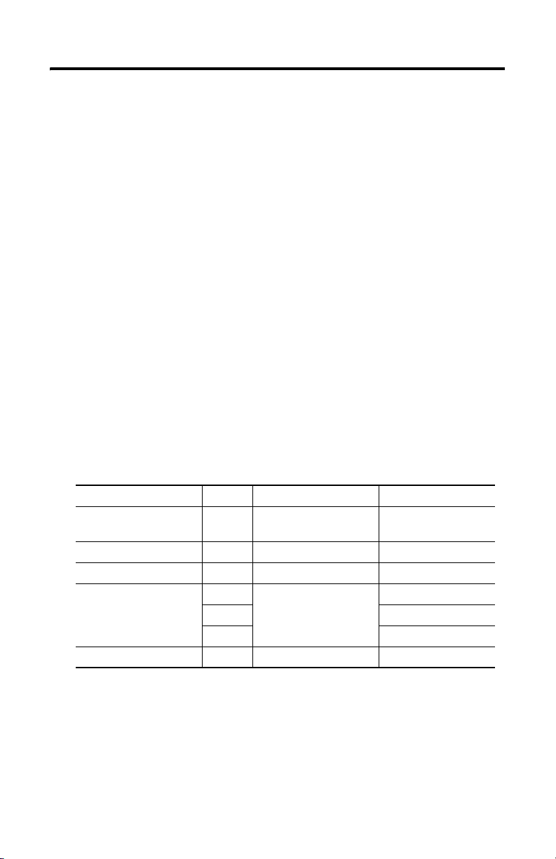
Description Quantity Use To This Computer
Wall or machine
mounting brackets
VESA mounting bracket 1 VESA mount VersaView 200R
DIN rail bracket 1 DIN rail mount VersaView 200R
Mounting screws and nuts 8 Wall, machine, DIN rail,
Rack handles 2 Rack mount VersaView 1400R
2 Wall or machine mount VersaView 200R
12 VersaView 1400R
24 VersaView 200R
rack slide, or VESA mount
Publication 6155R-IN001I-EN-P - July 2007
VersaView 700R
VersaView 700R
Page 7
VersaView Industrial Non-display Computers 7
Required Tools
These tools are required to rack- or machine-mount your computer:
• #2 Phillips screwdriver
• Drill motor and drill bit
Mounting Clearances
Review the product dimensions to make sure you allow adequate clearance on the
sides and rear of the computer for ventilation and cable connections. You must also
be able to remove the covers to install or remove peripheral components.
When mounted in an enclosure or high temperature area, the ambient temperature
around the computer must not exceed the operating temperature range.
Install the Computer
The computers support various mounting options.
• Machine mount (200R and 700R)
• Wall mount (200R)
• DIN rail mount (200R)
• Rack mount (1400R)
• VESA mount (200R)
Mount the Computer on a Machine
You can mount the VersaView 200R and 700R computers on a shelf inside a
machine by using mounting brackets. The brackets secure the computer to the
shelf.
1. Attach the two mounting brackets to the bottom of the computer by using
four of the provided screws.
For the 200R computer, use four of the M3 x 5 mm panhead screws, and
torque to 0.678 Nm (6 lb-in).
Publication 6155R-IN001I-EN-P - July 2007
Page 8
8 VersaView Industrial Non-display Computers
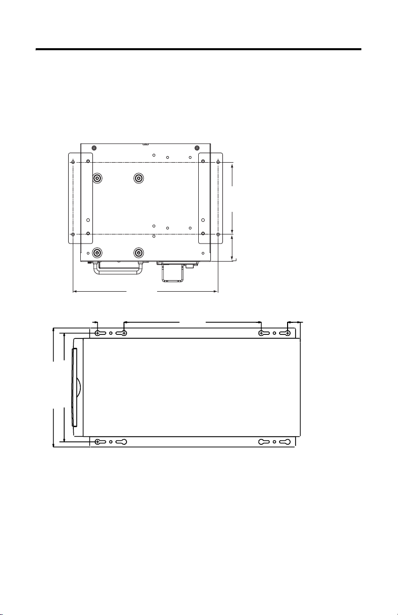
2. Drill holes in the shelf that correspond to holes in the mounting brackets.
• The 200R requires four holes.
• The 700R requires eight holes.
Dimensions are in mm (in.).
VersaView 200R
92 [3.62]
34.5 [1.36]
192 [7.57]
50.00
(1.97)
213.00 (8.39)
233.00 (9.17)
260.00
(10.24)
50.00
(1.97)
24.00
(0.94)
3. Place the computer on the shelf and align the holes in the mounting
brackets with the holes in the shelf.
4. Insert the remaining screws through the mounting bracket into the shelf and
tighten.
For the VersaView 200R computer, use four of the provided, M3 x 5 mm,
panhead screws.
Publication 6155R-IN001I-EN-P - July 2007
Page 9

VersaView Industrial Non-display Computers 9
Mount the Computer on a Wall
You can mount the VersaView 200R computer on a wall inside a machine by using
mounting brackets. The brackets secure the computer to the wall.
1. Attach the two mounting brackets to the rear of the computer by using four
of the provided, M3 x 12 mm panhead screws; torque to 0.678 Nm (6 lb-in).
2. Drill four holes in the wall that correspond to the holes in the mounting
bracket.
Dimensions are in mm (in.).
204.20 [8.04]
192.20 [7.57]
172.20 [6.78]
11.7 [4.61]
92.00 [3.62]
115.40 [4.54]
3. Position the computer against the wall, aligning the holes in the mounting
brackets with the holes in the wall.
TIP
Support the computer with a shelf or other means, to make
installation at the appropriate height easier.
4. Insert the remaining screws through the mounting bracket into the wall and
tighten.
For the VersaView 200R computer, use four M3 x 5 mm, panhead screws.
Publication 6155R-IN001I-EN-P - July 2007
Page 10

10 VersaView Industrial Non-display Computers
Mount the Computer on a DIN Rail
You can mount the VersaView 200R computer on a DIN rail. The DIN rail bracket
mounts to the bottom or back of the computer.
IMPORTANT
Do not mount the computer on a DIN rail in high shock and vibration
environments.
1. Fasten the DIN rail bracket on the bottom or back of the computer by using
four, M3 x 5 mm panhead screws; torque to 0.678 Nm (6 lb-in).
Rear Mount DIN Rail
Bottom Mount DIN Rail
Dimensions are in mm (in.).
152.20 [5.99]
10.5 [0.41]
74.58 [2.94]
152.20 [5.99]
10.5 [0.41]
74.58 [2.94]
Rear Mount DIN Rail
Bottom Mount DIN Rail
2. Mount the computer on a DIN rail and secure it by hand-tightening the
fastener, being careful not to strip the screw.
Publication 6155R-IN001I-EN-P - July 2007
Page 11

VersaView Industrial Non-display Computers 11
Mount the Computer on a Rack
You can install the VersaView 1400R computer in a rack cabinet that conforms to
EIA standards for equipment with 483 mm (19 in.) wide panels. The cabinet must
accommodate the computer’s 4U height and depth, and also provide rear clearance
for cables and air flow. A cabinet with a depth of 610 mm (24 in.) is sufficient.
The computer must be supported by rack slides or fastened to a shelf. The four
flanges of the computer are intended only to horizontally secure the unit to the
front mounting rails of the rack cabinet.
To locate the catalog number for the VersaView approved rack slide, go to the
website:
http://www.ab.com/industrialcomputers
1. Review the product dimensions to confirm that there is adequate space
behind the cabinet for cables and air flow.
2. Install the rack slides inside the rack cabinet.
3. Attach the rack slides to the computer, aligning the rack slides to the
corresponding slides inside the cabinet.
4. Insert the computer in the rack cabinet from the front of the cabinet.
TIP
5. Fasten the two rack handles to the front of the unit by using the included
screws.
6. Horizontally secure the computer to the front mounting rails of the rack
cabinet with the included screws.
Support the computer with a shelf or other means to make
installation at the appropriate height easier.
Publication 6155R-IN001I-EN-P - July 2007
Page 12

12 VersaView Industrial Non-display Computers
VESA Mount the Computer
You can VESA mount the VersaView 200R computer to any of the VersaView
industrial monitors or other surface by using the VESA mounting bracket provided.
1. Orient and attach the VESA mounting bracket to the four, 100 mm VESA
holes that will be used to mount the computer.
Use four, M4 x 8 mm flathead screws with four, M4 x 3 mm nuts. If attaching
the bracket to the back of a VersaView monitor, the nuts are not needed.
Dimensions are in mm (in.).
38 [1.51]
25 [0.98]
100 [3.94]
100 [3.94]
2. Attach the computer to the VESA mounting bracket by using four, M3 x 6
mm screws.
Dimensions are in mm (in.).
150 [5.91]
22 [0.87
15 [0.60]
129 [5.07]
16 [0.64]
Publication 6155R-IN001I-EN-P - July 2007
Page 13

VersaView Industrial Non-display Computers 13
The illustration shows the VersaView 200R computer VESA mounted to the
back of a VersaView 1700M monitor.
Publication 6155R-IN001I-EN-P - July 2007
Page 14

14 VersaView Industrial Non-display Computers
Product Dimensions
Product dimensions for each model of the computer are given in mm (in).
VersaView 200R Computer
172.20 (6.78)
VersaView 700R Computer
192.00 (7.56)
258.00 (10.16)
150.00 (5.91)
115.40 (4.54)
431.30 (16.98)
253.00 (9.96)
Publication 6155R-IN001I-EN-P - July 2007
Page 15

VersaView 1400R Computer
560.00 (22.05)
508.00 (20.00)
517.00 20.34)
481.80 (18.97)
465.00 (18.31)
431.00 (16.97)
VersaView Industrial Non-display Computers 15
176.00 (6.93)
165.10 (6.50)
101.60 (4.00)
Publication 6155R-IN001I-EN-P - July 2007
Page 16

16 VersaView Industrial Non-display Computers
Connect the Keyboard and Mouse
You can plug either a keyboard or mouse into the PS/2 port on the computer. You
can connect both devices by using the PS/2 adapter cable that is shipped with the
computer.
PS/2 Port on the Computers
Publication 6155R-IN001I-EN-P - July 2007
Page 17

VersaView Industrial Non-display Computers 17
Connect Power
The power connection for the computers varies by model.
• The VersaView 200R computer connects to either a 120/240V ac or
9…36V dc power source, depending on the model.
• The VersaView 700R and 1400R computers connect to a 120/240V ac power
source.
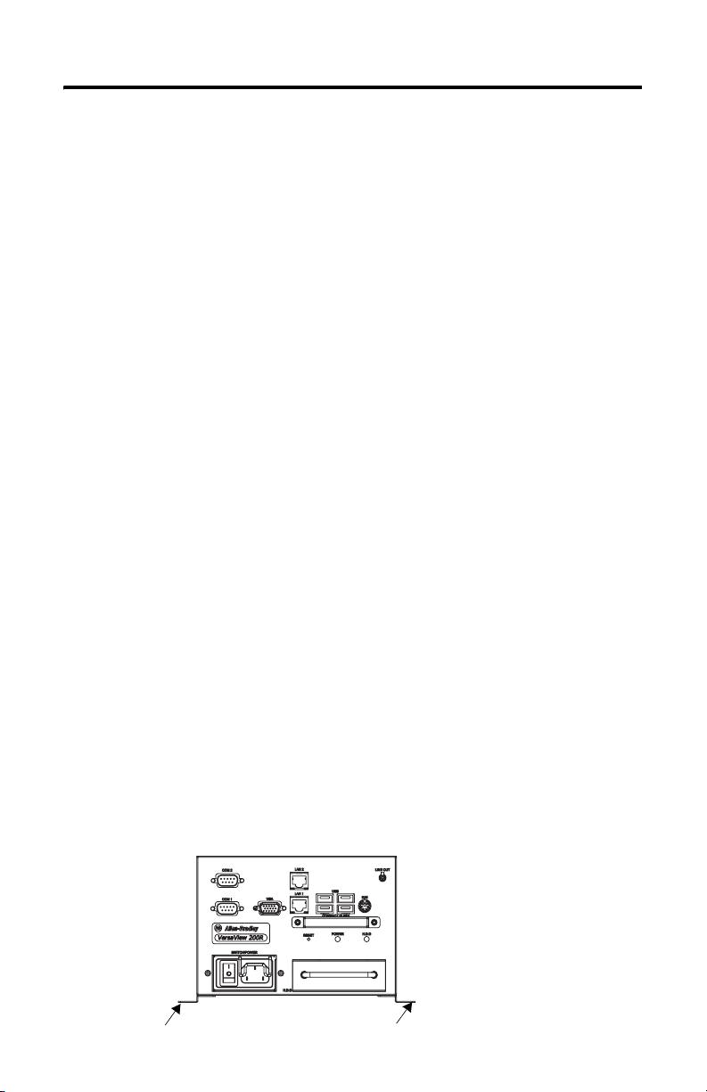
Connect ac Power
Computers with an ac power input use a standard IEC 320 power cord. The power
supply input accepts 120/240V ac and is autoranging.
Power Switch
Power Input
VersaView 200R Computer
Operate the computer in an industrial or control room environment, which uses
some form of power isolation from the public low-voltage mains.
ATTENTION
Connect the ac power cord to a power source with an earth ground to prevent
electrical shock. Failure to follow this warning could result in electrical shock.
The computer circuit should have its own disconnect. Use an uninterruptible
power source (UPS) to protect against unexpected power failure or power
surges.
Always shut down the operating system before removing power to minimize
performance degradation and operating system failures.
Publication 6155R-IN001I-EN-P - July 2007
Page 18

18 VersaView Industrial Non-display Computers
Connect dc Power
The power supply on the VersaView 200R computer has a dc input terminal block
for connecting to a 9…36V dc power source.
ATTENTION
Connect the dc ground connection to a power source with an earth ground to
prevent electrical shock. Failure to follow this warning could result in electrical
shock.
The computer circuit should have its own disconnect. Use an uninterruptible
power source (UPS) to protect against unexpected power failure or power
surges.
Always shut down the operating system before removing power to minimize
performance degradation and operating system failures.
Follow these steps to connect the VersaView 200R computer to a 9…36V dc power
source.
1. Turn off the main power switch or breaker.
2. Route the power wires from your dc power supply and connect the leads to
the dc input terminal block.
-V
…36V dc
9
+V
-V
+V
…36V dc
9
3. Tighten the screw terminals to provide a good connection.
4. Secure the terminal block connector to the computer by using the two side
screws.
5. Restore power.
Publication 6155R-IN001I-EN-P - July 2007
Page 19

VersaView Industrial Non-display Computers 19
Connect to the Network
The computer connects to the Ethernet network by using CAT5 or CAT5E
twisted-pair Ethernet cabling with RJ45 connectors.
IMPORTANT
To prevent performance degradation of Ethernet communication, do not subject
the computer or cables to extreme radiated or conducted high-frequency noise.
Proper cable routing and power conditioning is required for reliable Ethernet
communication in industrial environments. Rockwell Automation recommends
that you route all Ethernet cabling through dedicated metal conduits. Installing
ferrite bead filters at the cable ends may also improve reliability.
Replace the Battery
The computers use nonvolatile memory that requires a battery to retain system
information when power is removed. The lithium battery is in a battery holder on
the computer’s CPU board.
• For the VersaView 700R and 1400R computer, replace this battery as needed
with a Panasonic battery, part number CR2032, or equivalent.
• For the VersaView 200R computer, replace the battery as needed with a
specially-packaged replacement part from Allen-Bradley.
WARNING
To avoid the danger of explosion, replace the battery with only the
recommended equivalent or Allen-Bradley replacement part. Dispose of used
batteries according to the manufacturer’s instructions.
Ship or Transport the Product
If you need to ship the product via common carrier or otherwise transport it to
another location, you must first uninstall the product and place it in its original
packing material.
ATTENTION
Do not ship or transport the product when it is installed in a machine, panel, or
rack. Doing so may cause damage to the product. You must uninstall the
product and place it in its original packing material before shipping. Rockwell
Automation is not responsible for damage incurred to a product that is shipped
or transported while installed in a machine, panel, or rack.
Publication 6155R-IN001I-EN-P - July 2007
Page 20

20 VersaView Industrial Non-display Computers
Specifications
VersaView Industrial Non-display Computers
Attribute Value
Electrical
Input voltage, ac 90…264V ac, autoranging
Line frequency 47…63 Hz
Power consumption, ac
200R
700R
1400R
Input voltage, dc
200R 9…36V ac, autoranging
Power consumption, dc
200R 30 W (0.84 A @ 36V dc, 3.34 A @ 9V dc)
Mechanical
Weight, approx.
200R
700R
1400R
Dimensions (HxWxD), approx.
200R
700R
1400R
30 W (0.5 A @ 100V rms, 0.28 @ 240V rms)
130V A (1.3 A @ 100V rms, 0.54 A @ 240V rms)
150V A (1.5 A @ 100V rms, 0.63 A @ 240V rms)
2.5 kg (5.6 lb)
10.8 kg (23.7 lb)
17.4 kg (38.3 lb)
115 x 172 x 150 mm (4.54 x 6.78 x 5.91 in.)
258 x 192 x 431 mm (10.16 x 7.56 x 16.98 in.)
176 x 482 x 560 mm (6.93 x 18.97 x 22.05 in.)
Environmental Specifications
Attribute Value
Temperature, operating 0…50 °C (32…122 °F)
Temperature, nonoperating -20…60 °C (-4…140 °F)
Relative humidity 10…90% noncondensing
Shock, operating 15 g (1/2 sine, 11 ms)
Shock, nonoperating 30 g (1/2 sine, 11 ms)
Vibration, operating
200R, 6155R, rotating hard drive
200R, 6155F, solid-state drive
700R and 1400R
Vibration, nonoperating 0.012 in. p-p, 10…57 Hz; 2 g peak, 57…500 Hz
Enclosure ratings NEMA Type 1
Publication 6155R-IN001I-EN-P - July 2007
1 G rms random
0.012 in. p-p, 10…57 Hz; 2 g peak, 57…500 Hz
0.006 in. p-p, 10…57 Hz; 1 g peak, 57…500 Hz
Page 21

VersaView Industrial Non-display Computers 21
Certification
c-UL-us UL 60950 recognized component, c-UL 950 recognized component, or
CE Marked for all applicable directives
RoHS compliant
C-Tick Australian Radiocommunications Act, compliant with:
(1)
See http://ab.com for declarations of conformity, certificates, and other certification details.
(1)
UL/c-UL listed when marked
EMC 89/336/EEC
LVD 73/23/EEC
AS/NZS CISPR 11; Industrial Emissions
Additional Resources
For additional information on the VersaView Non-display Computers, refer to the
following publications.
Resource Description
VersaView Industrial Non-display
Computer User Manual, publication
6155R-UM001
Cloning Utility Technical Data,
publication 6000-TD001
Gives an overview of the system and provides procedures
to install the computer, set up computer connections,
operate the computer, and troubleshoot the computer.
Provides information on how to create and restore a backup
image of your computer’s hard drive.
These publications are on the VersaView System Accessories/Cloning CD, which
are shipped with your computer. You can download electronic versions of these
publications from the Rockwell Automation website:
http://literature.rockwellautomation.com
Publication 6155R-IN001I-EN-P - July 2007
Page 22

22 VersaView Industrial Non-display Computers
Publication 6155R-IN001I-EN-P - July 2007
Page 23

VersaView Industrial Non-display Computers 23
Publication 6155R-IN001I-EN-P - July 2007
Page 24

Rockwell Automation Support
Rockwell Automation provides technical information on the Web to assist you in
using its products. At http://support.rockwellautomation.com
technical manuals, a knowledge base of FAQs, technical and application notes,
sample code and links to software service packs, and a MySupport feature that you
can customize to make the best use of these tools.
For an additional level of technical phone support for installation, configuration,
and troubleshooting, we offer TechConnect Support programs. For more
information, contact your local distributor or Rockwell Automation representative,
or visit http://support.rockwellautomation.com
.
Installation Assistance
If you experience a problem with a hardware module within the first 24 hours of
installation, please review the information that's contained in this manual. You can
also contact a special Customer Support number for initial help in getting your
module up and running.
, you can find
United States 1.440.646.3223
Outside United
States
Monday – Friday, 8am – 5pm EST
Please contact your local Rockwell Automation representative for any
technical support issues.
New Product Satisfaction Return
Rockwell tests all of its products to ensure that they are fully operational when
shipped from the manufacturing facility. However, if your product is not
functioning, it may need to be returned.
United States Contact your distributor. You must provide a Customer Support case number
Outside United
States
Allen-Bradley, Rockwell Automation, TechConnect, and VersaView are trademarks of Rockwell Automation, Inc.
Trademarks belonging to Rockwell Automation are property of their respective companies.
Publication 6155R-IN001I-EN-P - July 2007 PN 41061-282-01(9)
Supersedes Publication 6155R-IN001H-EN-P - February 2007 Copyright © 2007 Rockwell Automation, Inc. All rights reserved. Printed in the U.S.A.
(see phone number above to obtain one) to your distributor in order to
complete the return process.
Please contact your local Rockwell Automation representative for return
procedure.
 Loading...