

Page 1

Installation Instructions
Compact Industrial Non-display Computers
Catalog Numbers 6155R-NSXP, 6155R-NPXP, 6155R-NPXPDC, 6155F-NPXP, 6155F-NPWE, 6155F-NPXPDC,
6155F-NPWEDC
Topi c Pag e
Important User Information 2
Precautions 3
Computer O ptions 4
Operating Systems 4
Parts List 5
Hardware Fe atures 6
Install the Computer 8
Connect Peripherals 12
Apply Power 13
Connect to a Network 15
Real-time Clock (RTC) Battery 16
Ship or Transport the Computer 17
Specifications 17
Additional Resources 19
Page 2
2 Compact Industrial Non-display Computers
Important User Information
Solid-state equipment has operational characteristics di ffering from those of electromechanical equipment. Safety Guidelines for
the Application, Installation and Maintenance of Solid State Controls (publication SGI-1.1
Automation sales office or online at http://www.rockwellautomation.com/literature/
between solid-state equipment and hard-wired electromechanical devices. Because of this difference, and also because of the
wide variety of uses for solid-state equipment, all persons responsible for applying this equipment must satisfy themselves that
each intended application of this equipment is acceptable.
In no event will Rockwell Automation, Inc. be responsible or li able for indirect or consequential damages resulting from the use or
application of this equipment.
The examples and diagrams in this manual are included solely for illustrative purposes. Because of the many variables and
requirements associated with any particular installation, Rockwell Automation, Inc. cannot assume responsibilit y or liability for
actual use based on the examples and diagrams.
No patent liability is assumed by Rockwell Automation, Inc. with respect to use of information, circuits, equipment, or software
described in this manual.
Reproduction of the contents of this manual, in whole or in part, without written permission of Rockwell Automation, Inc., is
prohibited.
Throughout this manual, when necessary, we use notes to make you aware of safety considerations.
WARNIN G: Identifies information about practices or circumstances that can cause an explosion in a
hazardous environment, which may lead to personal injury or death, property damage, or economic
loss.
available from your local Rockwell
) describes some important differences
ATTENTION: Identifies information about practices or circumstances that can lead to personal injury or
death, property damage, or economic loss. Attentions help you identify a hazard, avoid a hazard and
recognize the consequences.
SHOCK HAZARD: Labels may be on or inside the equipment, for example, a drive or motor, to alert
people that dangerous voltage may be present.
BURN HAZARD: Labels may be on or inside the equipment, for example, a drive or motor, to alert
people that surfaces may reach dangerous temperatures.
IMPORTANT Identifies information that is critical for successful application and understanding of the product.
Rockwell Automation Publication 6155R-IN002E-EN-P - July 2013
Page 3

Precautions
Read and follow these precautions for use.
Environment and Enclosure Information
ATTENTION: This equipment is intended for use in a Pollution Degree 2 industrial environment, in
overvoltage Category II applications (as defined in IEC publication 60664-1), at altitudes up to
2000 m (6561 ft) without derating.
This equipment is considered Group 1, Class A industrial equipment according to IEC/CISPR
Publication 11. Without appropriate precautions, there may be potential difficulties ensuring
electromagnetic compatibility in other environments due to conducted as well as radiated
disturbance.
This equipment is supplied as open type equipment. UL recognized equipment must be mounted
within an enclosure that is suitably designed for those specific environmental conditions that are
present and appropriately designed to prevent personal injury resulting from accessibility to live
parts. The interior of the enclosure must be accessible only by the use of a tool. UL listed
equipment need not be mounted inside another enclosure. Subsequent sections of this publication
may contain additional information regarding specific enclosure type ratings that are required to
comply with certain product safety certifications.
In addition to this publication, see the following:
• Industrial Automation Wiring and Grounding Guidelines, publication 1770-4.1, for additional
installation requirements
• NEMA Standards publication 250 and IEC publication 60529, as applicable, for explanations of
the degrees of protection provided by different types of enclosure
Compact Industrial Non-display Computers 3
European Union Directive Compliance
This product meets the European Union Directive requirements when installed within the European
Union or EEA regions and have the CE mark. A copy of the declaration of the conformity is
available at http://www.rockwellautomation.com/rockwellautomation/certification/overview.page
ATTENTION: This equipment is intended to operate in an industri al or control ro om environment,
which uses some form of power isolation from the public low-voltage mains. Some computer
configurations may not comply with the EN 61000-3-2 Harmonic Emissions standard as specified
by the EMC Directive of the European Union. Obtain permission from the local power authority
before connecting any computer configuration that draws more than 75 W o f AC power directly
from the public mains.
To comply with EN 55024 and EN 61000-6-2, the Ethernet port LAN cable must be less than 30 m
(98.42 ft), used only indoors, and not exit the building at any point. All other I/O cables must be
less than 3 m (9.84 ft) and used only indoors.
Rockwell Automation Publication 6155R-IN002E-EN-P - July 2013
.
Page 4
4 Compact Industrial Non-display Computers
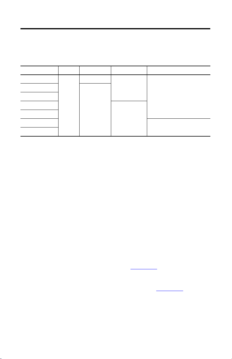
Computer Options
This table summarizes the computer options available for the 200R compact non-display
industrial computers.
Cat. No. Series Package Storage Windows Operating System
6155R-NSXP E Standard Hard-disk drive XP Professional. Service Pack 3
6155R-NPXP Performance
6155R-NPXPDC
6155F-NPXP Solid-state drive
6155F-NPXPDC
6155F-NPWE Embedded Standard 2009
6155F-NPWEDC
(1) Models with a catalog number ending in DC operate from DC power.
(1)
(1)
(1)
Operating Systems
The computers are shipped with one of these Microsoft-licensed operating systems:
• Windows XP Professional, Service Pack 3
• Windows Embedded Standard 2009
No Windows XP operating system updates have been applied to the factory image beyond the
service packs. All available Windows Embedded Standard 2009 operating system updates have
been applied as of September 2009.
For computers with Windows XP, the I386 source directory for Microsoft Windows is on the
system drive of your computer off the root directory, C:\I386. This allows for easy removal and
addition of Windows components.
Computers with rotating hard-disk drives include a recovery partition on the system drive
containing the original factory image. You can use the supplied Computer System Cloning CD
to restore the operating system from the recovery partition and create a new recovery image.
Refer to the Cloning Utility technical data, publication 6000-TD002
Computers with Windows Embedded Standard 2009 include a utility for configuring the
Enhanced Write Filter (EWF) and Hibernate Once, Restore Many (HORM) features. Refer to
the EWF/HORM Configuration Utility technical data, publication 6000-TD003
instructions.
To obtain the original factory image on bootable external-recovery media, contact your local
technical support center.
, for instructions.
, for
Rockwell Automation Publication 6155R-IN002E-EN-P - July 2013
Page 5

Parts List
The computers are shipped with these items:
• Mounting hardware
• AC power cord for AC power models
• Ground bus strip, pre-installed for DC power models
• Installation instructions
• Production test report
• Industrial Computer System Cloning Utility CD (red CD)
Compact Industrial Non-display Computers 5
Rockwell Automation Publication 6155R-IN002E-EN-P - July 2013
Page 6
6 Compact Industrial Non-display Computers
76421
53
1112141516
13
10
9
8
17
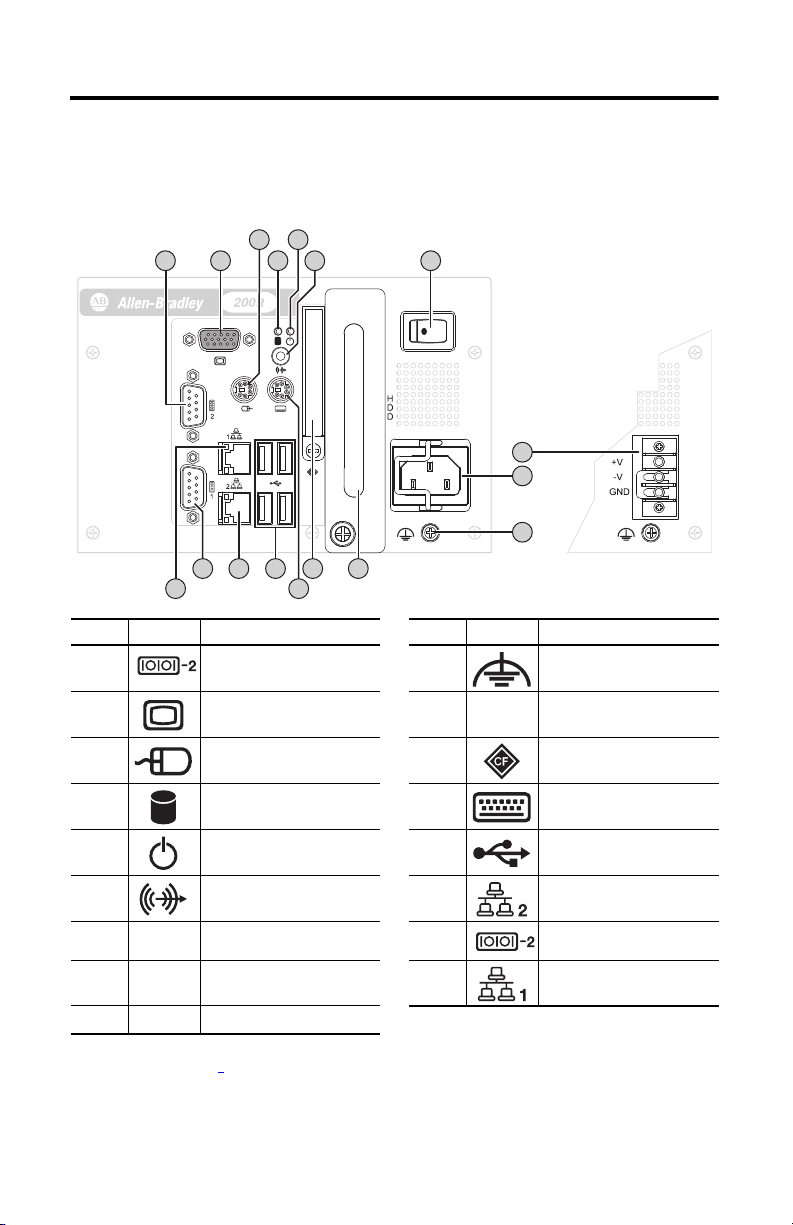
Hardware Features
The illustration shows the hardware features of the 200R compact non-display computer. The
performance computer model is shown.
Item Icon Component Item Icon Component
1Serial COM port 2
(1)
10 Functional ground screw
2 VGA port 11 HDD or SSD
3 PS/2 mouse port 12 CompactFlash Type II card slot
4 HDD or SSD indicator 13 PS/2 keyboard port
5 Power indicator 14 USB ports, 4
6 Audio line-out jack 15 Ethernet port 2
7 Power switch 16 Serial COM port 1
8Power input, DC
(2)
17 Ethernet port 1
(3)
(3)
(RJ45)
(1)
(RJ45)
9Power input, AC
(1) Standard models have one serial COM port and Performance models have two serial COM ports.
(2) Model dependent; see page 4 for further details.
(3) Standard models have one Ethernet port and Performance models have two Ethernet ports.
Rockwell Automation Publication 6155R-IN002E-EN-P - July 2013
Page 7

Compact Industrial Non-display Computers 7
Required Tools
These tools are required for computer installation:
• #2 Phillips screwdriver
• Drill motor and drill bit
• Antistatic wrist strap (recommended)
Mounting Clearances
Review the computer dimensions to make sure you allow adequate clearance around the
computer for ventilation and cable connections.
Use this clearance For
25 mm (1 in.) Sides of computer
51 mm (2 in.) Top of computer
13 mm (0.5 in.)
None Rear of computer
Adequate clearance for any cables used that extend beyond the handle. Front of computer
(1) This clearance is not required when provided mounting hardware is used.
(1)
Bottom of computer
When mounted in an enclosure or high temperature area, the ambient temperature around the
computer must not exceed the operating temperature range.
Rockwell Automation Publication 6155R-IN002E-EN-P - July 2013
Page 8

8 Compact Industrial Non-display Computers
TIP
Mounting Bracket on the Back
Mounting Bracket on the Bottom
Install the Computer
The computers support various mounting options:
• Wall mount
• DIN rail mount
• VESA mount
A bracket with mounting screws is provided for each mounting option.
Mount the Computer on a Wall
You can mount the computer on a wall by using a mounting bracket. See page 11 for the
wall-mount bracket dimensions.
1. Drill and tap four M4 holes in the wall, a minimum of 5 mm, that correspond to the
holes in the mounting bracket.
2. Attach the mounting bracket to the bottom or back of the computer (1).
3. Secure the mounting bracket with the provided M4 x 8 mm panhead screws (2).
Torque the screws to 0.686 N•m (6.072 lb•in).
4. Position the computer against the wall, aligning the holes in the mounting bracket with
the holes in the wall (3).
Support the computer with a shelf or other means to make installation at the appropriate
height easier.
Rockwell Automation Publication 6155R-IN002E-EN-P - July 2013
Page 9

Compact Industrial Non-display Computers 9
IMPORTANT
Mounting Bracket on the Back
Mounting Bracket on the Bottom
5. Insert the remaining M4 panhead screws through the mounting bracket into the wall
and tighten (4).
Mount the Computer on a DIN Rail
You can mount the computer on a DIN rail. The DIN-rail bracket mounts to the back of the
computer. See page 11 for the DIN-rail bracket dimensions.
1. Attach the DIN-rail bracket to the back of the computer (1).
2. Secure the DIN-rail bracket by using four, M4 x 5 mm panhead screws; torque to 0.686
N•m (6.072 lb•in) (2).
Do not mount the computer on a DIN rail in high shock and vibration environments.
Rockwell Automation Publication 6155R-IN002E-EN-P - July 2013
Page 10

10 Compact Industrial Non-display Computers
TIP
IMPORTANT
If you are using an existing DIN rail, skip step 3.
3. Attach and secure the DIN rail to the installation surface (3).
4. Mount the computer on a DIN rail.
a. Insert the upper lip of the DIN-rail bracket into the top edge of the DIN rail.
a. Press the computer firmly against the lower edge of the DIN rail (4).
5. Secure the installation by tightening the fastener on the DIN-rail bracket and torque to
1.18 N•m (10.42 lb•in) (5).
VESA Mount the Computer
You can mount the computer to any Allen-Bradley industrial monitor or other surface by using
the provided VESA mounting bracket. This bracket is compliant with the VESA 100 x 100 mm
mounting hole pattern. See page 11
If you are VESA mounting to the back of the monitor, the computer I/O panel must be facing
down, and the monitor must be mounted vertically and not at an angle.
1. Attach the VESA mounting bracket to the installation surface (1).
2. Secure the VESA mounting bracket with the four M4 x 8 mm flathead screws (2).
3. Place the computer on the VESA mounting bracket (3).
4. Secure the installation with four M4 x 8 mm screws (4).
Torque the screws to 0.686 N•m (6.072 lb•in).
for the VESA mounting bracket dimensions.
Rockwell Automation Publication 6155R-IN002E-EN-P - July 2013
Page 11

Figure 1 - Mounting Bracket Dimensions
172 (6.77)
212 (8.346)
6 (0.236)
114.6
(4.512)
46
(1.811)
64
(2.52)
92
(3.622)
11.3
(0.444)
140 (5.511)
150 (5.90)
192 (7.56)
86 (3.385)
49
(1.929)
46
(1.811)
92
(3.622)
114
(4.488)
80 (3.149)
140 (5.511)
172 (6.771)
8.5 (0.334)
16 (0.629)
14 (0.55)
22 (0.866)
100
(3.94)
156
(6.14)
100 (3.94)
176.4 (6.945)
84
(3.318)
35.85
(1.41)
2 (0.079)
DIN-rail Mounting Bracket
VESA Mounting Bracket
Wall Mounting Bracket All dimensions
are in mm (in.)
Compact Industrial Non-display Computers 11
Rockwell Automation Publication 6155R-IN002E-EN-P - July 2013
Page 12

12 Compact Industrial Non-display Computers
158
(6.22)
115
(4.51)
158 (6.22)172 (6.77)
Top View
Front View Side View
Computer Dimensions
Computer dimensions for the computer are given in mm (in).
Connect Peripherals
Connect the required peripherals such as the keyboard, mouse, and monitor to the
corresponding I/O ports on the computer. Refer to Hardware Features on page 6 for required
connections.
Rockwell Automation Publication 6155R-IN002E-EN-P - July 2013
Page 13

Compact Industrial Non-display Computers 13
TIP
Apply Power
The computer connects to either a 100…240V AC or 9…36V DC power source, depending on
the model.
SHOCK HAZARD: Connect the AC power cord or the DC ground connection to a power source with
an earth ground to prevent electrical shock. Failure to follow this warning could result in electrical
shock.
We recommend that the computer circuit have its own disconnect. Use an uninterruptible power
source (UPS) to protect against unexpected power failure or power surges.
Always shut down the operating system before removing power to minimize performance
degradation and operating system failures.
Remove the AC retention clip, if necessary, before installing the computer in a panel cutout.
Reattach the clip after installing the computer.
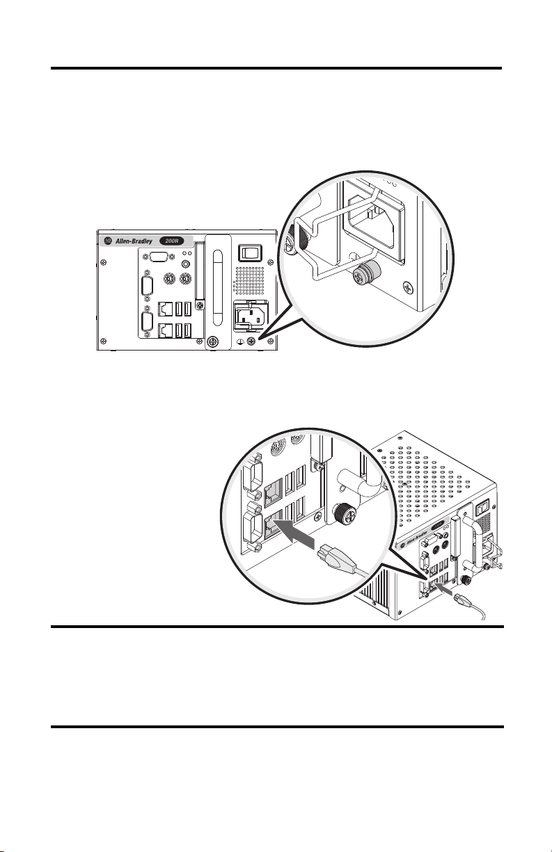
Connect AC Power
A grounded 3-prong IEC320 power cord provides power to a computer with an AC power
input. The power supply input accepts 100…240V AC and is autoranging.
If using an alternate IEC320 cord, make sure the female end of the cord is sized appropriately
for the retention clip.
1. Connect the power cord to the AC power input (1).
2. Secure it in place with the retention clip (2).
Operate the computer in an industrial or control room environment, which uses some form of
power isolation from the public low-voltage mains.
Rockwell Automation Publication 6155R-IN002E-EN-P - July 2013
Page 14

14 Compact Industrial Non-display Computers
9…36V DC
+V
Pre-install ed
Bus Strip
-V
GND
Connect DC Power
Computers with a catalog number ending in DC have a DC input terminal block for connecting
to a 9…36V DC power source.
The DC power option supports operation from either a Safety Extra Low Voltage (SELV) or
Protective Extra Low Voltage (PELV) power source. A pre-installed ground bus strip connects
the DC common and functional ground terminals together. This is to support SELV cases where
the end user requires grounding at the computer.
ATT EN TI ON : Use a Class 2 Safety Extra Low Voltage (SELV) isolated and ungrounded power
supply as input power to the computer. This power source provides protection so that under
normal and single fault conditions, the voltage between the conductors and functional
earth/protective earth does not exceed a safe value.
Follow these steps to connect the computer to a DC power source.
1. Turn off the main power switch or breaker.
2. Secure the DC power wires to the terminal block screws.
3. Secure the DC ground wire to the GND terminal screw.
4. Apply 9…36V DC power to the computer.
Rockwell Automation Publication 6155R-IN002E-EN-P - July 2013
Page 15
Compact Industrial Non-display Computers 15
IMPORTANT
Functional Ground Screw
You are not required to use the functional ground screw for safety and regulatory compliance.
However, if you want a supplemental ground, use the functional ground screw below the power
input.
Connect to a Network
The computers have one or two
Gigabit LAN ports, depending
on the model. The computer
connects to the Ethernet
network by using twisted-pair
Ethernet cabling with RJ45
connectors.
To prevent performance degradation of Ethernet communication, do not subject the computer
or cables to extreme radiation or conducted high-frequency noise.
Proper cable routing and power conditioning is required for reliable Ethernet communication
in industrial environments. We recommend that you route all Ethernet cabling through
dedicated metal conduits. Installing ferrite bead filters at the cable ends can also improve
reliability.
Rockwell Automation Publication 6155R-IN002E-EN-P - July 2013
Page 16

16 Compact Industrial Non-display Computers
IMPORTANT
On Time
(hrs/wk)
Expected Battery
Life (yrs)
04
40 5.5
80 7
Real-time Clock (RTC) Battery
This computer contains a lithium battery that must be replaced during the life of the computer.
The computers use nonvolatile memory that require a battery to retain system information when
power is removed. The RTC battery is on the computer’s CPU board.
The battery life depends on the amount of time the computer is powered on.
If your computer does not display the correct time and date, replace the battery.
ATT EN TI ON : A risk of fire and chemical burn exists if the battery is not handled properly:
• Do not disassemble, crush, puncture, or short external contacts
• Do not expose the battery to temperatures higher than 60 °C (140 °F).
• Do not dispose of a used battery in water or fire.
For safety information on handling lithium batteries, see Guidelines for Handling Lithium
Batteries, publication AG- 5.4
.
WARNI NG: To prevent voiding your product warranty, use only Allen-Bradley approved
replacement parts and accessories.
Replacing the battery results in all BIOS settings returning to their default settings.
BIOS settings other than default must be reconfigured after replacing the battery.
This product contains a hermetically-sealed lithium battery that may need to be replaced
during the life of the product.
At the end of its life, the battery contained in this product should be collected separately from
any unsorted municipal waste.
Rockwell Automation Publication 6155R-IN002E-EN-P - July 2013
Page 17

Compact Industrial Non-display Computers 17
Ship or Transport the Computer
If you need to ship the computer via common carrier or otherwise transport it to another
location, you must first uninstall the computer and place it in its original packing material.
ATTENTION: Do not ship or transport the computer when it is installed in a machine, panel, or
rack. Doing so can cause damage to the computer. You must uninstall the computer and place it in
its original packing material before shipping. Rockwell Automation is not responsible for damage
incurred to a computer that is shipped or transported while installed in a machine, panel, or rack.
Specifications
Mechanical
6155R-NSXP, 6155R-NPXP, 6155R-NPXPDC, 6155F-NPXP, 6155F-NPWE,
Attribute
Weight, approx 5 kg (11 lb)
Dimensions (HxWxD), approx 115 x 172 x 158 mm (4.51 x 6.77 x 6.22 in.),
Electrical
Attribute
Input voltage, AC 100…240V, autoranging
Line frequency 47…63 Hz
Power consumption, AC 35 W (0.64 A @ 100V rms, 0.37 @ 240V rms)
Input voltage, DC 9…36V, autoranging
Power consumption, DC 35 W (3.89 A @ 9V, 0.97 A @ 36V)
6155F-NPXPDC, 6155F-NPWEDC
excluding handle and connector
6155R-NSXP, 6155R-NPXP, 6155R-NPXPDC, 6155F-NPXP, 6155F-NPWE,
6155F-NPXPDC, 6155F-NPWEDC
64VA @ 100, 88.8VA @ 240V
Rockwell Automation Publication 6155R-IN002E-EN-P - July 2013
Page 18

18 Compact Industrial Non-display Computers
Environmental
Attribute
Temperature, operating 0…55 °C (32…131 °F)
Temperature, nonoperating -20…60 °C (-4…140 °F)
Relative humidity 10…90% noncondensing
Shock, operating
Shock, nonoperating
Vibr ation, operat ing
6155R
6155F
Vibration, nonoperating
(1) Applies to wall-mounted computers only.
(1)
(1)
(1)
(1)
6155R-NSXP, 6155R-NPXP, 6155R-NPXPDC, 6155F-NPXP, 6155F-NPWE,
6155F-NPXPDC, 6155F-NPWEDC
15 g (1/2 sine, 11 ms)
30 g (1/2 sine, 11 ms)
0.006 in. p-p, (10…57 Hz); 1 g peak, (57…640 Hz)
0.012 in. p-p, (10…57 Hz); 2 g peak, (57…640 Hz)
0.012 in. p-p, (10…57 Hz); 2 g peak, (57…640 Hz)
Certifications
(1)
Attribute
c-UL-us
CE Marked for all applicable directives
RoHS European RoHS
C-Tick Australian Radiocommunications Act, compliant with:
(1) See http://www.rockwellautomation.com/rockwellautomatio n/certification/overview.page for declarations of conformity, certificates, and other
certification details.
6155R-NSXP, 6155R-NPXP, 6155R-NPXPDC, 6155F-NPXP, 6155F-NPWE,
6155F-NPXPDC, 6155F-NPWEDC
UL/c-UL Listed per UL 60950-1 and CSA C22.2 No. 60950-1-03
EMC 2004/108/EC
LVD 2006/95/EC
China RoHS
Turkey RoHS (EEE Yöne tmeliğine Uygundur. In Conformity with the EEE Regulation)
AS/NZS CISPR 11; Industrial Emissions
Rockwell Automation Publication 6155R-IN002E-EN-P - July 2013
Page 19

Compact Industrial Non-display Computers 19
Additional Resources
For additional information on compact non-display computers, refer to the following publications.
Resource Description
Industrial Non-display Computer User
Manual, publication 6155R-UM002
Cloning Utility Technical Data,
publication 6000-TD002
Diagnostic Utility for Industrial
Computers, publication 6000-TG001
EWF and HORM Configuration Utility
Technical Data, publication 6000-TD003
You can view or download publications at http://www.rockwellautomation.com/literature. To
order paper copies of technical documentation, contact your local Allen-Bradley distributor or
Rockwell Automation sales representative.
Gives an overview of the system and provides procedures to install the computer, set
up computer connections, operate the computer, and troubleshoot the computer.
Provides information on how to create and restore a backup image of your computer’s
hard drive.
Provides information on how to diagnose hardware issues with industr ial computers.
Provides information on how to configure Enhanced Write Filter (EFW) and Hibernate
Once, Restore Many (HORM) features for computers with the Windows Embedded
Standard 2009 operating system.
Rockwell Automation Publication 6155R-IN002E-EN-P - July 2013
Page 20

Rockwell Automation Support
Rockwell Otomasyon Ticaret A.Ş., Kar Plaza İş Merkezi E Blok Kat:6 34752 İçerenköy, İstanbul, Tel: +90 (216) 5698400
Rockwell Automation provides technical information on the Web to assist you in using its products.
At http://www.rockwellautomation.com/support
links to software service packs, and a MySu pport feature that you can customize to make the best use of these tools. You can also visit
our Knowledgebase at http://www.rockwellautomation.com/knowledgebase
forums, software updates, and to sign up for product notification updates.
For an additional level of technical phone support for installation, configuration and troubleshooting, we offer TechConnect
support programs. For more information, contact your local distributor or Rockwell Automation representative, or visit
http://www.rockwellautomation.com/support/
Installation Assistance
If you experience a problem within the first 24 hours of installation, please review the information that's contained in this manual.
You can also contact a special Customer Support number for initial help in getting your product up and running.
United States or Canada 1.440.646.3434
Outside United States or
Canada
Use the Wor ldwi de Lo cato r
http://www.rockwellautomation.com/rockwellautomation/support/overview.page
or contact your local Rockwell Automation representative.
New Product Satisfaction Return
Rockwell Automation tests all of its products to help ensure that they are fully operational when shipped from the manufacturing
facility. However, if your product is not functioning and needs to be returned, follow these procedures.
, you can find technical manuals, technical and application notes, sample code and
for FAQs, technical information, support chat and
SM
.
at
,
United States Contact your distributor. You must provide a Customer Suppor t case number (call the phone number
Outside United States Pl ease contact your local Rockwell Automation representative for the return procedure.
above to obtain one) to your distributor to complete the return process.
Documentation Feedback
Your comments will help us serve your documentation needs better. If you have any suggestions on how to improve this document,
complete this form, publication RA-DU002
Allen-Bradley, Rockwell Software, and Rockwell Automation are trademarks of Rockwell Automation, Inc.
Trademarks not belonging to Rockwell Automation are property of their respective companies.
Publication 6155R-IN002E-EN-P - July 2013 PN-30420
Supersedes Publication 6155R-IN002D-EN-P - September 2012 Copyright © 2013 Rockwell Automation, Inc. All rights reserved. Printed in China.
, available at http://www.rockwellautomation.com/literature/.
DIR 10000039351 (Version 02)
 Loading...