

Page 1
Installation Instructions
Time
PHOTOSWITCH® Bulletin 45PVA Part Verification Array
IMPORTANT: SAVE THESE INSTRUCTIONS FOR FUTURE USE.
Description
The Allen-Bradley 45PVA is a photoelectric Parts Verification
Features
S Robust metal enclosure with super slim 13mm profile
Array designed for bin picking applications and object
detection in the parts assembly industry. When used as part of
a suitably configured bin-picking system, the 45PVA effectively
prevents mispicks to enhance efficiency and minimize down
time. It is also the ideal solution to address the “error proofing”
initiatives prevalent in the automotive industry.
The 45PVA uses an array of LEDs to create a light screen that
can be spanned across bins at an assembly station. By
mounting the sensors on parts bins and wiring them into a
controller programmed with the necessary logic, a virtually
error-free bin-picking process can be achieved. ‘Job lights’ on
the 45PVA will not only show the assembler the bins required
to complete the current process, but will also indicate the
correct picking sequence. In the event the assembler attempts
to pick an incorrect part, a selectable warning light on the
45PVA will illuminate to indicate the error; additional fault
enunciation can be achieved via controller logic in conjunction
with a tower light or audible alarm.
S Large highly-visible job indicator lights
S Optional Red warning light indicator to notify operator of
incorrect component selection
S Dip switch selectable lighting operation for job lights
S Transmitted beam or selectable retroreflective/diffuse
sensing modes
S NPN or PNP dip switch selectable output reduces inventory
S Two frequency dip switch selectable cross talk protection
S Different sizes are available for different component racks.
Transmitted beam models are available in four sizes (100
mm (4 in), 225 mm (9 in), 300 mm (12 in), and 375 mm (15
in)). Retroreflective/diffuse models are available in two
sizes (100 mm (4 in) and 225 mm (9 in)).
In addition to increasing efficiency and quality control by
preventing faults in the bin-picking process, the 45PVA is
instrumental in personnel stress reduction and the
simplification of personnel training—especially in multi-lingual
facilities.
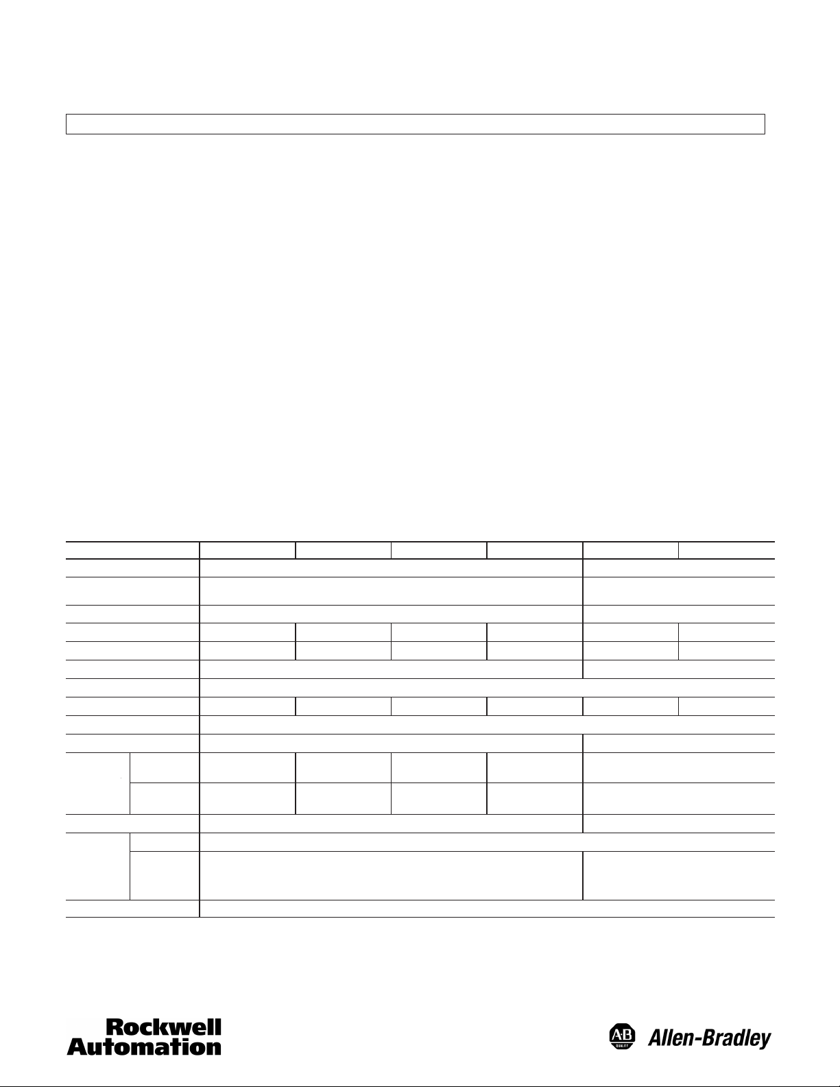
General Specifications
Description 45PVA–1LEB1–F4 45PVA–1LEB2–F4 45PVA–1LEB3–F4 45PVA–1LEB4–F4 45PVA–2LEA1–F4 45PVA–2LEA2–F4
Detection
Range
Detection Object
No. of Optical Axis
Detection Width
Optical Axis Pitch
Power Supply
Current Consumption (Max)
Output Mode
Operation Mode
Response
Time
Indicator Job/Warning
Short Circuit Protection
Standard
Interference
Protection
Light Source
Power and
Output
5 10 13 16 4 8
100 mm 225 mm 300 mm 375 mm 100 mm 225 mm
130 mA 140 mA 150 mA 155 mA 68 mA 78 mA
NPN/PNP Output Selectable; Rating: Current 50mA (30VDC) Max. Residual Voltage 2V or less
Light on: 35 ms
Dark on: 25 ms
Light on: 45 ms
Dark on: 28 ms
Power Indicator—Small Green LED; Receiver Light on Indicator—Small Green LED;
Receiver Dark on Indicator—Small Orange LED
Transmitted–Beam Retroreflective/Diffuse
2m (Max.)
35 mm (Min.) Opaque Object Varies with distance (see chart)
25 mm 29 mm
12 to 26V DC, Ripple 10% (Max.)
Light-on/Dark-on Selectable Target Present = Output On
Light on: 68 ms
Dark on: 42 ms
Light on: 84 ms
Dark on: 52 ms
Infrared LED, Wave-length 880 nm Visible Red LED, 640 nm
Light on: 70 ms
Dark on: 42 ms
Light on: 88 ms
Dark on: 54 ms
Large Green/Red
Light on: 94 ms
Dark on: 58 ms
Light on: 116 ms
Dark on: 72 ms
Built-in
2 m (Retro Mode)/400 mm Gray Paper
Power Indicator—Small Green LED (blinks
orange during power up sensitivity
adjustment). Output Indicators—Small
(Diffuse)
120 ms
120 ms
Orange LED.
1
Page 2
General Specifications (continued)
Description 45PVA–1LEB1–F4 45PVA–1LEB2–F4 45PVA–1LEB3–F4 45PVA–1LEB4–F4 45PVA–2LEA1–F4 45PVA–2LEA2–F4
Cross Talk Elimination
Material
Wiring
Environmental Characteristics
Selectable Frequency
Enclosure: Aluminum, Lens: Polycarbonate, End plate: Resin
4-Pin DC Micro Connection with 2m pigtail
Ambient Light
Operating TemperatureĊC (F)
Storage TemperatureĊC (F)
Operating Humidity
Enclosure Protection
Vibration Resistance
Shock Resistance
Dielectric Strength
Description
Transmitter Receiver
Job Indicator
(Green)
Power Indicator
Switch Cover
Cable (Gray)
(Green)
Dark Indicator
(Orange)
Switch Cover
10,000 lx (Max.)
0…50_ (32…122_) -10…50_ (14…122_)
–25…70_ (–13…158_)
35% to 85 %RH
IP 62
10Hz to 55Hz, 1.5mm Amplitude, 2 hours, X,Y and Z directions
500 m/s2 3 times X,Y and Z directions
1,000VAC for 1 minute
Job Indicator (Green)
Warning Indicator (Red)
(optional functionality)
Light Status Indicator
(Green/Orange)
Cable (Black)
Retroreflective/Diffuse
Output Indicator
(Orange)
Switch Cover
Job Indicator (Green)
Warning Indicator (Red)
(optional functionality)
Power Indicator (Green)
(Blinks orange during
power up sensitivity
adjustment)
Cable (Black)
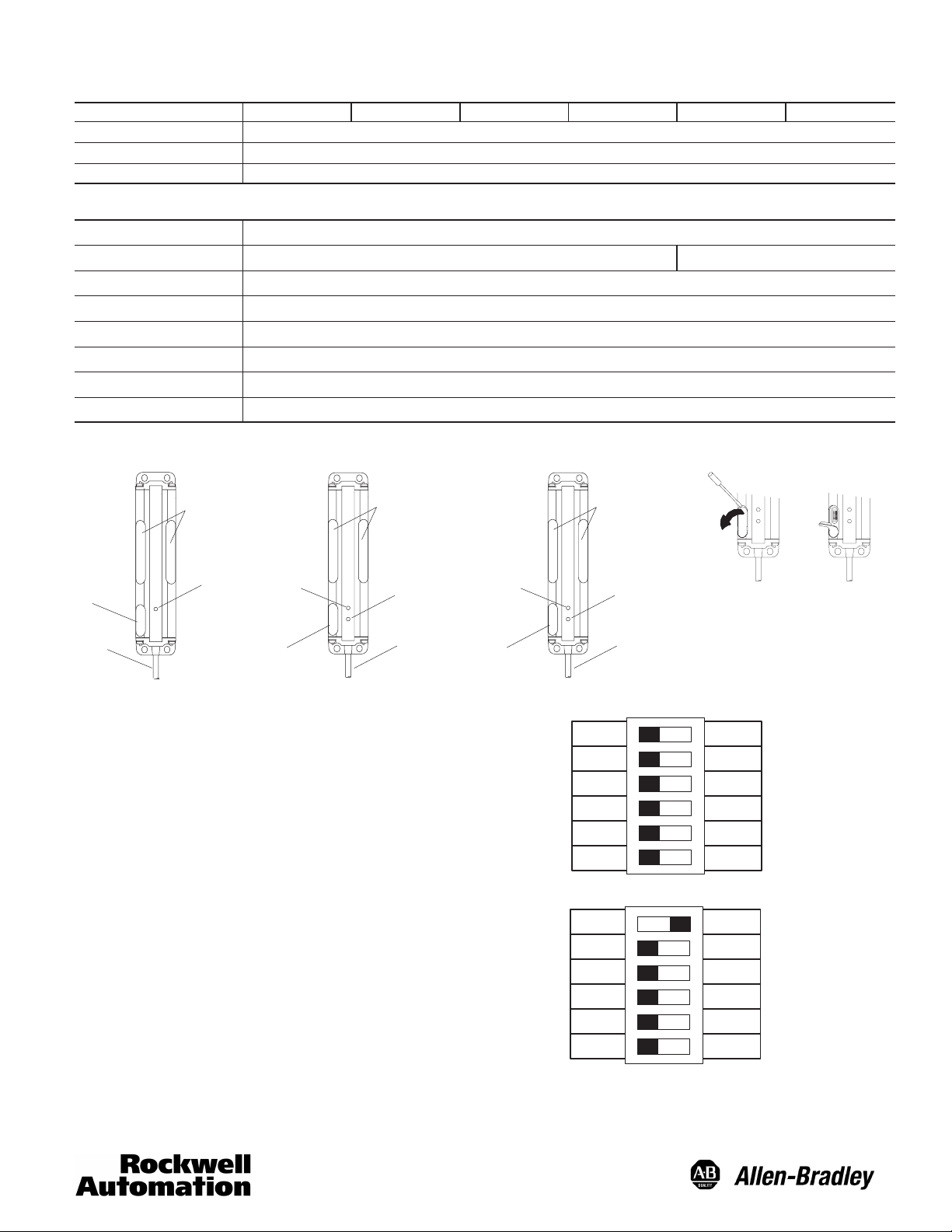
Mode Selection Switches
Mode Selection Switches
Transmitted Beam
1. Job indicator mode
2. Job indicator speed control for flashing
3. Selectable operation mode (receiver only)
4. Selectable warning indicator (receiver only)
5. NPN/PNP selectable switch
6. Selectable frequency
Retroreflective/Diffuse
1. Operating mode selection
2. Automatic sensitivity adjustment ON/OFF
3. Output Normally Open/Normally Closed
4. Selectable warning indicator
5. NPN/PNP selectable switch
6. Selectable frequency
Note: Only operate the mode selection switches with the power supply turned off.
Factory Default Settings
1
Flash
2
Fast
PNP
A
Diffuse
N.O.
PNP
Freq A
3
4
5
6
1
2
3
4
5
6
Dark_on
Warning_on
Auto Adjust
Warning_on
Light
Slow
Light_on
Warning_off
NPN
B
Retro
Auto Adj Off
N.C.
Warning_off
NPN
Freq B
2
Page 3
1. Job indicator mode (transmitted beam)
Either a steady light or flashing light mode can be selected.
Operating mode selection (retro/diffuse)
Retroreflective or diffuse operating mode can be selected
2. Job indicator speed control for flashing (transmitted beam)
The flashing speed can be selected as slow or fast.
Automatic sensitivity adjustment ON/OFF (retro/diffuse)
The automatic sensitivity adjustment can be turned on or off. (Regardless of this setting, sensitivity is always adjusted when
the power is turned on.)
3. Selectable operation mode (transmitted beam receiver)
The output mode of the receiver can be selected for light or dark operate.
Output Normally Open/Normally Closed (retro/diffuse)
The output mode can be selected for Normally Open or Normally Closed.
4. Selectable warning indicator
Select the warning indicator mode.
5. NPN/PNP selectable switch
Select the transistor mode for the output and the job indicator input.
NPN Output (PNP Input)
PNP Output (NPN Input)
6. Selectable frequency
The frequency can be switched to eliminate crosstalk.
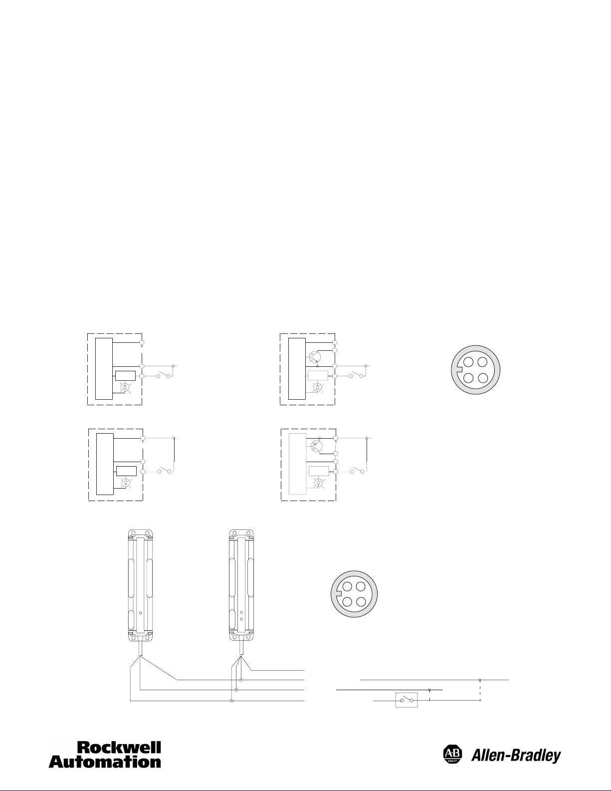
Input/Output Circuit and Wiring
The NPN/PNP input of the job indicator and the NPN/PNP output are selected by mode switch.
NPN Output
(selected)
Transmitter
1
4
Job
2
Pin 1 (Brown): 12 to 24V DC
Pin 3 (Blue): 0V
Pin 2 (Pink or White):
Job Indicator Input
Transmitted Beam Receiver and
Retroreflective/Diffuse
1
Pin 1 (Brown): 12 to 24V DC
4
Pin 4 (Black): Output (NPN)
Pin 3 (Blue): 0V
Job
2
Pin 2 (Pink or White):
Job Indicator Input
Face View Male Receptacle (Sensor)
DC Micro
1324
PNP Output
(selected)
Transmitter Receiver
1
Pin 1 (Brown): 12 to 24V DC
Pin 3 (Blue): 0V
4
Job
2
Pin 2 (Pink or White):
Job Indicator Input
Transmitter (not required for
Retroreflective/Diffuse models)
Transmitted Beam Receiver
and Retroreflective/Diffuse
4
1
3
2
1
Pin 1 (Brown): 12 to 24V DC
4
Pin 4 (Black): Output (PNP)
3
Pin 3 (Blue): 0V
Job
2
Pin 2 (Pink or White):
Job Indicator Input
Face View Male Receptacle (Sensor)
DC Micro
1324
Black: Out
Brown: 12 to 24V DC
Blue: 0V
White: Job Indicator Input
(NPN Output
Selected)
(PNP Output
Selected)
Note: Warning light requires no wiring. It is triggered using internal logic when the input is off (low) and the target is present.
3
Page 4

Installation
Cable
Cable
Cable
Cross-Talk Elimination
When two or more sensors are installed close together the sensors may interfere with each other and not operate correctly. In that
case, flip the frequency switch on one set of sensors. For transmitted beam, transmitter and receiver pairs must be set to the
same frequency.
1
2
3
4
5
6
Select switch for frequency
1
2
3
4
5
6
Transmitted Beam Models
Transmitter Receiver
Transmitter Receiver
1
2
3
4
5
6
Select switch for frequency
1
2
3
4
5
6
Retroreflective/Diffuse Models
1
2
3
4
5
6
1
2
3
4
5
6
Bin #1
Bin #2
An additional method for dealing with sensor cross talk interference is by alternating the direction of transmitter/receiver pairs. The
same effect can be achieved with the retro/diffuse model by setting the units up back to back.
Transmitted Beam Models Retroreflective/Diffuse Models
Transmitter Receiver
Bin #1 Bin #2
TransmitterReceiver
4
Page 5

Minimum Detectable Object Size
Retroreflective Mode
90
80
70
60
50
40
30
Minimum Object SizeĊmm
20
10
Operating Indicator
Transmitter Receiver
Retroreflective/Diffuse
Power Indicator
(Green)
Output Indicator (Orange)
Power Indicator (Green)
Blinks orange & green during power up sensitivity
adjustment
Dark Indicator (Orange)
Lights when the beam is interrupted
Light Status Indicator (Green/Orange)
Green: Stable light condition (>1.5 x gain).
Orange: Misaligned or interrupted beam.
0
0 0.5
(1.6 ft)
1
(3.3 ft)
DistanceĊm (ft)
1.5
(4.9 ft)
TypicalSpecified
2
(6.6 ft)
Job Indicator & Warning Indicator
The green job indicator LED is on when the input to the PVA is on. The output signal is turned on when the target is present
(when in Dark On or Normally Open mode). For example, when the operator’s hand is in the bin. The red warning indicator is on
when the target is present and the input is off.
OFF ON OFF
Input
Green Job Indicator (determined by input)
Target Present (operator hand in bin)
Output (determined by target present)
Red Warning Indicator
ON
ON
ON
ON
ON
ON
Light Margin and Operating Indicators (transmitted beam receiver only)
x1.5
x1.0
Dark Indicator
(Orange)
Light status
Indicator
Note: Use a dry, soft cloth for cleaning the lens and case. Lightly wipe it off. Never use solvents such as thinner.
Light
Orange
Operating Level
Green
Orange
5
Stable light
area
Unstable light
area
Dark area
Light
Page 6

Dimensions—mm (inches)
Switch Cover
4.0 (0.15)
Cat. No.
45PVA-1LEB1-F4
45PVA-1LEB2-F4
45PVA-1LEB3-F4
45PVA-1LEB4-F4
45PVA-2LEA1-F4
45PVA-2LEA2-F4
Ê N = Number of optical axis.
13
(0.51)
Light Status Indicator,
Green/Orange (Receiver)
Power, Green (Retro/Diffuse)
N Ê
5 100 (3.9) 130 (5.1) 140 (5.5) 25 (1.0)
10 225 (8.9) 255 (10.0) 265 (10.4) 25 (1.0)
13 300 (11.8) 330 (13.0) 340 (13.4) 25 (1.0)
16 375 (14.8) 405 (16.0) 415 (16.3) 25 (1.0)
4 87 (3.4) 130 (5.1) 140 (5.5) 29 (1.1)
8 203 (8.0) 255 (10.0) 265 (10.4) 29 (1.1)
L1
M
P
18
(0.7)
57 (2.24) 51 (2.0)
L2
Dark Indicator, Orange (Receiver)
Power Indicator, Green (Transmitter)
Output ON Indicator, Orange (Retro/Diffuse)
45PVR-1LEB1-F4 Ser A
Dimensions—mm (inches)
M L1 L2 P
Job
Indicator
32
(1.25)
4.5 (0.17) Dia.
Accessories
Mounting Brackets
#60-2773 (2 brackets)
(included)
20
(0.78)
(0.91)
16
(0.63)
23
40 (1.57)
18
(0.7)
(0.39)
2 (0.07)
10
4.6
(0.18) Dia.
10
(0.39)
4.6
(0.18) Dia.
6
(0.23)
11
(0.43)
6
Page 7

Optional Mounting Brackets
Mounting brackets available as an option (not included with sensor).
Plastic Bracket
#60-2779 (2 brackets)
Metal Bracket
#60-2772 (2 brackets)
17.0 (0.67)
7.6 (0.30)
18.0
(0.71)
2 x M5 x 0.8
7.4 (0.29)
18.8 (0.74)
34.0 (1.34)
20.1
(0.79)
4.4 (0.17)
(1.06) Dia.
51.8 (2.04)
26.9
18.0
(0.71)
66
(2.60)
28.0 (1.10)
Dia.
2 x 16.0
(0.63)
18.0 (0.71)
68.3 (2.69)
28.0 (1.10)
7.4 (0.29)
5.2 (0.20)
Dia.
7.0 (0.27)
2.5
(0.10)
4 x M4 x 0.7
16.0
(0.63)
9.2 (0.36)
32.0
(1.26)
7
Page 8

Protective Metal Bracket
4
97
(0
08)
Galvanized
#60-277x-1 (2 brackets for transmitted beam models)
#60-278x-1 (1 bracket for retro/diffuse models)
L1
10.0
7.01
(0.27)
(0.39)
17.5
(0.689)
L2
R 3.05
(0.12)
111.3 (4.38)
68.3 (2.69)
51.3 (2.02)
Reflective Tape (included with retroreflective/diffuse models)
Dimensions'mm (inches)
Cat. No. For use with
92-122 45PVA-2LEA1-F4
92-123 45PVA-2LEA2-F4
W L
50 (2) 120 (4.7)
50 (2) 245 (9.6)
(0.196) Dia.
(0.354) Ref.
12.34
(0.486)
27.3 (1.07)
16.3 (0.64)
4 x R 5.08
4 x 4.97
x 4.
2 x R 2.03
.
(0.709)
8.99
(0.20)
Cat. No.
(2 brackets)
60-2775-1 60-2785-1
60-2776-1 60-2786-1
2 x 18
60-2777-1 NA
60-2778-1 NA
(1 bracket)
13.99
(0.55)
R.02Ref.
Internal Radii
Cat. No.
9.5 (0.37)
L1 L2 Material
10.0
(0.39)
130.0
(5.11)
254
(10.03)
330
(12.99)
405
(15.94)
148.36
273.35
(10.76)
348.36
(13.71)
423.34
(196.6)
External Radii
32.5 (1.28)
(5.84)
35_
R08Ref.
Galvanized
Steel
L
W
Publication 75009–203(05)
December 2006
Printed in USA
8
 Loading...