

Page 1
Installation Instructions
IMPORTANT: SAVE THESE INSTRUCTIONS FOR FUTURE USE.
These devices are intended for object
recognition only and may not be used for
protection of humans (access protection).
AT T EN T I O N
45MLA Measuring Light Array Sensors
Description
The Allen-Bradley 45MLA measuring light array is a measurement
sensor that utilizes an array of transmitted beam photoelectric
sensor pairs to detect and measure objects. The array housing is
extremely compact, allowing for easy installation in a range of
applications.
The 45MLA are packaged as transmitted beam pairs—the emitter
and receiver arrays are both included. The system requires an
Allen-Bradley 45MLA controller, which must be ordered
separately.
The controller drives the photoelectric elements in the emitter
and reads out the receiver beam information. Use of one of these
external controllers allows the flexibility to:
• Output an analog signal (4…20 mA or 0…10V)
• Configure up to four separate sensing zones with independent
outputs, or
• Communicate individual beam status via serial protocols.
Additionally, the 45MLA can also be customized for application
specific overhang and over-height detection.
Features
• Height measuring capability
• Slim profile array (16 x 20 mm (0.6 x 0.8 in.))
• Beam spacing (pitch) of 10 mm (0.4 in.) or 25 mm (1.2 in.)
• Minimum detectable object is 18 mm (0.7 in.) or 33 mm (1.3 in.)
• Long operating range—4 m (13 ft)
• Fast reaction time and measurement speed
• Sensing array height of 300…1200 mm (11.8…47.2 in.)
•IP54
• Individual beam status available via controller (serial
communication models only)
• Same housing as Allen-Bradley GuardShield™ Micro 400
Specifications
Environmental
Certifications cULus and CE Marked for all applicable directives
Operating Enviroment IP54
Operating Temperature [C (F)] 0…+55° (+32…+131°)
Storage Temperature [C (F)] –20…+70° (–4…+158°)
Vibr ation
Shock
Relative Humidity 15…95%
Optical
Sensing Modes Transmitted beam pair
Sensing Range 0…4 m (0…13 ft)
Field of View 3.2°
Light Source 940 nm
Beam Spacing (pitch) 10 mm (0.4 in.) or 25 mm (1.2 in.)
Minimum Detectable Object Height 18 mm (0.7 in.) or 33 mm (0.3 in.)
LED Indicators
Mechanical
Housing Material Aluminum
Lens Material Polycarbonate
Cover Material Polycarbonate
Connection Types
Accessories
Supplied Accessories Adjustable mounting kit (445L-AF6143)
Required Accessories (Controller)
Required Accessories
(Light array to controller connecting
cable)
Optional Accessories
10…55 Hz; amplitude 0.35 mm (0.01 in.); meets
or exceeds IEC 60068-2-6
Acceleration 10 g, pulse duration 16 ms;10…55
Hz; amplitude 0.35 mm (0.01 in.); meets or
exceeds IEC 60068-2-29
Red: Status
Green: Alignment
8-pin DC micro (M12) female QD on 500mm (20
in.) cable pigtail (for connection to 45MLA
controller only)
Controller Analog Model:
45MLA-CTRL-ALG
Controller Basic Model: 45MLA-CTRL-BSC
Controller I/O Model: 45MLA-CTRL
Controller RS485: 45MLA-CTRL-485
Controller CAN: 45MLA-C TRL-CAN
3 m M12—RJ45: 445L-AC8RJ3
5 m M12—RJ45: 445L-AC8RJ5
8 m M12—RJ45: 445L-AC8RJ8
Max. system length cannot exceed 10 m (32.8 ft)
Adjustable flat mounting bracket:
445L-AF6149
Flat mounting kit: 445L-AF6145
Cascadable array extension patchcord,
M12 8-pin, 3M: 445L-AC8PC3
Page 2
Array LED Description Color Meaning
Red LED Off
Green LED On
Red LED On
45MLA
Not Aligned Aligned
Green LED Off
Green (also LED D1 on controller) Light array alignment
Red (also LED D2 on controller) Light array status
Off Target present or arrays not aligned
Green Target not present, arrays aligned and within range
Green (flashing) Light intensity inadequate
Off Target not present (and arrays aligned)
Red Target present (or arrays not aligned)
Red (flashing) Height measurement error
Mounting Instructions
1. Both the emitter and receiver profiles are lined with
continuous grooves to attach to the mounting brackets,
allowing these brackets to be attached at any position along
the length of the housing. Note: A flat mounting kit is also
available for purchase separately.
2. Align the emitter and receiver such that the two units are
parallel to each other and the sides with the photosensor
elements (and the clear plastic lenses) are facing each other.
3. Please note that the receiver (blue connector) can be sensitive
to interference light. No other source of external light,
including the emitters of any photoelectric sensor, array, or
reflective surface, should be directed towards the receiver
housing. Although the 45MLA is tolerant of bright sunlight, it is
better practice to mount the receiver housing such that no sun
light shines directly into the curved front area of the receiver
lens.
In addition, the connectors cables are offered with both blue and
white rings attached to each end of each cable. Remove the blue
markers from the emitter's cable and the white ones from the
receiver's cable so that the cables are marked appropriately for
future use.
The individual light arrays are powered through this connection
to the controller. Please refer to the Installation Instructions
corresponding to the specific controller that you are using for
further details on wiring and connecting the controller.
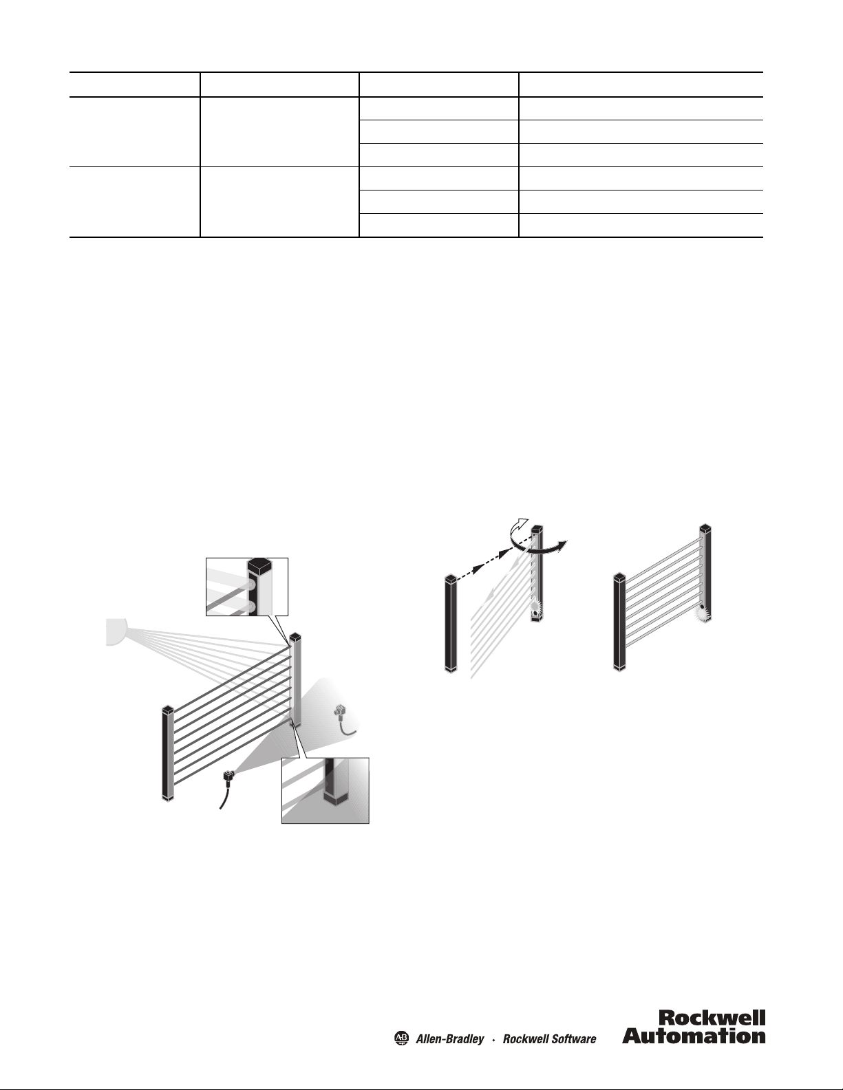
Alignment
This is a crucial step in the setup since sensor operation is
dependent on correct alignment of the emitter and receiver. This
process is simplified by using the green LED on the receiver unit
to serve as an indication of proper alignment.
Electrical Installation
Both light arrays must be connected to the controller through the
RJ45 connectors. For ease of connection, the pigtail connector for
the emitter has a white marker, and the receiver has a blue
marker. Be sure to connect the emitter to the plug connection on
the controller with the white marker, and the receiver to the plug
connection with a blue marker.
2
Horizontal Alignment
1. Aim the receiver 90° away from the emitter (light source) and
verify that the red status LEDs on both the receiver and emitter
are ON.
2. Slowly rotate the receiver to face the emitter and note the
point at which these red LEDs turn OFF and the green
alignment LED turns ON.
3. Continue to rotate the receiver away from the emitter until the
green LED turns OFF again, and the red LEDs turn ON. Note the
point at which this happens.
4. For horizontal centering, rotate the array halfway between the
two points at which the red LEDs turn OFF.
Page 3

3.2° 3.2°
The field of view of the 45MLA is 3.2°
Receiver Array
Emitter Array
45MLA Controller
Emitter connecting cable
Receiver connecting cable
For use in NFPA 79 applications only.IMPORTANT
32 (1.26)
28 (1.10)
M4
20
(0.79)
4.8
(0.19)
dia.
1.9
(0.08)
4.9
(0.19)
12.7
(0.50)
8.9
(0.35)
30
(1.18)
25.5
(1.00)
M4 x 16
3.3
(0.13)
3
(0.12)
Vertical Alignment
1. Beginning with the two arrays parallel to each other, slide the
receiver down and note the point at which the red LEDs turn
ON on both arrays. This indicates that the receiver is no longer
in line with the emitter.
2. Slide the receiver back upwards until the red LEDs turn OFF
and the green LED on the receiver turns ON. This indicates that
the two arrays are aligned.
3. Continue to slide the receiver upwards, noting the point at
which the green LED turns OFF, and the two red LEDs turn ON,
again indicating misalignment.
4. For vertical centering, position the receiver halfway between
the two points at which the red LEDs turn OFF.
Wiring Diagram
The 45MLA is a “Three Box System”—every setup consists of an
emitter array, a receiver array, and an external controller.
All electrical connections are made via the 45MLA-CTRL
controller.
Note: Cascading light array systems can consist of two or three
light array pairs. The last pair must be a standard array pair
and the first (and middle) pairs must be cascadable. A
total system can be no more than 10 m (32.8 ft) in length
from the controller to the end of the last array and cannot
exceed 254 total beams.
Adjustable Bracket 445L-AF6143
(4 pieces included) [mm (in.)]
(0.95)
18.9
(0.74)
15
6
(0.59)
(0.24)
5.5 (0.22)
38.7
(1.53)
18.7
(0.73)
24
M4 x 16
(0.11)
2.8
52
(2.05)
30
(1.18)
(0.84)
18.7
(0.73)
21.4
The 45MLA arrays feature an M12, 8-pin female QD which
connects to the connecting cable 445L-AC9RJx (x = 3, 5, or 8
meter length). The other end of the 445L connecting cable has an
RJ45 connector which plugs into the ports on the controller. The
emitter plugs into the top port, marked with the white dot. The
receiver plugs into the lower port, marked with the blue dot. The
445L connecting cable comes with both blue and white markers
at each end. It is recommended to remove the markers that do
not correspond to the array pigtail marker.
3
Flat Bracket 445L-AF6145 (sold separately) [mm (in.)]
Cascadable Array Extension Patchcord 445L-AC8PCx
Length, 1 or 3 m (3.28 or 9.8 ft); tolerance 0/+50 mm
80
50.2
(1.98)
17
(0.67)
Dia.
32.2
(1.27)
(3.15)
51.3
(2.02)
15 (0.59)
Dia.
Page 4

Dimensions [mm (in.)]
B
A
C
8-pin female
M12 (micro) QD
Cable clip 6 mm
White (emitter)
Blue (receiver)
0.75
(0.03)
18.5
(0.73)
8.1
(0.32)
500
(19.7)
0.75
(0.03)
1.5
(0.06)
20
(0.79)
15.8
(0.62)
B
A
C
8-pin female
M12 (micro) QD
Cable clip 6 mm
White (emitter)
Blue (receiver)
0.75
(0.03)
18.5
(0.73)
8.1
(0.32)
500
(19.7)
0.75
(0.03)
14.2
(0.56)
50
(1.97)
32.5
(1.28)
18.5
(0.73)
8.1
(0.32)
500
(19.7)
8-pin male
M12 (micro) QD
Cable clip 6 mm
White (emitter)
Blue (receiver)
Standard Array
Cascadable Array
Standard Array
A
Sensing Height [mm (in.)]
Housing Height [mm (in.)] Beam Spacing [mm (in.)] No. of Beams Cat. No.
C
300 (11.8) 322 (12.7) 25 (0.98) 12 45MLA-AT0300P25
600 (23.6) 622 (24.5) 25 (0.98) 24 45MLA-AT0600P25
900 (35.4) 922 (36.3) 25 (0.98) 36 45MLA-AT0900P25
1200 (47.2) 1222 (48.1) 25 (0.98) 48 45MLA-AT1200P25
300 (11.8) 322 (12.7) 10 (0.39) 30 45MLA-AT0300P10
600 (23.6) 622 (24.5) 10 (0.39) 60 45MLA-AT0600P10
900 (35.4) 922 (36.3) 10 (0.39) 90 45MLA-AT0900P10
1200 (47.2) 1222 (48.1) 10 (0.39) 120 45MLA-AT1200P10
Cascadable Array
A
Sensing Height [mm (in.)]
Housing Height [mm (in.)] Beam Spacing [mm (in.)] No. of Beams Cat. No.
C
300 (11.8) 339 (13.3) 25 (0.98) 12 45MLA-CT0300P25
600 (23.6) 639 (25.2) 25 (0.98) 24 45MLA-CT0600P25
900 (35.4) 939 (37.0) 25 (0.98) 36 45MLA-CT0900P25
1200 (47.2) 1239 (48.8) 25 (0.98) 48 45MLA-CT1200P25
300 (11.8) 339 (13.3) 10 (0.39) 30 45MLA-CT0300P10
600 (23.6) 639 (25.2) 10 (0.39) 60 45MLA-CT0600P10
900 (35.4) 939 (37.0) 10 (0.39) 90 45MLA-CT0900P10
1200 (47.2) 1239 (48.8) 10 (0.39) 120 45MLA-CT1200P10
Note: The 45MLA ships as a transmitted beam pair—both the emitter and receiver arrays are in one package. The “T” in the cat. no.
represents the transmitted beam pair. For individual parts, replace the “T” with an “E” for emitter or “R” for receiver, for example,
45MLA-AR0300P10.
August 2010, Printed in Switzerland
10000035051
107 863
 Loading...