

Page 1
45LUM Luminescence Sensor
IMPORTANT
Installation Instructions
Original instructions in English
Specifications
SAVE THESE INSTRUCTIONS FOR FUTURE USE.
Description
The 45LUM Luminescence sensor provides a solution for detection of
substances which are invisible to the human eye. This sensor detects
lumiphors or flourescents which are emitted from the object being
detected. The sensor converts the UV light into a visible light, which is
then received by the luminescence sensor. This sensor can detect
particles such as glue, clear labels, oils, greases, paint, detergents, and
chalks.
The 45LUM contains a teach button to simplify the setup process and
even provides the option to remote teach the sensor. The sensor has
one discrete output which is light operate (L.O.) and it contains a small
light spot for accurate positioning. The sensor contains a rotatable
plug and is also offered with various mounting accessories to ease
installation.
The 45LUM sensor is an excellent solution to a broad range of
applications including industries such as automotive, packaging,
material handling, and food and beverage. Flourescent/lumiphores in
an object can be easily detected, however, flourescents/lumiphores
can also be added to a material and not affect the original product.
Features
• Sensing range of 5…50 mm (0.2…2 in.)
• Detection of luminescence/flourescent particles and materials
• Easy setup of switch points using teach button
• External teach capability
• Rotatable plug for flexibility during installation
• IP67 enclosure
• Self-contained sensor
Cert ification s UL, cU Lus, and CE Marked for all applicable directives
Enclosure Type Rating IP67
Operating Temperature [C(F)] -10…+55° (+14…+131)
Storage Temperature [C(F)] -20…+80° (-4…+176)
Vibration 10…55 Hz, 1 mm amplitude, meets or exceeds IEC 60947-5-2
Shock
Optical
Sensing Range 5…50 mm (0.2…2.0)
Light Source Visible ultraviolet LED
Indicator LEDs
Electrical
Operating Voltage 12…28V DC
No Load Supply Current ≤ 40 mA
Protection Type Class 2 protection, short circuit, reverse polarity
Outputs
Response Time 1 ms
Output Type PNP, N.O., light operate
Output Function Light operation for discrete output
Output Current ≤ 100 mA
Switching Frequency 500 Hz
Mechanical
Housing Material ABS
Lens Material Glass
Connection Type 5-pin DC micro (M12) QD, rotatable
30 g with 11 ms pulse duration, meets or exceeds
IEC 60947-5-2
Green: Power and mode; Yellow: Object detected/switching
output active
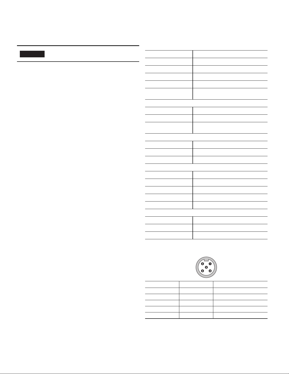
Pinout and Color Codes
Pin Color Connection
1Brown V+ 12…28V DC
2 White Input (remote teach)
3Blue V- 0V DC
4Black Output
5Grey Teach button lock
Rockwell Automation 45LUM-IN001A-EN-P — May 2014
Page 2
2 45LUM Luminescence Sensor
50
(1.97)
50
(1.97)
4
(0.16)
4.3
(0.17)
4.3
(0.17)
4
(0.16)
Teach instructions
1. Push set 3 seconds
yellow LED on
2. Place object in front
of sensor
3. Push set 1 second
yellow and green
LED on
46
(1.81)
44
(1.73)
16
(0.63)
13.5
(0.53)
4
(0.16)
40 (1.58)
44 (1.73)
M12x1
17
(0.67)
1
+U
B
BN
3
BU
5
GY
4
BK
2
WH
IN ET
-U
B
Q
Lock
SET button to teach sensor
Yellow LED output indicator
Green LED signal indicator
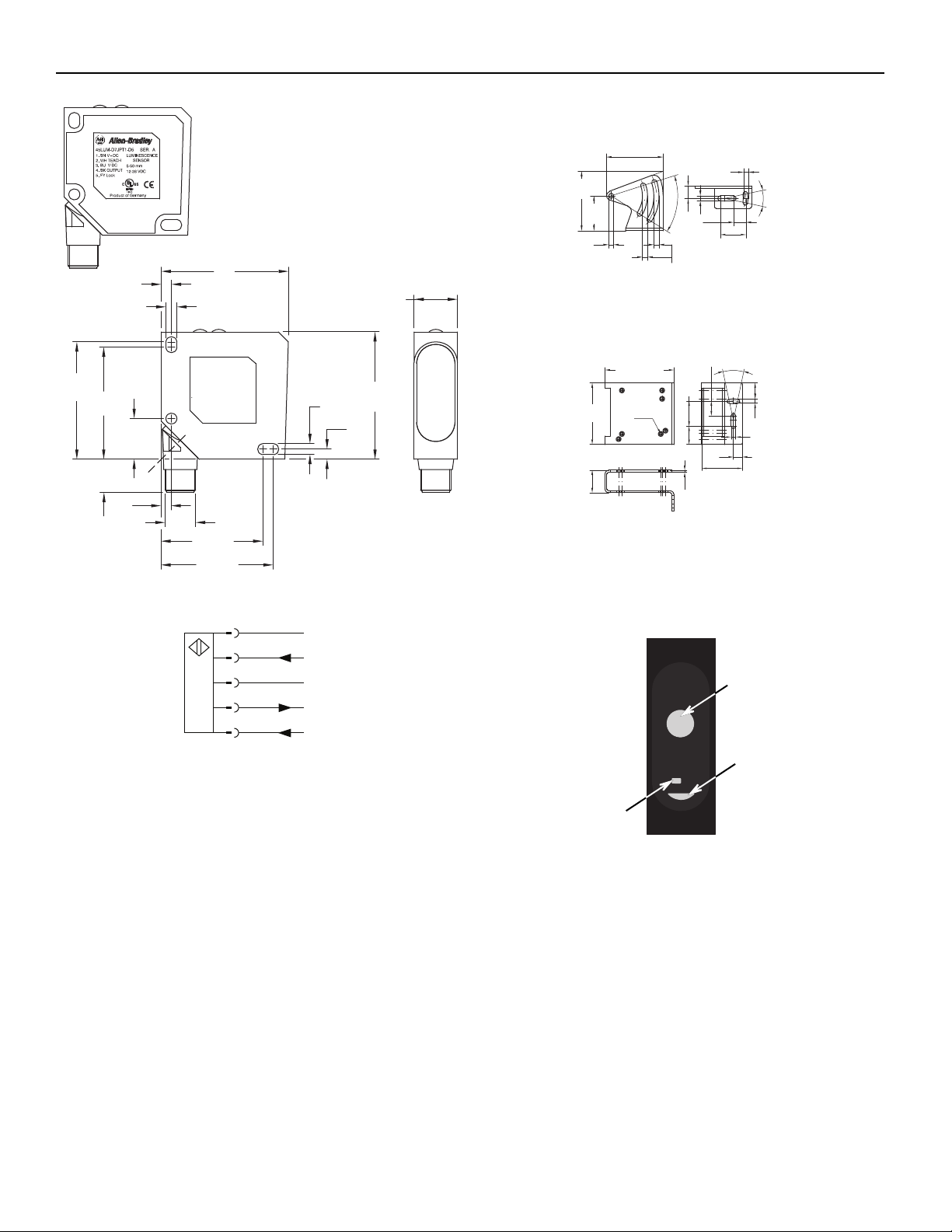
Dimensions [mm (in.)]
Mounting [mm (in.)]
45BPD-BKT1
Wiring Diagrams
50.97
(2.0)
(0.165)
(1.18)
4.2
48.5 (1.9)
30
4.3
(0.169)
50°
10.5
(0.41)
4.3 (0.169)
24°
10.5 (0.41)
22 (0.86)
4.3 (0.169)
45BPD-BKT2 (protective bracket)
13.9
(0.54)
24°
14.85 (0.58)
4.3 (0.169)
4.3
(0.169)
8.5
(0.33)
38.2 (1.5)
2
21.2
(0.83)
58
(2.28)
65 (2.55)
7 x M4
23.8
(0.93)
17
(0.66)
(0.07)
Teach Interface
How to teach the sensor
1. Familiarize yourself with the LED indicator and teach button.
SET
Teach
Output
2. The sensing distance of the 45LUM is 5…50 mm (0.20…2.0 in.).
3. Position the target in front of sensor.
4. The optimal distance is 18 mm (0.71 in.).
5. Push the SET button for three seconds — the green and yellow
LEDs will turn on.
6. Push the SET button for one second — the yellow and green LEDs
will turn on. The teach setup is complete.
Rockwell Automation 45LUM-IN001A-EN-P — May 2014
Page 3

Maximum Range/Sensitivity
It is possible to configure the sensor for maximum sensitivity by
following these steps:
1. Position the sensor so that there is not target in range (nothing
closer than 50 mm).
2. Push SET for three seconds. The green and yellow LEDs will turn
OFF.
3. Push SET for one second. The green LED will turn ON.
The teach setup is completed.
Push Button Lock and Unlock
Sensors with teach or manual adjustment are flexible and can be used
in many applications. However, some engineers do not like the idea of
an operator or maintenance person making changes to the settings of
a sensor after the initial setup. These engineers often ask for fixed
range sensors. Another potential solution is to prevent adjustment by
locking the teach button.
The push button on the 45LUM can be locked. A permanent lock can
be achieved by attaching the grey wire (pin 5) to V-. If the grey wire is
connected to V-, the push button is completely ignored by the sensor
and no changes can be made. By taking advantage of this feature, the
engineer originally applying the sensor can greatly reduce the
likelihood of the settings of the sensor later being changed.
45LUM Luminescence Sensor 3
Remote Teach
The sensor can be taught remotely via the white wire (pin 2).
Connection to +V acts the same as the button being pressed and no
connection is the same as the button not being pressed. The sensor
can be taught by following the same teach/timing sequence as used
in the push button teach (e.g., connect to the +V for more than three
seconds to teach the “target,” disconnect from the +V; remove the
target and connect to the +V for less than one second to teach the “no
target” condition. All push button functions can also be carried out via
RT.
1. Connect the white wire to V+ for more than three seconds (voltage
is greater than 12…28V).
2. Teach the sensor by placing the target in front of the sensor. The
sensing distance for 45LUM is 5…50 mm (0.2…2 in.).
3. Disconnect the white wire from V+.
Rockwell Automation 45LUM-IN001A-EN-P — May 2014
Page 4

4 45LUM Luminescence Sensor
Rockwell Automation maintains current product environmental information on its website at
http://www.rockwellautomation.com/rockwellautomation/about-us/sustainability-ethics/product-environmental-c ompliance.page
Allen-Bradley and Rockwell Automation are trademarks of Rockwell Automation, Inc. Trademarks not belonging to Rockwell Automation are property of their respective companies.
Copyright © 2014 Rockwell Automation, Inc. All rights reserved. Printed in the USA.
Publication 45LUM-IN001-EN-P — May 2014 — 10000954687 Ver 00
068-14552
 Loading...