

Page 1

Installation and Operating Instructions
Bulletin 45LSP Optical Fork PHOTOSWITCHr Photoelectric Sensors
IMPORTANT: SAVE THESE INSTRUCTIONS FOR FUTURE USE.
Refer to the product catalog pages for additional information.
Description
The 45LSP is a family of optical fork sensors hous ed in a
plastic enclosure. Fork sensors offer self-contained
transmitted beam sensing, ideal for applications that require
reliable parts detection. A simple push button teach-in
sensitivity adjustment, several connection options and
multiple mounting features (via s ide thru-holes, rear threaded
inserts or optional dovetail bracketry) mak e the 45LSP an
economical, easy-to-use solution for typical applications such
as small part detection, edge detection, part counting, gear
tooth detection and dimension v erification.
Features
S Detection of objects as small as 0.2 mm (0.0078 in.)
S Highly visible power and output LED indicators with output
indication along both sides of the fork
S Remote teach and teach button lock on 4-pin models
S Light or dark operate selec table
S Multiple mounting options: thru-holes, threaded holes and
dovetail
S Easy installation with no alignment required
S IP67 enclosure
User Interface
LED Color State Status
OFF Output de-energized
Orange
Green
ON Output energized
Flashing Teach mode or short circuit
protection active
OFF Power is OFF
ON Power is ON
Flashing Teach mode
Specifications
Certifications cULus and CE Marked for all applicable directives
Optical
Sensing Gap 30 mm
Smallest Detectable
Target
Light Source Visible red (640 nm)
Sensitivity Adjustment Teach button and remote teach
Electrical
Voltage 10…30 V DC
Current Consumption 30 mA max.
Protection Reverse polarity and short circuit
Outputs
Response Time 250 µs
Output Type PNP or NPN
Output Mode Light or dark operate selectable
Output Current 100 mA max.
Mechanical
Housing Material Polycarbonate
Connection Types 3-pin pico QD, 4-pin pico QD
Optional Accessories 44B-BKT dovetail mounting bracket and cordsets
Environmental
Environmental Rating IP67
Operating Temperature -10…+60 °C(14…140 °F)
For detection of objects less than 0.9 mm (0.035 in.), the object should be placed ≥10 mm
(0.39 in.) away from the LED light source.
(1.18 in.)
0.2 mm
(0.07 in.)
Teach button
50 mm
(1.97 in.)
0.2 mm (0.007 in.) 0.4 mm
80 mm
(3.15 in.)
Green LED
120 mm
(4.72 in.)
(0.02 in.)
Orange LED
Orange LED
1
Page 2
Operation Instructions
Sensitivity Adjustment
With no target present, press the teach button for
approximately three seconds until orange LEDs are flashing
synchronously: first thres hold is taught. With the target
present, press the teach button for approximately one
second. If the green LED flashes and stays on then
thresholds have been taught, and the sensor is ready to
operate. If both LEDs are flashing synchronously then the
sensor cannot detect the object and no thresholds have been
taught.
Sensitivity Adjustment During a Running Process (optimum detection
of very small parts)
With the chosen running proc ess being the only thing in the
scanning area, press the teach button for approximately three
seconds until orange LEDs are flashing synchronously. Press
the teach button until a minimum of one process cycle is
completed. If the green LED flashes and stays on then
thresholds have been taught, and the sensor is ready to
operate. If both LEDs are flashing synchronously then the
sensor cannot detect the target and no thresholds hav e been
taught.
L.O./D.O. Setup
Press the teach button for approximately 13 seconds. Orange
LEDs should flash alternately. When you release the button,
the green LED should remain flashing. When the green LED
is flashing, the output is inverted by pressing the button. The
orange LED shows active function. Do not press the button
for 10 seconds. The green LED stops flashing and the
present output function is saved. The sensor is ready to
operate.
Maximum Sensitivity
With no target present, press the teach button for
approximately three seconds until orange LEDs are flashing
synchronously. Again, with no target present, press the teach
button for one second. The sensor is set to maximum
sensitivity and is ready to operate.
Maximum Stability—Fa ctory Setting (max. resistance to
contamination)
Cover the light source. Press and hold the teac h button until
the orange LEDs are flas hing synchronous ly. Keep the light
source covered, press the teach button for one second. The
sensor is set to maximum stability and is ready to operate.
Modification of the Emitter Frequency in Case of Mutual Interference
Switch one sensor off. Press the teach button during power
ON. The orange LED flashes one time; frequency one,
normal operation (switching frequency 2 kH z). Keep the
button pressed for another three to five seconds. The orange
LED flashes twice; frequency two, normal operation
(switching frequency 2 kHz). Keep the button pressed for
another three to five seconds. The orange LED flashes three
times; frequency one, detection of very small parts possible
(switching frequency 2 kHz). Keep the button pressed for
another three to five seconds. The orange LED flashes four
times; frequency two, detection of very small parts possible
(switching frequency 1.5 kHz). Release the button to place
the sensor in operating mode. Switch other sensor on again.
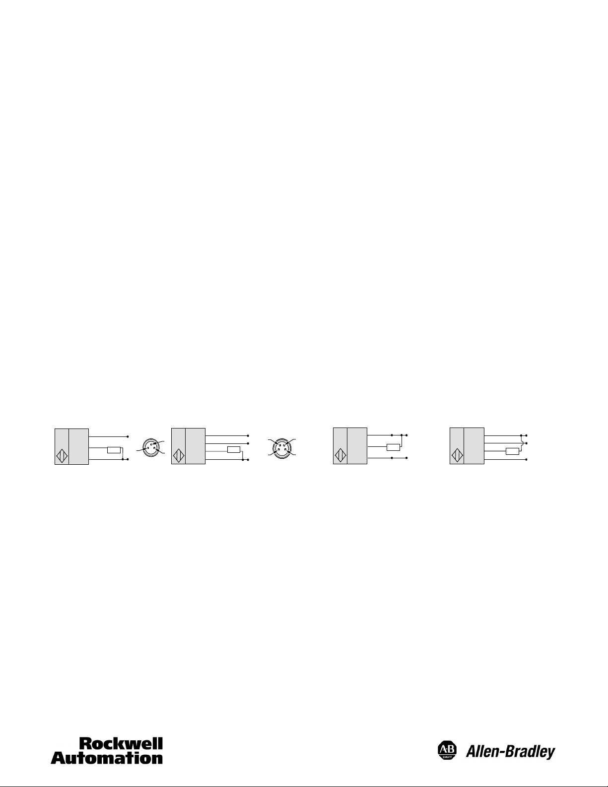
Wiring
3-Pin
Remote teach.
Brown (1)
Black (4)
Blue (3)
Load
NPN ModelsPNP Models
4-Pin 3-Pin 4-Pin
+
1
–
4
3
Brown (1)
White (2)
Black (4)
Blue (3)
Load
+
2
1
–
4
3
Brown (1)
Black (4)
Blue (3)
+
Load
–
Brown (1)
White (2)
Black (4)
Blue (3)
Load
+
–
2
Page 3

Approximate Dimensions [mm (in.)]
GF
B
A
10
(0.39)
12 (0.47)
4
4.2 (0.17) 3x Dia.
C
D
E
4.5 (0.18)
8 (0.31)
Teach-in
button
5
(0.2)
4.5 (0.18)
Fork Type A B C D E F G H I
30 mm 30 (1.18) 50 (1.97) 30 (1.18) 34 (1.34) 59.5 (2.34) 20 (0.78) — 62.2 (2.45) 71.7 (2.82)
50 mm 50 (1.97) 70 (2.76) 50 (1.97) 54 (2.13) 79.5 (3.13) 20 (0.78) 28 (1.10) 82.2 (3.24) 91.7 (3.61)
80 mm 80 (3.15) 100 (3.93) 80 (3.15) 54 (2.13) 79.5 (3.13) 20 (0.78) 2 x 28 (2.20) 112.2 (4.42) 91.7 (3.61)
120 mm 120 (4.72) 140 (5.51) 120 (4.72) 54 (2.13) 79.5 (3.13) 20 (0.78) 3 x 28 (3.30) 152.2 (5.99) 91.7 (3.61)
Optional Accessories
Description Cat. No.
Dovetail mounting bracket 44B-BKT
2m(6.5ft)3-pinDCpicoQD 889P--F3AB--2
2m(6.5ft)4-pinDCpicoQD 889P--F4AB--2
3
Page 4

10000033147 Ver 01
January 19, 2009
Printed in USA
4
 Loading...