

Page 1
Installation Instructions
PHOTOSWITCHr Bulletin 45LFM Label Sensor
IMPORTANT: SAVE THESE INSTRUCTIONS FOR FUTURE USE.
Description
The Rockwell Automation 45LFM–CMBA1–D5 Label Sensor
is an innovative electronic sensor used to sense and/or count
labels. A signal is generated as the edge of the label passes
through the sensor. It can be configured to sense the leading
or trailing edge.
Features
S Consistently senses the presence of most labels on a web
S Clear labels on clear backing
S Clear labels on opaque backing
S Opaque labels on clear backing
S Opaque labels on opaque backing
S Count 50,000 labels per minute with registration error less
than 0.01 inch
S Heavy-duty metal housing
S Ideal for label counting and label registering applications
Specifications
Supply Voltage &
Current
Power-Up or Reset
Leakage Current 5µA
Output Configuration Complimentary: NPN and PNP
Output Rating 150mA max
Short Circuit Protection Yes
Reverse Polarity
Protection
Output Invert Control Yes
Registration Accuracy 0.025mm (0.01in)
Response Time 10microseconds
Maximum Switching
Minimum Gap or
Label Size
Indicators Edge, zero
Construction Anodized aluminum
Environmental Rating IP54
Connections 5Ćpin micro QD
Operating Conditions
Approvals CE marked for all applicable directives
11 to 30V DC @ 50 mA max
10microseconds
Delay
Yes
10KHz
Speed
0.76mm (0.03in)
4_C to 50_C (40_F to 120_F)
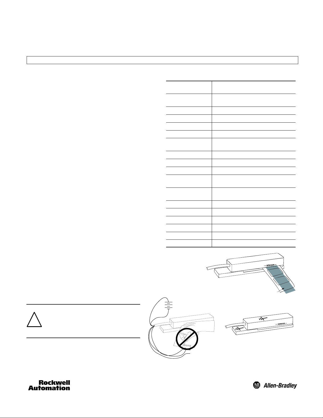
Mounting the Sensor
Mount the sensor perpendicular to the web so the web
passes through the sensor gap. The back of the web should
contact the mounting plate. Labels must pass under sensing
area marked [––SENSOR––]. Small labels (38.1mm (1.5in))
must be centered under the sensing area.
Electrical Connections
ATTENTION: Unused wires must be
insulated from contact with other
objects. All power must be off when
!
installing the sensor. DC ground is
connected to sensor body.
No power during
connection.
Labels must pass under Sensor.
Sensing Area
Sensor case is
grounded
Page 2
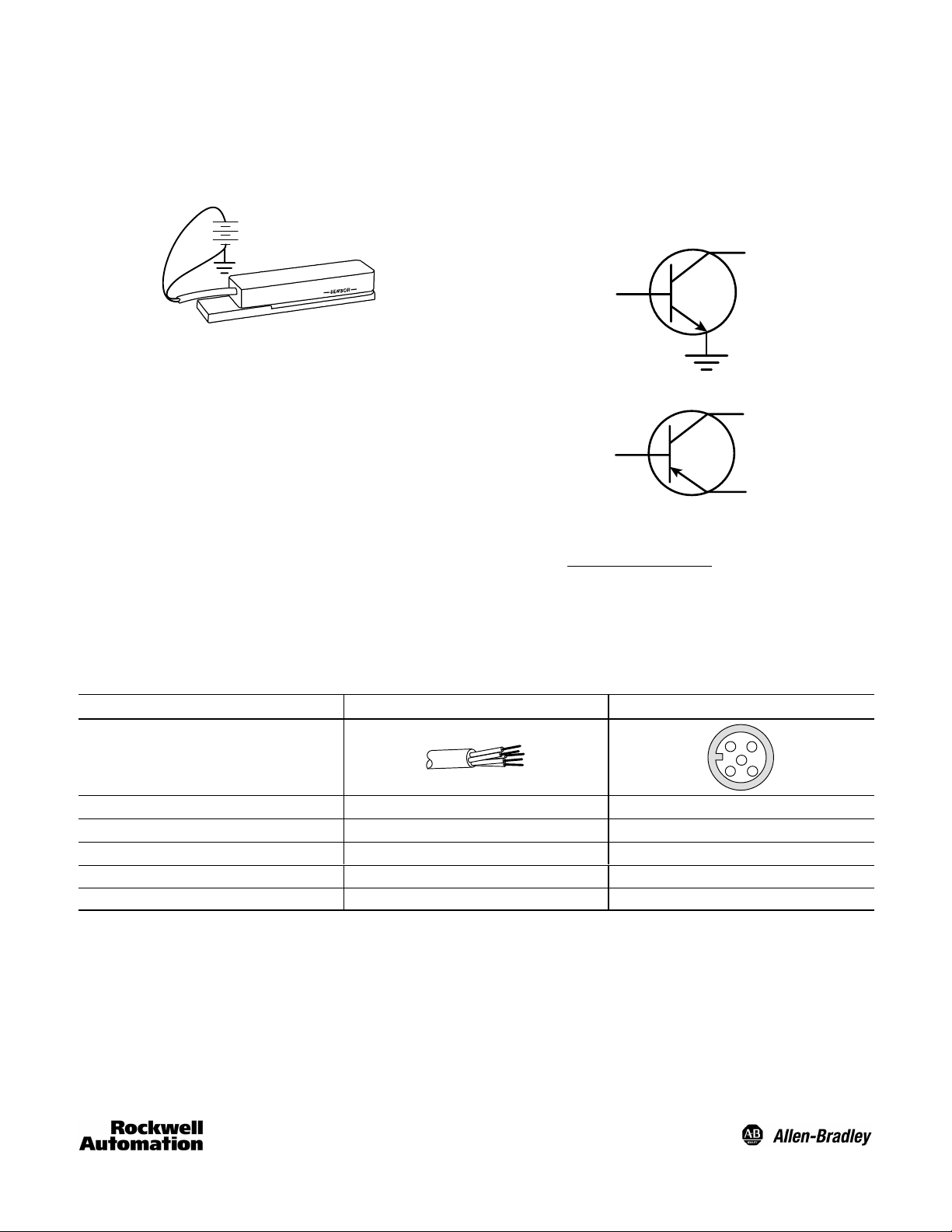
Power
Sensor can be powered with 11–30V DC but optimum
performance is obtained with 24V DC. The negative side of
the power supply is grounded to the sensor body.
+Vin 24V DC
(11-30V DC)
50mA
Outputs
The NPN and PNP outputs are open-collector outputs. The
NPN output can sink up to 150mA and the PNP output can
source up to 150mA. Outputs are short circuit protected by
self-resetting internal fuses. These fuses will activate if the
outputs are connected directly to ground or power. Repeated
shorting will eventually cause the sensor to fail.
NPN Output
150mA maximum
PNP Output
150mA maximum
PNP Power In
+Vin maximum
(+30V DC)
The PNP POWER IN voltage must be connected to a supply
voltage and must not exceed +Vin
(+30V DC).
Output Polarity
Output polarity determines whether the output signal will go low or high on the label edge.
Note: Output polarity also depends on the direction of label movement through the sensor (see figure on page 4).
Wiring Table
Designation Lead Color (Cordset) 5ĆPin Micro QD Pin Assignment
Termination
V+ Brown 1
0V Blue 2
PNP Output/150mA maximum Black 3
NPN Output/+30V DC/150mA maximum White 4
Output Polarity/Ground or +Vin Grey 5
4
2
5
3
1
2
Page 3

Adjusting Gain and Zero
These sensors are extremely stable and should not require adjustment after the initial setup. Adjustment will only be required
for significant changes in label shape or thickness, or changes in power supply voltage.
1. Remove all material from sensor.
2. Center GAIN ADJUST
Turn GAIN ADJUST four
(4) turns counter clockwise.
Turn GAIN ADJUST two
(2) turns clockwise.
3. Set ZERO ADJUST
Set ZERO ADJUST to the
point where the ZERO light
starts to come on.
4. Set GAIN ADJUST
Insert material into sensor.
While moving labels through
Flash start plus 1/2 turn
the sensor, Set GAIN ADJUST
to the point where the EDGE
light starts to flash. Then
continue turning 1/2 turn
clockwise.
5. Sensor is now ready for use.
How GAIN and ZERO adjustments affect the 45LFM–CMBA1–D5
The 45LFM–CMBA1–D5 is a dual capacitor type sensor.
Labels pass or move in the direction from C1 to C2 or vise
versa. The common plate of both capacitors is the base plate
that makes up the c-frame of the sensor. The electronics in
the sensor measure the difference between C1 and C2,
analog voltage = C1 – C2, which makes this sensor a
differential type sensor.
C1 C2
Base plate of
45LFM-CMBA1-D5
When common material, web and label, is under both plates
C1 = C2 and the internal analog signal is 0 Volts. Also when
nothing is place in the sensor C1 = C2. When you press on
the BASE PLATE of 45LFM–CMBA1–D5 sensor and change
the gap of the sensor C1, for the most part, = C2. As material,
web and labels, pass through the sensor, it is the fact that the
gap of the label goes under C1 first that causes the analog
voltage to increase. Once the gap of the label is between C1
and C2 and common material is again under both capacitors,
the analog voltage returns to 0V. As the gap of the label
passes under C2, the analog voltage decreases. As common
material returns under both capacitors the analog voltage
returns to 0V. This 0V is the internal supply voltage and is not
the 0V supplying the power to the sensor.
3
Page 4

The gain adjustment is required in order to be sure the analog
)
3
A
voltage goes beyond two trip points. The first trip point is a
positive voltage point and turns the output on when the
analog voltage exceeds the trip voltage. While the second trip
point is a negative voltage point and turns the output off when
the analog voltage goes below the negative trip voltage.
Things that affect gain are: size of labels, both thickness and
width, and power supply voltage. Powering the sensor with
12V requires increased gain than when powering the sensor
with 24V. Thinner labels also require more gain for proper
detection. Too much gain can cause the sensor to pick up
certain types of ink on the label and cause false detection.
Output Polarity and Signal Waveforms
Output polarity is effected by the direction of label movement. Waveforms shown are for label movement shown in diagram.
Reversing label direction will invert waveforms.
Output Output Polarity
NPN Ground
NPN +Vin
PNP Ground
PNP +Vin
Dimensions—mm (inches)
M4 x 17.7
(0.7) (x4)
20.3
(0.8)
5.1
(0.2)
7.6
(0.3)
25.4
(1.0)
15.2
(0.6)
140 (5.5)
30.5
(1.2)
SENSOR
31.8
(1.25)
24.1
(0.95)
15.2
(0.6)
Gap 0.76 (0.03)
(Adjustable)
PHOTOSWITCHR is a registered trademark of
Rockwell Automation.
4
Publication 75009–193–01(A
January 200
Printed in US
 Loading...