

Page 1
Installation Instructions
PHOTOSWITCHr Bulletin 45FVL Digital SelfĆTeaching Fiber Optic
IMPORTANT: SAVE THESE INSTRUCTIONS FOR FUTURE USE.
Product Description
The 45FVL is a DIN rail mountable fiber optic photoelectric
sensor with sophisticated detection, diagnostic and self-teach
capabilities. Possible modes of sensing include transmitted
beam, diffuse and retroreflective, allowing the 45FVL to be
used in a variety of complex applications.
Summary of 45FVL Features
S Self-teach capability—Allows the 45FVL photoelectric
sensor to determine an optimum sensitivity and hysteresis
setting for a specific application.
S Manual or automatic sensitivity adjustment.
S Back-Lit LCD Display. Clearly displays various operating
modes, functions and diagnostic information.
S Visible red, green, white, or blue light source.
S Selectable 40ms off delay output timer. “Pulse stretcher”
useful in high speed applications when the output pulse
must be lengthened to allow time for the machine logic to
respond.
S DIN rail mountable. For installation convenience, a steel
bracket is supplied for specific mounting requirements.
S “Power Bus” option. Interface which allows user to
jumper power on several DIN rail mounted units to reduce
unnecessary wiring.
S Dual channel interference protection. Prevents crosstalk
between 2 sensors.
S Short circuit protection.
S Reverse polarity protection.
S False pulse protection.
S Transient noise protection.
The 45FVL photoelectric sensors are designed for use with
plastic fiber optic cables up to 2.2mm diameter. An adaptor is
supplied with the sensor for use with 1.25mm diameter plastic
fiber optic cables. No tools are required to attach or remove
fiber optic cables. Special glass fiber optic cables are also
available.
Accessories
S Mounting Bracket : Quantity 1
S Instruction Manual : Quantity 1
S Fiber Adaptor : Quantity 1
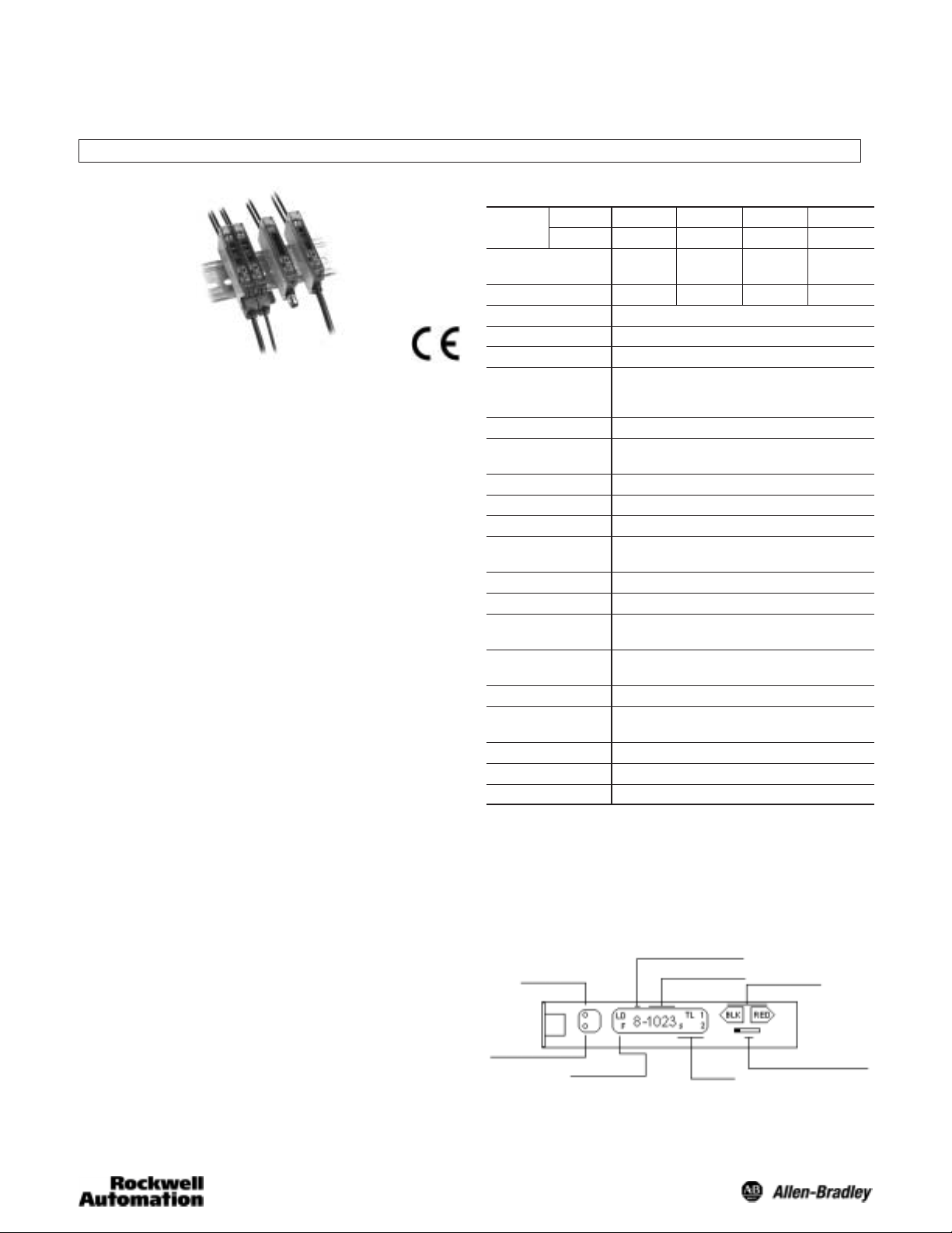
General Specifications
NPN Type
Model
PNP Type
Light Source Red LED Green
(Wave Length) (660nm) (565nm) (470nm) Ċ
Power Supply 12 to 24V DC +/- 10% Ripple 10% or Less
Current Consumption NPN Type: <39ma/PNP Type: <50ma
Output Mode Open Collector
Operation Mode Light On/Dark On Selectable
Output Timer Off delay/Nondelay Selectable
Indicators Orange LED = Output, Green LED = Power/Stability
Response Time Channel 1 = 600µs, Channel 2 = 700µs
Interference Protection Yes
Short Circuit
Protection
Features Power bus for easy wireless power distribution
Material Polycarbonate
Operating
Temperature
Operating Humidity 35% to 85% RH
Operating
Environment
Vibration 10-55Hz
Approvals CE
45FVL-2LG 45FVL-3LG 45FVL-6LG 45FVL-5LG
45FVL-2LH 45FVL-3LH 45FVL-6LH 45FVL-5LH
Blue LED White LED
LED
Range Depends on Fiber
NPN Rated: 100ma @ 30V DC Max, <1V Residual
PNP Rated: 100ma @ 30V DC Max, <2V Residual
Delay time: 40ms fixed
Yes
Wiring Cable 2m (6.5ft) or 4Ćpin pico QD connector or Power
Bus QD connector
-25_C to +55_C (-13_F to 131_F)
NEMA 1, IP 40
Shock 50g
User Interface
The user interface contains a back lit LCD display, two
adjustment buttons, operation selector switch, and LED
indicators for configuring and viewing the sensor’s operation
and status. A more complete description of each item is
described below.
Stability Indicator
(Green LED)
Output Indicator
(Orange LED)
Operating Modes
L: Light On
D: Dark On
F: Off Delay
Sensitivity Level (1, 2, ...8)
Incoming Light Level
+
RUN
Functions
L: Locked Mode
S: Sensitivity Adjustment Status
T: Teach Mode
Push Buttons
-
SET
Operation Selector Switch
Page 2
Sensor Selection
C
Output: 100ma
+/ 10%
Output Characteristics Catalog Number
Operating
Voltage
12-24V DC
+/- 10%
Ê PowerBus master/3 conductor QD = 45F–A3C–A2. PowerBus slave/1 conductor QD = 45F–A1C–A2
Current
Consumption
50ma or Less PNP
39ma or Less NPN
Type
Max Load
Current
Output: 100ma
Stability: 50ma
Max Leakage
Current
0.5ma 600µs
Response
Time
LED
Red 45FVL-2LHE-A2 45FVL-2LHE-P4
Green 45FVL-3LHE-A2 45FVL-3LHE-P4
Blue 45FVL-6LHE-A2 45FVL-6LHE-P4
White 45FVL-5LHE-A2 45FVL-5LHE-P4
Red 45FVL-2LGE-A2 45FVL-2LGE-P4
Green 45FVL-3LGE-A2 45FVL-3LGE-P4
Blue 45FVL-6LGE-A2 45FVL-6LGE-P4
White 45FVL-5LGE-A2 45FVL-5LGE-P4
Cable Pico
Power Bus
(QD required)
45FVL-2LHE-C4 Ê
45FVL-3LHE-C4 Ê
45FVL-6LHE-C4 Ê
45FVL-5LHE-C4 Ê
45FVL-2LGE-C4 Ê
45FVL-3LGE-C4 Ê
45FVL-6LGE-C4 Ê
45FVL-5LGE-C4 Ê
Output and Stability Indicators
Two LEDs (green and orange) indicate a variety of conditions
to facilitate set-up and troubleshooting. The function of each is
described in the table below. Relevant output and stability
data are also shown.
LED State Condition
Green
Orange
OFF
ON
OFF
ON
Operation Indicator and Stability Indicator
Light on operation
Stable range level
On level
Off level
Unstable range level
Light level
Output
Operation
Indicator
Stability
Indicator
Stable range
(light interrupted)
Dark on operation
Stable range level
Off level
On level
Unstable range level
Light level
Output
Operation
Indicator
Stability
Indicator
Stable range
(light interrupted)
Unstable range
Unstable range
Unstable range
Unstable range
Stable range
On
On
On
Stable range
(light on)
On
On
On
(light on)
Unstable light signal
Stable light signal
Output OFF
Output ON
Unstable range
Unstable range
OnOn
Stable range
(light interrupted)
OnOn
Stable range
(light interrupted)
Operation Selector Switch
When the selector switch is in the RUN position (see following
example), the sensor will function normally, and all settings
are locked from adjustment. The SET position unlocks the
sensor’s settings, allowing the user to either adjust the sensor
manually, or use the self-teach functionality. When
adjustments are complete, return the switch to the RUN
position (settings become locked). If a manual sensitivity
adjustment is required a user can unlock this setting by
(quickly) switching from RUN to SET to RUN. The sensor will
display a flashing “S” on the LCD display, and the user can
now adjust the sensitivity setting. The sensor will automatically
return to the locked condition 10 seconds after sensitivity
adjustment is complete.
Locking
Two Adjustment Buttons
The red button is used to teach the sensor, change the
frequency and to increase the sensitivity.
The black button is used to change the operating mode,
indication mode and to decrease sensitivity.
Both buttons are inactive in the RUN mode.
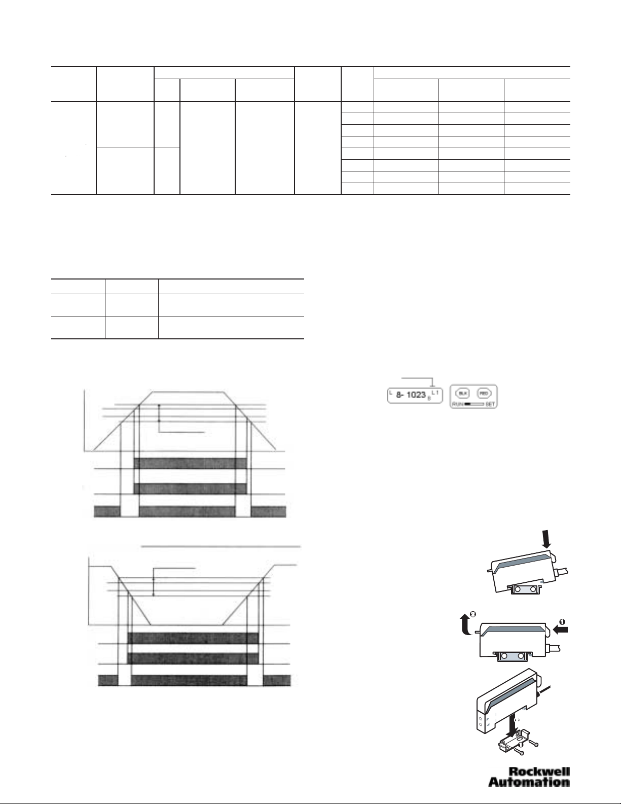
Mounting the Sensor
How to Attach Sensor to DIN Rail
Attach front hook of the photoelectric
sensor onto rail (or Mounting bracket)
and press rear end of sensor down
until unit snaps into place.
How to Detach Sensor from DIN Rail
Pushing the sensor unit forward,
pull up on the front of the sensor
until the front hook is detached.
Remove sensor.
Side Mounting Sensor with Bracket
Fasten mounting bracket assembly
using M3 screws. Tightening torque is
0.8Nm max. Attach front hook of the
photoelectric sensor onto mounting
bracket and press rear end of sensor
down until unit snaps into place.
2
Page 3

Installing the Fiber Optic Cables
S Push down the locking lever
S Insert fiber all the way
S Lift locking lever to lock fiber in
place
Maximum fiber insertion length is
13mm
For installation of smaller fiber
optic cables with jacket
diameters of 0.05mm (1.25in)
adaptors are provided for easy
installation.
Wiring the Sensor
Choice of Power Bus, 2m (6.5ft) cable, or 4 pin pico QD
connector are provided for wiring the 45FVL Series sensors.
On the pico QD models Rockwell Automation/Allen-Bradley
recommends the use of the 889 Series cordsets and
patchcords (i.e., 889P–F4AB–2). Standard 2m (6.5ft) cable
lengths are provided with flying leads for hard wiring. Hard
wiring color coding and pin assignment for QD connectors are
as specified below.
Lead Color
Designation
Termination
V+ Brown 1
0V Blue 3
Output Black 4
2m (6.5ft) Cable
Pin Assignment
4 Pin Pico QD
2
143
NPN Output
Brown
Black
Blue
Load
+
+-
-
PNP Output
Brown
Black
Blue
+-
Load
+
-
Configuring and Using the Sensor
This section will run through the basics on how to operate
your new 45FVL Series sensor. After connecting power, load,
and fiber optic cables the next step is to choose one of two
available options for your Display Mode: Absolute Sensing
Mode or Relative Sensing Mode.
Absolute Sensing Mode measures the absolute value of a
target’s reflected light at that moment represented in a fourdigit value ranging from 0 to 1023. Depending on the
reflectivity of the target 1 of 8 sensitivity level settings (with
1023 bits of resolution) is automatically chosen by the sensor
when target is taught. A “1,” representing the lowest sensitivity
level, would be displayed for a highly reflective target. A “8,”
representing the highest sensitivity, would be displayed for
dull, less reflective targets (see following diagram).
Sensitivity Level (Absolute sensing mode)
The Power Bus option utilizes PB quick disconnect cordsets
which are prewired with up to four conductors. When ganging
sensors with the Power Bus option a three conductor cordset
is wired to one sensor to provide power to all ganged units.
The remaining ganged units use a single conductor cordset
for wiring an output. This option eliminates two conductors per
ganged unit (see below).
Maximum number of
units paralleled: 16
Female
End Cap
Brown
+ V
- V
Blue
_
+
Output
Black
_
+
Output
Black
Black
Output
Male
End Cap
Incoming Light Level shown in 4 digits
Min = 0 Max = 1023
Relative Sensing Mode monitors and displays the variation
of light received relative to the standard value at which it was
learned. In this mode the sensor measures and learns the
level of light reflected from a target. However, this value is
registered as “0” on the display when target is taught and all
subsequent measurements are relative to that standard value
+/– 1023 bits.
This mode is beneficial in applications to obtain the detailed
light attenuation rate due to soil/damage on the fiber end. See
diagram below.
Relative Sensing Mode
Relative Incoming Light
Min = -1023 Max = +1023
Setting Indication Mode
S Slide set switch to SET. Note flashing “T” on display.
S Pushing and releasing the BLACK button will change the
display to alternately switch between Absolute Sensing or
Relative Sensing Mode (see above).
3
Page 4

S Choose desired mode and slide set switch to RUN (settings
are now locked).
Setting Output Mode
Output Mode Options: Light On
Light On Off delay (40ms delay)
Dark On
Dark On Off delay (40ms delay)
S Slide switch to SET position
S Press and hold BLACK button for 3 seconds
S The display will show “SELE”
Frequency/Channel Indicator
Operating Mode
S Push the BLACK button until desired output is set
Light On
Light On
Off Delay
Dark On
Dark On
Off Delay
Transmitted Beam Setting
S Set up opposing fibers
S Block light with target
S Slide switch to SET (flashing “T”)
S Push RED button twice
S Slide switch to RUN
S Setting is complete
Sensitivity Adjustment (Absolute Sensing Mode)
S Quickly flip switch from RUN to SET to RUN (“s” flashes to
show sensitivity adjustment status)
S Push RED button to decrease sensitivity
S Push BLACK button to increase sensitivity
S Unit automatically enters locked condition 10 seconds after
completion of adjustment
Sensitivity Adjustment (Relative Sensing Mode)
S Quickly flip switch from RUN to SET to RUN (“s” flashes to
show sensitivity adjustment status)
S Push BLACK button to decrease sensitivity
S Push RED button to increase sensitivity
S Unit automatically enters locked condition 10 seconds after
completion of adjustment
S Slide switch to RUN
Setting Interference Protection
S Slide switch to SET position
S Press and hold BLACK button for 3 seconds
S The display will show “SELE”
S Push the RED button to select Channel 1 or 2 for
transmission frequency selection for prevention of
interference between 2 sensors
S Set switch to RUN
Teaching the Sensor
Stationary Target
S Slide switch to SET (flashing “T”)
S Push and release RED button without target present
(Indicators flash to show standby status)
S Push and release RED button with target in position
(Flashing indicators stop flashing)
S Slide switch to RUN
S Setting is complete
Moving Target
S Slide switch to SET (flashing “T”)
S Push and hold RED button (Orange and Green LED
flashing alternately)
S While holding down RED button pass target in front of
sensor (LED flashing slows down)
S Release RED button when target finishes passing sensor
S Slide switch to RUN
S Setting is complete
Dimensions—mm (inches)
9
(0.35)
Receiver
Transmitter
5 (0.2)
(0.35)
4 (0.16)
9
30
(1.18)
4.7
(0.19)
3
(0.12)
2-3.2 (0.13)
Dia. hole
21 (0.83)
11.5
(0.45)
21 (0.83)
60 (2.36)
4 (0.16)
16
(0.63)
36.5 (1.44)
16
(0.63)
Mounting Bracket
2-3.2 (0.13) x 5.2
(0.2) oval hole
Replacement Parts
S Plastic Sensor Cover: PSC1
S Fiber Optic Cable (Diffuse/Retro): 99–94
S Fiber Optic Cable (Transmitted Beam): 99–90
S Pico QD Cordset: 889P–F4AB–2
S Power Bus QD Connectors:
1 Conductor: 45F–A1C–A2
3 Conductor: 45F–A3C–A2
S Power Bus End Caps:
Male Cap: 45F–AMC
Female Cap: 45F–AFC
S 1.25mm fiber optic adaptor: 61–6731
(0.12)
3
3
(0.12)
Cord
Bushing
4.8
(0.19)
Dia.
PHOTOSWITCHR is a registered trademark
of Rockwell Automation.
Publication 75009–138–01(B)
May 2002
Printed in USA
4
 Loading...