

Page 1
1
Einbauanleitung
(c)
Installation Instructions
Notice d'installation
Deutch /
Français
(b)
Description
The Cadet 3 is a positive mode, tongue operated interlock switch. It interlocks the guard to
the machine control system and ensures machine power is isolated and remains isolated
whilst the guard is open.
Beschreibung
Der Cadet 3 ist eine Sicherheitszuhaltung mit Zungenbetätigung. Er
verriegelt die Schutztür über das Steuersystem der Maschine und
gewährleistet, daß die Versorgungsspannung zur Maschine getrennt wird
und solange getrennt bleibt, wie die Schutztür geöffnet ist.
Description
Le Cadet 3 est une gâche électromagnétique à broche pour le verrouillage des
portes de machine. Il assure le verrouillage du système de commande de la
machine et ainsi que la mise hors tension, et le maintien hors tension, de la
machine tant que les portes de protection sont ouvertes.
RETAIN THESE INSTRUCTIONS
Installation must be in accordance with the following steps and must be
carried out by suitably competent personnel.
This device is intended to be part of the safety related control system of a
machine. Before installation, a risk assessment should be performed to
determine whether the specifications of this device are suitable for all
foreseeable operational and environmental characteristics of the machine to
which it is to be fitted.
At regular intervals during the life of the machine check whether these
characteristics foreseen remain valid and inspect this device for evidence of
accelerated wear, material degradation or tampering. If necessary the device
should be replaced . Guardmaster cannot accept responsibility for a failure of
this device if the procedures given in this sheet are not implemented or if it
is used outside the recommended specifications in this sheet.
The interlock is not to be used as a mechanical stop.
Guard stops and guides must be fitted.
Exposure to shock and/or vibration in excess of those stated in
IEC 68 part: 2-6/7 should be prevented.
Adherence to the recommended maintenance instructions forms part of the
warranty.
DIESE ANLEITUNG AUFBEWAHREN
Der Einbau muß durch einen entsprechend qualifizierten Mitarbeiter
erfolgen, und folgende Schritte müssen hierbei beachtet werden.
Dieses Gerät ist für den Einsatz als Teil des sicherheitsbezogenen
Steuerungssystems einer Maschine gedacht. Vor dem Einbau sollte eine
Risikoanalyse durchgeführt werden, um festzustellen, ob sich dieses
Geräts technisch für alle voraussehbaren Betriebs- und
Umweltsbedingungen der Maschine, für die es bestimmt ist, eignet.
Prüfen Sie in regelmäßigen Abständen während der Lebensdauer der
Maschine, ob diese voraussehbaren Bedingungen auch weiterhin gelten,
und überprüfen sie dieses Gerät auf vorschnellen Verschleiß,
Qualitätsverlust des Materials oder unbefugte Eingriffe. Ggf. sollte das Gerät
ausgewechselt werden. Guardmaster kann keine Haftung für ein Versagen
dieses Geräts übernehmen, wenn die auf diesen Seiten aufgeführten
Verfahren nicht angewandt werden oder wenn das Gerät nicht laut der
empfohlenen Spezifikationen verwendet wird. Der Sicherheitsschalter darf
nicht als mechanische Sperre verwendet werden. Schutzgittersperren und leitvorrichtungen müssen angebracht werden.
Das Gerät sollte keinen Stößen und/oder Erschütterungen ausgesetzt
werden, die stärker sind als die in IEC68 Teil: 2-6/7 beschriebenen.
Die Einhaltung der empfohlenen Wartungsanweisungen ist Teil der Garantie.
INSTRUCTIONS A RETENIR
L'installation doit être menée conformément aux étapes suivantes et doit
être effectuée par un personnel expérimenté.
Cet appareil est destiné à faire partie du système de contrôle de sécurité
d'une machine. Avant l'installation, on doit procéder à une estimation de
risque afin de déterminer si les spécifications de l'appareil conviennent à
toutes les caractéristiques prévisibles de fonctionnement et d'environnement
de la machine à laquelle il doit être fixé.
A intervalles réguliers durant la vie de la machine, vérifiez si les
caractéristiques prévues sont toujours valables et inspectez de l'appareil afin
de détecter toute détérioration accélérée, toute dégradation du matériel ou
manipulation frauduleuse. Si nécessaire, remplacez l'appareil. Guardmaster
n'est pas responsable d'un défaut de l'appareil si la procédure décrite dans
cette notice n'a pas été appliquée ou si le l'appareil est utilisé sans tenir
compte des recommandations.
L'interrupteur ne doit pas être utilisé comme un arrêt mécanique.
Les butées de porte et les dispositifs de guidage doivent être fixés.
Evitez l'exposition aux chocs et/ou aux vibrations dépassant les limites
données dans la norme CEI 68 paragraphe 2-6/8.
Suivre rigoureusement les instructions de maintenance pour valider la
garantie constructeur.
CADET 3
(a)
COMPACT TONGUE OPERATED INTERLOCK SWITCH
KOMPAKTER VERRIEGELUNGSSCHALTER MIT ZUNGENBETÄTIGUNG
GÂCHE ÉLECTROMAGNÉTIQUE À BROCHE COMPACTE
GD2
OPTION
2a
2b
M4
1 x M16
or 1 x Pg 11
1 x M16
or 1 x Pg 11
1
3
4
5
1
2a
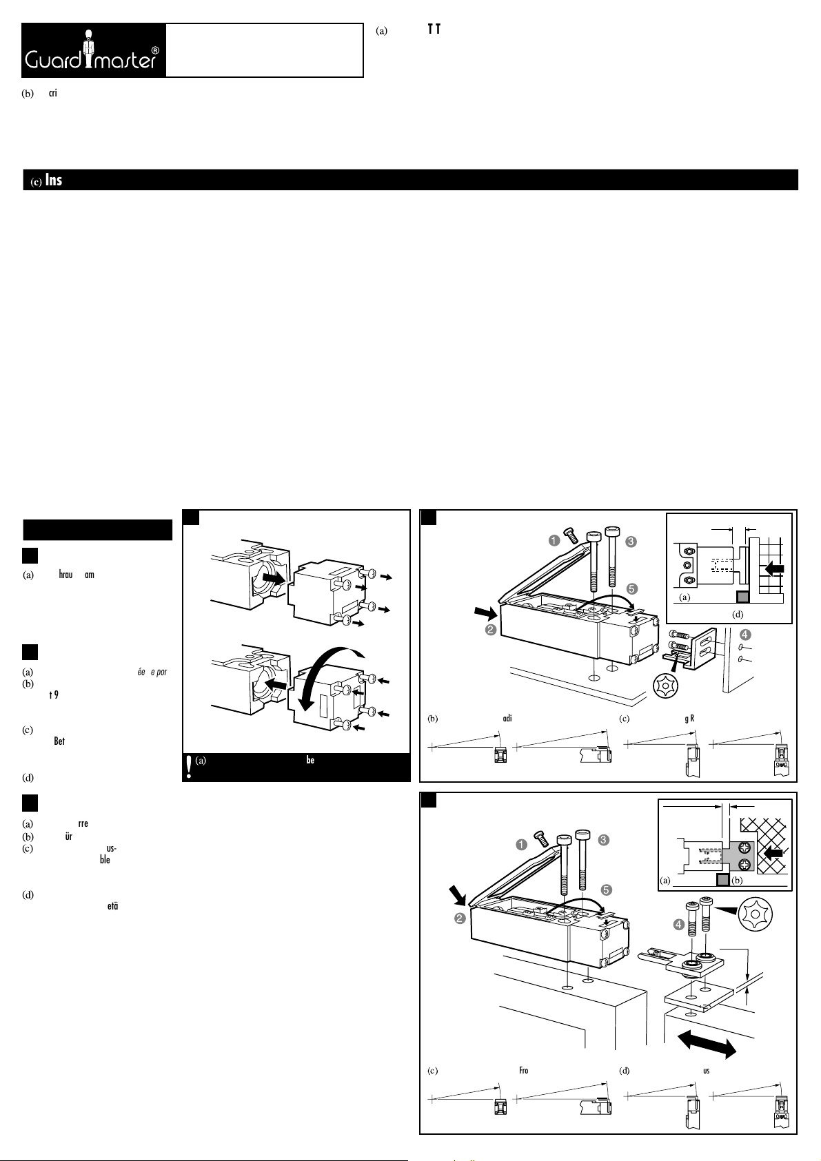
(a)
Die Schrauben am Schalterkopf müssen voll
angezogen sein, bevor der Schalter an den
Steuerkreis der Maschine angeschlossen
wird. /
Les vis de la tête du capteur doivent
être sérrées avant que le capteur soit
connecté au circuit de contrôle de la machine.
MIN.R 200mm
(c)
Minimum Operating Radius End-Entry using 90° actuator
(b)
Minimum Operating Radius Front-Entry using 90° actuator
MIN.R 150mm
MIN.R 150mm
MIN.R 150mm
MIN.R 200mm
(d)
Minimum Operating Radius End-Entry using flat actuator
(c)
Minimum Operating Radius Front-Entry using flat actuator
MIN.R 150mm
MIN.R 150mm
MIN.R 150mm
(a)
The switch head screws must be fully tightened before the
switch is connected to the machine control circuit.
M4
2 x M4
2.5mm
1
5
M4
3
4
(a)
Schutztür-Arretierungen
/
Butée de porte
(b)
Mindestbetriebsradius-Vordereingang
mit 90° Betätiger
/
Rayon minimal
d’ouverture - entrée avant - avec émetteur
90
°
(c)
Mindestbetriebsradius-Endeingang mit
90° Betätiger
/
Rayon minimal
d’ouverture - entrée arrière - avec émetteur
90
°
(d)
Schutztür
/
Porte de protection
2b
(a)
Schutztür-Arretierungen
/
Butée de porte
(b)
Schutztür
/
Porte de protection
(c)
Mindestbetriebsradius-Vordereingang
mit flachem/flexiblem Betätiger
/
Rayon minimal d’ouverture - entrée avant avec émetteur plat / flexible
(d)
Mindestbetriebsradius-Endeingang mit
flachem/flexiblem Betätiger
/
Rayon
minimal d’ouverture - entrée arrière - avec
émetteur plat / flexible
6mm min
7.5mm max
(a)
GUARD STOP
(d)
GUARD DOOR
1mm min
2.5mm max
(a)
GUARD STOP
(b)
GUARD DOOR
2
2
Page 2
5
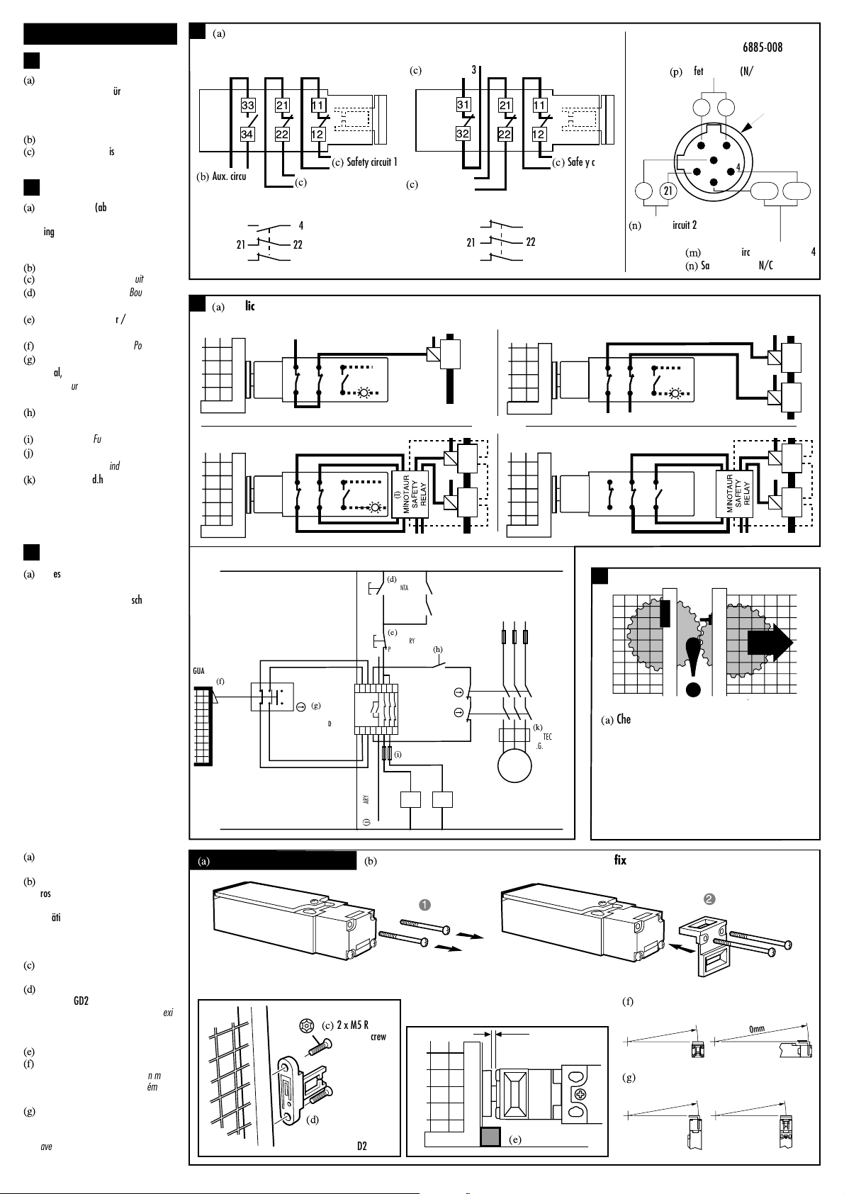
(a)
Check the machine is isolated and stopped
whenever the interlocked guard door is open.
IMPORTANT: After installation and commissioning,
the actuator, switch and switch lid fixing screws
should be coated with tamper evident varnish or
similar compound.
(a)
Application examples / Anwendungbeispiele / Exemples d'application
M
K1
K2
24VAC/DC, 110VAC, 230VAC
L1 L2 L3
(j)
AUXILIARY CIRCUIT
(ALARM OR INDICATION)
11
21
12
22
CADET 3
VERSION CCS2H
K1 (AUX)
K2 (AUX)
(d)
START
MOMENTARY
PUSH
BUTTON
(e)
STOP
MOMENTARY
PUSH
BUTTON
(i)
FUSES
(k)
CONTACT
PROTECTION
E.G. THERMAL
CUT OUT
A1 S13S23 33X1 41 13 23
A2 S14S24 34X2 42 14 24
(g)
MINOTAUR
MSR6R/T
SET TO D CHANNEL
SET TO R MODE
K1 K2
(h)
RESET
MOMENTARY
PUSH
BUTTON
GUARD
CLOSED
(f)
4
1
(a)
Optional GD2 accessory kit
2
(c)
2 x M5
Resistorx
security screws
2mm
(e)
GUARD STOP
Deutch /
Français
3
4
5
MIN.R 200mm
(g)
Minimum Operating Radius End-Entry using
flexible GD2 actuator
(f)
Minimum Operating Radius Front-Entry using
flexible GD2 actuator
MIN.R 60mm
MIN.R 150mm
MIN.R 60mm
(d)
IMPORTANT:Flexible actuator must
be used with GD2 end cap
(b)
GD2 kit comprises of stainless steel end cap, 2 x fixing screws and 1 flexible actuator
(a)
Anschlußdetails (abgebildet mit
geschlossener Schutztür und
eingesetztem Betätiger) /
CONNEXION –
Représentation détaillée (avec porte fermée
et émetteur inséré)
(b)
Hilfsstromkreis /
Circuit auxiliaire
(c)
Sicherheitsstromkreis /
Circuit de sécurité
(a)
Anschlußdetails (abgebildet mit
geschlossener Schutztür und
eingesetztem Betätiger) /
CONNEXION –
Représentation détaillée (avec porte fermée
et émetteur inséré)
(b)
Hilfsstromkreis /
Circuit auxiliaire
(c)
Sicherheitsstromkreis /
Circuit de sécurité
(d)
Start Druckknopftaster /
Bouton poussoir
de marche
(e)
Stop Druckknopftaster /
Bouton poussoir
d'arrêt
(f)
Schutzgitter geschlossen /
Porte fermée
(g)
Minotaur MSR6R/T eingestellt auf D
Kanal, eingestellt auf Betriebsart R
/
Minotaur MSR6R/T réglé sur le canal D
et réglé sur le mode R
(h)
Druckknopftaster für Neueinstellung /
Bouton poussoir de remise à zéro
(i)
Sicherungen /
Fusibles
(j)
Hilfskreis (Alarm oder Anzeige) /
Circuit
auxiliaire (alarme ou indication)
(k)
Kontaktschutz d.h. Wärmeausschaltung
/
Protection de contact e.g. coupe-circuit
thermique
(a)
Jedes Mal wenn die verriegelte
Schutzgittertür offen ist, prüfen, ob
Maschine isoliert und abgeschaltet ist.
WICHTIG: Nach Montage und
Inbetriebnahme sollten Betätiger,
Schalter u. Befestigungsschrauben für
Schalterdeckel zum Aufzeigen von
Eingriffen mit Lack oder ähnlichem
Material beschichtet werden /
Vérifiez que la machine soit arrêtée et
coupée lorsque la porte est ouverte.
IMPORTANT : Après l'installation et les
essais de mise en service, recouvrir de
vernis de blocage les vis de fixation de la
broche, de l’interrupteur et les vis du
couvercle
(a)
Optionaler GD2-Zubehörsatz /
Kit
d’accessoire GD2 en option
(b)
Der GD2-Satz enthält eine Endkappe aus
rostfreiem Stahl, 2
Befestigungsschrauben und 1 flexiblen
Betätiger. /
Le kit GD2 se compose d’un
chapeau d’extrémité en acier inoxydable,
de 2 vis de fixation et d’un émetteur
flexible.
(c)
Resistorx Sicherheitsschrauben /
Vis de
sécurité Resistorx
(d)
WICHTIG: Der flexible Betätiger muß
mit einer GD2-Endkappe verwendet
werden. /
IMPORTANT : l’émetteur flexible
doit être utilisé avec le chapeau d’extrémité
GD2
(e)
Schutztür-Arretierungen
/
Butée de porte
(f)
Mindestbetriebsradius-Vordereingang mit
flexiblem GD2-Betätiger
/
Rayon minimal
d’ouverture - entrée avant - avec émetteur
flexible GD2
(g)
Mindestbetriebsradius -
Endeingang mit
flexiblem GD2-Betätiger
/
Rayon
minimum de fonctionnement -
Entrée arrière-
avec émetteur flexible GD2
MINOTAUR
SAFETY
RELAY
2221
3433
1211
2221
3433
1211
2221
3433
1211
2221
3433
1211
(l)
MINOTAUR
SAFETY
RELAY
3
(a)
Connection details (shown with guard closed, actuator inserted)
22
21
34
33
31 32
33
34
12
11
22
21
2221
21
22
(b)
Aux. circuit
(c)
Safety circuit 2
(c)
Safety circuit 2
(c)
Safety circuit 3
(c)
Safety circuit 1
(c)
Safety circuit 1
1211
11
12
12
11
32
31
Brad Harrison connection
6 pole male, Type: BG 16885-008
(n)
Safety Circuit 2 (N/C)
(p)
Safety Circuit 1 (N/C)
1/2" UNF
15
6
2
22 21
4
3
12 11
(m)
Auxiliary Circuit (N/O) = 33/34
(n)
Safety Circuit 3 (N/C) = 31/32
31/3332/34
Page 3

Deutsch /
Français
(f)
90° ACTUATOR
2 SLOTS FOR
M4 SCREWS
8.75
18.25
23
1
3
29
8
3
7.5
24
12
(d)
FLAT ACTUATOR
3
15
25
12
2
4
0.8
13.5
1.7/1.9
3
25
R 0.5
R 0.25
MAX
R 0.5
(g)
METAL END CAP
12
55.5
15.5
15
8.5
40
(e)
FLEXIBLE ACTUATOR
INFORMATION IN REGARD TO UL508
Use copper conductors only.
Use polymeric conduit only.
End of line device.
Terminal tightening torque 9in/lbs.
When used in elevated ambients, temperature rating
shall not be less than ambient.
Electrical spec of rating code A600.
Max current: 120V AC - make 60A, break 6A.
240V AC - make 30A, break 3A.
Max. V/A: make 7200, break 720.
(a)
BETÄTIGER-RÜCKZUGABSTAND /
Distance
d’extraction de l’émetteur
(b)
Endeingang /
Entrée arrière
(c)
Vordereingang /
Entrée avant
(d)
Flacher Betätiger /
Emetteur plat
(e)
Flexibler Betätiger
/
Emetteur flexible
(f)
90°Betätigerführung
/
Guide d’émetteur
90
°
(g)
Metall-Endkappe
/
Chapeau d’extrémité,
métallique
(h)
GD2-Satz
/
Le kit GD2
Information bzgl. UL 508
Nur Kupferleiter benutzen
Nur Kunststoff-Kabelverschraubung benutzen
End-of-Line-Betriebsmittel 9in/lbs.
Bei Einsatz unter erhöhten Temperaturen darf die
Wenn in höheren Raumtemperaturen eingesetzt, darf der
Nennwert die Raumtemperatur nicht unterschreiten.
Umgebungstemperatur sein
Elektrisches Rating A600
Max. Strom: 120 VAC -Ein 60 A, Aus 6A
240 VAC -Ein 30 A, Aus 3A
Max. VA: Ein 7200, Aus 720
Informations en rapport avec la norme
UL508
Utiliser uniquement des conducteurs.
Utiliser des presses étoupe polymères.
Fin de ligne 9in/lbs
Pour utilisation en températures ambiantes élevées,
la classification température ne doit pas être
inférieure à la température ambiante.
Catégorie des pouvoir de coupure suivant A600.
Courant max: 120 VAC - Enclenchement 60A - Rupture 6A
140 VAC - Enclenchement 30A - Rupture 3A
Max V/A Enclenchement 7200 - Rupture 720
(h)
GD2 KIT
4.5
3.8 0
11/12
21/22
33/34
Contact Open
Contact Closed
11/12
21/22
31/32
Contact Open
Contact Closed
(a)
Actuator withdrawal distance
from full insertion: 2 N/C + 1 N/O (BBM)
Contact Open
Contact Closed
(a)
Actuator withdrawal distance
from full insertion: 2 N/C + 1 N/O (MBB)
(a)
Actuator withdrawal distance
from full insertion: 3 N/C
34.4
36.4
38.4
90.5
13.0
CTRS
20.0
CTRS
22.0
25.0
31.0
4.5
4.0
R2.15
13.0
31.0
M16 OR PG11
THREAD FORM
13.0
25.0
4.5
4.0
30.4
(c)
FRONT ENTRY
(b)
END ENTRY
3.8 0
3.3
3.8 0
11/12
21/22
33/34
Technical Specifications
Conforming to standard EN 1088, EN 60947-5-1,
EN 292, EN 60204-1
Safety contact 2N/C or 3N/C positive break
Designation/Utilisation cat.
A600/AC-15 (Ue) 600V 500V 240V 120V
(le) 1.2A 1.4A 3A 6A
N600/DC-13 (Ue) 600V 500V 250V 125V
(le) 0.4A 0.55A 1.1A 2.2A
Thermal current (lth) 10A
Min. current 5V 5mA DC
Typical contact resistance 5mΩ
Rtd. insulation voltage (Ui) 500V
Rtd. impulse withstand voltage (Uimp) 2500V
Auxiliary contacts 1N/O (with 2N/C safety only)
Pollution degree 3
Actuator travel for positive opening 5mm
Minimum operating radius 150mm (60mm with GD2 kit)
Break contact minimum force 15N
Max. actuation speed 160mm/s
Max. actuation frequency 2 cycle/second
Case material UL Approved glass filled polyester
Actuator material Stainless steel
Protection IP 67
Conduit entry M16 or Pg 11
Operating temperature -20 C to 80 C
Fixing 2 x M4
Mounting Any position
Mechanical life 1 x 10
6
Electrical life 1 x 10
6
Weight 80g
Colour Red
Cleaning May be high pressure steam cleaned
Torque settings Fixing bolts 2.5 to 3 Nm
Lid screws 0.4 to 0.45 Nm
Terminal screws 0.9 to 1.0 Nm
Head bolts 0.4 to 0.45 Nm
Note: The safety contacts of the Guardmaster switches are described as
normally closed (N/C) i.e. with the guard closed, actuator in place (where
relevant) and the machine able to be started.
Entspricht Normen: EN 1088, EN 60947-5-1,
EN 292, EN 60204-1
Sicherheitskontakt 2N/C oder 3N/C positive Unterbrechung
Verwendungskategorie
A600/AC-15 (Ue) 600V 500V 240V 120V
(le) 1.2A 1.4A 3A 6A
N600/DC-13 (Ue) 600V 500V 250V 125V
(le) 0.4A 0.55A 1.1A 2.2A
Thermischer Strom (lth) 10A
Mindeststrom 5V 5mA DC
Typischer Kontaktwiderstand 5mΩ
Nennisolationsspannung (Ui) 500N
Nennsteh-Stoßspannung (Uimp) 2500N
Hilfskontakte 1 N/0(Lieferbar mit 2 Sicherheits-
Öffnungskontakt)
Verunreinigungsgrad 3
Zwangsöffnungsweg d. Betätigers 5mm
Minimaler Betätigungsradius 150mm (60 mm mit GD2-Bausatz)
Min.kraft zur Kontaktunterbr. 15N
Max. Betätigergeschwindigkeit 160mm/s
Max. Betätigerfrequenz 2 Zyklen/Sek.
Gehäusematerial UL genehmigtes glas-gefülltes Polyester
Betätigermaterial Edelstahl
Schutzart IP 67
Rohrleitungseingang M16 oder Pg 11
Betriebstemperatur -20°C bis 80°C
Befestigung 2 x M4
Montage jede Stellung
Mech. Lebensdauer 1 x 10
6
Elektr. Lebensdauer 1 x 10
6
Gewicht 80g
Farbe rot
Reinigung mögl. Reinigung mit Hochdruckdampf
Drehmomenteinstellung:
Befestigungsbolzen 2.5 bis 3 Nm
Deckelschrauben 0.4 bis 0.45 Nm
Anschlußschrauben 0.9 bis 1.0 Nm
Kopfbolzen 0.4 bis 0.45 Nm
Hinweis: Die Sicherheitskontakte der Guardmaster Schalter werden als Öffner
beschrieben, d.h. das Schutzgitter ist geschlossen, der Betätiger angebracht (wo
erforderlich) und die Maschine kann gestartet werden.
Specifications techniques
Conforme aux normes EN 1088, EN 60947-5-1,
EN 292, EN 60204-1
Contact de sécurité 2N/C ou 3N/C rupture positive
Catégorie d'utilisation
A600/AC-15 (Ue) 600V 500V 240V 120V
(le) 1.2A 1.4A 3A 6A
N600/DC-13 (Ue) 600V 500V 250V 125V
(le) 0.4A 0.55A 1.1A 2.2A
Courant thermique (lth) 10A
Courant min. 5V 5mA DC
Résistance de contact 5mΩ
Tension d'isolement (Ui) 500V
Tension de tenue aux ondes de choc (Uimp) 2500V
Contacts auxiliaires 1N/0 (Pour la version 2 N/C de sécurité)
Degré de pollution 3
Parcours de l'actionneur pour
ouverture positive 5mm
Angle minimum d'entrée de broche 150mm (60mm avec kit GD2)
Force minimum rupture contact 15N
Vitesse max de la commande 160mm/s
Fréquence max de la commande 2 cycles/seconde
Boîtier polyester chargé verre approuvé UL
Matériel de l'actionneur acier inoxydable
Protection IP 67
Presse-étoupe M16 ou Pg 11
Température -20°C à 80°C
Fixation 2 x M4
Montage N'importe quelle position
Vie mécanique 1 x 10
6
Vie électrique 1 x 10
6
Poids 80g
Couleur Rouge
Nettoyage
Peut être nettoyé à la vapeur haute pression
Force de torsion:
Boulons de fixation 2.5 à 3 Nm
Vis du couvercle 0.4 à 0.45 Nm
Vis terminales 0.9 à 1.0 Nm
Boulons à tête 0.4 à 0.45 Nm
Note : Les contacts de sécurité des interrupteurs Guardmaster sont décrits
comme étant normalement fermés (N/C) i.e. avec la porte fermée,
l'actionneur en place (où il a lieu d'être) et la machine prête à fonctionner.
Technische Daten
(d)
Page 4

Security screwdriver
Replacement Resistorx security key
GD2 accessoy kit
Replacement actuators are available by arrangement.
Note: Access to spare actuators should be restricted to
authorised personnel to prevent bypassing of the safety function
TORX-Bit-Handhalter
TORX-Bit
GD2-Zubehörsatz
Ersatzbetätiger auf Anfrage
Anmerkung: Ersatzbetätiger dürfen nur autorisierten Personen
zugänglich sein, um ein Umgehen der Sicherheitsfunktion zu verhindern.
Tournevis de sécurité
Remplacement enbout tournevis
Kit d’accessoire GD2
Broche de remplacement Voir catalogue général
Note : L’accès à l’appareil doit être restreint au personnel autorisé pour
éviter toute fraude de la fonction de sécurité.
ZUBEHÖR
(e)
ACCESSORIES
ACCESSOIRES
WARTUNG
(f)
MAINTENANCE
MAINTENANCE
Every Week
Check alignment of actuator to switch and the correct operation of
the switching circuit. Also check for signs of abuse or tampering.
Inspect the switch casing & actuator for damage. Of particular
importance is damage which causes loss of sealing at the lid or
conduit entry, distortion of the actuator & damage to catch/entry
point and cam mechanism. Replace if apparent.
At least every 6 months
Isolate all power! Remove the lid. Inspect all terminals for tightness.
Clean out any accumulation of fine dirt etc. Check for any sign of wear
or damage, e.g. actuator wear, cam assembly wear, contact
oxidisation etc. and replace if apparent. Replace covers & fully tighten
the security screws. Reinstate the power & check for correct operation.
Re-apply tamper evident varnish or similar compound to fixings.
REPARATUR
(g)
REPAIR
RÉPARATION
If there is any malfunction or damage, no attempts at repair should
be made. The switch should be replaced before machine operation is
allowed.
DO NOT DISMANTLE THE UNIT.
Wöchentlich
Ausrichtung des Betätigers auf Schalter sowie korrekten Betrieb des
Schaltkreises überprüfen. Nach Zeichen für Mißbrauch oder unbefugte
Eingriffe suchen. Schaltergehäuse und Betätiger auf Beschädigungen
überprüfen. Besonders wichtig sind Überprüfungen auf Schäden, die
Dichtungsverluste am Deckel oder am Leitungsrohreingang,
Verformung des Betätigers & Beschädigung am Verschluß-
/Eingangspunkt und am Nockenmechanismus auslösen. Ggf.
ersetzen.
Mind. Alle 6 Monate
Strom abschalten! Die Abdeckung entfernen. Alle Anschlüsse auf
festen Sitz überprüfen. Jeglichen feinen Schmutz usw. entfernen. Auf
Verschleiß oder Schäden z.B. am Betätiger und der
Nockenanordnung sowie auf Kontaktoxidation usw. untersuchen und
ggf. ersetzen. Deckel wieder aufsetzen und Sicherheitsschrauben
anziehen. Maschine wieder anschalten & auf korrekten Betrieb
prüfen. Neubehandlung der Halterungen mit Lack oder ähnlichem
Material, um Eingriffe aufzuzeigen.
Falls Fehlfunktionen oder Schäden auftreten, keine Versuche zur
Reparatur unternehmen. Der Schalter sollte ersetzt werden, bevor die
Maschine gestartet wird.
GERÄT NIEMALS AUSEINANDERNEHMEN
Chaque semaine
Contrôler l'alignement de broche avec l'interrupteur, et le fonctionnement
correct du circuit de commutation. Vérifiez s'il y a des traces de
manipulation frauduleuse ou d'abus. Assurez-vous que ni le boîtier de
l'interrupteur ni l'actionneur ne soient endommagés. De nombreuses
pannes sont provoquées par la perte de l’étanchéité du couvercle et du
presse-étoupe, par la déformation de la broche, par la dégradation du kit
de maintien ou du point d’entrée de la broche, par la dégradation du
mécanisme à came. Dans ce cas, remplacez l'appareil.
Tous les 6 mois au moins
Coupez l'alimentation de la machine.
Enlever le couvercle
. Vérifiez les
connexions aux bornes. Enlevez toute poussière accumulée, etc. Vérifiez
s'il y a des traces d'usure ou de dommages, e.g. usure de la broche, du
mécanisme à came, oxydation des contacts, etc. Dans ce cas, remplacez
le dispositif. Remettez les couvercles en place et serrez à fond les vis de
sécurité. Enclenchez l'alimentation et contrôlez le bon fonctionnement de
l'ensemble. Appliquez une couche de vernis ou autre produit semblable
aux fixations.
Il doit être remplacé immédiatement avant la remise en production
de la machine. L'interrupteur doit être remplacé avant de remettre la
machine en service.
DANS TOUS LES CAS, NE DISLOQUEZ PAS L’APPAREIL.
Drg No: 44545 / Issue No:1
R
 Loading...