

Page 1
(f) MAINTENANCE
Every Week
Check the correct operation of the switching circuit. Also check for
signs of abuse or tampering. Inspect the switch casing & shaft for
damage. Of particular importance is damage which causes loss of
sealing at the lid or conduit entry.
At least every 6 months
Isolate all power! Remove the lid. Inspect all terminals for tightness.
Clean out any accumulation of fine dirt etc. Check for any sign of wear
or damage, e.g. cam assembly wear, contact oxidisation etc. and
replace if apparent. Replace covers & fully tighten lid screws.
Reinstate the power & check for correct operation. Re-apply tamper
evident varnish compound to fixings.
(g) REPAIR
If there is any malfunction or damage, no attempts at repair should
be made. The switch should be replaced before machine operation is
allowed. If appropriate return the switch to supplier.
DO NOT DISMANTLE THE UNIT.
WARTUNG
ZUBEHÖR
Wöchentlich
Die korrekte Funktion des Schaltkreises prüfen. Auch wegen
Misshandlung bzw. Manipulation prüfen. Nachsehen, ob das
Schaltergehäuse & die Welle beschädigt sind. Besonders auf
beschädigte Deckel oder Kabeleinläufe aufpassen, weil sie vielleicht
nicht ordentlich abdichten.
Mind. Alle 6 Monate
Den Strom ausschalten! Den Deckel abnehmen. Nachsehen, dass alle
Klemmen festsitzen. Feinen Staub usw. abwischen. Wegen
Abnutzung oder Beschädigung prüfen, z.B. abgenutzte Mitnehmer,
oxidierte Kontakte usw., wenn defekt auswechseln. Deckel wieder
aufsetzen und mit den Schrauben festschrauben. Den Strom
anschalten und die korrekte Funktion prüfen. Mit Lack zum Schutz
vor Manipulation anstreichen.
REPARATUR
Falls Fehlfunktionen oder Schäden auftreten, keine Versuche zur
Reparatur unternehmen. Der Schalter muß ersetzt werden, bevor die
Maschine wieder gestartet wird. Den Schalter ggf. an den Lieferanten
zurückschicken.
GERÄT NIEMALS AUSEINANDERNEHMEN
MAINTENANCE
Chaque semaine
Vérifier le fonctionnement du circuit de commutation. Chercher
également les éventuels signes de tentative d'effraction ou de
tripatouillage. Vérifier l'état du boîtier et de l'axe de l'interrupteur en
accordant une attention toute particulière aux dégâts qui pourraient
provoquer un défaut d'étanchéité au niveau du couvercle ou de l'entrée
du conduit.
Tous les 6 mois au moins
Couper et isoler l'alimentation électrique. Démonter le couvercle. Vérifier
le serrage de toutes les bornes. Eliminer toutes les traces de
poussière/crasse, etc. Vérifier l'état et l'usure de la came, oxydation des
contacts, etc.). Remplacer si nécessaire. Remettre le couvercle en place
en serrant les vis à fond. Remettre sous tension et vérifier le
fonctionnement. Mettre une goutte de vernis témoin sur la tête des vis.
RÉPARATION
En cas de dysfonctionnement ou de dégradation, ne pas attendre
pour réparer. L'interrupteur doit être remplacé immédiatement avant
le démarrage de la machine. Si c'est nécessaire, veuillez rendre
l'interrupteur au fournisseur.
DANS TOUS LES CAS, NE DISLOQUEZ PAS L'APPAREIL.
SPRITE 3
(b) Description
The Sprite 3 is a hinge operated interlock switch. It interlocks the guard to the
machine control system and ensures machine power is isolated and remains
isolated whilst the guard is open.
(c) Installation Instructions
RETAIN THESE INSTRUCTIONS
Installation must be in accordance with the following steps and must be
carried out by suitably competent personnel.
This device is intended to be part of the safety related control system of a
machine. Before installation, a risk assessment should be performed to
determine whether the specifications of this device are suitable for all
foreseeable operational and environmental characteristics of the machine to
which it is to be fitted.
At regular intervals during the life of the machine check whether these
characteristics foreseen remain valid and inspect this device for evidence of
accelerated wear, material degradation or tampering. If necessary the device
should be replaced . Guardmaster cannot accept responsibility for a failure of
this device if the procedures given in this sheet are not implemented or if it
is used outside the recommended specifications in this sheet.
Guard stops and guides must be fitted.
Exposure to shock and/or vibration in excess of those stated in
IEC 68 part: 2-6/7 should be prevented.
Adherence to the recommended maintenance instructions forms part of the
warranty.
Beschreibung
Der Sprite 3 ist ein Sicherheitsverriegelungsschalter mit Scharnierbetätigung. Er
verriegelt die Schutztür zum Maschinensteuersystem. Er garantiert, dass der
Maschinenstrom ausgeschaltet ist und ausgeschaltet bleibt, so lange die Schutztür
offen ist.
DIESE ANLEITUNG AUFBEWAHREN
Der Einbau muß durch einen entsprechend qualifizierten Mitarbeiter
erfolgen, und folgende Schritte müssen hierbei beachtet werden.
Dieses Gerät ist für den Einsatz als Teil des sicherheitsbezogenen
Steuerungssystems einer Maschine gedacht. Vor dem Einbau sollte eine
Risikoanalyse durchgeführt werden, um festzustellen, ob sich dieses
Geräts technisch für alle voraussehbaren Betriebs- und
Umweltsbedingungen der Maschine, für die es bestimmt ist, eignet.
Prüfen Sie in regelmäßigen Abständen während der Lebensdauer der
Maschine, ob diese voraussehbaren Bedingungen auch weiterhin gelten,
und überprüfen sie dieses Gerät auf vorschnellen Verschleiß,
Qualitätsverlust des Materials oder unbefugte Eingriffe. Ggf. sollte das Gerät
ausgewechselt werden. Guardmaster kann keine Haftung für ein Versagen
dieses Geräts übernehmen, wenn die auf diesen Seiten aufgeführten
Verfahren nicht angewandt werden oder wenn das Gerät nicht laut der
empfohlenen Spezifikationen verwendet wird. Schutzgittersperren und leitvorrichtungen müssen angebracht werden.
Das Gerät sollte keinen Stößen und/oder Erschütterungen ausgesetzt
werden, die stärker sind als die in IEC68 Teil: 2-6/7 beschriebenen.
(a) Miniature Hinge Operated Interlock Switch
Miniatur-Scharnier-Sicherheitsschalter
Capteur a Charniere Miniature
Einbauanleitung
Die Einhaltung der empfohlenen Wartungsanweisungen ist Teil der Garantie.
Description
Sprite 3 est un interrupteur de sécurité actionné par charnière qui agit sur le circuit de
commande de la machine et garantit le maintien de l'isolement de l'alimentation tant
que la protection est ouverte.
Notice d'installation
INSTRUCTIONS A RETENIR
L'installation doit être menée conformément aux étapes suivantes et doit
être effectuée par un personnel expérimenté.
Cet appareil est destiné à faire partie du système de contrôle de sécurité
d'une machine. Avant l'installation, on doit procéder à une estimation de
risque afin de déterminer si les spécifications de l'appareil conviennent à
toutes les caractéristiques prévisibles de fonctionnement et d'environnement
de la machine à laquelle il doit être fixé.
A intervalles réguliers durant la vie de la machine, vérifiez si les
caractéristiques prévues sont toujours valables et inspectez de l'appareil afin
de détecter toute détérioration accélérée, toute dégradation du matériel ou
manipulation frauduleuse. Si nécessaire, remplacez l'appareil. Guardmaster
n'est pas responsable d'un défaut de l'appareil si la procédure décrite dans
cette notice n'a pas été appliquée ou si le l'appareil est utilisé sans tenir
compte des recommandations.
Les butées de porte et les dispositifs de guidage doivent être fixés.
Evitez l'exposition aux chocs et/ou aux vibrations dépassant les limites
données dans la norme CEI 68 paragraphe 2-6/8.
Suivre rigoureusement les instructions de maintenance pour valider la
garantie constructeur.
Declaration of Conformity / Konformitätserklärung / Déclaration de conformité
This is to declare that the Guardmaster Sprite 3 conforms with the Essential Health & Safety Requirements (EHSR's) of the European Machinery Directive
(98/37/EC) and the relevant requirements of the Low Voltage Directive (73/23/EEC as amended by 93/68 EEC). The Sprite 3 also conforms to EN 1088, EN
60947-5-1, EN 292, EN 60204-1 and are Third Party Approved by TUV and UL.
Signed for EJA Limited (Guardmaster)
S. F. Mitchell
Deputy Managing Director
ISO 9001
FM 21701
EJA Ltd. (Guardmaster)
Hindley Green Ind. Est. Wigan, England WN2 4HR
Tel: 01942 255166 (Int: +441942 255166)
Fax: 01942 523259 (Int: +44 1942 523259)
Web site: www.guardmaster.co.uk
Guardmaster Sicherheitstechnik GMBH.
Am Stadion 15, 42897 Remscheid, Germany
Telefon: (02191) 96850 Telefax: (02191) 968520
Guardmaster Sarl
EUROCAP/COURTIMMO, 62231 COQUELLES, France
Téléphone : 03 21 00 73 74 - Télécopie : 03 21 00 12 34
Site internet France : http://www.guardmaster.fr
E-mail : directinfo@guardmaster.fr
Drg No: 34555 / Issue No: 1
Deutch /
Français
1
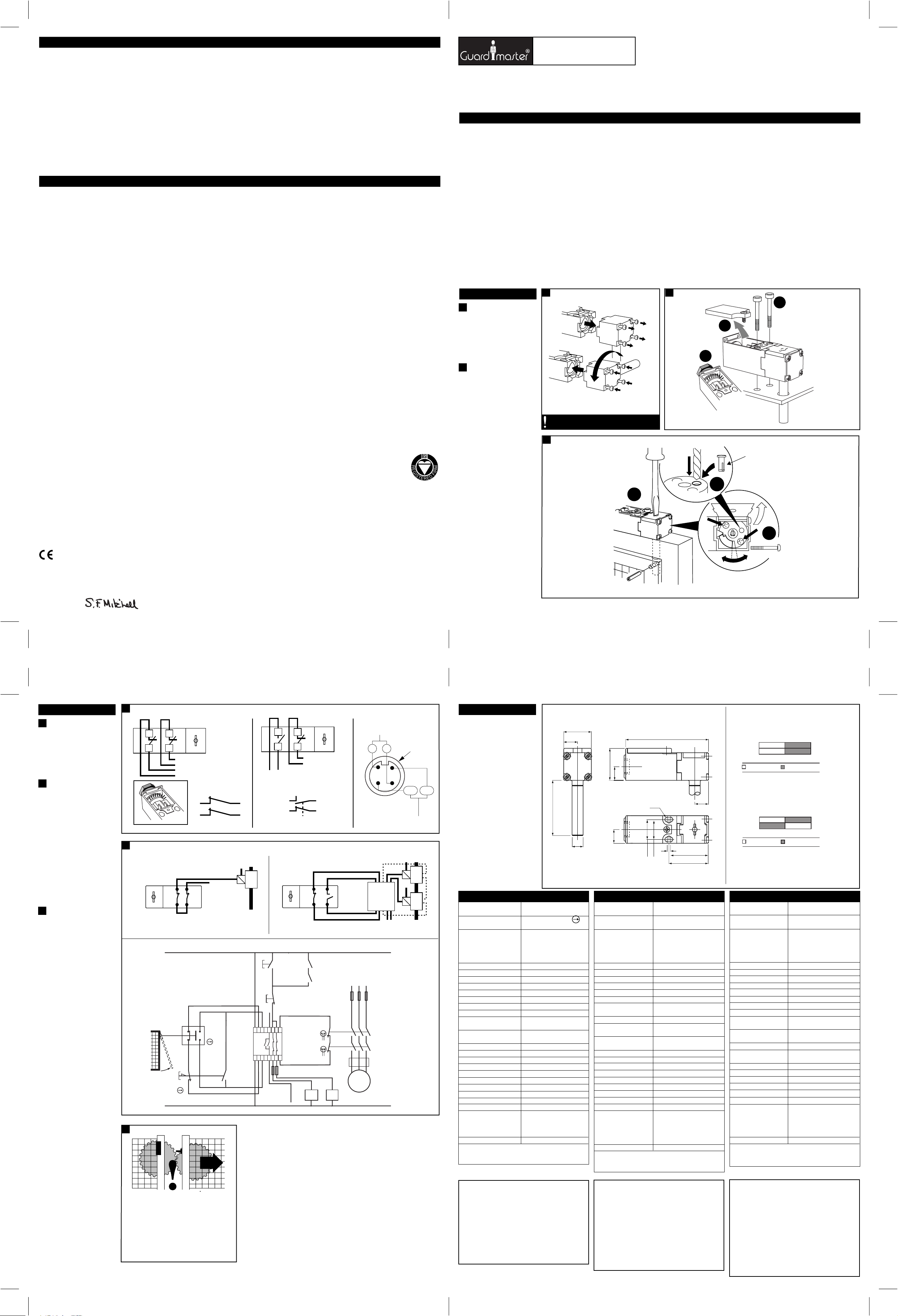
(a)
Die Schrauben am Schalterkopf müssen voll
angezogen sein, bevor der Schalter an den
Steuerkreis der Maschine angeschlossen
wird. /
Les vis de la tête du capteur doivent
être sérrées avant que le capteur soit
connecté au circuit de contrôle de la machine.
(b)
Drehmomenteinstellung
/
Force de torsion
3
(a)
12 mm Bohrtiefe
perçage 12 mm
(b)
Verstellung
/
Réglage
/
Profondeur de
1
(b) TORQUE - 0.4 Nm
(a)
The switch head screws must be fully tightened before the
switch is connected to the machine control circuit.
3
1
2
Ø 3mm
3
2 x M4 - 1 Nm
1
2
(a) Depth of drilling 12mm
3
2
(b) ADJUSTMENT
Deutch /
Français
4
(a) Anschlußdetails (abgebildet mit
geschlossener Schutztür und
eingesetztem Betätiger) /
Représentation détaillée (avec porte fermée
et émetteur inséré)
(b) Hilfsstromkreis /
(c) Sicherheitsstromkreis /
CONNEXION –
Circuit auxiliaire
Circuit de sécurité
5
(a) Anschlußdetails (abgebildet mit
geschlossener Schutztür und
eingesetztem Betätiger) /
Représentation détaillée (avec porte fermée
et émetteur inséré)
(b) Hilfsstromkreis /
(c) Sicherheitsstromkreis /
(d) Start Druckknopftaster /
de marche
(e) Stop Druckknopftaster /
(f) Sicherungen /
(g) Hilfskreis (Alarm oder Anzeige) /
(h) Kontaktschutz d.h. Wärmeausschaltung
d'arrêt
auxiliaire (alarme ou indication)
/
Protection de contact e.g. coupe-circuit
thermique
Circuit auxiliaire
Fusibles
CONNEXION –
Circuit de sécurité
Bouton poussoir
Bouton poussoir
Circuit
6
(a) Jedes Mal wenn die verriegelte
Schutzgittertür offen ist, prüfen, ob
Maschine isoliert und abgeschaltet ist.
WICHTIG: Nach Montage und
Inbetriebnahme sollten Betätiger,
Schalter u. Befestigungsschrauben für
Schalterdeckel zum Aufzeigen von
Eingriffen mit Lack oder ähnlichem
Material beschichtet werden /
Vérifiez que la machine soit arrêtée et
coupée lorsque la porte est ouverte.
IMPORTANT : Après l'installation et les
essais de mise en service, recouvrir de
vernis de blocage les vis de fixation de la
broche, de l’interrupteur et les vis du
couvercle
4
(a) Connection details (shown with guard closed, actuator inserted)
11
21
12
22
(c) Safety circuit
2 N/C
2122
1112
1 x M16/1 x Pg 9
5
(a) Application examples / Anwendungbeispiele / Exemples d'application
1211
2221
24VAC/DC, 110VAC, 230VAC
23
11
MINOTAUR
MSR9T
E-STOP
LATCHING
E-STOP
BUTTON
24
12
23
24
(b) Auxiliary circuit
(d) START
MOMENTARY
PUSH
BUTTON
A1 S13 S21 31 13 23
A2 S14 S22
6
11
12
(c) Safety circuit 1
1 N/C + 1 N/O
24 23
12
(e) STOP
MOMENTARY
PUSH
BUTTON
X1
X232 14 24
(f) FUSES
K1 K2
(g) AUXILIARY
CIRCUIT (ALARM
OR INDICATION)
1211
K1 (AUX)
K2 (AUX)
11
Brad Harrison connection
4 pole male, Type: BG 16882-008
(c) Safety Circuit 1 (N/C)
12 11
2
3
(b) Auxiliary Circuit (N/O) = 23/24
(c) Safety Circuit 2 (N/C) = 21/22
M12
1
4
21/2322/24
Deutsch /
(a) BETÄTIGER-RÜCKZUGABSTAND /
Distance d’extraction de l’émetteur
Français
55
12.5
25
Ø 10
29
12.5
12.5
R 2.1
18.0
16.5
(a)
Actuator withdrawal distance
from full insertion: 2 N/C
75
3° 0°
11/12
21/22
12.5
Contact Open
(a)
Actuator withdrawal distance
from full insertion: 1 N/C + 1 N/O
Contact Closed
3° 0°
11/12
23/24
3
34.5
Contact Open
Contact Closed
36
2423
unit
Relay
N/O, N/C
monitoring
MINOTAUR
L1 L2 L3
K1
K2
(h) CONTACT
PROTECTION
E.G. THERMAL
CUT OUT
M
(d)
Technical Specifications
Conforming to standards EN 1088, EN 60947-5-1, EN 292,
Safety contacts 2 N/C direct opening
1 N/C, 1 N/O direct opening
Designation/Utilisation cat.
B600/AC-15 (Ue) 600V 500V 240V 120V
(le) 0.6A 0.72A 1.5A 3A
P600/DC-13 (Ue) 600V 500V 250V 125V
(le) 0.2A 0.27A 0.55A 1.1A
Thermal current (lth) 5A
Min. current 5V 5mA DC
Typical contact resistance 5mΩ
Safety contact gap >2mm
Rtd. insulation voltage (Ui) 500V
Rtd. impulse withstand voltage (Uimp) 2500V
Auxiliary contacts 1N/O (available with 1N/C safety contacts)
Pollution degree 3
Shaft rotation to achieve contact Adjustable
operation 2 N/C 11° (max) 3° (min)
1 N/C, 1 N/O 11° (max) 3° (min)
Break contact minimum force 20 cNm
Case material UL Approved glass filled polyester
Actuator material Stainless steel
Protection IP 67
Conduit entry M16 or Pg 9
Operating temperature -20° C to 80° C
Fixing 2 x M4
Cleaning May be steam cleaned
Mechanical life 1,000,000
Colour Red
Torque settings Fixing bolts 2.5 to 3 Nm
Lid screws 0.4 to 0.45 Nm
Terminal screws 0.9 to 1.0 Nm
Head screws 0.4 to 0.45 Nm
Note: The safety contacts of the Guardmaster switches are described as
normally closed (N/C) i.e. with the guard closed, actuator in place (where
relevant) and the machine able to be started.
EN 60204-1
Adjustable
Technische Daten
Entspricht Normen: EN 1088, EN 60947-5-1, EN 292,
Sicherheitskontakt 2 N/C direkt öffnender
1 N/C or 1 N/O direkt öffnender
Verwendungskategorie
B600/AC-15 (Ue) 600V 500V 240V 120V
(le) 0.6A 0.72A 1.5A 3A
P600/DC-13 (Ue) 600V 500V 250V 125V
(le) 0.2A 0.27A 0.55A 1.1A
Thermischer Strom (lth) 5A
Mindeststrom 5V 5mA DC
Typischer Kontaktwiderstand 5mΩ
Sicherheitskontaktlücke >2mm
Nennisolationsspannung (Ui) 500N
Nennsteh-Stoßspannung (Uimp) 2500N
Hilfskontakte 1 N/0 (Lieferbar mit 1 Sicherheits-
Verunreinigungsgrad 3
Wellendrehung für Kontakt Verstellbar
2 N/C 11° (max) 3° (min)
1 N/C, 1 N/O 11° (max) 3° (min)
Min.kraft zur Kontaktunterbr. 20 cNm
Gehäusematerial UL genehmigtes glas-gefülltes Polyester
Schutzart IP 67
Rohrleitungseingang 1 x M16 or 1x Pg 9
Betriebstemperatur -20°C bis 80°C
Befestigung 2 x M4
Reinigung mögl. Reinigung mit Hochdruckdampf
Mech. Lebensdauer 1,000,000
Farbe rot
Drehmomenteinstellung:
Befestigungsbolzen 2.5 bis 3 Nm
Deckelschrauben 0.4 bis 0.45 Nm
Anschlußschrauben 0.9 bis 1.0 Nm
Die Schrauben am Schalterkopf
Hinweis: Die Sicherheitskontakte der Guardmaster Schalter werden als Öffner
beschrieben, d.h. das Schutzgitter ist geschlossen, der Betätiger angebracht (wo
erforderlich) und die Maschine kann gestartet werden.
EN 60204-1
Öffnungskontakt)
Verstellbar
0.4 bis 0.45 Nm
Specifications techniques
Conforme aux normes EN 1088, EN 60947-5-1, EN 292,
Contact de sécurité 2 N/C ouverture directe
1 N/C ou 1 N/C ouverture directe
Catégorie d'utilisation
B600/AC-15 (Ue) 600V 500V 240V 120V
(le) 0.6A 0.72A 1.5A 3A
P600/DC-13 (Ue) 600V 500V 250V 125V
(le) 0.2A 0.27A 0.55A 1.1A
Courant thermique (lth) 5A
Courant min. 5V 5mA DC
Résistance de contact 5mΩ
Espace contact de sécurité >2mm
Tension d'isolement (Ui) 500V
Tension de tenue aux ondes de choc (Uimp) 2500V
Contacts auxiliaires 1N/0 (Pour la version 1 N/C de sécurité)
Degré de pollution 3
Rotation de l'axe pour obtenir le Réglable
fonctionnement du contact 2 N/C 11° (maxi) 3° (mini)
1 N/C, 1 N/O 11° (maxi) 3° (mini)
Force minimum rupture contact 20 cNm
Boîtier polyester chargé verre approuvé UL
Protection IP 67
Presse-étoupe 1 x M16 ou 1 x Pg 9
Température -20°C à 80°C
Fixation 2 x M4
Nettoyage
Vie mécanique 1,000,000
Couleur Rouge
Force de torsion:
Boulons de fixation 2.5 à 3 Nm
Vis du couvercle 0.4 à 0.45 Nm
Vis terminales 0.9 à 1.0 Nm
Les vis de la tête 0.4 à 0.45 Nm
Note : Les contacts de sécurité des interrupteurs Guardmaster sont décrits
comme étant normalement fermés (N/C) i.e. avec la porte fermée,
l'actionneur en place (où il a lieu d'être) et la machine prête à fonctionner.
EN 60204-1
Réglable
Peut être nettoyé à la vapeur
(a) Check the machine is isolated and stopped
whenever the interlocked guard door is open.
IMPORTANT: After installation and commissioning,
the actuator, switch and switch lid fixing screws
should be coated with tamper evident varnish or
similar compound.
INFORMATION IN REGARD TO UL508
Use copper conductors only.
Use Polymeric conduit only.
Use one conduit entrance for field connections.
When used in elevated ambients, temperature rating of
field wiring shall not be less than ambient.
Terminal tightening torque: 9 in/lb.
Contact block tightening torque: 9 in/lb.
Electrical spec of rating code B600.
Max current: 120V AC - make 30A, break 3A.
240V AC - make 15A, break 1.5A.
Max. V/A: make 3600, break 360.
Information bzgl. UL 508
Nur Kupferleiter verwenden.
Nur Kunststoffkabelkanal verwenden.
Einen Kabeleinlauf für Anschlüsse im Freien verwenden.
Bei Einsatz in höheren Umgebungstemperaturen darf der
Temperaturnennwert der Verdrahtung die
Umgebungstemperatur vor Ort nicht unterschreiten.
Klemmenspanndrehmoment: 50 cm/kg.
Kontaktblock-Spanndrehmoment: 50 cm/kg.
Elektrisches Rating B600
Max. Strom: 120 VAC -Ein 30 A, Aus 3A
240 VAC -Ein 15 A, Aus 1.5A
Max. VA: Ein 3600, Aus 360
Informations en rapport avec la norme
UL508
Utiliser uniquement des conducteurs en cuivre.
Utiliser uniquement des conduits en polymère.
Utiliser une seule entrée de conduit pour les connexions.
Pour une utilisation dans des températures ambiantes
élevées, prévoir des câbles électriques d'une classe leur
permettant de supporter ces températures.
Couple de serrage des bornes : 9 pouces/livre.
Couple de serrage des contacts : 9 pouces/livre.ivant
B600.
Courant max: 120 VAC - Enclenchement 30A - Rupture 3A
140 VAC - Enclenchement 15A - Rupture 1.5A
Max V/A Enclenchement 3600 - Rupture 360
 Loading...