

Page 1
TLSZR/L-GD2 Guard Locking Switch Installation Instructions
IMPORTANT
IMPORTANT
WICHTIG
IMPORTANTE
IMPORTANTE
IMPORTANTE
Do not attempt to install this device unless the installation instructions
have been studied and understood. This installation instruction sheet is
available in some languages at www.rockwellautomation.com/literature.
Select publication language and type “TLSZR/L-GD2” in the search field.
Ne pas tenter pas d'installer ce dispositif sans avoir étudié et compris les
instructions d'installation. Cette notice d'installation est disponible dans
certaines langues sur le site www.rockwellautomation.com/literature.
Sélectionner la langue de la publication et saisir « TLSZR/L-GD2 » dans le
champ de recherche.
Versuchen Sie nicht, dieses Gerät zu installieren, bevor Sie die
Installationsanleitung gelesen und verstanden haben. Diese
Installationsanleitung steht in mehreren Sprachen unter der folgenden
Adresse zur Verfügung:www.rockwellautomation.com/literature. Wählen
Sie unter "Publication Language" die entsprechende Sprache aus und
geben Sie "TLSZR/L-GD2" in das Suchfeld ein.
Non installare questo dispositivo senza prima avere letto e compreso le
istruzioni per l'installazione. Queste istruzioni per l'installazione sono
disponibili per alcune lingue sul sito www.rockwellautomation.com/literature.
Selezionare la lingua della pubblicazione e digitare "TLSZR/L-GD2" nel campo
di ricerca.
Não instale esse dispositivo sem estudar e compreender as instruções de
instalação. Essa folha de instruções de instalação está disponível em
algumas línguas em www.rockwellautomation.com/literature. Selecione
a língua de publicação e escreva "TLSZR/L-GD2" no campo de pesquisa.
No instale este dispositivo sin estudiar y entender las instrucciones de
instalación. Esta hoja de instrucciones de instalación está disponible en
algunos idiomas en www.rockwellautomation.com/literature. Seleccione
el idioma de publicación e ingrese "TLSZR/L-GD2" en el campo de
búsqueda.
Page 2

TLSZR/L-GD2
Table of Contents
Installation Instructions .....................................................................................................................................3
Technical Specifications.....................................................................................................................................4
Dimensions [mm (in.)] ........................................................................................................................................6
Mounting Information [mm (in.)] ...................................................................................................................7
Allowable Approach Directions ..............................................................................................................8
Clearance in Closed Position [mm (in)].................................................................................................8
Auxiliary/Manual Release [mm (in.)]......................................................................................................8
Minimum Operating Radius [mm (in.)].................................................................................................9
Manual Override Key for Power-to-Release Version........................................................................ 9
Connections ........................................................................................................................................................ 10
Status/Diagnostic LED Indicator.................................................................................................................. 10
Commissioning.................................................................................................................................................. 11
“Multi-Time” Learn Process.................................................................................................................... 11
“One-Time” Learn Process...................................................................................................................... 12
Wiring Diagrams................................................................................................................................................ 13
Troubleshooting Series Circuit ............................................................................................................. 13
Unit Response Time.................................................................................................................................. 14
Application Wiring Example.................................................................................................................. 15
Recommended Relays..................................................................................................................................... 16
Maintenance ....................................................................................................................................................... 16
Monthly......................................................................................................................................................... 16
Repair............................................................................................................................................................. 16
Declaration of Conformity ............................................................................................................................. 16
2 10000302608 Ver 00 July 2012
Page 3
TLSZR/L-GD2
IMPORTANT: SAVE THESE INSTRUCTIONS FOR FUTURE USE
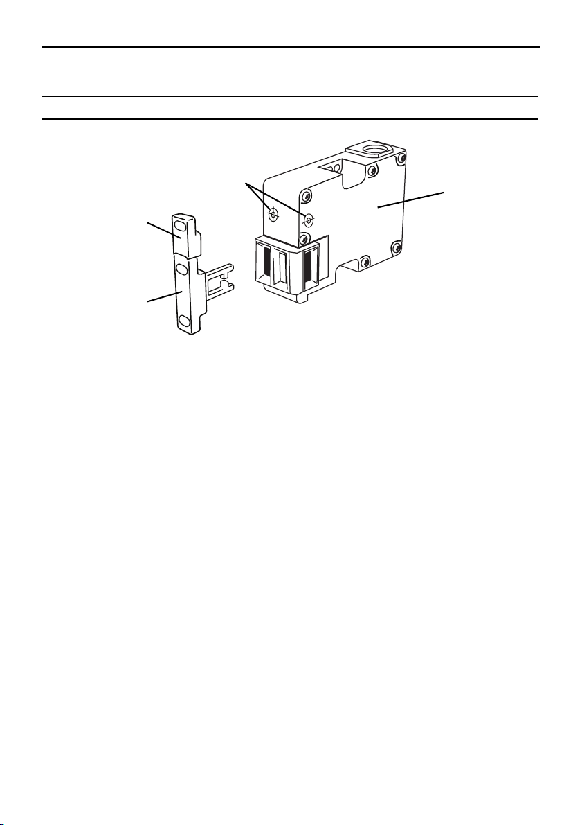
Target
Actuator
TLSZR/L-GD2
Switch
Target
Alignment
Marks
Installation Instructions
Installation must be in accordance with the following steps and stated specifications and should
be carried out by competent personnel. The unit is not to be used as a mechanical stop. Guard
stops and guides must be fitted. Adherence to the recommended maintenance instructions forms
part of the warranty.
This device is intended to be part of the safety related control system of a machine. Before
installation, a risk assessment should be performed to determine whether the specifications of
this device are suitable for all foreseeable operational and environmental characteristics of the
machine to which it is to be fitted. Refer to Technical Specifications for certification information
and ratings.
Use nonremovable screws, bolts, or nuts to mount the switch and actuators. Do not over torque
the mounting hardware.
For use with flexible actuator only, 440G-A27143.
10000302608 Ver 00 July 2012 3
Page 4

TLSZR/L-GD2
Technical Specifications
Safety Ratings
Standards IEC 60947-5-3, IEC 60947-5-1, IEC 61508, EN ISO 13849-1, IEC 62061, ISO 14119
Safety Classification: Guard door sensing PLe per ISO 13849-1, SIL 3 per IEC 61508 and IEC 62061, PDF-M per IEC 60947-5-3
Functional Safety Data: Guard door sensing PFHD: 1.69 x 10
Certifications CE Marked for all applicable EU directives, cULus (UL 508), and TÜV.
Dual channel interlock may be suitable for use in application up to PLe (according
to ISO 13849-1) and for use up to SIL3 systems (according to IEC 62061)
depending application characteristics. Mission ti me/PTI: 20 years or 1 x 10
Operating Characteristics
TLSZR-GD2 Power to release
TLSZL-GD2 Power to lock
Assured Locking Distance [mm (in.)] Maximum target distance: 13 (0.51)
Torque for M5 Mounting 1.4 Nm (12.39 lb-in.)
Torque for Cover Mounting 1.2 Nm (10.62 lb-in.)
Locking Force Fmax Plastic pins: 1950 N (488 lb) Steel bolts: 2600 N (585 lb)
Locking Force Fzh (with EN/ISO 14119) Plastic pins: 1500 N (337 lb) Steel bolts: 2000 N (450 lb)
Maximum Output Current (all outputs) 200 mA
Current Consumption - solenoid not energized (no load
supply current)
Current Consumption - solenoid energized (no load supply
current)
Solenoid Duty Cycle 100%
Off-State Current < 0.5 mA DC
Maximum Number of Switches, connected in series Unlimited. See “Unit Response Time” on page 14.
Operating Voltage Ue 24V DC +10% / -15%
Frequency of Operating Cycle 1 Hz
Actuation Speed, Max. 160 mm (6.29 in.) per second
Actuation Speed, Min. 100 mm (3.94 in.) per minute
Response Time (Off) 75 ms first switch, 25 ms additional for each switch
Utilization Category (IEC 60947-5-2) DC-13 24V 200 mA
Impulse Withstand Voltage Uimp 250V
Poll ution Degre e 3
Protection Class 2
Mechanical Life 1 x 10
Maximum clearance between actuator base and switch in the door-closed
position: 5 mm (See “Clearance in Closed Position [mm (in)]” on page 8)
50 mA
120 mA (260 mA inrush)
6
cycles
-9
6
cycles.
Outputs (Guard door closed and locked)
Outputs Description Status
Safety 2 x PNP, 0.2 A max. ON (+24V DC)
Auxiliary 1 x PNP, 0.2 A max. OFF (0V DC)
Environmental
Operating Temperature [C (F)] -10°…+60° C (+14°…+140° F)
Operating Humidity 5%…95% relative
4 10000302608 Ver 00 July 2012
Page 5

Environmental
Enclosure Ingress Rating NEMA 3, 4X, 12, 13, IP66, IP67, IP69K
Shock and Vibration IEC 68-2-27 30 g, 11 ms/IEC 68-2-6 10…55Hz
Radio Frequency IEC 610 00-4-3
IEC 61000-4-6
General
Housing Material UL approved glass filled PBT
Actuator Material Stainless Steel
Target Material UL approved glass filled PBT
Connection M12 8-pin connector
Protection
Short-Circuit Protection Incorporated
Current Limitation Incorporated
Overload Protection Incorporated
False Pulse Protection Incorporated
Transient Noise Protection Incorporated
Reverse Polarity Protection Incorporated
Overvoltage Protection Incorporated
Thermal Shutdown/Restart Incorporated
TLSZR/L-GD2
10000302608 Ver 00 July 2012 5
Page 6

TLSZR/L-GD2
14
(0.55)
2.2 (0.09)
24
(0.94)
4.2 (0.17)
19.2 (0.76)
M12
86 (3.39)
57 (2.24)
3 (0.12)
3 (0.12)
6.5 (0.26)
17
(0.67)
21 (0.83)
14.5 (0.57)
52.5 (2.07)
31.5 (1.24)
60.5 (2.38)
67.5 (2.66)
6.5 (0.26)
5 (0.2)
M5 x 4
126 (4.96)
105 (4.13)
14 (0.55)
22 (0.87)
27 (1.06)
39 (1.54)
9 (0.35)
14 (0.55)
33 (1.3)
6.5 (0.26)
25.5 (1)
20.5 (0.81)
5 (0.2)
5.5 (0.22)
21
(0.83)
17 (0.67)
43 (1.69)
6 (0.24)
5 (0.2)
73 (2.87)
4 (0.16)
Status/
Diagnostic
LED
Target Alignment Mark
Actuator
Use with flexible actuator only:
440G-A-27143
23.2 (0.91)
11.9
(0.47)
19
(0.75)
440G-ATZAE-
xxxx
29.3 (1.15)
7
(0.28)
20
(0.79)
M5
5.5
(0.22)
Tar ge t
Connector location
and dimensions
Do not use cable gland knockouts, 2 places
Dimensions [mm (in.)]
18
(0.71)
13 (0.51)
8 (0.31)
19 (0.75)
20 (0.79)
51 (2.0)
2 x M3
4 x ¯5.5
6.8 (0.27)
31 (4.22)
40 (1.57)
52 (2.05)
6 10000302608 Ver 00 July 2012
Page 7

Mounting Information [mm (in.)]
1.2 Nm
(10.62 lb-in.)
2 x M5
1.4 Nm (12.39 lb-in.)
3 x M5
15 (0.59)
Steel bolts
Plastic pins
Fzh = 2000 N (450 lb)
Fzh = 1500 N (337 lb)
5 (0.20)
dia.
2 x M5
1.4 Nm
(12.39 lb-in.)
1.2 Nm
(10.62 lb-in.)
5.5 (0.22)
6 (0.24)
20
(0.79)
86.5
(3.4)
35
(1.38)
40
(1.57)
13 (0.51)
19
(0.75)
6 (0.24)
7 (0.28)
180
Tar ge t
Actuator
TLSZR/L-GD2
10000302608 Ver 00 July 2012 7
Page 8

TLSZR/L-GD2
The actuator and target should always be
mounted as “close coupled” and can
approach the switch in any of the three
entry slot positions shown.
Approach from the underside is not
allowed.
2...5 (0.08...0.20)
Minimum clearance: 2 (0.08)
Maximum assured locking distance: 5 (0.20)
Do not use the switch as a guard
stop.
IMPORTANT
T20
≤ 2.5 (0.098) dia.
1
3
2
2
If power is supplied to the switch and the
switch is in the locked state, operation of
the auxiliary release will cause the switch to
enter a fault condition (blinking red LED).
To reset the switch, cycle the power.
Allowable Approach Directions
Clearance in Closed Position [mm (in)]
(and Maximum Actuator Insertion Distance for Locking)
Auxiliary/Manual Release [mm (in.)]
8 10000302608 Ver 00 July 2012
Page 9

Minimum Operating Radius [mm (in.)]
80 (3.19) 80 (3.19) 80 (3.19) 80 (3.19)
Minimum operating radius is for all planes of approach of the actuator key, both along the
length and perpendicular to the key. Use the two adjusting setscrews on the actuator to
optimize the key angle.
The cover with manual override key is intended for use with a power-to-release version TLSZR-GD2.
It provides an auxiliary release function for use when power is not available to achieve automatic/electrical interlocking.
90°
1.2 N·m
(10.62 lb·in)
1
2
Manual Override Key for Power-to-Release Version
TLSZR/L-GD2
10000302608 Ver 00 July 2012 9
Page 10
TLSZR/L-GD2
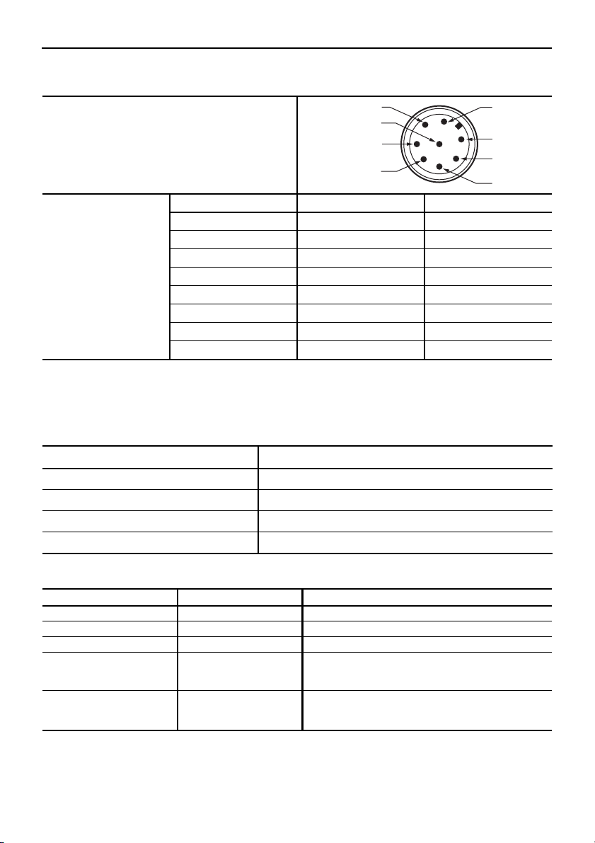
2 24V DC+
1 Aux
7 0V
6 Safety B
3 Lock Command
8 Safety A+
4 Safety B+
5 Safety A
Connections
8-Pin Micro (M12)
Color Function Pin
White Aux 1
Brown 24V DC+ 2
8-Pin Cordset
889D-F8AB-*
or cable version
Green Lock 3
Yellow Safety B+ 4
Grey Safety A 5
Pink Safety B 6
Blue Gnd / 0V 7
Red Safety A+ 8
* Replace symbol with 2 (2 m), 5 (5 m), or 10 (10 m) for standard cable lengths.
Status/Diagnostic LED Indicator
Operating
Status/Diagnostic LED State Meaning
Solid Green Door/Guard closed and locked, safety outputs active.
Solid Red Door/Guard not locked, safety outputs off.
Blinking Red Unit failure. See Troubleshooting, below.
Blinking Green Door/Guard closed and locked, no input signal.
Troubleshooting
Status/Diagnostic LED State Status Troubleshooting
Off Not powered N/A
Solid Green OSSD on N/A
Solid Red OSSD not active N/A
Blinking Green Power up test
Blinking Red 1 Hz Flash: Recoverable fault
or
Safety inputs not present
4 Hz Flash: Non-recoverable fault
For Learn Process LED error codes, see page 12.
10 10000302608 Ver 00 July 2012
Check 24V DC or OSSD inputs (yellow and red wire)
Recoverable fault: Check OSSD. Outputs are not shorted to GND,
24V DC, or each other. Cycle power.
Non-recoverable fault: Cycle power.
Page 11

TLSZR/L-GD2
IMPORTANT
Commissioning
Before use, the switch must first “learn” a new RFID door target. This is not done at the factory, as
there are two options:
• “Multi-Time” learn: the switch can learn up to eight targets consecutively
• “One-Time” learn: the switch can learn just one target, for life, non-reversible*
* ”One-Time” learn can be invoked at any time, not just at commissioning. For example, the
switch could “Multi-Time” learn consecutively four different targets, and then complete a
“One-Time” learn that would prevent it from learning any more targets.
During the learning process the target and actuator must always be
inserted or withdrawn from the switch together in their normal mounting
configuration. If the target is introduced or withdrawn without the
actuator, or the actuator is inserted without the target present, then a
non-recoverable fault condition may occur (requiring a power off-on
cycle).
“Multi-Time” Learn Process
Learning the first “Multi-Time” target
• Connect the switch to 24Vdc (see wiring diagrams on pages 13 through 15).
The Status/Diagnostic LED will blink the number of times a new target may be learned (eight
times when new), and then repeat, indicating that the switch has not yet learned a target.
• The switch will automatically start the learning process as soon as a target and actuator are
placed into the door-closed, locked position of the switch
IMPORTANT
Leave the target/actuator in the door-closed posit ion during the learning
process. If they are removed during the learning process, the ability to
learn an additional target will be disabled.
The learning sequence as indicated by Status/Diagnostic LED:
• Target present: Blinking Green, 1Hz rate
• Verifying target: Blinking Green/Red, 1Hz rate (15 s)
• Programming switch: Blinking Green/Red, 4 Hz rate (15 s)
• Programming finalizing: Blinking Green (number of learns left, 15 sec)
• Ready state (learn is complete): Solid Green (TLSZR), Solid Red (TLSZL)
Learning additional new “Multi-Time” targets
Mount the new target to the door and repeat the above process, introducing the target and
actuator to the switch as described above. During programming finalizing, the LED will blink
Green the number of learns left.
10000302608 Ver 00 July 2012 11
Page 12

TLSZR/L-GD2
“One-Time” Learn Process
• Proceed as the “Multi-Time” learn process above except that at the programming finalizing
stage withdraw the target and actuator away from the switch until the LED turns to solid Red,
then straightaway replace the target and actuator back to the switch. This action must be
completed within 15s *.
• The LED blinks and then turns solid to indicate that learn is complete:
TLSZR: Solid Green
TLSZL: Solid Red
* For power-to-unlock switches, in order to be able to withdraw the target and actuator away
from the switch as described above it will be necessary to execute a manual release.
Status/Diagnostic LED Error Codes During the Learn Process.
These code sequences persist until a power off-on cycle is undertaken.
Status/Diagnostic LED - Flashes (4 Hz) Error Code
Red-Red-Red-Green-Green Target already learned
Red-Red-Red-Green-Green-Green Bad RFID; target moved out of range
Red-Red-Red-Green-Green-Green-Green Exceeded learning eight targets
Red-Red-Red-Green-Green-Green-Green-Green Unit locked to One-Time learn; cannot learn another target
For operating Status/Diagnostic LED codes, see page 10.
12 10000302608 Ver 00 July 2012
Page 13

Wiring Diagrams
Target/Actuator
1
Target/Actuator
2
Target/Actuator
3
Target/Actuator
4
Target/Actuator
5
Switch 1 Switch 2 Switch 3 Switch 4 Switch 5
RTN
24V DC
Power
Supply
+24
1606-
XL120D
Green
Blue
Pink
Grey
Brown
Red
Yel lo w
White
+24V
+24V
Green
Blue
Pink
Grey
Brown
Red
Yellow
White
+24V
+24V
Green
Blue
Pink
Grey
Brown
Red
Yel lo w
White
+0V
+0V
Green
Blue
Pink
Grey
Brown
Red
Yel lo w
White
+0V
+0V
Green
Blue
Pink
Grey
Brown
Red
Yel lo w
White
+0V
+0V
Recoverable
fault
Actuator 1 is in sensing range
and locked.
Switch 1 is funtioning properly.
OSSDs are energized to 24V.
Green LED is ON.
Actuator 2 is in sensing range
and locked.
Switch 2 is funtioning properly.
OSSDs are energized to 24V.
Green LED is ON.
Actuator 3 is in sensing range
and locked.
Switch 3 has a fault.
See Diagnostic table.
Red LED is ashing.
Actuator 4 is in sensing range
and locked.
Switch 4 is functioning properly
Series inputs are 0V.
OSSDs are de-energized to 0V.
Green LED is ashing to indicate
series inputs are not 24V.
Actuator 5 is in sensing range
and locked.
Switch 5 is functioning properly
Series inputs are 0V.
OSSDs are de-energized to 0V.
Green LED is ashing to indicate
series inputs are not 24V.
OSSDs
are OFF
Troubleshooting Series Circuit
TLSZR/L-GD2
10000302608 Ver 00 July 2012 13
Page 14

TLSZR/L-GD2
Target/Actuator 1
Target/Actuator 2
Target/Actuator 3
Switch 1
Switch 2
Switch 3
RTN
24V DC
Power
Supply
+24
1606-
XL120D
Green
Blue
Pink
Grey
Brown
Red
Yel
White
A2
440R-N23132
Initial conditions:
All switches are locked
Switch 1 receives unlock
command (guard door
can then be opened)
Lock/unlock
command
Switch 2 drops the 24 volts (red and
yellow) from Switch 1 OSSD outputs
Green LED ashes
Switch 3 drops the 24 volts (red and
yellow) from Switch 3 OSSD outputs
Green LED ashes
Pink
Grey
Brown
Red
Yel
White
Green
Blue
Pink
Grey
Brown
Red
Yel
White
Green
Blue
S11 41332313S12S52
S21 S22 42342414A1S34
125 ms100 ms75 ms0 ms
650 ms625 ms600 ms0 ms
Switch 1 guard door is
closed
Switch 1 OSSD outputs are
energized
Switch 2 OSSD inputs (red and yellow)
transition to 24V DC from Switch 1
OSSD outputs
Switch 2 OSSD outputs are energized
Switch 3 OSSD inputs (red and
yellow) transition to @$V DC from
Switch 2 OSSD outputs
Switch 3 OSSD outputs are energized
Unit Response Time
(Does not include relay response time)
14 10000302608 Ver 00 July 2012
Page 15

Application Wiring Example
A1
A2
DI
S11
S12
S21
S22
S34
13
23
14
24
0V*
Reset
E-Stop
K1
K2
L11
S32
S42
L12
0
1
2
3
4
5
6
7
8
LOGIC
A1
A2
L11
L12
EMD
X32
*Set for 30 second
OFF Delay (adjustable)
0
1
2
3
4
5
6
7
8
9
RANGE
1
2
3
4
5
6
7
8
9
10
TIME
*
*
Gry
Pnk
Brn
Yel
Red
Blu
Wht
Aux.
TLSZR-GD2
DI = 440R-D22R2
EMD =440R-EM4R2D
Ratings
The safety function initiated by the E-Stop meets the safety performance
requirements of SIL CL3 per IEC 62061:2005 and has a Category 4 structure
that can be used in systems requiring Performance Levels up to PLe per ISO13829-1:2008.
This circuit executes Category 0 stops.
24V*
* Class 2 Power Source
M
K1
K2
External Switched
Stop/Start Circuit
L1
L2
L3
K3
Gate Release
Grn
K3
17
18
K1
K2
TLSZR/L-GD2
10000302608 Ver 00 July 2012 15
Page 16

Power, Control and Information Solutions Headquarters
Americas: Rockwell Automation, 1201 South Second Street, Milwaukee, WI 53204-2496 USA, Tel: (1) 414.382.2000,
Fax: (1) 414.382.4444
Europe/Middle East/Africa: Rockwell Automation NV, Pegasus Park, De Kleetlaan 12a, 1831 Diegem, Belgium,
Tel: (32) 2 663 0600, Fax: (32) 2 663 0640
Asia Pacic: Rockwell Automation, Level 14, Core F, Cyberport 3, 100 Cyberport Road, Hong Kong, Tel: (852) 2887 4788
Fax: (852) 2508 1846
www.rockwel lautomation.com
Copyright © 2012 Rockwell Automation, Inc. All Rights Reserved.
PN-144094
10000302608 Ver 00 July 2012
Printed in USA.
TLSZR/L-GD2
Check the machine is isolated and
stopped whenever the interlocked
guard door is open.
IMPORTANT: After installation and
commissioning, the actuator, switch
and switch lid fixing screws should be
coated with tamper evident varnish or
similar compound.
Declaration of Conformity
Recommended Relays
Guardmaster safety relay family, (440R-D22R2, 440R-D22S2, 440R-S12R2, 440R-S13R2,
440R-GL4S2P, 440R-GL4S2T), MSR 57, MSR126, MSR127, MSR131, MSR138, MSR211, MSR320,
SmartGuard, Safety PLC I/O
Maintenance
Monthly
Check the correct operation of the switching circuit. Also check for signs of abuse or tampering.
Inspect the switch casing for damage
Repair
If there is any malfunction or damage, no attempts at repair should be made. The unit should be
replaced before machine operation is allowed.
Rockwell Automation hereby declares that TLSZR/L-GD2 is in conformity with Directive
2004/108/EC, 2006/42/EC as specified in the Declaration of Conformity available from
www.rockwellautomation.com/products/certification.
 Loading...