

Page 1
SAFEDGE CONTROL UNIT
R
SECD252
(a) SAFEDGE-STEUERGERÄT SECD252
BOITIER DE COMMANDE SAFEDGE SECD252
(b)Installation Instructions
(c )Follow steps 4.1 to 4.5 for correct installation
4.1 24V AC/DC input terminal +ve and -ve
If a 24V AC/DC supply is being used, the supply should be connected to these
terminals, ensuring that the correct polarity is observed. Where a 24V AC or DC
supply is used, it must be isolated from the mains supply in accordance with
international electrical safety pratice (IEC 364-4-41). One pole should be
earthed. For 24V DC the negative pole should be earthed (grounded). With 24V
AC the earthed (grounded) pole of the power supply should be connected to the
-ve terminal.
4.2 Aux Output terminal 21 and 22
This terminal provides an auxiliary normally closed contact (i.e. closed when the
green “Run” light is off) which is suitable for indication or for alarm devices. As
this is an auxiliary, it must not be connected to the safety circuit.
4.3 Safety Output terminal 13 and 14
This is volt free contact for connection to the machine safety circuits i.e, it is
connected in series with the machine contactor control circuit. (Max. rating 2A
at 250V AC). Safety circuit is internally fused but must also be externally
protected with a 2A quick acting fuse.
4.4 Reset terminal X1 - X2
These terminals are used for a number of different functions (supplied without
link). Without the link the terminals can be connected to positively guided
normally closed auxiliary contact on the machine contactor to provide
monitoring of the contactor. Fit a link between these terminals if this function is
not required. This terminal is also used for auto/manual reset. If the X1-X2
terminal is left linked or connected up to the contactors normally closed contact
only, the unit is in automatic reset mode. In automatic reset mode the output is
achieved solely by removal of the actuating force. The output is also achieved at
power up of the actuator (when there is no actuation force present). If a
spontaneous restart may generate a risk, based on the result of a risk assessment
to EN1050, then this mode must not be used. See EN 60204 Pt.1 and EN954
Pt.1. For manual reset mode a normally open spring return (not latching) push
button must be connected across the X1-X2 terminals or in series with the
contactors normally closed. When the actuating force is removed, the unit will
not operate until the button is pressed. The button will also have to be pressed
after power up of the control unit.
4.5 Sensitive edge strip connection to control units
These terminals are used to connect the sensitive edge strip to the: Z1 = Brown (inner conductor).
Z2 = White (outer connector).
NOTE: Sensitive edge strip must be terminated with a 6K8 Resistor (yellow) for
series connection. When two sensitive edge strips are connected directly to Z1
and Z2 (parallel) then each strip should be terminated with a 15K resistor (blue).
Einbauanleitung
Für die korrekte Installation Anweisungen 4.1 bis 4.5 befolgen.
4.1 24 V AC/DC-Eingangsklemmen - positiv und negativ
Bei 24 V AC/DC das Netzkabel an diese Klemmen anschließen und dabei auf
die korrekte Polarität aufpassen. Bei 24 V AC bzw. DC muss die Versorgung
nach den internationalen Vorschriften für elektrische Betriebssicherheit (IEC
364-4-41) vom Netz getrennt werden. Ein Pol sollte geerdet werden. Bei
24V DC sollte der negative Pol geerdet werden. Bei 24 V AC sollte der
geerdete Pol der Stromversorgung an die negative Klemme angeschlossen
werden.
4.2 Hilfsausgangsklemmen 31 und 32
Diese Klemmen sind ein normalerweise geschlossener Hilfskontakt, d.h.
geschlossen, wenn die LED "Betrieb" nicht aufleuchtet. Er ist für den
Anschluss von Anzeigern oder Warnanlagen geeignet. Weil dies ein
Hilfskontakt ist, darf er nicht an den Sicherheitskreis angeschlossen werden.
4.3 Sicherheitsausgangsklemmen 13 und 14
Dies ist ein spannungsfreier Kontakt für den Anschluss an die
Sicherheitskreise, d.h. er wird mit dem Steuerkreis des Maschinenschützes
(max. Nennwert 2 A bei 250 V AC) reihengeschaltet. Der Sicherheitskreis hat
interne Sicherungen, er muss aber außen von einer 2 A Momentsicherung
geschützt werden.
4.4 Rücksetzklemmen X1 - X2
Diese Klemmen werden für eine Reihe von verschiedenen Funktionen
verwendet (ohne Verbindung geliefert). Ohne die Verbindung können die
Klemmen positiv geführt an einen normalerweise geschlossenen Hilfskontakt
des Maschinenschützes angeschlossen werden, um den Schütz zu
überwachen. Diese Klemmen verbinden, wenn diese Funktion nicht
gebraucht wird. Diese Klemme wird auch für automatisches/manuelles
Rücksetzen verwendet. Wenn die Klemme X1-X2 verbunden oder nur an den
normalerweise geschlossenen Kontakt der Schütze angeschlossen ist, wird
das Gerät automatisch zurückgesetzt. Beim automatischen Rücksetzen
entsteht der Ausgang, wenn der Stelldruck eliminiert wird . Der Ausgang
entsteht auch beim Anschalten des Betätigers, wenn kein Stelldruck
vorhanden ist. Wenn Selbstanlassen als das Ergebnis einer Risikobeurteilung
nach DIN EN 1050 eine Gefahr bedeutet, dann darf diese Funktion nicht
verwendet werden, siehe DIN EN 60204, Teil 1 und DIN EN 954, Teil 1. Beim
manuellen Rücksetzen muss ein normalerweise offener (nicht verriegelter)
Taster mit Federrückschlag über den Klemmen X1-X2 angeschlossen oder
mit den normalerweise geschlossenen Schützen reihengeschaltet werden.
Wenn kein Stelldruck vorhanden ist, läuft das Gerät erst dann, wenn der
Taster gedrückt wird. Er muss auch nach dem Anschalten des Steuergerätes
gedrückt werden.
4.5 Anschluss eines Safedge-Prols an das Steuergerät
Diese Klemmen werden verwendet, um das Safedge-Profil an Folgendes
anzuschließen:
Z1 = braun (Leiter innen)
Z2 = weiß (Leiter außen)
HINWEIS: Das Safedge-Profil muss an einen 6K8 Widerstand (gelb) für
Reihenschaltung angeschlossen werden. Wenn zwei Safedge-Profile
unmittelbar an Z1 und Z2 parallel angeschlossen werden, dann sollte jedes
Profil am Ende einen 15K Widerstand (blau) haben.
Notice D'installation
Pour une installation correcte, suivre les ééétapes 4.1 à 4.5.
4.1 Bornes d'alimentation 24 V ca/cc +ve et -ve
Ces bornes sont utilisées lorsque le boîtier est alimenté en 24 V ca/cc en
respectant la polaritéé. Dans ce cas, ne jamais se brancher sur les bornes de 4.2.
Lorsqu'une alimentation en 24 V ca/cc est utilisée, elle doit être isolée de
l'alimentation secteur conforméément aux prescriptions internationales en
matière de sécurité électrique (IEC 364-4-41). Un pôle doit être relié à la terre.
En 24 V cc, le pôle négatif doit être relié à la terre et en 24 V ca, le pôle relié à la
terre doit être connecté sur la borne -ve.
4.2 Bornes de sortie auxiliaire 31 et 32
Ces bornes fournissent un contact auxiliaire normalement fermé (c'est-à-dire
fermé lorsque le témoin vert Run est éteint) qui est destiné au branchement de
dispositifs indicateurs ou d'alarme. Etant donné qu'il s'agit d'un branchement
auxiliaire, ne pas le connecter sur le circuit de sécurité.
4.3 Bornes de sortie de sécurité 13 et 14
Il s'agit de contacts zéro volts destinés à la connexion sur les circuits de sécurité
de la machine, c'est-à-dire qu'ils sont connectés en série avec le circuit de
commande de la machine (2 A maxi. à 250 V ca). Le circuit de sécurité est
protégé par fusible interne mais doit également être protégé extérieurement
par un fusible de 2A à action instantanée.
4.4 Bornes de réarmement X1 et X2
Ces bornes sont utilisées pour différentes fonctions (non connectées). Sans la
connexion, les bornes peuvent être connectées sur des contacts auxiliaires
normalement fermés guidés positivement sur les contacteurs de la machine
pour assurer le contrôle des contacteurs. Si cette fonction n'est pas requise, il
suffit de connecter ces bornes ensemble.
Ces bornes sont également utilisées pour le réarmement automatique ou
manuel. Si les bornes X1-X2 sont laissées connectées ensemble ou connectées
sur des contacteurs à contact normalement fermé uniquement, le boîtier est en
mode automatique. En mode automatique, la sortie est excitée uniquement par
suppression de la force d'activation. Elle est également excitée lors de la mise
sous tension de l'actionneur (en l'absence d'une force d'activation). Si un
redémarrage spontané risque de générer un danger (évaluation des risques
suivant EN 1050), ce mode ne doit pas être utilisé. Voir EN 60204 Pt 1 et EN 954
Pt 1. Pour le mode de réarmement manuel, un bouton poussoir à ressort de
rappel normalement ouvert (sans verrouillage) doit être connecté entre les
bornes X1-X2 ou en série avec les contacteurs normalement fermés. Lorsque la
force d'activation ne s'exerce plus, le boîtier ne fonctionne pas tant que le
bouton est enfoncé. Le bouton doit également être enfoncé après mise sous
tension du boîtier de commande.
4.5 Connexion du prolé sur le boîtier de commande
Ces bornes sont utilisées pour connecter le profilé sur :
Z1 = marron (conducteur intérieur)
Z2 = blanc (conducteur extérieur)
NOTE : Le profilé doit être terminé par une résistance 6K8 (jaune) pour une
connexion en série. Lorsque deux profilés sont connectés directement sur Z1 et
Z2 (en parallèle), chaque profilé doit être terminé par une résistance 15K
(bleue).
Deutsch / Français
1
(a)
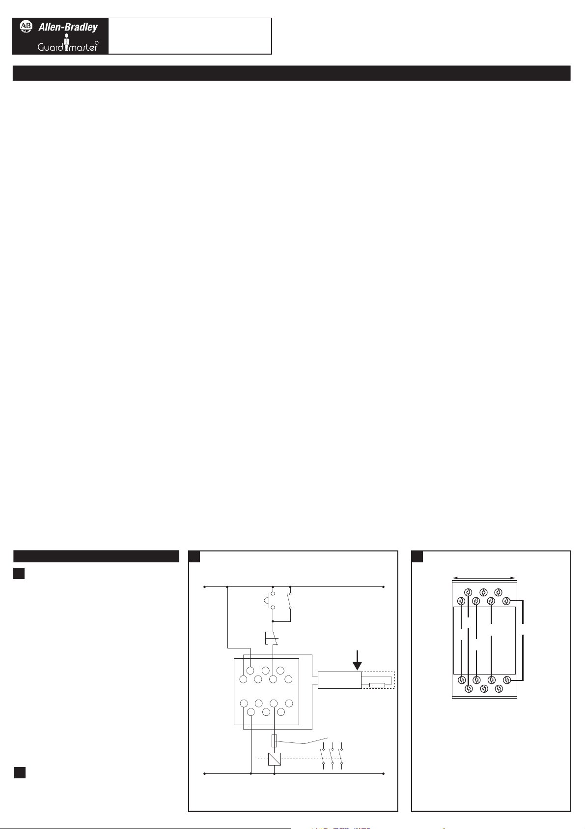
ANWENDUNGSBEISPIEL / Exemple d'application
(b)
24 V DC VERSORGUNG / ALIMENTATION EN 24 V
CC
(c)
START / DEMARRAGE
(d)
FEDERNDER TASTER / BOUTON POUSSOIR A ACTION
MOMENTANEE
(e)
STOPP / ARRET
(f)
SAFEDGE-PROFIL / PROFILE
(g)
6K8 WIDERSTAND / RESISTANCE 6K8
(h)
STEUERGERÄT / BOITIER DE COMMANDE
(i)
SICHERUNG AUSSEN / FUSIBLE EXTERNE
(j)
24 V DC Einsatz mit einem Kontakt, automatisches
Rücksetzen und Start-Stopp-Kreis. X1 und X2
müssen für automatisches Rücksetzen
zusammengeschlossen werden. Hier nicht
verdrahtet! / Application en 24 V cc avec un
contacteur, réarmement automatique et circuit
marche/arrêt
(k)
BRAUN / BRUN
(l)
WEISS / BLANC
2
(a)
ANGABEN ZU DEN ANSCHLËÜSSEN / Détails du
branchement
1
(a) Application example
(b)
24V DC SUPPLY
(c)
START
(d)
MOMENTARY
PUSH BUTTON
(e)
STOP
+
Z1 X1 13
(h)
CONTROL UNIT
Z2
X2
K1
(k)
BROWN
(f)
21
14
22
SENSITIVE
STRIP
-
(l)
WHITE
K1
(j)
24V DC Application with single contact, auto reset and
START/STOP circuit. X1 and X2 must be connected for auto reset.
Not wired here!
(i)
EXTERNAL FUSE
K1
(g)
6K8
RESISTOR
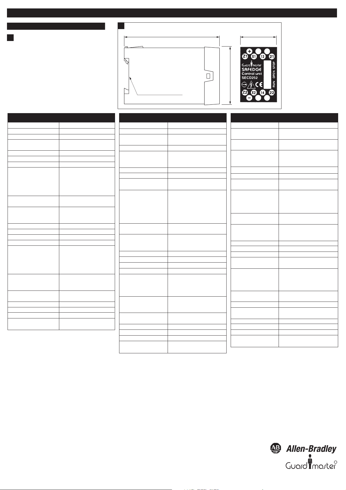
2
(a) Connection details
4.5
22.5
+
Z1 X1 13 21
4.1
4.3 4.2
4.4
Z2 X2
14 22
-
Page 2
(c) Dimensions
Deutsch / Français
3
3
(a) 35 mm DIN-Schienenmontage / MONTAGE SUR RAIL
DIN 35 mm
Technical Specications
Conformity: EN 1760-2, EN 954-1: CATEGORY 3
Power Supply - user select: 24V AC/DC +10% -15%
Power consumption: <4 VA
X1-X2 contactor monitor loop: N/C (normally closed) contactor
loop
Degree of enclosure protection: IP40 DIN0470
Terminal Isolation: IP20 DIN 0470
Min. switched current/voltage: 10mA/10V
Relay outputs: 1 x independent, volt free N/O
safety contact
1 x volt free N/C auxiliary contact
NOTE: Auxiliary should not be used
for safety
Safety inputs: Safedge prole (open resistance
6K8)
Indication Green: RUN
Yellow: OPEN
Red: STOP
Internal fuses: 500mA resettable
Max. output fuse: 4A on AC, 2A on DC
Ambient temp. range -10°C to + 55°C.
Humidity: Up to 90% RH at + 55°C.
Vibration: Tested in accordance with IEC 68-2-
6, frequency range 10 - 55Hz,
displacement 0.15mm. 10 cycles
per axis, sweep rate, 1 octave per
minute
Max. conductor size: 1 x 2.5mm
sleeve to DIN 46228, 1 x 4mm2
solid wire
Terminals: Plus-minus terminal screws M3.5.
Box terminal with wire protection
Installation group: C in accordance with VDE 0110.
Material and colour: Red polycarbonate
Fixing details: 35 mm DIN Rail
Housing: 14 way D=118mm, H=86mm,
W=22.5mm
2
stranded wire with
Konformität: DIN EN 1760-2, DIN EN 954-1: Teil
3
Netzversorgung, vom Benutzer
angewählt: 24 V AC/DC +10% - 15%
Energieverbrauch: <4 VA
X1-X2-MCSchützüberwachungsschleife: normalerweise geschlossene
Schützschleife
Gehäuseschutz: IP40 DIN0470
Klemmenisolierung: IP20 DIN0470
Geschalteter min.
Strom/Spannung: 10 mA/10 V
Relaisausgänge: 1 unabhängiger, spannungsfreier
N/O-Sicherheitskontakt1
spannungsfreier N/C
Hilfskontakt Hinweis: Hilfskontakt darf
nicht als Sicherheitskreis benutzt
werden.
Sicherheitseingänge: Safedge-Prol (oener Widerstand
6K8)
Anzeiger LED 1: Grün: Betrieb
LED 2: Gelb: Oen
LED 3: Rot: Stopp
Interne Sicherungen: 500 mAT ersetzbar
Max. Ausgangssicherung: 4A für AC / 2A für DC
Umgebungstemperatur -10°C bis +55°C
Luftfeuchtigkeit: bis zu 90% RL bei +55oC
Schwingung: Nach IEC 68-2-6 geprüft,
Frequenzbereich10 - 55 Hz,
Versetzung 0,15 mm10 Takte je
Achse, Kipprate 1 Oktave/min
Max. Leiterabmessung: 1x2,5 mm
Isolierung nach DIN 46228 1x4 mm2
fester Draht
Klemmen: Plus-Minus-Klemmschrauben M3.5,
Klemmenkasten mit Drahtschutz
Isolationsklasse: C im Einklang mit VDE 0110
Werksto und Farbe: Rotes Polykarbonat
Befestigung: 35 mm DIN-Schiene
Gehäuse: 14-Wege 118 mm t, 86 mm h, 22,5
mm b, 16-Wege
118
(a) 35MM DIN RAIL MOUNTING
2
Litzendraht, mit
22.5
86
Specications techniquesTechnische Daten
Conformité : EN 1760-2, EN 954-1 : Catégorie 3
Alimentation - réglable par
l'utilisateur : 24V ca/cc + 10% - 15%
Consommation : < 4 VA
Boucle de contrôle contacteur
X1-X2 : N/C (normalement fermé)
Protection boîtier : IP40 DIN 0470
Isolation bornes : IP20 DIN 0470
Intensité/tension mini. de
commutation : 10 mA/10 V
Sortie des relais : 1 contact indépendant de sécurité N/C
zéro volts, 1 contact auxiliaire N/C zéro
volts NOTE : le contact auxiliaire ne doit
pas être utilisé pour la sécurité
Entrées de sécurité : Prolés Safedge (résistance ouverte
6K8)
Témoins : Vert = marche
Jaune = ouvert
Rouge = arrêt
Fusible interne : 500 mA réarmable
Fusible de sortie (maxi.) : 4 A en ca/2A en cc
Plage de températures: - 10 ° à + 55°C
Humidité : jusqu'à 90 % d'humidité relative à +
55°C
Vibrations : Tests suivant IEC 68-2-6, gamme de
fréquences 10-55 Hz, déplacement 0,15
mm. 10 cycles par axe, vitesse de
balayage 1 octave/mn
Section maxi. des conducteurs : 1 x 2,5mm≈ divisé avec gaine, DIN
46228, 1 x 4 mm≈ massif
Bornes : Bornes positives/négatives à vis M3.5.
Bornes tubulaires avec protection de
l.
Groupe d'installation : C suivant VDE 0110
Matériau et coloris : Polycarbonate rouge
Fixations : Rail DIN 35 mm
Dimensions : 118 (P) x 86 (H) x 22,5 mm (L), 14
voies
Drg No: 31646 / Issue No: 1
Change No:
R
 Loading...