

Page 1
Installation Instructions
IMPORTANT: SAVE THESE INSTRUCTIONS FOR FUTURE USE.
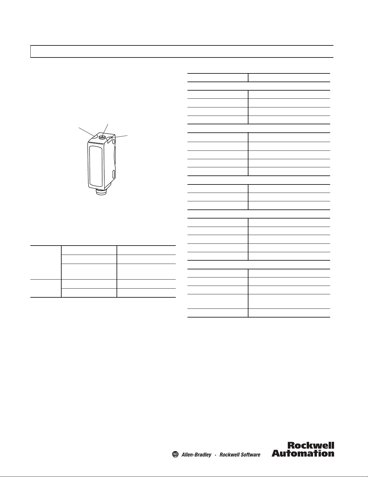
Yel low LED
Pushbutton
Green LED
42JT VisiSight™ Photoelectric Color Mark Sensors
Default Settings:
Output Mode: Light Operate (Output ON when the color mark is
detected after being taught)
Output Type: PNP or NPN (Push-Pull)
Sensor User Interface
LED Status
The table below provides LED status in the RUN mode i.e., during
operation, the sensor is always in RUN mode, except when being
taught.
OFF Power is OFF
Green
Yel l ow *
*LED status shown when the load is connected as PNP. The LED status reverses when the load is
connected as NPN. (e.g. LED is ON when the output is de-energized and OFF when is energized)
Mounting the Sensor
Securely mount the sensor on a firm, stable surface or support.
An application which is subject to excessive vibration or shifting
may cause intermittent operation. For installation convenience,
Rockwell Automation offers a wide range of mounting brackets
(see the Accessories section for more details).
ON Power is ON
Flashing (1.5 Hz)
Output short circuit protection
OFF Output de-energized
ON Output energized
active
General Specifications
42JT-F5LET1-
Environmental
Certifications cULus and CE Marked for all applicable directives
Operating Environment IP67, IP69K
Operating Temperature [C (F)] -20…+60° (-4…+140°)
Storage Temperature [C (F)] -20…+80° (-4…+179°)
Optical
Light Source Visible white LED
Sensing Range [mm (in.)] 12 (0.47)
Tolerance [mm (in.)] +/- 2.5 (+/- 0.1)
Spot Size [mm (in.)] 1 x 4 (0.4 x 0.15)
Adjustments Pushbutton
Electrical
Volt age 10… 30V DC
Current Consumption 25 mA max.
Sensor Protection Reverse polarity, short circuit protection
Outputs
Response Time 50 μs
Output Type PNP or NPN (Push-Pull)
Output Function Selectable light operate or dark operate
Output Current 100 mA max.
Output Leakage Current 10 μA max.
Mechanical
Housing Material ABS
Lens Material PMMA
Cover Material PMMA
Connection Types 2 m PUR cable, 4-pin DC micro (M12) QD on a 150 mm
PUR pigtail, 4-pin pico (M8) integral QD
Optional Accessories Mounting brackets, cordsets
Replace with A2 for 2 m (6.6 ft) cable, F4 for 4-pin DC micro (M12) QD, or P4 on 4-pin DC pico
(M8) QD
UL: -20…+50°C (-4…122°F)
Page 2
Sensor Alignment
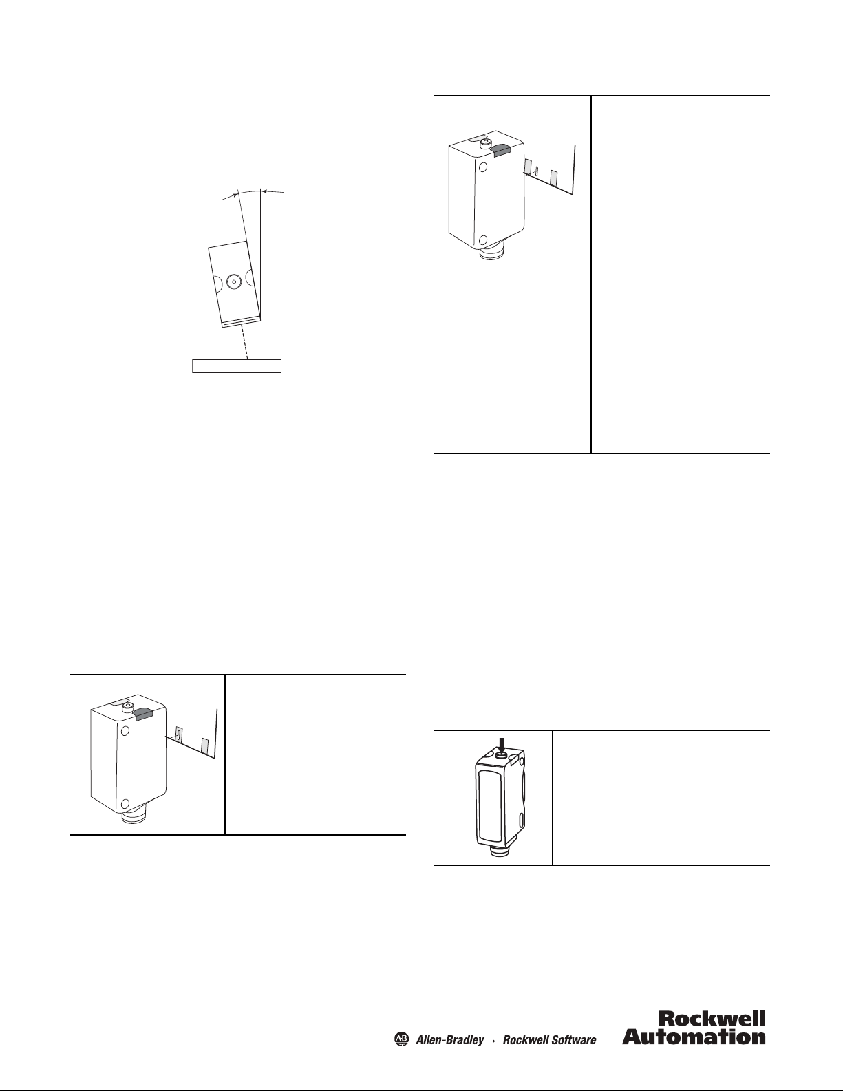
10º
t > 3 s
t < 0.5 s
t > 6 s
Position the 42JT VisiSight contrast sensor so that the distance
from the object to the sensor is 12 mm. High reflectivity surfaces
can impact the reliability of the color mark detection. We
recommend that you angle the sensor 10° to help improve the
color mark detection as shown below.
VisiSight™ Configuration
The 42JT VisiSight is configured using the pushbutton (or Remote
Teach) and the LED indicators on the sensor. There are four
features that can be configured:
• Static Teach
• Dynamic Teach (running process)
• Light operate (LO) or dark operate (DO) output
• Pushbutton lock/unlock
The sensor output is disabled during Teach.
2. Teach the background (second condition).
Present the background to the sensor. Press and
release the button. The teach process is complete.
If the push button is not pressed within 30 seconds,
the sensor exits teach mode and returns to RUN
mode without learning the new setting.
However, if the contrast of the color mark vs. the
background is not sufficient (e.g., a yellow mark on a
white background) the sensor is unable to detect the
color mark. If that is the case, the white LED (light
spot) flashes 10 times.
A flashing white LED (light spot) indicates the
following:
Flashes (10 times): insufficient contrast level
Flashes (3 times): small contrast level
No flashing: good contrast level
If the white LED flashes, angle the sensor 10° (see
“Sensor Alignment,” at left), and repeat the teach
process.
If the sensor is still unable to detect the color mark
and indicates “insufficient contrast level,” a higher
end sensor may be necessary, such as the 45CRM
color mark sensor.
Dynamic Teach (Running Process)
If the targets to be detected are moving with the sensor aimed at
the running process, press and hold the button for three seconds,
until the yellow LED starts flashing. The color mark will
automatically be taught in the next 30 seconds provided the
sensor sees two cycles of mark and background.
Te ac h
Teaching the color mark is a two step process:
1. Teach the color mark (first condition).
Place the sensor 12 mm (0.47 in.) from the color
mark and aim it at the mark. Press and hold the
button for three seconds, until the yellow LED starts
flashing. Release the button.
Although the sensor will operate within a tolerance
of +/-2.5 mm (0.1 in.) from the focal distance, the
sensor should be installed at 12 mm (0.47 in.) for
optimal performance.
Teach Light Operate (L.O.) or Dark Operate (D.O.)
The default setting of the output is Light Operate (L.O.: output ON
when the color mark is detected after being taught.)
If the application requires the output to turn OFF when the color
mark is detected, the setting may be changed to Dark Operate
(D.O.)
1. To access the teach output mode setting:
Press and hold button for six seconds, until green LED starts
flashing. Release the button. The current setting is indicated by
the yellow LED:
L.O.: Yellow LED ON
D.O.: Yello w LED OFF
2
Page 3

2. To change the sensor output mode setting:
M12 Male M8 Male
Output (PNP or NPN) (Push-Pull)
Remote Teach/Lock
+V
-V
?
Brown (1)
White (2)
Black (4)
Blue (3)
t < 0.5 s
Press and release the button within ten seconds to toggle from
L.O. to D.O. , the sele cti on in dica ted by the y ello w LED.
The sensor retains the setting per the last button depression and
returns to the RUN mode ten seconds after the last button is
depressed.
Wiring Diagrams
The quick-disconnect connector is shown in the following
diagrams. The pin numbers correspond to male connectors on
the sensor.
Micro (M12) Male QD on Pigtail and
Integral Pico (M8) Male QD
1
4
2
4
Pushbutton Lock/Unlock
The pushbutton or remote teach (RT) can be used to prevent
unauthorized users from changing teach settings.
To lock th e pushbutton: press and release the button three
times within three seconds. Both LEDs flash synchronously for
three seconds indicating that the pushbutton is now locked.
To unlock the pushbutton: press and release the button three
times within three seconds. Both LEDs flash asynchronously for
three seconds indicating that the pushbutton is now unlocked.
Permanent Lock: The pushbutton may be permanently locked
by connecting the white wire (pin 2) to –V.
Remote Teach (RT)
The sensor can be taught remotely via the white wire (pin 2).
Connection to +V acts the same as the button being pressed and
no connection is the same as the button not being pressed. The
sensor can be taught by following the same teach/timing
sequence as used in the pushbutton teach. For example, connect
to the +V for more than three seconds to align and install the
reflector, disconnect from the +V; while the reflector is in the
sensor’s field of view and there is no target, connect to the +V for
less than one second to complete the teach process. All
pushbutton functions can also be carried out via RT.
1
2
3
Output Wiring
?
Normal operation: no connection.
Remote Teach: connect to +V. Refer to the Remote Teach section.
Pushbutton lock: connect to -V. Refer to the Pushbutton Lock/Unlock section.
Margin Curve
120
100
80
Signal [%]
60
3
3
0
7171615141312111098
Distance [mm]
Page 4

Power, Control and Information Solutions Headquarters
Americas: Rockwell Automation, 1201 South Second Street, Milwaukee, WI 53204-2496 USA, Tel: (1) 414.382.2000, Fax: (1) 414.382.4444
Europe/Middle East/Africa: Rockwell Automation NV, Pegasus Park, De Kleetlaan 12a, 1831 Diegem, Belgium, Tel: (32) 2 663 0600, Fax: (32) 2 663 0640
Asia Pacic: Rockwell Automation, Level 14, Core F, Cyberport 3, 100 Cyberport Road, Hong Kong, Tel: (852) 2887 4788, Fax: (852) 2508 1846
www.rockwel lautomation.com
Approximate Dimensions [mm (in.)]
12
(0.47)
M8 x 1
34
(1.34)
22.9
(0.90)
25.4
(1.0)
2.6
(0.10)
20
(0.79)
12
(0.47)
34
(1.34)
22.9
(0.90)
25.4
(1.0)
2.6
(0.10)
20
(0.79)
2.8
(0.11)
Clearance for
M3 or #4-40 screw
(2 places)
Clearance for
M3 or #4-40 screw
(2 places)
Accessories
Stainless Steel Mounting Brackets
60-BJS-L1
°
15
8 (0.32)
24
(0.95)
60-BJT-L2
14
(0.55)
30°
12
(0.47)
R 25.4
(R 1.0)
18.6
(0.73)
33
(1.3)
63.5
(2.5)
8
(0.32)
14
(0.55)
20°
R 25.4
(1.0)
10°
12
(0.47)
18.6
(0.73)
33
(1.3)
Copyright © 2012 Rockwell Automation, Inc. All Rights Reserved. 10000234774 Ver 01
December 2012
Printed in Germany
068-14494
 Loading...