

Page 1
Installation Instructions
Solar Visor Accessory
Catalog Number 2711P-RVT12
Language Page
English 3
Français 5
Deutsch 7
Español 11
Italiano 9
Português 13
Publication 2711P-IN025C-MU-P - March 2007
Page 2
2 Solar Visor Accessory
Important User Information
Solid state equipment has operational characteristics differing from those of electromechanical equipment.
Safety Guidelines for the Application, Installation and Maintenance of Solid State Controls (publication
SGI-1.1 available from your local Rockwell Automation sales office or online at
http://literature.rockwellautomation.com
equipment and hard-wired electromechanical devices. Because of this difference, and also because of the
wide variety of uses for solid state equipment, all persons responsible for applying this equipment must
satisfy themselves that each intended application of this equipment is acceptable.
In no event will Rockwell Automation, Inc. be responsible or liable for indirect or consequential damages
resulting from the use or application of this equipment.
The examples and diagrams in this manual are included solely for illustrative purposes. Because of the many
variables and requirements associated with any particular installation, Rockwell Automation, Inc. cannot
assume responsibility or liability for actual use based on the examples and diagrams.
No patent liability is assumed by Rockwell Automation, Inc. with respect to use of information, circuits,
equipment, or software described in this manual.
Reproduction of the contents of this manual, in whole or in part, without written permission of Rockwell
Automation, Inc., is prohibited.
Throughout this manual, when necessary, we use notes to make you aware of safety considerations.
) describes some important differences between solid state
WARNING
IMPORTANT
ATTENTION
SHOCK HAZARD
BURN HAZARD
Identifies information about practices or circumstances that can cause an explosion in
a hazardous environment, which may lead to personal injury or death, property
damage, or economic loss.
Identifies information that is critical for successful application and understanding of
the product.
Identifies information about practices or circumstances that can lead to personal injury
or death, property damage, or economic loss. Attentions help you to identify a hazard,
avoid a hazard, and recognize the consequences.
Labels may be on or inside the equipment, for example, a drive or motor, to alert
people that dangerous voltage may be present.
Labels may be on or inside the equipment, for example, a drive or motor, to alert
people that surfaces may reach dangerous temperatures.
Publication 2711P-IN025C-MU-P - March 2007
Page 3
Installation Instructions
Solar Visory Accessory
Catalog Number 2711P-RVT12
English
Overview
This accessory is recommended for use with the PanelView Plus 1250 or PanelView
Plus CE 1250 touch outdoor high-bright display.
The accessory kit includes:
• Solar visor (1)
• Visor clips (3)
• Locking nuts, M4 (6)
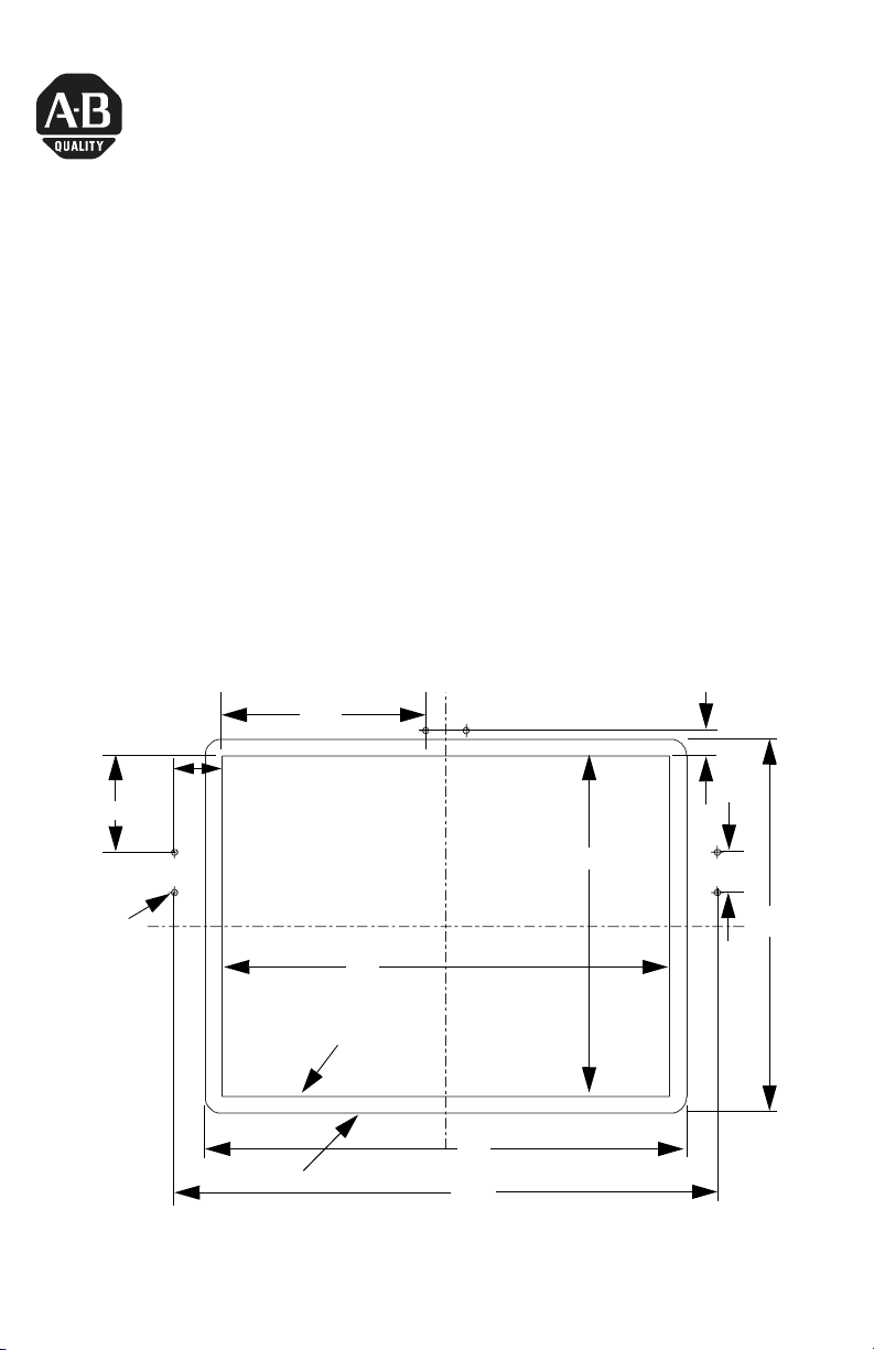
Install the Visor
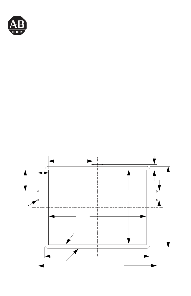
1. Drill six holes, 4.8 mm (0.188 in.) as indicated.
153.5 (6.05)
19.3 (0.76)
36
(1.42)
72.5 (2.86)
Ø4.8
(0.188)
Panel Cut-Out
Bezel Outline
338
(13.29)
257
(10.11)
363 (14.30)
409.5 (16.12)
Publication 2711P-IN025C-MU-P - March 2007
30.5 (1.20)
282
(11.12)
Page 4
4 Solar Visory Accessory
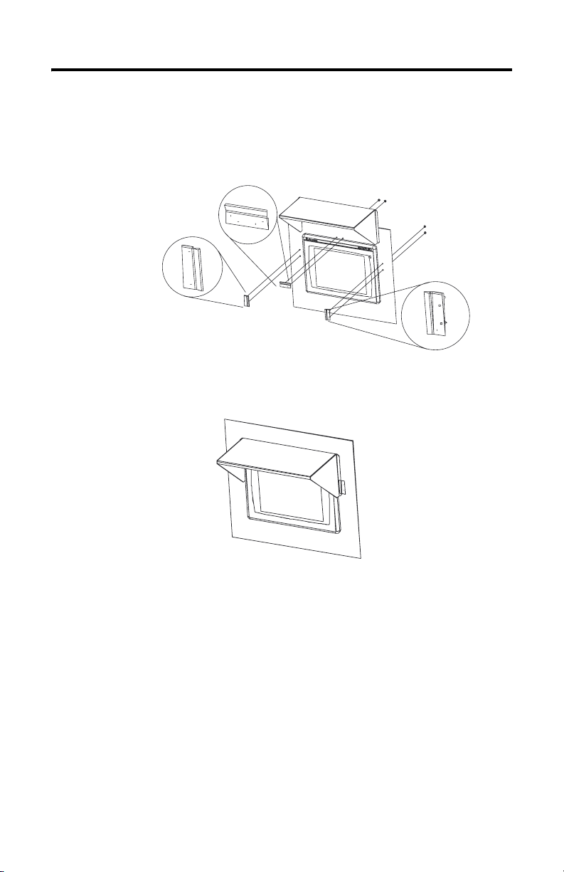
2. Insert visor clips through holes and secure each clip with two M4
self-locking nuts supplied.
Torque to 1.13 Nm (10 lb-in). See illustration below for proper visor clip
orientation.
Visor Clips
Solar Visor
3. Slide the solar visor down on to the unit.
The clips hold the visor in place.
Locking Nuts
Publication 2711P-IN025C-MU-P - March 2007
Page 5
Notice d’installation
Pare-soleil
Référence 2711P-RVT12
Français
Présentation
Cet accessoire est à utiliser sur le terminal haute intensité à dalle tactile
PanelView Plus 1250 ou PanelView Plus CE 1250 (utilisation à l’extérieur).
Le kit inclut :
• un pare-soleil ;
• trois attaches de fixation pour le pare-soleil ;
• six écrous autobloquants M4.
Installation
1. Percez six trous de 4,8 mm comme indiqué dans le schéma ci-dessous.
153,5
36
19,3
72,5
Ø4,8
338
Découpe du panneau
Cadre de la face avant
257
363
409,5
Publication 2711P-IN025C-MU-P - March 2007
30,5
282
Page 6

6 Pare-soleil
2. Insérez les attaches dans les trous et fixez-les avec deux écrous
autobloquants M4 (fournis).
Serrez avec un couple de 1,13 Nm. Reportez-vous à l’illustration ci-dessous
pour vérifier l’orientation des attaches.
Attaches du pare-soleil
Pare-soleil
3. Faites glisser le pare-soleil sur l’unité.
Les attaches maintiennent le pare-soleil en place.
Ecrous autobloquants
Publication 2711P-IN025C-MU-P - March 2007
Page 7

Installationsanleitung
Schirmblende - Zubehörteil
Bestellnummer 2711P-RVT12
Deutsch
Überblick
Dieses Zubehörteil wird für die Verwendung mit PanelView Plus 1250 oder dem
PanelView Plus CE 1250 Touch mit hoher Leuchtkraft (High-Bright-Ausführung)
bei Outdoor-Einsatz empfohlen.
Das Zubehör-Kit umfasst folgende Elemente:
• Schirmblende (1)
• Blendenklammern (3)
• Verriegelungsmuttern, M4 (6)
Installation
1. Bohren Sie sechs Löcher mit einer Größe von 4,8 mm wie in der Abbildung
gezeigt.
153,5
19,3
72,5
Ø 4,8
36
30,5
282
Schaltschrankausschnitt
Einbaurand
257
338
363
409,5
Publication 2711P-IN025C-MU-P - March 2007
Page 8

8 Schirmblende - Zubehörteil
2. Stecken Sie die Blendenklammern in die Löcher, und befestigen Sie jede
Klammer mit zwei selbstsichernden Verriegelungsmuttern vom Typ M4.
Die entsprechenden Muttern sind im Lieferumfang enthalten. Drehen Sie sie
mit 1,13 Nm fest. In der Abbildung unten sehen Sie die korrekte Ausrichtung
der Blendenklammern.
Blendenklammern
Schirmblende
3. Schieben Sie die Schirmblende auf das Gerät.
Die Klammern verhindern ein Verrutschen der Schirmblende.
Verriegelungsmuttern
Publication 2711P-IN025C-MU-P - March 2007
Page 9

Istruzioni per l’installazione
Accessorio parasole
Numero di catalogo 2711P-RVT12
Italiano
Panoramica
Si consiglia di utilizzare questo accessorio con il display per uso esterno
High-Bright Touchscreen PanelView Plus 1250 o PanelView Plus CE 1250.
Il kit comprende:
• Parasole (1)
• Clip per parasole (3)
• Dadi autobloccanti, M4 (6)
Installazione
4. Eseguire sei fori da 4,8 mm come indicato.
72,5
Ø 4,8
36
153,5
Cornice
338
Apertura pannello
19,3
257
363
409,5
Publication 2711P-IN025C-MU-P - March 2007
30,5
282
Page 10

10 Accessorio parasole
5. Inserire le clip nei fori e fissarle con due dadi autobloccanti M4 forniti.
Stringere con una coppia di 1,13 Nm (10 poll.-lb). Vedere l'illustrazione di
sotto per il corretto orientamento delle clip.
Clip parasole
6. Fare scorrere il parasole verso il basso.
Le clip mantengono il parasole in posizione.
Parasole
Dadi autobloccanti
Publication 2711P-IN025C-MU-P - March 2007
Page 11

Instrucciones de instalación
Parasol
Número de catálogo 2711P-RVT12
Español
Descripción general
Se recomienda utilizar este accesorio con la pantalla táctil de alto brillo para
exteriores PanelView Plus 1250 o PanelView Plus CE 1250.
El juego de accesorios incluye:
• Parasol (1)
• Abrazaderas del parasol (3)
• Contratuercas, M4 (6)
Instalación
1. Taladre seis orificios de 4.8 mm (0.188 pulg.)
Como se indica en la ilustración.
153.5 (6.05)
36
(1.42)
72.5 (2.86)
19.3 (0.76)
Ø4.8
(0.188)
338
(13.29)
Corte de panel
Contorno del bisel
257
(10.11)
363 (14.30)
409.5 (16.12)
Publication 2711P-IN025C-MU-P - March 2007
30.5 (1.20)
282
(11.12)
Page 12

12 Parasol
2. Introduzca las abrazaderas del parasol por los orificios y fíjelas con las dos
contratuercas M4 suministradas.
Aplique par de apriete de hasta 1.13 Nm (10 pulg.-lb). En la ilustración
siguiente puede consultar la orientación correcta de las abrazaderas del
parasol.
Abrazaderas del parasol
3. Deslice el parasol sobre la unidad.
Las abrazaderas fijan el parasol.
Parasol
Contratuercas
Publication 2711P-IN025C-MU-P - March 2007
Page 13

Instruções de instalação
Acessório visor solar
Código de catálogo 2711P-RVT12
Português
Características gerais
Este acessório é recomendado para uso com a tela PanelView Plus 1250 ou
PanelView Plus CE 1250 Touch Outdoor High-Bright.
O kit de acessórios inclui:
• Visor solar (1)
• Clipes do visor (3)
• Porcas de travamento, M4 (6)
Instalação
1. Fure seis orifícios de 4,8 mm (0,188 pol.) conforme indicado.
153,5 (6,05)
36
(1,42)
72,5 (2,86)
19,3 (0,76)
Ø4,8
(0,188)
338
(13,29)
Corte do painel
Contorno da moldura
257
(10,11)
363 (14,30)
409,5 (16,12)
Publication 2711P-IN025C-MU-P - March 2007
30,5 (1,20)
282
(11,12)
Page 14

14 Acessório visor solar
2. Insira os clipes do visor nos orifícios e prenda cada clipe com duas porcas
M4 de autotravamento (fornecidas).
Aperte com um torque de 1,13 Nm (10 pol-lb). A figura abaixo mostra o
posicionamento correto do clipe do visor.
Clipes do visor
Visor solar
3. Deslize o visor solar para baixo na unidade.
Os clipes prendem o visor na posição.
Porcas de travamento
Publication 2711P-IN025C-MU-P - March 2007
Page 15

Page 16

Rockwell Automation Support
Rockwell Automation provides technical information on the Web to assist you in
using its products. At http://support.rockwellautomation.com
technical manuals, a knowledge base of FAQs, technical and application notes,
sample code and links to software service packs, and a MySupport feature that you
can customize to make the best use of these tools.
For an additional level of technical phone support for installation, configuration,
and troubleshooting, we offer TechConnect Support programs. For more
information, contact your local distributor or Rockwell Automation representative,
or visit http://support.rockwellautomation.com
.
Installation Assistance
If you experience a problem with a hardware module within the first 24 hours of
installation, please review the information that's contained in this manual. You can
also contact a special Customer Support number for initial help in getting your
module up and running.
, you can find
United States 1.440.646.3223
Outside United
States
Monday – Friday, 8am – 5pm EST
Please contact your local Rockwell Automation representative for any
technical support issues.
New Product Satisfaction Return
Rockwell tests all of its products to ensure that they are fully operational when
shipped from the manufacturing facility. However, if your product is not
functioning, it may need to be returned.
United States Contact your distributor. You must provide a Customer Support case number
Outside United
States
Allen-Bradley, PanelView, TechConnect, and Rockwell Automation are trademarks of Rockwell Automation, Inc.
Trademarks not belonging to Rockwell Inc. are property of their respective companies.
Publication 2711P-IN025C-MU-P - March 2007 PN 41061-357-01(3)
Supersedes Pub lication 2711P-IN025B-M U-P - November 2004 Copyright © 20 07 Rockwell Automati on, Inc. All rights reser ved. Printed in the U.S.A.
(see phone number above to obtain one) to your distributor in order to
complete the return process.
Please contact your local Rockwell Automation representative for return
procedure.
 Loading...