

Page 1

Installation Instructions
Mounting Clips
Catalog Number 2711P-RTMC
Language Page
English 3
Français 5
Deutsch 7
Español 9
Italiano 11
Português 13
Publication 2711P-IN006B-MU-P - March 2007
Page 2
2 Mounting Clips
Important User Information
Solid state equipment has operational characteristics differing from those of electromechanical equipment.
Safety Guidelines for the Application, Installation and Maintenance of Solid State Controls (publication
SGI-1.1 available from your local Rockwell Automation sales office or online at
http://literature.rockwellautomation.com
equipment and hard-wired electromechanical devices. Because of this difference, and also because of the
wide variety of uses for solid state equipment, all persons responsible for applying this equipment must
satisfy themselves that each intended application of this equipment is acceptable.
In no event will Rockwell Automation, Inc. be responsible or liable for indirect or consequential damages
resulting from the use or application of this equipment.
The examples and diagrams in this manual are included solely for illustrative purposes. Because of the many
variables and requirements associated with any particular installation, Rockwell Automation, Inc. cannot
assume responsibility or liability for actual use based on the examples and diagrams.
No patent liability is assumed by Rockwell Automation, Inc. with respect to use of information, circuits,
equipment, or software described in this manual.
Reproduction of the contents of this manual, in whole or in part, without written permission of Rockwell
Automation, Inc., is prohibited.
Throughout this manual, when necessary, we use notes to make you aware of safety considerations.
) describes some important differences between solid state
WARNING
IMPORTANT
ATTENTION
SHOCK HAZARD
BURN HAZARD
Identifies information about practices or circumstances that can cause an explosion in
a hazardous environment, which may lead to personal injury or death, property
damage, or economic loss.
Identifies information that is critical for successful application and understanding of
the product.
Identifies information about practices or circumstances that can lead to personal injury
or death, property damage, or economic loss. Attentions help you to identify a hazard,
avoid a hazard, and recognize the consequences.
Labels may be on or inside the equipment, for example, a drive or motor, to alert
people that dangerous voltage may be present.
Labels may be on or inside the equipment, for example, a drive or motor, to alert
people that surfaces may reach dangerous temperatures.
Publication 2711P-IN006B-MU-P - March 2007
Page 3

Installation Instructions
Mounting Clips
Catalog Number 2711P-RTMC
English
About This Publication
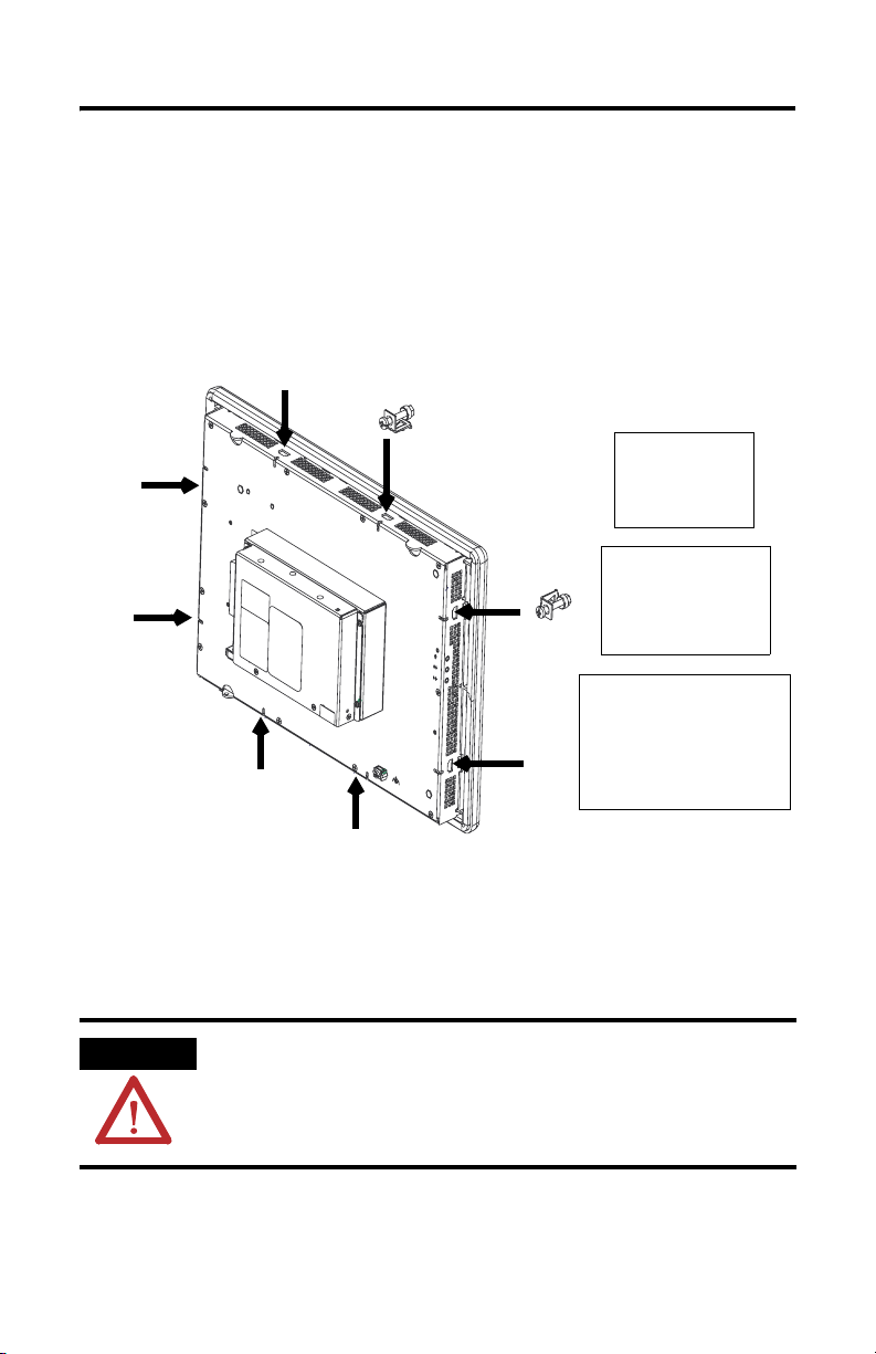
This document provides instructions on how to install the following devices in a
panel or enclosure using the 2711P-RTMC mounting clips. Eight mounting clips are
provided with kit.
• 2711P PanelView Plus terminal
• 2711P PanelView Plus CE terminal
• RAC6182 industrial computer
The mounting clips hold the device tightly against the mounting enclosure. The
number clips used for installation varies by device.
Number
of Clips
Device Clip Location on Device
RAC6182 (all sizes)
4
PanelView Plus and PanelView Plus CE 700 (all versions)
PanelView Plus and PanelView Plus CE 1000 Touch Only
PanelView Plus and PanelView Plus CE 1000 Keypad or
6
Keypad & Touch
PanelView Plus and PanelView Plus CE 1250 (all versions)
8 PanelView Plus and PanelView Plus CE 1500 (all versions)
Publication 2711P-IN006B-MU-P - March 2007
Top: left and right slots
Bottom: left and right slots
Top: left and right slots
Bottom: left and right slots
Sides: left and right slots
Top: left and right slots
Bottom: left and right slots
Sides: top and bottom
Page 4
4 Mounting Clips
Install the Mounting Clips
Follow these steps to install the mounting clips.
1. Install the mounting clips on the terminal.
The ends of the clips slide into the slots on the terminal. Tighten the
mounting clip screws by hand until the gasket seal contacts the mounting
surface uniformly.
The recommended torque sequences
are shown below.
14
3
4 Clips
2
513
6 Clips
246
1
3
7
5
8 Clips
6
8
4
2
2. Alternately tighten the mounting clip screws to a torque of:
• 1.13 Nm (10 lb-in) for the RAC6182 device.
• 0.90…1.1 Nm (8…10 lb-in) for the 2711P PanelView Plus or PanelView
Plus CE device.
Do not overtighten.
ATTENTION Tighten the mounting clips to the recommended torque to provide a proper seal
and to prevent damage to the device. Allen-Bradley assumes no responsibility
for water or chemical damage to the product or other equipment within the
enclosure because of improper installation.
Publication 2711P-IN006B-MU-P - March 2007
Page 5

Notice d’installation
Colliers de fixation
Référence 2711P-RTMC
Français
Présentation
Le présent document indique comment installer les équipements suivants sur un
panneau ou dans une armoire à l’aide de colliers de fixation 2711P-RTMC. Un kit
contient huit colliers de fixation.
• PanelView Plus 2711P ;
• PanelView Plus CE 2711P ;
• station industrielle RAC6182.
Les colliers de fixation permettent de maintenir le terminal contre le support de
montage. Le nombre de colliers à utiliser varie selon l’équipement.
Nombre
de
colliers
Equipement
RAC6182 (toutes tailles)
PanelView Plus/PanelView Plus CE 700 (toutes versions)
4
PanelView Plus/PanelView Plus CE 1000 à écran tactile
uniquement
PanelView Plus/PanelView Plus CE 1000 à clavier ou
6
à clavier et écran tactile
PanelView Plus/PanelView Plus CE 1250 (toutes versions)
8 PanelView Plus/PanelView Plus CE 1500 (toutes versions)
Emplacement des colliers sur
l’équipement
Haut : encoches gauche et droite
Bas : encoches gauche et droite
Haut : encoches gauche et droite
Bas : encoches gauche et droite
Côtés : encoches gauche et droite
Haut : encoches gauche et droite
Bas : encoches gauche et droite
Côtés : encoches supérieure et
inférieure
Publication 2711P-IN006B-MU-P - March 2007
Page 6

6 Colliers de fixation
Mise en place des colliers de fixation :
1. Mettez les colliers de fixation en place sur le terminal.
Les extrémités des colliers s’insèrent dans les encoches situées sur le
terminal. Serrez les vis des colliers de fixation à la main jusqu’à ce que le
joint soit comprimé uniformément contre la surface de montage.
Les séquences de serrage recommandées
sont indiquées ci-dessous.
14
3
4 colliers
2
513
6 colliers
246
1
6
3
8 colliers
7
5
2
2. Serrez les vis des colliers de fixation l’une après l’autre, avec un couple de :
• 1,13 Nm pour la station RAC6182 ;
• 0,90 à 1,1 Nm pour les PanelView Plus 2711P et les PanelView
Plus CE 2711P.
Veillez à ne pas trop les serrer.
ATTENTION
Serrez les vis au couple recommandé pour assurer une bonne étanchéité et
éviter d’endommager l’équipement. Allen-Bradley ne saurait être tenu pour
responsable des dégâts causés par une infiltration d’eau ou de produit
chimique dans l’équipement ou dans tout autre équipement présent dans
l’armoire, suite à une installation incorrecte.
8
4
Publication 2711P-IN006B-MU-P - March 2007
Page 7

Installationsanleitung
Montageklammern
Bestellnummer 2711P-RTMC
Deutsch
Überblick
Dieses Dokument enthält Anleitungen zur Montage der folgenden Geräte in einem
Schaltschrank oder Gehäuse mit Hilfe der Montageklammern 2711P-RTMC. Ein
Bausatz enthält acht Montageklammern.
• 2711P PanelView Plus
• 2711P PanelView Plus CE
• RAC6182-Industriecomputer
Die Montageklammern befestigen das Terminal fest am Montagegehäuse. Die
Anzahl der für die Montage zu verwendenden Klammern hängt vom jeweiligen
Gerät ab.
Anzahl
der
Klam-
mern
Gerät
RAC6182 (alle Größen)
4
PanelView Plus/PanelView Plus CE 700 (alle Versionen)
PanelView Plus/PanelView Plus CE 1000 (nur Touchscreen)
PanelView Plus/PanelView Plus CE 1000 (Keypad oder
6
Keypad & Touchscreen)
PanelView Plus/PanelView Plus CE 1250 (alle Versionen)
8 PanelView Plus/PanelView Plus CE 1500 (alle Versionen)
Publication 2711P-IN006B-MU-P - March 2007
Position der Klammern am
Gerät
Oben: Schlitze links uns rechts
Unten: Schlitze links uns rechts
Oben: Schlitze links uns rechts
Unten: Schlitze links uns rechts
Seitlich: Schlitze links uns rechts
Oben: Schlitze links uns rechts
Unten: Schlitze links uns rechts
Seitlich: Oben und unten
Page 8

8 Montageklammern
Zum Installieren der Montageklammern wie folgt vorgehen:
1. Die Montageklammern am Terminal befestigen. Die Anzahl der Klammern
hängt vom jeweiligen Gerät ab.
Die empfohlene Anzugsreihenfolge
ist im Folgenden abgebildet.
14
4
Klammern
3
513
6
Klammern
246
2
1
3
Klammern
7
5
2. Ziehen Sie die Schrauben der Montageklammern abwechselnd mit
folgendem Anzugsdrehmoment fest:
• 1,13 Nm für RAC6182
• 0,90…1,1 Nm für PanelView Plus 2711P und PanelView Plus CE 2711P
Ziehen Sie die Schrauben nicht zu fest an.
ACHTUNG
Ziehen Sie die Montageklammern mit dem empfohlenen Anzugsdrehmoment
fest, um eine ausreichende Dichtigkeit zu gewährleisten und mögliche Schäden
am Gerät zu vermeiden. Rockwell Automation übernimmt keine Haftung für
Schäden, die durch Wasser oder Chemikalien am Gerät oder an anderen
Geräten innerhalb des Gehäuses entstehen und auf eine falsche Installation
zurückzuführen sind.
6
8
8
4
2
Publication 2711P-IN006B-MU-P - March 2007
Page 9

Instrucciones de Instalación
Sujetadores de montaje
Número de catálogo 2711P-RTMC
Español
Descripción general
Este documento proporciona instrucciones sobre cómo instalar los siguientes
dispositivos en un panel o envolvente, usando los sujetadores de montaje
2711P-RTMC. Cada juego incluye ocho sujetadores de montaje.
• 2711P PanelView Plus
• 2711P PanelView Plus CE
• Computadora industrial RAC6182
Los sujetadores de montaje acoplan firmemente el terminal al envolvente de
montaje. El número de sujetadores que se usa para la instalación varía
dependiendo del dispositivo.
Número
de
sujeta-
dores
4
6
8
Dispositivo
RAC6182 (todos los tamaños)
PanelView Plus/PanelView Plus CE 700 (todas las
versiones)
PanelView Plus/PanelView Plus CE 1000 de pantalla táctil
solamente
PanelView Plus/PanelView Plus CE 1000 de techado o
teclado y pantalla táctil
PanelView Plus/PanelView Plus CE 1250 (todas las
versiones)
PanelView Plus/PanelView Plus CE 1500 (todas las
versiones)
Publication 2711P-IN006B-MU-P - March 2007
Ubicación del sujetador en el
dispositivo
Parte superior: Ranuras izquierda
y derecha
Parte inferior: Ranuras izquierda y
derecha
Parte superior: Ranuras izquierda
y derecha
Parte inferior: Ranuras izquierda y
derecha
Lados: Ranuras izquierda y
derecha
Parte superior: Ranuras izquierda
y derecha
Parte inferior: Ranuras izquierda y
derecha
Lados: Parte superior y parte
inferior
Page 10

10 Sujetadores de montaje
Cómo instalar los sujetadores de montaje:
1. Instale los sujetadores de montaje en el terminal. El número de sujetadores
varía para cada dispositivo.
Los extremos de los sujetadores se deslizan dentro de las ranuras en el
terminal. Apriete manualmente los tornillos de los sujetadores de montaje
hasta que el sello de la empaquetadura haga contacto con la superficie de
montaje de manera uniforme.
Las secuencias de par de apriete
se muestran a continuación.
14
4 sujetadores de
montaje
3
513
6 sujetadores de
montaje
246
2
1
3
8 sujetadores de montaje
7
5
2. Como alternativa, apriete los tornillos de los sujetadores de montaje a un
par de:
• 1.13 Nm (10 lbs-pulg.) para RAC6182
• 0.90…1.1 Nm (8…10 lbs-pulg.) para PanelView Plus 2711P y PanelView
Plus CE 2711P
3. No sobreapriete.
ATENCIÓN
Apriete los sujetadores de montaje al par recomendado para proporcionar un
sello adecuado y para evitar dañar el dispositivo. Allen-Bradley no asumirá
ninguna responsabilidad por los daños causados por agua u otros productos
químicos que puedan sufrir el dispositivo u otros equipos dentro del envolvente
debido a una instalación incorrecta.
Publication 2711P-IN006B-MU-P - March 2007
6
8
4
2
Page 11

Istruzioni per I’installazione
Clip di montaggio
Numero di catalogo 2711P-RTMC
Italiano
Panoramica
Questo documento descrive come installare i seguenti dispositivi su un pannello o
in una custodia utilizzando le clip di montaggio 2711P-RTMC. Il kit contiene otto
clip di montaggio.
• PanelView Plus 2711P
• PanelView Plus CE 2711P
• Computer industriale RAC6182
Le clip di montaggio servono a bloccare il terminale sulla custodia di montaggio. Il
numero di clip utilizzate varia in base al tipo di dispositivo
Numero
di clip
Dispositivo
RAC6182 (tutte le dimensioni)
4
PanelView Plus/PanelView Plus CE 700 (tutte le versioni)
PanelView Plus/PanelView Plus CE 1000 solo Touch Screen
PanelView Plus/PanelView Plus CE 1000 solo tastierino
6
numerico o tastierino e touchscreen
PanelView Plus/PanelView Plus CE 1250 (tutte le versioni)
8 PanelView Plus/PanelView Plus CE 1500 (tutte le versioni)
Publication 2711P-IN006B-MU-P - March 2007
Posizione della clip sul
dispositivo
In alto: fori di sinistra e di destra
In basso: fori di sinistra e di destra
In alto: fori di sinistra e di destra
In basso: fori di sinistra e di destra
Ai lati: fori di sinistra e di destra
In alto: fori di sinistra e di destra
In basso: fori di sinistra e di destra
Ai lati: In alto e in basso
Page 12

12 Clip di montaggio
A
Per installare le clip di montaggio:
1. Installare le clip di montaggio sul terminale. Il numero di clip varia per
ciascun dispositivo.
Le estremità delle clip vanno inserite nei fori presenti sul terminale. Avvitare
a mano le viti delle clip di montaggio fino a quando la guarnizione risulta
completamente aderente alla superficie di montaggio.
Sequenze di avvitamento
consigliate.
14
4 clip
3
6 clip
2
513
246
1
3
7
5
8 clip
6
8
4
2
2. Stringere alterntivamente le viti delle clip di montaggio con una coppia di:
• 1,13 Nm (10 pollici-libbra) per il RAC6182
• 0,90…1,1 Nm (8…10 pollici-libbra) per PanelView Plus 2711P e
PanelView Plus CE 2711P
Non stringere troppo.
TTENZIONE
Avvitare le clip di montaggio secondo la coppia consigliata per fornire una
tenuta corretta ed evitare danni al dispositivo. Allen-Bradley non è
responsabile per eventuali danni causati da acqua o agenti chimici al
dispositivo o ad altre apparecchiature all'interno della custodia dovuti ad
un'installazione errata.
Publication 2711P-IN006B-MU-P - March 2007
Page 13

Instruções de Instalação
Clipes de Montagem
Código de Catálogo 2711P-RTMC
Português
Características Gerais
Este documento fornece instruções sobre como instalar os dispositivos a seguir em
um painel ou gabinete utilizando clipes de montagem 2711P-RTMC. São fornecidos
oito clipes de montagem com o conjunto.
• 2711P PanelView Plus
• 2711P PanelView Plus CE
• Computador Industrial RAC6182
Os clipes de montagem fixam o terminal ao gabinete de montagem. O número de
clipes utilizados para instalação varia de acordo com o dispositivo
Número
de
Clipes
Dispositivo Local do Clip no Dispositivo
RAC6182 (todos os tamanhos)
4
PanelView Plus/PanelView Plus CE 700 (todas as versões)
PanelView Plus/PanelView Plus CE 1000 Touch Only
PanelView Plus/Teclado PanelView Plus CE 1000 ou
6
Teclado e Touchscreen
PanelView Plus/PanelView Plus CE 1250 (todas as versões)
8 PanelView Plus/PanelView Plus CE 1500 (todas as versões)
Publication 2711P-IN006B-MU-P - March 2007
Superior: Slots Esquerdo e Direito
Inferior: Slots Esquerdo e Direito
Superior: Slots Esquerdo e Direito
Inferior: Slots Esquerdo e Direito
Laterais: Slots Esquerdo e Direito
Superior: Slots Esquerdo e Direito
Inferior: Slots Esquerdo e Direito
Laterais: Superior e Inferior
Page 14

14 Clipes de Montagem
Instalação dos Clipes de Montagem:
1. Instale os clipes de montagem no terminal. O número de clipes varia em
cada dispositivo.
As extremidades dos clipes deslizam para dentro dos slots no terminal.
Aperte os parafusos dos clipes de montagem manualmente até que as juntas
de vedação fiquem em contato com a superfície de montagem de modo
uniforme.
As sequências de torque recomendadas
são exibidas abaixo.
14
4 Clipes
3
513
6 Clipes
246
2
1
6
3
8 Clipes
7
5
2. Aperte os parafusos dos clipes de montagem alternadamente utilizando um
torque de:
• 1,13 Nm (10 pol-libras) para o RAC6182
• .90…1.1 Nm (8…10 pol-libras) para o PanelView Plus 2711P e o
PanelView Plus CE 2711P
3. Não aperte demais.
ATENÇÃO
Aperte os clipes de montagem até o torque recomendado para fornecer a
vedação adequada e para prevenir danos ao dispositivo. A Allen-Bradley não
se responsabiliza por danos causados por água ou produtos químicos ao
dispositivo ou outro equipamento dentro do gabinete devido à instalação
incorreta.
Publication 2711P-IN006B-MU-P - March 2007
8
4
2
Page 15

Page 16

Rockwell Automation Support
Rockwell Automation provides technical information on the Web to assist you in
using its products. At http://support.rockwellautomation.com
technical manuals, a knowledge base of FAQs, technical and application notes,
sample code and links to software service packs, and a MySupport feature that you
can customize to make the best use of these tools.
For an additional level of technical phone support for installation, configuration,
and troubleshooting, we offer TechConnect Support programs. For more
information, contact your local distributor or Rockwell Automation representative,
or visit http://support.rockwellautomation.com
.
Installation Assistance
If you experience a problem with a hardware module within the first 24 hours of
installation, please review the information that's contained in this manual. You can
also contact a special Customer Support number for initial help in getting your
module up and running.
, you can find
United States 1.440.646.3223
Outside United
States
Monday – Friday, 8am – 5pm EST
Please contact your local Rockwell Automation representative for any
technical support issues.
New Product Satisfaction Return
Rockwell tests all of its products to ensure that they are fully operational when
shipped from the manufacturing facility. However, if your product is not
functioning, it may need to be returned.
United States Contact your distributor. You must provide a Customer Support case number
Outside United
States
Publication 2711P-IN006B-MU-P - March 2007 PN 41061-302-01(2)
Supersedes Pub lication 2711P-IN006A-M U-P - November 2002 Copyright © 20 07 Rockwell Automatio n, Inc. All rights reser ved. Printed in the U.S.A.
(see phone number above to obtain one) to your distributor in order to
complete the return process.
Please contact your local Rockwell Automation representative for return
procedure.
 Loading...