


Modbus Applications
For PanelView Plus and
PanelView Plus CE Terminals
2711P
User Manual

Important User Information
Solid state equipment has operational characteristics differing from those of
electromechanical equipment. Safety Guidelines for the Application,
Installation and Maintenance of Solid State Controls (publication SGI-1.1
available from your local Rockwell Automation sales office or online at
http://literature.rockwellautomation.com
differences between solid state equipment and hard-wired electromechanical
devices. Because of this difference, and also because of the wide variety of
uses for solid state equipment, all persons responsible for applying this
equipment must satisfy themselves that each intended application of this
equipment is acceptable.
In no event will Rockwell Automation, Inc. be responsible or liable for
indirect or consequential damages resulting from the use or application of
this equipment.
The examples and diagrams in this manual are included solely for illustrative
purposes. Because of the many variables and requirements associated with
any particular installation, Rockwell Automation, Inc. cannot assume
responsibility or liability for actual use based on the examples and diagrams.
No patent liability is assumed by Rockwell Automation, Inc. with respect to
use of information, circuits, equipment, or software described in this manual.
Reproduction of the contents of this manual, in whole or in part, without
written permission of Rockwell Automation, Inc., is prohibited.
Throughout this manual, when necessary, we use notes to make you aware
of safety considerations.
) describes some important
WARNING
IMPORTANT
ATTENTION
SHOCK HAZARD
BURN HAZARD
Identifies information about practices or circumstances that can cause
an explosion in a hazardous environment, which may lead to personal
injury or death, property damage, or economic loss.
Identifies information that is critical for successful application and
understanding of the product.
Identifies information about practices or circumstances that can lead
to personal injury or death, property damage, or economic loss.
Attentions help you identify a hazard, avoid a hazard, and recognize
the consequence
Labels may be on or inside the equipment, for example, a drive or
motor, to alert people that dangerous voltage may be present.
Labels may be on or inside the equipment, for example, a drive or
motor, to alert people that surfaces may reach dangerous
temperatures.

Table of Contents
Preface
Installing Software
Modbus KEPServer Drivers
Topics Covered. . . . . . . . . . . . . . . . . . . . . . . . . . . . . . . . . . . 7
Software Requirements . . . . . . . . . . . . . . . . . . . . . . . . . . . . . 8
Additional Resources. . . . . . . . . . . . . . . . . . . . . . . . . . . . . . . 8
Chapter 1
Objectives. . . . . . . . . . . . . . . . . . . . . . . . . . . . . . . . . . . . . . . 9
Install RSView Studio . . . . . . . . . . . . . . . . . . . . . . . . . . . . . . 9
Install KEPServer Enterprise. . . . . . . . . . . . . . . . . . . . . . . . . 10
Firmware Upgrade Wizard. . . . . . . . . . . . . . . . . . . . . . . . . . 10
Chapter 2
Objectives. . . . . . . . . . . . . . . . . . . . . . . . . . . . . . . . . . . . . . 11
Modbus Master/Slave . . . . . . . . . . . . . . . . . . . . . . . . . . . . . 11
Modbus (RTU) Serial . . . . . . . . . . . . . . . . . . . . . . . . . . . 11
Modbus Unsolicited Serial . . . . . . . . . . . . . . . . . . . . . . . 11
Modbus ASCII. . . . . . . . . . . . . . . . . . . . . . . . . . . . . . . . . . . 13
Modbus/TCP. . . . . . . . . . . . . . . . . . . . . . . . . . . . . . . . . . . . 13
Modbus Device Model . . . . . . . . . . . . . . . . . . . . . . . . . . 13
MailBox. . . . . . . . . . . . . . . . . . . . . . . . . . . . . . . . . . . . . 13
Guidelines for Developing Modbus Applications . . . . . . . . . 14
Create a Modbus Application . . . . . . . . . . . . . . . . . . . . . 14
Compile, Download and Run a Modbus application . . . . 14
Configuring KEPServer Drivers for
Modbus
Testing KEPServer
Communications
Making KEPServer Drivers and
Tags Available in RSView Studio
Chapter 3
Objectives. . . . . . . . . . . . . . . . . . . . . . . . . . . . . . . . . . . . . . 15
Create a Project File . . . . . . . . . . . . . . . . . . . . . . . . . . . . . . 15
Select the Default Project File (.pfe) . . . . . . . . . . . . . . . . . . . 16
Configure Drivers for Modbus Protocols. . . . . . . . . . . . . . . . 17
Add a Channel. . . . . . . . . . . . . . . . . . . . . . . . . . . . . . . . 17
Add A Device . . . . . . . . . . . . . . . . . . . . . . . . . . . . . . . . 24
Create Tags. . . . . . . . . . . . . . . . . . . . . . . . . . . . . . . . . . . . . 32
Chapter 4
Objectives. . . . . . . . . . . . . . . . . . . . . . . . . . . . . . . . . . . . . . 35
Use the OPC Quick Client . . . . . . . . . . . . . . . . . . . . . . . . . . 35
Chapter 5
Objectives. . . . . . . . . . . . . . . . . . . . . . . . . . . . . . . . . . . . . . 37
Create an OPC Data Server . . . . . . . . . . . . . . . . . . . . . . . . . 37
Browse KEPServer Tags. . . . . . . . . . . . . . . . . . . . . . . . . . . . 39
3 Publication 2711P-UM002B-EN-P - March 2007

4 Table of Contents
Installing KEPServer Drivers on
Terminal
Compiling, Downloading, and
Running Application
Troubleshooting
Chapter 6
Objectives. . . . . . . . . . . . . . . . . . . . . . . . . . . . . . . . . . . . . . 41
Firmware Upgrade Wizard. . . . . . . . . . . . . . . . . . . . . . . . . . 41
Preparing Terminal for Firmware Upgrade . . . . . . . . . . . 41
Copy FUP Files to Development Computer . . . . . . . . . . . . . 42
Upgrade Firmware using a Compact Flash Card . . . . . . . . . . 42
Upgrade Firmware using a Network (Ethernet) Connection. . 46
Chapter 7
Objectives. . . . . . . . . . . . . . . . . . . . . . . . . . . . . . . . . . . . . . 53
Compile a Runtime Application File. . . . . . . . . . . . . . . . . . . 53
Download Application to Terminal . . . . . . . . . . . . . . . . . . . 54
Connect Terminal to Modbus Network. . . . . . . . . . . . . . . . . 56
Modbus Serial Cables . . . . . . . . . . . . . . . . . . . . . . . . . . . 56
Modbus Ethernet Cables. . . . . . . . . . . . . . . . . . . . . . . . . 57
Run Application . . . . . . . . . . . . . . . . . . . . . . . . . . . . . . . . . 58
Chapter 8
Objectives. . . . . . . . . . . . . . . . . . . . . . . . . . . . . . . . . . . . . . 59
Common Errors. . . . . . . . . . . . . . . . . . . . . . . . . . . . . . . . . . 59
Runtime Errors . . . . . . . . . . . . . . . . . . . . . . . . . . . . . . . . . . 59
Data Types
Modbus/TCP Address Definitions
Modbus ASCII Address Definitions
Modbus Unsolicited Serial
Address Definitions
Appendix A
Appendix B
Output Coils . . . . . . . . . . . . . . . . . . . . . . . . . . . . . . . . . . . . 63
Input Coils . . . . . . . . . . . . . . . . . . . . . . . . . . . . . . . . . . . . . 63
Internal Registers . . . . . . . . . . . . . . . . . . . . . . . . . . . . . . . . 64
Holding Registers . . . . . . . . . . . . . . . . . . . . . . . . . . . . . . . . 65
Mailbox Addressing. . . . . . . . . . . . . . . . . . . . . . . . . . . . . . . 67
Instromet Addressing. . . . . . . . . . . . . . . . . . . . . . . . . . . . . . 68
Appendix C
Output Coils . . . . . . . . . . . . . . . . . . . . . . . . . . . . . . . . . . . . 69
Input Coils . . . . . . . . . . . . . . . . . . . . . . . . . . . . . . . . . . . . . 69
Internal Registers . . . . . . . . . . . . . . . . . . . . . . . . . . . . . . . . 70
Holding Registers . . . . . . . . . . . . . . . . . . . . . . . . . . . . . . . . 71
Appendix D
Output Coils . . . . . . . . . . . . . . . . . . . . . . . . . . . . . . . . . . . . 73
Input Coils . . . . . . . . . . . . . . . . . . . . . . . . . . . . . . . . . . . . . 73
Internal Registers . . . . . . . . . . . . . . . . . . . . . . . . . . . . . . . . 74
Holding Registers . . . . . . . . . . . . . . . . . . . . . . . . . . . . . . . . 75
Publication 2711P-UM002B-EN-P - March 2007

Modbus (RTU) Serial Address
Definitions
Table of Contents 5
Appendix E
Output Coils . . . . . . . . . . . . . . . . . . . . . . . . . . . . . . . . . . . 77
Input Coils . . . . . . . . . . . . . . . . . . . . . . . . . . . . . . . . . . . . . 77
Internal Registers . . . . . . . . . . . . . . . . . . . . . . . . . . . . . . . . 78
Holding Registers . . . . . . . . . . . . . . . . . . . . . . . . . . . . . . . . 79
Magnetek Address Descriptions . . . . . . . . . . . . . . . . . . . . . . 81
Elliott Flow Computer Address Descriptions. . . . . . . . . . . . . 82
Omni Address Descriptions . . . . . . . . . . . . . . . . . . . . . . . . . 83
Daniel S500 Address Descriptions . . . . . . . . . . . . . . . . . . . . 88
Index
Rockwell Automation Support . . . . . . . . . . . . . . . . . . . . . . . 93
Installation Assistance . . . . . . . . . . . . . . . . . . . . . . . . . . 93
New Product Satisfaction Return. . . . . . . . . . . . . . . . . . . 93
Publication 2711P-UM002B-EN-P - March 2007

6 Table of Contents
Publication 2711P-UM002B-EN-P - March 2007

Preface
For communication with controllers, RSView Machine Edition
products are configured with:
• RSLinx Enterprise for most Rockwell Automation networks or
• KEPServer Enterprise for RSView OPC servers.
The KEPServer OPC server expands PLC and device connectivity
options by incorporating 26 communication drivers for the PanelView
Plus and PanelView Plus CE platforms, and over 31 communication
drivers for RSView Machine Edition running on a desktop.
This guide will show you how to configure KEPServer drivers,
specifically Modbus drivers, for RSView ME applications that run on:
• PanelView Plus CE terminals,
• PanelView Plus terminals,
• or the Windows 2000/XP environment.
Using configured KEPServer drivers in your RSView ME application,
the terminals will be able to communicate with devices on a Modbus
network.
Topics Covered
•
Chapter 1 Installing Software - Covers software installation for
RSView Studio, RSView Enterprise, KEPServer Enterprise and the
Firmware Upgrade Wizard.
• Chapter 2 Overview of Modbus Protocols - Gives an overview of
Modbus Master/Slave Protocol and each of the KEPServer
drivers for Modbus communication protocols.
• Chapter 3 Configuring KEPServer Drivers for Modbus - Shows
how to use KEPServer Enterprise software to configure
KEPServer drivers for Modbus protocols. For each driver, you
will create a channel, add a device, and create tags. The driver is
saved to a .pfe project file that you will set as the default project.
•
Chapter 4 Testing KEPServer Communications - Shows how to
use the OPC Quick Client to test KEPServer communications for
the driver and tags created in Chapter 3.
•
Chapter 5 Making KEPServer Driver and Tags Available in
RSView Studio - Shows how to create an OPC data server in
RSView Enterprise or RSView Studio. This server will allow you
to access the KEPServer driver and tags from your RSView ME
application.
• Chapter 6 Installing KEPServer Drivers on Terminal - Shows how
to use the Firmware Upgrade Wizard to install KEPServer drivers
on PanelView Plus/PanelView Plus CE terminals.
7 Publication 2711P-UM002B-EN-P - March 2007

8
•
Chapter 7 Compiling, Downloading, and Running Application -
Shows how to compile a runtime .mer file, connect your
PanelView Plus/PanelView Plus CE terminal to a Modbus
network, download the .mer file to the terminal, and run the
application.
• Chapter 8 Troubleshooting - Covers common error types that
occur during runtime and how you can correct these errors.
Software Requirements
Additional Resources
The following software must be installed on the development
desktop:
• RSView Studio 3.0, or later
• KEPServer Enterprise software
• Firmware Upgrade Wizard
You might want to consult the following sources for additional
information:
• KEPServer Enterprise Software online help
• RSView Enterprise or RSView Studio online help
• PanelView Plus User Manual, publication no. 2711P-UM001
An electronic version of the PanelView Plus user manual is
available at:
http://literature.rockwellautomation.com
Publication 2711P-UM002B-EN-P - March 2007

Installing Software
Chapter
1
Objectives
Install RSView Studio
To develop RSView ME applications, configure KEPServer drivers, and
use these drivers with applications that run on PanelView
Plus/PanelView Plus CE terminals, the following software must be
loaded on your development computer:
• RSView Studio for ME or RSView Enterprise
• KEPServer Enterprise
• Firmware Upgrade Wizard
Refer to the installation information provided with RSView Studio and
KEPServer Enterprise for the latest details on installation requirements.
RSView Studio Enterprise or RSView Studio for Machine Edition
software is installed from:
• a CD or
• downloaded from the Rockwell Software website at
www.software.rockwell.com.
IMPORTANT
A current registered serial number is required to download
software from the Rockwell Software website.
The installation menu with instructions will appear when inserting the
CD into a computer or you can run setup.exe from the root directory.
9 Publication 2711P-UM002B-EN-P - March 2007

10 Installing Software
Install KEPServer Enterprise
KEPServer Enterprise is used to:
• configure the KEPServer driver
• create tags
• test communications on the desktop.
KEPServer Enterprise is included with RSView Studio and can be
installed from:
• a CD or
• downloaded from the Rockwell Software web site at
www.software.rockwell.com.
KEPServer runs as a service and an icon will display in the toolbar.
IMPORTANT
The software can be installed by running the setup.exe file from the
CD or downloaded version.
IMPORTANT
A current registered serial number is required to download
software from the Rockwell Software website.
When installing KEPServer Enterprise, be sure to select the
Modbus drivers if you are not doing a full install.
Firmware Upgrade Wizard
The Firmware Upgrade Wizard is used to install KEPServer drivers and
upgrade firmware in the following devices:
• PanelView Plus
• PanelView Plus CE
The Firmware Upgrade Wizard is installed automatically with RSView
Studio.
The Firmware Upgrade (FUP) files with the KEPServer drivers is
available at http://support.rockwellautomation.com under
Downloads.
Publication 2711P-UM002B-EN-P - March 2007

Modbus KEPServer Drivers
Chapter
2
Objectives
Modbus Master/Slave
This chapter provides an overview of MODBUS KEPServer drivers
available in the RSView Enterprise software.
• Modbus Master/Slave
– Modbus (RTU) Serial
– Modbus Unsolicited Serial
• Modbus ASCII
• Modbus/TCP
A Modbus master/slave network provides a protocol for data transfer
and programming with a single RTU master and up to 247 slave
devices. A Modbus network links distributed devices with a central
computer terminal or controller for supervisory control and data
acquisition. Up to 247 nodes can be connected at data rates of up to
19,200 baud using media such as twisted pair cable, common carrier
phone lines, or microwave transmission. This network is commonly
used in SCADA application over large areas such as the water/waste
water and oil & gas industries.
Modbus (RTU) Serial
Modbus (RTU) Serial is the protocol for a master and includes RTS
support for radio modems. Supported devices include:
• Modbus compatible devices
• Elliott Flow Computer
• Magnetek GPD 515 Drive
• Omni Flow Computer
• Daniel S500 Flow Computer
• Dynamic Fluid Meter (DFM) SFC3
• Instromet
Modbus Unsolicited Serial
Modbus Unsolicited Serial simulates up to 247 Modbus slave devices.
Supported devices include Modbus compatible devices.
11 Publication 2711P-UM002B-EN-P - March 2007

12 Modbus KEPServer Drivers
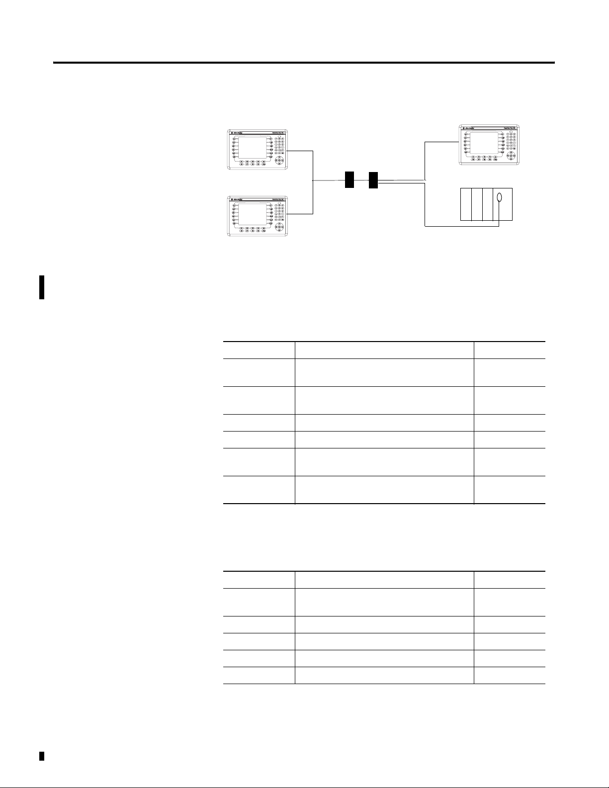
Modbus Master/Slave Networks
See Chapter 7 for cable information.
Direct Connection
PanelView Plus
(Modbus Serial or
Unsolicited Serial Driver)
RS-232/RS-485 Converter
(1)
1761-NET-AIC or Comparable Device
Master/Slave Network (Multiple Slave Terminals Connect to one Master Controller)
(3) PanelView Plus Slave Devices
Each uses Modbus Unsolicited Serial Driver
Controller (Master or Slave)
(1)
PanelView Plus
RS-232/RS-485
Converters
PanelView Plus
RS-232/RS-485
Converters
Modem Connection
PanelView Plus
PanelView Plus
RS-232/RS-485
Converters
(1) PanelView Plus Master Device
Uses the Modbus Serial Driver
Modbus Device
RS-232/RS-485
Converters
(2) PanelView Plus Slave Devices Modbus
Each uses the Modbus Unsolicited Serial Driver
PanelView Plus
Modbus Device
RS-232/RS-485
Converters
Master Controller
Master Controller
Modbus Device
Publication 2711P-UM002B-EN-P - March 2007
PanelView Plus
Modems

Modbus KEPServer Drivers 13
Modbus ASCII
Modbus/TCP
Modbus ASCII protocol is typically used to connect to other ASCII
devices that support the Modbus ASCII protocol. KEPServer support
includes:
• Modbus ASCII compatible devices
• Flow Computers using Daniels/Omni/Elliott register addressing
Modbus/TCP is a Modbus messaging protocol over Ethernet TCP/IP
and is intended for supervision and control of automation equipment.
The most common use of this protocol is for Ethernet attachment of
PLCs, I/O modules, and gateways to other simple field buses or I/O
networks.
The Modbus/TCP KEPServer driver supports Modbus and Mailbox
device models.
Modbus Device Model
The most common Modbus device model is where the driver connects
to physical devices (e.g. Modicon TSX Quantum, other Modbus Open
Ethernet compatible devices) and acts as a device on the network
with a device ID equivalent to the machine's IP address. The driver
accepts any unsolicited commands it receives and attempts to process
them as if it were another PLC.
MailBox
The Mailbox model determines the manner unsolicited requests are
handled. By defining a mailbox device, the driver does not act like a
PLC on the network (as described above). Instead, it acts as a storage
area for each and every mailbox device defined. When the driver
receives an unsolicited command, the driver detects the IP address the
message came from and places the data in the storage area allocated
for the device. If the message comes from a device with an IP address
that has not been defined as a mailbox device, the message is not
processed. Any client application that reads/writes to this type of
device, reads/writes to the storage area contained in the driver, not
the physical device.
Publication 2711P-UM002B-EN-P - March 2007
14 Modbus KEPServer Drivers
Refer to the MSTR instruction in your Modicon documentation for
details on sending unsolicited requests to the Modbus Ethernet driver.
PanelView Plus
PanelView Plus
Ethernet
Switch
Ethernet
Switch
PanelView Plus
Master Controller
Guidelines for Developing Modbus Applications
The section provides general guidelines for creating and running
Modbus applications on PanelView Plus/PanelView Plus CE terminals.
Create a Modbus Application
General Steps Description Reference
Step 1 Create a .pfe project file in KEPServer
Enterprise.
Step 2 Configure a KEPServer Modbus Driver. Add a
channel and device to the project file.
Step 3 Enter application tags. Chapter 3
Step 4 Set your .pfe file as the default project file. Chapter 3
Step 5 Test KEPServer communications to verify your
project file and tags.
Step 6 Create an OPC Data Server to make your tags
available in RSView Studio.
Chapter 3
Chapter 3
Chapter 4
Chapter 5
Compile, Download and Run a Modbus application
Publication 2711P-UM002B-EN-P - March 2007
General Steps Description Reference
Step 1 Create a firmware upgrade card that contains
the KEPWare driver and upgrade the terminal.
Step 2 Compile the RSView .mer application. Chapter 7
Step 3 Download the .mer runtime file to terminal. Chapter 7
Step 4 Connect the terminal to the Modbus network. Chapter 7
Step 5 Run the application. Chapter 7
Chapter 6

Chapter
Configuring KEPServer Drivers for Modbus
3
Objectives
Create a Project File
This chapter shows how to use KEPServer Enterprise software to
configure KEPServer drivers for Modbus protocols including Ethernet
TCP/IP, RTU Serial, Unsolicited Serial, and ASCII Serial. You will:
• create a project (.pfe) for the drivers
• set the project file as the default project
For each Modbus driver in your project file, you will:
• add a channel
• add a device (or controller)
• create tags
The first thing you need to do is create a project file.
1. Double-click the KEPServer Enterprise icon in the Systray to
open the default project window below.
15 Publication 2711P-UM002B-EN-P - March 2007

16 Configuring KEPServer Drivers for Modbus
2. Create a new KEPServer project (.pfe) file. From the menu,
select File>Save As and save the project as a .pfe file.
Select the Default Project File (.pfe)
The steps in this section ensure that the correct project file is used in
your RSView Studio application.
When RSView Studio creates a runtime application and the application
contains the KEPware OPC server, RSView Studio will merge the
KEPware project file (.pfe) into the runtime file (.mer). The project file
that RSView Studio uses is defined by the Default project field in the
General tab of the Tools>Options menu in KEPware Server
Enterprise.
TIP
1. From the Menu bar, select Tools>Options…
This may not be the current configuration running in
KEPware Server Enterprise. If you are testing the
application on a PC, make sure the project name in
the title bar of KEPware Server Enterprise matches
the Project default field.
Publication 2711P-UM002B-EN-P - March 2007
2. On the General tab, click the button next to the Default
project textbox.
3. Select the desired .pfe file and click the button.

Configuring KEPServer Drivers for Modbus 17
You should now see the following:
4. Click the button and OK to accept the new project as
the default.
Configure Drivers for Modbus Protocols
TIP
This section shows how to configure KEPServer drivers that will allow
a PanelView Plus/PanelView Plus CE terminal to communicate on a
Modbus network.
The KEPServer configuration is not archived with the
RSView Studio application backup (.apa) file. If you
need to reuse the project configuration file on
another computer, copy the .pfe file.
Add a Channel
The first step in communicating to any device using the KEPServer
software is to create a channel. A channel describes the protocol and
driver properties used for communication. While a single channel can
be used to communicate to multiple devices, separate channels must
be defined for each unique driver to be used. Only one project
configuration file can run at a time, but it may contain multiple
channels and devices.
Step 1 - Add a New Channel
Click on the New Channel icon or right-click anywhere in the left
pane. This will bring up the new channel wizard.
Step 2 - Enter a Channel Name
Enter a unique name for the channel.
Publication 2711P-UM002B-EN-P - March 2007

18 Configuring KEPServer Drivers for Modbus
Step 3 -Select a Device Driver
Select a driver from the drop down list. The table below lists the
correct driver for each Modbus protocol.
For this Protocol: Select this Driver:
Modbus/TCP Modbus Ethernet
Modbus RTU Serial (Master) Modbus Serial
Modbus Unsolicited Serial (Slave) Modbus Unsolicited Serial
Modbus ASCII Modbus ASCII Serial
Step 4 - Select a Network Adapter (for Modbus/TCP only)
The Network Adapter selection left allows you to select a specific NIC
card based on either the NIC name or its currently assigned IP
address. The list of available NICs will include either unique NIC cards
or NICs that have multiple IP addresses assigned to them.
Additionally, the selection will display any WAN connections you may
have active such as a dialup connection.
For PanelView Plus/PanelView Plus CE, select Default and click Next.
Step 5 - Enter Communication Settings (doesn’t apply to Modbus/TCP)
In the New Channel - Communications dialog, make sure the Modicon
controller configuration settings match those in slave controllers or
devices.
Parameter Selections Recommended
Data Bits 5, 6, 7, 8 8
Stop Bits 1, 2 1
Parity None, Even, Odd Even
Baud 300 to 256000 9600 or 19200
Publication 2711P-UM002B-EN-P - March 2007

Modbus RTU Serial
Modbus Unsolicited Serial
Configuring KEPServer Drivers for Modbus 19
Publication 2711P-UM002B-EN-P - March 2007

20 Configuring KEPServer Drivers for Modbus
Modbus ASCII
Step 6 - Set the Optimization Method for Data Requests
The New Channel - Write Optimization dialog sets the optimization
method for data requests. Select the best optimization for your
application and click Next.
For more information on KEPServer read and write optimization
options refer to the online Driver help.
Applies to all Modbus protocols
Publication 2711P-UM002B-EN-P - March 2007

Configuring KEPServer Drivers for Modbus 21
Step 7 -Select Socket Usage (Applies to Modbus/TCP only)
The New Channel - Socket Usage dialog controls how the Modbus
Ethernet driver will utilize Windows sockets when establishing a
connection to the target device. For a normal Modbus Ethernet
enabled device, the default Use Multiple Sockets for device
connection (checked) mode of operation is designed to give the best
performance from the driver.
Normally, the Modbus Ethernet driver will use a Windows socket for
each device on the network. When using a new socket connection for
each device, the Modbus Ethernet driver maintains that socket as an
active connection. Normally this provides a very high level of
performance since the driver does not need to reestablish a
connection each time it needs to read or write data to a given device.
For more information on using Sockets in a Modbus RTU bridge
application, refer to the online help.
Click Next.
Publication 2711P-UM002B-EN-P - March 2007

22 Configuring KEPServer Drivers for Modbus
Step 8 - View and Verify Channel Summary
The New Channel - Summary dialog provides a summary of the new
channel settings. Verify the settings below and click Finish.
Modbus/TCP
Modbus RTU Serial
Publication 2711P-UM002B-EN-P - March 2007

Modbus Unsolicited Serial
Modbus ASCII Serial
Configuring KEPServer Drivers for Modbus 23
TIP
The red X next to the channel name will disappear
when a destination device is added under this driver.
Step 9 - Save Project File
From the Menu bar, select File>Save or click the Save button.
Publication 2711P-UM002B-EN-P - March 2007

24 Configuring KEPServer Drivers for Modbus
Add A Device
Now that a new channel is defined, you need to add a new device to
the channel. In most cases, selecting the default settings will allow
you to quickly configure and connect to a device.
Step 1 - Add a Device
Add a device by clicking on the Click to add a device hypertext or the
New Device icon. This will bring up the new device wizard. Here
you’ll add the information pertinent to the controller that you are
going to communicate with.
Step 2 - Enter a Device Name
In the New Device - Name dialog, enter a device name that will help
you identify the device later and click Next. In most cases, the device
will be a logic controller.
Step 3 - Select a Device Model
If the device you are defining supports more than one model, select a
model that best describes the device.
For this Protocol: Most Common Model:
MODBIS/TCP Modbus
Modbus RTU Serial Modbus
Modbus Unsolicited Serial N/A
Modbus ASCII Modbus ASCII
Publication 2711P-UM002B-EN-P - March 2007

Configuring KEPServer Drivers for Modbus 25
Step 4 - Select a Device ID
The device you are defining may be multidropped as part of a
network of devices. To communicate with the device, it must be
assigned a unique ID.
In the New Device - ID dialog, enter a unique Device ID (decimal
address) to identify the controller on the network. Enter the Device ID
and click Next.
For this Protocol: Device ID Range Data Format
Modbus/TCP
ModbusModbus RTU Serial 0 - 255 Decimal
Modbus Unsolicited Serial 1 - 247 Decimal
Modbus ASCII 1 - 247 Decimal
(1)
For master/slave communications, add a fifth octet to the IP address. Refer to your KEPWare
documentation for more details on Modbus/TCP master/slave communications.
(1)
xxx.xxx.xxx.xxx IP Address
Step 5 - Enter Device Communication Parameters
(Doesn’t apply to Modbus Unsolicited Serial Protocol)
In the New Device - Communication Parameters dialog, accept the
default communication parameters by clicking Next.
Publication 2711P-UM002B-EN-P - March 2007

26 Configuring KEPServer Drivers for Modbus
Step 6 - Configure Tag Database Options
(Doesn’t apply to Unsolicited Serial or ASCII Protocols)
In the New Device - Database Creation dialog, click Next to accept
the default tag database configuration options.
The automatic OPC tag database generation features of the server
have been designed to make the setup of your OPC application a Plug
and Play operation. For communication drivers that support this
feature, you can configure them to automatically build a list of OPC
tags within the server that correspond to device specific data. The
automatically generated OPC tags can then be browsed from your
OPC client.
Publication 2711P-UM002B-EN-P - March 2007

Configuring KEPServer Drivers for Modbus 27
Step 7 - Enter Device Settings
In the New Device - Settings dialog, accept the default settings by
clicking Next
Modbus/TCP
Modbus RTU Serial
Publication 2711P-UM002B-EN-P - March 2007

28 Configuring KEPServer Drivers for Modbus
Modbus Unsolicited Serial and Modbus ASCII
Step 8 - Set the Block Size for Reading Data from Device
(Doesn’t apply to Unsolicited Serial Protocol)
The New Device - Block Sizes dialog sets the largest block size for
reading I/O (coils) and data tables (Registers). Click Next.
Modbus/TCP, Modbus RTU Serial, Modbus ASCII
Publication 2711P-UM002B-EN-P - March 2007
 Loading...