

Page 1
Installation Instructions
Applicable Terminals
Contents
Replacement Keyswitch Assembly
(Catalog No. 2711E-NKSW1)
Use this replacement keyswitch with PanelView Terminals 2711-KA1,
-KC1, -TA1, -TC1, -TA4, -TC4 and PanelView 1400e Terminals Series E
and earlier)
This document contains instructions for multiple terminals. Refer to
the section that applies to your terminal.
Section Page
Tools Required 1
Important 2
PanelView 1200 Terminals Series A through Series C 3
PanelView 1200 Terminals Series D and Series E 9
PanelView 1200 Series F through Series G, all PanelView 1200e
PanelView 1400e Series A through Series E
14
18
Tools Required
Troubleshooting- All Terminals
Tools Required:
• flat-blade screwdriver
• phillips screwdriver
• 7/8 inch. open-ended wrench
• needle nose pliers
21
1 40061-135-01(C)
Page 2
2 Replacement Keyswitch Assembly
Important
Replacement of the Keyswitch Assembly should be performed by a
qualified technician who has experience in the service and repair of
electronic equipment. In no event will Allen-Bradley LLC be
responsible for indirect or consequential damages resulting from the
replacement of this part.
Use an anti-static mat or wear a grounding wrist strap whenever you
work with any electronic components.
ATTENTION
Make sure that the PanelView terminal’s power cord
is disconnected, and that all cables have been
disconnected from the rear of the terminal.
!
ATTENTION
The electronic components in PanelView terminals
are extremely sensitive to static electricity and may
be permanently damaged by electrostatic discharges.
Follow proper handling procedures for electrostatic
devices.
!
Back Up Your Application File
If you have no disk copy of the application file (as it was created in
PanelBuilder) make one before opening the terminal. Upload the
application file to a computer running PanelBuilder 1400e and save
the file on disk.
40061-135-01(C)
Page 3
Replacement Keyswitch Assembly 3
PV1200 Series A through
Series C
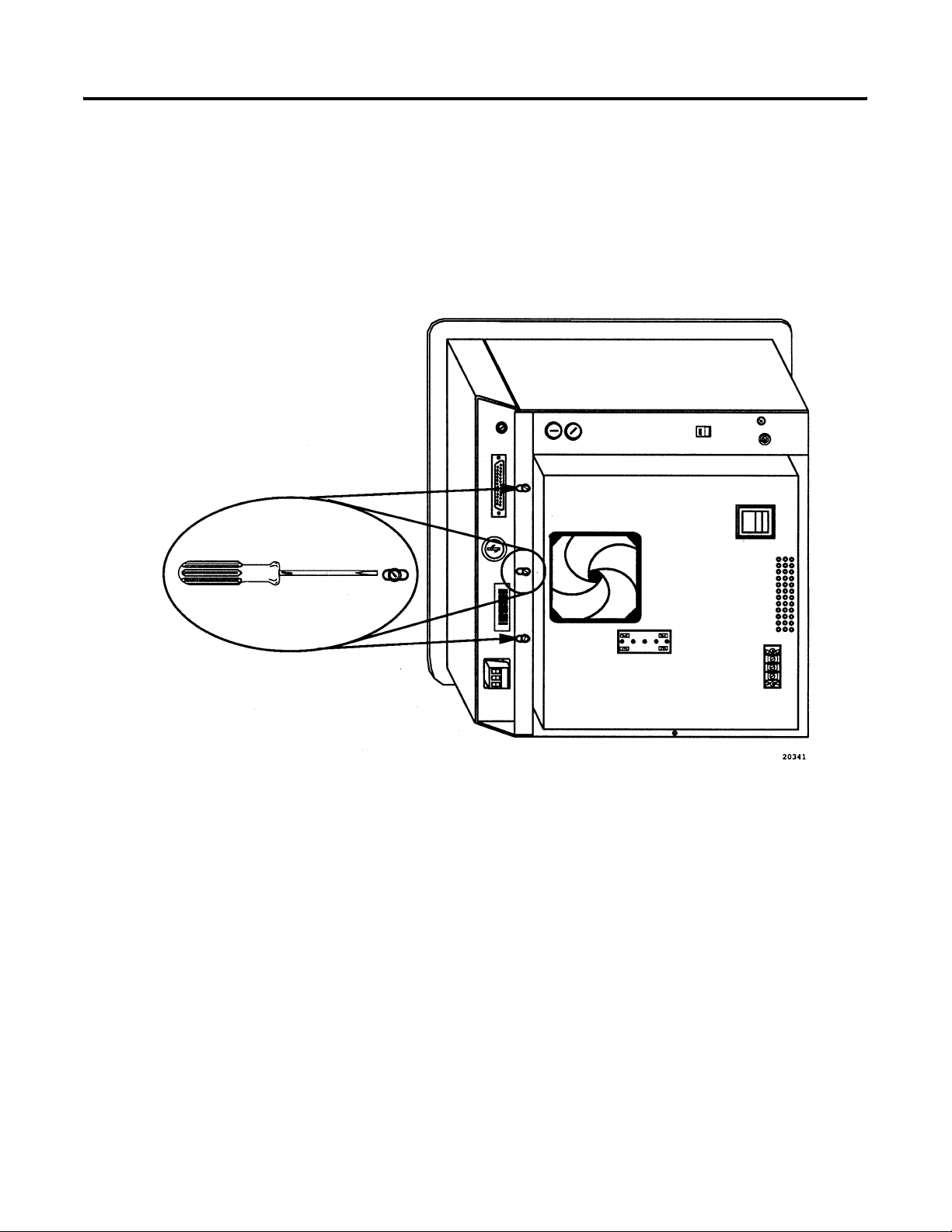
Open the Logic Board Drawer
1. Place the terminal on its side on top of a protective surface.
2. Remove the three screws which hold the logic board drawer
closed.
3. Swing the drawer open.
40061-135-01(C)
Page 4
4 Replacement Keyswitch Assembly
PV 1200 Series A through
Series C (Continued)
J1
J2
J3
J4
J8
J7
J6
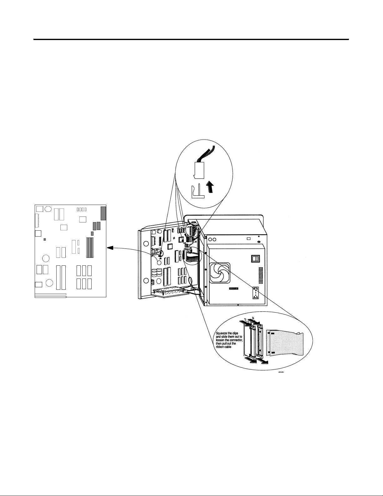
Disconnect the Logic Board
Remove the connections from points J1, J2, J3, J4, J6, J7 and J8 on the
logic board.
Note: Cables J2 and J4 are only present on color terminals; J3 is
only present on monochrome terminals.
40061-135-01(C)
Page 5
Replacement Keyswitch Assembly 5
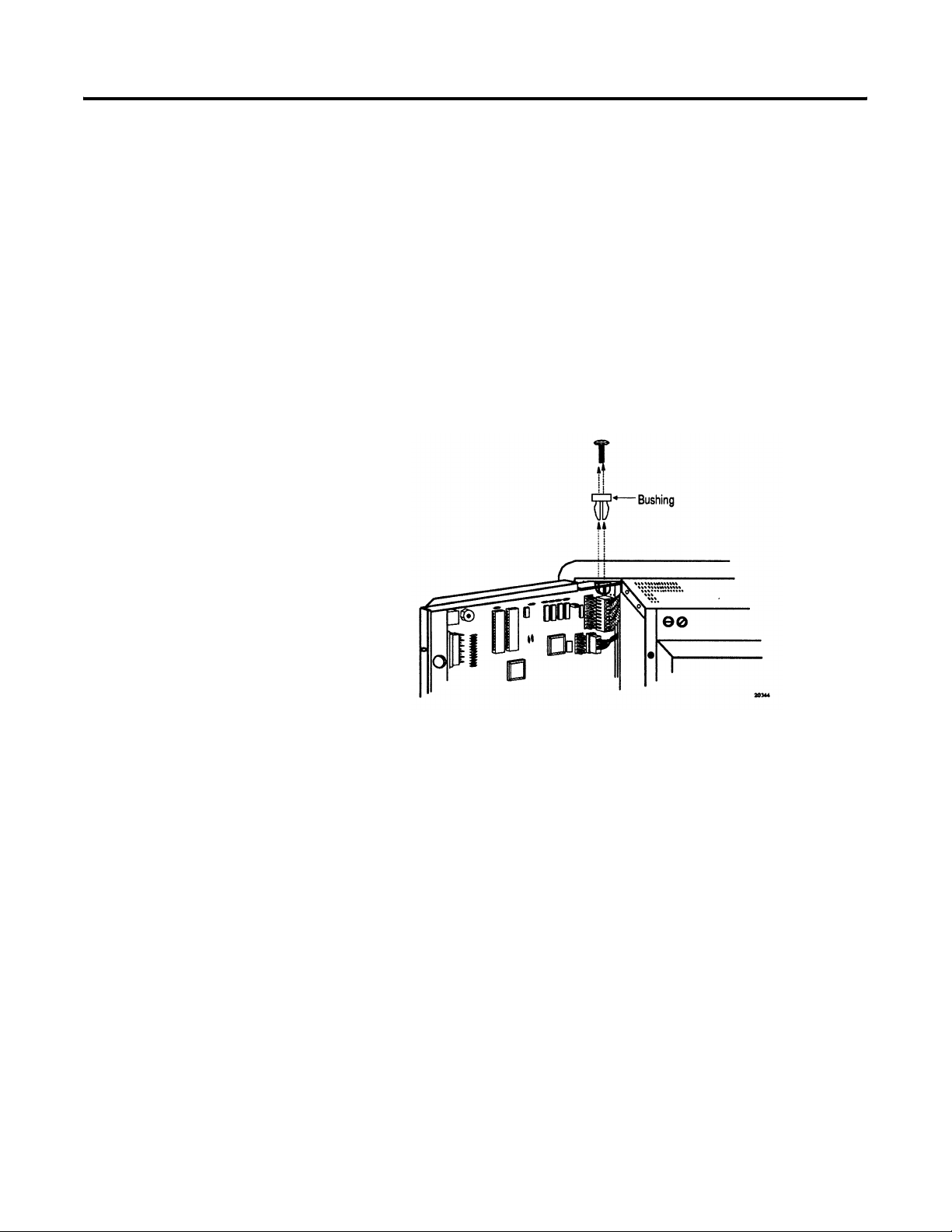
Remove the Logic Board Drawer
The drawer hinges are white nylon bushings held in place by a
phillips screw.
1. Remove the screw from the top hinge (the one opposite the side
with the ground wire). Using needle nose pliers, pinch the
prongs on the bushing and push the bushing upwards, out of
the metal tab.
2. Swing the drawer outwards, and the other bushing will detach,
allowing the drawer to be removed. The ground wire can
remain attached.
40061-135-01(C)
Page 6
6 Replacement Keyswitch Assembly
PV 1200 Series A through
Series C (Continued)
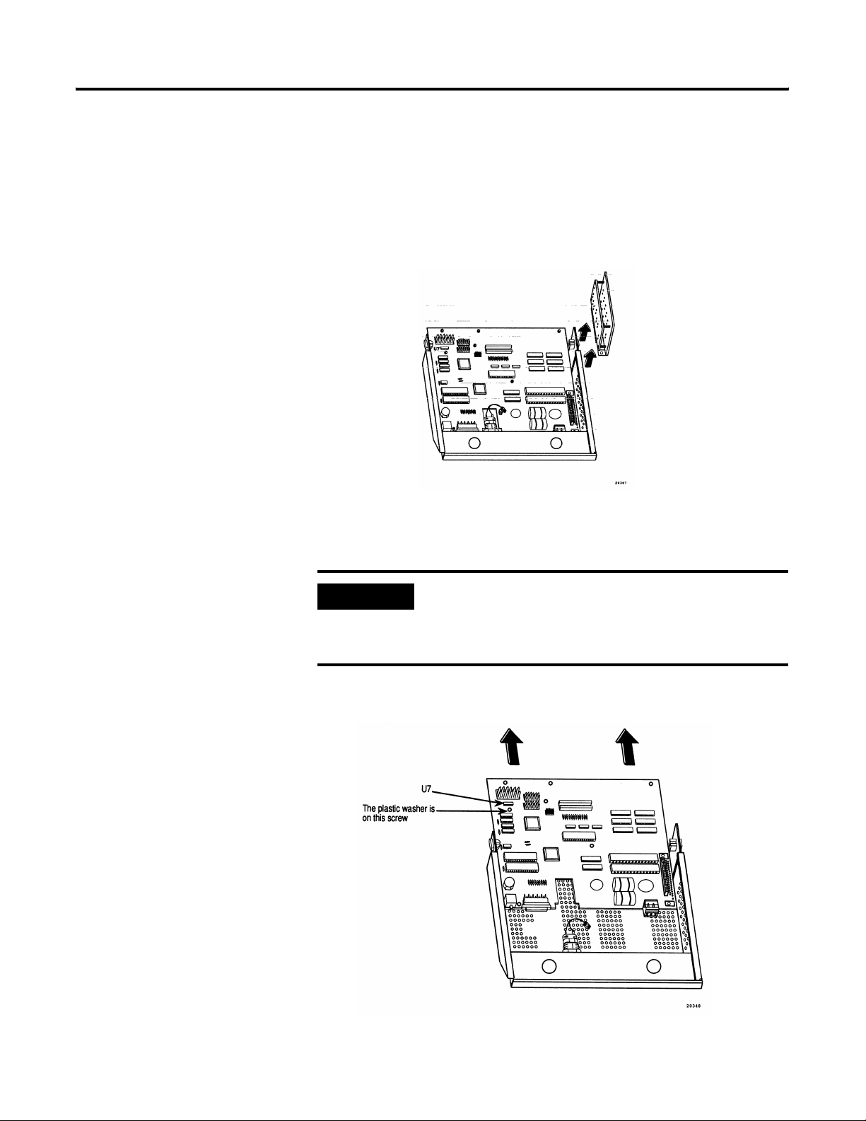
Remove the Node Adapter and the Logic Board
The node adapter board assembly is attached to the logic board by
two screws and an edge-connector plug.
1. Remove the screws and slide the assembly straight up to unplug.
2. Remove the eight phillips screws holding the logic board to the
drawer and slide out the logic board.
IMPORTANT
When removing the logic board mounting screws,
note that the screw located below U7 has a plastic
washer. This washer must be installed in the same
position during reassembly.
40061-135-01(C)
Page 7
Replacement Keyswitch Assembly 7
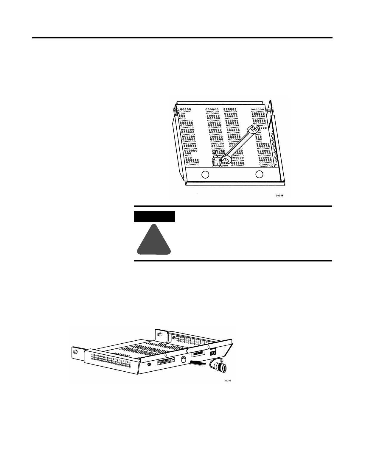
Remove the Keyswitch
Using a 7/8 inch wrench, remove the nut securing the keyswitch.
Remove the keyswitch.
ATTENTION
Do not hold the keyswitch by the plastic section of
the body. Twisting the plastic section can damage
the keyswitch.
!
Insert the New Keyswitch
1. Slide in the replacement keyswitch and secure it to the drawer
with the nut.
2. Orient the keyswitch so that the key’s teeth face upwards. Align
the two flat surfaces of the switch with the two flat edges of the
opening in the drawer.
40061-135-01(C)
Page 8
8 Replacement Keyswitch Assembly
PV 1200 Series A through
Series C (Continued)
Reassemble the Terminal
1. Slide in the logic board. Attach the eight mounting screws
(remember to replace the plastic washer removed earlier).
2. Plug in the Node Adapter assembly, being careful to align the
pins in the edge connector, and then secure with two screws.
3. Reattach the bushing and put the drawer back into the terminal.
4. Reconnect the logic board:
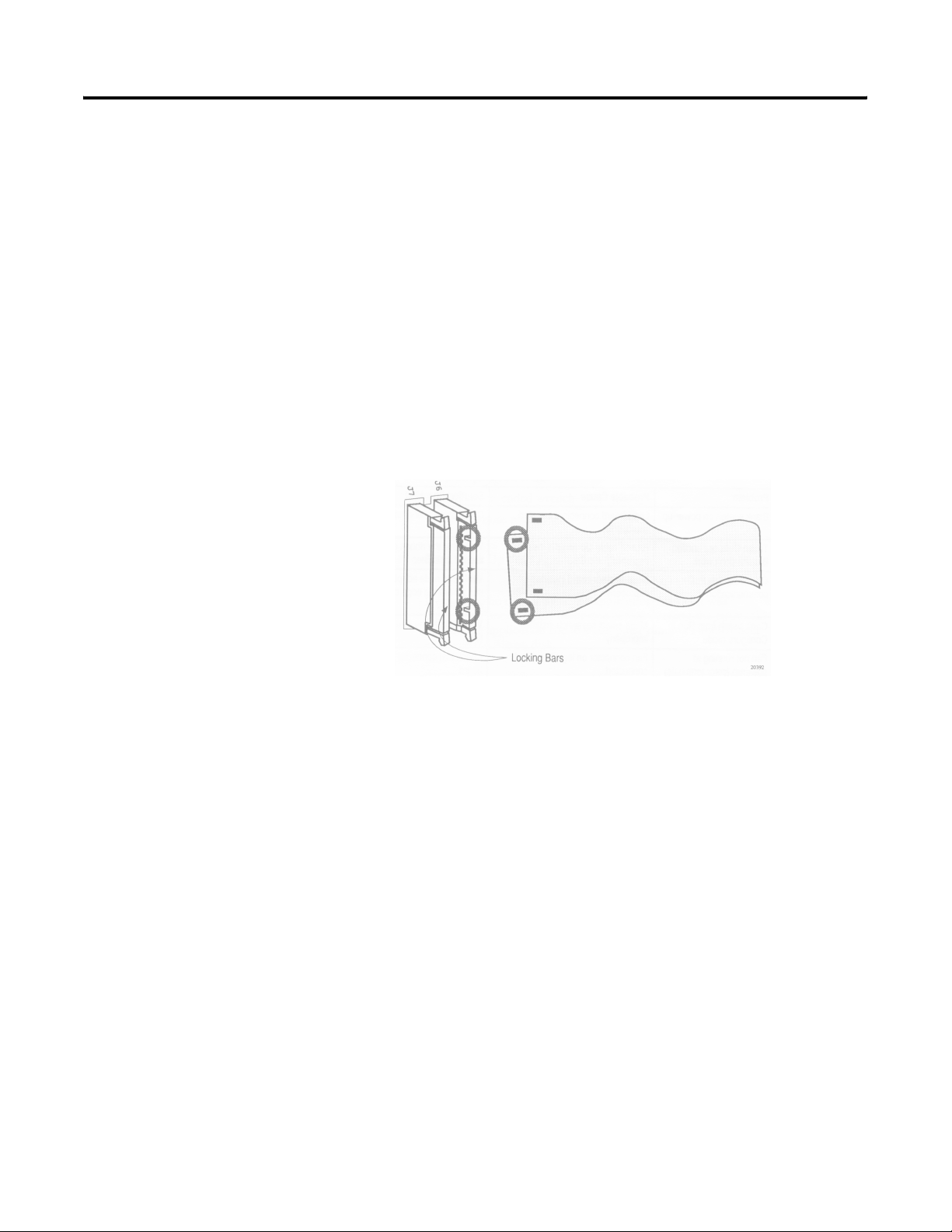
5. Reattach the ribbon cables to the logic board. With the locking
bars up, hook each cable onto the tabs in the connector as
shown below. Push the connector and locking bar in to latch it
closed.
Close the Terminal
Test the Terminal
40061-135-01(C)
Make sure that there are no washers, screws, or other metal objects
left on or under the logic board. Close the logic board drawer and
secure with three screws.
1. Apply power to the terminal. On color terminals, listen to make
sure the fan is operating.
2. Set the mode-select keyswitch on the rear of the terminal to
CONFIGURE. The Configuration Mode menu should appear.
Switch to RUN; the terminal should enter Run Mode.
3. Switch to Configuration Mode and verify that all Unit Tests in the
Configuration Mode Menu are run successfully (refer to terminal
user manual).
Note: If the optional user PROMs are not installed, the Memory
Checksum test will indicate a failure at memory location 5000:0000.
this is normal.
Page 9

Replacement Keyswitch Assembly 9
PV1200 Series D
and Series E
Open the Logic Board Drawer
1. Place the terminal on its side on top of a protective surface.
2. Remove the screws which hold the logic board drawer closed.
3. Swing the drawer open.
Color Back Panel
Remove these
screws to access
the logic board.
Monochrome Back Panel
40061-135-01(C)
Page 10

10 Replacement Keyswitch Assembly
PV 1200 Series D and
Series E (Continued)
J3
Disconnect the Logic Board
Remove the connections from points J3, J4, J5, J6, J7, J8 and J9 on the
logic board.
J9
J8
J7
J5
J4
J6
40061-135-01(C)
Squeeze the clips and
slide them out to loosen
the connector, then pull
out the ribbon cable.
Page 11

Replacement Keyswitch Assembly 11
Remove the Logic Board Drawer
The drawer hinges are white nylon bushings held in place by a
phillips screw.
1. Remove the screw from the top hinge (the one opposite the side
with the ground wire). Using needle nose pliers, pinch the
prongs on the bushing and push the bushing upwards, out of
the metal tab.
2. Swing the drawer outwards, and the other bushing will detach,
allowing the drawer to be removed. The ground wire can
remain attached.
40061-135-01(C)
Page 12

12 Replacement Keyswitch Assembly
PV 1200 Series D and
Series E (Continued)
Remove the Logic Board
1. Remove the ten phillips screws holding the logic board to the
drawer and slide out the logic board.
IMPORTANT
When removing the logic board mounting screws,
note that the screw located below U7 has a plastic
washer. This washer must be installed in the same
position during reassembly.
Remove the Keyswitch
Using a 7/8 inch wrench, remove the nut securing the keyswitch.
Remove the keyswitch.
ATTENTION
Do not hold the keyswitch by the plastic section of
the body. Twisting the plastic section can damage
the keyswitch.
!
Insert the New Keyswitch
1. Slide in the replacement keyswitch and secure it to the drawer
with the nut.
2. Orient the keyswitch so that the key’s teeth face upwards. Align
the two flat surfaces of the switch with the two flat edges of the
opening in the drawer.
40061-135-01(C)
Page 13

Replacement Keyswitch Assembly 13
Reassemble the Terminal
1. Position the logic board in the logic board drawer and secure
with ten screws.
2. Reattach the bushing and put the drawer back into the terminal.
3. Reconnect the logic board ribbon cables and wire connectors:
Reattach the ribbon cables (J6 and J4) to the logic board. With
the locking bars up, hook each cable onto the tabs in the
connector as shown below. Push the connector and locking bar
in to latch it closed.
Close the Terminal
Test the Terminal
Make sure that there are no washers, screws, or other metal objects
left on or under the logic board. Close the logic board drawer and
secure with two screws.
1. Apply power to the terminal. On color terminals, listen to make
sure the fan is operating.
2. Set the mode-select keyswitch on the rear of the terminal to
CONFIGURE. The Configuration Mode menu should appear.
Switch to RUN; the terminal should enter Run Mode.
3. Switch to Configuration Mode and verify that all Unit Tests in the
Configuration Mode Menu are run successfully (refer to terminal
user manual).
Note: If the optional user PROMs are not installed, the Memory
Checksum test will indicate a failure at memory location
5000:0000. This is normal.
40061-135-01(C)
Page 14

14 Replacement Keyswitch Assembly
PV1200 Terminals Series F
through Series G,
All PanelView 1200e
Open the Logic Board Drawer
1. Place the terminal on its side on top of a protective surface.
2. Remove the two screws which hold the logic board drawer
closed.
3. Swing the drawer open.
PanelView 1200 Terminals
Keyswitch
Remove these
screws to access
the logic board.
J6
P2
J1
P3
Disconnect the Logic Board
Remove the connections from points J1, P1, P2, P3 and J6 on the logic
board.
P1
Squeeze the clips and
slide them out to loosen
the connector, then pull
out the ribbon cable.
40061-135-01(C)
Page 15

Replacement Keyswitch Assembly 15
Remove the Logic Board Drawer
The drawer hinges are white nylon bushings held in place by a
phillips screw.
1. Remove the screw from the top hinge (the one opposite the side
with the ground wire). Using needle nose pliers, pinch the
prongs on the bushing and push the bushing upwards, out of
the metal tab.
2. Swing the drawer outwards, and the other bushing will detach,
allowing the drawer to be removed. The ground wire can
remain attached.
Remove the Logic Board
1. Remove the ten phillips screws holding the logic board to the
drawer and slide out the logic board.
IMPORTANT
PanelView 1200 - When removing the logic board
mounting screws, note that the screw located below
U7 has a plastic washer. This washer must be
installed in the same position during reassembly.
40061-135-01(C)
Page 16

16 Replacement Keyswitch Assembly
PV1200 Terminals Series F
through Series G,
All PanelView 1200e
(Continued)
Remove the Keyswitch
Using a 7/8 inch wrench, remove the nut securing the keyswitch.
Remove the keyswitch.
ATTENTION
Do not hold the keyswitch by the plastic section of
the body. Twisting the plastic section can damage
the keyswitch.
!
Insert the New Keyswitch
1. Slide in the replacement keyswitch and secure it to the drawer
with the nut.
2. Orient the keyswitch so that the key’s teeth face upwards. Align
the two flat surfaces of the switch with the two flat edges of the
opening in the drawer.
Reassemble the Terminal
1. Position the logic board in the logic board drawer and secure
with ten screws.
2. Reattach the bushing and put the drawer back into the terminal.
3. Reconnect the logic board ribbon cables and wire connectors:
Reattach the ribbon cables (J6 and J4) to the logic board. With
the locking bars up, hook each cable onto the tabs in the
40061-135-01(C)
Page 17

Replacement Keyswitch Assembly 17
connector as shown below. Push the connector and locking bar
in to latch it closed.
Close the Terminal
Test the Terminal
Make sure that there are no washers, screws, or other metal objects
left on or under the logic board. Close the logic board drawer and
secure with two screws.
1. Apply power to the terminal. On color terminals, listen to make
sure the fan is operating.
2. Set the mode-select keyswitch on the rear of the terminal to
CONFIGURE. The Configuration Mode menu should appear.
Switch to RUN; the terminal should enter Run Mode.
3. Switch to Configuration Mode and verify that all Unit Tests in the
Configuration Mode Menu are run successfully (refer to terminal
user manual).
Note: If the optional user PROMs are not installed, the Memory
Checksum test will indicate a failure at memory location 5000:0000.
this is normal.
40061-135-01(C)
Page 18

18 Replacement Keyswitch Assembly
PanelView 1400e Series A
through Series E
Open the Logic Board Drawer
1. Place the terminal on its side on top of a protective surface.
2. Remove the two screws which hold the logic board drawer
closed.
3. Swing the drawer open.
PanelView 1400e Terminals
Keyswitch
Remove these
screws to access
the logic board.
Disconnect the Logic Board
Remove the connections from points J1, J5, J6 and P3 on the logic
board.
J1
J6
J5
P3
40061-135-01(C)
Page 19

Replacement Keyswitch Assembly 19
Remove the Logic Board Drawer
Carefully pull on one side of the drawer (side opposite green ground
wire) to dislodge the hole in the drawer from the rounded protrusion
on one side of the chassis.
Copper Finger Strip
Ground Wire
Dislodge Drawer
from Chassis
Note: Be careful that you don’t damage the copper finger strip or
ground wire.
Pull on this side
Remove the Logic Board
Remove the seven phillips screws holding the logic board to the
drawer and slide out the logic board.
Remove the Keyswitch
Using a 7/8 inch wrench, remove the nut securing the keyswitch.
Remove the keyswitch.
ATTENTION
Do not hold the keyswitch by the plastic section of
the body. Twisting the plastic section can damage
the keyswitch.
!
40061-135-01(C)
Page 20

20 Replacement Keyswitch Assembly
PanelView 1400e Series A
through Series E
(Continued)
Insert the New Keyswitch
1. Slide in the replacement keyswitch and secure it to the drawer
with the nut.
2. Orient the keyswitch so that the key’s teeth face upwards. Align
the two flat surfaces of the switch with the two flat edges of the
opening in the drawer.
Reassemble the Terminal
1. Position the logic board in the logic board drawer and secure
with seven screws.
2. Reattach the bushing and put the drawer back into the terminal.
3. Reconnect the logic board ribbon cables and wire connectors:
Close the Terminal
Make sure that there are no washers, screws, or other metal objects
left on or under the logic board. Close the logic board drawer and
secure with two screws.
Test the Terminal
1. Apply power to the terminal. On color terminals, listen to make
sure the fan is operating.
2. Set the mode-select keyswitch on the rear of the terminal to
CONFIGURE. The Configuration Mode menu should appear.
Switch to RUN; the terminal should enter Run Mode.
3. Switch to Configuration Mode and verify that all Unit Tests in the
Configuration Mode Menu are run successfully (refer to terminal
user manual).
40061-135-01(C)
Page 21

Replacement Keyswitch Assembly 21
Troubleshooting
(All Terminals)
Problem Probable Cause(s) Corrective Action
Blank screen on power-up. Logic board is improperly
installed.
Touch cells or Function buttons
don’t work.
Can’t establish PLC
communication.
Can’t switch from run to Configure
mode.
Fan nor running at powerup (color
terminals).
Ribbon cables installed
improperly.
Node adapter board improperly
installed (PV1200 Series A - C).
Mode-select switch is
improperly installed.
Fan connector on logic board is
not connected.
Check that all connectors are properly connected
and oriented.
Check that cables are properly attached.
Verify that the node adapter is securely plugged in.
Make sure that the pins in the edge connector are
properly aligned.
Verify that the new keyswitch is properly attached.
Check that connector is connected to the logic
board.
40061-135-01(C)
Page 22

Page 23

Page 24

22 PN 40061-135-01(C)
© 2000 Rockwell International Corporation. Printed in the U.S.A.
 Loading...