

Page 1

Installation Data Sheet
Replacing the PanelView
1400e Keypad Faceplate
(Catalog Number 2711E-NK5)
(For PanelView Terminals 2711E-K14C6,
2711E-K14C7, 2711E-K14C15)
Description
Package Contents
Before You Begin
This document provides instructions for replacing the
PanelView 1400e terminal’s keypad faceplate.
The keypad faceplate should be replaced by a qualified technician
who has experience in the service and repair of solid state
equipment. In no event will Allen-Bradley Company be responsible
or liable for indirect or consequential damages resulting from the
replacement of this part.
This kit includes:
• keypad faceplate with controller
• 6 keypad faceplate mounting screws with washers
• 18 terminal mounting nuts and washers
Tools Required:
No. 2 Phillips screwdriver with a long shaft
•
• Torque wrench capable of 27 inch-pounds torque
• Torque wrench capable of 15 inch-pounds torque
• Removeable thread locker (Loctite 242, Part Number 24221)
• Torx T-15 driver
• Wood block to elevate terminal keypad faceplate
Save Your Terminal Configuration and Application File
Before opening the terminal, write down the terminal’s settings
(serial port, audio response, and screen saver configuration). If you
have no disk copy of the application file (as it was created in
PanelBuilder), upload the application file to a computer running
PanelBuilder and save the file on disk.
Page 2
Replacing the PanelView 1400e Keypad Faceplate2
Precautions
ATTENTION: To replace the keypad faceplate, you
will need to put the unit face down gently onto a clean,
!
!
!
You should use an anti-static mat or wear a grounding wrist/foot
strap whenever you work with any electronic components sensitive
to electrostatic discharges.
soft protective surface. Be careful not to jar the unit.
Permanent CRT damage can result.
ATTENTION: Ensure that the PanelView terminal’s
power cord is disconnected and that all cables have
been disconnected from the rear of the terminal.
ATTENTION: The electronic components in
PanelView terminals are extremely sensitive to static
electricity and can be permanently damaged by
electrostatic discharges. Follow the proper handling
procedures for electrostatic-sensitive devices.
Step 1. Disconnecting and Dismounting the Terminal
If you are not using any anti-static mat or wrist/foot strap, follow
these precautions:
• assume that your body is always carrying a static charge
• touch any grounded metal surface to discharge yourself. Do this
frequently
• wear cotton clothes, not wool or synthetic fabrics
• do not move too much or scuff your feet when walking on carpets
• be extra careful in low-humidity environments
T o disconnect and dismount the terminal:
1. Disconnect power from the terminal at the source.
2. Disconnect all cabling from the back of the terminal.
3. Dismount the terminal from its panel or rack.
Page 3
Replacing the PanelView 1400e Keypad Faceplate 3
Step 2. Removing the Keypad Faceplate
T o remove the keypad faceplate:
1. Place the terminal face down on a protective surface.
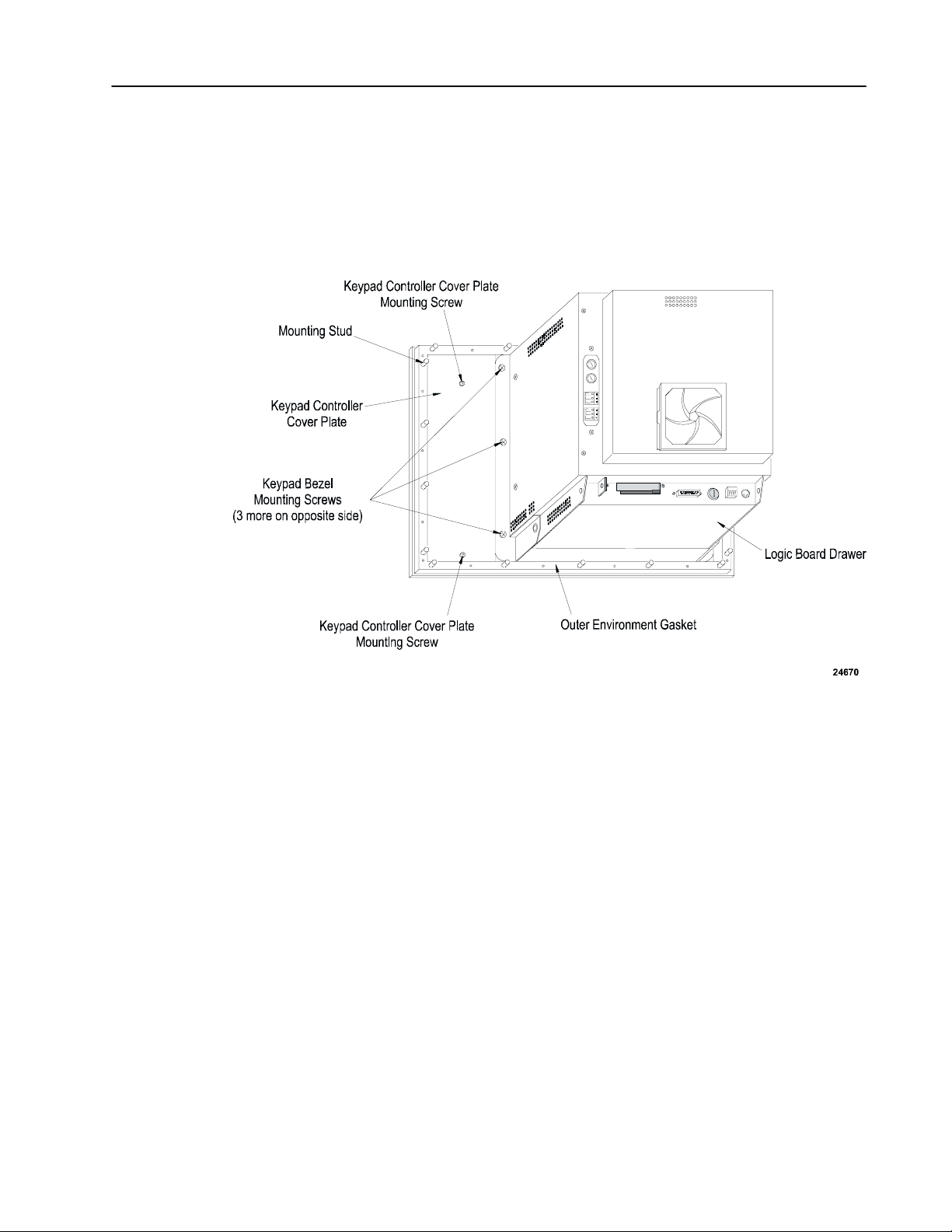
2. Use a Torx T-15 driver to remove the two small black screws
holding the cover plate on the left side of the keypad faceplate.
Save the screws and the plate.
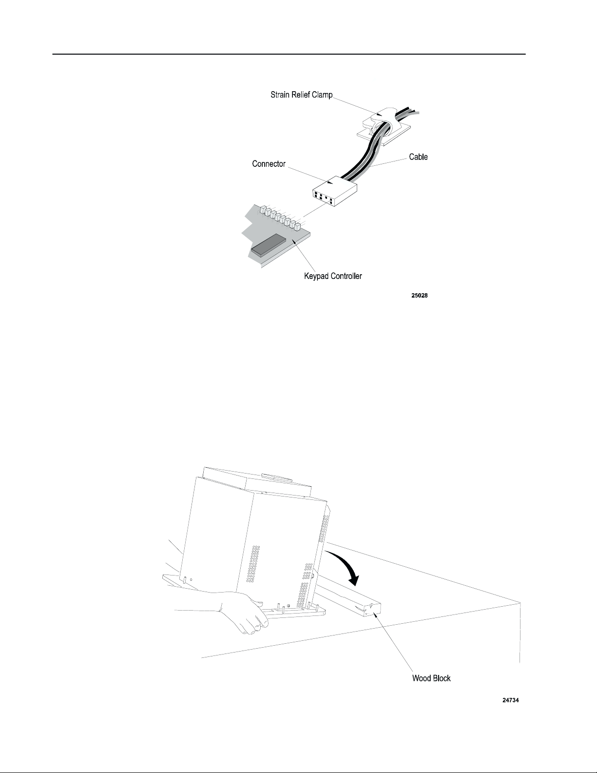
3. The cable between the terminal and the keypad controller on the
faceplate is clipped to the terminal by a strain-relief clamp.
Release this by pressing down on the lower tab.
Page 4
Replacing the PanelView 1400e Keypad Faceplate4
4. Disconnect the cable from the controller board on the keypad
faceplate. Note the position and orientation of the cable so that
you can reconnect it properly.
5. The keypad faceplate is attached to the terminal by six Phillips
screws, three on each side. Use the No. 2 Phillips screwdriver to
remove them. The location of the screws is shown above.
6. When you have removed all the screws, tilt the unit up into
operating position, holding the faceplate in place. Gently set the
terminal on its bottom.
Page 5

Replacing the PanelView 1400e Keypad Faceplate 5
7. Gently pull the keypad faceplate away from the unit at the top.
Step 3. Preparing the New Keypad Faceplate
T o prepare the new keypad faceplate:
Important: Prepare the new keypad faceplate in a dust-free
environment.
1. Lay the keypad faceplate face down on a clean, soft, protective
surface.
2. Use glass cleaner to remove all fingerprints, streaks, and lint from
the back of the keypad faceplate and the front surface of the CRT
screen.
Important: Don’t spray glass cleaner into the open terminal
to clean the CRT surface. Instead, spray the
glass cleaner onto a clean cloth, and wipe the
CRT surface.
3. If you had customized your legend key inserts, you may want to
remove the customized legend key inserts from your old keypad
faceplate and insert them into your replacement keypad faceplate.
Page 6

Replacing the PanelView 1400e Keypad Faceplate6
Step 4. Attaching the New Keypad Faceplate
Pull gently on the blue tabs to remove the legend key inserts from
the old keypad faceplate and the new legend key inserts from the
replacement keypad faceplate. Carefully insert the customized
legend inserts from your old faceplate into your replacement
faceplate.
4. Verify that the keypad faceplate is clean. If there are any new
streaks or spots, remove them with glass cleaner and lint-free
wipes.
T o attach the new keypad faceplate:
1. Place the new keypad faceplate flat on the table in front of the
terminal.
2. Apply Loktite on the bottom four or five threads of each of the
six screws. Be sparing with the Loktite.
3. Lift the faceplate into position onto the terminal. Fit the locating
pins on the faceplate into the openings on the terminal.
Important: Be careful when aligning the pins with the holes.
If they aren’t properly aligned, the pins can
scratch the terminal.
Page 7

Replacing the PanelView 1400e Keypad Faceplate 7
4. Holding the faceplate in position with one hand, start the middle
screw on one side of the faceplate. Tighten it “finger-tight”, that
is, as tight as you can by hand.
Important: Start these screws very carefully, either by hand
or with a screwdriver; it is very important not to
strip the threads in the screw holes. If you
should strip or cross-thread a hole, it may be
necessary to return the unit for service.
5. Start the middle screw on the other side of the faceplate and
“finger tighten”.
6. Place the terminal on its face.
Page 8

Replacing the PanelView 1400e Keypad Faceplate8
7. Start the remaining screws around the outside of the terminal.
8. Use the torque wrench to tighten them to a torque of
27 inch-pounds.
9. Connect the cable to P1 on the controller board of the new
keypad faceplate. Be careful to replace the connector with the
same orientation as when you disconnected it. The cable is keyed
to match the connector.
10. Snap the cable into the strain relief clamp, and lock it by pressing
the upper tab.
11. Use the T15 bit to reattach the keypad controller cover plate at
the back of the keypad. Tighten these screws to a torque of
15 inch-pounds.
Page 9

Replacing the PanelView 1400e Keypad Faceplate 9
Step 5. Remounting and Reconnecting
T o remount and reconnect the terminal:
1. Remount the terminal in its rack or panel. Secure the 18 nuts and
washers, provided in the kit, to terminal mounting studs. Terminal
mounting nut torque should not exceed 10 inch-pounds.
2. Ensure the outer environmental gasket is properly sealed, and is
not squeezed or pinched.
Important: An outer environmental gasket of heavy foam
rubber is already installed on your replacement
keypad faceplate. The NEMA-rated
environmental protection of your terminal
depends on the seal created when this gasket is
properly seated. Be careful not to damage this
gasket.
3. Remove the protective cover from the front of the faceplate.
4. Reconnect the cabling to the back of the terminal.
5. Reapply power to the terminal.
If the major fault message, “keypad not responding”, appears:
• check that the keypad cable is connected properly to the logic
board connector J5
• check that the other end of the keypad cable is properly connected
to the keypad controller board at connector P1
Step 6. Testing the Terminal
T o test the terminal:
1. Set the terminal mode to Configure mode. The Mode Select
Keyswitch is located at the back of the terminal.
2. In the Terminal Configuration screen main menu, select the
Terminal Diagnostics button.
3. In the Terminal Diagnostics screen, select the System Tests tab
and then select the Function Keys (F4) button.
Page 10

Replacing the PanelView 1400e Keypad Faceplate10
Test each key by pressing it. If the key is working, the
corresponding key will appear to be pressed on the screen. F21 is
the exit button. If you find any keys difficult to activate or
inoperable, recheck the keypad cable connections for J5 on the
logic board and P1 on the keypad controller board. If the problem
persists, return the keypad faceplate kit for replacement.
Page 11

PanelView is a trademark of Allen Bradley, Inc.
All other brand and product names are trademarks or registered
trademarks of their respective companies and are hereby acknowledged.
Rockwell Automation helps its customers receive a superior return on their investment by bringing
together leading brands in industrial automation, creating a broad spectrum of easy-to-integrate
products. These are supported by local technical resources available worldwide, a global network
of system solutions providers, and the advanced technology resources of Rockwell.
Worldwide representation.
Argentina • Australia • Austria • Bahrain • Belgium • Bolivia • Brazil • Bulgaria • Canada • Chile • China, People’s Republic of • Colombia • Costa Rica • Croatia • Cyprus
Czech Republic • Denmark • Dominican Republic • Ecuador • Egypt • El Salvador • Finland • France • Germany • Ghana • Greece • Guatemala • Honduras • Hong Kong
Hungary • Iceland • India • Indonesia • Iran • Ireland • Israel • Italy • Jamaica • Japan • Jordan • Korea • Kuwait • Lebanon • Macau • Malaysia • Malta • Mexico •Morocco
The Netherlands • New Zealand • Nigeria • Norway • Oman • Pakistan • Panama • Peru • Philippines • Poland • Portugal • Puerto Rico • Qatar • Romania • Russia • Saudi
Arabia • Singapore • Slovakia • Slovenia • South Africa, Republic of • Spain • Sweden •Switzerland • Taiwan • Thailand • T rinidad • Tunisia • T urkey • United Arab Emirates
United Kingdom • United States • Uruguay • Venezuela
Rockwell Automation Headquarters, 1201 South Second Street, Milwaukee, WI 53204-2496 USA, T el: (1) 414 382-2000 Fax: (1) 414 382-4444
Rockwell Automation European Headquarters, Avenue Hermann Debroux, 46, 1160 Brussels, Belgium, Tel: (32) 2 663 06 00, Fax: (32) 2 663 06 40
Rockwell Automation Asia Pacific Headquarters, 27/F Citicorp Centre, 18 Whitfield Road, Causeway Bay, Hong Kong, Tel: (852) 2887 4788, Fax: (852) 2508 1846
World Wide Web: http://www.ab.com
May 1998 41061–060–01(A)
May 1998
Copyright 1998 Allen-Bradley Company, Inc. Printed in Canada
 Loading...