

Page 1
Allen-Bradley
PanelView
1200/1400e
Transfer Utility
(Cat. No. 2711E–ND7)
User
Manual
Page 2

Important User Information
Because of the variety of uses for the products described in this
publication, those responsible for the application and use of this
control equipment must satisfy themselves that all necessary steps
have been taken to assure that each application and use meets all
performance and safety requirements, including any applicable laws,
regulations, codes and standards.
The illustrations, charts, sample programs and layout examples
shown in this guide are intended solely for purposes of example.
Since there are many variables and requirements associated with any
particular installation, Allen-Bradley does not assume responsibility
or liability (to include intellectual property liability) for actual use
based upon the examples shown in this publication.
Allen-Bradley publication SGI-1.1, Safety Guidelines for the
Application, Installation, and Maintenance of Solid-State Control
(available from your local Allen-Bradley office), describes some
important differences between solid-state equipment and
electromechanical devices that should be taken into consideration
when applying products such as those described in this publication.
Reproduction of the contents of this copyrighted publication, in
whole or in part, without written permission of Allen-Bradley
Company, Inc., is prohibited.
Throughout this manual we use notes to make you aware of safety
considerations:
ATTENTION: Identifies information about practices
or circumstances that can lead to personal injury or
!
death, property damage or economic loss.
Attention statements help you to:
• identify a hazard
• avoid the hazard
• recognize the consequences
Important: Identifies information that is critical for successful
application and understanding of the product.
PanelBuilder, PanelView, Data Highway Plus, DH+, SLC, and SLC 500 are trademarks, and PLC, PLC-2, and PLC-3 are
registered trademarks of Allen-Bradley, Inc.
IBM, PC, AT, XT, PS/2, and PC DOS are registered trademarks of International Business Corporation.
Microsoft Windows and Windows NT are trademarks, and Microsoft, MS, and MS-DOS are registered trademarks of
Microsoft Corporation.
Ethernet is a registered trademark of Digital Equipment Corporation, Intel, and Xerox Corporation.
RSLinx, WINtelligent LINX, and INTERCHANGE are trademarks of Rockwell Software Inc.
All other brand and product names are trademarks or registered trademarks of their respective companies and are hereby
acknowledged.
Page 3

Preface
Before You Begin P–1. . . . . . . . . . . . . . . . . . . . . . . . . . . . . . . . . . . . .
Purpose of This Manual P–1. . . . . . . . . . . . . . . . . . . . . . . . . . . . . . . .
Contents of This Manual P–1. . . . . . . . . . . . . . . . . . . . . . . . . . . . . .
Related Publications P–2. . . . . . . . . . . . . . . . . . . . . . . . . . . . . . . .
Technical Support Services P–3. . . . . . . . . . . . . . . . . . . . . . . . . . . . . .
Allen-Bradley Support P–4. . . . . . . . . . . . . . . . . . . . . . . . . . . . . . . . .
Local Product Support P–4. . . . . . . . . . . . . . . . . . . . . . . . . . . . . . .
Conventions Used in This Manual P–4. . . . . . . . . . . . . . . . . . . . . . . . .
Transfer Utility Operating System Support P–4. . . . . . . . . . . . . . . . . . .
Introducing the PanelView 1200/1400e Transfer Utility
Working with the PanelView 1200/1400e Transfer Utility
Chapter 1
About the PanelView 1200/1400e T ransfer Utility 1–1. . . . . . . . . . . . . .
Types of Applications 1–2. . . . . . . . . . . . . . . . . . . . . . . . . . . . . . . . . .
Types of Transfers 1–3. . . . . . . . . . . . . . . . . . . . . . . . . . . . . . . . . . . .
Methods of Downloading and Uploading Applications and Alarm
History Files 1–3. . . . . . . . . . . . . . . . . . . . . . . . . . . . . . . . . . . . . .
Transferring Tips 1–4. . . . . . . . . . . . . . . . . . . . . . . . . . . . . . . . . . . . .
General 1–4. . . . . . . . . . . . . . . . . . . . . . . . . . . . . . . . . . . . . . . . .
For PanelView 1200 Terminal Transfers 1–5. . . . . . . . . . . . . . . . . . .
For PanelView 1000e, 1200e, or 1400e Terminals Transfers 1–5. . . .
PanelView 1200/1400e Transfer Utility and INTERCHANGE 1–6. . . .
PanelView 1200/1400e Transfer Utility and WINtelligent LINX 1–7. . .
PanelView 1200/1400e Transfer Utility and RSLinx 1–7. . . . . . . . . . .
Chapter 2
System Requirements 2–1. . . . . . . . . . . . . . . . . . . . . . . . . . . . . . . . .
PanelBuilder Applications 2–2. . . . . . . . . . . . . . . . . . . . . . . . . . . . .
PanelView Terminals 2–2. . . . . . . . . . . . . . . . . . . . . . . . . . . . . . . .
Equipment Required for Transferring Applications 2–3. . . . . . . . . . . . .
Serial Upload/Download 2–3. . . . . . . . . . . . . . . . . . . . . . . . . . . . . .
DH+ Network Direct Transfers 2–4. . . . . . . . . . . . . . . . . . . . . . . . .
ControlNet Network Direct Transfers 2–6. . . . . . . . . . . . . . . . . . . . .
Remote I/O Pass-Through Transfers 2–8. . . . . . . . . . . . . . . . . . . . .
General Installation Information 2–1 1. . . . . . . . . . . . . . . . . . . . . . . . . . .
Installing FTU32 from CD-ROM on Windows NT or Windows 95 2–12. . .
Installing FTU from CD-ROM on Windows 95 or Windows 3.x 2–15. . . . .
Installing FTU32 from Floppy Disks on Windows NT or
Windows 95 2–17. . . . . . . . . . . . . . . . . . . . . . . . . . . . . . . . . . . . . . . .
Installing FTU from Floppy Disks on Windows 95 or Windows 3.x 2–19. .
Publication 2711E-6.8 – January 1998
Page 4

Table of Contentstoc–ii
Starting the PanelView 1200/1400e Transfer Utility
Version 4 (FTU32) 2–21. . . . . . . . . . . . . . . . . . . . . . . . . . . . . . . . .
Starting the PanelView 1200/1400e Transfer Utility
Version 3 (FTU) 2–22. . . . . . . . . . . . . . . . . . . . . . . . . . . . . . . . . . .
Activating the PanelView 1200/1400e T ransfer Utility 2–23. . . . . . . . . . .
Starting the PanelView 1200 Transfer Utility 2–23. . . . . . . . . . . . . . . . . .
Exiting the PanelView 1200 Transfer Utility 2–24. . . . . . . . . . . . . . . . . .
Exiting the PanelView 1200/1400e T ransfer Utility 2–24. . . . . . . . . . . . .
Uploading 1000e/1200e/1400e Application Files and Alarm History Files
Downloading 1000e/1200e/1400e Application Files
Configuring Communications Settings for 1000e/1200e/1400e Application Transfers
Chapter 3
Uploading PanelView 1000e/1200e/1400e Application Files 3–1. . . . . .
Uploading the PanelView 1000e/1200e/1400e Alarm History File 3–8. . .
Alarm History Information 3–8. . . . . . . . . . . . . . . . . . . . . . . . . . . . .
Uploading the Alarm History Files 3–9. . . . . . . . . . . . . . . . . . . . . . .
Chapter 4
Downloading PanelView 1000e/1200e/1400e Application Files 4–1. . . .
Chapter 5
Selecting Communication Hardware and Driver Packages 5–1. . . . . . .
Configuring Communications 5–4. . . . . . . . . . . . . . . . . . . . . . . . . . . .
Transfer Mode Selection 5–4. . . . . . . . . . . . . . . . . . . . . . . . . . . . . .
Transfer Link Selection 5–6. . . . . . . . . . . . . . . . . . . . . . . . . . . . . . .
Driver Selection 5–7. . . . . . . . . . . . . . . . . . . . . . . . . . . . . . . . . . . .
RS-232 Serial Transfer Link Driver Configuration 5–7. . . . . . . . . .
Network Direct Transfer Link: Network and
Driver Configuration 5–10. . . . . . . . . . . . . . . . . . . . . . . . . . . .
Remote I/O Pass-Through: Transfer Link, Network, Driver, and
Pass-Through Setup Configuration 5–14. . . . . . . . . . . . . . . . . .
Saving the Communications Settings 5–18. . . . . . . . . . . . . . . . . . . . . . .
Troubleshooting for the PanelView 1200/1400e Transfer Utility
Publication 2711E-6.8 – January 1998
Chapter 6
Upload/Download Problems 6–1. . . . . . . . . . . . . . . . . . . . . . . . . . . . .
PanelView 1200/1400e Transfer Utility Error Messages 6–2. . . . . . . . . .
General Download and Upload Error Messages 6–4. . . . . . . . . . . . . . .
Index
Page 5

Welcome to the Allen-Bradley PanelView 1200/1400e Transfer
Utility. With this software, you can transfer PanelBuilder
applications to and from an IBM-compatible personal computer and
PanelView 1000e, 1200, 1200e, and 1400e operator terminals.
You can transfer applications created in PanelBuilder Development
Software for DOS, PanelBuilder 1200 Configuration Software for
Windows, or PanelBuilder 1400e Configuration Software for
Windows.
Before You Begin
Purpose of This Manual
"
Note: The screen illustrations in this manual are from the Windows
NT environment. The appearance of Windows 95 screens are the
same as the Windows NT screens. There are slight differences in the
appearance of the Windows 3.1 screens but the functionality remains
identical in either system.
Before you begin you should be familiar with:
• Microsoft Windows NTt 4.0, or Microsoft Windows 3.1 or
later, or Windows 95 operating system (to install or run from
Windows)
• Microsoft MS-DOS 3.0 or later. If you’re working with
Windows, you should be familiar with MS-DOS 3.3 or later.
The PanelView 1200/1400e Transfer Utility User Manual describes
the methods of transferring application and alarm history files
between the computer and the PanelView terminal. The computer
must have the PanelView 1200/1400e Transfer Utility installed. This
user manual also provides step-by-step instructions for each method.
Contents of This Manual
Chapter Title Contents
Preface An overview of this manual and a list of related
publications.
1 Introducing the
PanelView 1200/1400e
Transfer Utility
2 Working with the
PanelView 1200/1400e
Transfer Utility
Introduces the PanelView 1200/1400e
Transfer Utility and the methods of transferring
PanelBuilder applications.
Step-by-step instructions for installing the
PanelView 1200/1400e Transfer Utility and
starting it for the first time. Also includes
instructions for exiting from the utility.
Publication 2711E-6.8 – January 1998
Page 6

PrefaceP–2
Chapter ContentsTitle
3 Uploading
1000e/1200e/1400e
Application Files and
Alarm History Files
Explains how to upload application files and
alarm history files using serial transfer, direct
transfer for DH+, ControlNet and Ethernet, and
Remote I/O Pass-Through transfers.
"
4 Downloading
1000e/1200e/1400e
Application Files
5 Configuring
Communications
Settings for
1000e/1200e/1400e
Application Transfers
6 Troubleshooting for the
PanelView 1200/1400e
Transfer Utility
Explains how to download application files
using the various transfer methods.
Explains how to set the common
communication parameters for uploading and
downloading files.
Explains how to diagnose and solve problems
you might encounter when using the
PanelView 1200/1400e Transfer Utility.
Note: This manual contains brief information about installing the
DOS transfer utility for the PanelView 1200 terminal. For complete
information about the DOS utility, refer to the PanelView 1200
Transfer Utility User Manual (Publication Number 2711-821).
For information on transferring PanelBuilder 1200 application files
with user PROMS, or for information about PanelBuilder 1200
PCMCIA card transfers, refer to the PanelBuilder 1200
Configuration Software for Windows User Manual (Publication
Number 2711-810) or the PanelView 1200 Operator Terminals User
Manual (Publication Number 2711-812).
Related Publications
The following publications contain additional information about the
PanelBuilder application as well as about PanelView terminals
operation. Contact your local Allen-Bradley office or distributor for
copies of any of these publications.
For See Publication Number
An explanation of the methods of transferring
application files between the computer containing
the PanelBuilder application and the PanelView
1200 terminal, and step-by-step instructions for
each method.
Comprehensive instructions for working with the
PanelBuilder 1400e Configuration Software
application.
In-depth information about the objects that you
can create for application screens.
Publication 2711E-6.8 – January 1998
PanelView 1200 Transfer Utility User Manual 2711-811
PanelBuilder 1400e Configuration Software for Windows User
Manual
PanelBuilder 1400e Screen Objects Reference Manual 2711E-820
2711E-819
Page 7

For Publication NumberSee
Comprehensive instructions for working with the
PanelBuilder 1200 Configuration Software
application.
Information about installing, configuring,
maintaining, and troubleshooting PanelView 1200
operator terminals. Also includes specifications.
Information for installing, configuring, maintaining,
and troubleshooting PanelView 1000e, 1200e,
and 1400e operator terminals. Also includes
specifications for the terminals.
A complete list of current Allen-Bradley
documentation, including ordering instructions.
Also indicates whether the documents are
available on CD-ROM or in multiple languages.
A glossary of industrial automation terms and
abbreviations.
PanelBuilder 1200 Configuration Software for Windows User
Manual
PanelView 1200 Operator Terminals User Manual 2711-812
PanelView 1000e, 1200e, and 1400e Operator Terminals
User Manual
Allen-Bradley Publication Index SD499
Allen-Bradley Industrial Automation Glossary AG-7.1
Preface P–3
2711-810
2711E-821
Technical Support Services
If you have questions about the PanelView 1200/1400e Transfer
Utility, consult the online help and user documentation first. If you
can’t find the answer, take advantage of our Technical Support Fax
Back system, available 24 hours a day, 7 days a week at
1-440-646-6701. Or, browse our technical document library on the
World Wide Web at http://www.ab.com/mem/prodserv/services/
technotes/techmain.html
Alternatively, contact:
Allen-Bradley
Technical Support
1 Allen Bradley Drive
Mayfield Heights, Ohio 44124-6118
or call 1-440-646-6800 or fax 1-440-646-6890 for technical support
between 8
AM and 5 PM (EST), Monday to Friday.
Publication 2711E-6.8 – January 1998
Page 8

PrefaceP–4
Allen-Bradley Support
Conventions Used in This Manual
Allen-Bradley provides support services worldwide, with over 75
Sales/Support Offices, 512 authorized Distributors, and 260
authorized Systems Integrators located throughout the United States
alone, plus Allen-Bradley representatives in every major country in
the world.
Local Product Support
Contact your local Allen-Bradley representative for:
• sales and order support
• product technical training
• warranty support
• support service agreements
The following conventions are used throughout this manual:
• Bulleted lists such as this one provide information, not
procedural steps.
• Numbered lists provide sequential steps or hierarchical
information.
• Italic type is used for emphasis.
• Text in this font indicates words or phrases you should type.
Transfer Utility Operating System Support
FTU32
"
FTU
We also use this arrow to call attention to helpful information.
The PanelView 1200/1400e Transfer Utility can run on a 16-bit or a
32-bit operating system. When instructions apply specifically to one
operating system or the other, this is noted in the margin:
• means instructions for the file transfer utility that runs on a 16-bit
operating system only.
• means instructions for the file transfer utility that runs on a 32-bit
operating system only.
A margin that does not contain a note means the instructions apply to
both FTU and FTU32.
The following table shows the primary differences between FTU and
FTU32.
FTU FTU32
Operating Systems
Supported Drivers INTERCHANGE
Remote I/O Pass-Through
Communications
Windows 3.1
Windows 95
WINLINX
DH+
ControlNet
Windows NT
Windows 95
RSLinx
Ethernet
DH+
ControlNet
Publication 2711E-6.8 – January 1998
Page 9
Introducing the PanelView
1200/1400e Transfer Utility
This chapter introduces you to the PanelView 1200/1400e Transfer
Utility, including:
• what the transfer utility is used for
• the methods of transferring application files
• tips for transferring files
About the PanelView 1200/1400e Transfer Utility
Use the PanelView 1200/1400e Transfer Utility to transfer
PanelBuilder application files between a computer and the
PanelView terminal. You can transfer application files created in
PanelBuilder for DOS, PanelBuilder 1200 for Windows, or
PanelBuilder 1400e for Windows. You can also use this utility to
upload alarm history information from a PanelView
1000e/1200e/1400e terminal to the computer that the Transfer Utility
runs on. Only Version 2 and later alarm history files can be uploaded.
The PanelView 1200/1400e Transfer Utility consists of two
applications: PanelView 1200/1400e Transfer Utility and PanelView
1200 Transfer Utility (available only in versions earlier than Version 4).
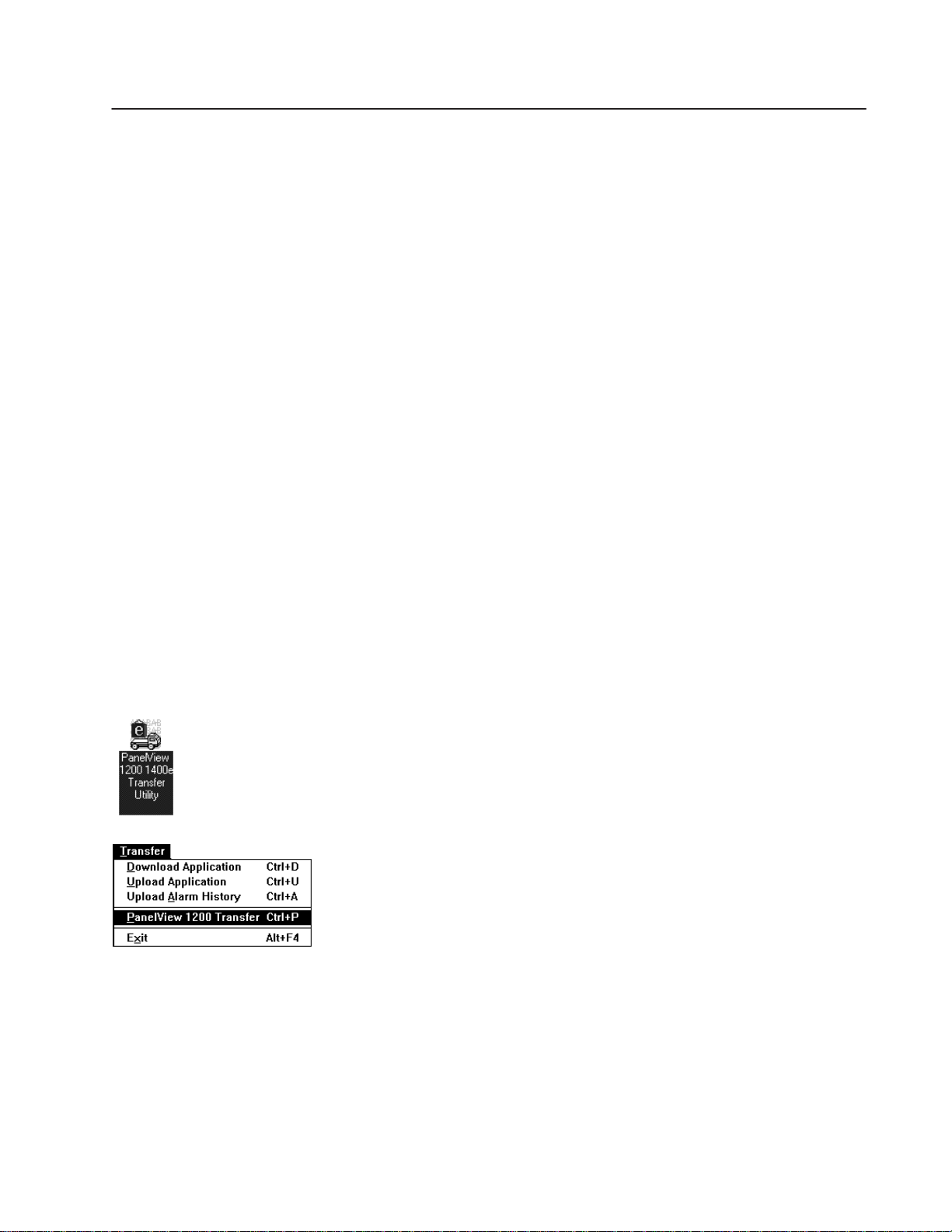
The PanelView 1200/1400e Transfer Utility can be accessed by
clicking the transfer utility icon in Windows NT, Windows 3.1, or
Windows 95. The PanelView 1200 Transfer Utility can only be
accessed if you are running the transfer utility from Windows 3.1 or
Windows 95.
• PanelView 1200/1400e Transfer Utility—this is the main
application, and is activated when you double-click the icon
shown here
• PanelView 1200 Transfer Utility—this application, available
only in versions earlier than Version 4, is included for transferring
files to and from the PanelView 1200 terminals. The PanelView
1200 Transfer Utility is installed with the PanelView 1200/1400e
Transfer Utility. Activate this utility by choosing PanelView 1200
Transfer from the Transfer menu. Context-sensitive help is not
available for this utility. Refer to the PanelView 1200 Transfer
Utility User Manual (Publication Number 2711-811) for
operational details.
Publication 2711E-6.8 – January 1998
Page 10
1–2 Introducing the PanelView 1200/1400e Transfer Utility
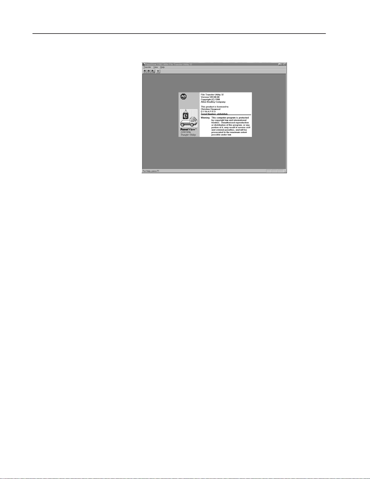
The following screen is displayed after you activate the application.
Types of Applications
"
FTU
Note: PanelBuilder software does not need to be installed in order to
do file transfers. You need only the PanelView 1200/1400e Transfer
Utility.
You can transfer the following types of terminal application files
using the PanelView 1200/1400e Transfer Utility:
• files whose names end in .pvd— files created in PanelBuilder
1400e for Windows. Files are created and edited as *.pvc. You
then must save the file as a *.pvd to download it. These are
PanelView enhanced 1200 (Series F and later) and
1000e/1200e/1400e terminal files.
• files whose names end in .cfg—files created in PanelBuilder
Development Software for DOS and PanelBuilder 1200 for
Windows. These are PanelView 1200 terminal files.
PanelBuilder 1200 can create application files in several different
formats. Make sure the *.cfg format is used. See the PanelBuilder
1200 for Windows User Manual for more information about
saving application files in *.cfg format.
Publication 2711E-6.8 – January 1998
Page 11

1–3Introducing the PanelView 1200/1400e Transfer Utility
Types of Transfers
Methods of Downloading and Uploading Applications and Alarm History Files
FTU32
The PanelView 1200/1400e Transfer Utility does the following types
of transfers:
• downloading an application file—Transferring an application
file from the development computer to a PanelView terminal so
the application can be run. PanelView 1200 and PanelView
1000e/1200e/1400e applications can be downloaded.
• uploading an application file—Transferring an application file
from the PanelView terminal to the development computer that
the PanelView 1200/1400e Transfer Utility is on so the
application can be edited or archived. PanelView 1200 and
PanelView 1000e/1200e/1400e applications can be uploaded.
• uploading alarm history files—Transferring the Alarm History
File from the PanelView terminal to the development computer so
the files can be analyzed or archived. Only PanelView enhanced
1200 (Series F and later) and 1000e/1200e/1400e V02.00.00 and
later Alarm History files can be uploaded.
There are three methods for downloading and uploading applications
and alarm history files:
• Serial (RS-232) Upload/Download—With the
Upload/Download cable (A-B Catalog Number 2711-NC1 for
PanelView 1200e/1400e terminals; A-B Catalog Numbers
2706-NC13, 2711-NC13, or 2711-NC14 for PanelView 1000e
terminals), you can upload or download applications or upload
Alarm History files directly by connecting the serial ports on the
computer and PanelView terminal. This is a serial file transfer.
• Network Direct Upload/Download—You can upload
applications or Alarm History files once you have connected the
PanelView terminal and computer to the DH+ or ControlNet
network. You can download applications between the computer
running the Transfer Utility and the PanelView terminal over the
ControlNet or DH+ network without taking the terminal out of
Run mode. Also, you can print from the PanelView terminal
without changing the serial cabling of the terminal.
For PanelView 1000e/1200e/1400e terminals, in order to do
Direct Network downloads, you must use RSLinx drivers.
RSLinx is included on floppy disks with your PanelBuilder 1400e
software package (A-B Catalog Number 2711E-ND1) or Transfer
Utility software package (A-B Catalog Number 2711E-ND7); you
must install RSLinx separately. Refer to the table in Chapter 5 for
a complete list of hardware and driver requirements.
Publication 2711E-6.8 – January 1998
Page 12

1–4 Introducing the PanelView 1200/1400e Transfer Utility
FTU
"
FTU 32
For PanelView enhanced 1200 (Series F and later) and
1000e/1200e/1400e terminals, in order to do Direct Network
downloads, you must use INTERCHANGE or WINtelligent
LINX drivers. Contact your A-B Sales Representative for details.
Refer to the table in Chapter 5 for a complete list of hardware and
driver requirements.
Note: Refer to the PanelView 1000e, 1200e, and 1400e Operator
Terminals User Manual for information about the ControlNet
Communication Interface Card requirements for uploading and
downloading over ControlNet.
• Remote I/O Pass-Through—Using Remote I/O Pass-Through,
you can upload application files and Alarm History files over
Remote I/O and then over DH+, ControlNet, or Ethernet.
You can download a Remote I/O application between the
PanelView terminal and computer without taking the terminal out
of Run mode or changing the terminal’s serial cabling. Also, you
can print from the PanelView terminal without changing the serial
cabling of the terminal.
For PanelView 1000e/1200e/1400e terminals, in order to do
Remote I/O Pass-Through downloads, you must use RSLinx
drivers. RSLinx is included with your Transfer Utility software
package; however, you must install RSLinx separately. Refer to
the table in Chapter 5 for a complete list of hardware and driver
requirements.
Transferring Tips
FTU
For PanelView enhanced 1200 (Series F and later) and
1000e/1200e/1400e terminals, in order to do Remote I/O
Pass-Through downloads, you must use INTERCHANGE or
WINtelligent LINX drivers. Refer to the table in Chapter 5 for a
complete list of hardware and driver requirements.
Read this section when preparing to transfer an application.
General
For file transfers over ControlNet, DH+, or Remote I/O
•
Pass-Through, be sure the PanelView terminal address and
control byte is correct, otherwise the transfer could corrupt the
PLC logic.
• For all direct transfers (serial or network direct), the
communication parameters of the PanelView 1200/1400e
Transfer Utility driver must match those being used by the
PanelView terminal.
• Do not interrupt a download by cycling power during the
operation.
Publication 2711E-6.8 – January 1998
Page 13

1–5Introducing the PanelView 1200/1400e Transfer Utility
• Do not try to download application files from two development
computers to the same location at the same time. Results are
unpredictable.
• The PanelView terminal ignores all operator inputs and PLC
outputs during the download. The current application screen is
removed and the Transfer screen and progress bar are displayed.
• The rack assignments (for Remote I/O applications) or terminal
network address (for DH+, ControlNet, and Ethernet) remain as
they were set for the previous current application until the
download is complete.
For PanelView 1200 Terminal Transfers
When you upload an application from the PanelView 1200 terminal
using the PanelView 1200 Transfer Utility, the current values for the
object addresses are uploaded. Refer to the PanelView 1200 Transfer
Utility User Manual (Publication Number 2711-811) for more
information.
For PanelView 1000e, 1200e, or 1400e Terminals Transfers
Before you download to PanelView 1000e, 1200e, or 1400e
•
terminals, check the size of the application file (the .pvd file) to
make sure it will fit in the terminal’s memory or on the PCMCIA
memory card. For more information, refer to Chapter 3, Working
with Applications in the PanelBuilder 1400e Configuration
Software for Windows User Manual (Publication Number
2711E-819).
• When you upload an application from the PanelView 1000e,
1200e, or 1400e terminals using the PanelView 1200/1400e
Transfer Utility, the initial tag values of the application are
uploaded, not its current values.
• When you upload an application from the PanelView 1000e,
1200e, or 1400e terminals to edit it in PanelBuilder, any of the
following items that were originally in the downloaded
application are not uploaded:
• unused nodes
• unused scan classes
• unused tags
• unused tag folders
• unused graphic images
• tag descriptions
• variable names
• comments in expressions
Publication 2711E-6.8 – January 1998
Page 14

1–6 Introducing the PanelView 1200/1400e Transfer Utility
• When the PanelView 1200/1400e Transfer Utility uploads a file,
it creates a *.pvd file. PanelBuilder can open the .pvd file to
create a .pvc file. When .pvd files are opened in PanelBuilder, the
.pvd files are always regenerated as .pvc files with a private tag
database.
FTU
PanelView 1200/1400e Transfer Utility and INTERCHANGE
The PanelView 1200/1400e Transfer Utility supports the full range
of INTERCHANGE serial and network drivers. The
INTERCHANGE drivers allow ports and communication devices to
be shared between PanelBuilder and other Allen-Bradley products
such as the 6200-series PLC-5 Programming Software and
PanelBuilder 900. INTERCHANGE drivers also support
communication cards such as the KT and PCMK for DH+
communication. Contact your Allen-Bradley representative for more
information on INTERCHANGE.
To use the INTERCHANGE drivers, install INTERCHANGE before
setting up file transfer communications. The transfer utility displays
the INTERCHANGE drivers as driver options, but you can use them
only if INTERCHANGE is installed. The driver options
INTERCHANGE Port 1 to INTERCHANGE Port 8 map to the eight
ports supported by INTERCHANGE.
If you have INTERCHANGE Version 6.1.0 or later, you can select
one of these options and call up the INTERCHANGE Device
Configuration Utility from the PanelView 1200/1400e Transfer
Utility. From the configuration utility you can view and change the
configuration of any of the eight INTERCHANGE ports. Make sure
the port you select for your driver is configured correctly for the
communication device and settings. Refer to the INTERCHANGE
Device Configuration Utility user documentation for information on
using the utility.
Publication 2711E-6.8 – January 1998
If your version of INTERCHANGE is earlier than 6.1.0, you must
view and configure the ports outside of the PanelView 1200/1400e
Transfer Utility. Refer to your INTERCHANGE user documentation.
Again, make sure the port you select is configured correctly for your
communication device and settings.
Page 15

1–7Introducing the PanelView 1200/1400e Transfer Utility
FTU
PanelView 1200/1400e Transfer Utility and WINtelligent LINX
The PanelView 1200/1400e Transfer Utility supports WINtelligent
LINX network drivers, Version 5.20.00 or later. The PanelView
1200/1400e Transfer Utility supports a subset of the WINtelligent
LINX drivers—those used for appropriate DH+, ControlNet, and
serial transfers. You can use these drivers to transfer files over DH+,
ControlNet, RIO Pass-Through, or serial connection networks.
Contact your Allen-Bradley Sales Representative for more
information on WINtelligent LINX.
To use the WINtelligent LINX drivers, install them before setting up
transfer communications. The PanelView 1200/1400e Transfer
Utility displays the WINtelligent LINX drivers as driver options, but
you can use them only if they are installed. Make sure the driver you
select is configured correctly for the communication device and
settings. You can open the WINtelligent LINX configuration utility
from the Transfer Utility to configure your selected driver.
Refer to the WINtelligent LINX for Allen-Bradley Programmable
Controllers User’s Guide (Publication Number 9352-WABUG) for
complete information.
FTU32
Important: The PanelView 1200/1400e Transfer Utility works with
INTERCHANGE only, WINtelligent LINX only, or
with both INTERCHANGE and WINtelligent LINX
installed on the same computer.
PanelView 1200/1400e Transfer Utility and RSLinx
The Transfer Utility does support RSLinx network drivers, Version
1.7 or later. RSLinx is included on floppy disks with your
PanelBuilder 1400e software package (A-B Catalog Number
2711E-ND1) or Transfer Utility software package (A-B Catalog
Number 2711E-ND7). The PanelView 1200/1400e Transfer Utility
supports a subset of the RSLinx drivers—those used for appropriate
DH+, ControlNet, Ethernet, or serial transfers. You can use these
drivers to transfer files over DH+, ControlNet, Ethernet, Remote I/O
Pass-Through, or serial connection networks. Refer to the RSLinx
user documentation for more information.
If you use RSLinx drivers, install them before setting up transfer
communications. The PanelView 1200/1400e Transfer Utility
displays the RSLinx drivers as driver options, but you can use them
only if they are installed. Make sure the driver you select is
configured correctly for the communication device and settings. You
can open the RSLinx configuration utility from the Transfer Utility
to configure your selected driver.
Publication 2711E-6.8 – January 1998
Page 16

Working with the PanelView
1200/1400e Transfer Utility
This chapter provides instructions for setting up and using the
PanelView 1200/1400e Transfer Utility, including:
• minimum hardware and software requirements
• installing and starting the PanelView 1200/1400e Transfer Utility
• exiting from the PanelView 1200/1400e Transfer Utility
The PanelView 1200/1400e Transfer Utility has context-sensitive
online help that you can access at any time by pressing
keyboard. For general help, click the icon
in the utility’s
toolbar.
For information on how to set up and use the PanelView 1200
Transfer Utility, see the PanelView 1200 Transfer Utility User
Manual (Publication Number 2711-811).
F1 on your
System Requirements
You need the following hardware and software to install the
PanelView 1200/1400e Transfer Utility from the disks.
Hardware and Software Requirements
Requirements FTU FTU32
Hardware
Software Microsoft Windows Version 3.x or Windows 95 Microsoft Windows NT Version 4.0, or Windows 95
A personal computer with a 25-MHz, 386-DX or higher
microprocessor, with a recommended minimum of
8-MB RAM
CD-ROM drive (recommended) CD-ROM drive (recommended)
A fixed disk with 10 MB of free space A fixed disk with 10 MB of free space
An 8-MB swap file An 8-MB swap file
A 3.5-inch high-density (1.44-MB) disk drive A 3.5-inch high-density (1.44-MB) disk drive
An RS-232 serial port for uploading or downloading
applications, or other communication cards listed later
in this chapter
A standard VGA (640 by 480) display adapter
configured for at least 16 colors
A mouse or pointing device supported by Windows A mouse or pointing device supported by Windows
Microsoft MS-DOS Version 3.3 or above
A personal computer with a 50-MHz, 486-DX or higher
microprocessor, with a recommended minimum of
16-MB RAM
An RS-232 serial port for uploading or downloading
applications, or other communication cards listed later
in this chapter
A standard VGA (640 by 480) display adapter
configured for at least 16 colors
Publication 2711E–6.8 – January 1998
Page 17

2–2
PanelBuilder Applications
For details on PanelBuilder, see Types of Applications in Chapter 1.
PanelView Terminals
You must have one or more PanelView terminals. Table 2.B lists the
terminal products and their catalog numbers.
PanelView Terminal Products and Catalog Numbers
Catalog Number Product Description
2711E-T10C6
2711E-K10C6 1000e Keypad Terminal Color display, clip mount, NEMA 4X
2711E-T10C7 1000e Touch Screen Terminal ControlNet 1.25 enhanced 2711E-T10C6
2711E-K10C7 1000e Keypad Terminal ControlNet 1.25 enhanced 2711E-K10C6
2711E-T10C15 1000e Touch Screen Terminal ControlNet 1.5 enhanced 2711E-T10C6
2711E-K10C15 1000e Keypad Terminal ControlNet 1.5 enhanced 2711E-K10C6
2711-KA1 1200 Keypad Terminal Amber display
2711-KC1 1200 Keypad Terminal Color display
2711-TA1, TA4 1200 Touch Screen Terminal Amber display
2711-TC1, TC4 1200 Touch Screen Terminal Color display
2711E-T12C6 1200e Touch Screen Terminal Color display, clip mount, NEMA 12
2711E-T12C4 1200e Touch Screen Terminal Color display, stud mount, NEMA 4X (Indoor
2711E-K12C6 1200e Keypad Terminal Color display, stud mount, NEMA 4X (Indoor
2711E-K12C6L2 1200e Keypad Stainless Steel Terminal Color display, stud mount, stainless steel
2711E-T14C6 1400e Touch Screen Terminal Color display, stud mount, NEMA 4X (Indoor
2711E-K14C6 1400e Keypad Terminal Color display, stud mount, NEMA 4X (Indoor
2711E-T14C7 1400e Touch Screen Terminal ControlNet 1.25 enhanced 2711E-T14C6
2711E-K14C7 1400e Keypad Terminal ControlNet 1.25 enhanced 2711E-K14C6
2711E-T14C15 1400e Touch Screen Terminal ControlNet 1.5 enhanced 2711E-T14C6
2711E-K14C15 1400e Keypad Terminal ControlNet 1.5 enhanced 2711E-K14C6
2711-NC1 Upload/Download Cable For 1200/1200e/1400e terminals. Includes a
1000e Touch Screen Terminal Color display, clip mount, NEMA 4X
terminal
terminal
terminal
terminal
use only)
use only)
bezel, NEMA 4X (Indoor use only)
use only)
use only)
terminal
terminal
terminal
terminal
9-pin or 25-pin RS-232 serial cable
(Upload/Download cable) to transfer files
between terminal and development
computer. The cable is 10 ft (3.1 m) long.
Publication 2711E–6.8 – January 1998
Page 18

2–3
Catalog Number DescriptionProduct
2711-NC13
2711-NC14 Upload/Download Cable For 1000/1000e terminals only. Includes a
2706-NC13 Upload/Download Cable For 1000/1000e terminals only. Includes a
Upload/Download Cable For 1000/1000e terminals only. Includes a
9-pin RS-232 serial cable (Upload/Download
cable) to transfer files between terminal and
development computer. The cable is 16.4 ft
(5 m) long.
9-pin RS-232 serial cable (Upload/Download
cable) to transfer files between terminal and
development computer. The cable is 32.7 ft
(10 m) long.
9-pin RS-232 serial cable (Upload/Download
cable) to transfer files between terminal and
development computer. The cable is 10 ft
(3 m) long.
Equipment Required for Transferring Applications
FTU32
FTU
This section describes the equipment required to perform the
following application transfers:
• serial transfer
• DH+ network direct transfer
• ControlNet network direct transfer
• Remote I/O Pass-Through transfer
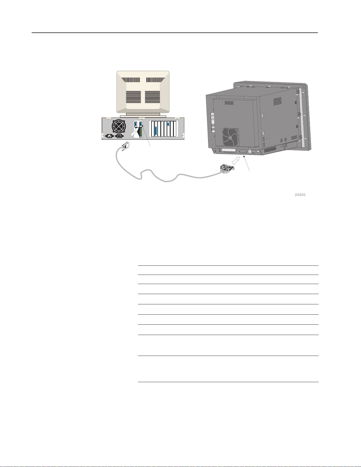
Serial Upload/Download
To transfer applications serially, you need an RS-232 Serial
(Upload/Download) cable (A-B Catalog Numbers 2706-NC13,
2711-NC13, 2711-NC14 for PanelView 1000e terminals; 2711-NC1
for PanelView 1200/1200e/1400e terminals) for connecting the
computer to the PanelView terminal.
The 1200e/1400e Transfer Utility can transfer applications serially
without using the RSLinx drivers.
Both the 1200 and 1200e/1400e Transfer Utility can transfer
applications serially without using INTERCHANGE or WINtelligent
LINX drivers. For information on PanelView 1200 serial transfers,
see the PanelView 1200 Transfer Utility User Manual (Publication
Number 2711-811).
Publication 2711E–6.8 – January 1998
Page 19
2–4
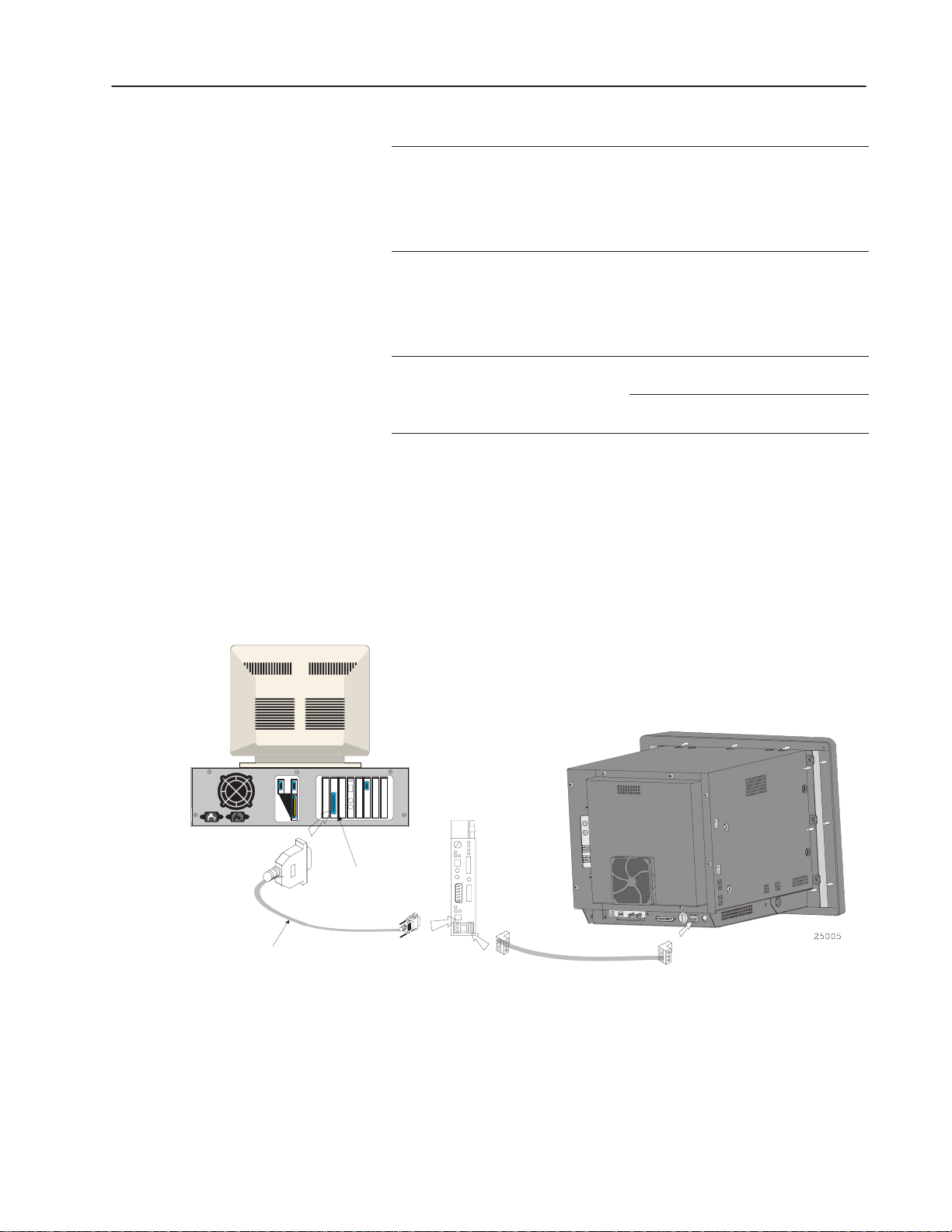
Figure 2.1 Connecting the Upload/Download Cable
Computer running the PanelView
1200/1400e Transfer Utility
PanelView 1400e Touch Screen Terminal
RS-232 Serial Port
9-pin
RS-232
Upload/Download Cable
(NC1)
25-pin
DH+ Network Direct Transfers
You need one of the following Allen-Bradley Data Highway Plus
(DH+) interface modules to transfer applications over a DH+
network:
FTU FTU32
1770-KF2/1785-KE
1784-KL 1784-KL
1784-KT
1784-KT2
1784-KTK1
1784-PCMK
1784-KTX
For 1000e/1200e/1400e terminals,
INTERCHANGE and WINtelligent LINX
drivers are required.
For 1200 terminals, Pass-Through drivers
are built into the Transfer Utility. See the
PanelView 1200 Transfer Utility User
Manual (Publication Number 2711-811).
1770-KF2/1785-KE
1784-KT
1784-KT2
1784-KTK1
1784-PCMK
1784-KTX
For 1000e/1200e/1400e terminals, RSLinx
drivers are required.
For 1000e/1200e/1400e terminals, RSLinx
drivers are required.
Publication 2711E–6.8 – January 1998
To download over a DH+ network, the development computer and
PanelView terminal can be on the same network or on two different
DH+ networks bridged by a DH+ network bridge.
Page 20
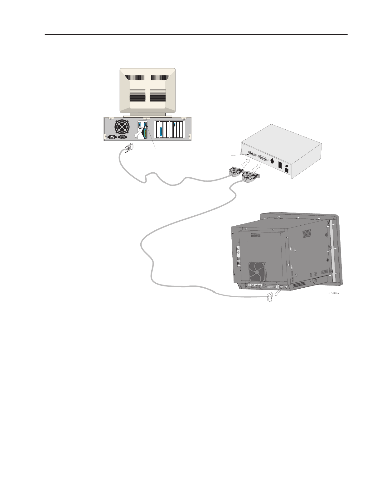
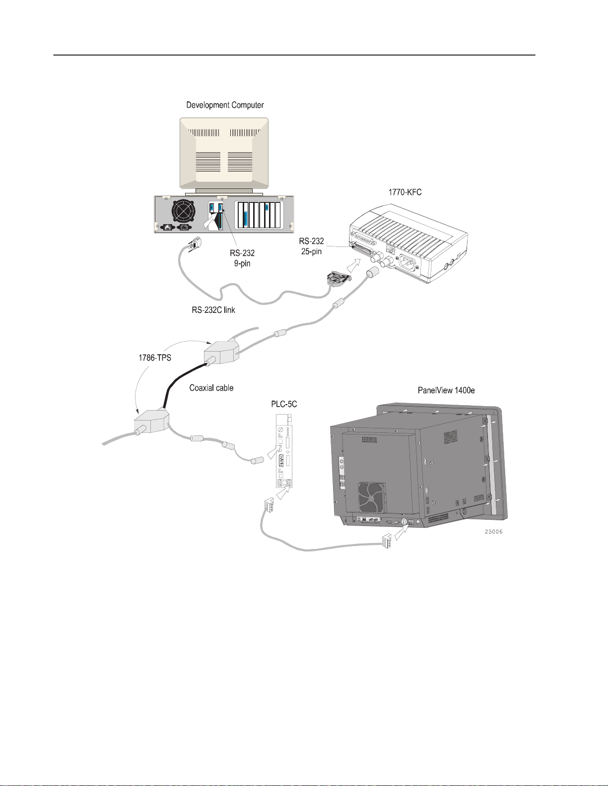
Figure 2.2 DH+ Network Direct Download (with KF2)
Development Computer
2–5
1770-KF2
RS-232 Serial Port
9-pin
RS-232C Link
DH+
RS-232
25-pin
PanelView 1400e
Publication 2711E–6.8 – January 1998
Page 21
2–6
Development Computer
Figure 2.3 DH+ Network Direct Download (with 1784-KT
card)
PanelView 1400e
PLC-5
1784-KT
1784-CP
Cable
DH+
DH+
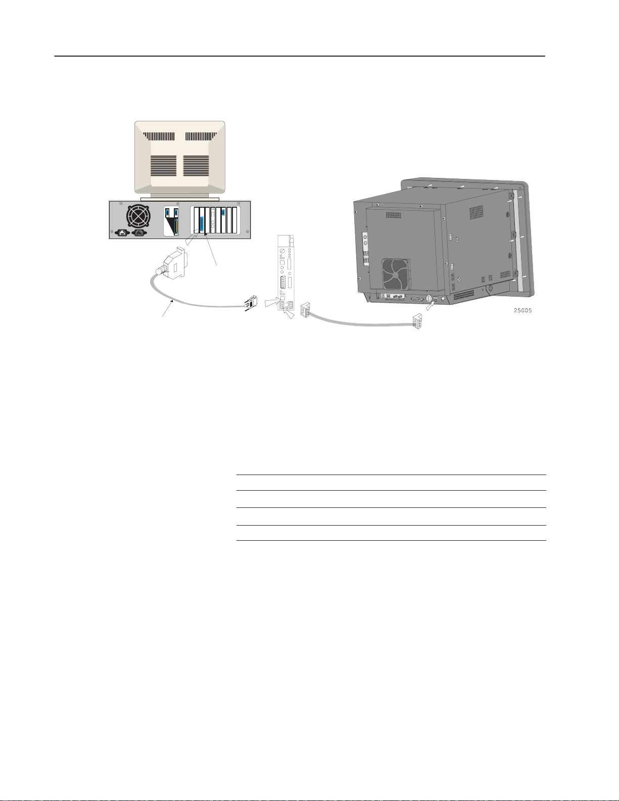
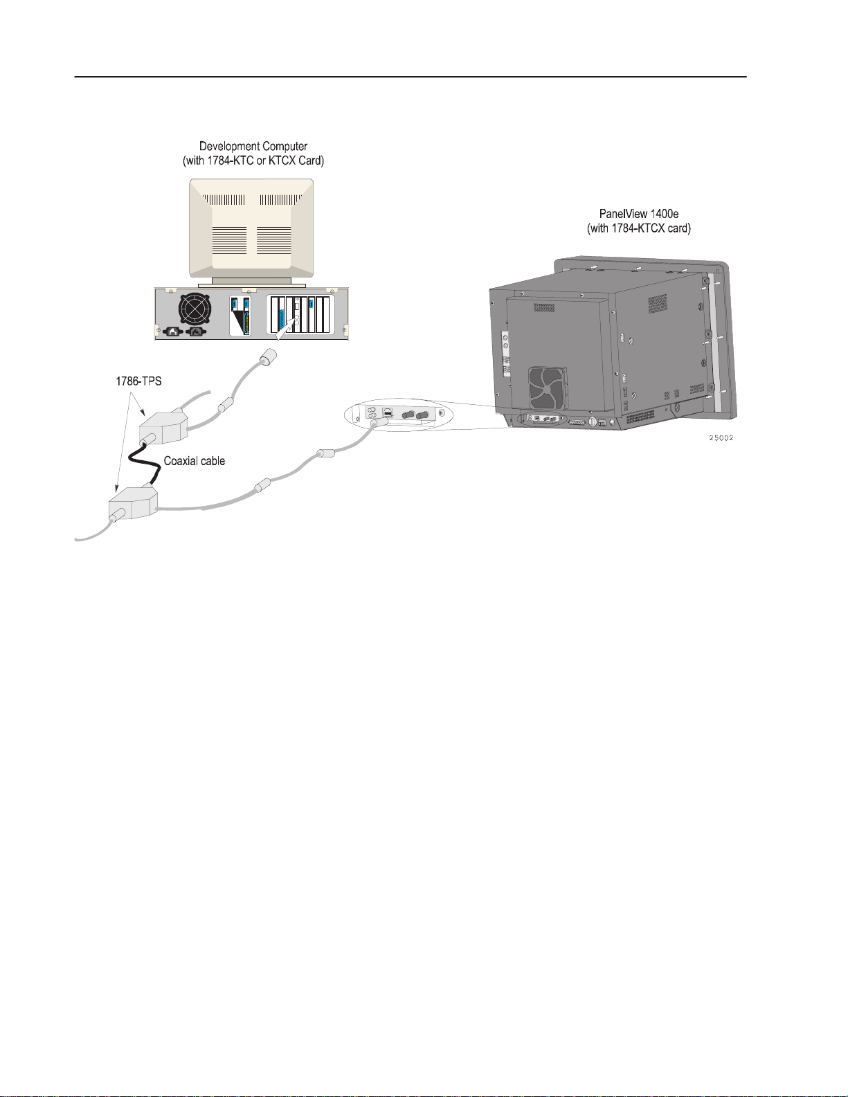
ControlNet Network Direct Transfers
The 1200/1200e terminals are not compatible with ControlNet. You
need the following Allen-Bradley ControlNet Interface modules to
transfer applications over ControlNet:
FTU FTU32
1784-KTCX (Series B or later)
1784-KTC
1770-KFC 1770-KFC
INTERCHANGE or WINtelligent LINX RSLinx
To download over a ControlNet network, the PanelView terminal
must be active on the same network as the development computer.
1784-KTCX (Series B or later)
1784-KTC
Publication 2711E–6.8 – January 1998
Page 22
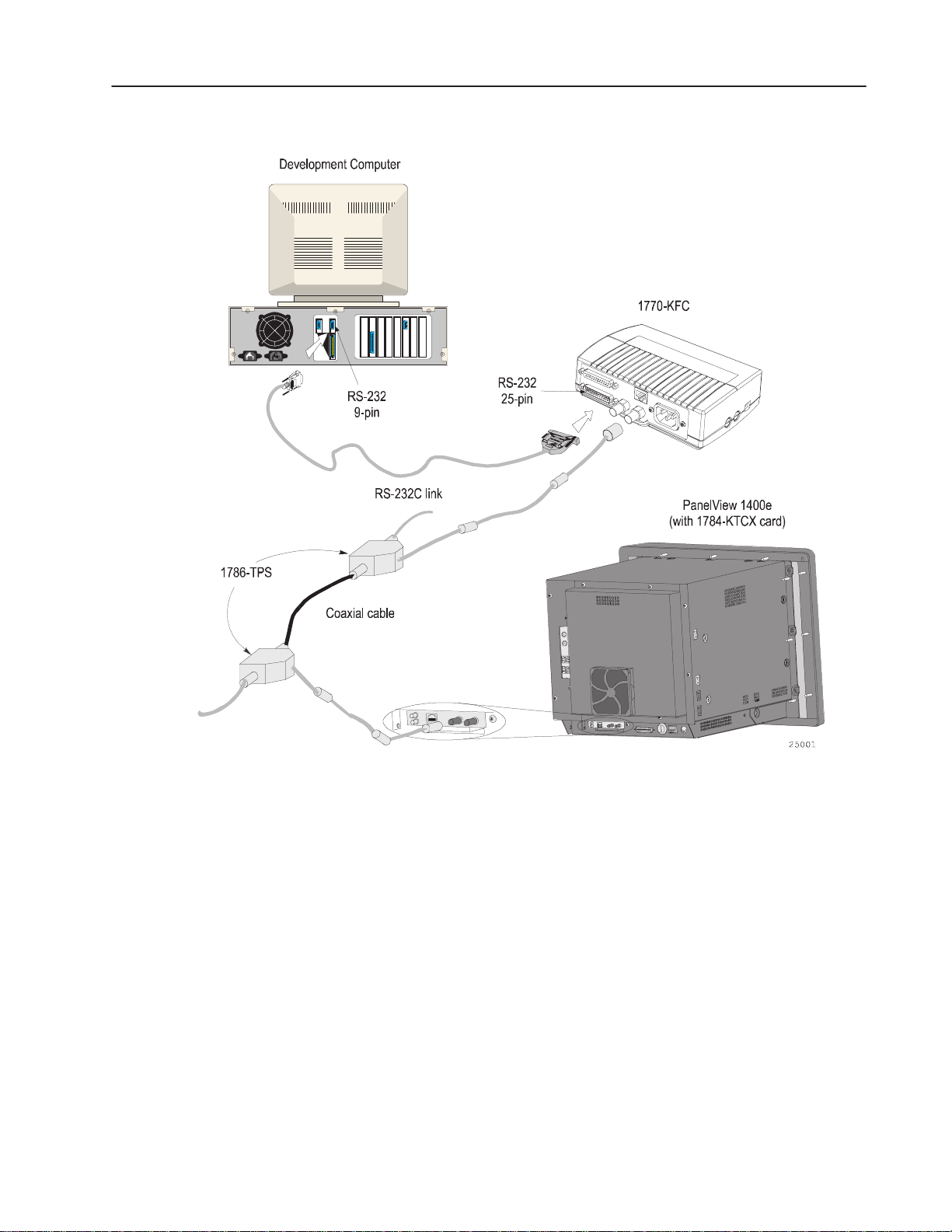
Figure 2.4 ControlNet Network Direct Download (with
1770-KFC)
2–7
Publication 2711E–6.8 – January 1998
Page 23
2–8
Figure 2.5 ControlNet Network Direct Download (with
1784-KTC or KTCX card)
Remote I/O Pass-Through Transfers
The Remote I/O Pass-Through feature enables you to download a
PanelBuilder Remote I/O application file from your computer over
the Data Highway Plus (DH+), ControlNet, or Ethernet networks and
then over the Remote I/O network, to a PanelView terminal. You can
do this without connecting the serial cable to the terminal and
without going from terminal to terminal with a PC.
You need the same equipment for Remote I/O Pass-Through
transfers over either DH+ or ControlNet as listed previously for the
two networks. In addition, you need one of the following:
Publication 2711E–6.8 – January 1998
Page 24
2–9
RC A G o telli ent L is
ed
FTU FTU32
For a DH+ transfer, a PLC-5 or SLC-5/04
processor is required (for PLC/SLC
series/revision requirements, refer to
Chapter 5 of the PanelView 1000e, 1200e,
and 1400e Operator Terminals User
Manual)
For a ControlNet transfer, a PLC-5
processor is required (for PLC
series/revision requirements, refer to
Chapter 5 of the PanelView 1000e, 1200e,
and 1400e Operator Terminals User
Manual)
For 1000e/1200e/1400e terminals,
INTERCHANGE or WINtelligent LINX is
requir
For a DH+ transfer, a PLC-5 or SLC-5/04
processor is required (for PLC/SLC
series/revision requirements, refer to
Chapter 5 of the PanelView 1000e, 1200e,
and 1400e Operator Terminals User
Manual)
For a ControlNet transfer, a PLC-5
processor is required (for PLC
series/revision requirements, refer to
Chapter 5 of the PanelView 1000e, 1200e,
and 1400e Operator Terminals User
Manual)
For an Ethernet transfer, a PLC-5 processor
is required
For 1000e/1200e/1400e terminals, RSLinx
is required
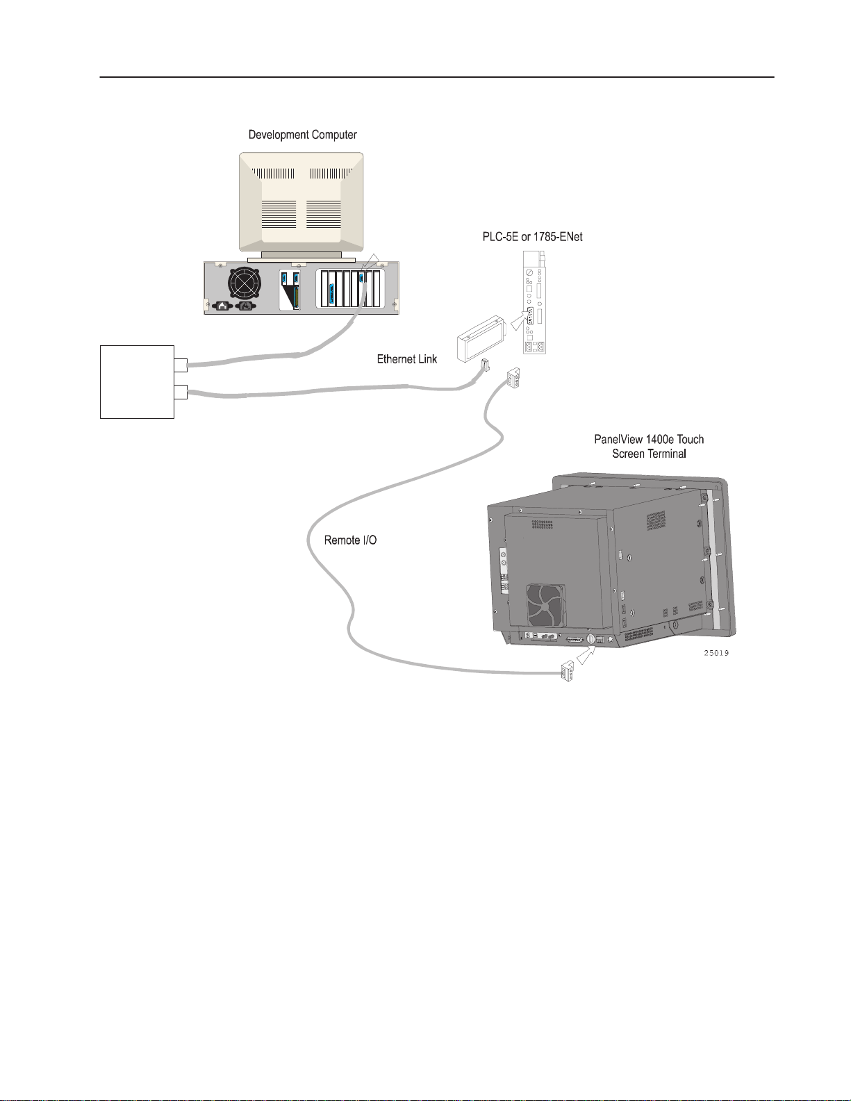
Figures 2.6 and 2.7 show how the application file is transferred from
the development computer to the PLC controller and then to the
PanelView terminal. Figure 2.8 shows how the application file is
transferred through an Ethernet link, over the Remote I/O network,
and then to the PanelView terminal.
Development Computer
1784-KT
1784-CP
Cable
Figure 2.6 Remote I/O Pass-Through on a DH+ Network
PanelView 1400e
PLC-5
DH+
RIO
Publication 2711E–6.8 – January 1998
Page 25
2–10
Figure 2.7 Remote I/O Pass-Through on a ControlNet
Network (with 1770-KFC)
Publication 2711E–6.8 – January 1998
RIO
Page 26
10 BASET
HUB or
Patch Panel
2–11
Figure 2.8 Ethernet Pass-Through
ISA Ethernet Card
Ethernet Transceiver
General Installation Information
You may install the PanelView 1200/1400e Transfer Utility software
using the CD-ROM provided in the PanelBuilder 1400e software kit
(A-B Catalog Number 2711E-ND1) or disks provided in the
PanelView 1200/1400e Transfer Utility software package (A-B
Catalog Number 2711E-ND7).
You may also obtain floppy disks of the PanelView 1200/1400e
Transfer Utility software by creating them from the PanelBuilder
1400e CD or by sending in the Disk Request Fax Back Form
available in the PanelBuilder 1400e software package (A-B Catalog
Number 2711E-ND1).
For instructions on how to create floppy disks of the software from
the PanelBuilder 1400e CD, refer to the Readme file, titled
Floppies.txt, in the root directory of the PanelBuilder 1400e CD.
Publication 2711E–6.8 – January 1998
Page 27

2–12
The CD-ROM includes two install versions for the PanelView
1200/1400e Transfer Utility software:
• Version 3—This version offers you the PanelView 1200/1400e
Transfer Utility (FTU) on an operating system that uses Windows
3.1 or later, or Windows 95. Version 3 supports INTERCHANGE
and WINtelligent LINX drivers for PanelView 1000e, 1200,
1200e, and 1400e file transfers.
• Version 4—This version offers you the PanelView 1400e Transfer
Utility (FTU32) software on an operating system that uses
Windows 95 or Windows NT. Version 4 supports RSLinx drivers
for PanelView 1000e, 1200e, and 1400e file transfers.
If your operating system is Windows 3.1 or later, the CD-ROM will
install Version 3. If your operating system is Windows 95, you have
a choice of installing Version 3 or Version 4. If your operating
system is Windows NT, the CD-ROM will install Version 4.
Installing FTU32 from CD-ROM on Windows NT or Windows 95
PanelView 1200/1400e Transfer Utility Version 4 (FTU32) is
provided on the PanelBuilder 1400e CD-ROM. The software
installation program creates a directory on your hard drive for the
FTU32 and copies all necessary files to it. By default, the drive and
directory is C:\AB\PB1400E\FTU32. You can change this default.
T o install FTU32:
1. Start Windows 95 or Windows NT. If you’re already in Windows,
close all open Windows applications.
2. Insert the CD-ROM in the drive.
The CD-ROM begins to run automatically.
3. If the install does not start automatically, choose Run from the
Start button and select setup.exe from the CD-ROM drive; or
select setup.exe from Windows Explorer.
4. In the Welcome dialog box, choose Next.
5. If you are installing on Windows 95, the Select Components
dialog box appears.
Publication 2711E–6.8 – January 1998
Page 28

2–13
The CD-ROM includes two install versions for the File Transfer
Utility software:
• Version 3—This version offers you File Transfer Utility on an
operating system that uses 3.1 or later, or Windows 95.
Version 3 supports PanelView application file transfers over
networks using INTERCHANGE and WINtelligent LINX
software drivers.
• Version 4—This version offers you File Transfer Utility on an
operating system that uses Windows 95 or Windows NT.
Version 4 supports PanelView application file transfers over
networks using RSLinx software drivers.
Version 4 for the Windows 95 operating system is recommended.
If you choose Version 3, refer to “Installing FTU from CD-ROM
on Windows 95 or Windows 3.x” in this chapter for instructions.
Otherwise, continue by selecting Version 4, and then choose
Next.
If you are installing on Windows NT, the Select Components
dialog box does not appear. Version 4 is automatically selected.
6. In the Choose Applications dialog box, choose File Transfer
Utility as the application you want to install. You can choose
more than one application to install. Then choose Next.
Publication 2711E–6.8 – January 1998
Page 29

2–14
7. In the registration window, enter your user name and company
name. After you enter the required information, choose Next.
8. In the confirmation window, verify the user information you have
entered. Select Yes to proceed or No to edit the user information.
9. In the Welcome dialog box for the File Transfer Utility, it
recommends that you close all open Windows applications. If you
have done that, choose Next.
If you have chosen other applications to install, the first selected
application automatically begins to install.
10. In the FTU32 registration window, enter the serial number. You
can obtain registration information from the software registration
card that is in your PanelBuilder 1400e package (A-B Catalog
Number 2711E-ND1) or PanelView 1200/1400e Transfer Utility
package (A-B Catalog Number 2711E-ND7). Choose Next.
11. Choose the drive and directory in which the FTU32 will be
installed. By default, this is C:\AB\PB1400E\FTU32. To change
the destination drive or directory, type the new drive and/or
directory in the Program Files field. Then choose Next.
12. Choose the program folder (program group) in which you want to
install the FTU32’s icons, which includes a Readme file icon, the
Transfer Utility icon, and an Uninstall icon. By default, the icons
are installed in the PanelBuilder 1400e program folder. Then
choose Next.
Publication 2711E–6.8 – January 1998
13. Choose whether the installation utility will modify the
AUTOEXEC.BAT file.
If you are installing on Windows 95, the entry
C:\Progra~1\Rockwe~1\RDM;%Path%
is required in the PATH variable for the FTU32 to work correctly.
Page 30

2–15
If you are installing on Windows NT, the entry
C:\Program Files\Rockwell Software\RDM
is required in the PATH variable in the Environment tab of the
System Properties dialog.
Choose Next to approve and continue.
14. The setup utility shows a summary of the choices you made in the
preceding dialog boxes. To make any changes, choose the Back
button. Otherwise, choose Next to begin the installation.
15. After all the applications have completed installing, you will be
prompted to reboot your computer. You may reboot immediately
or later, but you must reboot before you can run the File Transfer
Utility or other applications successfully.
After you finish installing the File Transfer Utility and you want
to upload or download PanelView files over the PLC networks,
you also need to install RSLinx Lite software, which is provided
on 3.5-inch floppy disks. See the RSLinx user documentation
provided for installation procedures.
Installing FTU from CD-ROM on Windows 95 or Windows 3.x
Do not cancel the installation while it is in progress. If you want to
undo the installation, let the installation finish, then use the Uninstall
Transfer Utility to remove all the installed files and to update the
registration.
PanelView 1200/1400e Transfer Utility Version 3 (FTU) is provided
on the PanelBuilder 1400e CD-ROM. The software installation
program creates a directory on your hard drive for the FTU and
copies all necessary files to it. By default, the drive and directory is
C:\AB\PB1400E\FTU. You can change this default.
T o install FTU:
1. Start Windows 95 or Windows 3.x. If you’re already in Windows,
close all open Windows applications.
2. Insert the CD-ROM in the drive.
The CD-ROM begins to run automatically.
3. If the install does not start automatically and you are running on
Windows 95, choose Run from the Start button and select
setup.exe from the CD-ROM drive; or select setup.exe from
Windows Explorer.
Publication 2711E–6.8 – January 1998
Page 31

2–16
If you are running on Windows 3.x, choose Run from the File
menu. In the Run windows, type:
d:setup
where d is the drive containing the File Transfer Utility
CD-ROM, and press Enter.
4. In the Welcome dialog box, choose Next.
5. If you are installing on Windows 95, the Select Components
dialog box appears. Choose Version 3, and then choose Next.
If you are installing on Windows 3.x, the Select Components
dialog box does not appear. Version 3 is automatically selected.
6. In the Choose Applications dialog box, choose File Transfer
Utility as the application you want to install. You can choose
more than one application to install. Then choose Next.
7. In the Welcome dialog box for the File Transfer Utility, it
recommends that you close all open Windows applications. If you
have done that, choose Next.
Publication 2711E–6.8 – January 1998
8. In the registration window, enter the required information. You
can obtain registration information from the software registration
card that is in your PanelBuilder 1400e package. Choose Next.
Page 32

2–17
9. Choose the drive and directory in which the FTU will be
installed. By default, this is C:\AB\PB1400E\FTU. To change the
destination drive or directory, type the new drive and/or directory
in the Program Files field. Then choose Next.
10. Choose the program folder (program group) in which you want to
install the FTU’s icons, which includes a Readme file icon, the
Transfer Utility icon, and an Uninstall icon. By default, the icons
are installed in the PanelBuilder 1400e program folder. Then
choose Next.
11. Choose whether the installation utility will modify the
AUTOEXEC.BAT file. The entry
C:\RSI\CMN
is required in the PATH variable for the FTU to work correctly.
Then choose Next.
12. The setup utility shows a summary of the choices you made in the
preceding dialog boxes. To make any changes, choose the Back
button. Otherwise, choose Next to begin the installation.
Installing FTU32 from Floppy Disks on Windows NT or Windows 95
13. After all the applications have completed installing, you will be
prompted to reboot your computer. You may reboot immediately
or later, but you must reboot before you can run File Transfer
Utility or other applications successfully.
After you finish installing the File Transfer Utility and you want
to upload or download PanelView files over the PLC networks,
you also need to install INTERCHANGE or WINtelligent LINX
software. If you do not have this software, contact Allen-Bradley
Technical Support for assistance.
Do not cancel the installation while it is in progress. If you want to
undo the installation, let the installation finish, then use the Uninstall
Transfer Utility to remove all the installed files and to update the
registration.
PanelView 1200/1400e Transfer Utility Version 4 (FTU32) is
provided in the PanelView 1200/1400e Transfer Utility kit (A-B
Catalog Number 2711E-ND7) on two disks. Before installing the
software, make a backup copy of the disks. Store the original disks in
a safe place, and install the FTU32 from the copy.
FTU32 is also provided on the PanelBuilder 1400e CD. You can
obtain 3.5-inch floppy disks by creating them from the CD. For
instructions on how to create floppy disks of the software from the
CD, refer to the Readme file, titled Floppies.txt, in the root directory
of the PanelBuilder 1400e CD.
Publication 2711E–6.8 – January 1998
Page 33

2–18
T o install FTU32:
1. Start Windows NT or Windows 95. If you’re already in Windows,
close all open Windows applications.
2. Insert the floppy disk in the drive.
3. Choose Run from the Start button and enter a:\setup.exe, or select
a:\setup.exe from Windows Explorer.
4. In the Welcome dialog box for the File Transfer Utility, it
recommends that you close all open Windows applications. If you
have done that, choose Next.
5. In the registration window, enter registration information about
your copy of the FTU32. You can obtain registration information
from the software registration card that is in your PanelBuilder
1400e or PanelView 1200/1400e Transfer Utility package.
6. Choose the drive and directory in which the FTU32 will be
installed. By default, this is C:\AB\PB1400E\FTU32. To change
the destination drive or directory, type the new drive and/or
directory in the Program Files field. Then choose Next.
7. Choose the program folder (program group) in which you want to
install the FTU32’s icons, which includes a Readme file icon, the
Transfer Utility icon, and an Uninstall icon. By default, the icons
are installed in the PanelBuilder 1400e program folder. Then
choose Next.
8. Choose whether the installation utility will modify the
AUTOEXEC.BAT file.
If you are installing on Windows 95, the entry
C:\Progra~1\Rockwe~1\RDM;%Path%
is required in the PATH variable for the FTU32 to work correctly.
If you are installing on Windows NT, the entry
C:\Program Files\Rockwell Software\RDM
is required in the PATH variable in the Environment tab of the
System Properties dialog.
Choose Next to approve and continue.
9. The setup utility shows a summary of the choices you made in the
preceding dialog boxes. To make any changes, choose the Back
button. Otherwise, choose Next to begin the installation.
10. After all the applications have completed installing, you will be
prompted to reboot your computer. You may reboot immediately
or later, but you must reboot before you can run the File Transfer
Utility or other applications successfully.
Publication 2711E–6.8 – January 1998
Page 34

2–19
After you finish installing the File Transfer Utility and you want
to upload or download PanelView files over the PLC networks,
you also need to install RSLinx Lite software, which is provided
on 3.5-inch floppy disks. See the RSLinx user documentation
provided for installation procedures.
Do not cancel the installation while it is in progress. If you want to
undo the installation, let the installation finish, then use the Uninstall
Transfer Utility to remove all the installed files and to update the
registration.
Installing FTU from Floppy Disks on Windows 95 or Windows 3.x
PanelView 1200/1400e Transfer Utility Version 3 (FTU) is provided
in the PanelView 1200/1400e Transfer Utility kit (2711E-ND7) on
two disks. Before installing the software, make a backup copy of the
disks. Store the original disks in a safe place, and install the FTU
from the copy.
FTU is also provided on the PanelBuilder 1400e CD. You can obtain
3.5-inch floppy disks by creating them from the CD. For instructions
on how to create floppy disks of the software from the CD, refer to
the Readme file, titled Floppies.txt, in the root directory of the
PanelBuilder 1400e CD.
T o install FTU:
1. Start Windows 95 or Windows 3.x. If you’re already in Windows,
close all open Windows applications.
2. Insert the floppy disk in the drive.
3. If you are running on Windows 95, choose Run from the Start
button and enter a:\setup.exe, or select a:\setup.exe from
Windows Explorer.
If you are running on Windows 3.x, choose Run from the File
menu. In the Run window, type:
a:setup or b:setup
where a or b is the drive containing the PanelView 1200/1400e
Transfer Utility disk, and press
ENTER.
Publication 2711E–6.8 – January 1998
Page 35

2–20
4. A window appears, recommending you close all open Windows
applications. If you followed step 1, choose Next; otherwise close
all open Windows applications now. Then choose Next. The File
Transfer Utility Installation Program runs automatically.
5. In the registration window, enter registration information about
your copy of the FTU. You can obtain registration information
from the software registration card that is in your PanelBuilder
1400e or PanelView 1200/1400e Transfer Utility package.
6. Choose the drive and directory in which the FTU will be
installed. By default, this is C:\AB\PB1400E\FTU. To change the
destination drive or directory, type the new drive and/or directory
in the Program Files field. Then choose Next.
7. Choose the program folder (program group) in which you want to
install the FTU’s icons, which includes a Readme file icon, the
Transfer Utility icon, and an Uninstall icon. By default, the icons
are installed in the PanelBuilder 1400e program folder. Then
choose Next.
8. Choose whether the installation utility will modify the
AUTOEXEC.BAT file. The entry
C:\RSI\CMN
is required in the PATH variable for the FTU to work correctly.
Then choose Next.
9. The setup utility shows a summary of the choices you made in the
preceding dialog boxes. To make any changes, choose the Back
button. Otherwise, choose Next to begin the installation.
10. After all the applications have completed installing, you will be
prompted to reboot your computer. You may reboot immediately
or later, but you must reboot before you can run File Transfer
Utility or other applications successfully.
After you finish installing the File Transfer Utility and you want
to upload or download PanelView files over the PLC networks,
you also need to install INTERCHANGE or WINtelligent LINX
software. If you do not have this software, contact Allen-Bradley
Technical Support for assistance.
Do not cancel the installation while it is in progress. If you want to
undo the installation, let the installation finish, then use the Uninstall
Transfer Utility to remove all the installed files and to update the
registration.
Publication 2711E–6.8 – January 1998
Page 36

2–21
Starting the PanelView 1200/1400e Transfer Utility Version 4 (FTU32)
The PanelView 1200/1400e Transfer Utility (FTU32) Version 4 runs
on Windows NT or Windows 95.
This section describes how to start the program from Windows NT
and Windows 95. Screen illustrations in this manual are from the
Windows NT environment. Functionality of the transfer utility is the
same for Windows NT and Windows 95.
T o start FTU32 from Windows NT or Windows 95:
1. Click the Start button from the taskbar.
2. Choose Programs, and choose PanelBuilder 1400e or the folder
you specified when you installed the program.
3. Choose PanelView 1200/1400e Transfer Utility. The following
dialog box is displayed.
If you have problems running the File Transfer Utility and you
have had previous versions of the File Transfer Utility on your
computer, we recommend you select “Uninstall Transfer Utility”
in the PanelBuilder 1400e folder. The “Uninstall Transfer Utility”
program deletes any of the shared files and windows system file
conflicts that may exist from earlier installations. You will then
have to reinstall the File Transfer Utility software again. If
problems still exist, contact Allen-Bradley Technical Support. For
Technical Support information, see the Preface in this manual.
Publication 2711E–6.8 – January 1998
Page 37

2–22
Starting the PanelView 1200/1400e Transfer Utility Version 3 (FTU)
The PanelV iew 1200/1400e T ransfer Utility Version 3 (FTU) includes
two utilities that can be accessed from the same icon:
• the Transfer Utility for the PanelView 1000e/1200e/1400e
terminals that is activated from toolbar buttons.
• the PanelView 1200 Transfer Utility that can be selected from the
Transfer menu bar.
This section describes how to start the program from Windows 3.x
and Windows 95. Screen illustrations in this manual are from the
Windows 3.1 environment. Functionality of the transfer utility is the
same for Windows 3.x and Windows 95.
T o start FTU from Windows 3.x:
1. Double-click the PanelBuilder 1400e program group (or the
program group you selected when you installed the software).
2. Double-click the PanelView 1200/1400e Transfer Utility icon.
If you have problems running the File Transfer Utility, check the
Readme.txt file for potential system conflicts, and contact
Allen-Bradley Technical Support. For Technical Support
information, see the Preface in this manual.
T o start FTU from Windows 95:
1. Click the Start button from the taskbar.
2. Choose Programs, and choose PanelBuilder 1400e or the folder
you specified when you installed the program.
3. Choose PanelView 1200/1400e Transfer Utility. The following
dialog box is displayed.
Publication 2711E–6.8 – January 1998
Page 38

2–23
If you have problems running the File Transfer Utility and you
have had previous versions of the File Transfer Utility on your
computer, we recommend you select “Uninstall Transfer Utility”
in the PanelBuilder 1400e folder. The “Uninstall Transfer Utility”
program deletes any of the shared files and windows system file
conflicts that may exist from earlier installations. You will then
have to reinstall the File Transfer Utility software again. If
problems still exist, contact Allen-Bradley Technical Support. For
Technical Support information, see the Preface in this manual.
Activating the PanelView 1200/1400e Transfer Utility
Starting the PanelView 1200 Transfer Utility
For details on how to use the toolbar buttons, see Chapter 3,
Uploading 1000e/1200e/1400e Application Files and Alarm History
Files, and Chapter 4, Downloading 1000e/1200e/1400e Application
Files, in this manual.
The procedure to start the PanelView 1200 Transfer Utility is the
same for Windows 95 and Windows 3.x. This utility, available in
FTU Version 3 and earlier, is used to transfer an application created
in PanelBuilder Development Software for DOS, or PanelBuilder
1200 Configuration Software for Windows. Refer to the PanelView
1200 Transfer Utility User Manual (Publication Number 2711-811)
for more information.
1. Start the PanelView 1200/1400e Transfer Utility using the
method previously described for your operating system.
2. Choose PanelView 1200 Transfer from the Transfer menu. The
following screen is displayed.
Publication 2711E–6.8 – January 1998
Page 39

2–24
Exiting the PanelView 1200 Transfer Utility
When you have finished transferring applications, exit the PanelView
1200 Transfer Utility.
T o exit the PanelView 1200 Transfer Utility:
1. Choose Exit from the menu bar.
The Exit menu appears.
Transfer
Exit
Yes, exit
Cancel Exit
2. Choose Yes, exit and press ENTER. You will return to the
PanelView 1200/1400e Transfer Utility screen.
If you don’t want to quit, choose Cancel Exit. The PanelView
1200 Transfer Utility remains active.
3. Quit the PanelView 1200/1400e Transfer Utility by choosing Exit
from the Transfer menu, pressing
ALT+F4, or clicking on the Close
button.
20016
Exiting the PanelView 1200/1400e Transfer Utility
When you have finished transferring applications, exit the PanelView
1200/1400e Transfer Utility.
T o exit the PanelView 1200/1400e T ransfer Utility:
" Choose Exit from the Transfer menu, press ALT+F4, or click on the
Close button.
Publication 2711E–6.8 – January 1998
Page 40

Uploading 1000e/1200e/1400e
Application Files and Alarm
History Files
This chapter describes how to upload PanelView application files
and alarm history files using the various transfer methods, including:
• how to upload an application file from the PanelView terminal to
your computer
• how to upload Alarm History files
For details on how to upload PanelView 1200 application files, see
the PanelView 1200 Transfer Utility User Manual (Publication
Number 2711-811).
Uploading PanelView 1000e/1200e/1400e Application Files
You can perform network file transfers or serial transfers. For serial
transfers, you can upload PanelView 1000e/1200e/1400e application
files when you connect the PanelView terminal to a computer with
the Upload/Download cable (Allen-Bradley Catalog Numbers
2706-NC13, 2711-NC13, 2711-NC14 for PanelView 1000e
terminals; 2711-NC1 for PanelView 1200e/1400e terminals).
To upload application files, you must:
• prepare the PanelView terminal for a serial, network direct, or
RIO Pass-Through upload
Important: For network uploads, you do not need to
configure the parameters on the PanelView
terminal. PanelView uses the parameter settings
for the currently selected file.
• configure the PanelView 1200/1400e Transfer Utility for the
upload
• initiate the application file upload
T o prepare the PanelView terminal for a serial upload:
1. Switch the PanelView terminal to the Configure mode, using the
hardware keyswitch or the Goto Configure Mode button.
2. At the PanelView terminal, press the Transfer Setup button on the
Terminal Configuration screen to display the Transfer Setup
screen.
Publication 2711E-6.8 – January 1998
Page 41

3–2 Uploading 1000e/1200e/1400e Application Files and Alarm History Files
3. To change the settings, press the Baud Rate, Parity, or Error
buttons to move the check mark to the setting you want.
• Baud RateThe speed at which data is transmitted over the
serial cable. The default setting for a serial transfer is
9600 baud.
• ParityUsed for checking data transferred between the
development computer and terminal. The default setting is
None.
• ErrorUsed to check for errors in data transmission and is
either
CRCcyclical (or cyclic) redundancy check.
BCCblock check character. BCC is the default setting.
Publication 2711E-6.8 – January 1998
4. When you have selected the required settings, press OK to exit
this screen.
5. To transfer an application serially, press the Transfer Application
button on the Terminal Configuration screen to display the
Transfer Application screen.
The following Transfer Application screen is shown.
Page 42

Important: The application file to be uploaded must be the
Current Application in the PanelView terminal.
For more information, refer to “Selecting an
Application” in Chapter 5, “Configuring
PanelView Terminals,” in your PanelView
1000e, 1200e, and 1400e Operator Terminals
User Manual (Publication Number 2711E-821).
3–3Uploading 1000e/1200e/1400e Application Files and Alarm History Files
T o prepare the PanelView terminal for a network direct upload:
1. Switch the PanelView terminal to the Configure mode, using the
hardware keyswitch or the Goto Configure Mode button.
2. At the PanelView terminal, press the Transfer Setup button on the
Terminal Configuration screen to display the Transfer Setup
screen.
3. Select the Network tab.
4. To do a DH+ Direct or ControlNet Direct transfer, choose either
Application or Network Direct as the Address Source. The first
time you enter this screen, the default is Application if you have
an application selected; otherwise, RIO Pass-Through or the
Address Source that was previously selected is the default. When
you re-enter the screen, the values that were previously saved
appear.
• Application—When you choose Application, all the
configuration parameters are taken from the currently-selected
application file. This is the default setting.
• Network Direct—When you choose Network Direct, the
configuration parameters from the application file are
disabled.
Publication 2711E-6.8 – January 1998
Page 43

3–4 Uploading 1000e/1200e/1400e Application Files and Alarm History Files
In the examples below, the first screen displays a ControlNet
Direct transfer. The second screen displays a DH+ Direct transfer.
Publication 2711E-6.8 – January 1998
5. Choose OK.
6. If Application is the Address Source, switch the PanelView
terminal to Run mode. The application starts to run. You can now
transfer application files over the selected network.
If Network Direct is the Address Source, switch the PanelView
terminal to Run mode. The Application Transfer screen is
displayed. You can now transfer application files over the
selected network.
Page 44

3–5Uploading 1000e/1200e/1400e Application Files and Alarm History Files
T o prepare the PanelView terminal for a Remote I/O Pass-Through
upload:
1. Switch the PanelView terminal to the Configure mode, using the
hardware keyswitch or the Goto Configure Mode button.
2. At the PanelView terminal, press the Transfer Setup button on the
Terminal Configuration screen to display the Transfer Setup
screen.
3. Select the Network tab.
4. To do a Pass-Through application file transfer, choose either
Application or RIO Pass-Through for the Address Source. The
first time you enter this screen, the default is Application if you
have an application selected. When you re-enter the screen, the
values that were previously saved appear.
• Application—When you choose Application, the terminal
uses the current application file’s RIO Pass-Through
parameters for the file transfer. If the current application file
contains a Pass-Through configuration, its values are
displayed in the Terminal Network Setup Racks and Block
Transfer Files screens. The settings in the PanelBuilder
application must match the settings in the terminal for the
application to work correctly.
• RIO Pass-Through—When you choose RIO Pass-Through,
the configuration parameters for the currently-selected
application file are disabled.
The following example displays a Remote I/O Pass-Through
transfer.
Publication 2711E-6.8 – January 1998
Page 45

3–6 Uploading 1000e/1200e/1400e Application Files and Alarm History Files
5. Choose OK.
6. If Application is the Address Source, switch the PanelView
terminal to Run mode. The application starts to run. You can now
transfer application files over the selected network.
If RIO Pass-Through is the Address Source, switch the
PanelView terminal to Run mode. The Application Transfer
screen is displayed. You can now transfer application files over
the selected network.
T o configure the PanelView 1200/1400e T ransfer Utility for the upload:
Publication 2711E-6.8 – January 1998
1. In the PanelView 1200/1400e Transfer Utility, choose Upload
Application from the Transfer menu or
from the toolbar.
Page 46

FTU32
FTU
3–7Uploading 1000e/1200e/1400e Application Files and Alarm History Files
2. The Upload Application dialog box is different for the FTU and
FTU32.
• In the File Name field, type the path and name of the upload
file, or choose Browse to find a file you want to overwrite on
the disk.
• In the Path and File fields, type the full path and name of the
upload file, or choose Browse to find a file you want to
overwrite on the disk. The file name and extension are
optional.
If no file name is specified, or you specify *.*, or you leave the
field blank, the default name is the name of the application at the
terminal and the default extension is .pvd.
If no path name is specified, the default path is the current path
where the FTU or FTU32 is installed.
3. When you have finished specifying path and name, configure
communications settings for the transfer following instructions in
Chapter 5, Configuring Communications Settings for
1000e/1200e/1400e Application Transfers.
4. Choose Save Options to save the file names to use for subsequent
uploads. Settings are retained across uploads and invocations of
the PanelView 1200/1400e Transfer Utility.
T o initiate the application file upload:
" Choose the Start button.
A progress bar indicates the status of the upload on both the
PanelView terminal and development computer.
If an error occurs during the upload process, see Chapter 6,
Troubleshooting for the PanelView 1200/1400e Transfer Utility.
Publication 2711E-6.8 – January 1998
Page 47

3–8 Uploading 1000e/1200e/1400e Application Files and Alarm History Files
Uploading the PanelView 1000e/1200e/1400e Alarm History File
"
The PanelView 1200/1400e Transfer Utility menu provides access to
an application’s historical alarm data outside of the PanelView
1000e/1200e/1400e terminals. The Alarm History file can be
uploaded using any of the application file upload methods: Serial,
Network Direct, or Remote I/O Pass-Through.
Note: The Upload Alarm History function works only for
PanelView 1000e/1200e/1400e terminals with Version 02.00.00 or
later firmware.
Alarm History Information
The uploaded alarm history information is in ASCII text format, with
each field separated by a single comma (*.csv format file). The
header information—with the name of the terminal’s current
application file, number of alarms, and the time and date of the
upload—is the first line in the uploaded file. An example of the
alarm history header is as follows:
“my_app”, 128, 1997/06/20, 23:59:59
The header is followed by a line, which lists the fields for the alarm
record information, as follows:
Alarm Trigger, Alarm Message, Trigger Date, Trigger Time,
Acknowledge Date, Acknowledge Time
The third and following lines include the alarm records, each on a
separate line, starting with the most recent alarm. See the following
table for the format of each field in the alarm record.
Field Name Data in ASCII Text Representation
Alarm Trigger
Alarm Message The alarm message associated with the trigger value
Trigger Date Each field is separated by a forward slash.
Trigger Time Each field is separated by a colon.
Signed long integer value
Message delimited by a pair of double quotes
Double quote character () in the message text is
translated to 2 double quotes ()
For Version 02.00.00 and later applications, character
sequence ‘\n’ (backslash-n) in the message text is
translated to ‘\\n’
For Version 02.00.00 and later applications, the newline
character in the message text is translated to a
backslash character followed by the letter n (\n)
4-digit year (1980 to 2043)
2-digit month (1 to 12)
2-digit day (1 to 31)
2-digit hour (0 to 23)
2-digit minute (0 to 59)
2-digit second (0 to 59)
Publication 2711E-6.8 – January 1998
Page 48

Field Name Data in ASCII Text Representation
Acknowledge Date
Acknowledge Time Each field is separated by a colon. If the alarm is not
Each field is separated by a forward slash. If the alarm is
not acknowledged, no text follows the alarm event data.
4-digit year (1980 to 2043)
2-digit month (1 to 12)
2-digit day (1 to 31)
acknowledged, no text follows the alarm event data.
2-digit hour (0 to 23)
2-digit minute (0 to 59)
2-digit second (0 to 59)
Refer to the PanelBuilder 1400e Configuration Software for
Windows User Manual for information about message formats and
limits.
Uploading the Alarm History Files
To upload alarm history files, you must:
• prepare the PanelView terminal for the upload
• configure the PanelView 1200/1400e Transfer Utility for the
upload
• initiate the alarm history file upload
3–9Uploading 1000e/1200e/1400e Application Files and Alarm History Files
T o prepare the PanelView terminal for a serial upload:
1. Switch the PanelView terminal to the Configure mode, using the
hardware keyswitch or the Goto Configure Mode button.
2. At the PanelView terminal, press the Transfer Setup button on the
Terminal Configuration screen to display the Transfer Setup
screen.
Publication 2711E-6.8 – January 1998
Page 49

3–10 Uploading 1000e/1200e/1400e Application Files and Alarm History Files
3. To change the settings, press the Baud Rate, Parity, or Error
buttons to move the check mark to the setting you want.
• Baud RateThe speed at which data is transmitted over the
serial cable. The default setting for a serial transfer is
9600 baud.
• ParityUsed for checking data transferred between the
development computer and terminal. The default setting is
None.
• ErrorUsed to check for errors in data transmission and is
either
CRCcyclical (or cyclic) redundancy check.
BCCblock check character. BCC is the default setting.
4. When you have selected the required settings, press OK to exit
this screen.
5. To upload alarm history serially, press the Transfer Application
button on the Terminal Configuration screen to display the
Transfer Application screen.
The following Transfer Application screen is shown.
Publication 2711E-6.8 – January 1998
Page 50

3–11Uploading 1000e/1200e/1400e Application Files and Alarm History Files
T o configure the PanelView 1200/1400e T ransfer Utility for the upload:
1. In the PanelView 1200/1400e Transfer Utility, choose Upload
FTU32
FTU
Alarm History from the Transfer menu or
from the toolbar.
2. The Upload Application dialog box is different for the FTU and
FTU32.
• In the File Name field, type the path and file name of the
Alarm History file to be uploaded, or choose Browse to find a
file you want to overwrite on the disk.
• In the Path and File fields, type the full path and name of the
Alarm History file to be uploaded, or choose Browse to find a
file you want to overwrite on the disk. The file name and
extension are optional.
If no file name is specified, the default file name for the saved
Alarm History file will be the same as the file name currently in
the PanelView terminal. The default file name will have a .csv
extension.
If no path name is specified, the default path is the current path
where the FTU or FTU32 is installed.
3. In the Communication Setup dialog box, enter the applicable
information, depending on what type of upload method you will
be using. Refer to Chapter 5, Configuring Communications
Settings for 1000e/1200e/1400e Application Transfers.
4. Choose Save Options to save the file names to use for subsequent
uploads. Settings are retained across uploads and invocations of
the PanelView 1200/1400e Transfer Utility.
The uploaded Alarm History file can be imported and opened in
appropriate third-party software, such as database packages or a
spreadsheet.
Publication 2711E-6.8 – January 1998
Page 51

3–12 Uploading 1000e/1200e/1400e Application Files and Alarm History Files
T o initiate the upload for the alarm history file:
" In the Upload Alarm History dialog box, press Start. A progress
bar that shows the status of the upload is displayed.
If an error occurs during the upload process, see Chapter 6,
Troubleshooting for the PanelView 1200/1400e Transfer Utility.
Publication 2711E-6.8 – January 1998
Page 52

Downloading
1000e/1200e/1400e
Application Files
This chapter describes how to download application files using the
various transfer methods described in Chapter 2, Working with the
PanelView 1200/1400e Transfer Utility.
For file transfers over ControlNet, DH+, or Remote I/O
Pass-Through, be sure the PanelView terminal address is correct,
otherwise the transfer could corrupt data used by the PLC.
For details on how to download PanelView 1200 application files,
see the PanelView 1200 Transfer Utility User Manual (Publication
Number 2711-811).
Downloading PanelView 1000e/1200e/1400e Application Files
You can perform network file transfers or serial transfers. For serial
transfers, you can download PanelView 1000e/1200e/1400e
application files when you connect the PanelView terminal to a
computer with the Upload/Download cable (Allen-Bradley Catalog
Numbers 2706-NC13, 2711-NC13, 2711-NC14 for PanelView 1000e
terminals; 2711-NC1 for PanelView 1200e/1400e terminals).
To download application files, you must:
• prepare the PanelView terminal for the download. This section
provides procedures on how to prepare a PanelView terminal for
a serial, network direct, or RIO Pass-Through download.
• configure the PanelView 1200/1400e Transfer Utility for the
download
• initiate the application file download
T o prepare the PanelView terminal for a serial download:
1. Switch the PanelView terminal to the Configure mode, using the
hardware keyswitch or the Goto Configure Mode button.
2. At the PanelView terminal, press the Transfer Setup button on the
Terminal Configuration screen to display the Transfer Setup
screen.
Publication 2711E-6.8 – January 1998
Page 53

4–2 Downloading 1000e/1200e/1400e Application Files
3. To change the settings, press the Baud Rate, Parity, or Error
buttons to move the check mark to the setting you want.
• Baud RateThe speed at which data is transmitted over the
serial cable. The default setting for a serial transfer is
9600 baud.
• ParityUsed for checking data transferred between the
development computer and terminal. The default setting is
None.
• ErrorUsed to check for errors in data transmission and is
either
CRCcyclical (or cyclic) redundancy check.
BCCblock check character. BCC is the default setting.
Publication 2711E-6.8 – January 1998
4. When you have selected the required settings, press OK to exit
this screen.
5. To download an application serially, press the Transfer
Application button on the Terminal Configuration screen to
display the Transfer Application screen.
The following Transfer Application screen is shown.
Page 54

4–3Downloading 1000e/1200e/1400e Application Files
T o prepare the PanelView terminal for a network direct download:
1. Switch the PanelView terminal to the Configure mode, using the
hardware keyswitch or the Goto Configure Mode button.
2. At the PanelView terminal, press the Transfer Setup button on the
Terminal Configuration screen to display the Transfer Setup
screen.
3. Select the Network tab.
4. To do a DH+ Direct or ControlNet Direct transfer, choose either
Application or Network Direct as the Address Source. The first
time you enter this screen, the default is Application if you have
an application selected; otherwise, RIO Pass-Through or the
Address Source that was previously selected is the default. When
you re-enter the screen, the values that were previously saved,
appear.
• Application—When you choose Application, all the
configuration parameters are taken from the currently-selected
application file. This is the default setting.
• Network Direct—When you choose Network Direct, the
configuration parameters from the application file are
disabled.
Important: After a successful download of an
application file over DH+ or ControlNet, the
terminal automatically resets the Address
Source to Application, uses the application
file parameters, and discards the Manual
Address parameters.
Publication 2711E-6.8 – January 1998
Page 55

4–4 Downloading 1000e/1200e/1400e Application Files
In the examples below, the first screen displays a ControlNet
Direct transfer. The second screen displays a DH+ Direct transfer.
Publication 2711E-6.8 – January 1998
5. Choose OK.
6. If Application is the Address Source, switch the PanelView
terminal to Run mode. The application starts to run. You can now
transfer application files over the selected network.
If Network Direct is the Address Source, switch the PanelView
terminal to Run mode. The Application Transfer screen is
displayed. You can now transfer application files over the
selected network.
Page 56

4–5Downloading 1000e/1200e/1400e Application Files
T o prepare the PanelView terminal for a Remote I/O Pass-Through
download:
1. Switch the PanelView terminal to the Configure mode, using the
hardware keyswitch or the Goto Configure Mode button.
2. At the PanelView terminal, press the Transfer Setup button on the
Terminal Configuration screen to display the Transfer Setup
screen.
3. Select the Network tab.
4. To do a Pass-Through application file transfer, choose either
Application or RIO Pass-Through for the Address Source. The
first time you enter this screen, the default is Application if you
have an application selected. When you re-enter the screen, the
values that were previously saved appear.
• Application—When you choose Application, the terminal
uses the current application file’s RIO Pass-Through
parameters for the file transfer. If the current application file
contains a Pass-Through configuration, its values are
displayed in the Terminal Network Setup Racks and Block
Transfer Files screens. The settings in the PanelBuilder
application must match the settings in the terminal for the
application to work correctly.
• RIO Pass-Through—When you choose RIO Pass-Through,
the configuration parameters for the currently-selected
application file are disabled.
Publication 2711E-6.8 – January 1998
Page 57

4–6 Downloading 1000e/1200e/1400e Application Files
The following example displays a Remote I/O Pass-Through
transfer.
5. Choose OK.
6. If Application is the Address Source, switch the PanelView
terminal to Run mode. The application starts to run. You can now
transfer application files over the selected network.
If RIO Pass-Through is the Address Source, switch the
PanelView terminal to Run mode. The Application Transfer
screen is displayed. You can now transfer application files over
the selected network.
Publication 2711E-6.8 – January 1998
Page 58

4–7Downloading 1000e/1200e/1400e Application Files
T o configure the PanelView 1200/1400e T ransfer Utility for the
download:
1. Choose Download Application from the PanelView 1200/1400e
Transfer Utility’s Transfer menu, or
from the toolbar.
2. In the File Name field, type the full path and file name of the
download file, or choose Browse to locate a file on the disk. The
file must be a .pvd file created by PanelBuilder 1400e.
3. In the Download As field, type an optional name (up to eight
characters) for your application. This will be the application’s
name on the terminal after the download. All DOS file-naming
restrictions apply.
4. In the Terminal Storage field, choose the area where the
downloaded application will be stored. The default is Memory
Partition 2.
Memory Partition 1 is the terminal’s first memory partition. It is
typically used for firmware storage and is not available for
application file storage, unless the firmware is located on a
PCMCIA card.
Memory Partition 2 is the terminal’s second memory partition.
It is typically used for application file storage.
Card Partition 1 is the first partition on a card with two
application partitions or the partition on the card with a single
partition.
Publication 2711E-6.8 – January 1998
Page 59

4–8 Downloading 1000e/1200e/1400e Application Files
Card Partition 2 is the second partition on a card with two
application partitions.
FTU32
FTU
If the selected storage area is full or not available, information on
the storage area will be displayed in a pop-up window.
If the selected storage area is full or not available, information on
the storage area will be displayed in the Download Application
dialog box.
5. Choose one or more of the following download options:
Download Option Description
Make Current Application
Overwrite Existing File If a file of the same name already exists in the
This box is checked by default. When checked, the
newly-downloaded application will become the
currently-active application. When the terminal is
put into Run mode, the current application is
executed. Clear this check box if you don’t want
the downloaded file to be automatically selected
as the current application.
Note: The application file is automatically
selected after a successful download if there is no
current application in the terminal, whether this
option is enabled or not.
terminal’s storage, it will be erased automatically.
Clear the check box if you want to be warned
before the existing file is erased. The default is not
to overwrite the existing file automatically.
Publication 2711E-6.8 – January 1998
Page 60

Download Option Description
Format Storage
Download Only If Newer
FTU32
Ignore Compatibility Warnings
FTU32
All files downloaded to the terminal occupy space,
even if they are erased. The only way to free up
space is to format the terminal storage. If Format
Storage is checked, it will automatically do this if
there is not enough space to accommodate the
downloaded file. Clear the check box if you want to
be warned before the terminal storage is
reformatted (or if you want to be able to select
another storage location if the selected one is full).
The default is No.
Important: The terminal storage can hold more
than one application file. If you check Format
Storage, all files in the selected storage will be
removed. Ensure you have backups of any files
you do not want to delete. See the directions for
uploading files in Chapter 3 for instructions on
backing up files.
When this box is checked, the application file is
downloaded only if it is newer than the file of the
same name in the terminal’s memory. The default
is No.
If the Make Current Application box is checked,
the Download Only If Newer option is available. If
the Make Current Application box is not checked,
the Download Only If Newer option is not available.
When this box is cleared, a warning message is
displayed if the application you are downloading to
the PanelView terminal is incompatible with the
terminal’s type or its firmware version. If this box is
checked, the warning message is not displayed.
The default is an unchecked box.
Note: Although an incompatible file can be
downloaded, it cannot be selected as the current
application.
If the Make Current Application box is checked,
the Ignore Compatibility Warnings option is not
available. If the Make Current Application box is
not checked, the Ignore Compatibility Warnings
option is available.
4–9Downloading 1000e/1200e/1400e Application Files
6. Choose Save Options to save the file names and Setup to use for
subsequent uploads. Settings are retained across downloads and
invocations of the PanelView 1200/1400e Transfer Utility.
T o initiate the application file upload:
" Choose the Start button.
A progress bar indicates the status of the download on both the
PanelView terminal and development computer.
If an error occurs during the download process, see Chapter 6,
Troubleshooting for the PanelView 1200/1400e Transfer Utility.
Publication 2711E-6.8 – January 1998
Page 61

Configuring Communications
Settings for 1000e/1200e/1400e
Application Transfers
This chapter provides instructions for configuring communications
settings when planning to transfer application files and Alarm
History files between the PanelView 1000e/1200e/1400e terminals
and computer. The communication settings must be configured
before a transfer can be started.
For PanelView 1200 uploads or downloads, refer to the PanelView
1200 Transfer Utility Manual (Publication Number 2711-821).
Selecting Communication Hardware and Driver Packages
"
The following information and table will help you determine which
driver packages and drivers you need for your particular system
configuration and what the appropriate transfer link will be for your
communication hardware setup. You need to know:
• what hardware you have
• what transfer link you’re using
• which driver package you’re using
• which driver options must be configured
Table 5.A provides a matrix to help determine your hardware and
driver requirements.
Note: Modbus only supports the Internal File Transfer Utility
(Serial 1 or 2).
When choosing a driver:
FTU FTU32
For DF1 Direct transfers, choose the
Internal File Transfer Utility driver package
(Serial 1 or Serial 2).
For DF1 Direct transfers, choose
INTERCHANGE or the WINtelligent LINX
driver (Serial 1 or Serial 2).
For DH+, use whichever package you have;
if you have none, use the Serial 1 or Serial
2 driver to communicate over the KF2
module.
For ControlNet, use whichever package you
have; if you have none, use the Serial 1 or
Serial 2 driver to communicate over the
KFC module.
For Remote I/O Pass-Through, use
whichever driver you would use for DH+ or
ControlNet.
For DF1 Direct transfers, choose the
Internal File Transfer Utility driver package
(Serial 1 or Serial 2).
For DF1 Direct transfers, choose RSLinx
(Serial 1 or Serial 2).
For DH+, use whichever package you have;
if you have none, use the Serial 1 or Serial
2 driver to communicate over the KF2
module.
For ControlNet, use whichever package you
have; if you have none, use the Serial 1 or
Serial 2 driver to communicate over the
KFC module.
For Remote I/O Pass-Through, use
whichever driver you would use for DH+,
ControlNet, or Ethernet.
Publication 2711E-6.8 – January 1998
Page 62

5–2 Configuring Communications Settings for 1000e/1200e/1400e Application Transfers
FTU
If you have this
communication
hardware
PC COM Port
1770-KF2 / KE Network Direct DH+ Internal File Transfer
1784-KT / KT2 / PCMK Network Direct DH+ WIN LINX 1784-KT/KT2/PCMK to DH+
1784-KTX Network Direct DH+ WIN LINX 1784-KTX to DH+
SS Technologies
5136-SD
SS Technologies
5136-SD2
Decide which
transfer link to use
RS-232 Serial DF1 Direct Internal File Transfer
Remote I/O
Pass-Through
Remote I/O
Pass-Through
Remote I/O
Pass-Through
Network Direct DH+ WIN LINX SS Technologies 5136–SD to DH+
Remote I/O
Pass-Through
Network Direct DH+ WIN LINX SS Technologies 5136–SD2 to DH/DH+
Remote I/O
Pass-Through
Table 5.A Table of PC Host Hardware and Applicable Drivers
Select Network
Type and
Address
DH+ Internal File Transfer
DH+ WIN LINX 1784-KT/KT2/PCMK to DH+
DH+ WIN LINX 1784-KTX to DH+
DH+ WIN LINX SS Technologies 5136–SD to DH+
DH+ WIN LINX SS Technologies 5136–SD2 to DH/DH+
Choose one of these
driver packages
Utility
WIN LINX 1770-KF2/KE to DH/DH+ & PLC-5 CH0
INTERCHANGE INTERCHANGE Port 1 – 8
Utility
WIN LINX 1770-KF2/KE to DH/DH+ & PLC-5 CH0
INTERCHANGE Interchange Port 1 – 8
Utility
WIN LINX 1770-KF2/KE to DH/DH+ & PLC-5 CH0
INTERCHANGE Interchange Port 1 – 8
INTERCHANGE Interchange Port 1 – 8
INTERCHANGE Interchange Port 1 – 8
INTERCHANGE Interchange Port 1 – 8
INTERCHANGE Interchange Port 1 – 8
Select the corresponding driver
Serial 1 or 2
Serial 1 or 2
WIN LINX using INTERCHANGE to DH+
Serial 1 or 2
WIN LINX using INTERCHANGE to DH+
WIN LINX using INTERCHANGE to DH+
WIN LINX using INTERCHANGE to DH+
WIN LINX using INTERCHANGE to DH+
WIN LINX using INTERCHANGE to DH+
Publication 2711E-6.8 – January 1998
Page 63

5–3Configuring Communications Settings for 1000e/1200e/1400e Application Transfers
If you have this
communication
hardware
1770-KFC
Decide which
transfer link to use
Select Network
Type and
driver packages
Address
Network Direct ControlNet Internal File Transfer
Select the corresponding driverChoose one of these
Serial 1 or 2
Utility
WIN LINX 1770-KFC to ControlNet (DH+ Mode)
WIN LINX using INTERCHANGE to
ControlNet
INTERCHANGE Interchange Port 1 – 8
Remote I/O
Pass-Through
ControlNet Internal File Transfer
Utility
Serial 1 or 2
WIN LINX 1770-KFC to ControlNet (DH+ Mode)
WIN LINX using INTERCHANGE to
ControlNet
INTERCHANGE Interchange Port 1 – 8
1784-KTC Network Direct ControlNet WIN LINX 1784-KTC to ControlNet (DH+ Mode)
WIN LINX using INTERCHANGE to
ControlNet
INTERCHANGE Interchange Port 1 – 8
Remote I/O
Pass-Through
ControlNet WIN LINX 1784-KTC to ControlNet (DH+ Mode)
WIN LINX using INTERCHANGE to
ControlNet
INTERCHANGE Interchange Port 1 – 8
1784-KTCX Network Direct ControlNet WIN LINX 1784-KTC to ControlNet (DH+ Mode)
WIN LINX using INTERCHANGE to
ControlNet
INTERCHANGE Interchange Port 1 – 8
Remote I/O
Pass-Through
ControlNet WIN LINX 1784-KTC to ControlNet (DH+ Mode)
WIN LINX using INTERCHANGE to
ControlNet
INTERCHANGE Interchange Port 1 – 8
Publication 2711E-6.8 – January 1998
Page 64

5–4 Configuring Communications Settings for 1000e/1200e/1400e Application Transfers
FTU32
If you have this
communication
hardware
PC COM Port
1770-KF2 / KE Network Direct DH+ Internal File Transfer
1784-KT / 1784-KTX /
PCMK
1770-KFC Network Direct ControlNet Internal File Transfer
1784-KTC /
1784-KTCX
Network Card Remote I/O
Decide which
transfer link to use
RS-232 Serial DF1 Direct Internal File Transfer
Remote I/O
Pass-Through
Network Direct DH+ RSLinx 1784-KT/KTX(D)/PCMK/PKTX(D)
Remote I/O
Pass-Through
Remote I/O
Pass-Through
Network Direct ControlNet RSLinx 1784-KTC(X)
Remote I/O
Pass-Through
Pass-Through
Table 5.B Table of PC Host Hardware and Applicable Drivers
Select Network
Type and
Address
DH+ Internal File Transfer
DH+ RSLinx 1784-KT/KTX(D)/PCMK/PKTX(D)
ControlNet Internal File Transfer
ControlNet RSLinx 1784-KTC(X)
Ethernet RSLinx AB-ETH-1
Choose one of these
driver packages
Utility
Utility
Utility
Utility
Utility
Select the corresponding driver
Serial 1 or 2
Serial 1 or 2
Serial 1 or 2
Serial 1 or 2
Serial 1 or 2
Configuring Communications
The procedure and dialog boxes are the same for application
downloads, application uploads, and alarm history uploads.
The screen illustrations are from the Windows NT environment.The
appearance of Windows 95 screens are th esame as the Windows NT
screens. There are slight differences in the appearance of
Windows 3.1 screens but the functionality remains identical in either
system.
Transfer Mode Selection
T o select the transfer mode:
1. Select the PanelView 1200/1400e Transfer Utility.
2. Select Upload Alarm History, Upload Application, or Download
Application from the Transfer menu. The upload or download
dialog box is displayed.
Publication 2711E-6.8 – January 1998
Page 65

5–5Configuring Communications Settings for 1000e/1200e/1400e Application Transfers
3. From either an upload or download dialog box, choose the Setup
button to display the Communication Setup dialog box.
FTU32
If RSLinx is installed and is not already running, RSLinx starts
up automatically when you choose Setup.
Ethernet
AB_ETH-1
PLC-5/20, integral
4. Select the Mode.
If you choose Manual Setup (see above dialog), you can set up
your own parameter settings for Transfer Link, Network, Driver,
and Pass-Through Setup.
Publication 2711E-6.8 – January 1998
Page 66

5–6 Configuring Communications Settings for 1000e/1200e/1400e Application Transfers
If you choose Application, all parameter settings except for
Communication Driver are taken from the application file. Refer
to the PanelBuilder 1400e Configuration Software for Windows
User Manual for information on where those are configured. You
may want to use the Application setting if you are uploading
applications for maintenance and want the application to
download back to the same address.
Select Browse to select an application and Load to reload the
original settings from the application files if you have changed
them. The Browse and Load buttons are available only for
application and alarm history uploads.
For downloads, the parameter settings are taken from the file you
are downloading. For uploads and alarm history uploads, the
parameter settings are taken from the file you chose in the Mode
selection area.
Transfer Link Selection
T o select the transfer link:
" Select either the RS-232, Network Direct, or the Remote I/O
Pass-Through option.
Typically, the communication hardware in your computer
determines your transfer link options. To identify your transfer
link options for your computer host hardware, refer to Table 5.A
or 5.B, “Table of PC Host Hardware and Applicable Drivers.”
Publication 2711E-6.8 – January 1998
Page 67

The RS-232 serial transfer link is used when you perform a
transfer using the COM port on your PC.
The Network Direct option performs a transfer over DH+ or
ControlNet.
5–7Configuring Communications Settings for 1000e/1200e/1400e Application Transfers
FTU
FTU32
The Remote I/O Pass-Through option performs transfers over
DH+ or ControlNet between the PC and PLC, and over Remote
I/O from the PLC to the PanelView terminal.
The Remote I/O Pass-Through option performs transfers over
DH+, ControlNet, or Ethernet between the PC and PLC, and over
Remote I/O from the PLC to the PanelView terminal.
Driver Selection
After you select the transfer link, refer to the following sections for
network and driver configurations.
RS-232 Serial Transfer Link Driver Configuration
When you select RS-232 Serial as the transfer link, Driver selection
is the only option you can configure.
Publication 2711E-6.8 – January 1998
Page 68

5–8 Configuring Communications Settings for 1000e/1200e/1400e Application Transfers
T o select the driver:
1. Select the driver. To open a list of available drivers, click on the
arrow to the right of the Driver field.
"
FTU
FTU32
Note: Serial 1 and Serial 2 drivers are provided by the transfer
utility and enable you to configure two different serial setups (for
example, baud rates). Also, they can accommodate the two
communication ports on many computers. Refer to the physical
communication ports on your computer to determine the correct
port for your application.
Driver options include serial, INTERCHANGE, and
WINtelligent LINX ports. When selecting a driver, the Serial 1
and 2 physical communication ports are available to communicate
directly to the PanelView terminal serial port. The other driver
selections need either INTERCHANGE or WINtelligent LINX,
which must be installed on the computer being used. The
appropriate drivers will be made available.
Driver options are Serial 1 or Serial 2. When selecting a driver,
the Serial 1 and 2 physical communication ports are available to
communicate directly to the PanelView terminal serial port. The
other driver selections need RSLinx, which must be installed on
the computer being used. You must have configured the RSLinx
driver before it appears in the driver list. To configure an RSLinx
driver, you must bring up the RSLinx application by pressing
Setup or Start in the upload, upload alarm history, or download
dialog boxes in the FTU32 application. You can also access the
RSLinx application in the status bar on the host computer.
Publication 2711E-6.8 – January 1998
FTU
2. Select the Setup button.
If you have selected an INTERCHANGE port, selecting the
Setup button opens the INTERCHANGE Device Configuration
Utility. For information about configuring INTERCHANGE
ports, refer to the INTERCHANGE Device Configuration Utility
User Manual (Publication Number 5850-6.5.7).
Page 69

5–9Configuring Communications Settings for 1000e/1200e/1400e Application Transfers
FTU
FTU32
"
"
If you have selected a WINtelligent LINX port, selecting the
Setup button opens the WINtelligent LINX utility. Refer to the
WINtelligent LINX user documentation for information on using
the utility.
Note: INTERCHANGE and WINtelligent LINX are not
included in the PanelView 1200/1400e Transfer Utility software
package (A-B Catalog Number 2711E-ND7) and must be
obtained separately. For product information, contact your local
Allen-Bradley office or distributor.
If you have selected a RSLinx port, selecting the Setup button
opens the RSLinx utility. Refer to the RSLinx user documentation
for information on using the utility.
Note: RSLinx is included in the PanelBuilder 1400e software
package (A-B Catalog Number 2711E-ND1) and the PanelView
1200/1400e Transfer Utility software package (A-B Catalog
Number 2711E-ND7).
If you have selected Serial 1 or Serial 2, the Communication
Driver Configuration dialog box appears.
3. Fill in the fields in the Communication Driver Configuration
dialog box as follows:
Baud
Specify the data-transfer rate between your computer and the
PanelView terminal. This must match the baud rate configured
for the PanelView terminal. The default setting is 9600.
Port
Specify COM1, COM2, COM3, or COM4 as the serial port used
to connect the Upload/Download cable or the PanelView
terminal. The default setting is COM1.
Parity
Specify None or Even for the type of error-checking to be used.
This must match the parity configured for the PanelView
terminal. The default setting is None.
Publication 2711E-6.8 – January 1998
Page 70

5–10 Configuring Communications Settings for 1000e/1200e/1400e Application Transfers
Error
Specify the error-detection protocol used by the device. BCC is
Block Check Character and CRC is Cyclic Redundancy Check.
This must match the error-checking protocol configured for the
PanelView terminal. The default setting is BCC.
For details about PanelView terminal transfer configuration
settings, see “Transferring Application Files” in Chapter 5,
“Configuring PanelView Terminals,” in your PanelView 1000e,
1200e, and 1400e Operator Terminals User Manual.
Network Direct Transfer Link: Network and Driver
Configuration
When you select Network Direct as the transfer link, Network Type,
Address, and Driver are the options you can configure.
Publication 2711E-6.8 – January 1998
T o select the network:
" Specify Network Type and Address settings as follows:
Type
Specify DH+ or ControlNet as the network to which your PC will
be connected.
When you change network types, some parameter settings may be
invalid. Any invalid parameter settings will change to the default
settings for that selected network type.
Page 71

5–11Configuring Communications Settings for 1000e/1200e/1400e Application Transfers
Address
This is the station address of the PanelView terminal on the DH+
or ControlNet network. If the terminal is on a different DH+
network bridged to the PanelBuilder DH+, you must also specify
the full bridge address.
For DH+ Direct, specify an address with a value between 0 and
77 (octal).
For ControlNet Direct, specify an address. The range is 1 to 99
(decimal). For some ControlNet versions, address 1 must be
assigned to a PLC.
The bridge address format for DH+ is as follows:
Station Address Valid DH+ Entries
ll.rrr.ss
ll local bridge address
rrr remote bridge address
ss station address on remote network
or
You can shorten the offlink address by combining the remote bridge and remote
station addresses into one three-digit number. The system reads only the first digit of
the remote bridge address, and adds the two-digit remote station address to produce a
shorter address that still points to the same node.
ll.rss
ll local bridge address
rss combined remote bridge address and
remote station
address
0 – 77 (octal)
0 – 376 (octal)
0 – 77 (octal)
0 – 77 (octal)
0 – 376 (octal)
FTU32
"
For bridge address configuration examples, refer to “Planning
DH+ or ControlNet Communications” in Chapter 2, “Planning
Applications”, of the PanelBuilder 1400e Configuration Software
for Windows User Manual.
T o select the driver:
1. Click on the Refresh List button to refresh the list of drivers.
2. Select the driver. To open a list of available drivers, click on the
arrow to the right of the Driver field.
Note: Serial 1 and Serial 2 drivers are provided by the transfer
utility and enable you to configure two different serial setups (for
example, baud rates). Also, they can accommodate the two
communication ports on many computers. Refer to the physical
communication ports on your computer to determine the correct
port for your application.
Publication 2711E-6.8 – January 1998
Page 72

5–12 Configuring Communications Settings for 1000e/1200e/1400e Application Transfers
FTU
FTU32
Driver options include serial, INTERCHANGE, and
WINtelligent LINX ports. When selecting a driver, the Serial 1
and 2 physical communication ports are available to communicate
directly to the PanelView terminal serial port or to a
1770-KF2/KE or 1770 KFC without using INTERCHANGE or
WINtelligent LINX. The other driver selections need either
INTERCHANGE or WINtelligent LINX, both of which can be
installed on the computer being used. The appropriate drivers will
be made available.
Driver options include serial and RSLinx ports. When selecting a
driver, the Serial 1 and 2 physical communication ports are
available to communicate directly to the PanelView terminal
serial port or to a 1770-KF2/KE or 1770 KFC without using
RSLinx. The other driver selections need RSLinx, which can be
installed on the computer being used. The appropriate drivers will
be made available when you click on the Refresh List button.
FTU
FTU
FTU32
3. Select the Setup button.
If you have selected an INTERCHANGE port, selecting the
Setup button opens the INTERCHANGE Device Configuration
Utility. For information about configuring INTERCHANGE
ports, refer to the INTERCHANGE Device Configuration Utility
User Manual (Publication Number 5850-6.5.7).
If you have selected a WINtelligent LINX port, selecting the
Setup button opens the WINtelligent LINX utility. Refer to the
WINtelligent LINX user documentation for information on using
the utility.
If you have selected a RSLinx port, selecting the Setup button
opens the RSLinx utility. When you return to FTU32, click on the
Refresh List button to refresh the list of drivers. Refer to the
RSLinx user documentation for information on using the utility.
If you have selected Serial 1 or Serial 2, the Communication
Driver Configuration dialog box appears.
Publication 2711E-6.8 – January 1998
Page 73

4. Fill in the fields in the Communication Driver Configuration
dialog box as follows:
Baud
Specify the data-transfer rate between your computer and the
PanelView terminal. This must match the baud rate configured
for the PanelView terminal. The default setting is 9600.
Port
Specify COM1, COM2, COM3, or COM4 as the serial port used
to connect the Upload/Download cable or the PanelView
terminal. The default setting is COM1.
5–13Configuring Communications Settings for 1000e/1200e/1400e Application Transfers
Parity
Specify None or Even for the type of error-checking to be used.
This must match the parity configured for the PanelView
terminal. The default setting is None.
Error
Specify the error-detection protocol used by the device. BCC is
Block Check Character and CRC is Cyclic Redundancy Check.
This must match the error-checking protocol configured for the
PanelView terminal. The default setting is BCC.
For details about PanelView terminal transfer configuration
settings, see “Transferring Application Files” in Chapter 5,
“Configuring PanelView Terminals,” in your PanelView 1000e,
1200e, and 1400e Operator Terminals User Manual.
Publication 2711E-6.8 – January 1998
Page 74

5–14 Configuring Communications Settings for 1000e/1200e/1400e Application Transfers
Remote I/O Pass-Through: Transfer Link, Network, Driver, and
Pass-Through Setup Configuration
When you select Remote I/O Pass-Through as the transfer link,
Network Type, Address, Driver, and Pass-Through Setup are the
options you can configure.
FTU
FTU32
T o select the network:
" Specify Network Type and Address settings as follows:
Type
Specify DH+ or ControlNet as the network to which your PC will
be connected.
Specify DH+, ControlNet, or Ethernet as the network to which
your PC will be connected.
When you change network types, some parameter settings may be
invalid. Any invalid parameter settings will change to the default
settings for that selected network type.
Address
This is the station address of the PLC on the DH+, ControlNet, or
Ethernet (for FTU32 only) network. If the PLC is on a different
DH+ network bridged to the PanelBuilder DH+, you must also
specify the full bridge address.
For DH+/Remote I/O Pass-Through, specify the PLC address.
The range is 0 to 77 (octal).
For ControlNet/Remote I/O Pass-Through, specify the PLC
address. The range is 1 to 99 (decimal).
Publication 2711E-6.8 – January 1998
Page 75

5–15Configuring Communications Settings for 1000e/1200e/1400e Application Transfers
For Ethernet, specify www.xxx.yyy.zzz, where www, xxx, yyy,
and zzz are between 000 and 255 (decimal); or specify one to
eight characters, where the first character must be alphabetic.
The bridge address format for DH+ is as follows:
Station Address Valid DH+ Entries
ll.rrr.ss
ll local bridge address
rrr remote bridge address
ss station address on remote DH+
or
You can shorten the offlink address by combining the remote bridge and remote
station addresses into one three-digit number. The system reads only the first digit of
the remote bridge address, and adds the two-digit remote station address to produce a
shorter address that still points to the same node.
ll.rss
ll local bridge address
rss combined remote bridge address and
remote station
address
ll
ll local bridge address
0 – 77 (octal)
0 – 376 (octal)
0 – 77 (octal)
0 – 77 (octal)
0 – 376 (octal)
1 – 63 (decimal)
FTU32
"
For bridge address configuration examples, refer to “Planning
DH+ or ControlNet Communications” in Chapter 2, “Planning
Applications,” of the PanelBuilder 1400e Configuration Software
for Windows User Manual.
T o select the driver:
1. Click on the Refresh List button to refresh the list of drivers.
2. Select the driver. To open a list of available drivers, click on the
arrow to the right of the Driver field.
Note: Serial 1 and Serial 2 drivers are provided by the transfer
utility and enable you to configure two different serial setups (for
example, baud rates). Also, they can accommodate the two
communication ports on many computers. Refer to the physical
communication ports on your computer to determine the correct
port for your application.
Publication 2711E-6.8 – January 1998
Page 76

5–16 Configuring Communications Settings for 1000e/1200e/1400e Application Transfers
FTU
FTU32
Driver options include serial, INTERCHANGE, and
WINtelligent LINX ports. When selecting a driver, the Serial 1
and 2 physical communication ports are available to communicate
directly to the PanelView terminal serial port or to a
1770-KF2/KE or 1770 KFC without using INTERCHANGE or
WINtelligent LINX. The other driver selections need either
INTERCHANGE or WINtelligent LINX, both of which can be
installed on the computer being used. The available drivers will
be listed.
Driver options include serial and RSLinx ports. When selecting a
driver, the Serial 1 and 2 physical communication ports are
available to communicate directly to the PanelView terminal
serial port or to a 1770-KF2/KE or 1770 KFC without using
RSLinx. The other driver selections need RSLinx, which can be
installed on the computer being used. The appropriate drivers will
be made available when you click on the Refresh List button.
FTU
FTU
FTU32
3. Select the Setup button.
If you have selected an INTERCHANGE port, selecting the
Setup button opens the INTERCHANGE Device Configuration
Utility. For information about configuring INTERCHANGE
ports, refer to the INTERCHANGE Device Configuration Utility
User Manual (Publication Number 5850-6.5.7).
If you have selected a WINtelligent LINX port, selecting the
Setup button opens the WINtelligent LINX utility. Refer to the
WINtelligent LINX user documentation for information on using
the utility.
If you have selected a RSLinx port, selecting the Setup button
opens the RSLinx utility. When you return to FTU32, click on the
Refresh List button to refresh the list of drivers. Refer to the
RSLinx user documentation for information on using the utility.
If you have selected Serial 1 or Serial 2, the Communication
Driver Configuration dialog box appears.
Publication 2711E-6.8 – January 1998
Page 77

4. Fill in the fields in the Communication Driver Configuration
dialog box as follows:
Baud
Specify the data-transfer rate between your computer and the
PanelView terminal. This must match the baud rate configured
for the PanelView terminal. The default setting is 9600.
Port
Specify COM1, COM2, COM3, or COM4 as the serial port used
to connect the Upload/Download cable or the PanelView
terminal. The default setting is COM1.
5–17Configuring Communications Settings for 1000e/1200e/1400e Application Transfers
Parity
Specify None or Even for the type of error-checking to be used.
This must match the parity configured for the PanelView
terminal. The default setting is None.
Error
Specify the error-detection protocol used by the device. BCC is
Block Check Character and CRC is Cyclic Redundancy Check.
This must match the error-checking protocol configured for the
PanelView terminal. The default setting is BCC.
For details about PanelView terminal transfer configuration
settings, see “Transferring Application Files” in Chapter 5,
“Configuring PanelView Terminals,” in your PanelView 1000e,
1200e, and 1400e Operator Terminals User Manual.
T o configure Pass-Through setup parameters:
" If your transfer link is Remote I/O Pass-Through, specify
Pass-Through settings as follows:
Device
Select the PLC to which the PanelView terminal is connected
over Remote I/O. For DH+ Remote I/O Pass-Through, the default
device is PLC-5/11 Integral. For ControlNet Pass-Through, the
default device is PLC-5/20. For Ethernet Remote Pass-Through,
the default device is PLC-5/20.
Publication 2711E-6.8 – January 1998
Page 78

5–18 Configuring Communications Settings for 1000e/1200e/1400e Application Transfers
Rack
Select the rack number that contains the Pass-Through control
byte. Your selection should match the rack number configured in
your application file or PanelView terminal. The default rack is 3.
Word
Select the word in the rack that will contain the Pass-Through
control byte. Your selection should match the word configured in
your application file or PanelView terminal. The default word is 0.
Byte
Specify the High or Low byte of the word that will be used as the
Pass-Through control byte. Your selection should match the byte
configured in your application file or PanelView terminal. The
default byte is Low.
Scanner Slot
If the device is set to SLC 1747-SN Series B, you can also
configure the slot number (0 to 30) used for Pass-Through. Select
0 to use the 1747-SN Ser B scanner installed nearest to the
processor. Select 1 to 30 to use the scanner in the specified slot.
Saving the Communications Settings
For details about PanelView terminal transfer configuration
settings, see “Transferring Application Files” in Chapter 5,
“Configuring PanelView Terminals” in your PanelView 1000e,
1200e, and 1400e Operator Terminals User Manual.
To save the communications settings, choose OK from the
Communication Setup dialog box. To return to the factory default
settings, choose Restore Defaults. The factory default settings are
manual mode, serial transfer, and serial 1 driver.
Publication 2711E-6.8 – January 1998
Page 79

Á
Á
Á
Á
Á
Á
Á
Á
Á
Á
Á
Á
Á
Á
Á
Á
Á
Á
Á
Á
Á
Á
Troubleshooting for the
PanelView 1200/1400e
Transfer Utility
This chapter describes how to diagnose and solve problems you
might encounter while transferring applications to PanelView
1000e/1200e/1400e. Refer to the PanelView 1200 Transfer Utility
User Manual (Publication Number 2711-811) for information about
PanelView 1200 terminals and for complete information about
communication, PLC, and Pass-Through problems.
The PanelView 1200/1400e Transfer Utility has context-sensitive
online help. When an error message appears during any stage of file
or application transferring, press
probable causes of the error.
In the PanelView 1200/1400e Transfer Utility, error messages are
preceded by a colored icon that indicates the severity of the error.
Errors are categorized as either warnings or problems. For warnings,
you have the option of ignoring them and continuing the transfer. For
problems, the transfer is immediately halted.
F1 on your keyboard to display the
Upload/Download Problems
Use the following table to identify problems you may encounter
while trying to upload or download PanelView application files, or
upload alarm history.
Problem Cause What to do
Application file won’t download or upload.
БББББББББББ
БББББББББББ
БББББББББББ
БББББББББББ
БББББББББББÁБББББББББ
БББББББББББ
БББББББББББ
БББББББББББÁБББББББББ
You are using the wrong serial cable.
The application file is too large.
БББББББББ
БББББББББ
БББББББББ
БББББББББ
The computer is not connected to the
PanelView terminal.
The terminal’s serial communication port is
not configured for upload/download.
The PanelView terminal is turned off.
The PanelView terminal is in the wrong
mode when a serial upload/download is
БББББББББ
attempted.
БББББББББ
The PanelView terminal is not in Run mode
when you attempt a network file transfer.
Check the serial cable.
Ensure the memory size of the application
file does not exceed the User Memory Limit.
БББББББББ
For information on application file size, see
Chapter 1, Introducing PanelView
БББББББББ
Terminals, in the PanelView
БББББББББ
1000e/1200e/1400e Operator Terminals
User Manual.
БББББББББ
Connect the computer to the PanelView
terminal.
Configure the serial communication port for
upload/download.
БББББББББ
Turn on the PanelView terminal.
To transfer an application file serially,
ensure the PanelView terminal is in
БББББББББ
Configure mode; then press the Transfer
Application button on the Terminal
БББББББББ
Configuration screen.
Put PanelView in Run mode.
БББББББББ
Publication 2711E-6.8 – January 1998
Page 80

6–2 Troubleshooting for the PanelView 1200/1400e Transfer Utility
Á
Á
Á
Á
Á
Á
Á
Á
Á
Á
Á
Á
Á
Á
Á
Á
Problem What to doCause
Application file won’t download or upload.
The computer’s serial port does not work.
(con’t)
Possible corrupt application file.
БББББББББББÁБББББББББ
Some other device may be using the serial
port.
Pass-through configuration is not properly
set up.
You have not selected Transfer Application
from the PanelView terminal’s Configuration
menu.
Faulty network connection. Check the network connection in
Ensure the serial port is working by testing it
with another device such as a printer.
Try backup file or demo file download and
БББББББББ
upload.
Check your hardware connections and
reconfigure the serial port.
For more information about configuring
pass-through application file transfers, see
Chapter 5, Configuring Communications
Settings for 1000e/1200e/1400e Application
Transfers, in this manual.
Choose Transfer Application from the
Configuration menu.
PanelBuilder and/or to the PanelView
terminal.
Check the communication drivers setup.
PanelView 1200/1400e Transfer Utility Error Messages
Consult the following table to identify and respond to some common
error messages that can appear on the screen when you upload or
download data, or upload Alarm History files.
Message Cause What to do
Data received too fast from PanelView terminal.
Invalid baud.
БББББББББББ
БББББББББББ
No response from PanelView terminal.
БББББББББББÁБББББББББ
Upload speed too high.
Might not be accessing COM port.
БББББББББ
БББББББББ
Baud rate too high.
Other possible causes are the same as the
items marked in the previous table.
Possible corrupt application file.
Serial cable becomes disconnected during
a serial download.
Might not be accessing COM port.
Reduce baud rate.
Check other program or devices that use
the COM port.
БББББББББ
If there is one, check to see that the internal
БББББББББ
modem is turned off.
Reduce baud rate.
See solutions for items marked in the
БББББББББ
previous table.
Try backup file or demo file.
Ensure the serial cable is properly
connected, and try the download again.
Check other program or devices that use
the COM port, and ensure that they do not
БББББББББББ
БББББББББББ
Parity error detected. Serial cable becomes disconnected during
Cannot obtain com port. The wrong COM port has been chosen with
БББББББББ
БББББББББ
a serial download.
БББББББББ
conflict with the interrupt request (IRQ) or
the COM settings.
БББББББББ
Ensure the serial cable is properly
connected, and try the download again.
Select the correct COM port.
the native serial driver (either Serial 1 or
Serial 2).
The COM port is assigned to an enabled
INTERCHANGE port and is trying to be
used with the native serial driver (Serial 1 or
Choose the INTERCHANGE port. Or
disable INTERCHANGE, reboot, and
choose the native serial driver.
Serial 2).
Publication 2711E-6.8 – January 1998
Page 81

Message What to doCause
Unable to communicate with terminal.
During a serial upload/download, the
PanelView terminal is not in the Transfer
Application screen.
Wrong baud rate. Check that the baud rate, parity, and error
You cannot perform a serial download. Check that the COM port you are using is
During a pass-through download or upload,
the DH+ cable is not connected correctly.
During a pass-through download or upload,
the terminal is not in “pass-through” mode
(that is, not in the application transfer
screen).
During a pass-through download or upload,
the DH+ network address is not correct.
Cannot load Linx Dynamic Link Library. You have chosen a WINtelligent LINX or
RSLinx driver that is not installed.
Problem with communication driver or
hardware.
You have chosen the wrong
INTERCHANGE port.
6–3Troubleshooting for the PanelView 1200/1400e Transfer Utility
Check that you are in configure mode. On
the PanelView terminal, check that you are
in the Transfer Application screen and you
have selected the Serial tab.
settings on the Transfer Setup screen
correspond with the host computer settings.
enabled by your Windows operating
system. This can be done by checking the
Ports settings under Control Panel. For
more information, refer to your Windows
3.1, Windows 95, or Windows NT user
documentation.
Check if you are using the same COM port
that your mouse is using. Typically, the
mouse is plugged into COM 1; however, it
may be plugged into COM 2. Check the
labelling on the rear of your computer to
determine which port the mouse is hooked
up to and which port your upload/download
cable is hooked up to.
Check if the COM port you are using is
using the same IRQ number as another
device in your system. Possible causes of
conflict are PCMCIA device cards, Ethernet
cards, sound cards, or other PC add-on
cards. To determine the IRQ settings for
your serial port, refer to your computer’s
user documentation.
Check the settings for the port in the Control
Panel, and check that the settings match.
Then check the IRQ settings for the other
devices listed above to ensure there is not a
conflict.
If you have been using another software
package to access the serial port (such as a
communications package, A-B 6200
software, or even INTERCHANGE), you
may need to restart the computer. To do
this, close the application using the serial
port, disconnect the cable, attach the
PanelView upload/download cable, restart
your computer, and retry the download.
Check the cable connections.
On the PanelView terminal, go to the
Transfer Setup screen, select the Network
tab, define an RIO Pass-Through, and then
switch the terminal into Run mode.
Check the PLC’s correct network address.
For details on PLC network addresses, see
your PLC documentation.
Choose a native serial driver.
Choose the correct port.
Publication 2711E-6.8 – January 1998
Page 82

6–4 Troubleshooting for the PanelView 1200/1400e Transfer Utility
terminal
Á
Á
Á
Á
Á
Á
Á
Á
Á
Á
Á
Á
Á
Á
Á
Á
Á
Á
Á
Á
Á
Á
Á
Á
Á
Á
Á
Á
Á
Á
Á
Á
Message What to doCause
You have chosen an INTERCHANGE port
that is set up incorrectly.
Host PC failed to communicate with PanelView
terminal
There is no link between the PanelView
terminal and the host PC.
The PanelView terminal is not in transfer
state.
Check that your configuration settings are
correct, your network addresses are correct,
and you are using the correct equipment.
Check the link between the PanelView
terminal and the host PC.
Set the PanelView terminal to a transfer
state.
General Download and Upload Error Messages
Consult the following table to identify and respond to some common
error messages that can appear on the screen when you upload or
download data, or upload alarm history.
Messages/General Types of Messages Cause What to do
File/path name error messages for either source
БББББББББББ
file or destination file.
БББББББББББ
БББББББББББ
БББББББББББ
БББББББББББ
Selected source file cannot be accessed.
БББББББББББ
Destination file already exists. Do you want to
overwrite it?
Destination file cannot be created.
БББББББББББ
БББББББББББ
Incompatibility messages.
БББББББББББ
БББББББББББ
БББББББББББ
Either no file name was entered, or an
БББББББББ
incorrect file name was entered.
БББББББББ
БББББББББ
БББББББББ
БББББББББ
Be sure you’ve entered a valid source or
БББББББББ
destination file name in the File and Path
fields. Must have a valid 8-character DOS
БББББББББ
file name, a valid DOS path, and a valid
БББББББББ
extension (none, *.pvd to upload/download
applications, or *.csv to upload alarm
БББББББББ
history). The “download as file name” must
БББББББББ
also satisfy the above conditions.
Check that the source file path name is
БББББББББÁБББББББББ
Informational or prompt message.
correct or that it exists.
Select Yes to overwrite the destination file.
Select No to abort the upload/download.
Probably a problem with the PCMCIA card
БББББББББ
or flash memory.
БББББББББ
Firmware version incompatibility.
Reformat the card, or try another card. If
БББББББББ
there is still a problem, contact your A-B
Sales Representative.
БББББББББ
Check firmware version compatibility.
Obtain the PanelView terminal version from
БББББББББ
БББББББББ
БББББББББ
Terminal type incompatibility (keypad
application versus touch screen
applications).
Communications hardware or driver not
present.
БББББББББ
the Terminal Configuration screen. Refer to
Appendix E, “Version Control”, in the
БББББББББ
PanelBuilder 1400e Configuration Software
for Windows User Manual.
БББББББББ
Check terminal type. Obtain this information
from the Application window inside the
PanelBuilder window.
Check for supported communications
network information, which resides in the
PanelView terminal, by pressing the
Terminal Information button on the Terminal
Configuration screen. For details, see
Chapter 5 in the PanelView 1000e, 1200e,
and 1400e Operator Terminals User Manual.
For ControlNet, check that the KTCX card is
installed in the terminal.
By default, Remote I/O, ControlNet, and
DH+ drivers are the available drivers. To
install another driver, use the Serial
Firmware Upgrade Utility.
Publication 2711E-6.8 – January 1998
Page 83

Messages/General Types of Messages What to doCause
KTC Control Net Driver Card did not go online.
Perhaps network keeper is inoperative.
Driver: Serial 1. Cannot obtain COM Port.
Transfer aborted.
ControlNet Version 1.5 KTC card is not
recognized by WINtelligent LINX.
ControlNet Version 1.5 KFC card is not
recognized by WINtelligent LINX or
INTERCHANGE.
Driver: KFC to CNet. Problem with
communication. Transfer aborted.
ControlNet Version 1.5 KFC card is not
recognized by WINtelligent LINX or
INTERCHANGE.
No application has been selected on the
You have not selected an application. Select an application on the PanelView
PanelView terminal. Cannot upload.
Insufficient disk space for the uploaded
application.
Invalid name for the alarm history file that is
being uploaded.
This firmware version does not support the
alarm history upload feature.
Unable to format the terminal storage. An
application is currently running on the
PanelView terminal.
The host PC’s hard drive does not have
enough disk space.
The alarm history file that is being uploaded
does not have a valid name.
The current firmware does not support the
alarm history upload feature.
You are attempting to format the terminal
storage while a selected application is
running.
6–5Troubleshooting for the PanelView 1200/1400e Transfer Utility
ControlNet Version 1.5 is currently not
supported. Use ControlNet Version 1.25
until further notice.
ControlNet Version 1.5 is currently not
supported. Use ControlNet Version 1.25
until further notice.
ControlNet Version 1.5 is currently not
supported. Use ControlNet Version 1.25
until further notice.
terminal before uploading.
Provide the host PC’s hard drive with more
disk space, or select another hard drive.
Specify the name for the alarm history file
that is being uploaded.
Upgrade the firmware to Version 2 or later.
Deselect the application that is running, if
you can. Or download the application to
another terminal storage.
Publication 2711E-6.8 – January 1998
Page 84

Symbols
*.cfg file, 1–2
*.csv file, 3–8
*.pvd file, 1–2
Numbers
1770-KF2, 2–4
1770-KFC, 2–6
1784-KL, 2–4
1784-KTC, 2–6
1784-KTCX, 2–6
1784-KTK1, 2–4
1784-KT, 2–4
1784-KT2, 2–4
1784-KTX, 2–4
1784-PCMK, 2–4
1785-KE, 2–4
A
Alarm History
configuring communications, 5–4, 5–18
record, 3–8
uploading, 3–9
Alarm trigger value, 3–8
Application
downloading, tips, 1–4
uploading, tips, 1–4
Application mode, 5–6
AUTOEXEC.BAT file, 2–14, 2–17, 2–18,
2–20
B
Baud rate, 5–9, 5–13, 5–17
default, 3–2, 3–10, 4–2
BCC, error-detection protocol, 5–10, 5–13,
5–17, 5–18
Block Check Character. See BCC
Byte, 5–18
C
Communication Driver Configuration, dialog
box, 5–9, 5–12, 5–16
ControlNet
direct transfers, 2–6
equipment required for transfer, 2–9
selecting driver, 5–2
ControlNet Direct, station address, 5–11
CRC, error-detection protocol, 5–10, 5–13,
5–17, 5–18
Cyclic Redundancy Check. See CRC
D
Data Transmission, errors, 3–2, 3–10, 4–2
Device, 5–17
DF1 Direct, 5–1
DH+, 2–4
equipment required for transfer, 2–9
Pass-Through transfers, 2–8
RIO Pass-Through, 2–8
selecting a driver, 5–1
DH+/RIO Pass-Through, 2–8
Direct transfers, 1–4
Downloading, 1–3
DH+/RIO Pass-Through, 1–4
methods, 1–3
tips, 1–4
Driver packages, selecting , 5–1
E
Error checking, 5–9, 5–13, 5–17
Error message, 6–1
Error-detection protocol, 5–10, 5–13, 5–17
Ethernet
equipment required for transfer, 2–9
selecting driver, 5–1
Exiting from Transfer Utility, 2–24
Publication 2711E–6.8 – January 1998
Page 85

I–2
Index
F
File Name, of upload file, 3–7, 3–1 1
FTU 32, P–4
FTU16, P–4
H
Hardware requirements, minimum, 2–1
Help. See Online help
I
Installation requirements, 2–1
Installing FTU, floppy disks
on Windows 3.x, 2–15, 2–19
on Windows 95, 2–12, 2–15, 2–17, 2–19
on Windows NT, 2–12, 2–17
INTERCHANGE port, 5–8, 5–12, 5–16
INTERCHANGE software, 1–6, 1–7
and device drivers, 1–6
M
from Windows 3.x, 2–21, 2–22
from Windows 95, 2–22
starting FTU, 2–22
starting FTU32, 2–21
PanelView terminals, catalog numbers, 2–2
Parity , 3–2, 3–10, 4–2, 5–9, 5–13, 5–17
Pass-Through, equipment required, 2–8
PLC, logic corruption, 1–4, 4–1
Port, selecting serial, 5–9, 5–13, 5–17
Private tag database, 1–6
Publications, related, P–2
R
Rack assignments, 1–5
Rack number, 5–18
Refresh List button, 5–12, 5–16
RIO Pass-Through, 1–4
selecting a driver, 5–1
RSLinx
drivers, 1–7
port selected, 5–9
Manual Setup mode, 5–5
N
Network type, 5–10, 5–14
O
Offlink address, 5–1 1, 5–15
Online help, P–3, 2–1, 6–1
P
PanelBuilder 1400e, support services, P–3
PanelBuilder software, 2–2
for doing file transfers, 1–2
PanelView 1200 Transfer Utility, see
Transfer Utility, 1–1
PanelView 1200 Transfer Utility Manual,
5–1
PanelView 1200/1400e Transfer Utility
about, 1–1
accessing, 1–1
activating, 2–23
exiting, 2–24
icon, 1–1
starting, 2–23
S
Scanner slot. See Driver
Settings, changing, 3–2, 3–10, 4–2
Setup button, 5–5
Slot number, for Pass-Through, 5–18
Software requirements, minimum, 2–1
Starting Transfer Utility
from Windows 3.x, 2–21, 2–22
from Windows 95, 2–22
Station Address, 5–11, 5–14
Support services, P–3
System requirements, 2–1
T
Technical support services, P–3
Transfer Application screen, doing serial
transfers, 3–2, 3–10, 4–2
Transfer link, selecting, 5–1
Transfer mode, selecting, 5–4
Transfer Setup screen, 3–1, 3–3, 3–9, 4–1,
4–3
Transferring Alarm History files, 3–9
Publication 2711E–6.8 – January 1998
Page 86

Index
I–3
Transferring application files
downloading, 1–3
illustrations, 2–9
types of files, 1–2
uploading, 1–3
Troubleshooting, 6–1
U
Upload Alarm History, selecting transfer
mode, 5–4
Upload application, selection from menu,
3–6, 3–11
Upload/Download cable, 2–3, 5–9, 5–13,
5–17
Uploading, 1–3
Alarm History files, 1–3
DH+/RIO Pass-Through, 1–4
tips, 1–4
W
WINtelligent LINX
drivers, 1–7
port selected, 5–9, 5–12, 5–16
Word, 5–18
Publication 2711E–6.8 – January 1998
Page 87

Rockwell Automation helps its customers receive a superior return on their investment by bringing
together leading brands in industrial automation, creating a broad spectrum of easy-to-integrate
products. These are supported by local technical resources available worldwide, a global network
of system solutions providers, and the advanced technology resources of Rockwell.
Worldwide representation.
Argentina • Australia • Austria • Bahrain • Belgium • Bolivia • Brazil • Bulgaria • Canada • Chile • China, People’s Republic of • Colombia • Costa Rica • Croatia • Cyprus
Czech Republic • Denmark • Dominican Republic • Ecuador • Egypt • El Salvador • Finland • France • Germany • Ghana • Greece • Guatemala • Honduras • Hong Kong
Hungary • Iceland • India • Indonesia • Iran • Ireland •Israel • Italy • Jamaica • Japan • Jordan • Korea • Kuwait • Lebanon • Macau • Malaysia • Malta • Mexico •Morocco
The Netherlands •New Zealand • Nigeria • Norway • Oman • Pakistan • Panama • Peru • Philippines • Poland • Portugal • Puerto Rico • Qatar • Romania • Russia • Saudi
Arabia • Singapore • Slovakia • Slovenia • South Africa, Republic of • Spain • Sweden •Switzerland • T aiwan • Thailand • Trinidad • T unisia • Turkey • United Arab Emirates
United Kingdom • United States • Uruguay • Venezuela
Rockwell Automation Headquarters, 1201 South Second Street, Milwaukee, WI 53204-2496 USA, T el: (1) 414 382-2000 Fax: (1) 414 38 2-4444
Rockwell Automation European Headquarters, Avenue Hermann Debroux, 46, 1160 Brussels, Belgium, Tel: (32) 2 663 06 00, Fax: (32) 2 663 06 40
Rockwell Automation Asia Pacific Headquarters, 27/F Citicorp Centre, 18 Whitfield Road, Causeway Bay, Hong Kong, Tel: (852) 2887 4788, Fax: (852) 2508 1846
World Wide Web: http://www.ab.com
Publication 2711E–6.8 – January 1998
Supersedes Publication 2711E-6.8 – July 1997
Copyright 1998 Allen-Bradley Company, Inc. Printed in USA
Publication 2711E–6.8 – January 1998
40061-384-01(C)
 Loading...