

Page 1
Allen-Bradley
PanelBuilder1400e
Configuration
Modbus
Software for
Windows
(Cat. No. 2711E–UMOD)
User
Manual
1
Page 2
Important User Information
Because of the variety of uses for the products described in this
publication, those responsible for the application and use of this
control equipment must satisfy themselves that all necessary steps
have been taken to assure that each application and use meets all
performance and safety requirements, including any applicable laws,
regulations, codes and standards.
The illustrations, charts, sample programs and layout examples
shown in this guide are intended solely for purposes of example.
Since there are many variables and requirements associated with any
particular installation, Allen-Bradley does not assume responsibility
or liability (to include intellectual property liability) for actual use
based upon the examples shown in this publication.
Allen-Bradley publication SGI-1.1, Safety Guidelines for the
Application, Installation, and Maintenance of Solid-State Control
(available from your local Allen-Bradley office), describes some
important differences between solid-state equipment and
electromechanical devices that should be taken into consideration
when applying products such as those described in this publication.
Reproduction of the contents of this copyrighted publication, in
whole or in part, without written permission of Allen-Bradley
Company, Inc., is prohibited.
Throughout this manual we use notes to make you aware of safety
considerations:
ATTENTION: Identifies information about practices
or circumstances that can lead to personal injury or
!
death, property damage or economic loss.
Attention statements help you to:
• identify a hazard
• avoid the hazard
• recognize the consequences
Important: Identifies information that is critical for successful
application and understanding of the product.
PanelBuilder, PanelView, Data Highway Plus, ControlNet, DH+, and SLC are trademarks, and
PLC, PLC-2, and PLC-3 are registered trademarks of Allen-Bradley Company, Inc.
RSView is a trademark of Rockwell Software, Inc.
IBM, PC, PS/2, VGA, and PC-DOS are registered trademarks of International Business Machines
Corporation.
Epson is a registered trademark of Seiko Epson Corporation.
Microsoft, Windows, MS, and MS-DOS are registered trademarks of Microsoft Corporation.
Mouse Systems is a trademark of MSC Technologies, Inc.
AutoCAD is a registered trademark of Autodesk, Inc.
Taylor, and ProWORXPLUS are registered trademarks of Taylor Industrial Software, Inc.
MODICON, MODSOFT, Quantum, and Modbus are registered trademarks of
AEG Schneider Automation, Inc.
All other brand and product names are trademarks of their respective companies
and are hereby acknowledged.
Page 3

Preface
About this Manual P–1. . . . . . . . . . . . . . . . . . . . . . . . . . . . . . . . . . . .
Registering Your Copy of PanelBuilder 1400e P–1. . . . . . . . . . . . . . . .
Other Documentation P–1. . . . . . . . . . . . . . . . . . . . . . . . . . . . . . . . . .
What’s in This Manual? P–2. . . . . . . . . . . . . . . . . . . . . . . . . . . . . . . .
Who Should Read This Manual P–3. . . . . . . . . . . . . . . . . . . . . . . . .
Terminology P–4. . . . . . . . . . . . . . . . . . . . . . . . . . . . . . . . . . . . . . . .
Conventions Used P–4. . . . . . . . . . . . . . . . . . . . . . . . . . . . . . . . . . . .
Mouse Conventions P–4. . . . . . . . . . . . . . . . . . . . . . . . . . . . . . . . .
Selection Conventions P–4. . . . . . . . . . . . . . . . . . . . . . . . . . . . . . .
Selection Conventions in Dialog Boxes P–5. . . . . . . . . . . . . . . . .
Key Conventions P–5. . . . . . . . . . . . . . . . . . . . . . . . . . . . . . . . . . .
Command Conventions P–5. . . . . . . . . . . . . . . . . . . . . . . . . . . . . .
Before You Begin P–6. . . . . . . . . . . . . . . . . . . . . . . . . . . . . . . . . . . . .
Supported Devices P–6. . . . . . . . . . . . . . . . . . . . . . . . . . . . . . . . . . .
Technical Support Services P–6. . . . . . . . . . . . . . . . . . . . . . . . . . . . . .
Overview of PanelBuilder 1400e with Modbus Connectivity
Planning an Application for Modbus
Basic Application Operations
Chapter 1
About PanelBuilder 1400e 1–1. . . . . . . . . . . . . . . . . . . . . . . . . . . . . .
PanelBuilder , PanelView Terminals, and the Controller or Other Modbus
Slave Device 1–1. . . . . . . . . . . . . . . . . . . . . . . . . . . . . . . . . . . . .
PanelBuilder 1400e 1–2. . . . . . . . . . . . . . . . . . . . . . . . . . . . . . . . .
PanelView Operator Terminals 1–2. . . . . . . . . . . . . . . . . . . . . . . . .
The Controller or Other Modbus Slave Device 1–5. . . . . . . . . . . . . .
Understanding the Modbus Network 1–5. . . . . . . . . . . . . . . . . . . . .
Chapter 2
Defining Nodes and Scan Classes 2–1. . . . . . . . . . . . . . . . . . . . . . . .
Defining the Nodes 2–2. . . . . . . . . . . . . . . . . . . . . . . . . . . . . . . . . . .
Recording Node Information 2–2. . . . . . . . . . . . . . . . . . . . . . . . . . .
About Scanning 2–3. . . . . . . . . . . . . . . . . . . . . . . . . . . . . . . . . . . . . .
Recording Tag Information 2–3. . . . . . . . . . . . . . . . . . . . . . . . . . . . . .
Chapter 3
Creating a New Application 3–1. . . . . . . . . . . . . . . . . . . . . . . . . . . . . .
Creating Reports 3–1. . . . . . . . . . . . . . . . . . . . . . . . . . . . . . . . . . . . .
Additional Report on Options 3–2. . . . . . . . . . . . . . . . . . . . . . . . . .
Publication 2711E-6.12 – November 1997
Page 4

Table of Contentstoc–ii
Defining Communications
Changing the Network Type
Defining Tags
Chapter 4
Configuring Communications 4–1. . . . . . . . . . . . . . . . . . . . . . . . . . . .
Setting up Terminal Communications 4–2. . . . . . . . . . . . . . . . . . . . .
Setting the Driver Parameters 4–2. . . . . . . . . . . . . . . . . . . . . . . .
Configuring Nodes 4–2. . . . . . . . . . . . . . . . . . . . . . . . . . . . . . . . . . . .
Configuring Scan Classes 4–5. . . . . . . . . . . . . . . . . . . . . . . . . . . . . .
Chapter 5
Converting from DH+ to Modbus 5–1. . . . . . . . . . . . . . . . . . . . . . . . . .
Converting from Remote I/O to Modbus 5–2. . . . . . . . . . . . . . . . . . . . .
Converting from ControlNet to Modbus 5–4. . . . . . . . . . . . . . . . . . . . .
Converting from Modbus to DH+ 5–5. . . . . . . . . . . . . . . . . . . . . . . . . .
Converting from Modbus to Remote I/O 5–6. . . . . . . . . . . . . . . . . . . . .
Converting from Modbus to ControlNet 5–7. . . . . . . . . . . . . . . . . . . . .
Chapter 6
Tag Types 6–1. . . . . . . . . . . . . . . . . . . . . . . . . . . . . . . . . . . . . . . . . .
Read and Write Tags 6–1. . . . . . . . . . . . . . . . . . . . . . . . . . . . . .
Data Sources 6–2. . . . . . . . . . . . . . . . . . . . . . . . . . . . . . . . . . . . . . .
Device 6–2. . . . . . . . . . . . . . . . . . . . . . . . . . . . . . . . . . . . . . . . . .
Configuring Tag Type 6–2. . . . . . . . . . . . . . . . . . . . . . . . . . . . . . . . . .
Configuring an Analog Tag 6–3. . . . . . . . . . . . . . . . . . . . . . . . . . . .
Modbus Address Space 6–6. . . . . . . . . . . . . . . . . . . . . . . . . . . .
Addressing Syntax 6–7. . . . . . . . . . . . . . . . . . . . . . . . . . . . . . . .
Configuring a Digital Tag 6–8. . . . . . . . . . . . . . . . . . . . . . . . . . . . .
Addressing Syntax 6–9. . . . . . . . . . . . . . . . . . . . . . . . . . . . . . . .
Configuring a String Tag 6–10. . . . . . . . . . . . . . . . . . . . . . . . . . . . . .
Addressing Syntax 6–12. . . . . . . . . . . . . . . . . . . . . . . . . . . . . . . .
Configuring a Block Tag 6–13. . . . . . . . . . . . . . . . . . . . . . . . . . . . . .
Addressing Syntax 6–14. . . . . . . . . . . . . . . . . . . . . . . . . . . . . . . .
Specifying a Data Source 6–15. . . . . . . . . . . . . . . . . . . . . . . . . . . . . . .
Device Data Source 6–16. . . . . . . . . . . . . . . . . . . . . . . . . . . . . . . . .
Validation 6–16. . . . . . . . . . . . . . . . . . . . . . . . . . . . . . . . . . . . . . . .
Specifying Device as the Data Source 6–16. . . . . . . . . . . . . . . . . . . .
Tag Database Import and Export 6–17. . . . . . . . . . . . . . . . . . . . . . . . . .
Database Formats Supported 6–17. . . . . . . . . . . . . . . . . . . . . . . . . .
CSV File Column Ordering 6–23. . . . . . . . . . . . . . . . . . . . . . . . . . . .
Creating a New Tag Database 6–24. . . . . . . . . . . . . . . . . . . . . . . . . . .
Publication 2711E-6.12 – November 1997
Page 5

Table of Contents toc–iii
Configuring the PanelView Terminal for Modbus Communications
Transferring Applications
Troubleshooting for Modbus Applications
Sample Worksheets
Chapter 7
Configuring the Modbus Communication Interface Card 7–1. . . . . . . . .
Installing Modbus Firmware in the PanelView Terminal 7–3. . . . . . . . . .
Configuring the Terminal Network Setup Screen 7–5. . . . . . . . . . . . . . .
Chapter 8
V alidating Applications 8–1. . . . . . . . . . . . . . . . . . . . . . . . . . . . . . . . .
About Application File Transfers and Modbus 8–1. . . . . . . . . . . . . . . . .
Chapter 9
Modbus Communication Errors 9–1. . . . . . . . . . . . . . . . . . . . . . . . . . .
Appendix A
Index
Publication 2711E-6.12 – November 1997
Page 6

About this Manual
Registering Your Copy of PanelBuilder 1400e
Other Documentation
"
This manual is designed to supplement the regular set of
PanelBuilder and PanelView manuals, listed under “Other
Documentation,” below. This manual contains information specific
to creating PanelBuilder applications for Modbus, and running them
on PanelView 1000e and 1400e terminals equipped with
Modbus-capable hardware and software.
Note: PanelView 1200 and 1200e terminals do not support Modbus
communications.
To register your software, mail the registration card to this address:
Rockwell Software
Software Services
6680 Beta Drive
Mayfield Village, Ohio 44143
or fax the card to (216) 646-7701.
Your PanelBuilder 1400e software comes with the following
manuals, which you may need to refer to periodically while reading
this manual:
• Getting Started with PanelBuilder 1400e Configuration Software
for Windows (Publication Number 2711E-818) guides you
through setting up PanelBuilder 1400e and introduces you to
PanelBuilder 1400e basics. It includes a tutorial to give you
hands-on experience in creating and running a sample
application.
• The PanelBuilder 1400e Configuration Software for Windows
User Manual (Publication Number 2711E-819) explains
PanelBuilder 1400e in more detail, and provides step-by-step
instructions for planning, creating, and working with applications.
• The PanelBuilder 1400e Screen Objects Reference Manual
(Publication Number 2711E-820) provides detailed reference
information for application screen objects.
• The PanelBuilder 1200/1400e Transfer Utility User Manual
(Publication Number 2711E-6.8) provides detailed instructions
for transferring application files using the Transfer Utility that
comes with PanelBuilder 1400e, Version 3.
Publication 2711E-6.12 – November 1997
Page 7

PrefaceP–2
• Context-sensitive Help provides a quick reference for any
procedures or commands you need explained, or problems you
may encounter. To get help, press F1 or choose the Help button if
you’re in a dialog box.
• The PanelBuilder 1400e Readme file is a Microsoft Windows
Notepad file that is copied to your hard disk when you install
PanelBuilder 1400e. The Readme file informs you of any
software changes after the manuals were printed.
• The PanelView 1000e, 1200e, and 1400e Operator Terminals
User Manual (Publication Number 2711E-821) describes how to
install, configure, maintain, and troubleshoot the PanelView
terminal.
A complete list of publications relating to PanelBuilder 1400e,
PanelView terminals, and programmable logic controllers is
available in the preface of the PanelBuilder 1400e User Manual.
What’s in This Manual?
This manual provides information which is specific to creating
Modbus applications with PanelBuilder, and running them at the
PanelView terminal.
Chapter 1, Overview of PanelBuilder 1400e with Modbus
Connectivity, provides an introduction to what PanelBuilder 1400e
is, what it does, and how it works with PanelView terminals and the
programmable logic controller.
Chapter 2, Planning an Application for Modbus, provides
information about planning a Modbus application, including defining
nodes. It is a supplement to Chapter 2, “Planning Applications,” in
the PanelBuilder 1400e Configuration Software for Windows User
Manual, publication 2711E-819, which provides details about
assigning scan classes and assigning tags.
Chapter 3, Basic Application Operations, describes basic application
operations for the Modbus network, and supplements the information
in the PanelBuilder 1400e Configuration Software for Windows User
Manual, publication 2711E-819.
Chapter 4, Defining Communications, provides instructions for
defining PLC communications for Modbus applications, including
selecting the controller, and defining nodes and scan classes. This
chapter supplements information in the PanelBuilder 1400e
Configuration Software for Windows User Manual, publication
2711E-819.
Publication 2711E-6.12 – November 1997
Chapter 5, Changing the Network Type, describes how to convert an
application from one network type to another.
Page 8

Preface P–3
Chapter 6, Defining Tags, provides information about using the Tag
Database editor to define tags. This chapter supplements information
in the PanelBuilder 1400e Configuration Software for Windows User
Manual, publication 2711E-819.
Chapter 7, Configuring the PanelView Terminal for Modbus
Communications, provides instructions for configuring the firmware
in PanelView terminals for use with the Modbus network. This
chapter supplements information in the PanelView 1000e, 1200e,
and 1400e Operator Terminals User Manual, publication
2711E-821.
Chapter 8, Transferring Applications, provides information to get
you started on validating and transferring applications.
Chapter 9, Troubleshooting for Modbus Applications, lists the
Modbus error messages that could occur and their causes, and
provides possible solutions to the problems.
Who Should Read This Manual
This manual is designed for the novice or experienced user of
PanelBuilder. It does require that you have knowledge of the
Modbus Communications Protocol.
If this describes you: Read this:
Want information about installing PanelBuilder
Unfamiliar with both PanelBuilder 1400e and Windows Getting Started, Chapters
Familiar with PanelBuilder 1400e and want to know about
writing applications for Modbus using PanelBuilder
Want information about the PanelBuilder Drawing Objects Reference Manual
Want information about validating PanelBuilder
applications, including those for Modbus
Want information about transferring applications to and
from PanelView terminals
Getting Started, Chapter 2
1–3
Windows User
Documentation
This manual
User Manual, Appendix D
Transfer Utility User Manual
and Operator Terminals
User Manual
Publication 2711E-6.12 – November 1997
Page 9

PrefaceP–4
Terminology
Conventions Used
"
The term PanelBuilder refers to PanelBuilder 1400e Configuration
Software for Windows. Where confusion may arise between the
current and previous versions of the software, the current release of
the software is “PanelBuilder 1400e, Version 3.”
Similarly, the terms terminal and PanelView terminal refer to a
PanelView 1000e or 1400e terminal. Where confusion may arise
between the 1000e and 1400e terminals and previous revisions,
specific series and revision names will be used.
Note: PanelView 1200 and 1200e terminals do not support Modbus
communications.
The terms programmable controller and controller refer to the
Modicon line of Programmable Logic Controllers or any other
controlling device.
Information is provided in a consistent way throughout the entire
PanelBuilder user documentation set. There are mouse selection,
shortcut key, and command conventions.
Mouse Conventions
You can use a mouse with one or two buttons. This manual assumes
that if you have a multiple-button mouse, the left mouse button is
configured as the primary mouse button. Procedures that require you
to click a secondary button refer to it as the right mouse button.
Selection Conventions
This word or phrase Means
Choose
Choose OK Either click on the OK button with the mouse or press Enter
Select Either highlight the piece of text you want your next action to
Click Position the mouse pointer on the object, area, or field, and
Double-click Position the mouse pointer on the object, area, or field, and
Carry out a menu command or a command button in a dialog
box or Help window. Choose also means to double-click an
icon.
on the keyboard to carry out the action.
affect, or select a specific dialog box option.
click the left button once.
click twice quickly.
Publication 2711E-6.12 – November 1997
Page 10

Preface P–5
Selection Conventions in Dialog Boxes
Dialog boxes contain standard Windows fields that require different
selection conventions. Refer to your Windows user documentation
for information on the selection conventions.
The following shortcut keys allow you to complete dialog boxes
faster:
This key or key
combination
Tab
Shift+Tab Moves the cursor to the previous field, option, or command
Alt+underlined letter Selects an option, or displays a drop-down list.
Alt+ Displays a drop-down list.
Spacebar Turns check boxes on or off.
Does this
Moves the cursor to the next field, option, or command
button.
button.
Key Conventions
This key combination Means
Key1+Key2
Shift+click Press and hold the Shift key while you click an object with
Press and hold the first key while you press the second
key. For example, press “Ctrl+A” means to press the Ctrl
key, and while pressing it, press the A key. Then release
both keys.
the pointer.
Command Conventions
Following are three methods for carrying out commands.
Instructions in this manual don’t always outline each method.
• choosing a menu command
• choosing an icon on the toolbar
• using a key combination
For example:
Use any of these commands to open an application:
Choose “Open Application” in the File menu.
Choose from the toolbar.
Press Ctrl+O.
Publication 2711E-6.12 – November 1997
Page 11

PrefaceP–6
Before You Begin
Supported Devices
Before you begin, you should already have installed and know how
to operate this equipment and software:
• a personal computer with at least a 486, 25-MHz microprocessor
and at least 8 MB Random Access Memory (RAM) (16 MB
recommended), and SVGA monitor with 256 colors
(recommended). For users working with imported .dxf files, at
least 16 MB RAM is required.
If you want to resize graphic images in PanelBuilder, set your
display adapter to 65,536 colors.
• Microsoft Windows 3.1 operating system and above, or
Windows 95
• the family of programmable logic controllers you’ll be
monitoring and controlling
PanelView terminals have been tested and verified to work with the
following Modbus-capable devices:
• Quantum 140 CPU 113 02
• Quantum 140 CPU 113 03
• Compact PC-A984-145
• Modicon 984X
• BM85 Bridge Multiplexer
• LD485A-MP line driver
Technical Support Services
The PanelView terminal is always a master device on the Modbus
network, never a slave.
If you have questions about PanelBuilder, please consult the manuals
or Help first. If you can’t find the answer, take advantage of our
Technical Support Fax Back system, available 24 hours a day, 7 days
a week at 1-216-646-5436, or browse through our technical support
document library at http://www.ab.com/mem/prodserv/services/
technotes/techmain.html on the World Wide Web.
Alternatively, contact:
Allen-Bradley
Technical Support
1 Allen Bradley Drive
Mayfield Heights, Ohio 44124-6118
or call 1-216-646-6800 or fax 1-216-646-6890 for technical support
between the hours of 8
AM and 5 PM (EST), Monday to Friday.
Publication 2711E-6.12 – November 1997
Page 12

Preface P–7
Please have the serial number for your software ready when you call,
or include it on your fax. You can find this number in three places:
• on the Software Registration card that was shipped with your
software
• on the screen that appears when you start up PanelBuilder
• in the main Help menu, when you choose “About”
If you have questions about your Modbus controller or device,
contact the manufacturer directly.
Publication 2711E-6.12 – November 1997
Page 13

Overview of
PanelBuilder 1400e with
Modbus Connectivity
This chapter provides an overview of PanelBuilder 1400e. It
describes these topics:
• what PanelBuilder is
• how PanelBuilder interacts with the PanelView terminal and the
controller or other Modbus slave device
• important new PanelBuilder features
About PanelBuilder 1400e
PanelBuilder, PanelView Terminals, and the Controller or Other Modbus Slave Device
PanelBuilder 1400e is a software package that runs under Microsoft
Windows 3.1 and Windows 95. With it you create and design control
panel applications for PanelView operator terminals.
As human-machine interfaces, these control panel applications
enable an operator to monitor and control automated plant processes.
Important: To create applications for Modbus networks, you need
PanelBuilder Version 3 or later.
The relationship between PanelBuilder, the PanelView terminal, and
the controller or other Modbus slave device is as follows:
• PanelBuilder—The Modbus application is created in
PanelBuilder on the personal computer, and downloaded to the
PanelView terminal.
• Controller or other Modbus slave device—When
communicating over a Modbus network, the controller or other
Modbus slave device can respond to queries from the PanelView
terminal and other input or output devices.
• PanelView terminal—The PanelView terminal displays the
process status information sent from the controller. This enables
the operator to make decisions about the process. The operator
provides input back to the controller. The PanelView terminal is a
master on the Modbus network, never a slave. In addition:
• the PanelView 1200/1400e Transfer Utility is used to transfer
Modbus applications from the development computer to the
terminal.
• the PanelView Serial Firmware Upgrade Utility is used to
install or upgrade firmware in the PanelView terminal. You
need to install Modbus-capable firmware in all PanelView
terminals you intend to connect to the Modbus network.
Publication 2711E-6.12 – November 1997
Page 14
1–2 Overview of PanelBuilder 1400e with Modbus Connectivity
"
Note: The development computer doesn’t need to be connected to
the controller or the PanelView terminal to run the process. It must
be connected only when you’re installing or upgrading firmware in
the PanelView terminal, using the PanelView Serial Firmware
Upgrade Utility, or when downloading or uploading the application
serially. To upload or download the application you can also install
the PanelView 1200/1400e Transfer Utility on a portable computer,
transfer the application to the portable computer, and then upload or
download it from the portable computer. See the PanelView
1200/1400e Transfer Utility User Manual for details. For
information about installing or upgrading the terminal’s firmware,
see Chapter 7, “Configuring the PanelView Terminal for Modbus
Communications,” in this manual, or see the Readme file on the
PanelView Serial Firmware Upgrade Utility diskette.
PanelBuilder 1400e
PanelBuilder is the development software package you use to create
and configure control panel application screens. Applications
developed with PanelBuilder software on a personal computer are
downloaded to PanelView terminals, where they are run.
PanelBuilder
1400e Software
Development
Computer
PanelView Operator Terminals
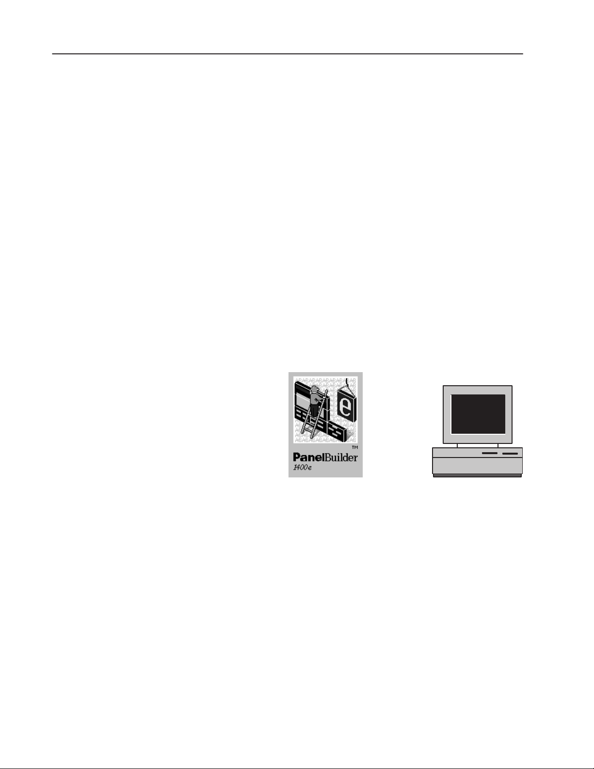
The following terminals will run PanelBuilder 1400e applications on
the Modbus network:
• PanelView 1000e terminals, Series A and above, running
Version 3 and later firmware
• PanelView 1400e terminals, Series A and above, running Version 3
and later firmware
Publication 2711E-6.12 – November 1997
Page 15

1–3Overview of PanelBuilder 1400e with Modbus Connectivity
"
Note: To communicate over a Modbus network, you must use a
PanelView 1000e or 1400e terminal that has been upgraded to
include a supported Modbus ISA communications card and Version 3
firmware with the Modbus communications driver. The PanelView
Serial Firmware Upgrade Utility must be used to install
Modbus-capable firmware in the terminal. For details about
installing and configuring a Modbus communications device (serial
card), and installing Modbus-capable firmware, see Chapter 7,
“Configuring the PanelView Terminal for Modbus
Communications.”
See the PanelView Enhanced Modbus Communications Option Kit
Release Note, Publication Number 2711E-6.12.1, for a list of
currently-supported Modbus communications cards.
The application screens created in PanelBuilder appear on the
PanelView terminal, replacing traditional hard-wired control panels.
They provide the physical interface between the controller and the
human operator.
Application screens contain objects that function like control panel
components. By using these objects to enter data or carry out
commands, the operator can monitor and control the process.
For information about installing and running PanelBuilder, see
Getting Started with PanelBuilder 1400e Configuration Software for
Windows, Publication Number 2711E-818. This manual also contains
a tutorial that guides you through enhancing an existing application
and running it on the PanelView terminal. A Modbus version of this
tutorial is also provided. The following .pvc files in the Tutorial
directory are the Modbus versions, which need to be enhanced:
• Mkctutor.pvc
• Mtctutor.pvc
The following .pvc files in the Tutorial directory are the Modbus
versions which have been enhanced:
• Mtutork.pvc
• Mtutort.pvc
The program for Modicon controllers is called “Tutorial,” and it is
located in the Tutorial directory.
Publication 2711E-6.12 – November 1997
Page 16
1–4 Overview of PanelBuilder 1400e with Modbus Connectivity
PanelView 1000e
Terminals
PanelView 1400e
Terminals
Touch Screen Terminals
Keypad Terminals
Publication 2711E-6.12 – November 1997
Page 17
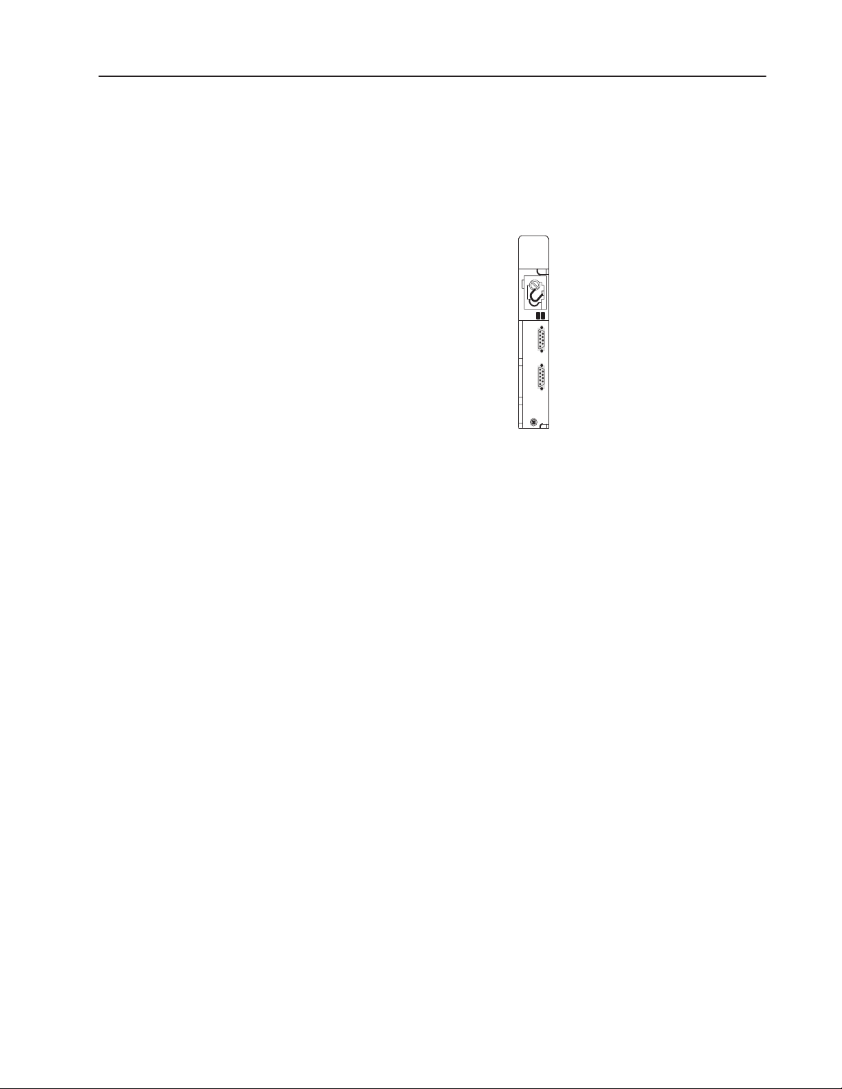
The Controller or Other Modbus Slave Device
When communicating over a Modbus network, the controller can
respond to queries from the PanelView terminal and other input or
output devices.
Modicon Controller
24762
1–5Overview of PanelBuilder 1400e with Modbus Connectivity
The PanelView terminal can be connected to a controller, or other
slave device on the Modbus network. The terminal can control and
monitor coils, inputs, and registers in these devices on the network.
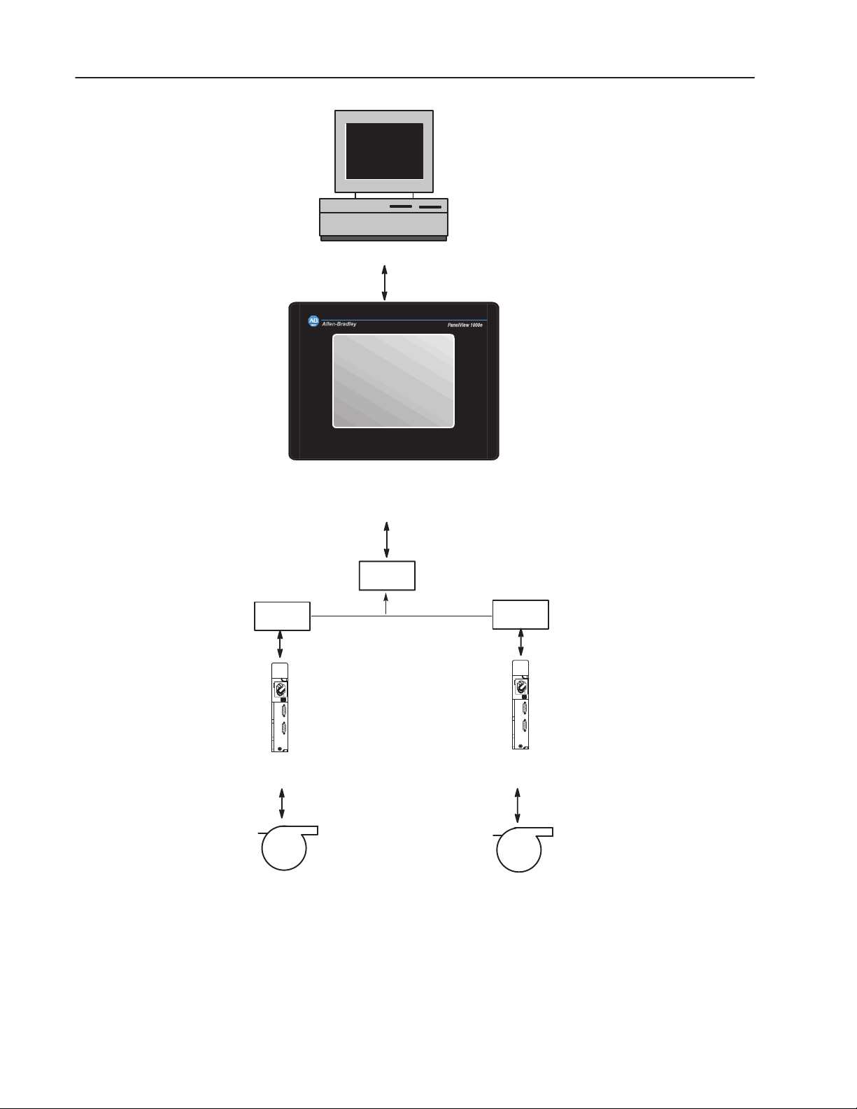
Understanding the Modbus Network
The following illustration shows the relationship between
PanelBuilder, the PanelView terminal, and the controller. In the
following illustration, the PanelView terminal is connected over
Modbus:
Publication 2711E-6.12 – November 1997
Page 18
1–6 Overview of PanelBuilder 1400e with Modbus Connectivity
The application is created in PanelBuilder on the
personal computer, and downloaded to the
PanelView operator terminal.
Development Computer
Serial Connection
PanelView
The PanelView terminal queries the
controller for process or machine
status information.
Operator input to the terminal is sent to
the controller. The controller uses this
information to control the machine or
process.
PanelView 1000e/1400e
Terminal
(Touch Screen)
Modem
Modem
Modbus
Programmable
Controller
Machine or
Process
Modem
Modbus
Programmable
Controller
Machine or
Process
24717
Publication 2711E-6.12 – November 1997
Page 19

Planning an Application for
Modbus
This chapter provides information about planning a Modbus
application, including defining nodes. For details about assigning
scan classes and assigning tags, refer to Chapter 2, “Planning
Applications,” in the PanelBuilder 1400e Configuration Software for
Windows User Manual, publication 2711E-819.
To plan a Modbus application, use the Modbus Communications
Worksheet and the Device Tags Worksheet (included in
Appendix A). They help you identify the devices with which your
application will be communicating and the device addresses relevant
to your application.
Use the information you record in these worksheets when assigning
tags to objects in the Tag Database editor and defining
communications using the Nodes editor and Scan Classes editor.
Defining Nodes and Scan Classes
Record node and scan class information on the Modbus
Communications worksheet to help keep track of terminal
communication information. Use these worksheets as a reference
when configuring nodes in the Nodes editor, and when assigning
scan classes to tags in the Tag Database editor. See Chapter 4,
“Defining Communications,” for details about working with these
editors.
Publication 2711E-6.12 – August 1997
Page 20
2–2 Planning an Application for Modbus
Defining the Nodes
A node is a Modbus slave device with which your application will be
communicating on a network. For each node, you must identify the
type of addressing the device uses (5- or 6-digit addressing), its
station address, and the timeout value. Each node must be given a
name to be used when defining tags.
Recording Node Information
"
"
For each node, fill in:
• Node Name: A user-defined node name. The name can be up to
40 characters long, and can include letters, numbers, dash ( – ),
and the underscore character ( _ ). You cannot use spaces.
Tip: Use a name that will help you to identify your Modbus
device when you are assigning tags later in your application. For
example, you could name your Modbus devices according to their
locations or the machine or part of the process they will be
controlling or monitoring.
Note: The node name “Unsolicited_Msgs is reserved for system
use in DH+ applications and cannot be assigned to a node defined
by the user. It allows the terminal to support unsolicited messages
to and from the controller. You cannot use a node with this name
in Modbus applications.
• Device: The type of controller or Modbus device. Specify a 5- or
6-digit addressable device.
• Channel: The Channel number is 1 by default. The application
network type determines this channel. You cannot change this
value.
• Station: The address that identifies the Modbus device’s location
on the network. Valid station addresses are between 1 and
247 (decimal).
Publication 2711E-6.12 – August 1997
Page 21

2–3Planning an Application for Modbus
About Scanning
"
Note: The PanelView terminal communicates with local Modbus
stations or with remote, bridged devices if a BM85 module is
connected and configured for the network.
• Enabled: If a node is enabled, the terminal will communicate
with the device at the node. If the node is not enabled, the
terminal will not communicate with the device. Instead, the
PanelView terminal stores values to be written to the device. This
allows system designers to test their applications without setting
up communications, and to avoid communication errors at the
terminal during testing.
• Timeout: The number of seconds the PanelView terminal should
wait before reporting a communication error. Three seconds is the
default when a new node is created.
Scanning works the same way for Modbus as it does for Data
Highway Plus. For information about scanning, refer to Chapter 2,
“Planning Applications,” in the PanelBuilder 1400e Configuration
Software for Windows User Manual, publication 2711E-819.
Recording Tag Information
"
"
Assigning tags to objects for the Modbus release of PanelBuilder is
similar to assigning tags to objects for DH+. You assign tags with the
Data Source type Device for Modbus applications. Analog, digital,
string, and block tags can all be used in Modbus applications. Where
differences exist between DH+ and Modbus applications, with
respect to assigning tags, they are highlighted in Chapter 6,
“Defining Tags.”
For generic information about assigning tags, see Chapter 2,
“Planning Applications,” in the PanelBuilder 1400e Configuration
Software for Windows User Manual, publication 2711E-819.
Note: You can use the Device Tags Worksheet to record tag
information for each dynamic object in a PanelBuilder application
for Modbus.
Note: For Modbus Device tags, the Tag Database editor supports the
full addressing syntax and range supported by the 5- and 6-digit
addressable devices.
Publication 2711E-6.12 – August 1997
Page 22
Basic Application Operations
This chapter supplements the information in the PanelBuilder 1400e
Configuration Software for Windows User Manual, publication
2711E-819. It describes only changes to basic application operations
for the Modbus network. For detailed information about other basic
application operations, consult Chapter 3, “Working with
Applications,” in the PanelBuilder 1400e Configuration Software for
Windows User Manual, publication 2711E-819.
This chapter describes how to create a new application, and some
changes to report options.
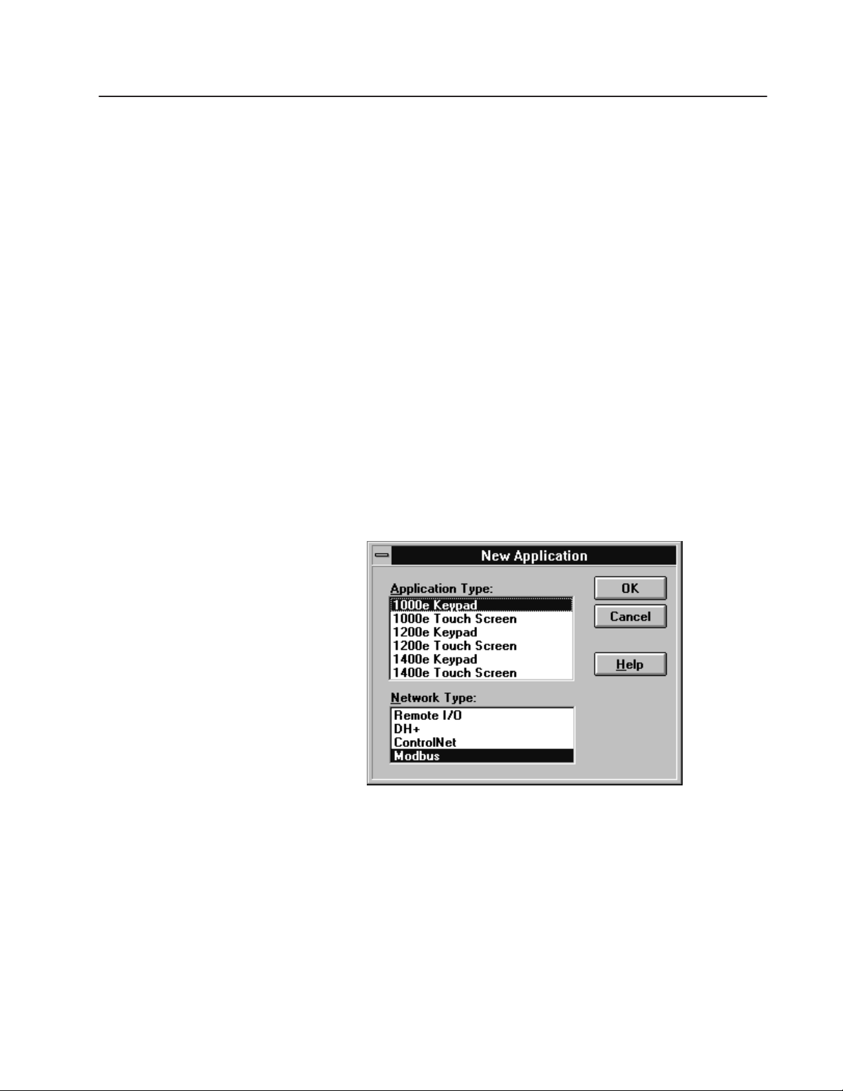
Creating a New Application
"
Note: PanelView 1200 and 1200e terminals do not support Modbus
communications.
To create a new application for Modbus:
1. Select the Application Type and highlight the Modbus option in
the Network Type list box.
Creating Reports
2. Choose OK.
Creating reports for a Modbus application is the same as for DH+
and Remote I/O applications. The only difference is the PLC
Communications report.
For detailed information about creating reports, see “Creating
Application Reports” in Chapter 3, “Working with Applications,” in
the PanelBuilder 1400e Configuration Software for Windows User
Manual, publication 2711E-819.
Publication 2711E-6.12 – November 1997
Page 23

3–2 Basic Application Operations
Additional Report on Options
You can generate a PLC Communications report for a Modbus
application that will display the following information:
• communications setup information
• node and scan class definitions
Publication 2711E-6.12 – November 1997
Page 24

Defining Communications
To define communications for a Modbus application, use these three
editors:
• Communication Setup editor—to specify the driver
information for connecting a PanelView terminal to a Modbus
device.
• Nodes editor—to identify the types and addresses of the
controllers the application will communicate with.
• Scan Classes editor—to define the speed at which tags used in
an application will be scanned for new values.
The other two editors in the PLC Communications folder, the RIO
Racks and RIO Block Transfer Files editors, are used exclusively for
defining Remote I/O communications.
Configuring Communications
The Configure Communication Setup dialog box has two tabs:
Terminal Communications and Network File Transfer.
In the Terminal Communications tab, you specify the driver
parameters for communicating with the Modbus network.
You cannot access the Network File Transfer tab from the
Communication Setup dialog box, because Network File Transfers
are not supported on Modbus networks.
T o open the Configure Communication Setup dialog box:
" Open the PLC Communications folder and choose
Communication Setup, or choose
from the toolbar.
Publication 2711E-6.12 – November 1997
Page 25

4–2 Defining Communications
Setting up Terminal Communications
In the Terminal Communications tab you can set the driver
parameters.
Setting the Driver Parameters
You must configure the driver parameters to correspond with the
communication settings of the device to which the PanelView
terminal is most immediately connected (whether a controller,
modem, BM85 module, or other Modbus device).
" Fill in the fields in the Driver section of the Configure
Communication Setup dialog box as follows:
Baud Rate
Specify the data-transfer rate between the PanelView terminal and
the device to which it is connected. The default setting is 9600.
Parity
Specify None, Even, or Odd for the type of error-checking to be
used. The default setting is Even.
Configuring Nodes
"
"
Flow Control
Specify Hardware or None to determine whether handshaking is
used for data transfer between the PanelView terminal and the
device to which it is connected. The default setting is None.
Note: Hardware flow control must be used with line drivers or
modems.
Stop Bits
Specify the number of stop bits used to signal the end of a data
packet transferred between the PanelView terminal and the device
to which it is connected. The default setting is 1.
Note: The number of data bits is fixed at 8.
A node is a device connected to the Modbus network. When you
configure nodes, you specify a name, device type, and station
address for each device the application will communicate with. A
device at a Modbus station is referred to throughout a PanelView
application by its node name.
You should already have determined the station address for each
node when you completed the Modbus Communications Worksheet.
If not, see Chapter 2, “Planning an Application for Modbus,” for
details about determining station addresses.
Publication 2711E-6.12 – November 1997
Page 26

4–3Defining Communications
Data Entry Form
Spreadsheet
Viewer
"
Note: A node configuration can be changed at any time during
application development. At application or screen validation, or
download, the nodes used by the tags in the application must be
defined. If you change the node’s device type, the tags that use this
node may have invalid addresses. If you change the node name, you
can automatically update your tags at the same time.
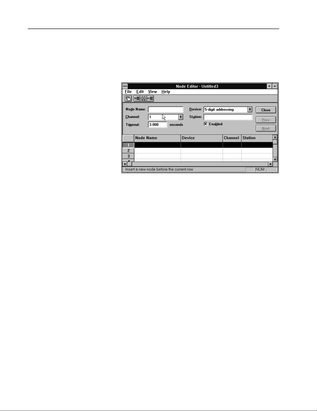
T o open the Node Editor:
" Open the PLC Communications folder and choose Nodes, or
choose
from the toolbar. The Node Editor opens.
"
The Node Editor has two parts: the data entry form on top where
you define the node, and the spreadsheet viewer on the bottom where
you see all the nodes and select one for editing.
T o configure the nodes:
1. Fill in the following information for each node. Use the
information you recorded in the Communications worksheet.
Node Name
Type a name of your choice up to 40 characters long. This name
represents a device on the network. The only valid characters for
a node name are a-z, A-Z, 0-9, – (dash), and _ (underscore). You
cannot use spaces. The name is not case-sensitive; your characters
will be displayed as you typed them.
Note: The node name “Unsolicited_Msgs is reserved for system
use in DH+ applications and cannot be assigned to a node defined
by the user. It allows the terminal to support unsolicited messages
to and from the controller. You cannot use a node with this name
in Modbus applications.
Publication 2711E-6.12 – November 1997
Page 27

4–4 Defining Communications
"
Tip: Use a name that will help you to identify your controllers
when you are assigning tags later in your application. For
example, you could name your controllers according to their
locations or according to the machine or part of the process they
will be controlling or monitoring.
Device
Select the type of device you are using from the drop-down list.
The type of device determines the addressing syntax and range
for all the tags with addresses on this node.
For Modbus applications, select 5-digit addressing or 6-digit
addressing, depending on the device you are using. See the user
manual for the device you are using, to determine whether to use
5- or 6-digit addressing.
Channel
The Channel number is 1 by default. The application network
type that you specified when you created your application refers
to this channel. You cannot change this value. This field
maintains compatibility with RSView and provides future
communication option expansion.
Station
Type the address of the device.
For Modbus applications, values are between 1 and
247 (decimal), whether the station is local or bridged.
Timeout
Type the number of seconds (0.100 to 6553.500) you want the
terminal to wait before reporting a communication error. The
default timeout period is 3 seconds.
Enabled
Normally nodes are enabled, allowing data collection. However,
while you are debugging your application or troubleshooting your
network, you can disable a node to prevent communication faults
or invalid data. Once the application file is downloaded and
running, any values normally sent to a disabled node will be
recorded in the terminal, but the actual device value will remain
unchanged.
To disable nodes, clear the Enabled check box.
Important: Make sure the nodes are enabled before you run
an application in an online environment.
2. When you’ve finished configuring nodes, choose Close.
Publication 2711E-6.12 – November 1997
Page 28

4–5Defining Communications
Configuring Scan Classes
Any tag that has Device as its data source must be assigned to a scan
class. At runtime, the PanelView terminal periodically updates its tag
information by scanning the device addresses. You determine how
often a tag value is updated by assigning the tag to a scan class that
you have configured in the Scan Classes editor. Make sure that tags
with rapidly changing device values are assigned to a fast scan rate,
while those that don’t change often are scanned less frequently. This
helps optimize traffic flow on the Modbus network. Proper use of
scan classes can reduce traffic on the Modbus network.
You should already have determined the rates for the scan classes
when you completed the Communications worksheet. If not, see
Chapter 2, “Planning Applications,” in the PanelBuilder 1400e
Configuration Software for Windows User Manual, for tips on
assigning foreground and background scan rates.
T o open the Scan Class Editor dialog box:
" Open the PLC Communications folder and choose Scan Classes,
or choose
from the toolbar.
The Scan Class Editor opens.
T o configure scan classes:
1. Fill in the following information for each scan class. Use the
information you recorded in the Communications worksheet.
Name—A Through K
You can keep the letter for the name of the scan class or you can
type a name up to 20 characters long. The name can have upper
and lower case letters, numbers, dashes, and underscores. You
cannot use spaces.
If you type a meaningful name, it will be easier to keep track of
what the scan classes represent. For example, you might name
one scan class TimeCritical, another SlowChanging, and so on.
Publication 2711E-6.12 – November 1997
Page 29

4–6 Defining Communications
Foreground and Background Period
The period specifies, in seconds, how often the device address
will be scanned. A foreground period applies to tags used on the
current screen, to the alarm and information window tags, and to
the tags under the PLC Controlled tab in the PLC I/O Control
dialog. The background scan period applies to tags used in all
other screens in the system. The valid range of values is 0 to
86,400 seconds (24 hours), with a 0.1 second resolution.
To specify a period, type a number. You can use fractions of a
second. For example, 0.6 means scan every six-tenths of a
second. Keep the background rate slow so as not to slow down
network traffic.
"
"
"
Tip: For more information about optimizing Modbus network
traffic, refer to your network user documentation. Also see
“Guidelines for Configuring Scan Classes” in Chapter 2,
“Planning Applications,” in the PanelBuilder 1400e
Configuration Software for Windows User Manual.
Note: If a tag is being used by both a foreground and background
component, the tag will be scanned at the foreground rate.
2. To save the information you’ve configured, choose OK.
Note: If you change the name of a scan class used by tags, you
have the option of automatically updating the tags with the new
name.
Publication 2711E-6.12 – November 1997
Page 30

Changing the Network Type
When you create an application, you specify the type of network it is
to run on, and set up the communication parameters accordingly. You
can change the network type of an existing application to run it on
another network. You do this using the Change Network Type dialog
box.
Converting from DH+ to Modbus
"
"
Note: When you change the network type to Remote I/O, all
communication specifications, including node definitions and scan
classes, will be lost. You will have to re-configure communications
for your application.
This chapter describes the following network switches:
• converting from DH+ to Modbus
• converting from Remote I/O to Modbus
• converting from ControlNet to Modbus
• converting from Modbus to DH+
• converting from Modbus to Remote I/O
• converting from Modbus to ControlNet
Note: You can either convert only the application, or the application
and its tags. In either case, you must edit tag addresses and node
definitions to make them valid for the new network type.
To change the network type from DH+ to Modbus:
Important: When you change an application from DH+ to Modbus,
you will have to add valid Modbus device tag
addresses.
1. Choose Change Network Type from the Tools menu.
2. In the Target Network field, choose Modbus.
3. Choose OK.
The following message will appear:
Publication 2711E-6.12 – August 1997
Page 31

5–2 Changing the Network Type
4. Choose Yes to change your DH+ application to Modbus. Choose
No if you do not wish to continue with the conversion.
"
Note: When converting to a Modbus application, the device type
defined for each node will be incompatible with the Modbus
network type. The following message will appear, prompting you
to convert the incompatible nodes.
5. Select Yes or No.
If you select Yes:
• the device type of any node will be changed to 5-digit
addressing
• the Unsolicited_Msgs node will be deleted
• any node with an invalid station number for the Modbus
network will be changed to have a station number of 1
• tag addresses will remain as DH+ addresses. You must change
these tag addresses to Modbus tag addresses.
Converting from Remote I/O to Modbus
If you select No, the network conversion will be cancelled.
To change the network type from Remote I/O to Modbus:
Important: When you change an application from Remote I/O to
Modbus, you will have to define the necessary Modbus
nodes and scan classes and add valid Modbus device tag
addresses.
1. Choose Change Network Type from the Tools menu.
2. In the Target Network field, choose Modbus.
3. To convert the tags in the application, select the Convert Tags
check box. If you don’t want to convert tags in the application,
clear the check from the Convert Tags check box.
• If you don’t convert the tags to Modbus format, the tags’ data
source remains Remote I/O. For any tags to be used in the
Modbus application, you will have to change the data source
to Device and give them valid Modbus addresses.
• If you do convert the tags to Modbus format, all the tags in the
database that are used by your application will be converted to
Device tags. Analog tags using the binary data type will be
switched to unsigned integer because binary is not supported
for Modbus applications.
Publication 2711E-6.12 – August 1997
Page 32

5–3Changing the Network Type
"
"
Note: If you convert shared tags, this may make them invalid for
the other applications that are using them. Unused tags are not
converted and remain as Remote I/O tags.
Note: If you convert an application from Remote I/O to Modbus,
or vice-versa, the tag addresses will be invalid for the network to
which you are converting. Change the tag addresses to match the
network type.
4. Specify a node name and scan class if required.
You can specify a node name and scan class when you do the
conversion, or you can leave them blank. If you enter a node
name and scan class, they will be used in all the tags that are
converted. In addition, the node and scan class will be created for
you with the default settings. You can change the settings to suit
your application later.
If you leave the Node Name and Scan Class fields blank, you will
have to create the nodes and scan classes that your tags will use,
then update each tag with the node and scan class names that you
have created. The converted tags will have a blank node and scan
class name.
Publication 2711E-6.12 – August 1997
Page 33

5–4 Changing the Network Type
5. Choose OK.
The following message will appear:
6. Choose Yes to confirm that you want to continue.
Converting from ControlNet to Modbus
To change the network type from ControlNet to Modbus:
Important: When you change an application from ControlNet to
Modbus, you will have to add valid Modbus device tag
addresses.
1. Choose Change Network Type from the Tools menu.
2. In the Target Network field, choose Modbus.
3. Choose OK.
The following message will appear:
Publication 2711E-6.12 – August 1997
Page 34

4. Choose Yes to change your ControlNet application to Modbus.
Choose No if you do not wish to continue with the conversion.
5–5Changing the Network Type
"
Note: When converting to a Modbus application, the device type
defined for each node will be incompatible with the Modbus
network type. The following message will appear, prompting you
to convert the incompatible nodes.
5. Select Yes or No.
If you select Yes:
• the device type of any node will be changed to 5-digit
addressing
• any node with an invalid station number for the Modbus
network will be changed to have a station number of 1
If you select No, the network conversion will be cancelled.
Converting from Modbus to DH+
To change the network type from Modbus to DH+:
Important: When you change an application from Modbus to DH+,
you will have to add valid DH+ device tag addresses.
1. Choose Change Network Type from the Tools menu.
2. In the Target Network field, choose DH+.
3. Choose OK.
The following message will appear:
Publication 2711E-6.12 – August 1997
Page 35

5–6 Changing the Network Type
4. Choose Yes to change your Modbus application to DH+. Choose
No if you do not wish to continue with the conversion.
"
Note: PanelBuilder checks that the station numbers and device types
of all Modbus nodes are valid when the network type is converted to
DH+. For example, station number 8 is an invalid octal number. The
following message will appear, prompting you to convert
incompatible nodes:
5. Select Yes or No.
If you select Yes:
• the device type of any node will be changed to PLC-5
(Enhanced)
• an Unsolicited_Msgs node will be added
If you select No, the network conversion will be cancelled.
Converting from Modbus to Remote I/O
"
If you change an application from Modbus to Remote I/O, you will
have to define the necessary Racks, specify the Block Transfer File
and Pass-Through control bytes, if needed, and add new tag
addresses, which are valid for Remote I/O.
T o change the network type from Modbus to Remote I/O:
1. Choose Change Network Type from the Tools menu.
2. In the Target Network field, choose Remote I/O.
3. To convert the tags in the application, select the Convert Tags
check box. If you don’t want to convert tags in the application,
clear the check from the Convert Tags check box.
• If you don’t convert the tags to Remote I/O format, the tags’
data source remains Device and the address is unchanged. You
will have to change the data source to Remote I/O manually
for any of these tags that you want to use, and give them each
a Remote I/O address.
• If you convert the tags to Remote I/O, the data source for all
the tags is changed to Remote I/O, but you will still have to
give them valid Remote I/O addresses manually.
Note: Converting tags that are shared may make them invalid for
the other applications that are using them. Unused tags that are
not converted will stay as Modbus tags.
Publication 2711E-6.12 – August 1997
Page 36

5–7Changing the Network Type
"
Note: If you convert an application from Modbus to Remote I/O,
or vice-versa, the tag addresses will be invalid for the network to
which you are converting. Change the tag addresses to match the
network type.
4. Choose OK.
The following message appears:
5. Choose Yes to confirm that you want to continue.
6. Once you have changed the network type you will have to
configure the controller type, rack assignments, block transfer
files, and Pass-Through control byte, if needed, in the Rack and
Block Transfer File editors.
Converting from Modbus to ControlNet
To change the network type from Modbus to ControlNet:
Important: When you change an application from Modbus to
ControlNet, you will have to add valid ControlNet
device tag addresses.
1. Choose Change Network Type from the Tools menu.
2. In the Target Network field, choose ControlNet.
3. Choose OK.
The following message will appear:
Publication 2711E-6.12 – August 1997
Page 37

5–8 Changing the Network Type
4. Choose Yes to change your Modbus application to ControlNet.
Choose No if you do not wish to continue with the conversion.
"
Note: If a Modbus node is defined as station 1, or station 64
through 247 (inclusive), it will be invalid for a ControlNet
application. The following message will appear, prompting you to
convert the station number. The device types defined for all nodes
will also have to be changed when the application is converted to
ControlNet.
5. Select Yes or No.
If you select Yes:
• the device type of any node will be changed to
PLC5-Enhanced
• any node with an invalid station number for the ControlNet
network will be changed to have a station number of 2
If you select No, the network conversion will be cancelled.
Publication 2711E-6.12 – August 1997
Page 38

Defining Tags
Use tags to name controller addresses for easy reference. For more
information about tags and their role, the tag database editor, and
how to create tags, see Chapter 6, “Defining Tags,” in the
PanelBuilder 1400e Configuration Software for Windows User
Manual.
Tag Types
PanelBuilder uses the following types of tags:
This tag
type:
Analog
Digital 0 or 1
String ASCII string, series of characters or whole words (maximum of 82
Block A contiguous bit stream of up to 1024 bits. A block tag is used strictly for
Stores this type of data:
Range of values (depends on the data type (integer or floating point)
selected)
These tags can represent complex states such as temperature or the
position of rotary controls.
These tags can represent devices that can only be on (1) or off (0), such
as push buttons.
characters)
These tags are used only when defining ASCII Input and ASCII Display
objects, and for sending alarm messages to the controller.
defining the Alarm Triggers tag and Acknowledge to PLC tag when
multiple simultaneous alarms need to be monitored. Use Block Tags when
using bit-triggered alarms. PanelBuilder Version 3 supports Device block
tags as well as Remote I/O block tags.
Read and Write Tags
"
At runtime, PanelBuilder objects and control functions can read from
or write to controller addresses assigned to any of the tag types. The
terms read tag and write tag will sometimes be used. A read tag is a
tag with a controller address that only needs to be read by
PanelBuilder objects and functions. A write tag is a tag with a
controller address that can be written to by PanelBuilder objects and
functions.
Note: When connected to a Modbus network, the PanelView
terminal is the only device initiating reads and writes (master
device). All other devices are slaves.
Publication 2711E-6.12 – August 1997
Page 39

6–2 Defining Tags
Data Sources
"
Note: You can use Expressions to perform calculations, logical, and
conditional operations to manipulate the values of tags. See
Chapter 7, “Creating Expressions” in the PanelBuilder 1400e
Configuration Software for Windows User Manual.
The other two data sources you can see in the Tag Database editor,
Memory and DDE, are used only by RSView.
Device
When you create tags for a Modbus application, select Device as the
data source. This means that the data comes from a specific memory
location in a controller that is connected to the Modbus network.
For each tag you must specify a node name, a scan class, and the
physical address within the controller that the tag references. The
node name refers to the controller’s location on the Modbus network;
the scan class determines how often the terminal checks the value at
this address. See Chapter 2, “Planning Applications,” in the
PanelBuilder 1400e Configuration Software for Windows User
Manual, for details on configuring nodes and scan classes. Appendix
A of this manual contains a worksheet to help you plan scan classes.
Configuring Tag Type
"
"
This section describes how to fill in the fields for analog, digital,
string, and block tag types. Use the information you entered on the
Device Tags worksheet described in Chapter 2, “Planning
Applications,” in the PanelBuilder 1400e Configuration Software for
Windows User Manual. The Device Tags worksheet is included in
Appendix A of this manual.
Note: The Log Data and Alarm check boxes in the Tag Database
editor are present to maintain compatibility with RSView databases.
You cannot use them in PanelBuilder.
Tip: For information about assigning tag addresses that optimize
network traffic, see “Guidelines For Organizing Tags to Optimize
Network Performance” in Chapter 2, “Planning Applications,” in the
PanelBuilder Configuration Software for Windows User Manual.
Publication 2711E-6.12 – August 1997
Page 40

6–3Defining Tags
Configuring an Analog Tag
1. If the tag is part of a folder, select that folder in the folder
hierarchy. The folder name appears in the Name field and is the
first part of the tag name.
2. Type a tag name. If the tag is part of a folder, type the name after
the backslash (\).
3. For Type, select Analog.
4. Fill in the fields as outlined below:
Security
This field is reserved for RSView databases. You cannot enter
anything in the Security field.
Description
Type a description of this tag up to 128 characters long.
Minimum and Maximum
These fields are reserved for RSView databases. You cannot enter
anything in the Minimum and Maximum fields.
Publication 2711E-6.12 – August 1997
Page 41

6–4 Defining Tags
Scale and Offset
Type a number. For the scale, do not use 0.
Scale and offset together transform raw controller data into
meaningful units for the operator. At runtime, all data read from
the controller into an analog tag will be scaled using the formula:
y = (mx) + b
where m = scale
x = raw PLC data
b = offset
y = scaled value
The terminal displays the scaled value. When data is written to
the controller using an analog tag, the value will be inversely
scaled using the formula:
ǒ
Ǔ
*
+
This converts the value back to raw controller data before it is
written to the PLC. With Scale = 1 and Offset = 0 (the default
values for a new analog tag), the controller data is not changed.
Important: A fractional scale or offset value will result in a
floating point scaled value. This will be true
regardless of the tag’s data type. Extensive use
of floating point values can slow a terminal’s
performance.
"
Important: If the descaled value to be written to the tag
address is a fraction, but the tag is not
configured to deal with floating point data (i.e.,
Float data type or Default data type with a tag
address in the Float section of the controller),
the value will be truncated to the nearest whole
number before it is written to the tag address.
Note: You can also use expressions to perform calculations on
the values of analog and digital tags that read information from
the controller. See Chapter 7, “Creating Expressions,” in the
PanelBuilder 1400e Configuration Software for Windows User
Manual.
Units
This field is reserved for RSView databases. You cannot enter
anything in the Units field.
Publication 2711E-6.12 – August 1997
Page 42

6–5Defining Tags
Data Type
Select the data type that matches the format of the data stored in
the controller. The default entry in the data type field is Default.
In Modbus applications, the Default data type is Unsigned Integer
with an address length of 16 bits. Unless special data is expected,
Default should be acceptable.
The following data types are supported for Analog tags in a
Modbus application:
Data Type Description
Default
Byte Unsigned 8-bit value. Uses the lower 8 bits of the 16-bit
Unsigned Integer Unsigned 16-bit value.
Integer Signed 16-bit value.
Long Integer Signed 32-bit value.
Bit Position Value range from 0 to 16. Address length fixed at 16 bits.
1 BCD Value range 0 to 9. Uses lower 4 bits of 16-bit address.
2 BCD Value range 0 to 99. Uses lower 8 bits of 16-bit address.
3 BCD Value range 0 to 999. Uses lower 12 bits of 16-bit address.
4 BCD Value range 0 to 9999.
Floating Point Single-precision (32-bit) floating point value. The range of data
BIN 3 Value range 0 to 999. Uses a 16-bit address.
BIN 4 Value range 0 to 9999. Uses a 16-bit address.
BIN 6 Value range 0 to 999999. Uses a 32-bit address.
BIN 8 Value range 0 to 99999999. Uses a 32-bit address.
Unsigned 16-bit value.
address.
values is –3.402823E +38 to –1.175494E –37, 0, and
+1.175494E –37 to +3.402823E +38.
"
Initial Value
This is the default value of the tag at the terminal. When a tag is
used with a PanelBuilder input object or function, this initial
value, after descaling, is written to the controller when the
application first executes.
For a PanelBuilder object with an initial state and a main control
tag, the object’s initial state value supersedes the tag’s initial
value, so that the initial state value is written to the controller
instead of the tag’s initial value. On application upload, the
object’s initial state value is used as the tag’s initial value.
Note: For the PanelView terminal to write default values to the
controller, you must choose No for “Use Default Operation,” on
the terminal’s Application Startup screen, and you must cycle
power to the terminal. Default values are written to the controller
whenever you subsequently cycle power to the terminal.
Publication 2711E-6.12 – August 1997
Page 43

6–6 Defining Tags
5. To fill in the fields for data source, see Specifying a Data
Source” later in this chapter.
Modbus Address Space
Modbus devices can contain four distinct address spaces. Two spaces
are reserved for Coil data and two are reserved for Register data. The
PanelView terminal can only write to one of the two Coil address
spaces but can read from both spaces. The same is true for the two
Register address spaces.
Modicon controllers store read and write address spaces in the
following data table locations:
Reference Address Type Data Access Description
0
1 Discrete Input bit read-only Use to drive contacts in the logic
3 Input Register word
Discrete
Output or Coil
(internal)
bit read or
write
read-only
Use to drive a real output through an
output module or to set one or more
internal coils. A coil can be used to
drive multiple contacts.
program. The input state is controlled
by an input module.
Holds numeric inputs from an external
source (for example, a thumb wheel
entry, an analog signal or data from a
high speed counter). A 3x register can
also store 16 contiguous discrete
signals that are entered into the
register in either binary or binary coded
decimal (BCD) formats.
Publication 2711E-6.12 – August 1997
Page 44

Reference DescriptionData AccessAddress Type
4
6 Extended
Output Holding
Register
Memory
Register
word read and
write
access
through Logic
Program only
Use to store numerical (decimal or
binary) information or to send the
information to an output module.
Use to store information in an extended
memory area. Only available in
controllers with 24 bit CPUs that
support extended memory such as the
984B, E984-785, and Quantum series
of controllers.
Addressing Syntax
For analog tags, the addressing syntax is as follows:
Addressing Syntax for Devices Using 5-digit Addressing:
Reference Operations Addressing Syntax
0
1 bit
3 word
4 word
bit
read and write
read only
read only
read and write
0bbbb where
bbbb = bit 0001 to 9999 (decimal)
and bbbb must align on word boundaries
(e.g. 00001, 00017, 00033)
1bbbb where
bbbb = bit 0001 to 9999 (decimal)
and bbbb must align on word boundaries
e.g. 00001, 00017, 00033)
3wwww where
wwww = word offset 0001 to 9999 (decimal).
Bit offsets are not supported.
4wwww where
wwww = word offset 0001 to 9999 (decimal).
Bit offsets are not supported.
6–7Defining Tags
Addressing Syntax for Devices Using 6-digit Addressing:
Reference Operations Addressing Syntax
3
4 word
word
read only
read and write
3wwwww where
wwwww = word offset 00001 to 65535 (decimal).
Bit offsets are not supported.
4wwwww where
wwwww = word offset 00001 to 65535 (decimal).
Bit offsets are not supported.
Publication 2711E-6.12 – August 1997
Page 45

6–8 Defining Tags
Important: Because analog tags with References 1 or 3 are read
only, they can only be assigned to display objects (e.g.
Numeric Data Display). An error will be generated
when you validate the application, if a tag with
Reference 1 or 3 has been assigned to an input object.
For more information about types of objects, see
Chapter 9, “Creating Objects,” in the PanelBuilder
1400e Configuration Software for Windows User
Manual, Publication Number 2711E-819.
Configuring a Digital Tag
A digital tag has two possible values at runtime: 0 or 1. Use a digital
tag wherever a toggle or Boolean function is needed.
1. If the tag is part of a folder, select the folder in the folder
hierarchy. The folder name appears in the Name field and is the
first part of the tag name.
2. Type a tag name. If the tag is part of a folder, type the name after
the backslash (\).
3. For Type, select Digital.
Publication 2711E-6.12 – August 1997
Page 46

4. Fill in the fields as outlined below:
Security
This field is reserved for RSView databases. You cannot enter
anything in the Security field.
Description
Type a description of this tag up to 128 characters long.
Off Label and On Label
These fields are reserved for RSView databases. You cannot enter
anything in them.
Initial Value
Enter an initial value of 0 or 1 for the digital tag. When a tag is
used with a PanelBuilder input object or function, this initial
value is written to the controller when the application first
executes.
For a PanelBuilder object with an initial state and a main control
tag, the object’s initial state value supersedes the tag’s initial
value, so that the initial state value is written to the controller
instead of the tag’s initial value. On application upload, the
object’s initial state value is used as the tag’s initial value.
6–9Defining Tags
"
Note: For the PanelView terminal to write default values to the
controller, you must choose No for “Use Default Operation,” on
the terminal’s Application Startup screen, and you must cycle
power to the terminal. Default values are written to the controller
whenever you subsequently cycle power to the terminal.
5. To fill in the fields for data source, see Specifying a Data
Source” later in this chapter.
Addressing Syntax
For digital tags, the addressing syntax is as follows:
Addressing Syntax for Devices Using 5-digit Addressing:
Reference Operations Addressing Syntax
0
1 bit
3 word
4 word
bit
read and write
read only
read only
read only
0bbbb where
bbbb = bit 0001 to 9999 (decimal)
1bbbb where
bbbb = bit 0001 to 9999 (decimal)
3wwww/bb where
wwww = word offset 0001 to 9999 (decimal)
/bb = bit offset in word 01 to 16 (decimal)
4wwww/bb where
wwww = word offset 0001 to 9999 (decimal)
/bb = bit offset in word 01 to 16 (decimal)
Publication 2711E-6.12 – August 1997
Page 47

6–10 Defining Tags
Addressing Syntax for Devices Using 6-digit Addressing:
Reference Operations Addressing Syntax
3
4 word
word
read only
read only
3wwwww/bb where
wwwww = word offset 00001 to 65535 (decimal)
/bb = bit offset in word 01 to 16 (decimal)
4wwwww/bb where
wwwww = word offset 00001 to 65535 (decimal)
/bb = bit offset in word 01 to 16 (decimal)
"
Note: Digital tags support only bit addresses.
Important: Because digital tags with References 1, 3, or 4 are
read-only, they can only be assigned to display objects
(e.g. Numeric Data Display). An error will be generated
when you validate the application if a tag with
Reference 1, 3, or 4 has been assigned to an input
object. For more information about types of objects, see
Chapter 9, “Creating Objects,” in the PanelBuilder
1400e Configuration Software for Windows User
Manual, Publication Number 2711E-819.
Configuring a String Tag
1. If the tag is part of a folder, select the folder in the folder
hierarchy. The folder name appears in the Name field and is the
first part of the tag name.
Publication 2711E-6.12 – August 1997
Page 48

"
6–11Defining Tags
2. Type a tag name. If the tag is part of a folder, type the name after
the backslash (\).
3. For Type, select String.
4. Fill in the fields as outlined below:
Security
This field is reserved for RSView databases. You cannot enter
anything in the Security field.
Description
Type a description of this tag up to 128 characters long.
Length
Type a number between 1 and 82 to specify the length of the
string tag in bytes. The length must be a multiple of 2. Tags using
References 0 and 1 must align on word boundaries.
Initial Value
Enter an initial value for the tag. When a tag is used with a
PanelBuilder input object or function, this initial value is written
to the controller when the application first executes.
Note: For the PanelView terminal to write default values to the
controller, you must choose No for “Use Default Operation,” on
the terminal’s Application Startup screen, and you must cycle
power to the terminal. Default values are written to the controller
whenever you subsequently cycle power to the terminal.
"
Note: There can be no more than 720 string tags in an
application.
5. To fill in the fields for data source, see Specifying a Data
Source” later in this chapter.
Publication 2711E-6.12 – August 1997
Page 49

6–12 Defining Tags
Addressing Syntax
For string tags, the addressing syntax is as follows:
Addressing Syntax for Devices Using 5-digit Addressing:
Reference Operations Addressing Syntax
0
1 bit
3 word
4 word
bit
read and write
read only
read only
read and write
0bbbb where
bbbb = bit 0001 to 9999 (decimal)
and bbbb must align on word boundaries
(e.g. 00001, 00017, 00033)
1bbbb where
bbbb = bit 0001 to 9999 (decimal)
and bbbb must align on word boundaries
(e.g. 00001, 00017, 00033)
3wwww where
wwww = word offset 0001 to 9999 (decimal).
Bit offsets are not supported.
4wwww where
wwww = word offset 0001 to 9999 (decimal).
Bit offsets are not supported.
Addressing Syntax for Devices Using 6-digit Addressing:
Reference Operations Addressing Syntax
3
4 word
word
read only
read and write
3wwwww where
wwwww = word offset 00001 to 65535 (decimal).
Bit offsets are not supported.
4wwwww where
wwwww = word offset 00001 to 65535 (decimal).
Bit offsets are not supported.
Important: Because string tags with References 1 or 3 are
read-only, they can only be assigned to display objects
(e.g. Numeric Data Display). An error will be generated
when you validate the application if a tag with
Reference 1 or 3 has been assigned to an input object.
For more information about types of objects, see
Chapter 9, “Creating Objects,” in the PanelBuilder
1400e Configuration Software for Windows User
Manual, Publication Number 2711E-819.
Publication 2711E-6.12 – August 1997
Page 50

6–13Defining Tags
Configuring a Block Tag
Use the following procedure to configure a block tag:
Important: Block tags are used only for the Alarm Control and the
Alarm Acknowledge Value control when multiple,
simultaneous alarms need to be monitored. For more
information, see Chapter 11, “Configuring Alarms,” in
the PanelBuilder 1400e Configuration Software for
Windows User Manual.
1. If the tag is part of a folder, select the folder in the folder
hierarchy. The folder name appears in the Name field and is the
first part of the tag name.
2. Type a tag name. If the tag is part of a folder, type the name after
the backslash (\).
3. For Type, select Block.
Publication 2711E-6.12 – August 1997
Page 51

6–14 Defining Tags
"
4. Fill in the fields as outlined below:
Security
This field is reserved for RSView databases. You cannot enter
anything in the Security field.
Description
Type a description of this tag up to 128 characters long.
Number of Bits
Enter a number from 1 to 1024 to define the length of the block.
The tag’s address must start on a word boundary, e.g. 00001,
00017, 00033, and the number of bits must be a multiple of 16.
Initial Value
Enter a 1 or 0 to initialize the entire block to 1 or 0 (i.e., all bits 1
or all bits 0). When a tag is used with a PanelBuilder input object
or function, this initial value is written to the controller when the
application first executes.
Note: For the PanelView terminal to write default values to the
controller, you must choose No for “Use Default Operation,” on
the terminal’s Application Startup screen, and you must cycle
power to the terminal. Default values are written to the controller
whenever you subsequently cycle power to the terminal.
5. To fill in the fields for data source, see Specifying a Data
Source,” next.
Addressing Syntax
For block tags, the addressing syntax is as follows:
Addressing Syntax for Devices Using 5-digit Addressing:
Reference Operations Addressing Syntax
0
1 bit
3 word
4
bit
read and write
read-only
read-only
word
read and write
0bbbb where
bbbb = bit 0001 to 9999 (decimal)
and bbbb must align on word boundaries
(e.g. 00001, 00017, 00033)
1bbbb where
bbbb = bit 0001 to 9999 (decimal)
and bbbb must align on word boundaries
(e.g. 00001, 00017, 00033)
3wwww where
wwww = word offset 0001 to 9999 (decimal).
No bit offsets are supported.
4wwww where
wwww = word offset 0001 to 9999 (decimal).
No bit offsets are supported.
Publication 2711E-6.12 – August 1997
Page 52

Addressing Syntax for Devices Using 6-digit Addressing:
Reference Operations Addressing Syntax
3
4 word
word
read-only
read and write
3wwwww where
wwwww = word offset 00001 to 65535 (decimal).
No bit offsets are supported.
4wwwww where
wwwww = word offset 00001 to 65535 (decimal).
No bit offsets are supported.
Important: Because block tags with References 1 or 3 are read
only, they can only be assigned to display objects (e.g.
Numeric Data Display). An error will be generated
when you validate the application if a tag with
Reference 1 or 3 has been assigned to an input object.
For more information about types of objects, see
Chapter 9, “Creating Objects,” in the PanelBuilder
1400e Configuration Software for Windows User
Manual, Publication Number 2711E-819.
6–15Defining Tags
Specifying a Data Source
"
"
The data source determines where a tag’s data comes from. Tags
defined for a Modbus application must specify the Device data
source.
Note: DDE and Memory data sources are only used by RSView.
For a Modbus application, the tag’s reference determines whether it
is a read or a write tag:
Reference Number Operation
0
1 read only
3 read only
4 read and write
read and write
Note: The exception is for digital tags, for which Reference 4 is
read only.
Important: Because tags with References 1 or 3 are read-only, they
can only be assigned to display objects (e.g. Numeric
Data Display). An error will be generated when you
validate the application if a tag with Reference 1 or 3
has been assigned to an input object. For more
information about types of objects, see Chapter 9,
“Creating Objects,” in the PanelBuilder 1400e
Configuration Software for Windows User Manual,
Publication Number 2711E-819.
Publication 2711E-6.12 – August 1997
Page 53

6–16 Defining Tags
Important: For Modbus analog tags, the entire controller data file
element assigned to the tag’s address is used in
determining the tag’s value. This is true regardless of
the tag’s data type. For example, a Byte data type
assigned with the address 30001 will still look at the
entire 16 bits of the integer element, even though the
tag is interested only in the lower 8 bits. The
controller’s logic must ensure that the unused bits are 0,
to prevent invalid or out of range data from being read
from the address.
Device Data Source
A tag with Device as its data source reads or writes its data to or
from a device on the Modbus network. If you have not configured
the node and scan class for the tag, you can configure them from the
Tag Database editor while you are defining a tag, or you can
configure them after you have finished creating tags. If you want to
define them after the tag is created, make sure any one of the node,
scan class, or address fields is blank so that Accept will not validate
and expect a valid tag record complete with supporting node and
scan class definitions.
Validation
Tags are validated when you choose Accept, and any errors must be
corrected before the tag definition will be saved. Validation ensures
that any node and scan class definitions needed by the tag exist.
Specifying Device as the Data Source
Use the information on the Device Tags worksheets to fill in the tag
addresses.
1. Choose Device.
Publication 2711E-6.12 – August 1997
Page 54

6–17Defining Tags
2. The node is the controller that this tag addresses. In the Node
Name field, do one of the following:
• type a node name.
• double-click in the Node Name field to open the Add Node or
Edit Node dialog box. If the field is empty you can create a
new node definition; if the field contains the name of an
existing node, you can edit that node’s definition.
• choose to open a selection list and select a node name.
For information about configuring nodes see Chapter 4, Defining
Communications.
3. Select a scan class.
For information about configuring scan classes, see Chapter 2,
“Planning Applications” in the PanelBuilder 1400e Configuration
Software for Windows User Manual.
4. In the Address field, type the tag’s physical memory location in
the PLC.
Tag Database Import and Export
"
Note: For Device block tags, the address is the starting address
for the block. For References 3 and 4, the block must be element
aligned. For References 0 and 1, the block must be word aligned.
The address cannot cross the controller’s reference boundaries.
The address syntax depends on the controller’s addressing
convention. For detailed information about address syntax for
each tag type, see the sections on each of the tag types earlier in
this chapter.
You can import or export a tag database, to reduce re-keying and
errors when tags are converted between systems.
Database Formats Supported
When you import a database, the tag definitions are copied into your
current database. If the database is private, it remains private. A
shared database remains shared.
The following file formats are supported:
• PanelBuilder .csv—exported by RSView and PanelBuilder. You
can also create a database in Microsoft Excel, save it as a .csv
file, and then import it into PanelBuilder.
• A.I. Series .csv—exported by the A.I. Series software
• Logic 5 .csv—exported from a Logic 5 database (see note below)
• PanelBuilder Tag Database—an independent tag database
Publication 2711E-6.12 – August 1997
Page 55

6–18 Defining Tags
• Taylor ProWORXPLUS database
• MODSOFT database in flat text format
"
"
Note: To import information from an A.I. Series database, you must
first export the database in text format using the A.I. software.
PanelBuilder imports this text file. To import a Logic 5 database,
export it to a text file and import this into A.I. software. You can then
export the text file from A.I. as you would any other A.I. database,
and import it to PanelBuilder. You can also import a
PanelBuilder 900 database by exporting it in an A.I. text format, and
then importing this into PanelBuilder as an A.I. database.
You can export a tag database created in PanelBuilder to any of the
following formats:
• PanelBuilder .csv file (comma separated variable) that can be
used by third-party software such as Microsoft Excel.
• Taylor ProWORXPLUS database
• MODSOFT database in flat text format
Tip: An exported PanelBuilder 1400e database can also be imported
back into the application. This means you can use the Database
Export feature to back up or update the database.
T o import a database or .csv tag file:
1. Open the application you want to import a tag database to.
2. Select Import/Export from the Database menu.
3. From the list that is displayed, choose the type of database you
want to import.
Publication 2711E-6.12 – August 1997
Page 56

6–19Defining Tags
4. To make the import faster, select the Skip Existing Tags button.
To update existing tags from the tags being imported, select the
Update Existing Tags button.
5. Select Next.
6. If you are importing a tag database, as opposed to a .csv format
file, specify a Tag Database Data Source, or select the Down
Arrow to display the list of sources, and choose one from it.
If you are importing a .csv tag file or a text database, specify the
file or choose the ... button and select the file from the Select File
dialog box.
Publication 2711E-6.12 – August 1997
Page 57

6–20 Defining Tags
7. Select Next.
If you are importing a Taylor ProWORXPLUS database, you can
choose to include the symbol file (*.fis). This file contains only
the tag addresses, and their corresponding names. The symbol file
must have the same name as the database file, and must be
located in the same directory.
8. Select Next.
If you are importing a Taylor ProWORXPLUS database, ensure
the tags are imported as Device Tags, since Remote I/O tags are
not supported for Modbus applications. You can specify a default
node name and scan class for the tags you are importing.
Publication 2711E-6.12 – August 1997
Page 58

9. When you choose Done, a summary dialog is displayed.
It contains the following fields:
• Source—this is the file from which you are importing tags.
• Intermediate Files—the PanelBuilder .csv file is the file
which is imported into PanelBuilder as a result of the tag
conversions from the source database. The Tag Name
Conversion File shows how tag names were converted from
the Taylor or MODSOFT symbols to PanelBuilder. Check this
file if you want to check tag name conversions. This file does
not exist for database formats other than Taylor or
MODSOFT.
• Destination—this is the name of the current PanelBuilder
application’s database.
• Number of Lines in Intermediate PanelBuilder CSV
File—the number of tags imported.
6–21Defining Tags
Once the import is complete, a summary window is displayed.
Errors, if any, and their locations in the Tag Import file are
displayed. To correct the errors, edit the Tag Import file directly.
Publication 2711E-6.12 – August 1997
Page 59

6–22 Defining Tags
"
"
"
Note: Choose Print from the File menu, to print the contents of
the Database Import information window. The log file is also
saved at the location and file name specified on the status bar.
Note: Choose Exit from the File menu to close this window and
complete the import. The Database menu item on the Application
Window menu bar remains grayed, and cannot be selected, until
the Database Import information window is closed.
Note: If you import a database that contains the Unsolicited_Msgs
node into a Modbus application, you must delete the node before you
download the application. Otherwise, PanelBuilder will report a
validation error.
T o export a database:
1. Open the application you want to export a tag database from.
2. Select Import/Export from the Database menu.
3. From the list that is displayed, choose the type of file or database
you want to export to and choose Next.
A default destination file name (pvtags.csv) and path are
displayed.
If you are exporting to a Taylor ProWORXPLUS database, you
can choose to include the symbol file (*.fis). This file contains
only the tag addresses, their corresponding names, and their
descriptions.
4. Choose Finish to complete the export, or type a new destination
file name and/or path, and then choose Finish.
Publication 2711E-6.12 – August 1997
"
Note: When exporting a PanelBuilder database in MODSOFT
format, tag addresses for 5-digit addressable devices are
converted to 6-digit addresses. A zero is added after the reference
number to convert the tag to 6-digit addressing.
Page 60

6–23Defining Tags
"
"
Note: When exporting a PanelBuilder database in Taylor
ProWORXPLUS or MODSOFT format, tags with duplicate
addresses are not exported. Only the first instance of the tag
address is exported.
Note: For Taylor ProWORXPLUS databases, lines containing
short comments, long comments or page titles are not imported or
exported.
Important: When exporting a PanelBuilder database to
Taylor ProWORXPLUS, a ‘Z’ is added to any
tag name that begins with a number. Tag names
longer than 32 characters are truncated, and
modified, if necessary, to prevent duplication.
See the symb_tag.csv file in the directory in
which PanelBuilder is installed, to check tag
name conversions.
CSV File Column Ordering
When you convert a PanelBuilder database to a comma separated
variable (.csv) file, or when you create a spreadsheet in third-party
software, it should consist of the following columns:
Column Description
A Tag Type
B Tag Name Any legal tag name
C Tag Description Text describing the tag
D Read Only T or F: use F (Specifies whether the tag is editable in the database.)
E Data Source D, E, R, I, M, S (Device, DDE, Remote, I/O, Memory, System)
F Security Code * (asterisk) or letters A-P: use * (A-P used by RSView only)
G Alarmed T or F (not yet supported): use F
H Data Logged T or F (not yet supported): use F
I Native Type D, U, I, L, F, B, P, N, W, X, Y, Z and 1-8 (Default, Unsigned Integer,
J Value Type L or F (Use F if scale offset or initial analog value uses decimal digits,
K Min Analog Minimum analog value: use 0
L Max Analog Maximum analog value: use 100
M Initial Analog Initial analog value (analog tag)
N Scale Scale multiplier (val = Scale(X) + Offset) (analog tag)
O Offset Offset (analog tag)
P Deadband Deadband (Unused): use 0
Q Units Units label: use blank
R Off Label Digital Digital off label: use blank
A, D, S, T, B, or F (Analog, Digital, String, Structure, Block, Folder)
Integer, Long, Floating Point, Byte, Bit Position, Binary, BIN3, BIN4,
BIN6, BIN8, and 1BCD-8BCD)
otherwise use L)
Publication 2711E-6.12 – August 1997
Page 61

6–24 Defining Tags
Column Description
S On Label Digital
T Initial Digital Initial digital value (must be either the on or off label): use 0 or 1 (digi-
U Length String String length (string tag)
V Initial String Initial string value (string tag)
W Node Name Node name (device tag)
X Address Programmable logic controller address (device tag)
Y Scan class Scan class name: use A–K or custom names (device tag)
Z DDE Applica-
tion
AA DDE Topic DDE topic name: use blank
AB DDE Item DDE item name: use blank
AC System
Source
AD System
Source Index
AE RIO Address Remote I/O address (Remote I/O tags)
AF Element Size
Block
AG Number
Elements Block
AH Initial Block Initial value of a block tag (0 or 1)
Digital on label: use blank
tal tag)
DDE application name: use blank
System data source name: leave blank
System data source index: leave blank
Use B (block tag)
Number of bits in the block tag
Creating a New Tag Database
The New Database command on the Database menu creates a new,
empty tag database for the application. When you use this, all the
tags in the current database, whether it is private or shared, are
deleted. If the application has a shared database that no longer exists,
a new shared database is created.
Publication 2711E-6.12 – August 1997
Page 62

Configuring the PanelView
Terminal for Modbus
Communications
This chapter is intended to supplement the information in the
PanelView 1000e, 1200e, and 1400e Operator Terminals User
Manual, Publication Number 2711E-821. Please refer to it for
information about the PanelView terminal’s power-up and online
tests, and for more detailed information about configuring the
PanelView terminal.
Configuring the Modbus Communication Interface Card
To communicate on a Modbus network, install a serial
communications interface card in your PanelView terminal. This
card enables the terminal to communicate with devices on the
Modbus network. You also need to upgrade the firmware of all
PanelView terminals you intend to use on the Modbus network,
using the PanelView Serial Firmware Upgrade Utility.
For information about installing communications cards in the
PanelView terminal see PanelView ISA Card Adapter Installation
Data, Publication Number 2711E-5.6. This document is included in
the PanelView 1400e ISA Card Adapter Kit (A-B Catalog Number
2711E-NA1) and PanelView 1000e ISA Card Adapter Kit (A-B
Catalog Number 2711E-NA2).
See the PanelView Enhanced Modbus Communications Option Kit
Release Note, Publication Number 2711E-6.12.1, for a list of
currently-supported Modbus communications cards.
You must only use recommended communications cards that have
been tested to operate effectively with the PanelView terminals and
firmware, and have passed FCC and EC testing.
Important: The jumper or DIP switch settings on the serial
communications interface card must be configured to
work with PanelView. See the documentation that came
with your communications card for details about
locating jumpers and DIP switches. Configure the card
for the following settings:
The jumper or DIP switch for the Should be set to
Port
Base Address 3F8
Interrupt Request Line IRQ 3
COM 1
Publication 2711E-6.12 – November 1997
Page 63

7–2 Configuring the PanelView Terminal for Modbus Communications
This indicates that the Modbus
hardware is installed and detected.
"
Tip: For pinout information and signal levels, see the
documentation supplied with your serial communications interface
card and your Modbus device.
Once you have installed the serial communications card in your
PanelView terminal, press the Terminal Information button on the
Terminal Configuration Screen to verify that the card is detected
correctly.
This screen displays:
• the current application file name
• the network type of the current application
• the size of the current application file
• the date you last modified the current application file
• any application file comments from the Application File
Comment field of the Terminal Setup dialog in PanelBuilder
1400e Configuration Software for Windows User Manual.
• the supported communication networks
• the amount of application file storage space (in memory and on
Card Partitions 1 and 2). You can use this information before you
do any downloading.
Publication 2711E-6.12 – November 1997
Page 64

7–3Configuring the PanelView Terminal for Modbus Communications
Installing Modbus Firmware in the PanelView Terminal
Use the PanelView Serial Firmware Upgrade Utility to install
Modbus firmware on a PanelView terminal. For information about
installing the Serial Firmware Upgrade Utility, see Appendix D,
“Installing the PanelView Serial Firmware Upgrade Utility,” in the
PanelView 1000e, 1200e, and 1400e Operator Terminals User
Manual, Publication Number 2711E-821.
After you install the Modbus driver and start the Serial Firmware
Upgrade Utility, the Serial Firmware Upgrade Utility dialog is
displayed. The Modbus communication driver is displayed in the list
of available drivers. To use the Modbus communication driver, you
must add it to the list of selected drivers.
T o add Modbus to the list of selected drivers:
1. The selected drivers list can only contain three drivers.To add
Modbus, remove one of the three default drivers (Remote I/O,
DH+, or ControlNet) in the selected drivers list by highlighting
the driver you want to remove and clicking on Remove.
2. Highlight Modbus in the available drivers list, and click on Add.
For instructions on how to configure parameters and initiate a
firmware upgrade, press F1 to bring up online help.
Publication 2711E-6.12 – November 1997
Page 65

7–4 Configuring the PanelView Terminal for Modbus Communications
Once you have installed Modbus firmware in your PanelView
terminal, press the Terminal Information button on the Terminal
Configuration Screen to verify that the firmware is installed
correctly.
This indicates that Modbus firmware is
installed.
This indicates that the Modbus hardware
is installed and detected.
Once you have verified that the hardware and Modbus firmware are
installed correctly, you are ready to download your PanelBuilder
application to the terminal, and run it. For information about
transferring applications files to and from PanelView terminals, see
the PanelView 1200/1400e Transfer Utility User Manual, Publication
Number 2711E-6.8.
Publication 2711E-6.12 – November 1997
Page 66

7–5Configuring the PanelView Terminal for Modbus Communications
Configuring the Terminal Network Setup Screen
To view the terminal settings of the current Modbus application file,
press the Terminal Network Setup button on the Terminal
Configuration screen. Terminal and PLC information is displayed as
shown in the screen representation below.
"
Important: For information to be displayed on the screen, an
application must be made current (selected).
The network you are communicating on is displayed at the top of the
screen. Underneath it are the terminal’s current serial
communications settings (baud rate, parity, number of stop bits, and
flow control method). Each of these settings can be changed by
pressing the corresponding button. The default settings are 9600 for
baud rate, Even for parity, 1 for stop bits, and None for flow control.
The values you enter on this screen are retained across power cycles
of the PanelView terminal, but may be lost if you choose Load
Application Initial Values or Load Terminal Configuration Defaults
from the Restore Defaults screen in Configure Mode.
Note: The number of data bits is always 8.
Important: To communicate using modems or line drivers, the
PanelView terminal must be configured for Hardware
Flow Control.
All nodes (devices) with which your application will communicate
are listed. The Station number, Device Type, and Timeout are
displayed in the window. The Enabled column shows whether the
node is enabled. You can scroll through the entries in this window
using the Prev and Next buttons.
Publication 2711E-6.12 – November 1997
Page 67

Transferring Applications
Validating Applications
About Application File Transfers and Modbus
Before you can transfer an application to a PanelView terminal, you
will need to validate the application to ensure that it can be compiled
for use on the terminal. For information about validating
applications, see Chapter 3, “Working with Applications,” in the
PanelBuilder 1400e Configuration Software for Windows User
Manual. For a complete list of validation error messages and their
meanings, see Appendix D, “Troubleshooting,” in the PanelBuilder
1400e Configuration Software for Windows User Manual.
It is not currently possible to transfer applications from a personal
computer to a remote PanelView terminal over a Modbus network.
To transfer application files to or from PanelView terminals running
Modbus-capable firmware, perform a serial upload or download, as
described in the PanelView 1200/1400e Transfer Utility User
Manual, Catalog Number 2711E-6.8.
For information about configuring the PanelView terminal for
application file transfers, and about running the application at the
terminal, refer to the PanelView 1000e, 1200e, and 1400e Operator
Terminals User Manual, Catalog Number 2711E-821.
Publication 2711E-6.12 – November 1997
Page 68

Troubleshooting for Modbus
Applications
This section describes how to diagnose and solve Modbus
communication problems. To help solve PanelBuilder software
problems, refer to your PanelBuilder 1400e Configuration Software
for Windows User Manual.
Refer to the Modbus equipment documentation for Modbus-specific
troubleshooting information.
PanelView terminals on a Modbus network may communicate with
controllers or other devices made by manufacturers other than
Allen-Bradley. You may have to obtain integration and support
services in whole or in part from the controller or device
manufacturer. Contact your local Allen-Bradley office for
information on services available from Global Technical Support or
Allen-Bradley authorized system integrators.
Modbus Communication Errors
Problem Cause What to do:
Remote station has not replied within specified
timeout period.
Remote station Exception Response — illegal
function
Remote station Exception Response — illegal
data address
Remote station Exception Response — illegal
data value
Consult the following table to identify the communications problems
over the Modbus network.
The station is not responding. Cycle power to the station.
Electrical noise interference or a faulty
cable.
The slave controller sent more data than it
should have. This usually indicates a faulty
controller.
The controller could not perform the
specified command.
The tag address referenced by your
application is invalid.
The specified tag address has not been
allocated in the controller.
The value referenced in the data field is not
allowable in the addressed slave location.
Check all cables and connections. Have the
system evaluated for noise susceptibility. If
the problem persists, contact the controller
or device manufacturer.
Consult the documentation for the controller
or device being used. If the problem
persists, contact the controller or device
manufacturer.
Consult the documentation for the controller
or device being used. Check for the
availability of the requested function.
Contact the controller or device
manufacturer to determine what functions
the controller or device supports.
Edit the tag address.
Allocate more registers in the controller, or
change the tag address used in the
application.
Enter a value within the specified range, or
allocate more registers in the controller to
modify the range to include the value you
entered.
Publication 2711E-6.12 – August 1997
Page 69

9–2 Troubleshooting for Modbus Applications
Problem What to do:Cause
Remote station Exception Response—failure in
associated device
Remote station Exception
Response—Acknowledge
The controller did not respond because of
an error within the controller.
The controller accepted the command, but it
needs some time to complete the
command.
Remote station Exception Response—busy, reject
message
Remote station Exception Response—Negative
Acknowledgement (NAK)
Remote station Exception Response—memory
parity error
The controller was too busy to accept the
message.
The controller was unable to run the
requested program.
The controller encountered a parity error
while reading its extended memory.
Unable to communicate with remote station The IRQ was incorrectly set on the serial
card.
The same IRQ has been assigned to more
than one device.
The flow control is enabled, and the
Clear-To-Send (CTS) signal is not changing.
You are using a plug and play card, which is
not supported.
The communication drivers required to execute
The Modbus firmware driver is not loaded. Use the Serial Firmware Upgrade Utility with
this application have not been installed.
The terminal does not contain the necessary
communication card to execute this application.
The serial communications card is not
installed.
Consult the documentation for the controller
or device being used. Contact the controller
or device manufacturer to determine the
cause of the error.
Consult the documentation for the controller
or device being used. Increase the node
editor timeout value. Contact the controller
or device manufacturer to determine the
cause of the delay.
To determine if the controller or device is in
a busy state, consult the documentation for
the controller or device being used. Contact
the controller or device manufacturer to
determine the cause of the problem.
Consult the documentation for the controller
or device being used. Check for the
availability of the requested function.
Contact the controller or device
manufacturer to determine what functions
the controller or device supports.
Retry the command that caused the error.
Consult the documentation for the controller
or device being used. Contact the controller
or device manufacturer to determine the
cause of the error.
Correct the IRQ.
Correct the IRQ.
Specify the correct flow control for Modbus.
Use a serial card that is supported. For a list
of supported serial cards, see the
PanelView 1400e Modbus Firmware
Release Note.
the Modbus driver enhancement kit to
upgrade the terminal’s firmware with the
Modbus driver.
Install a serial communications card for
Modbus into the PanelView terminal. On the
PanelView terminal, use the Terminal
Information screen to verify that the card is
detected correctly. For more information,
see the PanelView 1000e, 1200e, and
1400e Operator Terminals User Manual.
Publication 2711E-6.12 – August 1997
Page 70

Sample W orksheets
The worksheets in this appendix are designed to help you plan your
application. To complete these worksheets, see Chapter 2, Planning
an Application for Modbus. Make copies of the worksheets as you
need them and save the originals for future use.
This Appendix contains the following worksheets:
• Modbus Communications Worksheet
Use this worksheet to record details of the devices the terminal
will be communicating with.
• Device Tags Worksheet
Use this worksheet to help you assign device addresses to each
object on a screen.
Publication 2711E-6.12 – November 1997
Page 71

Application File Name:
PanelV iew Station Number:
Modbus Communications Worksheet
Node Definitions
Node Name Modbus Slave Device Station Address
Note: For more node definitions, use additional copies of this worksheet.
Timeout (sec)
Scan Class Definitions
Name
Note: The default foreground and background rates are 0.000 seconds and 5.000 seconds, respectively .
Background (sec)Foreground (sec)
Name Background (sec)Foreground (sec)
Page 72

Device Tags Worksheet
Application File Name:
Object
Ref
No.
Type
Initial
State
Value
Name
Type
Tag
Analog Tag Only
Scale
Offset
Data Type
Initial
Value
Screen Number:
Range
of Values
Address
Address
Number of characters
(string tag only)
Tag
Start
Value
Notes:
Initial State Value: Objects such as Multistate Push Buttons have a user-configurable initial state whose value will supersede the tag’s initial value when the application is first run.
This is called the tag’s Start Value.
Start Value: The start value is the tag initial value, or the object initial state value, if one exists.
For information about addressing syntax, refer to Chapter 6, Defining Tags.
Page 73

Symbols
.csv file, 6–18
and column ordering, 6–23
importing a database, 6–18
Numbers
24-hour support, P–6
A
A.I. Series software, importing a database,
6–18
Analog tags, configuring, 6–3
Application File Comment field, 7–2
Application file storage, displayed on
Terminal Information screen, 7–2
Application screens, about, 1–3
Applications, opening, P–5
B
Baud Rate
See also Driver
displayed on screen, 7–5
Parity , displayed on screen, 7–5
Block tags, configuring, 6–13
C
Channel number, 4–4
Commands, conventions, P–5
Communication errors, time before
reporting, 4–4
Communication Setup editor, about, 4–1
Communications, defining, 4–1
Communications settings, 7–5
Configuring
analog tags, 6–3
block tags, 6–13
digital tags, 6–8
nodes, 4–2, 4–3
scan classes, 4–5
string tags, 6–10
tag type, 6–2
Conventions
commands, P–5
dialog boxes, P–5
key , P–5
mouse, P–4
selection, P–4
shortcut keys, P–5
used in the manual, P–4
Creating, tags, 6–1
Current application file, information about,
7–2
D
Data sources, 6–15
device, 6–16
and scan classes, 4–5
for Modbus applications, 6–2
specifying, 6–16
Defining
communications, 4–1
nodes, 2–1, 2–2
scan classes, 2–1, 2–3
Device
choosing as data source, 6–16
data source, for Modbus applications,
6–2
Device data source, and scan classes, 4–5
DH+ Communications Worksheet, A–1
DH+ Device Tags Worksheet, A–1
Dialog boxes, conventions, P–5
Digital tags, configuring, 6–8
Disabling, nodes, 4–4
Driver, configuring, 4–2
E
Editors, Scan Classes, 4–5–4–6
Enabling, nodes, 4–4
Errors, communication, time before
reporting, 4–4
Exporting, tag database, 6–17
Publication 2711E-6.12 – November 1997
Page 74

I–2
Index
F
Fax Back, technical support services, P–6
Flow Control. See Driver
Folders, digital tags, 6–10, 6–13
H
Help, online, P–2
Hot keys. See Shortcut keys
I
Importing, tag database, 6–17
from A.I. Series database, 6–18
from Logic 5 database, 6–18
from PanelBuilder 900 database, 6–18
Internet, technical support services, P–6
K
Key conventions, P–5
Keys, shortcut, P–5
L
Logic 5 software, importing a database,
6–18
M
Modbus, choosing device as data source,
6–2
Modbus communication driver
adding to the list of available drivers, 7–3
installing on the PanelView Serial
Firmware Upgrade Utility, 7–3
Mouse
conventions, P–4
multiple-button, P–4
from Remote I/O to Modbus, 5–2
Node, name, valid characters, 4–3
Nodes
configuring, 4–2, 4–3
defining, 2–1, 2–2
enabled, 4–4
PLC type, 4–4
station address, 4–4
timeout, 4–4
Nodes editor, about, 4–1
O
Online Help, P–2
Opening, applications, P–5
Operator terminals, 1–2
P
PanelBuilder 1400e
about, 1–1, 1–2
related publications, P–2
relationship between PanelBuilder 1400e,
PanelView terminals and PLC, 1–1
PanelBuilder 900, importing a database,
6–18
PanelView terminals
about, 1–2
relationship between PanelBuilder 1400e,
PanelView terminals and PLC, 1–1
Parity . See Driver
PLC
about, 1–5
relationship between PanelBuilder 1400e,
PanelView terminals and PLC, 1–1
PLC type, 4–4
Programmable logic controller. See PLC
Publications, relating to PanelBuilder
1400e, P–2
Publication 2711E-6.12 – November 1997
N
Network type, changing
from ControlNet to Modbus, 5–4
from DH+ to Modbus, 5–1
from Modbus to ControlNet, 5–7
from Modbus to DH+, 5–5
from Modbus to Remote I/O, 5–6
R
Readme file, about, P–2
Recording, tag information, 2–3
Registering PanelBuilder 1400e, P–1
Registration, software, P–1
Requirements, system, P–6
Page 75

Index
I–3
S
Scan classes
configuring, 4–5–4–6
for Device data source tags, 4–5
defining, 2–1, 2–3
Scan Classes editor, using, 4–5–4–6
Scan classes editor, about, 4–1
Scanning
about, 2–3
scan classes, configuring, 4–5
scan period
background, 4–6
foreground, 4–6
Screens, application, about, 1–3
Selection conventions, P–4
Serial number, software, P–7
Setting up, terminal communications, 4–2
Shortcut keys, P–5
Software, registration, P–1
Station address, 4–4
Station numbers
converting from DH+ to Modbus, 5–2,
5–5
converting from Modbus to ControlNet,
5–8
converting from Modbus to DH+, 5–6
Flow Control, displayed on screen, 7–5
Stop Bits
See also Driver
displayed on screen, 7–5
String tags, configuring, 6–10
Support services, P–6
System requirements, P–6
Tag information, recording, 2–3
Tags
analog, 6–1
configuring, 6–3
block, 6–1
configuring, 6–13
configuring type, 6–2
converting from Remote I/O to Modbus,
5–2
creating, 6–1
data sources, 6–15
digital, 6–1
configuring, 6–8
read tags, 6–1
string, 6–1
configuring, 6–10
types, 6–1
updating values of, 4–5
write tags, 6–1
Technical support services, P–6
Terminal communications, setting up, 4–2
Terminal Information button, 7–2, 7–4
Terminal Network Setup screen, 7–5
Terminals
operator, 1–2
PanelView , 1–2
Terminology, defined, P–4
Timeout, 4–4
V
Viewing
block transfer file definitions, 7–5
rack assignments, 7–5
W
T
Tag data, specifying source, 6–16
Tag database, importing and exporting,
6–17
Worksheets
DH+ Communications, A–1
DH+ Device Tags, A–1
Publication 2711E-6.12 – November 1997
Page 76

Publication 2711E-6.12 – November 1997
Supersedes Publication 2711E-6.12 – August 1997
Copyright 1997 Allen-Bradley Company, Inc. Printed in USA
41061-033-01(B)
 Loading...