

Page 1

Installation Instructions
IMPORTANT
Single Motor Cables with Circular DIN Connector Type 740
Catalog Numbers 2090-CSBM1DF-10AFxx
About Single Motor Cables
Single motor cables have an M40 SpeedTec connector at the motor end and flying leads at the
drive end. These cables can be bent or reformed during installation and maintenance. Use the
2090-CSBM1DF-10AFxx cables in continuous-flex operations (available only with brake
conductors).
Installing Single Motor Cables
Follow these safety notices when installing this cable between your servo drive and the motor.
Additional precautions are noted in the Kinetix Motion Accessories Specifications Technical
Data, publication GMC-TD004
.
ATTENTION: Always remove power to the ser vo drive before connec ting or disconnecting
cables at the drive or at the motor.
Arcing or unexpected motion can occur if the cable is connected or disconnec ted while power is
applied to the drive.
ATTENTION: Always ground the overall shield of the cable. Doing so improves system EMC/EMI
performance and helps to provide uninterrupted operation. Electrical noise can cause
communication signals to fail.
ATTENTION: Do not tightly gather or coil a cable that transfers power. Heat is generated within
a cable whenever power is applied and only an uncoiled cable can freely dissipate that heat.
The feedback wire pair (Data+/Data-) requires a metallic feedback connector kit for proper
signal termination. Refer to Additional Resources
the feedback connector kit and other related publications.
The feedback connector kit is included with the servo drive.
on page 4 for the installation instructions for
Page 2
2 Single Motor Cables with Circular DIN Connector Type 740
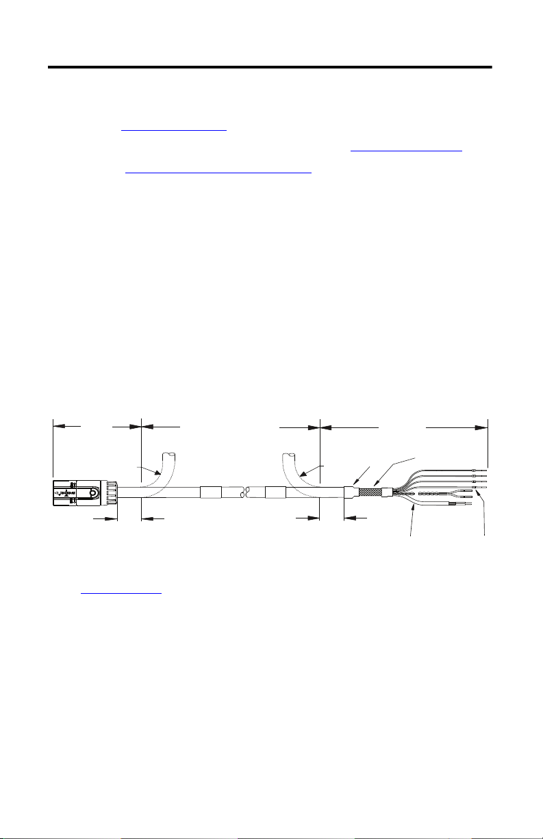
Continuous-flex Zone
Installation
Area
Installation
Area
Signal
Labels
Exposed Shield
Shrink
Wrap
Refer to Specifications
on page 3 for recommended
continuous-flex zone radius values.
Insulated and
Shielded
Twi ste d Pai r
2090-CSBM1DF-10AFxx cable shown.
76.2 mm
(3.0 in.)
76.2 mm
(3.0 in.)
Bend
Radius
Bend Radius
Follow these guidelines when installing a single motor cable:
• Do not bend the cable within 76.2 mm (3.0 in.) of the connector or the flying-lead end.
See the Installation Guidelines
illustration.
• Do not exceed the bend radius limitation specified in the Specifications on page 3.
• Refer to Cable Pinouts and Schematics on page 3 to identify each wire and its respective
drive connection.
• Remove and discard the protective sleeve from the data signal wires shortly before you
install these wires on the feedback connector kit.
• Connect unused brake conductors to the drive to prevent accidental contact.
For continuous-flex cables, follow these additional installation requirements:
• The continuous-flex zone is the area where the cable can repeatedly flex up to its
specified bend radius.
• Installation areas require rigid mounting to prevent the cable from flexing where it
connects to other components.
Installation Guidelines
Rockwell Automation Publication 2090-IN049A-EN-P - October 2013
Page 3

Single Motor Cables with Circular DIN Connector Type 740 3
U
V
W
GND
BRK+
BRK-
+
U
V
W
1
2
L
H
U
V
2
+
H
L
1
N
W
The braided shields
are grounded to the
motor connector.
Shield Connection
To
Drive
Twi ste d Wi re Pa ir
Braided Shield
To
Motor
Brown
Black
Blue
Green/Yellow
Black
White
Blue
White/Blue
Braided Shield
Cable Pinouts and Schematics
This diagrams provides wire colors and pinouts for single motor cables with brake conductors.
2090-CSBM1DF
-10AFxx Cable (with brake)
Specifications
Additional specifications for each cable are available in the Kinetix Motion Accessories
.
Specifications Technical Data, publication GMC-TD004
Attribute 2090-CSBM1DF-10AFxx
Conducto r size (gauge):
DC bus
Digital servo link (data)
(1)
Brake
Diameter 19 mm (0.75 in.)
Continuous-flex zone radius, max 190 mm (7.5 in.)
(1) Controlled impedance data pair.
5.4 mm2 (10 AWG)
0.4 mm
0.4 mm
2
(22 AWG)
2
(22 AWG)
Rockwell Automation Publication 2090-IN049A-EN-P - October 2013
Page 4

Additional Resources
These documents contain information concerning related products from Rockwell Automation.
Resource Description
Kinetix 5500 Servo Drives User Manual, publication
2198-UM001
Kinetix 5500 Feedback Connector Kit Installation
Instructions, publication 2198-IN002
Kinetix VP Low-inertia Servo Motor with 063…165 mm
Frame Size Installation Instructions, publication VPL-IN001
Information on installing, configuring, starting, and
troubleshooting a Kinetix® 5500 servo drive system with a servo
motor.
Information on installing the Kinetix 5500 feedback connector kit.
Information on the installation of your Kinetix VP servo motor with
063…165 mm frame size.
You can view or download publications at http://www.rockwellautomation.com/literature
To order paper copies of technical documentation, contact your Allen-Bradley distributor or
Rockwell Automation sales representative.
Allen-Bradley, Kinetix, Rockwell Software, and Rockwell Automation are trademarks of Rockwell Automation, Inc.
Trademarks not belonging to Ro ckwell Automation are property of their respective companies.
.
Rockwell Otomasyon Ticaret A.Ş., Kar Plaza İş Merkezi E Blok Kat:6 34752 İçerenköy, İstanbul, Tel: +90 (216) 5698400
Publication 2090-IN049A-EN-P - October 2013 PN-226153
Copyright © 2013 Rockwell Automation, Inc. All rights reserved. Printed in the U.S.A.
 Loading...