

Page 1
Installation Instructions
SpeedTec Right-angle Standard Power and
Feedback Cables
Catalog Numbers 2090-CFBM7DF-CERAxx, 2090-CPBM7DF-16RAxx
Topi c Page
Important User Information 2
Before You Begin 3
Cable Installation Guidelines 4
Connector Rotation or Repositioning 5
2090-CFBM7DF-CERAxx Cable Outline and S chematic 6
2090-CPBM7DF-16RAxx Cable Outline and Schematic 6
Cable Specifications 7
Additional Resources 8
About Right-angle Standard Feedback and Power Cables
Standard feedback and power cables have an M23 SpeedTec DIN connector at the motor end,
and flying leads at the drive end. These cables can be bent or reformed during installation or
maintenance, but should not be used in a continuous flex operation.
Connectors on these cables can be rotated or repositioned to the left or right.
• The feedback connector rotates up to 200° to the right of center, or 124° to the left of
center.
• The power connector can be repositioned in 90° increments.
Page 2
2 SpeedTec Right-angle Standard Power and Feedback Cables
Important User Information
Solid state equipment has operational characteristics differing from those of electromechanical equipment. Safety Guidelines for
the Application, Installation and Maintenance of Solid State Controls, publication SGI-1.1
Automation sales office or online at http://www.rockwellautomation.com/literature
between solid state equipment and hard-wired electromechanical devices. Because of this difference, and also because of the
wide variety of uses for solid state equipment, all persons responsible for applying this equipment must satisfy themselves that
each intended application of this equipment is acceptable.
In no event will Rockwell Automation, Inc. be responsible or li able for indirect or consequential damages resulting from the use or
application of this equipment.
The examples and diagrams in this manual are included solely for illustrative purposes. Because of the many variables and
requirements associated with any particular installation, Rockwell Automation, Inc. cannot assume responsibilit y or liability for
actual use based on the examples and diagrams.
No patent liability is assumed by Rockwell Automation, Inc. with respect to use of information, circuits, equipment, or software
described in this manual.
Reproduction of the contents of this manual, in whole or in part, without written permission of Rockwell Automation, Inc., is
prohibited.
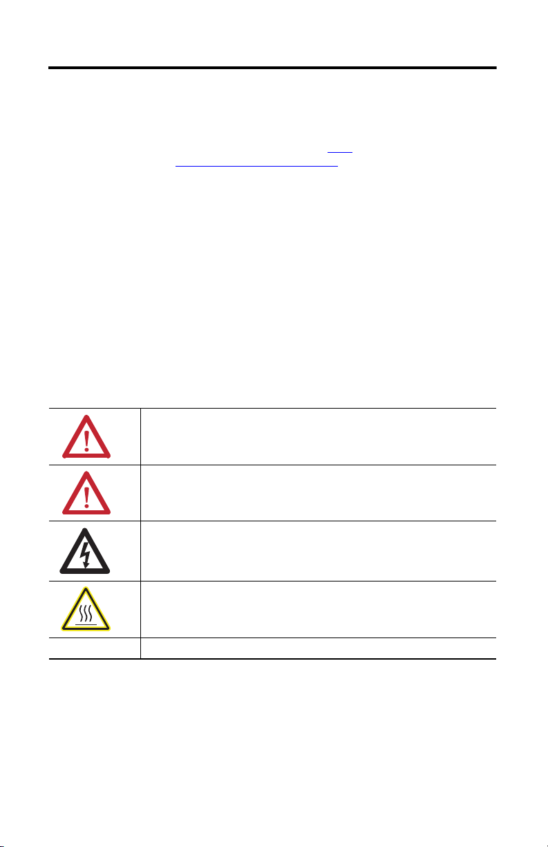
Throughout this manual, when necessary, we use notes to make you aware of safety considerations.
WARNIN G: Identifies information about practices or circumstances that can cause an explosion in a
hazardous environment, which may lead to personal injury or death, property damage, or economic
loss.
, is available from your local Rockwell
) describes some important differences
ATTENTION: Identifies information about practices or circumstances that can lead to personal injury or
death, property damage, or economic loss. Attentions help you identify a hazard, avoid a hazard and
recognize the consequences.
SHOCK HAZARD: Labels may be on or inside the equipment, for example, drive or motor, to alert
people that dangerous voltage may be present.
BURN HAZARD: Labels may be on or inside the equipment, for example, drive or motor, to alert
people that surfaces may reach dangerous temperatures.
IMPORTANT Identifies information that is critical for successful application and understanding of the product.
Publication 2090-IN045A-EN-P - August 2012
Page 3
SpeedTec Right-angle Standard Power and Feedback Cables 3
IMPORTANT
Before You Begin
Remove all packing material from within and around the item. After unpacking, verify the
catalog number against the purchase order., and visually inspect the cable and each connector for
damage. If necessary, notify the carrier of any shipping damage immediately.
Cables are stored and shipped in a coil, and will retain this shape unless you allow the cable to
straighten itself. To straighten a cable, hang a short cable from its mid-point or lay a long cable on
the floor in a straight line. Any coiling that persists in the cable should relax within the next
24 hours. Doing this results in a cable that is easier to install.
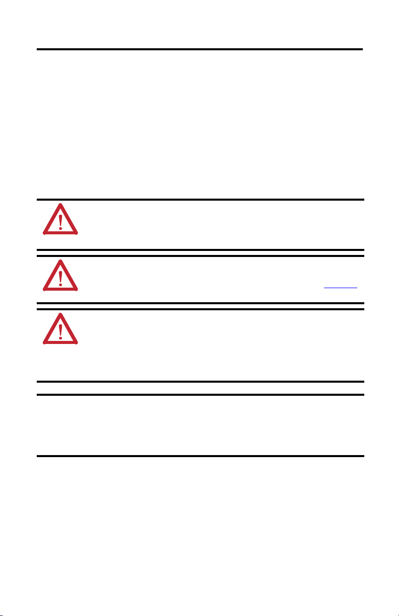
Observe the following precautions when installing the cables in a servo system. Failure to observe
these safety notices could result in personal injury or damage to the motor and equipment.
ATTENTION: Arcing or unexpected motion can occur if the feedback, power, or brake cables are
connected or disconnected while power is applied to the drive.
Always remove power to the servo drive before connecting or disconnecting cables at the drive
or at the motor.
ATTENTION: The maximum length of cabling between the drive and the motor must not
exceed 90 m (295.5 ft), and a maximum of two extension cables may be connected between a
drive and a motor. Refer to Kinetix® Motion Control Selection Guide, publication GMC-SG001
for additional information.
ATTENTION: The examples in this publication show all the available connections, some of
which may not be appropriate for your specific installation. Refer to your drive installation or
user manual for recommended wire trim lengths, and wiring examples appropriate to your
drive and motor application.
Do not connect unused wires. Unused wires may be trimmed and finished as necessary to
prevent accidental contact with other wires or wire shields, or with a ground connection.
,
Motors equipped with SpeedTec-ready DIN connectors are fully compatible with threaded (M4)
cable plugs. SpeedTec-ready DIN motor connectors are also compatible with SpeedTec (M7/E7)
cable plugs when the O-ring on the motor connector is removed.
Motors equipped with threaded DIN (M4) connectors are compatible only with threaded (M4)
cable plugs.
Publication 2090-IN045A-EN-P - August 2012
Page 4

4 SpeedTec Right-angle Standard Power and Feedback Cables
TIP
Bend Zone
Flex Restrictions Apply
2090-CFBM7DF-CERAxx shown
Installation Area
300 mm (12 in.) approx.
Bend Radius
Refer to Cable Specifications
for value.
Installation Area
300 mm (12 in.) approx.
Cable Installation Guidelines
Follow these guidelines when installing a cable.
1. Identify the recommended installation areas and the correct offset from features before
beginning any cable bend.
Features include these areas on the cable:
• Connectors
• Transitions from exposed wire to insulation (for example, flying leads)
• Exposed cable ground shields
The offset from these features should be greater than or equal to (≥1x) the cable
diameter.
2. Keep cable bends within the bend radius specified on page
3. Observe these restrictions when installing the cable:
• The bend zone is the area in which the cable can be bent to its specified bend radius.
• The installation areas require strain relief to minimize cable flexing, and to reduce
the possibility of cable fatigue where the cable connects to other components.
7.
I
You may identify each connection on a cable by attaching a label around the outer insulation of
the wire adjacent to the connection.
4. Observe these restrictions when attaching a cable connector to the motor connector:
a. Align all flat surfaces on the cable connector with the flat surface on the motor
connector.
b. Push the cable connector onto the motor connector to fully seat the connection.
c. Twist the knurled front-end of the cable connector approximately 60° to the right to
secure the connection.
Publication 2090-IN045A-EN-P - August 2012
Page 5

SpeedTec Right-angle Standard Power and Feedback Cables 5
TIP
Connector Rotation or Repositioning
The feedback cable can be rotated 124° to the left of center or 200° to the right of center.
The power cable can be repositioned in 90° increments.
Feedback Cable Rotation
To rotate the feedback cable connector into its final position, follow these steps.
1. Mount the cable on the motor connector.
2. Use two hands while you rotate the connector into position:
a. Grasp both the front and rear sections of the cable shell when rotating the feedback
connector.
b. Use one hand to stabilize the front section of the right-angle connector (the area with
the knurled locking sleeve) and the connector on the motor.
c. Use your other hand to rotate the back section of the feedback connector (the area
with the cable) into position.
See 2090-CFBM7DF-CERAxx Cable Outline and Schematic on page 6 to locate the rotation
point of the feedback connector.
Power Cable Repositioning
To reposition the power cable connector to its final position, follow these steps.
1. Remove the four 2 mm hex screws on the back of the cable connector.
2. Reposition the connector body to the new position (90°, 180°, 270°).
3. Secure the two parts together with the four 2 mm hex screws.
Maximum torque for these screws is 0.25 N•m (2.2 lb•in.).
Publication 2090-IN045A-EN-P - August 2012
Page 6

6 SpeedTec Right-angle Standard Power and Feedback Cables
9
10
11
12
13
14
15
16
17
2
3
4
567
8
1
1
2
3
4
5
6
9
10
11
13
14
12
Length in mm (in.)
Installation Area
300 (12) ± 25 (1)
Installation Area
300 (12) ± 25 (1)
81 (3.2)
61
(2.4)
Rotation Point
Connector dimensions
are for ref erence only.
Wire Connection
Twi ste d Wir e Pa ir
Black
White/Black
Red
White/Red
Green
White/Green
Gray
White/Gray
Orange
White/Orange
DRAIN
SIN+/AM+
SIN-/AM-
COS+/B M+
COS-/B M-
DATA+/IM+/R1
DATA-/IM-/R2
EPWR 9V DC
COM
EPWR 5V DC
TS+
TS-
COM
Wire Co nnecti on
Twisted Wire Pair
Length in mm (in.)
Installation Area
300 (12) ± 25 (1)
Installation Area
300 (12) ± 25 (1)
71 (2.8)
Hex Screw (4x)
82
(3.2)
Brown
Black
Blue
Green/Yellow
White
Black
Shield
Brown
Black
Blue
Grn/Ylw
Black
White
2090-CFBM7DF-CERAxx Cable Outline and Schematic
2090-CPBM7DF-16RAxx Cable Outline and Schematic
BC
G
D
E
A
F
L
H
Publication 2090-IN045A-EN-P - August 2012
A
B
C
F
G
E
H
L
U
V
W
MBRK+
MBRK-
Page 7

SpeedTec Right-angle Standard Power and Feedback Cables 7
Cable Specifications
Specifications for similar cables are available in the Kinetix Motion Accessories Technical Data,
publication GMC-TD004.
Attribute Feedback Cable Power Cable
Catalog number 2090-CFBM7DF-CERAxx 2 090-CPBM7DF-16RAxx
Wire size 22 AWG (data) 16 AWG (power)
(1)
Cable diameter
Bend radius of cable 98 mm (3.90 in.) 116 mm (4.6 in.)
Length 3, 6, 9, 15 m (10, 16, 30, 49 ft)
Connector IP rating IP67 (dust tight, water immersion) IP54 (dust protected, splashing water)
O-ring expansion period One minute between disconnection and reconnection
(1) Cable diameter tolerance is ± 0.04mm (0.005 in.).
9.8 mm (0.39 in.) 11.6 mm (0.46 in.)
18 AWG (brake)
Publication 2090-IN045A-EN-P - August 2012
Page 8

Additional Resources
These documents contain information concerning related products from Rockwell Automation.
Resource Description
Kinetix 300 EtherNet/IP Indexing Servo Drive User
Manual, publication 2097-UM001
Kinetix 2000 Multi-axis Servo Drive User Manual,
publication 2093-UM001
Kinetix 6000 Multi-axis Servo Drives User Manual,
publication 2094-UM001
Kinetix 6200 and Kinetix 6500 Modular Multi-axis
Servo Drives User Manual, publication 2094-UM002
Kinetix 7000 High Power Servo Drive User Manual,
publication 2099-UM001
Ultra3000 Digital Servo Drives Installation Manual,
publication 2098-IN003
Ultra3000 Digital Servo Drives Integration Manual,
publication 2098-IN005
Allen-Bradley Industrial Automation Glossary,
publication AG-7.1
System Design for Control of Electrical Noise Reference
Manual, publication GMC-RM001
Kinetix Rotary Motion Specifications Technical Data,
publication GMC-TD001
or
Information on installing, configuring, starting, and troubleshooting
Kinetix motion control drive systems containing these
products.
A glossary of industrial automation terms and abbreviations.
Information, examples, and techniques designed to minimize system
failures caused by electrical noise.
Catalog numbers and product specifications, including performance,
environmental, certifications, load force, and dimension drawings for
Allen-Bradle
y® rotary products.
You can view or download publications at http://rockwellautomation.com/literature
. To order
paper copies of technical documentation, contact your local Allen-Bradley distributor or
Rockwell Automation sales representative.
Allen-Bradley, Kinetix , Rockwell Software , Rockwell Automation, Ultra3000, and Ultra5 000 are trademarks of Rockwell Automati on, Inc.
Trademarks not belonging to Rockwell Automation are property of their respective companies.
Publication 2090-IN045A-EN-P August 2012 PN-163667
Copyright © 2012 Rockwell Automation, Inc. All rights reserved. Printed in the U.S.A.
 Loading...