

Page 1
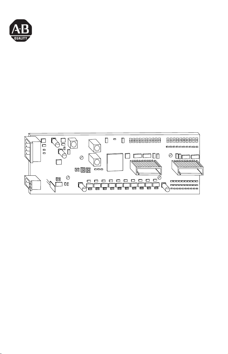
Installation Instructions
10 Input/10 Output
Discrete Embedded I/O Boards
(Cat. No. 1799-D10U10V, -D10U10VL, -D10U10B & -D10U10BL)
42495
The 1799 I/O board (Cat. No. 1799-D
-D10U10BL
network.
This board has 10 inputs and 10 outputs. Inputs are 24V dc sourcing (PNP)
or sinking (NPN). Outputs are self-protected 24V dc sourcing
(1799-D10U10B, -D10U10BL) or sinking (1799-D10U10V, -D10U10VL).
) is a 20-point I/O board which communicates via a DeviceNet™
10U10V, -D10U10VL, -D10U10B &
Publication 1799-IN003B-EN-P - December 2000
Page 2
2 10 Input/10 Output Discrete Embedded I/O Boards
European Communities (EC) Directive Compliance
If this product has the CE mark it is approved for installation within the
European Union and EEA regions. It has been designed and tested to meet
the following directives.
EMC Directive
This product is tested to meet the Council Directive 89/336/EC
Electromagnetic Compatibility (EMC) by applying the following standards,
in whole or in part, documented in a technical construction file:
• EN 50081-2 EMC — Generic Emission Standard, Part 2 — Industrial
Environment
• EN 50082-2 EMC — Generic Immunity Standard, Part 2 — Industrial
Environment
This product is intended for use in an industrial environment.
Low Voltage Directive
This product is tested to meet Council Directive 73/23/EEC Low Voltage, by
applying the safety requirements of EN 61131-2 Programmable Controllers,
Part 2 - Equipment Requirements and Tests. For specific information
required by EN 61131-2, see the appropriate sections in this publication, as
well as the Allen-Bradley publication Industrial Automation Wiring and
Grounding Guidelines For Noise Immunity, publication 1770-4.1.
This equipment is classified as open equipment and must be mounted in
an enclosure during operation to provide safety protection.
ATTENTION
Before handling this board, be certain you are
grounded to prevent any electrostatic
discharge.
!
Publication 1799-IN003B-EN-P - December 2000
Page 3
10 Input/10 Output Discrete Embedded I/O Boards 3
Package Contents
Your package contains:
• one 1799 I/O Board
• installation instructions
Optional Hardware
All mating connectors and mounting hardware must be ordered separately.
The table below identifies the different connector and hardware options.
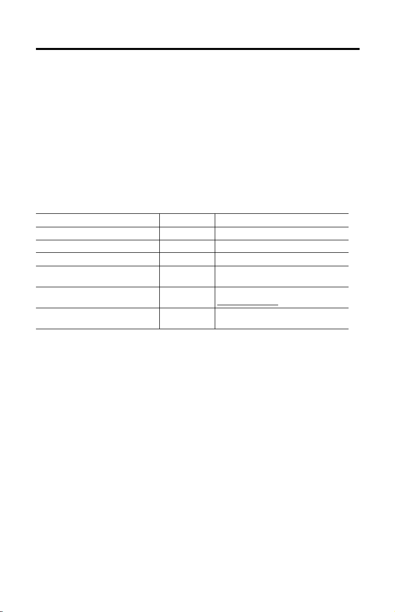
Option Catalog Number Third Party Supplier & Part Number
2 DIN rail brackets (4 screws) 1799-BRKD N/A
clear plastic cover (4 stand-offs, 4 screws) 1799-COV20 N/A
mounting plate (4 screws) 1799-MP20 N/A
2, 12-position, gold-plated I/O mating
connectors
5-position, open-style plug for DeviceNet 1799-DNETCON DeviceNet Buyer’s Guide at
2-position plug for auxiliary power 1799-AUXCON Weidmuller - 171385
1799-12SPCON Phoenix - FK-MC 0.5/12-ST-2.5AU - 192432
http://www.odva.org
PCD - ELFP02211
Install Your Board
To install the board you must:
• Set the node address
• Mount the board (brackets, mounting plate)
• Connect the board (DeviceNet, auxiliary power, I/O)
• Mount the optional plastic cover
• Communicate with your board
• Configure the parameters
More detailed information about each of these steps is in the following
procedures.
Publication 1799-IN003B-EN-P - December 2000
Page 4
4 10 Input/10 Output Discrete Embedded I/O Boards
Set the Node Address
Valid node addresses are 00 to 63.
Set the node address using the rotary switches or a DeviceNet software
TM
configuration tool like RSNetWorx for DeviceNet
between 64 and 99 allows the software to have address control.
Each board is shipped with the node address set to 63 in the board’s
memory. The rotary switches are set for position 99 at shipment. The
switches are located near the center of the board. The two switches are:
• MSD (most significant digit)
• LSD (least significant digit)
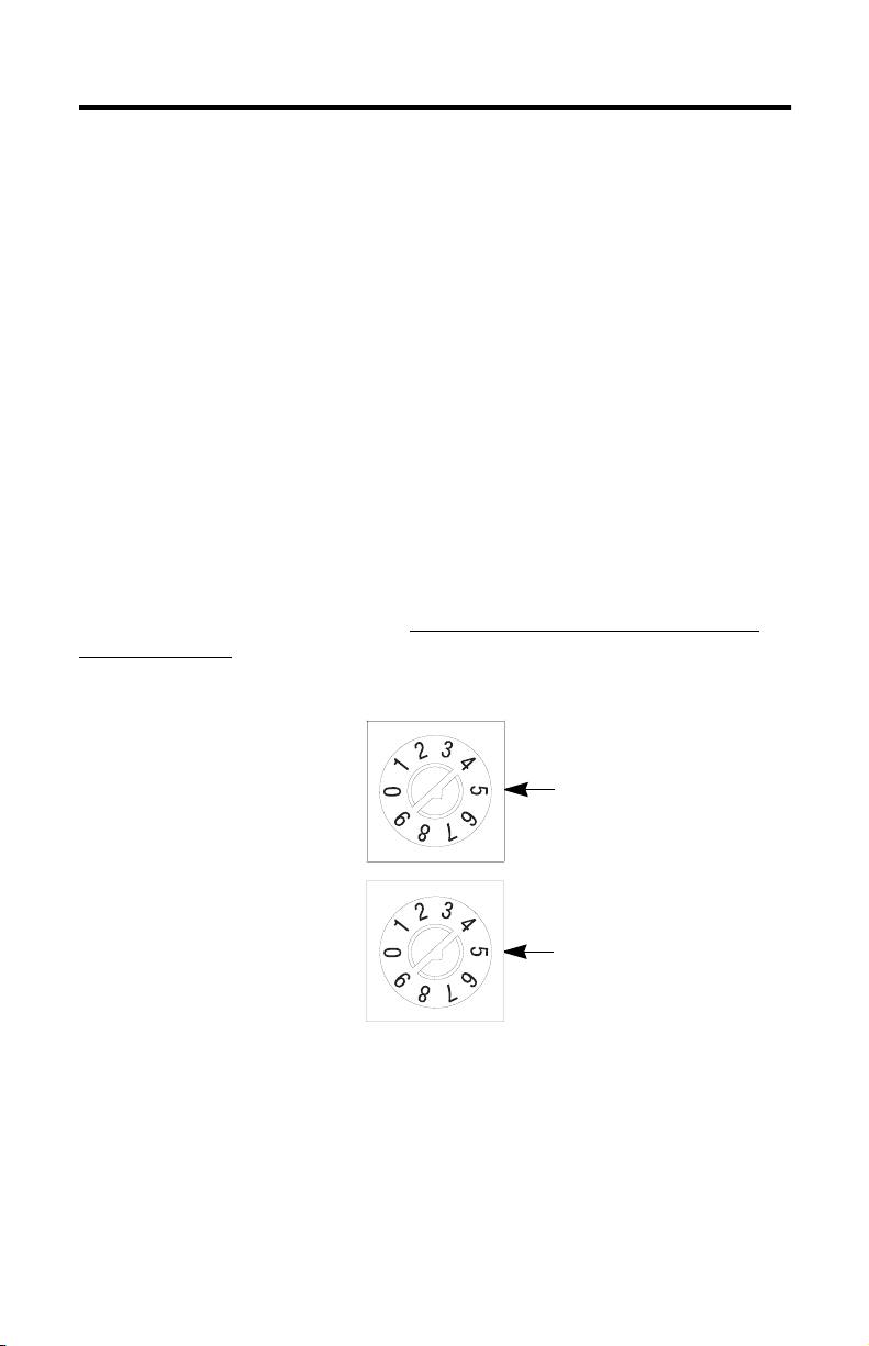
To reset the node address, use a small blade screwdriver to rotate the
switches. Line up the small arrow on the switch with the number setting
you wish to use.
The rotary switches are read at board power up only. Settings between 64
and 99 cause the board to use the last valid node address stored in the
board’s memory. Example: The last setting was 40. If a change is made to
68, and then you power up, the address will default to 40.
. Setting the switches
LSD (S2)
MSD (S1)
Switches are
shown in the 99
position.
42496
The board is equipped with AutoBaud detect. AutoBaud lets the board
detect the baud rate on your DeviceNet network and automatically adjusts
to that rate. The board is shipped with AutoBaud enabled.
Publication 1799-IN003B-EN-P - December 2000
Page 5
10 Input/10 Output Discrete Embedded I/O Boards 5
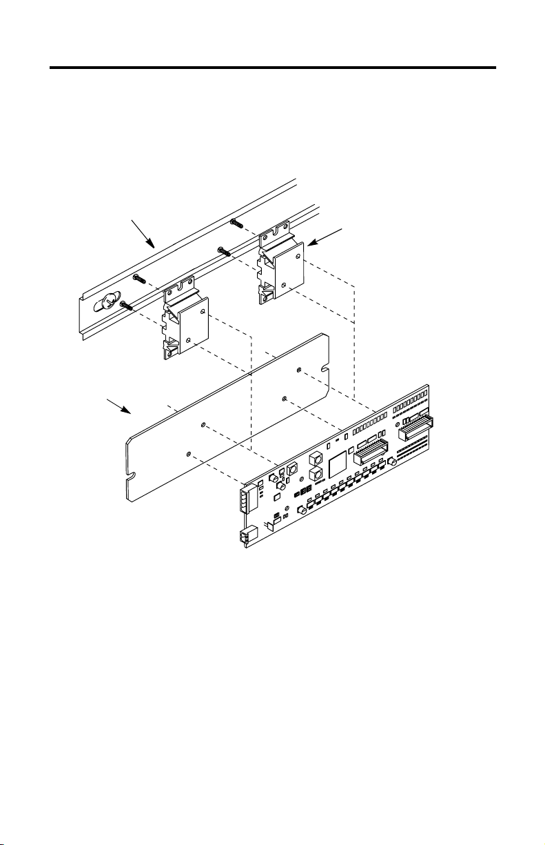
Mount the Board
Use the following picture to help you mount the board to a DIN rail using
DIN rail brackets (1799-BRKD) or to a mounting plate (1799-MP20).
DIN rail
or
mounting plate
DIN rail bracket
or
42507
The board can also be mounted in an enclosure with pre-tapped holes,
which accommodate M3 x 0.5mm screws.
Publication 1799-IN003B-EN-P - December 2000
Page 6

6 10 Input/10 Output Discrete Embedded I/O Boards
Board Dimensions
3.90in.
99.00mm
3.00in.
76.20mm
0.45in.
11.43mm
2.0in.
50.80mm
1.08in.
27.30mm
6.40in.
162.56mm
Mounting Plate Dimensions (front view)
7.00in.
177.8mm
2.10in.
53.34mm
0.75in.
19.05mm
0.13in.
3.30mm
0.75in.
19.05mm
0.63in.
15.88mm
1.05in.
26.67mm
42562
42506
Publication 1799-IN003B-EN-P - December 2000
Page 7

10 Input/10 Output Discrete Embedded I/O Boards 7
Connect the Board
Use the following picture and tables to help you connect the DeviceNet,
auxiliary power, and I/O connectors to the board.
Pin 5
(bottom)
Pin 12 (right)
I/O Connector (P4)
42508
I/O Connector (P3)
DeviceNet Connector (P2)
Pin 1 (left)
Pin 1
(top)
Pin 2 (bottom)
Auxiliary Power Connector (P1)
The following tables identify the pins of each connector.
P1 Auxiliary Power Connector P3 I/O Connector P4 I/O Connector
Pin Signal Pin Signal Pin Signal
1 24V dc 1 Output 0 1 Input 0
2 24V dc Ret 2 Output 1 2 Input 1
3 Output 2 3 Input 2
4 24V dc Ret 4 In Common
5 Output 3 5 Input 3
P2 DeviceNet Connector
Pin Insulation Colors 7 Output 5 7 Input 5
1 Black 8 Output 6 8 Input 6
2 Blue 9 24V dc 9 In Common
3 Shield 10 Output 7 10 Input 7
4 White 11 Output 8 11 Input 8
5 Red 12 Output 9 12 Input 9
6 Output 4 6 Input 4
ATTENTION
!
• For maximum noise immunity, input cable return wires must be
properly terminated.
• When inputs are connected in loopback, return wires should be
connected together.
• I/O cable length should be less than 30 meters (98.43 feet).
Publication 1799-IN003B-EN-P - December 2000
Page 8

8 10 Input/10 Output Discrete Embedded I/O Boards
Auxiliary Power Specifications
The power source used to supply the auxiliary power to the outputs must
be one of the following:
• a 10-30V dc Class 2 Power Supply
or
• a 10-30V dc UL Listed or Recognized Power Supply with isolated
outputs limited to 200 volt-amperes in each ungrounded output line.
This condition requires that the board and power source be
mounted in a suitable ultimate enclosure with proper spacings
maintained.
Connect the Field Output Device to the Output Connector (P3)
The 1799-D10U10B and -D10U10BL boards have outputs which supply
current to your field output device (sourcing outputs). Use the wiring
diagram below to connect the outputs on these boards.
1799-D10U10B & - D10U10BL Outputs (Sourcing)
3
0
24V dc
1
2
Return
4
The 1799-D10U10V and -D10U10VL boards have outputs which receive
current from your field output device (sinking outputs). Use the wiring
diagram below to configure the outputs on these boards.
Publication 1799-IN003B-EN-P - December 2000
6
24V dc
5
7
+
_
Load
9
8
42491
Page 9

10 Input/10 Output Discrete Embedded I/O Boards 9
1799-D10U10V & D10U10VL Outputs (Sinking)
c
d
0 2 24V dc
Return
3456
Load
78 91
V
4
2
+
_
42492
Connect the Field Input Device to the Input Connector (P4)
The 1799-D10U10B, -D10U10BL, -D10U10V, and -D10U10VL boards have
universal inputs which allow operation with either sourcing or sinking
input devices. The universal feature lets you configure the inputs as either
sinking or sourcing. Use the following wiring diagrams to connect the
inputs on the boards.
IMPORTANT
All field input devices must be of the same type,
either sinking or sourcing. The board will not
operate if the types are mixed.
Publication 1799-IN003B-EN-P - December 2000
Page 10

10 10 Input/10 Output Discrete Embedded I/O Boards
Inputs (Sourcing)
Inputs (Sinking)
023456In
+
_
0234567891
+
_
Common
In
Common
In
Common
In
Common
7891
42493
42494
Mount the Optional Plastic Cover
After all wires are connected to the board, the optional plastic cover can be
mounted onto the board.
1. Place the four stand-offs onto the mounting screws and tighten.
2. Align the holes on the cover with the stand-offs.
3. Place the screws into the stand-offs and tighten.
Publication 1799-IN003B-EN-P - December 2000
Page 11

10 Input/10 Output Discrete Embedded I/O Boards 11
Use the following picture to help you mount the cover.
Mounting Screws
Stand-Offs
2.35in.
59.69mm
Communicate with Your Board
This board’s I/O is exchanged with the master on DeviceNet
through a cyclic, polled or change-of-state connection.
1.08in.
27.31mm
42505
The board consumes and produces I/O data as follows:
I/O Connection Type Consumes Produces
Cyclic 2 Bytes 2 Bytes
Polled 2 Bytes 2 Bytes
Change-of-State 2 Bytes 2 Bytes
Cyclic - the board will produce and consume its I/O cyclically at the rate
configured by the master on DeviceNet.
Publication 1799-IN003B-EN-P - December 2000
Page 12

12 10 Input/10 Output Discrete Embedded I/O Boards
Polled - the master initiates communication by sending its polled I/O
message to the board. The board consumes the message, updates any
outputs and produces a response containing the input data.
Change-of-State - a production occurs when an input changes. A
heartbeat production occurs if no input condition change occurs within the
expected packet rate. This heartbeat production tells the master that the
board is alive and ready to communicate. Consumption occurs when data
changes and the master produces new output data to the board.
Refer to the table below for the word/bit definitions:
Byte Bit 7 Bit 6 Bit 5 Bit 4 Bit 3 Bit 2 Bit 1 Bit 0
Produced 0 Input 7 Input 6 Input 5 Input 4 Input 3 Input 2 Input 1 Input 0
Produced 1 Reserved Input 9 Input 8
Consumed 0 Output 7 Output 6 Output 5 Output 4 Output 3 Output 2 Output 1 Output 0
Consumed 1 Reserved Output 9 Output 8
Configure the Parameters
The 1799 I/O boards have eight parameters that are configurable through a
DeviceNet software configuration tool like RSNetWorx for DeviceNet. The
DeviceNet configuration tools require an Electronic Data Sheet (EDS) for
the 1799 I/O boards in order to configure the module’s parameters. The
EDS file can be found at the ODVA Web site (http://www.odva.org).
Use the descriptions in the table below to help you configure the
parameters.
Parameter Description
Baud Rate Controls the board’s data rate.
Auto-Baud Enables the board to match the network’s data rate. When enabled,
Input Off-to-On
Filter Time
Input On-to-Off
Filter Time
Output Idle State Controls the state of each output when the DeviceNet master is in
Publication 1799-IN003B-EN-P - December 2000
Baud Rate parameter is ignored.
Controls the amount of time the input must be in the ‘on’ state
before the board reports the input as ‘on.’
Controls the amount of time the input must be in the ‘off’ state
before the board reports the input as ‘off.’
an idle state.
Page 13

10 Input/10 Output Discrete Embedded I/O Boards 13
Parameter Description
Output Fault State Controls the state of each output when the board loses
communication with the DeviceNet master.
Output Idle Value Controls the value that outputs take on when the output idle state is
set to ‘use idle value.’
Output Fault Value Controls the value that outputs take on when the output fault state
is set to ‘use fault value.’
The DeviceLogix™ capable boards, 1799-D10U10BL and -D10U10VL, have
additional parameters which are described in the DeviceLogix
configuration tool documentation.
Troubleshoot with the Indicators
This board has the following indicators, shown in the picture below:
• Board status indicator
• Network status indicator
• DeviceLogix status
• Auxiliary power indicator
• I/O status indicators
I/0 Status
Indicators
Auxiliary Power
Indicator
DeviceLogix
Status Indicator
Board Status
Network Status
Indicator
Indicator
Publication 1799-IN003B-EN-P - December 2000
42509
Page 14

14 10 Input/10 Output Discrete Embedded I/O Boards
Board Status Indicator (labeled MOD)
Indication Status
None No Power
Green
Blinking
Solid
Red
Blinking
Solid
Needs commissioning
Device operational
Minor fault
Critical fault
Network Status Indicator (labeled NET)
Indication Status
None Not On-line
Green
Red
Blinking
Solid
Blinking
Solid
On-line/No connections
On-line/Connected
Connection timed out
Failed communication: A duplicate
node address exists or module is at
the wrong baud rate.
DeviceLogix Status Indicator (labeled DS2)
Indication Status
None Logic disabled
Green
Solid
Blinking
Logic enabled
Local forces applied and local logic enabled
Auxiliary Power Indicator (labeled AUX PWR)
Indication Status
None No auxiliary power
Green Auxiliary power present
I/O Status Indicators (labeled Inputs and Outputs)
Indication Status
None Input or output point off
Yellow Input or output point on
Publication 1799-IN003B-EN-P - December 2000
Page 15

10 Input/10 Output Discrete Embedded I/O Boards 15
Technical Support
For additional troubleshooting information on the 1799 Embedded I/O
Boards, access Rockwell Automation’s technical support services at
440.646.5800 or on the Web at http://www.ab.com
.
Specifications
10 Input/10 Output Board - Cat. No. 1799-D10U10B, -D10U10BL, -D10U10V & -D10U10VL
Input Specification Max Min
Inputs per block 10 Sinking or Sourcing, Type 1 + compatible
Off-State
Voltage
Current
On-State
Voltage
Current
Output Specification
Outputs per block 10 Sinking or Sourcing, 0.5A, Short Circuit Protected,
Output Auxiliary Voltage 30V 10V
On-State Voltage Drop 250 mV -
On-State Current 0.5A Off-State Leakage 20 µΑ -
Board Current (all outputs on) 4.0A -
Surge Current - for 10ms, repeatable
every 2s (individual outputs)
General Specifications
DeviceNet Power
Voltage
Current
DeviceNet Power
Circuit Type Class 2
Auxiliary Power
Voltage
Current
LED Indicators Board Status - red/green
5V dc
1.5 mA
30V dc
6 mA
Pilot Duty
1.0A
25V dc
125 mA
30V dc
4.0A (all outputs on)
Network Status - red/green
Auxiliary Power - green
Logic Status - green
Input Point LED - yellow
Output Point LED -yellow
-
-
10V dc
2 mA
11V dc
-
10V dc
100 mA (all outputs off)
Publication 1799-IN003B-EN-P - December 2000
Page 16

10 Input/10 Output Board - Cat. No. 1799-D10U10B, -D10U10BL, -D10U10V & -D10U10VL
General Specifications cont.
Wire Gauge
I/O
Auxiliary
Dimensions
inches (millimeters)
Environmental Conditions
Operational Temperature
Storage Temperature
Relative Humidity
Shock Operating
Non-Operating
Vibration
Agency Certifications
(When product or packaging is
marked)
20 AWG
12 AWG
1.0H x2.0W x 6.4D
(26H x51W x 163D)
-10 to 80
-40 to 85
5 to 95% non-condensing
30g
50g
5g @ 10-50 H
28 AWG
28 AWG
o
C (14 to 176o F)
o
C (-40 to 185o F)
z
marked for all applicable directives
marked for all applicable acts
conformance tested
DeviceNet is a trademark of Open DeviceNet Vendor Association (ODVA).
Allen-Bradley is a trademark of Rockwell Automation
RSNetWorx for DeviceNet is a trademark of Rockwell Software.
DeviceLogix is a trademark of Rockwell Automation Allen-Bradley, Inc.
Publication 1799-IN003B-EN-P - December 2000 PN 957464-49
Supersedes Publication 1799-IN003A-EN-P - October 2000 © 2000 Rockwell Interna tional Corporation. Printed in the U.S.A.
 Loading...